WO2020213249A1 - 延伸装置および延伸装置の部品交換方法 - Google Patents
延伸装置および延伸装置の部品交換方法 Download PDFInfo
- Publication number
- WO2020213249A1 WO2020213249A1 PCT/JP2020/006375 JP2020006375W WO2020213249A1 WO 2020213249 A1 WO2020213249 A1 WO 2020213249A1 JP 2020006375 W JP2020006375 W JP 2020006375W WO 2020213249 A1 WO2020213249 A1 WO 2020213249A1
- Authority
- WO
- WIPO (PCT)
- Prior art keywords
- link
- links
- pair
- sprocket
- membrane
- Prior art date
- Legal status (The legal status is an assumption and is not a legal conclusion. Google has not performed a legal analysis and makes no representation as to the accuracy of the status listed.)
- Ceased
Links
Images



Classifications
-
- B—PERFORMING OPERATIONS; TRANSPORTING
- B29—WORKING OF PLASTICS; WORKING OF SUBSTANCES IN A PLASTIC STATE IN GENERAL
- B29C—SHAPING OR JOINING OF PLASTICS; SHAPING OF MATERIAL IN A PLASTIC STATE, NOT OTHERWISE PROVIDED FOR; AFTER-TREATMENT OF THE SHAPED PRODUCTS, e.g. REPAIRING
- B29C55/00—Shaping by stretching, e.g. drawing through a die; Apparatus therefor
- B29C55/02—Shaping by stretching, e.g. drawing through a die; Apparatus therefor of plates or sheets
- B29C55/10—Shaping by stretching, e.g. drawing through a die; Apparatus therefor of plates or sheets multiaxial
- B29C55/12—Shaping by stretching, e.g. drawing through a die; Apparatus therefor of plates or sheets multiaxial biaxial
- B29C55/16—Shaping by stretching, e.g. drawing through a die; Apparatus therefor of plates or sheets multiaxial biaxial simultaneously
- B29C55/165—Apparatus therefor
-
- B—PERFORMING OPERATIONS; TRANSPORTING
- B29—WORKING OF PLASTICS; WORKING OF SUBSTANCES IN A PLASTIC STATE IN GENERAL
- B29C—SHAPING OR JOINING OF PLASTICS; SHAPING OF MATERIAL IN A PLASTIC STATE, NOT OTHERWISE PROVIDED FOR; AFTER-TREATMENT OF THE SHAPED PRODUCTS, e.g. REPAIRING
- B29C35/00—Heating, cooling or curing, e.g. crosslinking or vulcanising; Apparatus therefor
- B29C35/02—Heating or curing, e.g. crosslinking or vulcanizing during moulding, e.g. in a mould
-
- B—PERFORMING OPERATIONS; TRANSPORTING
- B29—WORKING OF PLASTICS; WORKING OF SUBSTANCES IN A PLASTIC STATE IN GENERAL
- B29C—SHAPING OR JOINING OF PLASTICS; SHAPING OF MATERIAL IN A PLASTIC STATE, NOT OTHERWISE PROVIDED FOR; AFTER-TREATMENT OF THE SHAPED PRODUCTS, e.g. REPAIRING
- B29C48/00—Extrusion moulding, i.e. expressing the moulding material through a die or nozzle which imparts the desired form; Apparatus therefor
- B29C48/001—Combinations of extrusion moulding with other shaping operations
- B29C48/0018—Combinations of extrusion moulding with other shaping operations combined with shaping by orienting, stretching or shrinking, e.g. film blowing
-
- B—PERFORMING OPERATIONS; TRANSPORTING
- B29—WORKING OF PLASTICS; WORKING OF SUBSTANCES IN A PLASTIC STATE IN GENERAL
- B29C—SHAPING OR JOINING OF PLASTICS; SHAPING OF MATERIAL IN A PLASTIC STATE, NOT OTHERWISE PROVIDED FOR; AFTER-TREATMENT OF THE SHAPED PRODUCTS, e.g. REPAIRING
- B29C48/00—Extrusion moulding, i.e. expressing the moulding material through a die or nozzle which imparts the desired form; Apparatus therefor
- B29C48/25—Component parts, details or accessories; Auxiliary operations
- B29C48/30—Extrusion nozzles or dies
-
- B—PERFORMING OPERATIONS; TRANSPORTING
- B29—WORKING OF PLASTICS; WORKING OF SUBSTANCES IN A PLASTIC STATE IN GENERAL
- B29C—SHAPING OR JOINING OF PLASTICS; SHAPING OF MATERIAL IN A PLASTIC STATE, NOT OTHERWISE PROVIDED FOR; AFTER-TREATMENT OF THE SHAPED PRODUCTS, e.g. REPAIRING
- B29C48/00—Extrusion moulding, i.e. expressing the moulding material through a die or nozzle which imparts the desired form; Apparatus therefor
- B29C48/25—Component parts, details or accessories; Auxiliary operations
- B29C48/88—Thermal treatment of the stream of extruded material, e.g. cooling
- B29C48/911—Cooling
-
- B—PERFORMING OPERATIONS; TRANSPORTING
- B29—WORKING OF PLASTICS; WORKING OF SUBSTANCES IN A PLASTIC STATE IN GENERAL
- B29C—SHAPING OR JOINING OF PLASTICS; SHAPING OF MATERIAL IN A PLASTIC STATE, NOT OTHERWISE PROVIDED FOR; AFTER-TREATMENT OF THE SHAPED PRODUCTS, e.g. REPAIRING
- B29C55/00—Shaping by stretching, e.g. drawing through a die; Apparatus therefor
- B29C55/02—Shaping by stretching, e.g. drawing through a die; Apparatus therefor of plates or sheets
- B29C55/10—Shaping by stretching, e.g. drawing through a die; Apparatus therefor of plates or sheets multiaxial
- B29C55/12—Shaping by stretching, e.g. drawing through a die; Apparatus therefor of plates or sheets multiaxial biaxial
-
- B—PERFORMING OPERATIONS; TRANSPORTING
- B29—WORKING OF PLASTICS; WORKING OF SUBSTANCES IN A PLASTIC STATE IN GENERAL
- B29C—SHAPING OR JOINING OF PLASTICS; SHAPING OF MATERIAL IN A PLASTIC STATE, NOT OTHERWISE PROVIDED FOR; AFTER-TREATMENT OF THE SHAPED PRODUCTS, e.g. REPAIRING
- B29C55/00—Shaping by stretching, e.g. drawing through a die; Apparatus therefor
- B29C55/02—Shaping by stretching, e.g. drawing through a die; Apparatus therefor of plates or sheets
- B29C55/20—Edge clamps
-
- B—PERFORMING OPERATIONS; TRANSPORTING
- B29—WORKING OF PLASTICS; WORKING OF SUBSTANCES IN A PLASTIC STATE IN GENERAL
- B29C—SHAPING OR JOINING OF PLASTICS; SHAPING OF MATERIAL IN A PLASTIC STATE, NOT OTHERWISE PROVIDED FOR; AFTER-TREATMENT OF THE SHAPED PRODUCTS, e.g. REPAIRING
- B29C71/00—After-treatment of articles without altering their shape; Apparatus therefor
- B29C71/02—Thermal after-treatment
-
- B—PERFORMING OPERATIONS; TRANSPORTING
- B29—WORKING OF PLASTICS; WORKING OF SUBSTANCES IN A PLASTIC STATE IN GENERAL
- B29C—SHAPING OR JOINING OF PLASTICS; SHAPING OF MATERIAL IN A PLASTIC STATE, NOT OTHERWISE PROVIDED FOR; AFTER-TREATMENT OF THE SHAPED PRODUCTS, e.g. REPAIRING
- B29C48/00—Extrusion moulding, i.e. expressing the moulding material through a die or nozzle which imparts the desired form; Apparatus therefor
- B29C48/03—Extrusion moulding, i.e. expressing the moulding material through a die or nozzle which imparts the desired form; Apparatus therefor characterised by the shape of the extruded material at extrusion
- B29C48/07—Flat, e.g. panels
- B29C48/08—Flat, e.g. panels flexible, e.g. films
-
- B—PERFORMING OPERATIONS; TRANSPORTING
- B29—WORKING OF PLASTICS; WORKING OF SUBSTANCES IN A PLASTIC STATE IN GENERAL
- B29C—SHAPING OR JOINING OF PLASTICS; SHAPING OF MATERIAL IN A PLASTIC STATE, NOT OTHERWISE PROVIDED FOR; AFTER-TREATMENT OF THE SHAPED PRODUCTS, e.g. REPAIRING
- B29C48/00—Extrusion moulding, i.e. expressing the moulding material through a die or nozzle which imparts the desired form; Apparatus therefor
- B29C48/25—Component parts, details or accessories; Auxiliary operations
- B29C48/28—Storing of extruded material, e.g. by winding up or stacking
-
- B—PERFORMING OPERATIONS; TRANSPORTING
- B29—WORKING OF PLASTICS; WORKING OF SUBSTANCES IN A PLASTIC STATE IN GENERAL
- B29C—SHAPING OR JOINING OF PLASTICS; SHAPING OF MATERIAL IN A PLASTIC STATE, NOT OTHERWISE PROVIDED FOR; AFTER-TREATMENT OF THE SHAPED PRODUCTS, e.g. REPAIRING
- B29C48/00—Extrusion moulding, i.e. expressing the moulding material through a die or nozzle which imparts the desired form; Apparatus therefor
- B29C48/25—Component parts, details or accessories; Auxiliary operations
- B29C48/30—Extrusion nozzles or dies
- B29C48/305—Extrusion nozzles or dies having a wide opening, e.g. for forming sheets
-
- B—PERFORMING OPERATIONS; TRANSPORTING
- B29—WORKING OF PLASTICS; WORKING OF SUBSTANCES IN A PLASTIC STATE IN GENERAL
- B29C—SHAPING OR JOINING OF PLASTICS; SHAPING OF MATERIAL IN A PLASTIC STATE, NOT OTHERWISE PROVIDED FOR; AFTER-TREATMENT OF THE SHAPED PRODUCTS, e.g. REPAIRING
- B29C48/00—Extrusion moulding, i.e. expressing the moulding material through a die or nozzle which imparts the desired form; Apparatus therefor
- B29C48/25—Component parts, details or accessories; Auxiliary operations
- B29C48/30—Extrusion nozzles or dies
- B29C48/35—Extrusion nozzles or dies with rollers
-
- B—PERFORMING OPERATIONS; TRANSPORTING
- B29—WORKING OF PLASTICS; WORKING OF SUBSTANCES IN A PLASTIC STATE IN GENERAL
- B29C—SHAPING OR JOINING OF PLASTICS; SHAPING OF MATERIAL IN A PLASTIC STATE, NOT OTHERWISE PROVIDED FOR; AFTER-TREATMENT OF THE SHAPED PRODUCTS, e.g. REPAIRING
- B29C55/00—Shaping by stretching, e.g. drawing through a die; Apparatus therefor
- B29C55/30—Drawing through a die
Definitions
- the present invention can be suitably used for a stretching device that stretches a film in the vertical direction and the horizontal direction.
- the stretching device longitudinal stretching and transverse stretching can be performed, and performing these in order is called a sequential biaxial stretching method, and performing these at once is called a simultaneous biaxial stretching method.
- the simultaneous biaxial stretching method has advantages such as less scratching, a wider range of application of raw materials, stretching even at a high crystallization rate, and high vertical and horizontal uniformity of physical properties. ..
- Patent Document 1 Japanese Unexamined Patent Publication No. 2004-155138
- endless link devices arranged at both ends of a sheet-like object from a plurality of equal-length link devices formed in a folded shape are described as a sheet-like object.
- a sheet-like stretching machine that is driven by sprockets on the inlet side and the outlet side of the above and is guided by a guide rail formed by guides arranged in a divergent shape in the traveling direction to stretch the sheet-like object in the lateral direction. ing.
- the stretching device that stretches the membrane has a plurality of links connected so as to form an endless chain. For example, when exchanging a plurality of links at the time of maintenance, there is room for improvement from the viewpoint of improving work efficiency.
- the film stretching apparatus disclosed in the present application includes the following.
- a pair of linking devices in which a plurality of links capable of transporting and stretching the membrane are connected to form an endless chain;
- a heat treatment unit for heat-treating the film which covers the central portion of the pair of link devices; for driving the plurality of links, which are outside the heat treatment unit and are arranged on the inlet side of the film.
- First link drive mechanism A second link driving mechanism for driving the plurality of links, which is outside the heat treatment section and is arranged on the outlet side of the film;
- a link adjusting mechanism unit that is outside the heat treatment unit and is arranged on the outlet side of the film to reduce the pitch of the plurality of links.
- a plurality of links can be efficiently exchanged.
- FIG. 5 is a plan view showing a state in which a part of a plurality of links is disconnected in the link exchange area shown in FIG.
- FIG. 5 is a plan view schematically showing a state in which the take-out link group shown in FIG.
- FIG. 7 is bundled and carried out from the rail. It is a top view which shows typically the state of carrying in the exchange link group on the rail of the link exchange area shown in FIG.
- FIG. 9 is a plan view showing a state in which the band of the replacement link group shown in FIG. 9 is removed and connected to the front link. It is an enlarged plan view of one outlet side of the pair of link devices shown in FIG. It is an enlarged plan view which shows the modification of the link adjustment mechanism shown in FIG.
- FIG. 1 is a schematic view showing the configuration of the thin film manufacturing system of the present embodiment.
- the thin film manufacturing system 1 of the present embodiment shown in FIG. 1 includes a kneading and extruding device (biaxial kneading and extruding device) 2, a T die 3, a raw fabric cooling device 4, a stretching device (simultaneous biaxial stretching device) 5, and a picking device. It has 6 and a take-up device 7.
- the resin material pellets
- additives, and the like are supplied to the raw material supply unit 2A of the kneading and extrusion device 2.
- the biaxial kneading and extruding device 2 transports (conveys) the supplied resin material and the like while mixing them.
- the T-die 3 extrudes the kneaded product (molten resin) kneaded by the biaxial kneading and extruding device 2 from the slit.
- the kneaded product extruded from the T-die 3 is cooled by the raw fabric cooling device 4 to become a film (sheet, resin film) 8.
- the film formed by the T-die 3 is continuously supplied to the stretching device 5.
- the film 8 corresponds to the raw material used for stretching.
- the stretching apparatus 5 since the stretching apparatus 5 will be mainly described, the sheet-like material used for the stretching apparatus 5 and the film 8 before the stretching treatment may be referred to as a raw fabric.
- the film 8 in a state where the stretching treatment is completed and discharged from the stretching device 5 may be referred to as a thin film.
- the film 8 formed by being cooled by the raw fabric cooling device 4 is stretched in the MD direction and the TD direction by the stretching device 5 to become a thin film.
- the stretched film 8 is taken up by the take-up device 7 via the take-up device 6.
- a thin film is manufactured as described above.
- the thin film manufacturing system 1 shown in FIG. 1 can be variously deformed according to the characteristics of the thin film to be formed.
- an extraction tank (not shown) may be provided in the vicinity of the take-up device 6 shown in FIG. 1, and the plasticizer (for example, paraffin) in the film 8 may be removed by the extraction tank. ..
- the stretching device 5 of the present embodiment stretches the thin film in the MD direction and the TD direction while transporting the film 8 in the MD direction.
- the MD (Machine Direction) direction is the transport direction of the thin film, and is also called the vertical direction.
- the TD (Transverse Direction) direction is a direction that intersects with the transport direction of the thin film, and is also called a transverse direction.
- a stretching device 5 capable of simultaneously stretching in two directions intersecting each other is called a simultaneous biaxial stretching device.
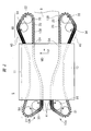
- FIG. 2 is a plan view showing a structural example of the stretching device shown in FIG.
- a plurality of links 20 arranged on the rails 13A and 13B are arranged in the oven shown in FIG. 2, but in FIG. 2, only the contours of the rails 13A and 13B and the film 8 are shown by dotted lines.
- FIG. 3 is an enlarged plan view showing one of the plurality of links shown in FIG. 2 in an enlarged manner.
- FIG. 4 is a cross-sectional view taken along the line AA of the link shown in FIG. FIG.
- FIG. 5 is a cross-sectional view taken along the line AB of the link shown in FIG.
- the members at positions different from the cross sections along the lines AA and AB shown in FIG. 3 are shown in white.
- the stretching device 5 has a pair of link devices 10A and 10B arranged apart from each other in a plan view.
- the film 8 is arranged between the link device 10A and the link device 10B, and is conveyed in the MD direction.
- the portion between the link device 10A and the link device 10B functions as a transport unit for transporting the film 8.
- the stretching device 5 covers the central portions of the pair of link devices 10A and 10B, and has a heat treatment section 12 for heat-treating the film 8.
- an example of heat treatment using an oven is shown as a heat treatment method.
- Each part (central portion 11) of the link devices 10A and 10B is arranged in the heat treatment section 12.
- each of the link devices 10A and 10B arranged so as to penetrate the oven which is the heat treatment unit 12 the portion arranged in the heat treatment unit 12 will be described as the central portion 11.
- the film 8 passes through the heat treatment section 12 while being held by the link devices 10A and 10B.
- Each of the link devices 10A and 10B has a plurality of links 20 connected so as to form an endless chain.
- a clip 21 (see FIG. 3), which is a jig for gripping the film 8, is attached to each of the plurality of links 20.
- the film 8 is gripped by a plurality of links 20 via clips 21.
- a plurality of links 20 connected to each other are mounted on the rails 13A and 13B in a state where they can travel along the rails 13A and 13B.
- Each of the link devices 10A and 10B has a pair of rails 13A and 13B.
- the rail 13A is arranged on the inner peripheral side and the rail 13B is arranged on the outer peripheral side.
- the rail 13A may be referred to as an inner rail, and the rail 13B may be referred to as an outer rail.
- each of the pair of link devices 10A and 10B includes a film side facing the film 8 and a return side located opposite to the film side.
- the side in which the plurality of links 20 are conveyed from the inlet side 8A to the outlet side 8B while the membrane 8 is gripped by the clip 21 is referred to as “membrane side”.
- the side that is located opposite to the membrane side, the clip 21 does not grip the membrane 8, and the plurality of links 20 are conveyed from the outlet side 8B toward the inlet side 8A is described as the "return side”.
- the endless chain composed of the plurality of links 20 is driven by a link drive mechanism arranged outside the heat treatment unit 12.
- the stretching device 5 has a link drive mechanism on each of the inlet side 8A and the outlet side 8B of the film 8.
- a sprocket 31 which is a first link driving mechanism is arranged on the inlet side 8A of the membrane 8.
- a sprocket 32 which is a second link driving mechanism, is arranged on the outlet side 8B of the film 8.
- the sprockets 31 and 32 are respectively engaged with a plurality of links 20 and rotate so as to send out the plurality of links 20 in the MD direction.
- Each of the plurality of links 20 moves on the rail 13A and the rail 13B by the driving force of the rotational operation of the sprockets 31 and 32.
- the pitch between the links 20 adjacent to each other (sometimes called the link pitch) can be changed according to the separation distance between the rail 13A and the rail 13B.
- the pitch of the links 20 adjacent to each other can be adjusted by adjusting the separation distance between the rail 13A and the rail 13B. Specifically, in the region where the distance between the rails 13A and 13B is large, the pitch of the adjacent links 20 is smaller than in the region where the distance between the rails 13A and 13B is small.
- the plurality of links 20 are arranged on the rail in a state where the pitches of the adjacent links 20 can be changed. Further, the clip 21 (see FIG. 3) is attached to one end of each of the plurality of links in a state in which the pitch (distance between centers) of adjacent clips 21 can be changed.
- the film 8 is stretched in the TD direction in the heat treatment section 12 in a region where the distance between the rail 13B of the link device 10A and the rail 13B of the link device 10B gradually increases.
- the stretching device 5 includes a region (MD direction stretching region) in the heat treatment unit 12 in which the link pitch of the plurality of links 20 included in the link device 10A and the link pitch of the plurality of links 20 included in the link device 10B are large.
- the film 8 is stretched in the MD direction in the region where the link pitch becomes large. In the region where the link pitch is large, the separation distance between the rail 13A and the rail 13B is small in each of the link devices 10A and 10B. Since the region where the distance between the rail 13B of the link device 10A and the rail 13B of the link device 10B gradually increases and the region where the link pitch increases are the same regions, the film 8 is moved in the TD direction and the MD direction in this region. It is stretched at the same time.
- the stretching device 5 increases the link pitch in the heat treatment section 12, it is necessary to reduce the link pitch at the inlet side 8A to the heat treatment section 12. Therefore, the stretching device 5 includes a sprocket 33 which is outside the heat treatment unit 12 and is arranged on the inlet side 8A of the film 8.
- the sprocket 33 rotates at a rotation speed slower than the rotation speed of the sprocket 31.
- the sprocket 33 engages the plurality of links 20.
- the sprocket 33 functions as a link adjusting mechanism unit for reducing the link pitch of the plurality of links 20.
- the stretching device 5 includes a sprocket 34 arranged on the outlet side 8B of the film 8 in addition to the sprocket 34.
- the sprocket 34 is located outside the heat treatment section 12 and on the inlet side 8A of the film 8.
- the sprocket 34 functions as a link adjusting mechanism unit for reducing the link pitch of the plurality of links 20 on the outlet side 8B of the film 8. The effect of providing the sprocket 34 will be described later.
- the film 8 is gripped by a clip 21 attached to the link 20 provided in each of the link devices 10A and 10B at the inlet side 8A to the heat treatment unit 12.
- the clip 21 is configured to open and close when the grip portion 21B (see FIGS. 4 and 5) moves up and down by a force such as the spring 21A shown in FIGS. 3 to 5.
- the clip 21 is conveyed in the MD direction together with the link 20 while gripping the end portion of the film 8.
- the film 8 is heated in the heat treatment section 12 and is stretched in the MD direction and the TD direction as the clip 21 moves.
- the stretched film 8 is conveyed toward the outlet side 8B of the heat treatment unit 12 while being gripped by the clip 21.
- the film 8 is removed from the clip 21 outside the heat treatment section 12 and at the outlet side 8B of the film 8.
- the take-up device 6 and the take-up device 7 shown in FIG. 1 are arranged at the tip of the outlet side of the film 8, and the stretched film 8 is taken up by the take-up device 7 and collected.
- the link 20 includes an upper link plate 22, a lower link plate 23, and rail holders 24 and 25.
- Each of the upper link plate 22 and the lower link plate 23 is a plate-shaped member that extends linearly in a plan view.
- a shaft 26 is inserted into one end of the upper link plate 22.
- the shaft 26 is also inserted into the lower link plate 23, and the upper link plate 22 and the lower link plate 23 are rotatable about the center of the shaft 26 as a rotation axis. It is connected via the shaft 26 in this state.
- a clip 21 is attached to one end of the lower link plate 23. As shown in FIG.
- increasing the angle of each ⁇ 1 shown in FIG. 3 may be referred to as “opening the link”, and decreasing the angle of the angle ⁇ 1 may be referred to as “closing the link”. Further, the operation of increasing or decreasing the angle of the angle ⁇ 1 may be referred to as “link opening / closing operation”.
- the shaft 27 is inserted into the upper link plate 22.
- the shaft 27 is a connecting member that connects the links 20 adjacent to each other.
- the shaft 27 is inserted into the upper link plate 22 of one link 20 and the lower link plate 23 of the other link 20 among the links 20 adjacent to each other.
- Each of the upper link plate 22 of one link 20 and the lower link plate 23 of the other link 20 are connected via the shaft 27 in a state of being rotatable around the center of the shaft 27 as a rotation axis.
- an engaging portion 29 that engages with the sprockets 31, 32, 33, and 34 shown in FIG. 2 is attached to the other end of the upper link plate 22.
- the shaft 27 is inserted between the engaging portion 29 and the shaft 26.
- the angle formed by the upper link plate 22 of one link 20 and the lower link plate 23 of the other link 20 (not shown). (Omitted) changes the angle.
- a rail holder 25 is attached to the lower end of the shaft 26.
- the rail holder 25 is attached in a rotatable state with the center of the shaft 26 as a rotation axis.
- a rail holder 24 is attached to the lower end of the shaft 27.
- the rail holder 24 is attached in a rotatable state with the center of the shaft 27 as the rotation axis.
- the rail holder 24 is arranged so as to cover the rail 13A
- the rail holder 25 is arranged so as to cover the rail 13B.
- the link 20 has the above structure, when the separation distance between the rail 13A and the rail 13B changes, the upper link plate 22 and the lower link plate 23 rotate in accordance with the change. As a result, the pitch of the adjacent links 20 changes according to the separation distance between the rail 13A and the rail 13B.
- the pitch of the adjacent links 20 can be defined with reference to the apex of the rotatably configured portion, in other words, the center of the shaft 26. That is, the pitch of the adjacent links 20 is defined as the distance between the centers of the shafts 26 included in each of the adjacent links 20.
- FIG. 6 is a flow chart showing an outline of the process flow of the link replacement method of the stretching device according to the present embodiment.
- the link exchange method will be described in order according to the flow shown in FIG.
- the stretching measure 5 described with reference to FIGS. 2 to 5 provides a link 20 to which a clip 21 (see FIGS. 3 to 5) for gripping the membrane 8 (see FIG. 2) is fixed.
- a link 20 By driving a plurality of links 20 connected in a variable state with a variable link pitch in an annular shape, the film 8 can be simultaneously stretched in two directions intersecting each other.
- the link 20 includes many moving parts, and the proper operation of the moving parts of the link 20 strongly affects the quality of the stretched film 8.
- the link 20 is repeatedly heated by passing through the inside of the heat treatment section 12, it is indispensable to replace consumable parts and the like. Therefore, from the viewpoint of stable operation of the stretching device 5, it is necessary to periodically replace a large number of links 20 to maintain the state in which the links 20 operate as designed.
- each of the link devices 10A and 10B shown in FIG. 2 has about 700 to 800 links 20. Therefore, it takes too much time to replace the links 20 one by one. Therefore, in order to improve work efficiency, it is preferable to replace the plurality of links 20 at once.
- a method of performing exchange work for each group will be described with 10 links (sometimes called 10 mountains) connected to each other as one group.
- the weight of one group of 10 links 20 connected is about 40 kg. Therefore, in consideration of the relationship between workability and work time, the number of links 20 included in one group is set to 10.
- the number of groups included in one group is not strictly limited to 10.
- the number of links 20 may be more than 10 as long as the workability of the replacement work is not impaired. Further, for example, even when one group is composed of a number of links 20 less than 10, the working time can be shortened as compared with exchanging one by one.
- the link exchange region 40 is provided outside the heat treatment unit 12 and on the return side of the outlet side 8B. Further, the link exchange region 40 is provided between the sprocket 34 and the heat treatment section 12 on the return side of the outlet side 8B.
- the inventor of the present application has studied a method of performing a link exchange operation in the region 41 on the film side of the inlet side 8A shown in FIG. In the case of the region 41, the separation distance between the link device 10A and the link device 10B is small, and a device for supplying the film 8 is arranged in the stretching device 5 shown in FIG. 1, so that it is difficult to secure a work space. is there. For example, as shown in FIG.
- the separation distance between the link device 10A and the link device 10B is smaller on the inlet side 8A of the membrane 8 than on the outlet side 8B of the membrane 8. Even if the replacement work can be performed, the work efficiency is low because the work needs to be performed in a limited space.
- the link exchange area 40 according to the present embodiment is arranged on the return side, there is less interference with other devices when performing the link exchange work as compared with the area 41. Therefore, a large work space can be secured. For example, when 10 links 20 connected to each other are exchanged at once, it is preferable that there is a large space for taking out the used links 20 and carrying in the replacement links 20. According to this embodiment, since the degree of freedom in handling the used or replacement link 20 is high, the work can be performed efficiently.
- FIG. 7 is a plan view showing a state in which a part of the plurality of links is disconnected in the link exchange area shown in FIG.
- FIG. 7 schematically shows an enlarged view of the link exchange area 40 of the link device 10A (see FIG. 2). Since the work in the link exchange area 40 of the link device 10B is the same as the work in the link exchange area 40 of the link device 10A, the illustration is omitted.
- the replacement work in the link device 10A will be exemplified.
- Each of the plurality of links 20 is connected via a shaft 27, and the connecting portion is fixed by inserting a pin 28 into the upper end portion of the shaft 27.
- the link 20A located at the beginning of the traveling direction and the pin 28 of the link 20B located at the end of the traveling direction are removed from the shaft 27.
- the upper link plate 22 (see FIG. 4) of the leading link 20A is removed from the shaft 27 inserted into the lower link plate 23 (see FIG. 4) of the front link 20C in the traveling direction.
- the take-out link group 20G1 is separated from the link 20C in front of the traveling direction.
- the upper link plate 22 of the link 20D located behind the take-out link group 20G1 is removed from the shaft 27 inserted into the lower link plate 23 of the last link 20B in the traveling direction.
- the take-out link group 20G1 is separated from the link 20D located behind in the traveling direction.
- FIG. 8 is a plan view schematically showing a state in which the take-out link group shown in FIG. 7 is bundled and carried out from the rail.
- the take-out link group 20G1 is bound by a band 42 made of a string or the like.
- FIG. 8 shows an example of binding by two bands 42, various modifications can be applied to the binding method.
- the plurality of links 20 are connected in a state where the link pitch can be freely changed. Therefore, if the take-out link group 20G1 is removed from the rail in an untied state, the individual links 20 will open and close freely due to the balance of gravity. Therefore, in the present embodiment, the opening / closing operation of the link 20 during transportation is restricted by binding the take-out link group 20G1.
- the angle ⁇ 1 formed by the upper link plate 22 and the lower link plate 23 shown in FIG. 3 is the smallest. In other words, it is preferable that the distance between the rail 13A and the rail 13B is the maximum in all the regions.
- the angle of the angle ⁇ 1 is the smallest, the upper link plate 22 and the lower link plate 23 of the link 20 are in a closed state. In this case, the plurality of links 20 can be tightened even if the binding work is performed on the rails 13A and 13B. As a result, the take-out link group 20G1 can be carried out with the degree of freedom of opening / closing operation limited.
- the separation distance between the rail 13A and the rail 13B is the largest among the link devices 10A and 10B as a whole.
- the separation distance between the rail 13A and the rail 13B in the link exchange region 40 is the separation distance between the rail 13A and the rail 13B in the region (second region) 41 between the sprocket 33 and the heat treatment portion 12 on the film side. Equal to the distance.
- Each of the link exchange area 40 and the area 41 is an area designed so that the pitch of the adjacent links 20 is the smallest among the areas of the link devices 10A and 10B.
- the bound take-out link group 20G1 is carried out of the link devices 10A and 10B (see FIG. 2).
- a transport device such as a chain block may be used.
- a large work space can be secured around the link exchange area 40 of the present embodiment, even a large transport device can be used.
- the taken-out link group 20G1 is subjected to inspection of the worn state, disassembled as necessary, and repaired or parts are replaced.
- the link 20 is exchanged in the area 41, the sprocket 34 and the link exchange area 40 shown in FIG. 2 are unnecessary.
- the return side of the link devices 10A and 10B is not provided with a mechanism for reducing the link pitch, and the link 20 connected to the inlet side 8A of the film 8 may be driven with the link pitch wide.
- the total number of links 20 can be reduced as compared with the present embodiment.
- the link exchange area 40 is provided on the return side and on the outlet side 8B of the film 8. As a result, even if the total number of links 20 to be exchanged increases, the efficiency of the exchange work is improved as a result.
- the link exchange area 40 on the inlet side 8A of the membrane 8 causes the following problems. That is, when the link pitch is small, it is difficult to drive the link 20 from the return side to the film side using the sprocket 31. Therefore, in order to provide the link exchange area 40 on the inlet side 8A of the membrane 8, a mechanism for widening the link pitch (for example, another sprocket or rail (not shown)) is provided between the link exchange area 40 and the sprocket 31. More space is needed.
- the link exchange region 40 when the link exchange region 40 is provided on the outlet side 8B of the film 8, the rail 13A and the rail 13B are in the path of transporting the link 20 from the outlet side 8B to the inlet side 8A.
- the link pitch can be increased by reducing the separation distance of. Therefore, the return side of the outlet side 8B, which is a place where it is possible to secure a work space in which the link replacement work can be efficiently performed while suppressing the increase in size of the stretching device 5, is the optimum place for the link replacement area 40. Is considered to be.
- FIG. 9 is a plan view schematically showing a state in which the replacement link group is carried onto the rail of the link exchange region shown in FIG.
- the replacement link group 20G2 carried in in this step is composed of the same 10 links 20 as the take-out link group 20G1 carried out in the carry-out process described with reference to FIG.
- the replacement link group 20G2 is bound by a band 42 made of a string or the like.
- the fact that various modifications can be applied to the binding method is the same as the carrying-out process described with reference to FIG.
- the replacement link group 20G2 in addition to limiting the opening / closing operation during transportation, the replacement link group 20G2 needs to be tied in order to easily align the rails 13A and 13B.
- each of the plurality of links 20 includes rail holders 24 and 25, respectively.
- the rail holder 24 is arranged so as to sandwich the rail 13A
- the rail holder 25 is arranged so as to sandwich the rail 13B.
- the ten links 20 are collectively mounted on the rails 13A and 13B. Therefore, in order to easily align the rail holders 24 and 25 with the rails 13A and 13B, the rail 13A and the rail 13B extend in parallel in the link exchange area 40, and 10 links are provided. It is preferable that the open / closed states of 20 are easily aligned. The open / closed states of the 10 links 20 are easily aligned when each ⁇ 1 shown in FIG. 3 is the smallest.
- the replacement link group 20G2 in which a plurality of links 20 are bound in advance is prepared and mounted on the rails 13A and 13B in the bound state.
- the separation distance between the rail 13A and the rail 13B is the largest among the regions of the link devices 10A and 10B. Therefore, the rail holders 24 and 25 of the replacement link group 20G2 in the bundled state and the rails 13A and 13B can be easily aligned.
- the angle of each ⁇ 1 shown in FIG. 3 is the largest, in other words, the separation distance between the rail 13A and the rail 13B. Is the smallest, and more specifically, the positions can be aligned even when each of the plurality of links 20 is opened to the maximum.
- the length of the replacement link group 20G2 becomes long, so that it is difficult to bind the 10 links 20 in that state. Therefore, it is particularly preferable to carry in the plurality of links 20 in the most closed state as in the present embodiment.
- FIG. 10 is a plan view showing a state in which the band of the replacement link group shown in FIG. 9 is removed and connected to the front link.
- the through hole formed in the upper link plate 22 (see FIG. 4) of the link 20A located at the head in the traveling direction is formed.
- the shaft 27 to be inserted into the lower link plate 23 (see FIG. 4) of the link 20C in the front in the traveling direction is inserted.
- a washer plate that prevents the shaft 27 from coming off from the through hole of the upper link plate 22 is inserted, and a pin 28 is inserted into the shaped end portion of the shaft 27 to fix the shaft 27.
- the replacement link group 20G2 is connected to the link 20C in front of the traveling direction.
- connection release step to the delivery step are repeatedly executed. Therefore, in the connecting process, the link 20B located at the end of the traveling direction and the link 20D located behind the traveling direction are not connected until the replacement of all the links 20 is completed.
- all the links 20 are exchanged, they are inserted into the lower link plate 23 (see FIG. 4) of the link 20B located at the end in the traveling direction among the exchange link group 20G2 composed of 10 links 20.
- a through hole formed in the upper link plate 22 (see FIG. 4) of the link 20D rearward in the traveling direction is inserted into the shaft 27.
- the replacement link group 20G2 shown in FIG. 10 is sent toward the heat treatment section 12 side shown in FIG. 2, and a new take-out link group 20G1 (see FIG. 7) is in the link replacement area.
- a new take-out link group 20G1 (see FIG. 7) is in the link replacement area.
- the link 20 located behind the replacement link group 20G2 becomes the link 20A located at the head of the next extraction link group 20G1 in the traveling direction.
- a plurality of links 20 can be sent out by driving each of the sprockets 31 to 34 shown in FIG.
- connection release step to the sending step are repeatedly carried out. As a result, when all the links 20 included in the link devices 10A and 10B shown in FIG. 2 are replaced, the replacement is completed.
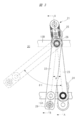
- FIG. 11 is an enlarged plan view of one outlet side of the pair of link devices shown in FIG.
- the sprocket 31 arranged on the inlet side 8A shown in FIG. 2 corresponds to the sprocket 32 on the outlet side 8B
- the sprocket 33 corresponds to the sprocket 34. Since the sprockets 31 and 33 have the same structure as the sprockets 32 and 34 and operate in the same manner, they will be omitted from the illustration and will be described with reference to FIG. 2 as necessary.
- sprockets 31 to 34 are used as the link driving mechanism and the link adjusting mechanism.
- the sprockets 31 to 34 are gears having a plurality of teeth and are driven by a motor (not shown).
- the sprockets 31 to 34 may be independently driven by a motor, but some sprockets may also be used as one motor.
- the sprockets 32 and 34 may be driven by one motor, or the sprockets 32 and 34 may be driven independently by different motors.
- the sprockets 32 and 34 are driven by one motor, it is easy to synchronize the rotation of each sprocket.
- the rotation speed of each sprocket can be controlled individually, so that the adjustment margin is large.
- the sprocket 31 and the sprocket 32 as the link drive mechanism of the link devices 10A and 10B shown in FIG. 2 define the transport speed of the film 8.
- the sprocket 31 rotates so as to send out a plurality of links 20 from the return side of each of the pair of link devices 10A and 10B toward the film side.
- the sprocket 32 rotates so as to send out a plurality of links 20 from the film side of each of the pair of link devices 10A and 10B toward the return side.
- the sprockets 31 and 32 have the same structure as each other. Specifically, the sprockets 31 and 32 have the same rotation diameter (distance from the center of rotation to the tip of the tooth) and the number of teeth. Further, the sprockets 31 and 32 rotate at the same rotation speed.
- the sprocket 34 that functions as a link adjusting mechanism for reducing the pitch of the plurality of links 20 is a rotating body that rotates so that the pitch of the plurality of links 20 becomes smaller at the outlet side 8B shown in FIG.
- the pitch of adjacent links 20 can be reduced by increasing the distance between the rails 13A and 13B facing each other.
- the link 20 may not move smoothly on the rails, which may cause troubles such as a part of the links 20 being clogged with a part of the rails. .. Therefore, when the rotating body (sprocket 34) that assists the adjustment of the link pitch is not used as in the present embodiment, a long distance is taken between the sprocket 32 and the link exchange area 40 and the links are gradually linked. It is necessary to reduce the pitch.
- the sprocket 34 has a plurality of links 20 from the outlet side 8B of the membrane 8 (see FIG. 2) toward the inlet side 8A (see FIG. 2) of the membrane 8. Rotate to send out.
- the sprocket 34 rotates at a rotation speed slower than the rotation speed of the sprocket 32.
- the number of teeth of the sprocket 34 is larger than the number of teeth of the sprocket 32. In the example shown in FIG. 11, the number of teeth of the sprocket 34 is about 5 times the number of teeth of the sprocket 32.
- the engaging portions 29 see FIGS.
- the sprocket 34 for reducing the link pitch is arranged in the region where the separation distance between the rail 13A and the rail 13B suddenly increases.
- the sprocket 34 forcibly sends the engaging portion 29 of the link 20 forward.
- the speed at which the sprocket 34 sends the link 20 forward is controlled by the rotation speed of the sprocket 34. Therefore, each of the plurality of links 20 is smoothly driven forward (entrance side) on the rail 13A without causing clogging.
- the rail holder 25 (see FIG. 4) sandwiching the rail 13B gradually decelerates following the deceleration of the rail holder 24. Then, the link 20 can be closed (in other words, the angle of each ⁇ 1 shown in FIG. 3 is minimized) before reaching the link exchange area 40.
- the sprocket 34 assists the link pitch adjustment function by changing the separation distance of the pair of rails. As a result, as shown in FIG. 11, the link 20 can be driven without clogging even when the link pitch is sharply reduced in the portion in contact with the sprocket 34.
- the rotation diameter of the sprocket 34 (distance from the center of rotation to the tip of the tooth) is equal to the rotation diameter of the sprocket 32. Therefore, the ratio of the rotational speeds of the sprockets 32 and 34 is inversely proportional to the ratio of the number of teeth of the sprockets 32 and 34. For example, in the example shown in FIG. 11, since the number of teeth of the sprocket 32 is 1/5 of the number of teeth of the sprocket 34, the rotation speed of the sprocket 32 is 5 times the rotation speed of the sprocket 34.
- the number of teeth of the sprocket 33 shown in FIG. 2 is equal to the number of teeth of the sprocket 34.
- the rotation diameter and rotation speed of the sprocket 33 are equal to the rotation diameter and rotation speed of the sprocket 34.
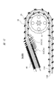
- FIG. 12 is an enlarged plan view showing a modified example of the link adjusting mechanism shown in FIG.
- the stretching device 5A of the modified example shown in FIG. 12 uses a screw (link adjusting mechanism) 35 as a link adjusting mechanism for reducing the link pitch of the plurality of links 20, and the stretching device 5 shown in FIG. 2 is used. Is different from.
- the screw 35 includes a shaft 35A extending along the rail 13A and a plurality of wings 35B provided around the shaft 35A.
- the screw 35 is a rotating body that rotates about the center of the shaft 35A as a rotation axis.
- a plurality of wings 35B attached so as to be inclined with respect to the rotation axis rotate.
- the engaging portion 29 (see FIGS. 3 and 4) of the link 20 is engaged with the groove between the adjacent wings 35B.
- the screw 35 rotates so as to feed out a plurality of links 20 from the outlet side 8B of the membrane 8 (see FIG. 2) toward the inlet side 8A (see FIG. 2) of the membrane 8.
- the screw 35 rotates at a rotation speed slower than the rotation speed of the sprocket 32.
- the engaging portion 29 included in each of the plurality of links 20 being conveyed is engaged with the groove between the adjacent wings 35B. Further, as shown in FIG. 12, the plurality of wings 35B of the screw 35 are attached so that the pitch of the engaging portions 29 (see FIGS. 3 and 4) gradually decreases in the extending direction of the shaft 35A. There is. Also in the case of this modification, the separation distance between the rail 13A and the rail 13B sharply increases in this region. At this time, since the rail 13A arranged inside has a smaller turning radius than the rail 13B arranged outside, the rail holder in the inner part of the link 20 (around the rail holder 24 shown in FIGS. 3 and 4). 24 is easily clogged.
- the screw 35 for reducing the link pitch is arranged in the region where the separation distance between the rail 13A and the rail 13B suddenly increases.
- the screw 35 forcibly sends the engaging portion 29 of the link 20 forward.
- the speed at which the screw 35 sends the link 20 forward is controlled by the rotation speed of the screw 35. Therefore, each of the plurality of links 20 is smoothly driven forward (entrance side) on the rail 13A without causing clogging.
- the rail holder 25 (see FIG. 4) sandwiching the rail 13B gradually decelerates following the deceleration of the rail holder 24 (see FIG. 4). Then, the link 20 can be closed (in other words, the angle of each ⁇ 1 shown in FIG. 3 is minimized) before reaching the link exchange area 40.
- the screw 35 assists the link pitch adjustment function by changing the separation distance of the pair of rails.
- the link 20 can be driven without clogging even when the link pitch is sharply reduced in the portion in contact with the screw 35.
- the stretching device 5A of this modified example in the case of the stretching device 5A of this modified example, the area occupied by the device on the outlet side 8B of the film 8 (see FIG. 2) can be further reduced. Further, the total extension distances of the rails 13A and 13B are shorter than those shown in the example shown in FIG. As a result, the total number of required links 20 can be reduced.
- the stretching device 5A shown in FIG. 12 is the same as the stretching device 5 described with reference to FIGS. 1 to 11 except for the above-mentioned differences. Therefore, the duplicate description will be omitted.
- the total number of links 20 included in the stretching device the weight of 10 links 20, the ratio of the rotation speeds of the sprocket, and the like have been exemplified.
- each numerical value is not limited to the mentioned numerical value as long as it does not deviate from the gist of the described invention.
Landscapes
- Engineering & Computer Science (AREA)
- Mechanical Engineering (AREA)
- Physics & Mathematics (AREA)
- Thermal Sciences (AREA)
- Health & Medical Sciences (AREA)
- Oral & Maxillofacial Surgery (AREA)
- Manufacturing & Machinery (AREA)
- Shaping By String And By Release Of Stress In Plastics And The Like (AREA)
Abstract
膜の延伸装置は以下を含む。膜の搬送および延伸可能な、複数のリンクが無端チェーンを構成するように連結された一対の第1および第2リンク装置。第1および第2リンク装置の中央部を覆う、膜に熱処理を行うための熱処理部。熱処理部の外部であって、膜の入口側に配置された、複数のリンクを駆動するためのスプロケット(第1のリンク駆動機構)。熱処理部の外部であって、膜の出口側に配置された、複数のリンクを駆動するためのスプロケット(第2のリンク駆動機構)。熱処理部の外部であって、膜の出口側に配置された、複数のリンクのピッチを小さくするためのスプロケット(リンク調整機構)。
Description
本発明は、膜を縦方向および横方向に引き延ばす延伸装置に好適に利用できるものである。
延伸装置においては、縦延伸と横延伸を行うことができ、これらを順番に行うことを逐次二軸延伸法といい、一度に行うことを同時二軸延伸法という。同時二軸延伸法は、逐次延伸法に比べ、スクラッチが発生しにくい、原料の適応範囲が広く、結晶化速度が速くても延伸可能である、物性の縦横均一性が高いなどのメリットがある。
例えば、特許文献1(特開2004-155138号公報)には、折尺状に形成された複数個の等長リンク装置よりシート状物の両側端に配置された無端リンク装置を、シート状物の入口側及び出口側のスプロケットにより駆動し、進行方向に末広がり状に配置されたガイドで形成されるガイドレールによって案内し、シート状物を横方向に延伸させるシート状物の延伸機が開示されている。
膜を引き延ばす延伸装置は、無端チェーンを構成するように連結された、複数のリンクを有する。例えばメンテナンス時に、この複数のリンクの交換作業を行う場合、作業の効率化の観点から改善の余地がある。
その他の課題と新規な特徴は、本明細書の記述および添付図面から明らかになるであろう。
本願において開示される膜の延伸装置は、以下を含む。前記膜の搬送および延伸可能な、複数のリンクが無端チェーンを構成するように連結された一対のリンク装置;
前記一対のリンク装置の中央部を覆う、前記膜に熱処理を行うための熱処理部;前記熱処理部の外部であって、前記膜の入口側に配置された、前記複数のリンクを駆動するための第1のリンク駆動機構;
前記熱処理部の外部であって、前記膜の出口側に配置された、前記複数のリンクを駆動するための第2のリンク駆動機構;
前記熱処理部の外部であって、前記膜の出口側に配置された、前記複数のリンクのピッチを小さくするためのリンク調整機構部。
前記一対のリンク装置の中央部を覆う、前記膜に熱処理を行うための熱処理部;前記熱処理部の外部であって、前記膜の入口側に配置された、前記複数のリンクを駆動するための第1のリンク駆動機構;
前記熱処理部の外部であって、前記膜の出口側に配置された、前記複数のリンクを駆動するための第2のリンク駆動機構;
前記熱処理部の外部であって、前記膜の出口側に配置された、前記複数のリンクのピッチを小さくするためのリンク調整機構部。
本願において開示される延伸装置によれば、複数のリンクを効率的に交換することができる。
以下、実施の形態を実施例や図面に基づいて詳細に説明する。なお、実施の形態を説明するための全図において、同一の機能を有する部材には同一の符号を付し、その繰り返しの説明は省略する。
<全体構造>
図1は、本実施の形態の薄膜の製造システムの構成を示す模式図である。図1に示す本実施の形態の薄膜製造システム1は、混練押し出し装置(二軸混練押し出し装置)2、Tダイ3、原反冷却装置4、延伸装置(同時二軸延伸装置)5、引き取り装置6、および巻き取り装置7を有する。図1に示す例では、まず、混練押し出し装置2の原料供給部2Aに樹脂材料(ペレット)および添加剤などを供給する。二軸混練押し出し装置2は、供給された樹脂材料などを、混合しながら輸送(搬送)する。Tダイ3は、二軸混練押し出し装置2により混練された混練物(溶融樹脂)をスリットから押し出す。Tダイ3から押し出された混練物は、原反冷却装置4において冷却され、膜(シート、樹脂膜)8になる。Tダイ3により成形される膜は、延伸装置5に連続的に供給される。延伸装置5にとっては、膜8は延伸に供される原料に相当する。本明細書では、延伸装置5を中心に説明するので、延伸装置5に供されるシート状の材料、および延伸処理が施されている前の膜8のことを原反と呼ぶ場合がある。一方、延伸処理が完了し、延伸装置5から排出された状態の膜8を薄膜と呼ぶ場合がある。
図1は、本実施の形態の薄膜の製造システムの構成を示す模式図である。図1に示す本実施の形態の薄膜製造システム1は、混練押し出し装置(二軸混練押し出し装置)2、Tダイ3、原反冷却装置4、延伸装置(同時二軸延伸装置)5、引き取り装置6、および巻き取り装置7を有する。図1に示す例では、まず、混練押し出し装置2の原料供給部2Aに樹脂材料(ペレット)および添加剤などを供給する。二軸混練押し出し装置2は、供給された樹脂材料などを、混合しながら輸送(搬送)する。Tダイ3は、二軸混練押し出し装置2により混練された混練物(溶融樹脂)をスリットから押し出す。Tダイ3から押し出された混練物は、原反冷却装置4において冷却され、膜(シート、樹脂膜)8になる。Tダイ3により成形される膜は、延伸装置5に連続的に供給される。延伸装置5にとっては、膜8は延伸に供される原料に相当する。本明細書では、延伸装置5を中心に説明するので、延伸装置5に供されるシート状の材料、および延伸処理が施されている前の膜8のことを原反と呼ぶ場合がある。一方、延伸処理が完了し、延伸装置5から排出された状態の膜8を薄膜と呼ぶ場合がある。
原反冷却装置4で冷却されて形成された膜8は、延伸装置5によりMD方向およびTD方向に延伸され、薄膜になる。延伸された膜8は、引き取り装置6を介して巻き取り装置7に巻き取られる。
図1に一例として示す薄膜製造システム1の場合、上記のように、薄膜を製造する。なお、図1に示す薄膜製造システム1は、形成する薄膜の特性に応じて、種々の変形が可能である。例えば、図1に示す構成に加え、図1に示す引き取り装置6の近傍に図示しない抽出槽が設けられ、膜8中の可塑剤(例えば、パラフィンなど)が抽出槽で除去される場合がある。
本実施の形態の延伸装置5は、膜8をMD方向に搬送しながら、薄膜をMD方向およびTD方向に引き延ばす。MD(Machine Direction)方向は、薄膜の搬送方向であり、縦方向とも言う。また、TD(Transverse Direction)方向は、上記薄膜の搬送方向と交差する方向であり、横方向とも言う。互いに交差する二方向に同時に延伸させることが可能な延伸装置5は、同時二軸延伸装置と呼ばれる。
以下、延伸装置5の構造、および延伸装置5が、MD方向およびTD方向に膜8を引き延ばす原理について説明する。図2は、図1に示す延伸装置の構造例を示す平面図である。図2に示すオーブン内には、レール13A、13B上に配置された複数のリンク20が配置されるが、図2では、レール13Aおよび13B、および膜8の輪郭のみを、点線で示している。図3は、図2に示す複数のリンクのうちの一つを拡大して示す拡大平面図である。図4は、図3に示すリンクのA-A線に沿った断面図である。図5は、図3に示すリンクのA-B線に沿った断面図である。図4および図5では、クリップ21の支持構造を見やすくするため、図3に示すA-A線およびA-B線に沿った断面とは異なる位置にある部材を、白抜きで示している。
図2に示すように、延伸装置5は、平面視において、互いに離間して配置される一対のリンク装置10Aおよび10Bを有する。膜8は、リンク装置10Aとリンク装置10Bとの間に配置され、MD方向に搬送される。リンク装置10Aとリンク装置10Bとの間の部分は、膜8を搬送するための搬送部として機能する。延伸装置5は、一対のリンク装置10Aおよび10Bの中央部を覆い、膜8に熱処理を行うための熱処理部12を有する。図2に示す例では、熱処理の方法として、オーブンを用いた熱処理の例を示している。リンク装置10Aおよび10Bのそれぞれの一部分(中央部11)は、熱処理部12の庫内に配置される。以下、本明細書では、熱処理部12であるオーブンを貫通するように配置されるリンク装置10Aおよび10Bのそれぞれのうち、熱処理部12内に配置された部分を中央部11として説明する。膜8は、リンク装置10Aおよび10Bに保持された状態で、熱処理部12を通過する。
リンク装置10Aおよび10Bのそれぞれは、無端チェーンを構成するように連結された複数のリンク20を有する。複数のリンク20のそれぞれには、膜8を把持する治具であるクリップ21(図3参照)が取り付けられている。膜8は、クリップ21を介して複数のリンク20に把持される。
互いに連結された複数のリンク20は、レール13Aおよび13Bに沿って走行可能な状態で、レール13Aおよび13B上に載せられる。リンク装置10Aおよび10Bのそれぞれは、一対のレール13Aおよび13Bを有する。一対のレール13Aおよび13Bのうち、レール13Aは内周側に、レール13Bは外周側に、それぞれ配置される。なお、レール13Aを内側レールと呼び、レール13Bを外側レールと呼ぶ場合がある。
図2に示すようにリンク装置10Aおよび10Bのそれぞれが備える一対のレール13Aおよび13Bは、膜8の入口側(入口部)8A、熱処理部12、および出口側(出口部)8Bに亘って環状に形成される。一対のリンク装置10Aおよび10Bのそれぞれは、膜8と対向する膜側と、膜側の反対に位置するリターン側と、を備える。以下の説明において、膜8がクリップ21により把持した状態で、複数のリンク20が入口側8Aから出口側8Bに向かって搬送されるサイドを「膜側」と記載する。一方、膜側の反対に位置し、クリップ21が膜8を把持せず、複数のリンク20が出口側8Bから入口側8Aに向かって搬送されるサイドを「リターン側」と記載する。
複数のリンク20により構成される無端チェーンは、熱処理部12の外側に配置されるリンク駆動機構により駆動される。図2に示す例では、延伸装置5は、膜8の入口側8Aおよび出口側8Bのそれぞれにリンク駆動機構を有する。膜8の入口側8Aには、第1のリンク駆動機構であるスプロケット31が配置される。膜8の出口側8Bには、第2のリンク駆動機構であるスプロケット32が配置される。スプロケット31および32は、それぞれ複数のリンク20に係合され、複数のリンク20をMD方向に送り出すように回転する。複数のリンク20のそれぞれは、スプロケット31および32の回転動作の駆動力により、レール13Aおよびレール13B上を移動する。
複数のリンク20のうち、互いに隣り合うリンク20間のピッチ(リンクピッチと呼ぶ場合もある)は、レール13Aとレール13Bとの離間距離に応じて変更可能である。言い換えれば、レール13Aとレール13Bとの離間距離を調整することにより、互いに隣り合うリンク20のピッチを調整することができる。詳しくは、レール13Aと13Bとの離間距離が大きい領域では、レール13Aと13Bとの離間距離が小さい領域と比較して、隣り合うリンク20のピッチが小さい。
複数のリンク20は、隣り合うリンク20のピッチが変更可能な状態でレール上に配置される。また、クリップ21(図3参照)は、隣り合うクリップ21のピッチ(中心間距離)が変更可能な状態で複数のリンクのそれぞれの一方の端部に取り付けられる。膜8は、熱処理部12において、リンク装置10Aのレール13Bとリンク装置10Bのレール13Bとの離間距離が徐々に大きくなる領域で、TD方向に延伸される。延伸装置5は、熱処理部12において、リンク装置10Aが備える複数のリンク20のリンクピッチ、およびリンク装置10Bが備える複数のリンク20のリンクピッチが大きくなる領域(MD方向延伸領域)を備える。膜8は、このリンクピッチが大きくなる領域において、MD方向に延伸される。リンクピッチが大きくなる領域では、リンク装置10Aおよび10Bのそれぞれにおいて、レール13Aとレール13Bとの離間距離が小さくなる。リンク装置10Aのレール13Bとリンク装置10Bのレール13Bとの離間距離が徐々に大きくなる領域とリンクピッチが大きくなる領域とは同じ領域なので、この領域では、膜8は、TD方向およびMD方向に同時に延伸される。
また、延伸装置5は、熱処理部12において、リンクピッチを大きくするので、熱処理部12への入口側8Aにおいて、リンクピッチを小さくしておく必要がある。このため、延伸装置5は、熱処理部12の外部であって、膜8の入口側8Aに配置されたスプロケット33を備える。スプロケット33は、スプロケット31の回転速度より遅い回転速度で回転する。スプロケット33は、複数のリンク20に係合する。スプロケット31の回転速度より遅く回転するスプロケット33が膜8の入口側8Aに配置されることにより、複数のリンク20のリンクピッチは、スプロケット33に係合される領域において小さくなる。スプロケット33は、複数のリンク20のリンクピッチを小さくするためのリンク調整機構部として機能する。
また、延伸装置5は、スプロケット34の他に、膜8の出口側8Bに配置されるスプロケット34を備える。スプロケット34は、熱処理部12の外部であって、膜8の入口側8Aに配置される。スプロケット34は、膜8の出口側8Bにおいて、複数のリンク20のリンクピッチを小さくするためのリンク調整機構部として機能する。スプロケット34が設けられることによる効果は後述する。
膜8は、熱処理部12への入口側8Aにおいて、リンク装置10Aおよび10Bのそれぞれが備えるリンク20に取り付けられたクリップ21により把持される。クリップ21は、図3~5に記載されるバネ21Aなどの力により把持部21B(図4および5参照)が上下に動作することで、開閉するように構成される。クリップ21は膜8の端部を把持した状態でリンク20と一緒にMD方向に搬送される。膜8は、熱処理部12内で加熱され、かつ、クリップ21の移動に伴ってMD方向およびTD方向に引き伸ばされる。引き伸ばされた後の膜8は、クリップ21に把持された状態で、熱処理部12の出口側8Bに向かって搬送される。熱処理部12の外部であり、かつ膜8の出口側8Bにおいて、膜8はクリップ21から外される。膜8の出口側の先には、図1に示す引き取り装置6および巻き取り装置7が配置され、引き伸ばされた膜8は、巻き取り装置7に巻き取られ、回収される。
次に、リンク20の構造について説明する。図3に示すように、リンク20は、上段側リンクプレート22と、下段側リンクプレート23と、レールホルダ24および25と、を備える。上段側リンクプレート22および下段側リンクプレート23のそれぞれは、平面視において直線的に延びる板状の部材である。上段側リンクプレート22の一方の端部には、シャフト26が挿入される。図4および図5に示すように、シャフト26は、下段側リンクプレート23にも挿入され、上段側リンクプレート22と、下段側リンクプレート23とは、シャフト26の中心を回転軸として、回転自在な状態でシャフト26を介して連結される。下段側リンクプレート23の一方の端部には、クリップ21が取り付けられる。図4に示すように、下段側リンクプレート23において、シャフト26は、クリップ21が取り付けられる一方の端部と他方の端部との間に挿入される。図3では、シャフト26を中心に上段側リンクプレート22と下段側リンクプレート23とが回転する状態を、二点鎖線を用いて模式的に示している。シャフト26を回転軸として上段側リンクプレート22と下段側リンクプレート23とが回転すると、上段側リンクプレート22と下段側リンクプレート23との成す角θ1の角度が変化する。
なお、本明細書では、図3に示す各θ1の角度が大きくなることを「リンクが開く」、角θ1の角度が小さくなることを「リンクが閉じる」と呼ぶ場合がある。また、角θ1の角度が大きくなったり小さくなったりする動作を、「リンクの開閉動作」と呼ぶ場合がある。
また、図4および図5に二点鎖線で示すように、上段側リンクプレート22には、シャフト27が挿入される。シャフト27は、互いに隣り合うリンク20を連結する連結部材である。シャフト27は、互いに隣り合うリンク20のうち、一方のリンク20の上段側リンクプレート22と、他方のリンク20の下段側リンクプレート23とに挿入される。一方のリンク20の上段側リンクプレート22および他方のリンク20の下段側リンクプレート23のそれぞれは、シャフト27の中心を回転軸として回転自在な状態で、シャフト27を介して連結される。図5に示すように、上段側リンクプレート22の他方の端部には、図2に示すスプロケット31、32、33、および34に係合される係合部29が取り付けられる。上段側リンクプレート22において、シャフト27は、係合部29とシャフト26との間に挿入される。シャフト27を回転軸として上段側リンクプレート22と下段側リンクプレート23とが回転すると、一方のリンク20の上段側リンクプレート22と他方のリンク20の下段側リンクプレート23との成す角(図示は省略)の角度が変化する。
図4および図5に示すように、シャフト26の下端には、レールホルダ25が取り付けられる。レールホルダ25は、シャフト26の中心を回転軸として、回転可能な状態で取り付けられる。図4に示すように、シャフト27の下端には、レールホルダ24が取り付けられる。レールホルダ24は、シャフト27の中心を回転軸として、回転可能な状態で取り付けられる。レールホルダ24はレール13Aを覆うように配置され、レールホルダ25はレール13Bを覆うように配置される。
リンク20は、上記の構造を備えるので、レール13Aとレール13Bとの離間距離が変化すると、その変化に追従して上段側リンクプレート22および下段側リンクプレート23が回転する。この結果、隣り合うリンク20のピッチは、レール13Aとレール13Bとの離間距離に対応して変化する。なお、隣り合うリンク20のピッチは、回転可能に構成された部分の頂点、言い換えれば、シャフト26の中心を基準として規定することができる。すなわち、隣り合うリンク20のピッチとは、互いに隣り合うリンク20のそれぞれが備えるシャフト26の中心間距離として規定される。
<リンクの交換方法>
次に、図2に示す延伸装置5が備える複数のリンク20の交換方法について説明する。図6は、本実施の形態の延伸装置のリンクの交換方法の工程フローの概要を示すフロー図である。以下では、図6に示すフローに沿ってリンクの交換方法を順に説明する。
次に、図2に示す延伸装置5が備える複数のリンク20の交換方法について説明する。図6は、本実施の形態の延伸装置のリンクの交換方法の工程フローの概要を示すフロー図である。以下では、図6に示すフローに沿ってリンクの交換方法を順に説明する。
図2~図5を用いて説明した延伸措置5は、膜8(図2参照)を把持するクリップ21(図3~5参照)が固定されたリンク20を供える。リンクピッチが可変な状態で連結された複数のリンク20を環状に駆動することにより、膜8を互いに交差する2方向に同時に延伸させることができる。延伸装置5を安定的に稼働させるためには、延伸装置5の構成部品の定期的なメンテナンスが必要である。特に、リンク20は可動部を多く含みリンク20の可動部が適切に動作することが、延伸された膜8の品質に強く影響する。また、リンク20は、熱処理部12の庫内を通過することで繰り返し加熱されるので、消耗部品の交換等が必要不可欠である。このため、延伸装置5の安定稼働の観点から、多数のリンク20を定期的に交換し、リンク20が設計通りに動作する状態を維持する必要がある。
ところが、一台の延伸装置5が備えるリンク20の数は、1000個を超える。例えば、図2に示すリンク装置10Aおよび10Bのそれぞれが700個~800個程度のリンク20を有している。このため、リンク20を一個ずつ交換していては、作業時間がかかりすぎる。したがって、作業効率を向上させるためには、複数個のリンク20を一括で交換することが好ましい。
例えば、以下で説明する実施の形態では、互いに連結された10個(10山と呼ぶ場合もある)のリンク20を1グループとして、グループ毎に交換作業を行う方法について説明する。10個のリンク20が連結された一つのグループの重量は、約40kgである。このため、作業性と作業時間との関係を勘案して、一つのグループに含まれるリンク20の数を10個とした。ただし、一つのグループに含まれるグループの数は厳密に10個に限定されない。交換作業の作業性が損なわれない範囲であれば、リンク20の数は10個より多くてもよい。また、例えば一つのグループが10個より少ない数のリンク20により構成される場合でも、1個ずつ交換するよりは作業時間を短縮できる。
(カバー取り外し工程)
まず、図6に示すカバー取り外し工程として、リンク装置10Aおよび10Bのそれぞれを覆うカバーのうち、リンク交換作業の作業領域であるリンク交換領域(第1領域)40(図2参照)を覆う部分のカバーを取り外し、リンク交換領域40の複数のリンク20を露出させる。図2では図示を省略したが、複数のリンク20のそれぞれは、膜8の入口側8Aおよび出口側8Bのそれぞれにおいて、リンク装置10Aおよび10Bのカバーに覆われている。
まず、図6に示すカバー取り外し工程として、リンク装置10Aおよび10Bのそれぞれを覆うカバーのうち、リンク交換作業の作業領域であるリンク交換領域(第1領域)40(図2参照)を覆う部分のカバーを取り外し、リンク交換領域40の複数のリンク20を露出させる。図2では図示を省略したが、複数のリンク20のそれぞれは、膜8の入口側8Aおよび出口側8Bのそれぞれにおいて、リンク装置10Aおよび10Bのカバーに覆われている。
本実施の形態の場合、リンク交換領域40は、熱処理部12の外部で、かつ、出口側8Bのリターン側に設けられている。また、リンク交換領域40は、出口側8Bのリターン側において、スプロケット34と熱処理部12との間に設けられている。本実施の形態に対応する検討例として、本願発明者は、図2に示す入口側8Aの膜側にある領域41において、リンク交換作業を行う方法について検討した。領域41の場合、リンク装置10Aとリンク装置10Bとの離間距離が小さく、かつ、図1に示す延伸装置5に膜8を供給するための装置が配置されるため、作業スペースの確保が困難である。例えば、図2に示すように、リンク装置10Aとリンク装置10Bとの離間距離は、膜8の入口側8Aの方が膜8の出口側8Bより小さい。仮に、交換作業ができたとしても、限られたスペースで作業を行う必要があるので、作業効率が低い。
一方、本実施の形態によるリンク交換領域40は、リターン側に配置されているので、領域41と比較して、リンク交換作業を行う際の他の装置との干渉が少ない。このため、広い作業スペースを確保することができる。例えば、互いに連結された10個のリンク20を一括して交換する場合、使用済のリンク20の取出しや交換用のリンク20の搬入のために広いスペースがある方が好ましい。本実施の形態によれば、使用済、あるいは交換用のリンク20の取り回しの自由度が高いので、効率的に作業を行うことができる。
(連結解除工程)
次に、図6に示す連結解除工程として、図7に示すように、リンク交換領域40において、互いに連結される複数のリンク20のうちの一部の連結状態を解除する。図7は、図2に示すリンク交換領域において、複数のリンクのうちの一部の連結を解除した状態を示す平面図である。なお、図2に示すリンク装置10Aおよび10Bのうち、図7ではリンク装置10A(図2参照)のリンク交換領域40の拡大図を例示的に示している。リンク装置10Bのリンク交換領域40での作業については、リンク装置10Aのリンク交換領域40での作業と同様なので、図示は省略する。なお、リンクの交換方法の説明に関する図6に示す各工程のそれぞれにおいて、同様に、リンク装置10Aにおける交換作業を例示的に説明する。
次に、図6に示す連結解除工程として、図7に示すように、リンク交換領域40において、互いに連結される複数のリンク20のうちの一部の連結状態を解除する。図7は、図2に示すリンク交換領域において、複数のリンクのうちの一部の連結を解除した状態を示す平面図である。なお、図2に示すリンク装置10Aおよび10Bのうち、図7ではリンク装置10A(図2参照)のリンク交換領域40の拡大図を例示的に示している。リンク装置10Bのリンク交換領域40での作業については、リンク装置10Aのリンク交換領域40での作業と同様なので、図示は省略する。なお、リンクの交換方法の説明に関する図6に示す各工程のそれぞれにおいて、同様に、リンク装置10Aにおける交換作業を例示的に説明する。
複数のリンク20のそれぞれは、シャフト27を介して連結され、シャフト27の上端部にピン28を挿入することにより連結部が固定されている。本工程では、10個のリンク20により構成される取出し用リンク群20G1のうち、進行方向の先頭に位置するリンク20A、および進行方向の最後に位置するリンク20Bのピン28をシャフト27から取り外す。次に、先頭のリンク20Aの上段側リンクプレート22(図4参照)を、進行方向の前方のリンク20Cの下段側リンクプレート23(図4参照)に挿入されるシャフト27から取り外す。これにより、取出し用リンク群20G1は、進行方向の前方にあるリンク20Cから分離される。また、取出し用リンク群20G1よりも後方にあるリンク20Dの上段側リンクプレート22を、進行方向の最後のリンク20Bの下段側リンクプレート23に挿入されるシャフト27から取り外す。これにより、取出し用リンク群20G1は、進行方向の後方にあるリンク20Dから分離される。
(搬出工程)
次に、図6に示す搬出工程として、図8に示すように、結束された取出し用リンク群20G1をレール上から外部に搬出する。図8は、図7に示す取出し用リンク群を結束し、レール上から搬出する様子を模式的に示す平面図である。
次に、図6に示す搬出工程として、図8に示すように、結束された取出し用リンク群20G1をレール上から外部に搬出する。図8は、図7に示す取出し用リンク群を結束し、レール上から搬出する様子を模式的に示す平面図である。
本工程では、まず、取出し用リンク群20G1を紐などからなるバンド42により、結束する。図8では、2本のバンド42により結束する例を示しているが、結束方法には種々の変形例が適用できる。上記したように複数のリンク20はリンクピッチが自在に変更可能な状態で連結されている。このため、結束されていない状態で取出し用リンク群20G1をレールから外すと、重力のバランスにより、個々のリンク20が自由に開閉してしまう。そこで、本実施の形態では、取出し用リンク群20G1を結束することで、搬送中のリンク20の開閉動作を制限している。
取出し用リンク群20G1を結束する場合、図3に示す上段側リンクプレート22と下段側リンクプレート23との成す角θ1の角度が最も小さくなっていることが好ましい。言い換えれば、レール13Aとレール13Bとの離間距離が全ての領域の中で最大になっていることが好ましい。角θ1の角度が最も小さい時、リンク20の上段側リンクプレート22と下段側リンクプレート23とは閉じた状態である。この場合、レール13Aおよび13B上で結束作業を行っても、複数のリンク20をきつく締めることができる。この結果、取出し用リンク群20G1の開閉動作の自由度を制限した状態で、搬出することができる。
本実施の形態の場合、図2に示す一対のリンク装置10Aおよび10Bのリターン側において、リンク調整機構として機能するスプロケット34と熱処理部12との間にあるリンク交換領域(第1領域)40におけるレール13Aとレール13Bとの離間距離は、リンク装置10Aおよび10Bの全体のなかで最も大きい。詳しくは、リンク交換領域40におけるレール13Aとレール13Bとの離間距離は、膜側において、スプロケット33と熱処理部12との間にある領域(第2領域)41におけるレール13Aとレール13Bとの離間距離と等しい。リンク交換領域40および領域41のそれぞれは、リンク装置10Aおよび10Bの各領域のうち、隣り合うリンク20のピッチが最も小さくなるように設計された領域である。
その後、図8に矢印を付して模式的に示すように、結束された取出し用リンク群20G1を、リンク装置10Aおよび10B(図2参照)の外部に搬出する。図8では図示を省略したが、取出し用リンク群20G1をレール13Aおよび13B上から持ち上げる場合には、例えばチェーンブロックなどの図示しない搬送装置を用いてもよい。上記したように、本実施の形態のリンク交換領域40の周辺には、広い作業スペースが確保できるので、大型の搬送装置であっても利用することができる。
搬出された取出し用リンク群20G1は、損耗状態の検査に供され、必要に応じて分解され、修理または部品交換される。
ところで、領域41において、リンク20の交換作業を行う場合、図2に示すスプロケット34およびリンク交換領域40は不要である。この場合、リンク装置10Aおよび10Bのリターン側では、リンクピッチを小さくするための機構は設けられず、リンクピッチが広い状態で膜8の入口側8A連結されたリンク20を駆動すればよい。この場合、本実施の形態と比較してリンク20の総数を削減できる。しかし、領域41には各種の装置が密集して配置されているため、図8に示す取出し用リンク群20G1の搬出作業を行うスペースは確保困難である。このため、本実施の形態では、リンク20の総数は増加するが、作業効率を向上させることができるので、リターン側で、かつ、膜8の出口側8Bにリンク交換領域40を設けている。これにより、交換するリンク20の総数は増加したとしても、結果的に交換作業の効率は向上する。
また、リターン側であっても、膜8の入口側8Aにリンク交換領域40を設けることは以下の課題が生じる。すなわち、リンクピッチが小さい状態では、スプロケット31を用いてリンク20をリターン側から膜側に駆動することが難しい。このため、膜8の入口側8Aにリンク交換領域40を設けるためには、リンク交換領域40とスプロケット31との間に、リンクピッチを広げるための機構(例えば図示しない別のスプロケット、あるいはレールを引き回すスペース等)がさらに必要になる。
一方、図2に示すように、リンク交換領域40が膜8の出口側8Bに設けられている場合、出口側8Bから入口側8Aまでリンク20を搬送する経路中で、レール13Aとレール13Bとの離間距離を小さくすることでリンクピッチを大きくすることができる。したがって、延伸装置5の大型化を抑制しつつ、かつ、リンクの交換作業を効率的に実施できる作業スペースを確保可能な場所である出口側8Bのリターン側は、リンク交換領域40として最適な場所であると考えられる。
(搬入工程)
次に、図6に示す搬入工程として、図9に示すように、結束された交換用リンク群20G2をレール上から外部から搬入し、リンク装置のレール13Aおよび13B上に配置する。図9は、図8に示すリンク交換領域のレール上に交換用リンク群を搬入する様子を模式的に示す平面図である。
次に、図6に示す搬入工程として、図9に示すように、結束された交換用リンク群20G2をレール上から外部から搬入し、リンク装置のレール13Aおよび13B上に配置する。図9は、図8に示すリンク交換領域のレール上に交換用リンク群を搬入する様子を模式的に示す平面図である。
本工程で搬入される交換用リンク群20G2は、図8を用いて説明した搬出工程で搬出される取出し用リンク群20G1と同じ10個のリンク20から成る。交換用リンク群20G2は、紐などからなるバンド42により、結束されている。結束方法には種々の変形例が適用できることは、図8を用いて説明した搬出工程と同様である。交換用リンク群20G2の場合、搬送中の開閉動作を制限する他、交換用リンク群20G2とレール13Aおよび13Bとの位置合わせを容易に行うため、結束されている必要がある。
図4および図5を用いて説明したように、複数のリンク20のそれぞれは、レールホルダ24および25を備える。レールホルダ24はレール13Aを挟むように配置され、レールホルダ25は、レール13Bを挟むように配置される。本実施の形態の場合、10個のリンク20を一括してレール13Aおよび13B上に搭載する。このため、レールホルダ24および25と、レール13Aおよび13Bとの位置合わせを容易に実施するためには、リンク交換領域40では、レール13Aとレール13Bとが平行に延び、かつ、10個のリンク20の開閉状態が揃え易いことが好ましい。10個のリンク20の開閉状態が揃え易いのは、図3に示す各θ1が最も小さい場合である。
そこで、本実施の形態では、複数のリンク20が予め結束された状態の交換用リンク群20G2を準備して、結束された状態でレール13Aおよび13B上に搭載する。リンク交換領域40では、上記したように、レール13Aとレール13Bとの離間距離はリンク装置10Aおよび10Bの各領域のなかで最大になっている。このため、結束された状態の交換用リンク群20G2のレールホルダ24および25と、レール13Aおよび13Bとは、容易に位置合わせすることができる。
なお、上記したレールホルダ24および25と、レール13Aおよび13Bとの位置合わせのみを考慮した場合、図3に示す各θ1の角度が最も大きい状態、言い換えれば、レール13Aとレール13Bとの離間距離が最も小さい状態、さらに言い得れば、複数のリンク20のそれぞれが最大に開いた状態でも位置合わせ可能である。ただし、複数のリンク20が最大に開いた状態では、交換用リンク群20G2の長さが長大化するので、その状態で10個のリンク20を結束することは困難である。したがって、本実施の形態のように、複数のリンク20が最も閉じた状態で搬入することが特に好ましい。
(連結工程)
次に、図6に示す連結工程として、図10に示すように、交換用リンク群20G2の結束を解き、交換用リンク群20G2のうち、進行方向の先頭に位置するリンク20Aと、リンク20Aの前方に位置するリンク20Cとを連結する。図10は、図9に示す交換用リンク群のバンドを取り外し、前方のリンクと連結した状態を示す平面図である。
次に、図6に示す連結工程として、図10に示すように、交換用リンク群20G2の結束を解き、交換用リンク群20G2のうち、進行方向の先頭に位置するリンク20Aと、リンク20Aの前方に位置するリンク20Cとを連結する。図10は、図9に示す交換用リンク群のバンドを取り外し、前方のリンクと連結した状態を示す平面図である。
本工程では、10個のリンク20により構成される交換用リンク群20G2のうち、進行方向の先頭に位置するリンク20A、の上段側リンクプレート22(図4参照)に形成された貫通孔に、進行方向の前方のリンク20Cの下段側リンクプレート23(図4参照)に挿入されるシャフト27を挿入する。続いて、上段側リンクプレート22の貫通孔上からシャフト27が抜けることを防ぐワッシャー板を挿入し、シャフト27の状端部にピン28を差し込んで固定する。これにより、交換用リンク群20G2は、進行方向の前方にあるリンク20Cに連結される。
なお、図6に示すように、本実施の形態では、連結解除工程から送り出し工程までを繰り返し実行する。このため、全てのリンク20の交換が完了するまでは、連結工程において、進行方向の最後に位置するリンク20Bと進行方向の後方にあるリンク20Dとは連結しない。全てのリンク20が交換された時には、10個のリンク20により構成される交換用リンク群20G2のうち、進行方向の最後に位置するリンク20B、の下段側リンクプレート23(図4参照)に挿入されたシャフト27に、進行方向の後方のリンク20Dの上段側リンクプレート22(図4参照)に形成された貫通孔を挿入する。続いて、上段側リンクプレート22の貫通孔上からシャフト27が抜けることを防ぐワッシャー板を挿入し、シャフト27の状端部にピン28を差し込んで固定する。これにより、交換用リンク群20G2は、進行方向の後方にあるリンク20Dに連結される。
(送り出し工程)
次に、図6に示す送り出し工程として、図10に示す交換用リンク群20G2を図2に示す熱処理部12側に向かって送り出し、新たな取出し用リンク群20G1(図7参照)がリンク交換領域40に押し出されるように、複数のリンク20を駆動する。図10に示す例の場合、交換用リンク群20G2の後方に位置するリンク20が、次の取出し用リンク群20G1の進行方向の先頭に位置するリンク20Aになる。
次に、図6に示す送り出し工程として、図10に示す交換用リンク群20G2を図2に示す熱処理部12側に向かって送り出し、新たな取出し用リンク群20G1(図7参照)がリンク交換領域40に押し出されるように、複数のリンク20を駆動する。図10に示す例の場合、交換用リンク群20G2の後方に位置するリンク20が、次の取出し用リンク群20G1の進行方向の先頭に位置するリンク20Aになる。
送り出し工程で、複数のリンク20を送り出す方法として、例えば、手動で送り出す方向がある。また、別の方法として、図2に示すスプロケット31~34のそれぞれを駆動することにより、複数のリンク20を送り出すことができる。
送り出し工程の後、図6に示すように、連結解除工程から送り出し工程までを繰り返し実施する。これにより図2に示すリンク装置10Aおよび10Bが備える全てのリンク20が交換されたら交換完了になる。
<リンク駆動の詳細>
次に、リンク駆動機構としてのスプロケット32と、リンク調整機構としてのスプロケット34とのそれぞれの詳細について説明する。図11は、図2に示す一対のリンク装置の一方の出口側の拡大平面図である。なお、図2に示す入口側8Aに配置されるスプロケット31は、出口側8Bのスプロケット32に対応し、スプロケット33はスプロケット34に対応する。スプロケット31および33は、スプロケット32および34と同様の構造を備え、同様の動作をするので、図示は省略し、必要に応じて図2を用いて説明する。
次に、リンク駆動機構としてのスプロケット32と、リンク調整機構としてのスプロケット34とのそれぞれの詳細について説明する。図11は、図2に示す一対のリンク装置の一方の出口側の拡大平面図である。なお、図2に示す入口側8Aに配置されるスプロケット31は、出口側8Bのスプロケット32に対応し、スプロケット33はスプロケット34に対応する。スプロケット31および33は、スプロケット32および34と同様の構造を備え、同様の動作をするので、図示は省略し、必要に応じて図2を用いて説明する。
図2に示すように、本実施の形態の延伸装置5では、リンク駆動機構およびリンク調整機構として、スプロケット31~34を用いている。スプロケット31~34は、複数の歯を備える歯車であって、図示しないモータにより駆動される。スプロケット31~34はそれぞれ独立してモータに駆動される場合もあるが、一部のスプロケットは、一つのモータが兼用されてもよい。例えば、図11に示す出口側8Bでは、スプロケット32および34を一つのモータで駆動する場合もあるし、スプロケット32および34を互いに異なるモータで独立して駆動する場合もある。スプロケット32および34を一つのモータで駆動する場合には、各スプロケットの回転を同期させ易い。一方、スプロケット32および34を互いに異なるモータで独立して駆動する場合、各スプロケットの回転速度を個別に制御できるので調整マージンが大きい。
図2に示すリンク装置10Aおよび10Bのリンク駆動機構としてのスプロケット31およびスプロケット32は、膜8の搬送速度を規定する。スプロケット31は、一対のリンク装置10Aおよび10Bのそれぞれのリターン側から膜側に向かって複数のリンク20を送り出すように回転する。スプロケット32は、一対のリンク装置10Aおよび10Bそれぞれの膜側からリターン側に向かって複数のリンク20を送り出すように回転する。スプロケット31および32は、互いに同じ構造になっている。詳しくは、スプロケット31および32は、回転径(回転の中心から歯の先端までの距離)および歯数が互いに同じである。また、スプロケット31および32は、同じ回転速度で回転する。
また、複数のリンク20のピッチを小さくするためのリンク調整機構として機能するスプロケット34は、図11に示す出口側8Bにおいて、複数のリンク20のピッチが小さくなるように回転する回転体である。
上記したように、隣り合うリンク20のピッチは、互いに対向するレール13Aおよび13Bの離間距離を広げることにより、小さくできる。ただし、一対のレールの離間距離を急激に変化させた場合、リンク20がレール上をスムーズに移動しない場合があり、リンク20の一部がレール上の一部で詰まる等のトラブルの原因になる。このため、本実施の形態のように、リンクピッチの調整を補助する回転体(スプロケット34)を利用しない場合には、スプロケット32とリンク交換領域40との間に長い距離を取って徐々にリンクピッチを小さくする必要がある。
一方、本実施の形態のように、スプロケット34を用いる場合、スプロケット34は、膜8(図2参照)の出口側8Bから膜8の入口側8A(図2参照)に向かって複数のリンク20を送り出すように回転する。スプロケット34は、スプロケット32の回転速度よりも遅い回転速度で回転する。また、図11に示すように、スプロケット34の歯数は、スプロケット32の歯数より多い。図11に示す例では、スプロケット34の歯数は、スプロケット32の歯数の約5倍である。搬送中の複数のリンク20のそれぞれが備える係合部29(図3および図4参照)は、スプロケット34の歯の間の窪みに係合される。この領域では、レール13Aとレール13Bとの離間距離が急激に大きくなる。この時、内側に配置されるレール13Aは外側に配置されるレール13Bよりも回転半径が小さいので、リンク20の内側の部分(図3および図4に示すレールホルダ24の周辺)において、レールホルダ24が詰まり易い。
ここで、本実施の形態の場合、レール13Aとレール13Bとの離間距離が急激に大きくなる領域にリンクピッチを小さくするためのスプロケット34が配置されている。スプロケット34は、リンク20の係合部29を強制的に前方に送り出す。また、スプロケット34がリンク20を前方に送り出す速度は、スプロケット34の回転速度により制御されている。このため、複数のリンク20のそれぞれは、レール13A上において詰まりを生じることなく、スムーズに前方(入口側)に向かって駆動される。また、レール13Bを挟むレールホルダ25(図4参照)は、レールホルダ24が減速したことに追従して徐々に減速する。そして、リンク交換領域40に到達する前に、リンク20を閉じる(言い換えれば、図3に示す各θ1の角度を最小値にする)ことができる。
上記したように、スプロケット34は、一対のレールの離間距離を変化させることによるリンクピッチの調整機能を補助する。この結果、図11に示すように、スプロケット34に接触した部分において、リンクピッチを急激に小さくした場合でも、詰まることなくリンク20を駆動することができる。
また、スプロケット34の回転径(回転の中心から歯の先端までの距離)は、スプロケット32の回転径と等しい。このため、スプロケット32および34の回転速度の比は、スプロケット32および34の歯数の比に反比例する。例えば、図11に示す例では、スプロケット32の歯数は、スプロケット34の歯数の1/5なので、スプロケット32の回転速度は、スプロケット34の回転速度の5倍である。
また、拡大図による図示は省略するが、図2に示すスプロケット33の歯数は、スプロケット34の歯数と等しい。また、スプロケット33の回転径および回転速度は、スプロケット34の回転径および回転速度と等しい。
<リンク調整機構の変形例>
次に、リンク調整機構の変形例について説明する。図12は、図11に示すリンク調整機構の変形例を示す拡大平面図である。図12に示す変形例の延伸装置5Aは、複数のリンク20のリンクピッチを小さくするためのリンク調整機構として、スクリュー(リンク調整機構)35を用いている点で、図2に示す延伸装置5と相違する。
次に、リンク調整機構の変形例について説明する。図12は、図11に示すリンク調整機構の変形例を示す拡大平面図である。図12に示す変形例の延伸装置5Aは、複数のリンク20のリンクピッチを小さくするためのリンク調整機構として、スクリュー(リンク調整機構)35を用いている点で、図2に示す延伸装置5と相違する。
スクリュー35は、レール13Aに沿って延びるシャフト35Aと、シャフト35Aの周囲に設けられた複数の羽35Bを備える。スクリュー35は、シャフト35Aの中心を回転軸として回転する回転体である。スクリュー35が回転すると、回転軸に対して傾斜するように取り付けられた複数の羽35Bが回転する。スクリュー35が回転すると、隣り合う羽35Bの間の溝にリンク20の係合部29(図3および図4参照)が係合される。スクリュー35は、膜8(図2参照)の出口側8Bから膜8の入口側8A(図2参照)に向かって複数のリンク20を送り出すように回転する。
スクリュー35は、スプロケット32の回転速度よりも遅い回転速度で回転する。搬送中の複数のリンク20のそれぞれが備える係合部29は、隣り合う羽35Bの間の溝に係合される。また、図12に示すように、スクリュー35の複数の羽35Bは、シャフト35Aの延在方向において、係合部29(図3および図4参照)のピッチが徐々に小さくなるように取り付けられている。本変形例の場合も、この領域では、レール13Aとレール13Bとの離間距離が急激に大きくなる。この時、内側に配置されるレール13Aは外側に配置されるレール13Bよりも回転半径が小さいので、リンク20の内側の部分(図3および図4に示すレールホルダ24の周辺)において、レールホルダ24が詰まり易い。
本変形例の場合、レール13Aとレール13Bとの離間距離が急激に大きくなる領域にリンクピッチを小さくするためのスクリュー35が配置されている。スクリュー35は、リンク20の係合部29を強制的に前方に送り出す。また、スクリュー35がリンク20を前方に送り出す速度は、スクリュー35の回転速度により制御されている。このため、複数のリンク20のそれぞれは、レール13A上において詰まりを生じることなく、スムーズに前方(入口側)に向かって駆動される。また、レール13Bを挟むレールホルダ25(図4参照)は、レールホルダ24(図4参照)が減速したことに追従して徐々に減速する。そして、リンク交換領域40に到達する前に、リンク20を閉じる(言い換えれば、図3に示す各θ1の角度を最小値にする)ことができる。
上記したように、スクリュー35は、一対のレールの離間距離を変化させることによるリンクピッチの調整機能を補助する。この結果、図11に示すように、スクリュー35に接触した部分において、リンクピッチを急激に小さくした場合でも、詰まることなくリンク20を駆動することができる。
図11と図12を比較して判るように、本変形例の延伸装置5Aの場合、膜8(図2参照)の出口側8Bにおける装置の専有面積をさらに小さくすることができる。また、レール13Aおよび13Bの総延長距離が図11に示す例と比較して短くなる。この結果、必要なリンク20の総数を低減することができる。
図12に示す延伸装置5Aは、上記した相違点を除き、図1~図11を用いて説明した延伸装置5と同様である。このため重複する説明については省略する。
以上、本発明者によってなされた発明を実施の形態および実施例に基づき具体的に説明したが、本発明は上記実施の形態または実施例に限定されるものではなく、その要旨を逸脱しない範囲で種々変更可能であることはいうまでもない。
例えば、上記実施の形態では、延伸装置が備えるリンク20の総数や、10個のリンク20の重量、あるいは、スプロケットの回転速度の比など、を例示的に説明した。しかし、説明した発明の要旨を逸脱しない範囲であれば、各数値は、言及した数値に限定されない。
1 薄膜製造システム
2 混練押し出し装置(二軸混練押し出し装置)
2A 原料供給部
3 Tダイ
4 原反冷却装置
5,5A 延伸装置(同時二軸延伸装置)
6 引き取り装置
7 巻き取り装置
8 膜
8A 入口側(入口部)
8B 出口側(出口部)
10A,10B リンク装置
11 中央部
12 熱処理部
13A,13B レール
20,20A,20B,20C,20D リンク
20G1 取出し用リンク群
20G2 交換用リンク群
21 クリップ
21A バネ
21B 把持部
22 上段側リンクプレート
23 下段側リンクプレート
24,25 レールホルダ
26 シャフト
27 シャフト
28 ピン
29 係合部
31,32,33,34 スプロケット
35 スクリュー
35A シャフト
35B 羽
40 リンク交換領域(第1領域)
41 領域(第2領域)
42 バンド
F1 膜(シート、樹脂膜)
θ1 角
2 混練押し出し装置(二軸混練押し出し装置)
2A 原料供給部
3 Tダイ
4 原反冷却装置
5,5A 延伸装置(同時二軸延伸装置)
6 引き取り装置
7 巻き取り装置
8 膜
8A 入口側(入口部)
8B 出口側(出口部)
10A,10B リンク装置
11 中央部
12 熱処理部
13A,13B レール
20,20A,20B,20C,20D リンク
20G1 取出し用リンク群
20G2 交換用リンク群
21 クリップ
21A バネ
21B 把持部
22 上段側リンクプレート
23 下段側リンクプレート
24,25 レールホルダ
26 シャフト
27 シャフト
28 ピン
29 係合部
31,32,33,34 スプロケット
35 スクリュー
35A シャフト
35B 羽
40 リンク交換領域(第1領域)
41 領域(第2領域)
42 バンド
F1 膜(シート、樹脂膜)
θ1 角
Claims (11)
- 以下を含む、膜の延伸装置:
前記膜の搬送および延伸可能な、複数のリンクが無端チェーンを構成するように連結された一対のリンク装置;
前記一対のリンク装置の中央部を覆う、前記膜に熱処理を行うための熱処理部;
前記熱処理部の外部であって、前記膜の入口側に配置された、前記複数のリンクを駆動するための第1のリンク駆動機構;
前記熱処理部の外部であって、前記膜の出口側に配置された、前記複数のリンクを駆動するための第2のリンク駆動機構;および
前記熱処理部の外部であって、前記膜の出口側に配置された、前記複数のリンクのピッチを小さくするためのリンク調整機構。 - 請求項1において、
前記一対のリンク装置のそれぞれは、前記膜と対向する膜側と、前記膜側の反対に位置するリターン側と、を備え、
前記膜の搬送方向において、前記リンク調整機構は、前記第2のリンク駆動機構と前記リンク装置の中央部との間で、かつ、前記リターン側にある、延伸装置。 - 請求項2において、
前記第1のリンク駆動機構は、前記一対のリンク装置それぞれの前記リターン側から前記膜側に向かって前記複数のリンクを送り出すように回転する第1スプロケットを備え、
前記第2のリンク駆動機構は、前記一対のリンク装置それぞれの前記膜側から前記リターン側に向かって前記複数のリンクを送り出すように回転する第2スプロケットを備え、
前記リンク調整機構は、前記リターン側において、前記複数のリンクのピッチが小さくなるように回転する回転体を備え、
前記回転体の回転速度は、前記第2スプロケットの回転速度より遅い、延伸装置。 - 請求項3において、
前記リンク調整機構は、前記回転体であり、かつ、前記膜の出口側から前記膜の入口側に向かって前記複数のリンクを送り出すように回転する第3スプロケットを備え、
前記第3スプロケットの歯数は、前記第2スプロケットの歯数より多い、延伸装置。 - 請求項4において、
前記熱処理部の外部であって、前記膜の入口側に配置された、前記複数のリンクのピッチを小さくするための第4スプロケット、をさらに有し、
前記第1スプロケットの歯数は、前記第2スプロケットの歯数と等しく、
前記第3スプロケットの歯数は、前記第4スプロケットの歯数と等しい、延伸装置。 - 請求項5において、
前記一対のリンク装置のそれぞれは、内側レールおよび外側レールから成る一対のレールを有し、
前記複数のリンクのそれぞれは、前記一対のレール上に配置され、
前記内側レールおよび前記外側レールのそれぞれは、前記膜の入口側、前記熱処理部、および出口側に亘って、環状に形成され、
前記第1、第2、第3、および第4スプロケットのそれぞれは、前記内側レールのさらに内側に配置され、
前記内側レールと前記外側レールとの離間距離は、前記一対のレールが配置される領域毎に互いに異なり、
前記一対のリンク装置の前記リターン側において、前記第3スプロケットと前記熱処理部との間にある第1領域における前記内側レールと前記外側レールとの離間距離は、前記一対のリンク装置の前記膜側において、前記第4スプロケットと前記熱処理部との間にある第2領域における前記内側レールと前記外側レールとの離間距離と等しい、延伸装置。 - 請求項1において、
前記一対のリンク装置のそれぞれは、前記膜と対向する膜側と、前記膜側の反対に位置するリターン側と、を備え、
前記一対のリンク装置のそれぞれは、内側レールおよび外側レールから成る一対のレールを有し、
前記複数のリンクのそれぞれは、前記一対のレール上に配置され、
前記内側レールおよび前記外側レールのそれぞれは、前記膜の入口側、前記熱処理部、および出口側に亘って、環状に形成され、
前記第1のリンク駆動機構、第2のリンク駆動機構、および前記リンク調整機構のそれぞれは、前記内側レールのさらに内側に配置され、
前記内側レールと前記外側レールとの離間距離は、前記内側レールおよび前記外側レールが配置される領域毎に互いに異なり、
前記一対のリンク装置の前記リターン側において、前記リンク調整機構と前記熱処理部との間にある第1領域における前記内側レールと前記外側レールとの離間距離は、全ての領域のなかで最も大きい、延伸装置。 - 請求項1において、
前記一対のリンク装置の離間距離は、前記膜の入口側の方が、前記膜の出口側より小さい、延伸装置。 - 請求項3において、
前記一対のリンク装置のそれぞれは、内側レールおよび外側レールから成る一対のレールを有し、
前記複数のリンクのそれぞれは、前記一対のレール上に配置され、
前記リンク調整機構は、前記回転体であり、かつ、前記膜の出口側から前記膜の入口側に向かって前記複数のリンクを送り出すように回転するスクリューを備え、
前記スクリューは、
内側レールに沿って延びるシャフトと、
前記シャフトの周囲に設けられた複数の羽と、
を備える、延伸装置。 - 以下の工程を有する、延伸装置の部品交換方法:
(a)延伸装置を準備する工程;
ここで、前記延伸装置は、以下を含む:
膜の搬送および延伸可能な、複数のリンクが無端チェーンを構成するように連結された一対のリンク装置;
前記一対のリンク装置の中央部を覆う、前記膜に熱処理を行うための熱処理部;
前記熱処理部の外部であって、前記膜の入口側に配置された、前記複数のリンクを駆動するための第1のリンク駆動機構;
前記熱処理部の外部であって、前記膜の出口側に配置された、前記複数のリンクを駆動するための第2のリンク駆動機構;および
前記熱処理部の外部であって、前記膜の出口側に配置された、前記複数のリンクのピッチを小さくするためのリンク調整機構、
(b)前記一対のリンク装置のそれぞれの前記膜の出口側にあるリンク交換領域において、前記複数のリンクに含まれる複数個のリンクから成る取出し用リンク群を結束し、前記一対のリンク装置の前記リンク交換領域から搬出する工程;
(c)前記(b)工程の後、前記リンク交換領域において、前記取出し用リンク群と同じ個数のリンクから成る交換用リンク群が結束された状態で、前記リンク交換領域にある一対のレール上に配置する工程;
(d)前記(c)工程の後、前記交換用リンク群を前記熱処理部側に向かって送り出し、新たな取出し用リンク群が前記リンク交換領域に押し出されるように前記複数のリンクを駆動する工程;
(e)前記(b)工程、(c)工程、および前記(d)工程を繰り返し実施して、前記一対のリンク装置のそれぞれが備える全てのリンクを交換する工程。 - 請求項10において、
前記一対のリンク装置のそれぞれは、前記膜と対向する膜側と、前記膜側の反対に位置するリターン側と、を備え、
前記一対のリンク装置のそれぞれは、内側レールおよび外側レールから成る一対のレールを有し、
前記複数のリンクのそれぞれは、前記一対のレール上に配置され、
前記内側レールおよび前記外側レールのそれぞれは、前記膜の入口側、前記熱処理部、および出口側に亘って、環状に形成され、
前記第1のリンク駆動機構、第2のリンク駆動機構、および前記リンク調整機構のそれぞれは、前記内側レールのさらに内側に配置され、
前記内側レールと前記外側レールとの離間距離は、前記内側レールおよび前記外側レールが配置される領域毎に互いに異なり、
前記一対のリンク装置の前記リターン側において、前記リンク調整機構と前記熱処理部との間にある第1領域における前記内側レールと前記外側レールとの離間距離は、全ての領域のなかで最も大きい、延伸装置の部品交換方法。
Priority Applications (4)
| Application Number | Priority Date | Filing Date | Title |
|---|---|---|---|
| CN202080029087.9A CN113727826B (zh) | 2019-04-18 | 2020-02-18 | 拉伸装置及拉伸装置的部件更换方法 |
| KR1020217033220A KR102805784B1 (ko) | 2019-04-18 | 2020-02-18 | 연신 장치 및 연신 장치의 부품 교환 방법 |
| US17/437,043 US12090688B2 (en) | 2019-04-18 | 2020-02-18 | Stretching apparatus and parts replacement method of stretching apparatus |
| US18/793,434 US20240391142A1 (en) | 2019-04-18 | 2024-08-02 | Stretching apparatus and parts replacement method of stretching apparatus |
Applications Claiming Priority (2)
| Application Number | Priority Date | Filing Date | Title |
|---|---|---|---|
| JP2019-079077 | 2019-04-18 | ||
| JP2019079077A JP7179670B2 (ja) | 2019-04-18 | 2019-04-18 | 延伸装置および延伸装置の部品交換方法 |
Related Child Applications (2)
| Application Number | Title | Priority Date | Filing Date |
|---|---|---|---|
| US17/437,043 A-371-Of-International US12090688B2 (en) | 2019-04-18 | 2020-02-18 | Stretching apparatus and parts replacement method of stretching apparatus |
| US18/793,434 Division US20240391142A1 (en) | 2019-04-18 | 2024-08-02 | Stretching apparatus and parts replacement method of stretching apparatus |
Publications (1)
| Publication Number | Publication Date |
|---|---|
| WO2020213249A1 true WO2020213249A1 (ja) | 2020-10-22 |
Family
ID=72838190
Family Applications (1)
| Application Number | Title | Priority Date | Filing Date |
|---|---|---|---|
| PCT/JP2020/006375 Ceased WO2020213249A1 (ja) | 2019-04-18 | 2020-02-18 | 延伸装置および延伸装置の部品交換方法 |
Country Status (5)
| Country | Link |
|---|---|
| US (2) | US12090688B2 (ja) |
| JP (1) | JP7179670B2 (ja) |
| KR (1) | KR102805784B1 (ja) |
| CN (1) | CN113727826B (ja) |
| WO (1) | WO2020213249A1 (ja) |
Families Citing this family (1)
| Publication number | Priority date | Publication date | Assignee | Title |
|---|---|---|---|---|
| JP7499713B2 (ja) * | 2021-02-04 | 2024-06-14 | 株式会社日本製鋼所 | 樹脂フィルム延伸装置用リンク機構、樹脂フィルム延伸装置および樹脂フィルムの製造方法 |
Citations (5)
| Publication number | Priority date | Publication date | Assignee | Title |
|---|---|---|---|---|
| JPS6158723A (ja) * | 1984-08-31 | 1986-03-26 | Toray Ind Inc | シ−ト状物延伸装置 |
| JP2005313403A (ja) * | 2004-04-28 | 2005-11-10 | Hitachi Industries Co Ltd | シート延伸装置 |
| WO2008010479A1 (fr) * | 2006-07-19 | 2008-01-24 | Toshiba Kikai Kabushiki Kaisha | dispositif d'étirage de film en feuille de type attache |
| JP2016129961A (ja) * | 2015-01-14 | 2016-07-21 | 日東電工株式会社 | 光学フィルムの製造方法 |
| JP2016132152A (ja) * | 2015-01-19 | 2016-07-25 | 株式会社日本製鋼所 | シート状物の延伸機 |
Family Cites Families (12)
| Publication number | Priority date | Publication date | Assignee | Title |
|---|---|---|---|---|
| NL183178C (nl) * | 1978-06-21 | 1988-08-16 | Hoogovens Ijmuiden Bv | Samengestelde transporteur. |
| EP0149878B1 (en) * | 1984-01-24 | 1987-09-09 | Toray Industries, Inc. | Link device for stretching sheet material and stretching apparatus using said link device |
| JPS6156723A (ja) * | 1984-08-27 | 1986-03-22 | Daido Steel Co Ltd | 化学的なスケール除去方法における脱スケール性に優れた線材の製造方法 |
| JP2002224973A (ja) * | 2001-01-29 | 2002-08-13 | Fuji Photo Film Co Ltd | チェーン取外補助具 |
| JP3985658B2 (ja) * | 2002-11-08 | 2007-10-03 | 株式会社日立プラントテクノロジー | シート状物の延伸機 |
| JP4791046B2 (ja) * | 2005-01-26 | 2011-10-12 | 株式会社日立プラントテクノロジー | シート状物の延伸機 |
| JP2009096183A (ja) * | 2007-09-27 | 2009-05-07 | Fujifilm Corp | フイルムの延伸方法及び溶液製膜方法 |
| JP5362059B2 (ja) * | 2012-03-09 | 2013-12-11 | 住友化学株式会社 | 偏光性積層フィルムの製造方法 |
| JP5755684B2 (ja) * | 2013-06-10 | 2015-07-29 | 日東電工株式会社 | 位相差フィルムの製造方法および円偏光板の製造方法 |
| BR112016018570B1 (pt) * | 2014-02-12 | 2022-08-30 | Gyroscope Therapeutics Limited | Aparelho para a liberação de agente terapêutico em um olho |
| JP6009024B2 (ja) * | 2014-04-09 | 2016-10-19 | 日東電工株式会社 | 位相差フィルムの製造方法および円偏光板の製造方法ならびにフィルム延伸装置 |
| JP6214620B2 (ja) | 2015-12-18 | 2017-10-18 | 株式会社日本製鋼所 | シート状物の延伸機 |
-
2019
- 2019-04-18 JP JP2019079077A patent/JP7179670B2/ja active Active
-
2020
- 2020-02-18 WO PCT/JP2020/006375 patent/WO2020213249A1/ja not_active Ceased
- 2020-02-18 KR KR1020217033220A patent/KR102805784B1/ko active Active
- 2020-02-18 US US17/437,043 patent/US12090688B2/en active Active
- 2020-02-18 CN CN202080029087.9A patent/CN113727826B/zh active Active
-
2024
- 2024-08-02 US US18/793,434 patent/US20240391142A1/en active Pending
Patent Citations (5)
| Publication number | Priority date | Publication date | Assignee | Title |
|---|---|---|---|---|
| JPS6158723A (ja) * | 1984-08-31 | 1986-03-26 | Toray Ind Inc | シ−ト状物延伸装置 |
| JP2005313403A (ja) * | 2004-04-28 | 2005-11-10 | Hitachi Industries Co Ltd | シート延伸装置 |
| WO2008010479A1 (fr) * | 2006-07-19 | 2008-01-24 | Toshiba Kikai Kabushiki Kaisha | dispositif d'étirage de film en feuille de type attache |
| JP2016129961A (ja) * | 2015-01-14 | 2016-07-21 | 日東電工株式会社 | 光学フィルムの製造方法 |
| JP2016132152A (ja) * | 2015-01-19 | 2016-07-25 | 株式会社日本製鋼所 | シート状物の延伸機 |
Also Published As
| Publication number | Publication date |
|---|---|
| US20220176595A1 (en) | 2022-06-09 |
| US20240391142A1 (en) | 2024-11-28 |
| US12090688B2 (en) | 2024-09-17 |
| CN113727826B (zh) | 2023-06-20 |
| JP2020175576A (ja) | 2020-10-29 |
| CN113727826A (zh) | 2021-11-30 |
| KR20210151830A (ko) | 2021-12-14 |
| JP7179670B2 (ja) | 2022-11-29 |
| KR102805784B1 (ko) | 2025-05-12 |
Similar Documents
| Publication | Publication Date | Title |
|---|---|---|
| DE102009046133B4 (de) | Fördervorrichtung für Blattstapel | |
| CN109318469B (zh) | 拉伸设备 | |
| US20240391142A1 (en) | Stretching apparatus and parts replacement method of stretching apparatus | |
| EP3293124A1 (de) | Hochleistungs-verpackungsverfahren zur verpackung von, insbesondere kleinstückigen, produkten und hochleistungs-verpackungseinrichtung, insbesondere zur durchführung des verfahrens | |
| JP6645948B2 (ja) | 裁断分離装置及び繊維強化樹脂成形体の製造装置 | |
| US12415314B2 (en) | Printing head assembly for a 3D printer and a 3D printer with this assembly | |
| EP3386892B1 (de) | Behandlungsmaschine für behälter | |
| JP6641315B2 (ja) | 裁断分離装置及び繊維強化樹脂成形体の製造装置 | |
| JP4335605B2 (ja) | 製品群形成のための方法および装置 | |
| EP0514783B1 (de) | Vorrichtung zum Fördern von Papierbogenstapeln | |
| JP7263136B2 (ja) | 延伸装置 | |
| JP7534914B2 (ja) | 延伸装置 | |
| JPH0839134A (ja) | 成形体の押出しのための装置と方法 | |
| CN110352125B (zh) | 薄膜拉伸设备 | |
| CN117502683B (zh) | 一种烟叶逐片离散装置 | |
| JP2665563B2 (ja) | フープ材の連続供給装置 | |
| EP4674597A1 (en) | Drawing machine, rail, partial rail, and oil film formation method | |
| DE112019006070T5 (de) | Vorrichtung zur Herstellung einer Separatorfolie und Verfahren zur Herstellung einer Separatorfolie | |
| JP7836168B2 (ja) | リンク機構,リンク装置および延伸機 | |
| JP4632710B2 (ja) | ゴム被覆コードの製造装置 | |
| JPH03216448A (ja) | フープ材の連続供給装置 | |
| CN120813464A (zh) | 膜的拉伸装置用的连杆机构、膜的拉伸装置及用于保持连杆机构的滚轮的滚轮保持架 | |
| RU2007116721A (ru) | Способ и устройство для изготовления пленочных лент | |
| WO2022168358A1 (ja) | 樹脂フィルム延伸装置用リンク機構、樹脂フィルム延伸装置および樹脂フィルムの製造方法 | |
| EP4304835A2 (en) | Printing head assembly for a 3d printer and a 3d printer with this assembly |
Legal Events
| Date | Code | Title | Description |
|---|---|---|---|
| 121 | Ep: the epo has been informed by wipo that ep was designated in this application |
Ref document number: 20791582 Country of ref document: EP Kind code of ref document: A1 |
|
| ENP | Entry into the national phase |
Ref document number: 20217033220 Country of ref document: KR Kind code of ref document: A |
|
| NENP | Non-entry into the national phase |
Ref country code: DE |
|
| 122 | Ep: pct application non-entry in european phase |
Ref document number: 20791582 Country of ref document: EP Kind code of ref document: A1 |