WO2020213242A1 - サイクロン分離装置 - Google Patents
サイクロン分離装置 Download PDFInfo
- Publication number
- WO2020213242A1 WO2020213242A1 PCT/JP2020/005164 JP2020005164W WO2020213242A1 WO 2020213242 A1 WO2020213242 A1 WO 2020213242A1 JP 2020005164 W JP2020005164 W JP 2020005164W WO 2020213242 A1 WO2020213242 A1 WO 2020213242A1
- Authority
- WO
- WIPO (PCT)
- Prior art keywords
- separation chamber
- housing
- chamber
- quadrant
- discharge port
- Prior art date
- Legal status (The legal status is an assumption and is not a legal conclusion. Google has not performed a legal analysis and makes no representation as to the accuracy of the status listed.)
- Ceased
Links
Images


Classifications
-
- F—MECHANICAL ENGINEERING; LIGHTING; HEATING; WEAPONS; BLASTING
- F24—HEATING; RANGES; VENTILATING
- F24F—AIR-CONDITIONING; AIR-HUMIDIFICATION; VENTILATION; USE OF AIR CURRENTS FOR SCREENING
- F24F7/00—Ventilation
- F24F7/003—Ventilation in combination with air cleaning
-
- B—PERFORMING OPERATIONS; TRANSPORTING
- B01—PHYSICAL OR CHEMICAL PROCESSES OR APPARATUS IN GENERAL
- B01D—SEPARATION
- B01D45/00—Separating dispersed particles from gases or vapours by gravity, inertia, or centrifugal forces
- B01D45/12—Separating dispersed particles from gases or vapours by gravity, inertia, or centrifugal forces by centrifugal forces
-
- B—PERFORMING OPERATIONS; TRANSPORTING
- B04—CENTRIFUGAL APPARATUS OR MACHINES FOR CARRYING-OUT PHYSICAL OR CHEMICAL PROCESSES
- B04C—APPARATUS USING FREE VORTEX FLOW, e.g. CYCLONES
- B04C5/00—Apparatus in which the axial direction of the vortex is reversed
- B04C5/02—Construction of inlets by which the vortex flow is generated, e.g. tangential admission, the fluid flow being forced to follow a downward path by spirally wound bulkheads, or with slightly downwardly-directed tangential admission
- B04C5/04—Tangential inlets
-
- B—PERFORMING OPERATIONS; TRANSPORTING
- B04—CENTRIFUGAL APPARATUS OR MACHINES FOR CARRYING-OUT PHYSICAL OR CHEMICAL PROCESSES
- B04C—APPARATUS USING FREE VORTEX FLOW, e.g. CYCLONES
- B04C5/00—Apparatus in which the axial direction of the vortex is reversed
- B04C5/08—Vortex chamber constructions
- B04C5/081—Shapes or dimensions
-
- F—MECHANICAL ENGINEERING; LIGHTING; HEATING; WEAPONS; BLASTING
- F24—HEATING; RANGES; VENTILATING
- F24F—AIR-CONDITIONING; AIR-HUMIDIFICATION; VENTILATION; USE OF AIR CURRENTS FOR SCREENING
- F24F7/00—Ventilation
- F24F7/04—Ventilation with ducting systems, e.g. by double walls; with natural circulation
Definitions
- the present disclosure relates to a cyclone separation device that separates foreign substances contained in air by using centrifugal force.
- this type of cyclone separator is attached to the air supply port of the outer wall of the house in order to separate insects and dust (hereinafter referred to as foreign substances) that are sucked in together with the outside air when the outside air is taken into the room. I am using it.
- a cyclone separation device is provided at an air supply port portion that takes in outdoor air (for example, Patent Document 1). According to this, it is possible to prevent foreign matter contained in the air from entering the ventilation device. This is because the foreign matter contained in the air is separated by the cyclone separation device and stored in the separation chamber provided inside the cyclone separation device.
- the separation chamber of a similar cyclone separator has a structure that opens the lid using wind power, and when the lid is opened by the wind generated in the natural world (hereinafter, natural wind), the separated foreign matter is outdoors.
- natural wind the wind generated in the natural world
- Patent Document 2 Japanese Patent Document 2
- the configuration is provided with a wind receiving plate that moves like a pendulum under the force of wind pressure.
- the wind receiving plate has a fulcrum at the top, and the wind receiving plate that receives the force of the wind moves like a pendulum, so that the two lids provided in the separation chamber open alternately. ..
- the present disclosure is a cyclone separation device capable of suppressing deterioration of separation performance due to re-scattering while having a discharge structure capable of discharging foreign substances separated by a cyclone by natural wind without requiring regular maintenance.
- the purpose is to provide.
- the cyclone separation device includes an inlet, a swirling flow generator, an outlet, and an outlet.
- the inflow port allows air to flow into the housing.
- the swirling airflow generating unit generates a swirling airflow.
- the outlet is provided on the back surface of the housing and allows air to flow out of the housing.
- a separation chamber and a swivel chamber are formed inside the housing.
- the inside of the housing is provided with a space dividing plate that partitions the outer peripheral side close to the side surface of the housing and the inner peripheral side including the central portion of the housing.
- the separation chamber and the swivel chamber are formed by a partition plate.
- the space dividing plate is provided with a through hole for communicating the separation chamber and the swivel chamber.
- the discharge port is an opening that communicates the inside of the separation chamber with the outside of the housing, and is always open.
- an inflow airflow control plate is arranged above the discharge port in the separation chamber.
- the inflow airflow control plate is a plate whose through hole side is inclined downward when viewed from the front side of the housing.
- the separation chamber is an annular space that straddles four quadrants in a coordinate plane centered on the central axis.
- the through hole is located in the second quadrant of the coordinate plane in the direction of airflow swirling in the swirl chamber.
- the separation chamber has a curved surface along the space dividing plate in the third and fourth quadrants of the coordinate plane, and has two planes parallel to the axis of the coordinate plane in the first quadrant and the second quadrant, respectively. ..
- the foreign matter separated in the separation chamber can be discharged from the discharge port to the outside of the housing by the force of the natural wind, and the frequency of maintenance can be reduced.
- the constantly open discharge port makes it possible to discharge the separated foreign matter to the outside of the housing by the force of the natural wind, while suppressing the occurrence of the re-scattering phenomenon.
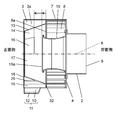
- FIG. 1 is a perspective view of the cyclone separation device according to the first embodiment of the present disclosure as viewed from the diagonally lower front side.
- FIG. 2 is a cross-sectional view of the side surface of the cyclone separator.
- FIG. 3 is a detailed view of the square separator of the cyclone separator (a diagram showing the relationship between the cover and the square separator).
- FIG. 4 is a cross-sectional view of the front of the cyclone separator.
- FIG. 5 is a cross-sectional view of the separation chamber of the cyclone separation device.
- FIG. 6 is a front sectional view of the cyclone separation device according to the second embodiment of the present disclosure.
- FIG. 7 is a diagram showing details of the discharge unit of the cyclone separator.
- the cyclone separation device of the present disclosure includes an inflow port, a swirling flow generating part, an outflow port, and an outlet.
- the inflow port allows air to flow into the housing.
- the swirling airflow generating unit generates a swirling airflow.
- the outlet is provided on the back surface of the housing and allows air to flow out of the housing.
- a separation chamber and a swivel chamber are formed inside the housing.
- the inside of the housing is provided with a space dividing plate that partitions the outer peripheral side close to the side surface of the housing and the inner peripheral side including the central portion of the housing.
- the separation chamber and the swivel chamber are formed by a partition plate.
- the space dividing plate is provided with a through hole for communicating the separation chamber and the swivel chamber.
- the discharge port is an opening that communicates the inside of the separation chamber with the outside of the housing, and is always open.
- an inflow airflow control plate is arranged above the discharge port in the separation chamber.
- the inflow airflow control plate is a plate whose through hole side is inclined downward when viewed from the front side of the housing.
- the separation chamber is an annular space that straddles four quadrants in a coordinate plane centered on the central axis.
- the through hole is located in the second quadrant of the coordinate plane in the direction of airflow swirling in the swirl chamber.
- the separation chamber has a curved surface along the space dividing plate in the third and fourth quadrants of the coordinate plane, and has two planes parallel to the axis of the coordinate plane in the first quadrant and the second quadrant, respectively. ..
- the foreign matter separated in the separation chamber can be discharged from the discharge port to the outside of the housing by the force of the natural wind, and the frequency of maintenance can be reduced.
- the outlet Since the outlet is always open, airflow flows from the outlet toward the separation chamber.
- the inflow airflow control plate can direct the direction of the airflow flowing in from the discharge port to the side opposite to the through hole, it is possible to prevent the foreign matter lowered by the inflowing airflow from directly flowing into the through hole. It is possible to suppress the re-scattering phenomenon. Further, by the action of the inflow airflow control plate, the airflow flowing in from the discharge port can flow in the directions of the fourth quadrant and the first quadrant away from the through hole.
- the cross-sectional area of the separation chamber expands, so that the force of the airflow weakens and it is possible to prevent foreign matter from being lifted to the upper part of the separation chamber. Therefore, the re-scattering phenomenon can be further prevented.
- the two planes parallel to the axis of the coordinate plane constitute the separation chamber side surface which is the side surface of the separation chamber and the separation chamber top surface which is the top surface of the separation chamber.
- the bottom surface of the separation chamber (bottom surface of the separation chamber) is configured to include a curved surface in which the side surface side of the separation chamber is raised, or a surface in which the side surface side of the separation chamber is raised by a continuous surface of the curved surface and the inclined surface.
- the cross section of the portion including the central axis and intersecting with the separation chamber, which is in contact with the side surface of the separation chamber, has an area increased as it approaches the top surface of the separation chamber.
- the bottom surface of the separation chamber has a downward slope toward the discharge port.
- the foreign matter discharged from the through hole into the separation chamber rolls down along the inclination, and the foreign matter tends to collect near the discharge port, so that the foreign matter is discharged.
- the side surface of the separation chamber is erected in the vertical direction, and the area of the cross section that intersects the side surface of the separation chamber in the direction of rotation toward the second quadrant is increased, so that the airflow toward the upper part of the separation chamber is vertical. It faces upward along the surface. Therefore, the foreign matter rides on the air flow and scatters upward in the vertical direction.
- the top surface of the separation chamber is a horizontal plane, the rising airflow easily collides with the top surface of the separation chamber and loses its momentum. Therefore, above the separation chamber on the through hole side, it is possible to prevent the foreign matter from falling directly into the through hole even if it soars up. Above the separation chamber on the side without the through hole, it is possible to prevent foreign matter from traveling to the through hole side through the outside of the space dividing plate. That is, the re-scattering phenomenon can be further prevented.
- the cyclone separation device has a hexahedral housing.
- the housing is provided with a partition plate that separates the front side of the housing from the back side of the housing.
- the four side surfaces adjacent to the back side of the housing are open on the back side of the partition plate.
- the opening is provided with an inflow port for communicating with the swirling flow generating portion.
- a space dividing plate, a bottom surface of the separation chamber, a top surface of the separation chamber, a side surface of the separation chamber, and an outlet are arranged on the front side of the housing.
- the front side portion of the inner wall surface of the housing with the partition plate as a boundary is formed by the top surface of the separation chamber and the side surface of the separation chamber.
- the device can be miniaturized by having each surface of the housing serve as a surface constituting the separation chamber. Can be done. In addition, the separated foreign matter is discharged by the natural wind, and the re-scattering phenomenon can be suppressed.
- FIG. 1 is a perspective view of the cyclone separator according to the first embodiment of the present disclosure as viewed from the diagonally lower front side.
- the ventilation port hood 1 shown in FIG. 1 is attached to the air supply port provided on the outer wall of the house. It is installed on the outer wall of a house and attached to an air supply port that takes in outdoor air into the house.
- the device (not shown) that takes in the outdoor air into the house is equipped with a blower (not shown) and a ventilation duct (not shown) installed in the house.
- the ventilation port hood 1 is connected to the blower by the ventilation duct. As a result, the air that has passed through the ventilation port hood 1 can be introduced into the room.
- the ventilation port hood 1 is connected to the ventilation duct by using the outflow pipe 2 and is installed so as to project from the outer wall of the house.
- the housing 5 of the ventilation port hood 1 has a hexahedral shape composed of a cover 3 on the front side and a base plate 4 on the back side.
- the cover 3, which is the main part of the ventilation port hood 1, is a square box body that closes the front side, and the four side surfaces are opened as the inflow port 7 on the side close to the back side.
- the shape of the front surface of FIG. 1, that is, the front surface of the ventilation port hood 1 is flat, but it may be a dome shape with a protruding central portion.
- the side surface of the cover 3 is adjacent to the base plate 4, and the cover 3 forms a part of the outer shell of the ventilation port hood 1.
- a plurality of fixed blades 8 are provided as swirling flow generating parts for swirling the inflow air, in which the downstream side is arranged close to the central axis 6. That is, the fixed blades 8 are arranged at equal intervals rotationally symmetrically with respect to the central axis 6. Further, a net may be provided on the outer peripheral portion of the inflow port 7 or the fixing blade 8 so that large insects and birds do not invade the device.
- the base plate 4 has a circular opening in the center, and the outflow pipe 2 is connected to the opening.
- the air inside the cover 3 is discharged from the outlet 9 which is one end of the outflow pipe 2.
- the discharge portion 11 is provided with a discharge port 12 having a discharge promoting surface 10 inclined toward the lower portion in a direction in which the cross-sectional area becomes smaller, and an opening at the tip portion thereof so as to communicate the inside and outside of the ventilation port hood 1.
- the discharge unit 11 is provided with a discharge promotion surface 10 having an inclination on the inside and the outside, another two surfaces 10a (see FIG. 5), and a discharge port 12.
- the discharge promotion surface 10 is two surfaces arranged symmetrically with the surfaces facing each other. As shown in FIG. 5, in the discharge unit 11, the discharge promotion surface 10 is connected to another two surfaces 10a, and a discharge port 12 that is always open is formed at the lowermost portion. The discharge portion 11 is located at the bottom of the cover 3.
- the discharge portion 11 is provided with a discharge port 12 having a discharge promoting surface 10 inclined toward the lower portion in a direction in which the cross-sectional area becomes smaller, and an opening at the tip portion thereof so as to communicate the inside and outside of the ventilation port hood 1.
- the discharge port 12 has a rectangular shape.
- the discharge port 12 has a rectangular shape in which the long side of the rectangle is arranged parallel to the central axis 6 at the lower part of the discharge portion 11.
- the discharge port 12 has an elongated shape, it is possible to prevent large insects and birds from invading, and it is possible to secure an area and easily discharge the separated foreign matter. Further, by arranging the long side of the discharge port 12 parallel to the central axis 6, the discharge effect by the natural wind described later can be enhanced.
- the structure in which the emission promoting surfaces 10 are arranged symmetrically can obtain the same emission promoting effect regardless of whether the natural wind blows from the left or right.
- the discharge promoting surface 10 having inclinations on both the left and right sides is required, it does not have to have a strictly symmetrical structure, and the inclination angles may be different on the left and right sides.
- the natural wind that collides with the discharge promoting surface 10 is made to have a smooth surface that gradually steers downward like an inverted Fuji so that the direction can be smoothly changed.
- FIG. 2 is a cross-sectional view of the side surface of the cyclone separator according to the first embodiment.
- the internal space 3a surrounded by the cover 3 and the base plate 4 is spatially divided into a fixing blade 8 and an inner cylinder tube 19.
- a plate 13 and a square separator 32 are provided.
- the inner cylinder tube 19 and the fixing blade 8 are connected to the base plate 4.
- the inner tube 19 and the fixing blade 8 are arranged concentrically with respect to the central axis 6.
- the inner tube 19 is arranged inside the fixing blade 8.
- the inner cylinder pipe 19 is a pipe body communicating with the outflow pipe 2.
- the inner cylinder pipe 19 is provided on the side opposite to the outlet 9 with the base plate 4 interposed therebetween so as to communicate with the outlet 9.
- the end surface 19a of the inner cylinder tube 19 is located on the front side of the cover 3 as compared with the end surface 8a of the fixing blade 8.
- the end face 19a is arranged on the back side with respect to the fixed blade 8 in the direction along the central axis 6.
- the inner diameter of the inner cylinder pipe 19 is smaller than the inner diameter of the outflow pipe 2, but the same size may be used.
- the inner cylinder pipe 19 may be shaped to gradually expand.
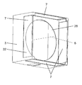
- FIG. 3 is a detailed view of the square separator of the cyclone separator according to the first embodiment (a diagram showing the relationship between the cover and the square separator).
- the square separator 32 is a plate body having an opening 28 in the center, is arranged perpendicular to the central axis 6, and divides the internal space 3a into two.
- the square separator 32 has a fixing blade 8 connected to one surface and a space dividing plate 13 connected to the other surface. That is, in the internal space 3a surrounded by the cover 3 and the base plate 4, the fixing blade 8, the square separator 32, and the space dividing plate 13 are arranged in this order.
- the inflow port 7 is provided on the four side surfaces of the cover 3 so as to face the fixed blade 8. As shown in FIG. 3, the inflow port 7 is arranged on the back side of the cover 3 with the square separator 32 as a boundary.
- the space dividing plate 13 is a tubular body, and the central axis of the tubular body is aligned with the central axis 6 to partition the inside of the cover 3 into the inside and the outside.
- a swivel chamber 14 is formed inside the space dividing plate 13.
- a separation chamber 15 is formed on the outside of the space dividing plate 13. The swivel chamber 14 and the separation chamber 15 communicate with each other through a through hole 16 provided in the space dividing plate 13.
- the swivel chamber 14 has a truncated cone shape with an inclined surface on the side surface. That is, the cross section of the swivel chamber 14 (the direction of the plane perpendicular to the central axis 6) is set so that the area increases toward the base plate 4 side in the cover 3.
- the swivel chamber 14 may have a cylindrical shape with the same cross-sectional area.
- the inside of the space dividing plate 13 is the swivel chamber 14 including the central portion of the cover 3, and the outside of the space dividing plate 13 (the space surrounded by the space dividing plate 13 and the cover 3) is the separation chamber. It is 15.
- FIG. 4 is a cross-sectional view of the front of the cyclone separation device of the first embodiment. It is sectional drawing which cut the front side from the inflow port 7 of a cover 3 at the position which contains the separation chamber 15.
- the space occupied by the separation chamber 15 has four quadrants in the Cartesian coordinate plane 33 shown centering on the central axis 6 and using the X axis 38 in the horizontal direction and the Y axis 39 in the vertical direction. It is a circular space that straddles.
- the airflow swirling direction in the swirl chamber 14 is indicated by a white arrow.
- the through hole 16 is located in the second quadrant 34 of the orthogonal coordinate plane 33 in the airflow swirling direction in the swirl chamber 14.
- the separation chamber 15 has a curved surface 29b along the space dividing plate 13 in the third quadrant 35 and the fourth quadrant 36 of the orthogonal coordinate plane 33.
- the first quadrant 37 and the second quadrant 34 have two planes parallel to the X-axis 38 and the Y-axis 39 forming the coordinate plane 33, respectively.
- the two planes parallel to the X-axis 38 and the Y-axis 39 are the separation chamber side surface 30 and the separation chamber top surface 31 shown in FIG.
- the side surface of the separation chamber 15 is composed of the separation chamber bottom surface 29, the separation chamber side surface 30, and the separation chamber top surface 31, and the inner wall surface of the cover 3 constituting the housing 5 is formed.
- the separation chamber side surface 30 and the separation chamber top surface 31 are provided.
- the side surface 30 of the separation chamber is a flat surface erected in the vertical direction, and is two surfaces located on the target with the discharge port 12 located at the center thereof.
- the upper portion of the separation chamber side surface 30 is adjacent to the separation chamber top surface 31 on a flat surface.
- the lower part of the separation chamber side surface 30 is adjacent to the separation chamber bottom surface 29.
- the bottom surface 29 of the separation chamber is two surfaces located on both sides of the discharge port 12 as a surface connecting the side surface 30 of the separation chamber to the discharge promotion surface 10.
- the bottom surface 29 of the separation chamber is composed of a flat surface 29a, a curved surface 29b, and a flat surface 29c which are continuous surfaces in this order, and the side surface 30 side of the separation chamber is the discharge promoting surface 10.
- the bottom surface 29 of the separation chamber may be composed of only continuous curved surfaces.
- the separation chamber 15 is surrounded by a cover 3, a space dividing plate 13, a square separator 32, a separation chamber bottom surface 29 forming a side surface, a separation chamber side surface 30, and a separation chamber top surface 31. It becomes a space.
- the cross-sectional area of the separation chamber 15 changes around the central axis 6. Since the separation chamber 15 is an annular space, a cross section around the central axis 6 can be defined.
- the cross section of the separation chamber 15 shows a cross section of a portion where one surface including the central axis 6 intersects the space of the separation chamber. Since the separation chamber is an annular space surrounding the central axis 6, there are two portions (both sides of the central axis 6) that intersect with the space of the separation chamber when considering the surface including the central axis 6. One side means to represent one cross section.
- the cross section 41 intersecting the side surface 30 of the separation chamber has the smallest cross-sectional area in the cross section 42 at the horizontal position (on the X axis 38). Further, the cross section 41 is formed by increasing the cross-sectional area on the outside of the space dividing plate 13 and in the rotation direction toward the second quadrant 34. In other words, the cross-sectional area 41 is obtained by increasing the cross-sectional area toward the top surface 31 of the separation chamber within the range of contact with the side surface 30 of the separation chamber.
- the cross section of the portion including the central axis and intersecting with the separation chamber, and the cross section 41 in contact with the side surface of the separation chamber has an area increased as it approaches the top surface 31 of the separation chamber.
- the separation chamber side surface 30 and the separation chamber top surface 31 are directly connected, but they may be connected via a curved surface at the corner portion, or may be connected via a slope. In such a case, it is desirable to gradually increase the cross-sectional area in the Y-axis direction, at least in a range lower than the uppermost bus 40 of the space dividing plate 13.
- the cross section 41 at the same height as the uppermost bus 40 is the cross section 43.
- the cross section of the separation chamber 15 in the second quadrant 34 also faces the separation chamber top surface 31 side in the direction opposite to the airflow swirling direction in the swivel chamber 14 from the X axis 38 within the range of contact with the separation chamber side surface 30. Therefore, the cross-sectional area is gradually increased.
- the cross section 44 intersecting the curved surface 29b has the smallest area.
- the cross section 42 has a larger cross-sectional area than the cross section 44.
- the cross-sectional area of the cross section 41 is set to the third quadrant 35 and the fourth quadrant at least in a range lower than the uppermost bus 40 of the space dividing plate 13 from the entrance of the first quadrant 37 which is the horizontal position. It is larger than the minimum cross-sectional area in quadrant 36.
- the position of the through hole 16 is the side above the central axis 6 in which the swirling direction of the airflow in the swivel chamber 14 faces downward. Further, as shown in the cross-sectional view of FIG. 2, it is the position farthest from the inflow port 7 in the direction parallel to the central axis 6.
- the through hole 16 is provided at a distance from the tip end portion of the inner cylinder tube 19 in the direction of the central axis 6.
- the base of the space dividing plate 13 (the end on the fixed blade 8 side) is connected to the square separator 32.
- the gap between the circular space dividing plate 13 and the square cover 3 is closed, and one end of the separation chamber 15 is covered to form the separation chamber 15 in the cover 3. It is a circular closed space.
- the air that has passed through the inflow port 7 is prevented from directly flowing into the separation chamber 15. If, in the separation chamber 15, there is a gap communicating with the outside of the device other than the discharge port 12, air will enter from there. Then, in the through hole 16, the airflow toward the swirl chamber 14 becomes strong, so that the foreign matter separated in the swirl chamber 14 cannot be moved to the separation chamber 15, and the separation rate is lowered.
- the top of the space dividing plate 13 (the end on the side different from the fixed blade 8 side) is covered on the front side of the cover 3.
- the lid may be configured with a surface that closes the top of the space dividing plate 13, or the space dividing plate 13 may be brought into contact with the inside of the cover 3.
- a swivel chamber front surface 17 is provided as shown in FIG.
- the space dividing plate 13 and the front surface 17 of the swivel chamber are continuous.
- the relationship between the square separator 32 and each component is such that the inflow port 7 is on the back side of the cover 3 with the square separator 32 as a boundary.
- a fixing blade 8, a base plate 4, an outflow pipe 2, and the like are provided, and a space dividing plate 13, a swivel chamber 14, a separation chamber 15, a discharge port 12, and the like are provided on the front side of the cover 3.
- an opening 28 is provided in the center of the square separator 32.
- the inner tube 19 is provided so as to penetrate the central portion of the opening 28. Further, the opening 28 communicates the space inside the swivel chamber 14 and the fixing blade 8.
- the space outside the space dividing plate 13 and surrounded by the cover 3 is the separation chamber 15. Since the front surface 17 of the swivel chamber is substantially in close contact with the cover 3, the separation chamber 15 is an outer peripheral portion of the tubular space, that is, an annular space. It is essential that the space dividing plate 13 has a rotating body shape regardless of the shape of the cover 3.
- the inner surface of the separation chamber 15 on the front side (shown in FIG. 2) of the cover 3 is also the front surface of the separation chamber 18.
- the degree of closeness between the front of the swivel chamber 17 and the front of the separation chamber 18 is designed so that a slight gap is formed between the front of the swivel chamber 17 and the inner surface of the cover 3 on the front side.
- the front surface 18 of the separation chamber and the front surface 17 of the swivel chamber can be formed on substantially the same surface, so that the cyclone separation device of the first embodiment, that is, the ventilation port hood 1 has a thickness in the direction of the central axis 6. It can be minimized.
- the inflow airflow control plate 20 is arranged above the discharge port 12 inside the separation chamber 15. ing.
- the inflow airflow control plate 20 is a plate body in which the through hole 16 side is inclined downward when viewed from the front side of the housing 5.
- the inflow airflow control plate 20 has an inclination straddling the discharge port center vertical line 24 drawn directly above the center of the discharge port 12. Further, as shown in FIG. 2, the inflow airflow control plate 20 is a plate body extruded from the front surface 18 of the separation chamber in the direction along the central axis 6, and the extruded tip is a space division constituting the separation chamber 15. It collides with the plate 13.
- the inflow airflow control plate 20 has two ends.
- the two ends can be distinguished into an upper end 25 and a lower end 26 by the inclination of the inflow airflow control plate 20.
- the side closer to the central axis 6 is arranged on the upper side, the far side is arranged on the lower side, and the upper side is arranged in the circumferential direction in a direction away from the through hole 16 as compared with the lower side.
- the upper end is the upper end 25, and the lower end is the lower end 26.
- a gap 20a is provided between the upper end portion 25 of the inflow airflow control plate 20 and the space dividing plate 13.
- the outdoor air containing foreign matter flows into the ventilation port hood 1 from the inflow port 7 shown in FIG. By passing through the fixed blade 8, it becomes a swirling airflow. Since the inner cylinder 19 is arranged on the front side of the ventilation port hood 1 with respect to the inflow port 7, the swirling airflow swirls in the swirling chamber 14 toward the front side of the ventilation port hood 1. Here, the foreign matter moves to the space dividing plate 13 side by centrifugal force, and moves into the separation chamber 15 when passing near the through hole 16. The air from which the foreign matter has been separated and removed in this way flows into the inner cylinder pipe 19 and flows out of the device from the outflow port 9 through the outflow pipe 2.
- the foreign matter that has moved to the separation chamber 15 is temporarily stored in the separation chamber 15.
- the inside of the separation chamber 15 is affected by the swirling airflow inside the swirl chamber 14, and the air flows as a swirling airflow in the same direction as the inside of the swirl chamber 14 as a whole (all). Airflow is not always in the same direction). Therefore, the foreign matter stored in the separation chamber 15 also moves under the influence of the swirling airflow.
- the flat surface 29a, the curved surface 29b, and the flat surface 29c form a continuous surface from above.
- the curved surface 29b is a curved surface that is concentric with the space dividing plate 13, but in the plane 29a of the third quadrant and the fourth quadrant, the space in the lower half (third quadrant and fourth quadrant) of the separation chamber 15 moves foreign matter. It is a trumpet-shaped surface with the side in contact with the side surface 30 of the separation chamber widened so as to be easy to make. Further, the flat surface 29c is maintained at an inclination so that foreign matter can easily slide down from the curved surface 29b side to the discharge portion 11 side.
- the discharge unit 11 in the direction along the central axis 6, when the swirling airflow flowing in the separation chamber 15 crosses the discharge part 11, only the foreign matter is discharged to the discharge part 11 without disturbing the swirl airflow. It makes it easier to flow in.
- the direction along the central axis 6 and the thickness direction of the separation chamber are the same.
- the length in the direction along the central axis 6 may be extended to the same length as the thickness of the separation chamber 15.
- a natural wind may blow in the vicinity of the discharge portion 11 on the outside of the housing 5.
- the natural wind changes its direction along the inclination of the discharge promoting surface 10 and becomes a downward airflow.
- Foreign matter existing in the vicinity of the discharge port 12 in the housing 5 is attracted by this air flow and is pulled out of the housing 5. That is, the foreign matter is temporarily stored in the separation chamber 15 and is discharged to the outside of the housing 5 every time a natural wind blows. As a result, the work of discharging the foreign matter separated in the ventilation port hood 1 becomes unnecessary.
- the air flowing from the discharge port 12 into the separation chamber 15 flows in the direction of the discharge port center vertical line 24.
- the airflow flowing in from such an discharge port 12 winds up the foreign matter temporarily stored in the separation chamber 15, passes through the through hole 16, and scatters the foreign matter from the outflow port 9 into the house on the downstream side (re-). Scattering phenomenon) may occur. As shown in FIG. 4, the re-scattering phenomenon can be prevented by providing the inflow airflow control plate 20.
- the inflow airflow control plate 20 has an inclination that covers the upper part of the discharge port 12.
- the airflow flowing in from the discharge port 12 can be made to collide with the inflow airflow control plate 20, and the airflow can be directed away from the through hole 16 by the action of inclination.
- the foreign matter soaring at this time can be directed to the right side of the discharge port center vertical line 24 shown in FIG.
- the cross section 41 of the first quadrant 37 is the third quadrant 35 in the range lower than the uppermost bus 40 from the horizontal position. It is made larger than the minimum cross-sectional area in the fourth quadrant 36, and the cross-sectional area on the side closer to the uppermost bus 40 is gradually increased. As a result, the wind speed of the airflow flowing from the discharge port 12 into the separation chamber 15 can be reduced. By this action, it is possible to weaken the force of the foreign matter separated into the separation chamber 15 soaring upward, suppress the foreign matter from going beyond the uppermost bus 40 toward the through hole 16, and prevent the re-scattering phenomenon. can do.
- the airflow passing through the cross section 42 goes straight up. ..
- the flat top surface 31 of the separation chamber is located in the horizontal direction at the destination of the air flow.
- the cross-sectional area 41 may be expanded even at a position exceeding the uppermost bus 40. There is no problem because the space of the separation chamber 15 continues to expand over a longer distance and the re-scattering phenomenon can be further suppressed.
- the cross section of the separation chamber 15 becomes wider within the range of contact with the separation chamber top surface 31, and the separation chamber top surface 31 is in the horizontal direction.
- the airflow flowing in the separation chamber 15 located in the second quadrant also has horizontal directivity. Therefore, even if the foreign matter exceeds the uppermost bus 40, it continues to scatter in the horizontal direction. Therefore, the inflow of foreign matter into the through hole 16 can be suppressed, and as a result, the re-scattering phenomenon can be prevented.
- the ventilation port hood 1 is installed on the wall surface of the house.
- the wall surface of the house is on the back side.
- the natural wind blowing on the outside of the housing 5 no flow from the back side to the front side is generated. Further, the natural wind flow from the front side to the back side collides with the inflow airflow control plate 20 in the separation chamber 15, and the re-scattering phenomenon can be prevented.
- the foreign matter in the separation chamber 15 can be discharged by the force of the natural wind from the discharge port 12 which is always open, and the work of discharging the separated foreign matter can be eliminated.
- the cross section of the inflow airflow control plate 20 and the separation chamber 15 to expand in the swirling direction of the airflow, the momentum of the airflow flowing in from the discharge port 12 is suppressed and the re-scattering phenomenon is prevented. Can be done. That is, it is possible to provide the ventilation port hood 1 in which the deterioration of the separation performance is suppressed.
- the cross-sectional shape of the second quadrant 34 of the separation chamber 15 is not described in detail, but the cross-sectional shape of the first quadrant 37 is formed with respect to the Y-axis 39. Just do it. It is desirable that the through hole 16 is arranged closer to the X-axis 38 side in the second quadrant 34 from the viewpoint of facilitating the foreign matter discharged from the swivel chamber 14 to the separation chamber 15 to fall downward.
- FIG. 6 is a cross-sectional view of the cover 3 at a position including the separation chamber 15 with the front side cut out from the inflow port 7.
- FIG. 7 is a diagram showing a main part including the emission promoting surface 10.
- the separation chamber 15 is provided with four members: an inflow airflow control plate 20, a return plate 21, a lower shield plate 22, and an upper shield plate 23.
- the lower shielding plate 22, the return plate 21, the inflow airflow control plate 20, and the upper shielding plate 23 are arranged in this order in the direction in which the swirling airflow flows, starting from the through hole 16. There is.
- FIG. 6 shows the discharge port center perpendicular line 24 drawn directly above the center of the discharge port 12.
- the inflow airflow control plate 20 has an inclination that straddles the central vertical line 24 of the discharge port, and is further extruded from the front surface 18 of the separation chamber toward the bottom surface 29 side of the separation chamber until it collides with the surface of the space division plate 13. ..
- the inflow airflow control plate 20 has the same configuration requirements as those in the first embodiment. As already explained, it has two ends. The two ends can be distinguished into an upper end 25 and a lower end 26 by the inclination of the inflow airflow control plate 20.
- the side closer to the central axis 6 is arranged on the upper side, the far side is arranged on the lower side, and the upper side in the circumferential direction is arranged at a position farther from the through hole 16 than the lower side.
- the upper end is the upper end 25, and the lower end is the lower end 26. Further, a gap is provided between the upper end portion 25 of the inflow airflow control plate 20 and the space dividing plate 13.
- the return plate 21 is a plate having a tip protruding from the surface of the discharge promoting surface 10 on the side close to the through hole 16 (may be on the surface of the flat surface 29c on the side close to the through hole 16) toward the discharge port center vertical line 24.
- the protruding tip of the return plate 21 is referred to as the tip end 27.
- the lower shielding plate 22 is a plate body extended so as to overlap a part of the radius drawn from the central axis 6.
- the lower shielding plate 22 is configured so that it is in contact with the space dividing plate 13 on the inner peripheral side and a gap is formed between the lower shielding plate 22 and the flat surface 29c on the outer peripheral side.
- the arrangement of the discharge promoting surface 10, the tip end portion 27 of the return plate 21, and the lower shielding plate 22 has the following relationship. That is, it is necessary to configure the lower shielding plate 22 to exist on the reverse extension line of the tangent line (dotted line 21a in FIG. 7) drawn from the tip end portion 27 to the discharge promoting surface 10.
- the upper shielding plate 23 is located directly above the central axis 6 in a state where the discharge portion 11 is located at the lowermost portion of the cover 3.
- the inner peripheral side of the upper shielding plate 23 is brought into contact with the space dividing plate 13, and a gap 23a is formed on the outer peripheral side.
- the position of the upper shielding plate 23 may be anywhere as long as it is above the separation chamber 15 and above the through hole 16 (in the upper space).
- the outdoor air containing foreign matter flows into the ventilation port hood 1 from the inflow port 7 shown in FIG. 1, and becomes a swirling air flow by the fixed blade 8.
- the swirling airflow swirls in the swirling chamber 14 toward the front side of the ventilation port hood 1.
- a centrifugal force acts on the foreign matter, and the foreign matter moves to the space dividing plate 13 side and moves into the separation chamber 15 when passing near the through hole 16.
- the air from which the foreign matter has been removed flows into the inner cylinder pipe 19, passes through the outflow pipe 2, and flows out of the device from the outflow port 9.
- the foreign matter that has moved to the separation chamber 15 is temporarily stored in the separation chamber 15. Since the pressure inside the ventilation port hood 1 is negative due to the blower, air also flows into the separation chamber 15 from the discharge port 12. The inflowing air passes through the through hole 16 shown in FIG. 2, flows into the swirling chamber 14, and merges with the swirling airflow in the swirling chamber 14.
- the airflow flowing in from the discharge port 12 winds up the foreign matter temporarily stored in the separation chamber 15, passes through the through hole 16, and scatters the foreign matter from the outflow port 9 into the house on the downstream side (re-scattering phenomenon). is there.
- this re-scattering phenomenon can be prevented.
- the inflow airflow control plate 20 so as to cover the upper part of the discharge port 12, the airflow flowing in from the discharge port 12 can collide with the inflow airflow control plate 20, so that the airflow is directed away from the through hole 16. It can be changed.
- the foreign matter soars up on the side where the through hole 16 does not exist on the right side of the discharge port center vertical line 24 in FIG. 4, so that the re-inflow of the foreign matter into the through hole 16 can be reduced and the re-scattering phenomenon can be prevented. That is, by providing the inflow airflow control plate 20, it is possible to suppress a decrease in separation performance.
- the foreign matter that has risend on the side where the through hole 16 does not exist may go further upward through the annular separation chamber 15 and head toward the through hole 16. Further, by providing the upper shielding plate 23, the momentum of the swirling airflow (indicated by the white arrow in FIG. 3) in the separation chamber 15 can be weakened, so that the re-scattering phenomenon can be suppressed.
- the gap 20a is further provided on the upper end 25 side of the inflow airflow control plate 20, a part of the airflow that collides with the lower shielding plate 22 is passed through, and the side where the through hole 16 does not exist. Can be escaped to. That is, the airflow from the lower shielding plate 22 toward the through hole 16 side can be further reduced, and the re-scattering phenomenon can be further suppressed.
- the direction of the natural wind is controlled by controlling the airflow flowing in from the discharge port 12 by the four constituent requirements of the inflow airflow control plate 20, the return plate 21, the lower shielding plate 22, and the upper shielding plate 23. Regardless, the re-scattering phenomenon can be suppressed. That is, it is possible to provide the ventilation port hood 1 capable of discharging the foreign matter in the separation chamber 15 by the force of the natural wind from the discharge port 12 which is always open. In particular, it is possible to provide a ventilation port hood 1 capable of reducing the frequency of maintenance and suppressing deterioration of separation performance.
- the separation performance of the ventilation port hood 1, that is, the cyclone separator is improved by adding the three configurations of the return plate 21, the lower shield plate 22, and the upper shield plate 23 to the configuration of the first embodiment. Can be improved.
- the cyclone separation device can prevent the re-scattering phenomenon and suppress the deterioration of the separation performance while enabling the automatic discharge of the separated foreign matter by using the natural wind. As a result, it is useful as a ventilation port hood or the like that takes in outdoor air to ventilate the inside of the house.
- Ventilation port hood Outflow pipe 3 Cover 4 Base plate 5 Housing 6 Central axis 7 Inflow port 8 Fixed blade 9 Outflow outlet 10 Discharge promotion surface 11 Discharge part 12 Discharge port 13 Space division plate 14 Swing chamber 15 Separation chamber 16 Through hole 17 Front of swivel chamber 18 Front of separation chamber 19 Inner cylinder pipes 8a, 19a End surface 20 Inflow airflow control plate 20a Gap 21 Return plate 21a Dotted line 22 Lower shielding plate 23 Upper shielding plate 23a Gap 24 Outlet center vertical line 25 Upper end 26 Lower side End 27 Tip end 28 Opening 29 Separation chamber bottom surface 29a Plane 29b Curved surface 29c Plane 30 Separation chamber side surface 31 Separation chamber top surface 32 Square separator 33 Coordinate plane 35 Third quadrant 34 Second quadrant 36 Fourth quadrant 37 First quadrant 38 X-axis 39 Y-axis 40 Top bus 41 Cross section 42 Cross section 43 Cross section 44 Cross section 40
Landscapes
- Engineering & Computer Science (AREA)
- Chemical & Material Sciences (AREA)
- Combustion & Propulsion (AREA)
- Mechanical Engineering (AREA)
- General Engineering & Computer Science (AREA)
- Physics & Mathematics (AREA)
- Geometry (AREA)
- Chemical Kinetics & Catalysis (AREA)
- Fluid Mechanics (AREA)
- Cyclones (AREA)
- Separating Particles In Gases By Inertia (AREA)
- Ventilation (AREA)
Applications Claiming Priority (2)
| Application Number | Priority Date | Filing Date | Title |
|---|---|---|---|
| JP2019-079462 | 2019-04-18 | ||
| JP2019079462A JP7349597B2 (ja) | 2019-04-18 | 2019-04-18 | サイクロン分離装置 |
Publications (1)
| Publication Number | Publication Date |
|---|---|
| WO2020213242A1 true WO2020213242A1 (ja) | 2020-10-22 |
Family
ID=72838124
Family Applications (1)
| Application Number | Title | Priority Date | Filing Date |
|---|---|---|---|
| PCT/JP2020/005164 Ceased WO2020213242A1 (ja) | 2019-04-18 | 2020-02-10 | サイクロン分離装置 |
Country Status (2)
| Country | Link |
|---|---|
| JP (1) | JP7349597B2 (https=) |
| WO (1) | WO2020213242A1 (https=) |
Families Citing this family (1)
| Publication number | Priority date | Publication date | Assignee | Title |
|---|---|---|---|---|
| CN121101391B (zh) * | 2025-11-14 | 2026-03-27 | 杭州巨星科技股份有限公司 | 吸尘器 |
Citations (5)
| Publication number | Priority date | Publication date | Assignee | Title |
|---|---|---|---|---|
| JP2004121622A (ja) * | 2002-10-04 | 2004-04-22 | Toshiba Tec Corp | 電気掃除機 |
| JP2008036579A (ja) * | 2006-08-09 | 2008-02-21 | Air Water Emoto Kk | サイクロン分離装置およびそれを用いた住宅換気用給気フード |
| JP2012511684A (ja) * | 2008-12-10 | 2012-05-24 | エレクトロラクス ホーム プロダクツ コーポレーション エヌ ヴィ | 吸入フード |
| JP2014198328A (ja) * | 2013-03-13 | 2014-10-23 | パナソニック株式会社 | 集塵装置およびこれを用いた空気浄化装置 |
| JP2018034146A (ja) * | 2016-08-30 | 2018-03-08 | パナソニックIpマネジメント株式会社 | サイクロン分離装置 |
Family Cites Families (2)
| Publication number | Priority date | Publication date | Assignee | Title |
|---|---|---|---|---|
| JPS6115017U (ja) * | 1984-07-03 | 1986-01-28 | 東京濾器株式会社 | プリクリ−ナ |
| JP6814933B2 (ja) | 2017-02-06 | 2021-01-20 | パナソニックIpマネジメント株式会社 | 換気口フード |
-
2019
- 2019-04-18 JP JP2019079462A patent/JP7349597B2/ja active Active
-
2020
- 2020-02-10 WO PCT/JP2020/005164 patent/WO2020213242A1/ja not_active Ceased
Patent Citations (5)
| Publication number | Priority date | Publication date | Assignee | Title |
|---|---|---|---|---|
| JP2004121622A (ja) * | 2002-10-04 | 2004-04-22 | Toshiba Tec Corp | 電気掃除機 |
| JP2008036579A (ja) * | 2006-08-09 | 2008-02-21 | Air Water Emoto Kk | サイクロン分離装置およびそれを用いた住宅換気用給気フード |
| JP2012511684A (ja) * | 2008-12-10 | 2012-05-24 | エレクトロラクス ホーム プロダクツ コーポレーション エヌ ヴィ | 吸入フード |
| JP2014198328A (ja) * | 2013-03-13 | 2014-10-23 | パナソニック株式会社 | 集塵装置およびこれを用いた空気浄化装置 |
| JP2018034146A (ja) * | 2016-08-30 | 2018-03-08 | パナソニックIpマネジメント株式会社 | サイクロン分離装置 |
Also Published As
| Publication number | Publication date |
|---|---|
| JP2020175334A (ja) | 2020-10-29 |
| JP7349597B2 (ja) | 2023-09-25 |
Similar Documents
| Publication | Publication Date | Title |
|---|---|---|
| JP6906150B2 (ja) | サイクロン分離装置 | |
| KR102323777B1 (ko) | 송풍장치 및 이를 포함하는 공기조화기의 실외기 | |
| JP7554966B2 (ja) | サイクロン分離装置 | |
| CN110905858B (zh) | 一种吸油烟机 | |
| JP2019098318A5 (https=) | ||
| JP6387535B2 (ja) | サイクロン分離装置 | |
| CN109641222B (zh) | 旋风式分离装置 | |
| JPWO2015001663A1 (ja) | 送風機及び室外機 | |
| JP2008002379A (ja) | 遠心ファン | |
| WO2020213242A1 (ja) | サイクロン分離装置 | |
| WO2019111773A1 (ja) | サイクロン分離装置 | |
| JP6814933B2 (ja) | 換気口フード | |
| WO2021208497A1 (zh) | 机头组件、风道系统、风扇 | |
| JP7414533B2 (ja) | 送風装置 | |
| JP2018128145A5 (https=) | ||
| JP2024063284A (ja) | サイクロン分離装置 | |
| CN221705684U (zh) | 加湿器 | |
| JP2019157683A (ja) | 送風装置 | |
| WO2018143326A1 (ja) | 換気口フード | |
| CN213542809U (zh) | 低噪音大风量出风口箱 | |
| JPH08285340A (ja) | 人工竜巻式局所排気装置 | |
| JP2020175334A5 (https=) | ||
| JP6906135B2 (ja) | サイクロン分離装置 | |
| JPH05296511A (ja) | 竜巻を利用した換気装置 | |
| JP2021164924A (ja) | サイクロン分離装置 |
Legal Events
| Date | Code | Title | Description |
|---|---|---|---|
| 121 | Ep: the epo has been informed by wipo that ep was designated in this application |
Ref document number: 20791921 Country of ref document: EP Kind code of ref document: A1 |
|
| NENP | Non-entry into the national phase |
Ref country code: DE |
|
| 122 | Ep: pct application non-entry in european phase |
Ref document number: 20791921 Country of ref document: EP Kind code of ref document: A1 |