WO2020213242A1 - サイクロン分離装置 - Google Patents
サイクロン分離装置 Download PDFInfo
- Publication number
- WO2020213242A1 WO2020213242A1 PCT/JP2020/005164 JP2020005164W WO2020213242A1 WO 2020213242 A1 WO2020213242 A1 WO 2020213242A1 JP 2020005164 W JP2020005164 W JP 2020005164W WO 2020213242 A1 WO2020213242 A1 WO 2020213242A1
- Authority
- WO
- WIPO (PCT)
- Prior art keywords
- separation chamber
- housing
- chamber
- quadrant
- discharge port
- Prior art date
Links
Images


Classifications
-
- F—MECHANICAL ENGINEERING; LIGHTING; HEATING; WEAPONS; BLASTING
- F24—HEATING; RANGES; VENTILATING
- F24F—AIR-CONDITIONING; AIR-HUMIDIFICATION; VENTILATION; USE OF AIR CURRENTS FOR SCREENING
- F24F7/00—Ventilation
- F24F7/003—Ventilation in combination with air cleaning
-
- B—PERFORMING OPERATIONS; TRANSPORTING
- B01—PHYSICAL OR CHEMICAL PROCESSES OR APPARATUS IN GENERAL
- B01D—SEPARATION
- B01D45/00—Separating dispersed particles from gases or vapours by gravity, inertia, or centrifugal forces
- B01D45/12—Separating dispersed particles from gases or vapours by gravity, inertia, or centrifugal forces by centrifugal forces
-
- B—PERFORMING OPERATIONS; TRANSPORTING
- B04—CENTRIFUGAL APPARATUS OR MACHINES FOR CARRYING-OUT PHYSICAL OR CHEMICAL PROCESSES
- B04C—APPARATUS USING FREE VORTEX FLOW, e.g. CYCLONES
- B04C5/00—Apparatus in which the axial direction of the vortex is reversed
- B04C5/02—Construction of inlets by which the vortex flow is generated, e.g. tangential admission, the fluid flow being forced to follow a downward path by spirally wound bulkheads, or with slightly downwardly-directed tangential admission
- B04C5/04—Tangential inlets
-
- B—PERFORMING OPERATIONS; TRANSPORTING
- B04—CENTRIFUGAL APPARATUS OR MACHINES FOR CARRYING-OUT PHYSICAL OR CHEMICAL PROCESSES
- B04C—APPARATUS USING FREE VORTEX FLOW, e.g. CYCLONES
- B04C5/00—Apparatus in which the axial direction of the vortex is reversed
- B04C5/08—Vortex chamber constructions
- B04C5/081—Shapes or dimensions
-
- F—MECHANICAL ENGINEERING; LIGHTING; HEATING; WEAPONS; BLASTING
- F24—HEATING; RANGES; VENTILATING
- F24F—AIR-CONDITIONING; AIR-HUMIDIFICATION; VENTILATION; USE OF AIR CURRENTS FOR SCREENING
- F24F7/00—Ventilation
- F24F7/04—Ventilation with ducting systems, e.g. by double walls; with natural circulation
Definitions
- the present disclosure relates to a cyclone separation device that separates foreign substances contained in air by using centrifugal force.
- this type of cyclone separator is attached to the air supply port of the outer wall of the house in order to separate insects and dust (hereinafter referred to as foreign substances) that are sucked in together with the outside air when the outside air is taken into the room. I am using it.
- a cyclone separation device is provided at an air supply port portion that takes in outdoor air (for example, Patent Document 1). According to this, it is possible to prevent foreign matter contained in the air from entering the ventilation device. This is because the foreign matter contained in the air is separated by the cyclone separation device and stored in the separation chamber provided inside the cyclone separation device.
- the separation chamber of a similar cyclone separator has a structure that opens the lid using wind power, and when the lid is opened by the wind generated in the natural world (hereinafter, natural wind), the separated foreign matter is outdoors.
- natural wind the wind generated in the natural world
- Patent Document 2 Japanese Patent Document 2
- the configuration is provided with a wind receiving plate that moves like a pendulum under the force of wind pressure.
- the wind receiving plate has a fulcrum at the top, and the wind receiving plate that receives the force of the wind moves like a pendulum, so that the two lids provided in the separation chamber open alternately. ..
- the present disclosure is a cyclone separation device capable of suppressing deterioration of separation performance due to re-scattering while having a discharge structure capable of discharging foreign substances separated by a cyclone by natural wind without requiring regular maintenance.
- the purpose is to provide.
- the cyclone separation device includes an inlet, a swirling flow generator, an outlet, and an outlet.
- the inflow port allows air to flow into the housing.
- the swirling airflow generating unit generates a swirling airflow.
- the outlet is provided on the back surface of the housing and allows air to flow out of the housing.
- a separation chamber and a swivel chamber are formed inside the housing.
- the inside of the housing is provided with a space dividing plate that partitions the outer peripheral side close to the side surface of the housing and the inner peripheral side including the central portion of the housing.
- the separation chamber and the swivel chamber are formed by a partition plate.
- the space dividing plate is provided with a through hole for communicating the separation chamber and the swivel chamber.
- the discharge port is an opening that communicates the inside of the separation chamber with the outside of the housing, and is always open.
- an inflow airflow control plate is arranged above the discharge port in the separation chamber.
- the inflow airflow control plate is a plate whose through hole side is inclined downward when viewed from the front side of the housing.
- the separation chamber is an annular space that straddles four quadrants in a coordinate plane centered on the central axis.
- the through hole is located in the second quadrant of the coordinate plane in the direction of airflow swirling in the swirl chamber.
- the separation chamber has a curved surface along the space dividing plate in the third and fourth quadrants of the coordinate plane, and has two planes parallel to the axis of the coordinate plane in the first quadrant and the second quadrant, respectively. ..
- the foreign matter separated in the separation chamber can be discharged from the discharge port to the outside of the housing by the force of the natural wind, and the frequency of maintenance can be reduced.
- the constantly open discharge port makes it possible to discharge the separated foreign matter to the outside of the housing by the force of the natural wind, while suppressing the occurrence of the re-scattering phenomenon.
- FIG. 1 is a perspective view of the cyclone separation device according to the first embodiment of the present disclosure as viewed from the diagonally lower front side.
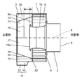
- FIG. 2 is a cross-sectional view of the side surface of the cyclone separator.
- FIG. 3 is a detailed view of the square separator of the cyclone separator (a diagram showing the relationship between the cover and the square separator).
- FIG. 4 is a cross-sectional view of the front of the cyclone separator.
- FIG. 5 is a cross-sectional view of the separation chamber of the cyclone separation device.
- FIG. 6 is a front sectional view of the cyclone separation device according to the second embodiment of the present disclosure.
- FIG. 7 is a diagram showing details of the discharge unit of the cyclone separator.
- the cyclone separation device of the present disclosure includes an inflow port, a swirling flow generating part, an outflow port, and an outlet.
- the inflow port allows air to flow into the housing.
- the swirling airflow generating unit generates a swirling airflow.
- the outlet is provided on the back surface of the housing and allows air to flow out of the housing.
- a separation chamber and a swivel chamber are formed inside the housing.
- the inside of the housing is provided with a space dividing plate that partitions the outer peripheral side close to the side surface of the housing and the inner peripheral side including the central portion of the housing.
- the separation chamber and the swivel chamber are formed by a partition plate.
- the space dividing plate is provided with a through hole for communicating the separation chamber and the swivel chamber.
- the discharge port is an opening that communicates the inside of the separation chamber with the outside of the housing, and is always open.
- an inflow airflow control plate is arranged above the discharge port in the separation chamber.
- the inflow airflow control plate is a plate whose through hole side is inclined downward when viewed from the front side of the housing.
- the separation chamber is an annular space that straddles four quadrants in a coordinate plane centered on the central axis.
- the through hole is located in the second quadrant of the coordinate plane in the direction of airflow swirling in the swirl chamber.
- the separation chamber has a curved surface along the space dividing plate in the third and fourth quadrants of the coordinate plane, and has two planes parallel to the axis of the coordinate plane in the first quadrant and the second quadrant, respectively. ..
- the foreign matter separated in the separation chamber can be discharged from the discharge port to the outside of the housing by the force of the natural wind, and the frequency of maintenance can be reduced.
- the outlet Since the outlet is always open, airflow flows from the outlet toward the separation chamber.
- the inflow airflow control plate can direct the direction of the airflow flowing in from the discharge port to the side opposite to the through hole, it is possible to prevent the foreign matter lowered by the inflowing airflow from directly flowing into the through hole. It is possible to suppress the re-scattering phenomenon. Further, by the action of the inflow airflow control plate, the airflow flowing in from the discharge port can flow in the directions of the fourth quadrant and the first quadrant away from the through hole.
- the cross-sectional area of the separation chamber expands, so that the force of the airflow weakens and it is possible to prevent foreign matter from being lifted to the upper part of the separation chamber. Therefore, the re-scattering phenomenon can be further prevented.
- the two planes parallel to the axis of the coordinate plane constitute the separation chamber side surface which is the side surface of the separation chamber and the separation chamber top surface which is the top surface of the separation chamber.
- the bottom surface of the separation chamber (bottom surface of the separation chamber) is configured to include a curved surface in which the side surface side of the separation chamber is raised, or a surface in which the side surface side of the separation chamber is raised by a continuous surface of the curved surface and the inclined surface.
- the cross section of the portion including the central axis and intersecting with the separation chamber, which is in contact with the side surface of the separation chamber, has an area increased as it approaches the top surface of the separation chamber.
- the bottom surface of the separation chamber has a downward slope toward the discharge port.
- the foreign matter discharged from the through hole into the separation chamber rolls down along the inclination, and the foreign matter tends to collect near the discharge port, so that the foreign matter is discharged.
- the side surface of the separation chamber is erected in the vertical direction, and the area of the cross section that intersects the side surface of the separation chamber in the direction of rotation toward the second quadrant is increased, so that the airflow toward the upper part of the separation chamber is vertical. It faces upward along the surface. Therefore, the foreign matter rides on the air flow and scatters upward in the vertical direction.
- the top surface of the separation chamber is a horizontal plane, the rising airflow easily collides with the top surface of the separation chamber and loses its momentum. Therefore, above the separation chamber on the through hole side, it is possible to prevent the foreign matter from falling directly into the through hole even if it soars up. Above the separation chamber on the side without the through hole, it is possible to prevent foreign matter from traveling to the through hole side through the outside of the space dividing plate. That is, the re-scattering phenomenon can be further prevented.
- the cyclone separation device has a hexahedral housing.
- the housing is provided with a partition plate that separates the front side of the housing from the back side of the housing.
- the four side surfaces adjacent to the back side of the housing are open on the back side of the partition plate.
- the opening is provided with an inflow port for communicating with the swirling flow generating portion.
- a space dividing plate, a bottom surface of the separation chamber, a top surface of the separation chamber, a side surface of the separation chamber, and an outlet are arranged on the front side of the housing.
- the front side portion of the inner wall surface of the housing with the partition plate as a boundary is formed by the top surface of the separation chamber and the side surface of the separation chamber.
- the device can be miniaturized by having each surface of the housing serve as a surface constituting the separation chamber. Can be done. In addition, the separated foreign matter is discharged by the natural wind, and the re-scattering phenomenon can be suppressed.
- FIG. 1 is a perspective view of the cyclone separator according to the first embodiment of the present disclosure as viewed from the diagonally lower front side.
- the ventilation port hood 1 shown in FIG. 1 is attached to the air supply port provided on the outer wall of the house. It is installed on the outer wall of a house and attached to an air supply port that takes in outdoor air into the house.
- the device (not shown) that takes in the outdoor air into the house is equipped with a blower (not shown) and a ventilation duct (not shown) installed in the house.
- the ventilation port hood 1 is connected to the blower by the ventilation duct. As a result, the air that has passed through the ventilation port hood 1 can be introduced into the room.
- the ventilation port hood 1 is connected to the ventilation duct by using the outflow pipe 2 and is installed so as to project from the outer wall of the house.
- the housing 5 of the ventilation port hood 1 has a hexahedral shape composed of a cover 3 on the front side and a base plate 4 on the back side.
- the cover 3, which is the main part of the ventilation port hood 1, is a square box body that closes the front side, and the four side surfaces are opened as the inflow port 7 on the side close to the back side.
- the shape of the front surface of FIG. 1, that is, the front surface of the ventilation port hood 1 is flat, but it may be a dome shape with a protruding central portion.
- the side surface of the cover 3 is adjacent to the base plate 4, and the cover 3 forms a part of the outer shell of the ventilation port hood 1.
- a plurality of fixed blades 8 are provided as swirling flow generating parts for swirling the inflow air, in which the downstream side is arranged close to the central axis 6. That is, the fixed blades 8 are arranged at equal intervals rotationally symmetrically with respect to the central axis 6. Further, a net may be provided on the outer peripheral portion of the inflow port 7 or the fixing blade 8 so that large insects and birds do not invade the device.
- the base plate 4 has a circular opening in the center, and the outflow pipe 2 is connected to the opening.
- the air inside the cover 3 is discharged from the outlet 9 which is one end of the outflow pipe 2.
- the discharge portion 11 is provided with a discharge port 12 having a discharge promoting surface 10 inclined toward the lower portion in a direction in which the cross-sectional area becomes smaller, and an opening at the tip portion thereof so as to communicate the inside and outside of the ventilation port hood 1.
- the discharge unit 11 is provided with a discharge promotion surface 10 having an inclination on the inside and the outside, another two surfaces 10a (see FIG. 5), and a discharge port 12.
- the discharge promotion surface 10 is two surfaces arranged symmetrically with the surfaces facing each other. As shown in FIG. 5, in the discharge unit 11, the discharge promotion surface 10 is connected to another two surfaces 10a, and a discharge port 12 that is always open is formed at the lowermost portion. The discharge portion 11 is located at the bottom of the cover 3.
- the discharge portion 11 is provided with a discharge port 12 having a discharge promoting surface 10 inclined toward the lower portion in a direction in which the cross-sectional area becomes smaller, and an opening at the tip portion thereof so as to communicate the inside and outside of the ventilation port hood 1.
- the discharge port 12 has a rectangular shape.
- the discharge port 12 has a rectangular shape in which the long side of the rectangle is arranged parallel to the central axis 6 at the lower part of the discharge portion 11.
- the discharge port 12 has an elongated shape, it is possible to prevent large insects and birds from invading, and it is possible to secure an area and easily discharge the separated foreign matter. Further, by arranging the long side of the discharge port 12 parallel to the central axis 6, the discharge effect by the natural wind described later can be enhanced.
- the structure in which the emission promoting surfaces 10 are arranged symmetrically can obtain the same emission promoting effect regardless of whether the natural wind blows from the left or right.
- the discharge promoting surface 10 having inclinations on both the left and right sides is required, it does not have to have a strictly symmetrical structure, and the inclination angles may be different on the left and right sides.
- the natural wind that collides with the discharge promoting surface 10 is made to have a smooth surface that gradually steers downward like an inverted Fuji so that the direction can be smoothly changed.
- FIG. 2 is a cross-sectional view of the side surface of the cyclone separator according to the first embodiment.
- the internal space 3a surrounded by the cover 3 and the base plate 4 is spatially divided into a fixing blade 8 and an inner cylinder tube 19.
- a plate 13 and a square separator 32 are provided.
- the inner cylinder tube 19 and the fixing blade 8 are connected to the base plate 4.
- the inner tube 19 and the fixing blade 8 are arranged concentrically with respect to the central axis 6.
- the inner tube 19 is arranged inside the fixing blade 8.
- the inner cylinder pipe 19 is a pipe body communicating with the outflow pipe 2.
- the inner cylinder pipe 19 is provided on the side opposite to the outlet 9 with the base plate 4 interposed therebetween so as to communicate with the outlet 9.
- the end surface 19a of the inner cylinder tube 19 is located on the front side of the cover 3 as compared with the end surface 8a of the fixing blade 8.
- the end face 19a is arranged on the back side with respect to the fixed blade 8 in the direction along the central axis 6.
- the inner diameter of the inner cylinder pipe 19 is smaller than the inner diameter of the outflow pipe 2, but the same size may be used.
- the inner cylinder pipe 19 may be shaped to gradually expand.
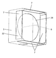
- FIG. 3 is a detailed view of the square separator of the cyclone separator according to the first embodiment (a diagram showing the relationship between the cover and the square separator).
- the square separator 32 is a plate body having an opening 28 in the center, is arranged perpendicular to the central axis 6, and divides the internal space 3a into two.
- the square separator 32 has a fixing blade 8 connected to one surface and a space dividing plate 13 connected to the other surface. That is, in the internal space 3a surrounded by the cover 3 and the base plate 4, the fixing blade 8, the square separator 32, and the space dividing plate 13 are arranged in this order.
- the inflow port 7 is provided on the four side surfaces of the cover 3 so as to face the fixed blade 8. As shown in FIG. 3, the inflow port 7 is arranged on the back side of the cover 3 with the square separator 32 as a boundary.
- the space dividing plate 13 is a tubular body, and the central axis of the tubular body is aligned with the central axis 6 to partition the inside of the cover 3 into the inside and the outside.
- a swivel chamber 14 is formed inside the space dividing plate 13.
- a separation chamber 15 is formed on the outside of the space dividing plate 13. The swivel chamber 14 and the separation chamber 15 communicate with each other through a through hole 16 provided in the space dividing plate 13.
- the swivel chamber 14 has a truncated cone shape with an inclined surface on the side surface. That is, the cross section of the swivel chamber 14 (the direction of the plane perpendicular to the central axis 6) is set so that the area increases toward the base plate 4 side in the cover 3.
- the swivel chamber 14 may have a cylindrical shape with the same cross-sectional area.
- the inside of the space dividing plate 13 is the swivel chamber 14 including the central portion of the cover 3, and the outside of the space dividing plate 13 (the space surrounded by the space dividing plate 13 and the cover 3) is the separation chamber. It is 15.
- FIG. 4 is a cross-sectional view of the front of the cyclone separation device of the first embodiment. It is sectional drawing which cut the front side from the inflow port 7 of a cover 3 at the position which contains the separation chamber 15.
- the space occupied by the separation chamber 15 has four quadrants in the Cartesian coordinate plane 33 shown centering on the central axis 6 and using the X axis 38 in the horizontal direction and the Y axis 39 in the vertical direction. It is a circular space that straddles.
- the airflow swirling direction in the swirl chamber 14 is indicated by a white arrow.
- the through hole 16 is located in the second quadrant 34 of the orthogonal coordinate plane 33 in the airflow swirling direction in the swirl chamber 14.
- the separation chamber 15 has a curved surface 29b along the space dividing plate 13 in the third quadrant 35 and the fourth quadrant 36 of the orthogonal coordinate plane 33.
- the first quadrant 37 and the second quadrant 34 have two planes parallel to the X-axis 38 and the Y-axis 39 forming the coordinate plane 33, respectively.
- the two planes parallel to the X-axis 38 and the Y-axis 39 are the separation chamber side surface 30 and the separation chamber top surface 31 shown in FIG.
- the side surface of the separation chamber 15 is composed of the separation chamber bottom surface 29, the separation chamber side surface 30, and the separation chamber top surface 31, and the inner wall surface of the cover 3 constituting the housing 5 is formed.
- the separation chamber side surface 30 and the separation chamber top surface 31 are provided.
- the side surface 30 of the separation chamber is a flat surface erected in the vertical direction, and is two surfaces located on the target with the discharge port 12 located at the center thereof.
- the upper portion of the separation chamber side surface 30 is adjacent to the separation chamber top surface 31 on a flat surface.
- the lower part of the separation chamber side surface 30 is adjacent to the separation chamber bottom surface 29.
- the bottom surface 29 of the separation chamber is two surfaces located on both sides of the discharge port 12 as a surface connecting the side surface 30 of the separation chamber to the discharge promotion surface 10.
- the bottom surface 29 of the separation chamber is composed of a flat surface 29a, a curved surface 29b, and a flat surface 29c which are continuous surfaces in this order, and the side surface 30 side of the separation chamber is the discharge promoting surface 10.
- the bottom surface 29 of the separation chamber may be composed of only continuous curved surfaces.
- the separation chamber 15 is surrounded by a cover 3, a space dividing plate 13, a square separator 32, a separation chamber bottom surface 29 forming a side surface, a separation chamber side surface 30, and a separation chamber top surface 31. It becomes a space.
- the cross-sectional area of the separation chamber 15 changes around the central axis 6. Since the separation chamber 15 is an annular space, a cross section around the central axis 6 can be defined.
- the cross section of the separation chamber 15 shows a cross section of a portion where one surface including the central axis 6 intersects the space of the separation chamber. Since the separation chamber is an annular space surrounding the central axis 6, there are two portions (both sides of the central axis 6) that intersect with the space of the separation chamber when considering the surface including the central axis 6. One side means to represent one cross section.
- the cross section 41 intersecting the side surface 30 of the separation chamber has the smallest cross-sectional area in the cross section 42 at the horizontal position (on the X axis 38). Further, the cross section 41 is formed by increasing the cross-sectional area on the outside of the space dividing plate 13 and in the rotation direction toward the second quadrant 34. In other words, the cross-sectional area 41 is obtained by increasing the cross-sectional area toward the top surface 31 of the separation chamber within the range of contact with the side surface 30 of the separation chamber.
- the cross section of the portion including the central axis and intersecting with the separation chamber, and the cross section 41 in contact with the side surface of the separation chamber has an area increased as it approaches the top surface 31 of the separation chamber.
- the separation chamber side surface 30 and the separation chamber top surface 31 are directly connected, but they may be connected via a curved surface at the corner portion, or may be connected via a slope. In such a case, it is desirable to gradually increase the cross-sectional area in the Y-axis direction, at least in a range lower than the uppermost bus 40 of the space dividing plate 13.
- the cross section 41 at the same height as the uppermost bus 40 is the cross section 43.
- the cross section of the separation chamber 15 in the second quadrant 34 also faces the separation chamber top surface 31 side in the direction opposite to the airflow swirling direction in the swivel chamber 14 from the X axis 38 within the range of contact with the separation chamber side surface 30. Therefore, the cross-sectional area is gradually increased.
- the cross section 44 intersecting the curved surface 29b has the smallest area.
- the cross section 42 has a larger cross-sectional area than the cross section 44.
- the cross-sectional area of the cross section 41 is set to the third quadrant 35 and the fourth quadrant at least in a range lower than the uppermost bus 40 of the space dividing plate 13 from the entrance of the first quadrant 37 which is the horizontal position. It is larger than the minimum cross-sectional area in quadrant 36.
- the position of the through hole 16 is the side above the central axis 6 in which the swirling direction of the airflow in the swivel chamber 14 faces downward. Further, as shown in the cross-sectional view of FIG. 2, it is the position farthest from the inflow port 7 in the direction parallel to the central axis 6.
- the through hole 16 is provided at a distance from the tip end portion of the inner cylinder tube 19 in the direction of the central axis 6.
- the base of the space dividing plate 13 (the end on the fixed blade 8 side) is connected to the square separator 32.
- the gap between the circular space dividing plate 13 and the square cover 3 is closed, and one end of the separation chamber 15 is covered to form the separation chamber 15 in the cover 3. It is a circular closed space.
- the air that has passed through the inflow port 7 is prevented from directly flowing into the separation chamber 15. If, in the separation chamber 15, there is a gap communicating with the outside of the device other than the discharge port 12, air will enter from there. Then, in the through hole 16, the airflow toward the swirl chamber 14 becomes strong, so that the foreign matter separated in the swirl chamber 14 cannot be moved to the separation chamber 15, and the separation rate is lowered.
- the top of the space dividing plate 13 (the end on the side different from the fixed blade 8 side) is covered on the front side of the cover 3.
- the lid may be configured with a surface that closes the top of the space dividing plate 13, or the space dividing plate 13 may be brought into contact with the inside of the cover 3.
- a swivel chamber front surface 17 is provided as shown in FIG.
- the space dividing plate 13 and the front surface 17 of the swivel chamber are continuous.
- the relationship between the square separator 32 and each component is such that the inflow port 7 is on the back side of the cover 3 with the square separator 32 as a boundary.
- a fixing blade 8, a base plate 4, an outflow pipe 2, and the like are provided, and a space dividing plate 13, a swivel chamber 14, a separation chamber 15, a discharge port 12, and the like are provided on the front side of the cover 3.
- an opening 28 is provided in the center of the square separator 32.
- the inner tube 19 is provided so as to penetrate the central portion of the opening 28. Further, the opening 28 communicates the space inside the swivel chamber 14 and the fixing blade 8.
- the space outside the space dividing plate 13 and surrounded by the cover 3 is the separation chamber 15. Since the front surface 17 of the swivel chamber is substantially in close contact with the cover 3, the separation chamber 15 is an outer peripheral portion of the tubular space, that is, an annular space. It is essential that the space dividing plate 13 has a rotating body shape regardless of the shape of the cover 3.
- the inner surface of the separation chamber 15 on the front side (shown in FIG. 2) of the cover 3 is also the front surface of the separation chamber 18.
- the degree of closeness between the front of the swivel chamber 17 and the front of the separation chamber 18 is designed so that a slight gap is formed between the front of the swivel chamber 17 and the inner surface of the cover 3 on the front side.
- the front surface 18 of the separation chamber and the front surface 17 of the swivel chamber can be formed on substantially the same surface, so that the cyclone separation device of the first embodiment, that is, the ventilation port hood 1 has a thickness in the direction of the central axis 6. It can be minimized.
- the inflow airflow control plate 20 is arranged above the discharge port 12 inside the separation chamber 15. ing.
- the inflow airflow control plate 20 is a plate body in which the through hole 16 side is inclined downward when viewed from the front side of the housing 5.
- the inflow airflow control plate 20 has an inclination straddling the discharge port center vertical line 24 drawn directly above the center of the discharge port 12. Further, as shown in FIG. 2, the inflow airflow control plate 20 is a plate body extruded from the front surface 18 of the separation chamber in the direction along the central axis 6, and the extruded tip is a space division constituting the separation chamber 15. It collides with the plate 13.
- the inflow airflow control plate 20 has two ends.
- the two ends can be distinguished into an upper end 25 and a lower end 26 by the inclination of the inflow airflow control plate 20.
- the side closer to the central axis 6 is arranged on the upper side, the far side is arranged on the lower side, and the upper side is arranged in the circumferential direction in a direction away from the through hole 16 as compared with the lower side.
- the upper end is the upper end 25, and the lower end is the lower end 26.
- a gap 20a is provided between the upper end portion 25 of the inflow airflow control plate 20 and the space dividing plate 13.
- the outdoor air containing foreign matter flows into the ventilation port hood 1 from the inflow port 7 shown in FIG. By passing through the fixed blade 8, it becomes a swirling airflow. Since the inner cylinder 19 is arranged on the front side of the ventilation port hood 1 with respect to the inflow port 7, the swirling airflow swirls in the swirling chamber 14 toward the front side of the ventilation port hood 1. Here, the foreign matter moves to the space dividing plate 13 side by centrifugal force, and moves into the separation chamber 15 when passing near the through hole 16. The air from which the foreign matter has been separated and removed in this way flows into the inner cylinder pipe 19 and flows out of the device from the outflow port 9 through the outflow pipe 2.
- the foreign matter that has moved to the separation chamber 15 is temporarily stored in the separation chamber 15.
- the inside of the separation chamber 15 is affected by the swirling airflow inside the swirl chamber 14, and the air flows as a swirling airflow in the same direction as the inside of the swirl chamber 14 as a whole (all). Airflow is not always in the same direction). Therefore, the foreign matter stored in the separation chamber 15 also moves under the influence of the swirling airflow.
- the flat surface 29a, the curved surface 29b, and the flat surface 29c form a continuous surface from above.
- the curved surface 29b is a curved surface that is concentric with the space dividing plate 13, but in the plane 29a of the third quadrant and the fourth quadrant, the space in the lower half (third quadrant and fourth quadrant) of the separation chamber 15 moves foreign matter. It is a trumpet-shaped surface with the side in contact with the side surface 30 of the separation chamber widened so as to be easy to make. Further, the flat surface 29c is maintained at an inclination so that foreign matter can easily slide down from the curved surface 29b side to the discharge portion 11 side.
- the discharge unit 11 in the direction along the central axis 6, when the swirling airflow flowing in the separation chamber 15 crosses the discharge part 11, only the foreign matter is discharged to the discharge part 11 without disturbing the swirl airflow. It makes it easier to flow in.
- the direction along the central axis 6 and the thickness direction of the separation chamber are the same.
- the length in the direction along the central axis 6 may be extended to the same length as the thickness of the separation chamber 15.
- a natural wind may blow in the vicinity of the discharge portion 11 on the outside of the housing 5.
- the natural wind changes its direction along the inclination of the discharge promoting surface 10 and becomes a downward airflow.
- Foreign matter existing in the vicinity of the discharge port 12 in the housing 5 is attracted by this air flow and is pulled out of the housing 5. That is, the foreign matter is temporarily stored in the separation chamber 15 and is discharged to the outside of the housing 5 every time a natural wind blows. As a result, the work of discharging the foreign matter separated in the ventilation port hood 1 becomes unnecessary.
- the air flowing from the discharge port 12 into the separation chamber 15 flows in the direction of the discharge port center vertical line 24.
- the airflow flowing in from such an discharge port 12 winds up the foreign matter temporarily stored in the separation chamber 15, passes through the through hole 16, and scatters the foreign matter from the outflow port 9 into the house on the downstream side (re-). Scattering phenomenon) may occur. As shown in FIG. 4, the re-scattering phenomenon can be prevented by providing the inflow airflow control plate 20.
- the inflow airflow control plate 20 has an inclination that covers the upper part of the discharge port 12.
- the airflow flowing in from the discharge port 12 can be made to collide with the inflow airflow control plate 20, and the airflow can be directed away from the through hole 16 by the action of inclination.
- the foreign matter soaring at this time can be directed to the right side of the discharge port center vertical line 24 shown in FIG.
- the cross section 41 of the first quadrant 37 is the third quadrant 35 in the range lower than the uppermost bus 40 from the horizontal position. It is made larger than the minimum cross-sectional area in the fourth quadrant 36, and the cross-sectional area on the side closer to the uppermost bus 40 is gradually increased. As a result, the wind speed of the airflow flowing from the discharge port 12 into the separation chamber 15 can be reduced. By this action, it is possible to weaken the force of the foreign matter separated into the separation chamber 15 soaring upward, suppress the foreign matter from going beyond the uppermost bus 40 toward the through hole 16, and prevent the re-scattering phenomenon. can do.
- the airflow passing through the cross section 42 goes straight up. ..
- the flat top surface 31 of the separation chamber is located in the horizontal direction at the destination of the air flow.
- the cross-sectional area 41 may be expanded even at a position exceeding the uppermost bus 40. There is no problem because the space of the separation chamber 15 continues to expand over a longer distance and the re-scattering phenomenon can be further suppressed.
- the cross section of the separation chamber 15 becomes wider within the range of contact with the separation chamber top surface 31, and the separation chamber top surface 31 is in the horizontal direction.
- the airflow flowing in the separation chamber 15 located in the second quadrant also has horizontal directivity. Therefore, even if the foreign matter exceeds the uppermost bus 40, it continues to scatter in the horizontal direction. Therefore, the inflow of foreign matter into the through hole 16 can be suppressed, and as a result, the re-scattering phenomenon can be prevented.
- the ventilation port hood 1 is installed on the wall surface of the house.
- the wall surface of the house is on the back side.
- the natural wind blowing on the outside of the housing 5 no flow from the back side to the front side is generated. Further, the natural wind flow from the front side to the back side collides with the inflow airflow control plate 20 in the separation chamber 15, and the re-scattering phenomenon can be prevented.
- the foreign matter in the separation chamber 15 can be discharged by the force of the natural wind from the discharge port 12 which is always open, and the work of discharging the separated foreign matter can be eliminated.
- the cross section of the inflow airflow control plate 20 and the separation chamber 15 to expand in the swirling direction of the airflow, the momentum of the airflow flowing in from the discharge port 12 is suppressed and the re-scattering phenomenon is prevented. Can be done. That is, it is possible to provide the ventilation port hood 1 in which the deterioration of the separation performance is suppressed.
- the cross-sectional shape of the second quadrant 34 of the separation chamber 15 is not described in detail, but the cross-sectional shape of the first quadrant 37 is formed with respect to the Y-axis 39. Just do it. It is desirable that the through hole 16 is arranged closer to the X-axis 38 side in the second quadrant 34 from the viewpoint of facilitating the foreign matter discharged from the swivel chamber 14 to the separation chamber 15 to fall downward.
- FIG. 6 is a cross-sectional view of the cover 3 at a position including the separation chamber 15 with the front side cut out from the inflow port 7.
- FIG. 7 is a diagram showing a main part including the emission promoting surface 10.
- the separation chamber 15 is provided with four members: an inflow airflow control plate 20, a return plate 21, a lower shield plate 22, and an upper shield plate 23.
- the lower shielding plate 22, the return plate 21, the inflow airflow control plate 20, and the upper shielding plate 23 are arranged in this order in the direction in which the swirling airflow flows, starting from the through hole 16. There is.
- FIG. 6 shows the discharge port center perpendicular line 24 drawn directly above the center of the discharge port 12.
- the inflow airflow control plate 20 has an inclination that straddles the central vertical line 24 of the discharge port, and is further extruded from the front surface 18 of the separation chamber toward the bottom surface 29 side of the separation chamber until it collides with the surface of the space division plate 13. ..
- the inflow airflow control plate 20 has the same configuration requirements as those in the first embodiment. As already explained, it has two ends. The two ends can be distinguished into an upper end 25 and a lower end 26 by the inclination of the inflow airflow control plate 20.
- the side closer to the central axis 6 is arranged on the upper side, the far side is arranged on the lower side, and the upper side in the circumferential direction is arranged at a position farther from the through hole 16 than the lower side.
- the upper end is the upper end 25, and the lower end is the lower end 26. Further, a gap is provided between the upper end portion 25 of the inflow airflow control plate 20 and the space dividing plate 13.
- the return plate 21 is a plate having a tip protruding from the surface of the discharge promoting surface 10 on the side close to the through hole 16 (may be on the surface of the flat surface 29c on the side close to the through hole 16) toward the discharge port center vertical line 24.
- the protruding tip of the return plate 21 is referred to as the tip end 27.
- the lower shielding plate 22 is a plate body extended so as to overlap a part of the radius drawn from the central axis 6.
- the lower shielding plate 22 is configured so that it is in contact with the space dividing plate 13 on the inner peripheral side and a gap is formed between the lower shielding plate 22 and the flat surface 29c on the outer peripheral side.
- the arrangement of the discharge promoting surface 10, the tip end portion 27 of the return plate 21, and the lower shielding plate 22 has the following relationship. That is, it is necessary to configure the lower shielding plate 22 to exist on the reverse extension line of the tangent line (dotted line 21a in FIG. 7) drawn from the tip end portion 27 to the discharge promoting surface 10.
- the upper shielding plate 23 is located directly above the central axis 6 in a state where the discharge portion 11 is located at the lowermost portion of the cover 3.
- the inner peripheral side of the upper shielding plate 23 is brought into contact with the space dividing plate 13, and a gap 23a is formed on the outer peripheral side.
- the position of the upper shielding plate 23 may be anywhere as long as it is above the separation chamber 15 and above the through hole 16 (in the upper space).
- the outdoor air containing foreign matter flows into the ventilation port hood 1 from the inflow port 7 shown in FIG. 1, and becomes a swirling air flow by the fixed blade 8.
- the swirling airflow swirls in the swirling chamber 14 toward the front side of the ventilation port hood 1.
- a centrifugal force acts on the foreign matter, and the foreign matter moves to the space dividing plate 13 side and moves into the separation chamber 15 when passing near the through hole 16.
- the air from which the foreign matter has been removed flows into the inner cylinder pipe 19, passes through the outflow pipe 2, and flows out of the device from the outflow port 9.
- the foreign matter that has moved to the separation chamber 15 is temporarily stored in the separation chamber 15. Since the pressure inside the ventilation port hood 1 is negative due to the blower, air also flows into the separation chamber 15 from the discharge port 12. The inflowing air passes through the through hole 16 shown in FIG. 2, flows into the swirling chamber 14, and merges with the swirling airflow in the swirling chamber 14.
- the airflow flowing in from the discharge port 12 winds up the foreign matter temporarily stored in the separation chamber 15, passes through the through hole 16, and scatters the foreign matter from the outflow port 9 into the house on the downstream side (re-scattering phenomenon). is there.
- this re-scattering phenomenon can be prevented.
- the inflow airflow control plate 20 so as to cover the upper part of the discharge port 12, the airflow flowing in from the discharge port 12 can collide with the inflow airflow control plate 20, so that the airflow is directed away from the through hole 16. It can be changed.
- the foreign matter soars up on the side where the through hole 16 does not exist on the right side of the discharge port center vertical line 24 in FIG. 4, so that the re-inflow of the foreign matter into the through hole 16 can be reduced and the re-scattering phenomenon can be prevented. That is, by providing the inflow airflow control plate 20, it is possible to suppress a decrease in separation performance.
- the foreign matter that has risend on the side where the through hole 16 does not exist may go further upward through the annular separation chamber 15 and head toward the through hole 16. Further, by providing the upper shielding plate 23, the momentum of the swirling airflow (indicated by the white arrow in FIG. 3) in the separation chamber 15 can be weakened, so that the re-scattering phenomenon can be suppressed.
- the gap 20a is further provided on the upper end 25 side of the inflow airflow control plate 20, a part of the airflow that collides with the lower shielding plate 22 is passed through, and the side where the through hole 16 does not exist. Can be escaped to. That is, the airflow from the lower shielding plate 22 toward the through hole 16 side can be further reduced, and the re-scattering phenomenon can be further suppressed.
- the direction of the natural wind is controlled by controlling the airflow flowing in from the discharge port 12 by the four constituent requirements of the inflow airflow control plate 20, the return plate 21, the lower shielding plate 22, and the upper shielding plate 23. Regardless, the re-scattering phenomenon can be suppressed. That is, it is possible to provide the ventilation port hood 1 capable of discharging the foreign matter in the separation chamber 15 by the force of the natural wind from the discharge port 12 which is always open. In particular, it is possible to provide a ventilation port hood 1 capable of reducing the frequency of maintenance and suppressing deterioration of separation performance.
- the separation performance of the ventilation port hood 1, that is, the cyclone separator is improved by adding the three configurations of the return plate 21, the lower shield plate 22, and the upper shield plate 23 to the configuration of the first embodiment. Can be improved.
- the cyclone separation device can prevent the re-scattering phenomenon and suppress the deterioration of the separation performance while enabling the automatic discharge of the separated foreign matter by using the natural wind. As a result, it is useful as a ventilation port hood or the like that takes in outdoor air to ventilate the inside of the house.
- Ventilation port hood Outflow pipe 3 Cover 4 Base plate 5 Housing 6 Central axis 7 Inflow port 8 Fixed blade 9 Outflow outlet 10 Discharge promotion surface 11 Discharge part 12 Discharge port 13 Space division plate 14 Swing chamber 15 Separation chamber 16 Through hole 17 Front of swivel chamber 18 Front of separation chamber 19 Inner cylinder pipes 8a, 19a End surface 20 Inflow airflow control plate 20a Gap 21 Return plate 21a Dotted line 22 Lower shielding plate 23 Upper shielding plate 23a Gap 24 Outlet center vertical line 25 Upper end 26 Lower side End 27 Tip end 28 Opening 29 Separation chamber bottom surface 29a Plane 29b Curved surface 29c Plane 30 Separation chamber side surface 31 Separation chamber top surface 32 Square separator 33 Coordinate plane 35 Third quadrant 34 Second quadrant 36 Fourth quadrant 37 First quadrant 38 X-axis 39 Y-axis 40 Top bus 41 Cross section 42 Cross section 43 Cross section 44 Cross section 40
Landscapes
- Engineering & Computer Science (AREA)
- Chemical & Material Sciences (AREA)
- Combustion & Propulsion (AREA)
- Mechanical Engineering (AREA)
- General Engineering & Computer Science (AREA)
- Physics & Mathematics (AREA)
- Chemical Kinetics & Catalysis (AREA)
- Geometry (AREA)
- Fluid Mechanics (AREA)
- Cyclones (AREA)
- Separating Particles In Gases By Inertia (AREA)
- Ventilation (AREA)
Abstract
サイクロン分離装置は、流入口と、旋回流発生部と、流出口と、排出口とを備える。筐体に設けられた旋回室の中心軸を水平にした状態で、排出口を最下位に配置したときに、分離室内部において、排出口の上方部には流入気流制御板が配置されている。流入気流制御板は、筐体の正面側から見て、貫通孔側が下方へ傾斜した板体である。また、分離室は、中心軸を中心にした座標平面において、四つの象限に跨る環状空間である。貫通孔は、旋回室内の気流旋回方向において、座標平面の第二象限に位置している。分離室は、座標平面の第三象限と第四象限では空間分割板に沿った曲面を有し、第一象限と第二象限ではそれぞれ座標面の軸に平行な二つの平面を有している。
Description
本開示は、空気中に含まれる異物を、遠心力を用いて分離するサイクロン分離装置に関するものである。
従来、住宅において外気を室内に取り込む際に、外気と一緒に吸込んでしまう虫や塵埃(以下、異物)を分離するために、住宅外壁の給気口部分に、この種のサイクロン分離装置を取り付けて使用している。
例えば、給気と排気を行う換気装置を備えた住宅において、屋外の空気を取り込む給気口部分にサイクロン分離装置を設けている(例えば特許文献1)。これによれば、空気中に含まれる異物が換気装置内へ侵入することを防止することができる。空気中に含まれる異物は、サイクロン分離装置で分離されて、このサイクロン分離装置の内部に設けた分離室に貯留されるからである。
また、同様のサイクロン分離装置の分離室では、風力を利用して、蓋が開く構造を備えて、自然界で発生した風(以下、自然風)によって蓋が開いたときに、分離した異物が屋外へ排出されるようにしている(例えば特許文献2)。
その構成は、風圧の力を受けて振り子のように動く受風板を設けている。受風板は、上部に支点をおいた構成とし、風圧の力を受けた受風板が振り子のように動くことで、分離室に設けた2ヶ所の蓋が交互に開く構成となっている。
このような従来のサイクロン分離装置によれば、分離室に異物を貯留すると、定期的に貯留物を取り除くというメンテナンスを行う必要があった。また、受風板を設けてある程度の強い風によって振り子のように動く構成を備えると、装置が大型化してしまうという課題があった。さらに、稼動部分があるため、定期的な点検が必要であるという課題がある。
また、風を利用して2ヶ所の蓋を開口させる構成は、蓋を開口させる頻度が高くなり、開口から分離室内へ空気が流入し、分離した異物が舞い上がり、サイクロン分離装置の下流へ飛散する再飛散現象が発生し、分離性能が低下するという課題がある。
そこで、本開示は、定期的なメンテナンスを必要とせず、自然風によってサイクロンで分離された異物を排出できる排出構造を有しながら、再飛散による分離性能の低下を抑制することができるサイクロン分離装置を提供することを目的とする。
そして、本開示に係るサイクロン分離装置は、流入口と、旋回流発生部と、流出口と、排出口とを備える。流入口は筐体に空気を流入させるものである。旋回流発生部は旋回気流を発生させるものである。流出口は、筐体の背面に設けてあり、空気を筐体の外へ流出させるものである。また、筐体の内部には、分離室と旋回室が形成されている。筐体の内部には、筐体の側面に近い外周側と該筐体の中心部を含む内周側とに仕切る空間分割板が備えられている。分離室と旋回室は、仕切板によって形成されている。空間分割板には、分離室と旋回室を連通させる貫通孔が設けられている。排出口は、分離室内部と筐体外とを連通させる開口であり、常時開口している。
また、旋回室の中心軸を水平にした状態で、排出口を最下位に配置したときに、分離室内部において、排出口の上方部には流入気流制御板が配置されている。流入気流制御板は、筐体の正面側から見て、貫通孔側が下方へ傾斜した板体である。また、分離室は、中心軸を中心にした座標平面において、四つの象限に跨る環状空間である。貫通孔は、旋回室内の気流旋回方向において、座標平面の第二象限に位置している。分離室は、座標平面の第三象限と第四象限では空間分割板に沿った曲面を有し、第一象限と第二象限ではそれぞれ座標面の軸に平行な二つの平面を有している。
本開示に係るサイクロン分離装置によれば、分離室に分離された異物は、自然風の力により排出口から筐体外へ排出することができ、メンテナンスの頻度を軽減することができる。また、常時開口した排出口により、自然風の力によって、分離した異物を筐体外へ排出することを可能としながらも、再飛散現象の発生が抑制できる。
本開示のサイクロン分離装置は、流入口と、旋回流発生部と、流出口と、排出口とを備える。流入口は筐体に空気を流入させるものである。旋回流発生部は旋回気流を発生させるものである。流出口は、筐体の背面に設けてあり、空気を筐体の外へ流出させるものである。また、筐体の内部には、分離室と旋回室が形成されている。筐体の内部には、筐体の側面に近い外周側と該筐体の中心部を含む内周側とに仕切る空間分割板が備えられている。分離室と旋回室は、仕切板によって形成されている。空間分割板には、分離室と旋回室を連通させる貫通孔が設けられている。排出口は、分離室内部と筐体外とを連通させる開口であり、常時開口している。
また、旋回室の中心軸を水平にした状態で、排出口を最下位に配置したときに、分離室内部において、排出口の上方部には流入気流制御板が配置されている。流入気流制御板は、筐体の正面側から見て、貫通孔側が下方へ傾斜した板体である。また、分離室は、中心軸を中心にした座標平面において、四つの象限に跨る環状空間である。貫通孔は、旋回室内の気流旋回方向において、座標平面の第二象限に位置している。分離室は、座標平面の第三象限と第四象限では空間分割板に沿った曲面を有し、第一象限と第二象限ではそれぞれ座標面の軸に平行な二つの平面を有している。
これにより、分離室に分離された異物は、自然風の力により排出口から筐体外へ排出することができ、メンテナンスの頻度を軽減することができる。
排出口を常時開口していることにより、排出口からは分離室内へ向かって気流が流入する。しかし、流入気流制御板により、排出口から流入した気流の向きを貫通孔とは反対側へ向かわせることができるので、流入した気流による舞い上がった異物が貫通孔に直接流入することを防ぐことができ、再飛散現象を抑制することができる。さらに、流入気流制御板の作用により、排出口から流入した気流を貫通穴から遠ざかる第四象限、第一象限の方向へ流すことができる。第一象限において、気流が分離室内の上部へ向かう際に、分離室内の断面積が拡大するので、気流の勢いが弱まり、異物が分離室内の上部まで持ち上がることを抑制することができる。したがって、再飛散現象をさらに防止することができる。
また、サイクロン分離装置において、座標平面の軸に平行な二つの平面は、分離室の側面である分離室側面と分離室の天面である分離室天面を構成している。分離室の底面(分離室底面)は、分離室側面側を高くした曲面、または曲面と傾斜面の連続した面で分離室側面側を高く構成した面を備えて構成している。そして、中心軸を含み分離室と交差する部分の断面であって、分離室側面と接触する断面は、分離室天面に近づくに従い面積を増大させたものである。
これにより、第三象限と第四象限において、分離室底面が排出口に向かって下り傾斜を有することとなる。貫通孔から分離室内へ排出された異物は、傾斜に沿って転がり落ちて、排出口付近に異物が集まりやすくなるため、異物の排出が促進される。また、分離室側面が鉛直方向に立設していることと、第二象限へ向かう回転方向で分離室側面と交差する断面の面積を増大させたことで、分離室上部へ向かう気流がその鉛直な面に沿って上向きとなる。そのため、異物はその気流に乗って鉛直方向上方へ向かって飛散する。さらに、分離室天面は水平方向の平面となっているため、上昇してきた気流が分離室天面に衝突して勢いを失いやすい。そのため、貫通孔側の分離室上方においては、異物が舞い上がっても貫通孔に直接落下することが抑制できる。貫通孔のない側の分離室上方においては、異物が空間分割板の外側を伝わって、貫通孔側へ向かうことが抑制できる。つまり、再飛散現象をさらに防止することができる。
また、サイクロン分離装置は、筐体は六面体形状である。筐体内には、筐体の正面側と筐体の背面側とを仕切る仕切板を備えている。筐体の背面側と隣接する四つの側面は、仕切板よりも背面側を開口している。また、開口には、旋回流発生部に連通させる流入口を備えている。筐体の正面側には、空間分割板と分離室底面と分離室天面と分離室側面と排出口を配置している。筐体の内壁面のうち仕切り板を境にした正面側の部分を分離室天面と分離室側面で形成したものである。
これにより、装置の外観上の形状を角型形状とすると装置が大型化することが懸念されるが、分離室を構成する面を筐体の各面が兼ねることで、装置を小型化することができる。また、分離した異物が自然風によって排出され、再飛散現象を抑制させることもできる。
以下、本開示の実施の形態について、図面参照しながら説明をする。
(実施の形態1)
まず、図1から5を用いて、実施の形態1に係るサイクロン分離装置について説明する。
まず、図1から5を用いて、実施の形態1に係るサイクロン分離装置について説明する。
実施の形態1ではサイクロン分離装置を換気口フードに適用した例をもとに以下説明を行う。
図1は、本開示の実施の形態1のサイクロン分離装置の斜め下正面側から見た斜視図である。
図1に示す換気口フード1は、住宅の外壁に設けた給気口に取り付けるものである。住宅の外壁に設けて屋外の空気を住宅に取り込む給気口に取り付けるものである。
住宅内への屋外の空気を取り込む装置(図示せず)には、住宅内に設置した送風機(図示せず)と換気ダクト(図示せず)を備えている。換気口フード1は、前記換気ダクトによって前記送風機に接続されている。これにより、換気口フード1を通過させた空気を室内へ導入することができる。
換気口フード1は、流出管2を用いて換気ダクトと接続し、住宅外壁から突出して設置される。
次に、換気口フード1の外観構成について説明する。
図1に示すように、換気口フード1の筐体5は、正面側のカバー3と、背面側のベース板4とで構成された六面体形状となっている。換気口フード1の主要部であるカバー3は、角型の箱体であり、正面側を塞ぎ、四つの側面は背面に近い側が流入口7として開口している。なお、図1の正面、すなわち換気口フード1の正面の形状は平面状であるが、中央部が突出したドーム形状であってもよい。
カバー3の側面はベース板4と隣接し、カバー3は換気口フード1の外郭の一部を成している。
流入口7の下流側には、流入空気を旋回させる旋回流発生部として、下流側の辺を中心軸6に近づけて配置した固定羽根8を複数設けている。つまり、固定羽根8は、中心軸6を基準として回転対称に均等間隔で配置されている。また、装置内に大きな虫や鳥類が侵入しないよう、流入口7や固定羽根8の外周部に網を備えても良い。
ベース板4は中央部に円形の開口を備え、該開口には流出管2が接続されている。流出管2の一端である流出口9から、カバー3内部の空気を流出させる構成である。
中心軸6を略水平に配置した状態において、カバー3の下部には、側面から突出させた排出部11を備えている。
排出部11は、下部に向かって断面積が小さくなる方向に排出促進面10を傾斜させ、その先端部に換気口フード1の内外を連通させるように開口させた排出口12を備えている。
つまり、排出部11には、内側と外側において傾斜を有する排出促進面10と別の二面10a(図5参照)と排出口12が設けられている。
図4に示すように、排出促進面10は、互いの面を対向させて、対称に配置した二面である。図5に示すように、排出部11において、排出促進面10が別の二面10aに接続され、最下部に常時開口した排出口12が形成される。排出部11はカバー3の最下部に位置している。
排出部11は、下部に向かって断面積が小さくなる方向に排出促進面10を傾斜させ、その先端部に換気口フード1の内外を連通させるように開口させた排出口12を備えている。
排出口12は、長方形状を有している。排出口12は、排出部11の下部において、長方形状の長辺を中心軸6に平行に配置した長方形状である。
排出口12を細長い形状とすると、体の大きい虫や鳥類などが侵入しにくくでき、かつ、面積を確保して分離した異物を排出しやすくすることができる。さらに、中心軸6に対して排出口12の長辺を平行に配置したことで、後述する自然風による排出効果を高めることができる。
なお、排出促進面10を対称に配置した構造は、左右どちらから自然風が吹いても同様の排出促進効果を得ることができる。なお、左右両側に傾斜を持った排出促進面10は必要であるが、厳密な対称構造でなくてもよく、左右で傾斜角度が違っていても構わない。
特に、実施の形態1では、排出促進面10に衝突する自然風がスムーズに向きを変えられるよう、逆さ富士のように下方に向けて徐々に傾斜が急になるスムーズな面としている。
次に、図2を用いて、本装置の内部構成について説明する。図2は、実施の形態1のサイクロン分離装置の側面における断面図である。
図2に示すように、排出部11をカバー3の最下部に位置させた状態において、カバー3とベース板4に囲まれた内部空間3aには、固定羽根8と内筒管19と空間分割板13と角型セパレータ32が備えられている。
ベース板4には内筒管19と固定羽根8が接続されている。内筒管19と固定羽根8は、中心軸6に対して同心円上に配置されている。内筒管19は固定羽根8の内側に配置している。
内筒管19は、流出管2に連通する管体である。内筒管19は、流出口9に連通するようにベース板4を挟んで流出口9とは反対側に備えられている。また、カバー3内部において、内筒管19の端面19aは、固定羽根8の端面8aに比べるとカバー3の正面側に位置している。言い換えると、中心軸6に沿った方向において、固定羽根8を基準にして、端面19aを奥側に配置している。なお、図2では、ベース板4部分において、流出管2の内径よりも内筒管19の内径の方が小さくなっているが、同じ大きさであってもよい。ベース板4部分で、流出管2側に急拡大が生じることによる気流の乱れが予想される場合、内筒管19を徐々に広がるような形状にしてもよい。
図3は、実施の形態1のサイクロン分離装置の角型セパレータの詳細図(カバーと角型セパレータの関係を示す図)である。
角型セパレータ32は、図3に示すように中央に開口28を設けた板体であって、中心軸6に垂直に配置し、内部空間3aを二分している。
図2に示すように、角型セパレータ32は、一方の面に固定羽根8を、他方の面に空間分割板13を接続している。つまり、カバー3とベース板4に囲まれた内部空間3a内で、固定羽根8、角型セパレータ32、空間分割板13の順番に配置している。
流入口7は、カバー3の四つの側面において、固定羽根8に対向させて設けられている。図3に示すように、流入口7は、角型セパレータ32を境にしてカバー3の背面側に配置されている。
空間分割板13は筒体であって、中心軸6に該筒体の中心軸を合わせ、カバー3内を内側と外側に仕切るものである。空間分割板13の内側には旋回室14が形成される。空間分割板13の外側には分離室15が形成される。旋回室14と分離室15は、空間分割板13に設けた貫通孔16を介して連通している。
旋回室14は側面が傾斜面となった円錐台形状である。すなわち、旋回室14の断面(中心軸6に対して垂直となる面方向)は、カバー3内でベース板4側に向かって面積が広がるようにしている。なお、旋回室14は断面積が変わらない円筒形状であってもよい。
以上のように、空間分割板13の内側は、カバー3の中心部を含む旋回室14であり、空間分割板13の外側(空間分割板13とカバー3で囲まれた空間)は、分離室15である。
図4は、実施の形態1のサイクロン分離装置の正面における断面図である。分離室15を内包する位置において、カバー3の流入口7よりも正面側を切断した断面図である。
図4に示すように、分離室15の占める空間は、中心軸6を中心にして、かつ水平方向のX軸38と垂直方向のY軸39を用いて示す直交座標平面33において、四つの象限に跨る環状の空間である。図4において、旋回室14内の気流旋回方向を白抜き矢印で示している。
排出口12を最下位に配置したときに、旋回室14内の気流旋回方向において、直交座標平面33の第二象限34に貫通孔16が位置している。分離室15は、直交座標平面33の第三象限35と第四象限36では、空間分割板13に沿った曲面29bを有している。また、第一象限37と第二象限34では、それぞれ座標平面33を形成するX軸38、Y軸39に平行な二つの平面を有している。X軸38、Y軸39に平行な二つの平面とは、図4に示す分離室側面30と分離室天面31である。
つまり、図4に示すように、分離室15の側面は、分離室底面29、分離室側面30、分離室天面31から構成されており、筐体5を構成するカバー3の内壁面が、分離室側面30と分離室天面31となっている。
分離室側面30は、鉛直方向に立設した平面であり、中央部に位置する排出口12を挟んで対象に位置する二つの面である。分離室側面30の上部は、平面上の分離室天面31に隣接している。分離室側面30の下部は、分離室底面29に隣接している。
分離室底面29は、分離室側面30を排出促進面10まで結ぶ面として排出口12を挟んで両側に位置する二つの面である。
実施の形態1では、分離室底面29は、図5に示すように、平面29a、曲面29b、平面29cがこの順番に連続した面で構成されており、分離室側面30側を排出促進面10側に対して高くした傾斜面を形成する。つまり、分離室15の底面において、中央部に対して分離室側面30側を高くした連続面から分離室底面29を構成している。分離室底面29は、連続した曲面だけで構成してもよい。
実施の形態1において、分離室15は、カバー3と空間分割板13と、角型セパレータ32と、側面を構成する分離室底面29と、分離室側面30と、分離室天面31で囲まれた空間となる。
分離室15の断面積は、中心軸6の周りで変化している。分離室15は環状の空間なので、中心軸6の周りの断面が定義できる。分離室15の断面は、中心軸6を含む片側の面が分離室の空間と交差する部分の断面を示すものである。なお、分離室は中心軸6を囲む環状空間であるため、中心軸6を含む面を考えたときに、分離室の空間と交差する部分は2ヵ所(中心軸6の両側)存在する。片側というのは、一方の断面を表すという意味である。
第一象限37において、分離室側面30と交差する断面41は、水平位置(X軸38上)の断面42における断面積が最も小さい。さらに、断面41は、空間分割板13の外側で、かつ第二象限34へ向かう回転方向で、断面積を増大させたものである。言い換えると、断面41は、分離室側面30と接触する範囲内で分離室天面31に向かうに従い断面積を増大させたものである。
すなわち、中心軸を含み分離室と交差する部分の断面であって、分離室側面と接触する断面41は、分離室天面31に近づくに従い面積を増大させたものである。
図4では、分離室側面30と分離室天面31が直接接続されているが、コーナ部において曲面を介して接続しても良く、また斜面を介して接続することもできる。このような場合に、Y軸方向において、少なくとも空間分割板13の最上位の母線40よりも低い範囲において、断面積を徐々に拡大させることが望ましい。図5では、最上位の母線40と同高さ位置の断面41は、断面43としている。
また、第二象限34における分離室15の断面も、分離室側面30と接触する範囲内において、X軸38から旋回室14内の気流旋回方向とは逆方向に分離室天面31側へ向けて、断面積を徐々に大きくしている。
また、第三象限35と第四象限36において、曲面29bと交差する断面44は、最小の面積となっている。そして、断面42は、断面44よりも断面積を大きくしている。
つまり、第一象限37では、少なくとも、水平位置である第一象限37の入り口から空間分割板13の最上位の母線40よりも低い範囲において、断面41の断面積を第三象限35と第四象限36での最小断面積に比べて大きくしている。
図5に示すように、貫通孔16の位置は、中心軸6より上側で旋回室14内の気流の旋回方向が下方向に向かう側である。さらに、図2の断面図に示すように、中心軸6に平行な方向で流入口7から最も遠くなる位置である。加えて、貫通孔16は、中心軸6の方向で内筒管19の先端部から距離を開けて設けている。
空間分割板13の裾野(固定羽根8側の端部)は、角型セパレータ32に接続されている。角型セパレータ32を接続することで、円形状の空間分割板13と角型形状のカバー3との隙間を塞ぐとともに、分離室15の一端に蓋をして、カバー3内において分離室15を環状の閉空間としている。これにより、流入口7を通過した空気が分離室15へ直接流入することを防止している。もし、分離室15において、排出口12以外に装置外と連通する隙間が存在すると、そこから空気が入り込むことになる。そして、貫通孔16において、旋回室14へ向かう気流が強くなるため、旋回室14で分離した異物を分離室15へ移動させることができなくなり、分離率が低下してしまう。
また、空間分割板13の頂部(固定羽根8側とは別の側の端部)は、カバー3の正面側で蓋がされている。蓋の構成は、空間分割板13の頂部を塞ぐ面を設けたものでもよく、または空間分割板13をカバー3の内側に当接させたものでもよい。空間分割板13の頂部を塞ぐ面を設けた例として、図2に示すように、旋回室正面17を設けている。また、空間分割板13と旋回室正面17は連続している。
角型セパレータ32を中心に構成をまとめると、図2示すように、角型セパレータ32と各部品との関係は、角型セパレータ32を境として、カバー3の背面側には、流入口7、固定羽根8、ベース板4、流出管2等を備え、カバー3の正面側には、空間分割板13、旋回室14、分離室15、排出口12等を備えている。なお、図3に示すように、角型セパレータ32の中央に開口28を設けている。図2に示すように、内筒管19は、開口28の中心部を貫通して備え付けられている。また、開口28は、旋回室14と固定羽根8の内側の空間を連通させている。
空間分割板13の外側であってカバー3に囲まれた空間は分離室15である。旋回室正面17がカバー3とほぼ密接しているので、分離室15は筒状の空間の外周部、すなわち環状の空間となっている。なお、空間分割板13は、カバー3の形状にはよらず、回転体形状であることが必須である。
そして、分離室15もカバー3の正面側(図2に示す)の内面を、分離室正面18としている。なお、組立精度の都合で、旋回室正面17と分離室正面18の密接の程度は、旋回室正面17とカバー3の正面側の内面とは僅かな隙間が生じるよう設計されている。
このようにして、分離室正面18と旋回室正面17を略同一面上に形成することができるので、中心軸6方向において、実施の形態1のサイクロン分離装置、すなわち換気口フード1は厚みを最小限に抑えることができる。
図4に示すように、中心軸6を水平にした状態で、排出口12を最下位に配置したときに、分離室15内部において、排出口12の上方部に流入気流制御板20を配置している。流入気流制御板20は、筐体5の正面側から見て、貫通孔16側が下方へ傾斜した板体である。
図4に示すように、流入気流制御板20は、排出口12の中心から真上にひいた排出口中心垂線24をまたいだ傾斜を有している。さらに、流入気流制御板20は、図2に示すように、分離室正面18から中心軸6に沿う方向へ押し出した板体であって、押し出した先端は分離室15を構成している空間分割板13に衝突させている。
図4に示すように、流入気流制御板20は、二つの端部を有している。二つの端部は、流入気流制御板20の傾斜によって、上側端部25と下側端部26に区別できる。中心軸6から見て近い側を上位側に、遠い側を下位側に配置し、かつ円周方向で上位側は下位側に比べて貫通孔16から離れる方向に配置している。上位側の端部が上側端部25で、下位側の端部が下側端部26である。さらに、流入気流制御板20の上側端部25と空間分割板13の間には隙間20aを備える。
上記構成において、気流の流れについて説明する。
送風機(図示せず)を動作させると、異物を含んだ屋外空気は、図1に示す流入口7より換気口フード1内に流入する。固定羽根8を通過することで旋回気流となる。内筒管19を流入口7よりも換気口フード1の正面側に配置しているので、旋回気流は、旋回室14内で、換気口フード1の正面側へ向かいながら旋回する。ここで、異物は遠心力により空間分割板13側に移動し、貫通孔16付近を通過する際に分離室15内へ移動する。このようにして異物が分離、除去された空気は、内筒管19内に流入し、流出管2を通って流出口9より装置外へ流出する。
分離室15に移動した異物は、一旦、分離室15内に貯留される。
図4に示すように、分離室15内部では旋回室14内部の旋回気流の影響を受けて、全体的に、空気は、旋回室14内部と同じ方向の旋回気流となって流れている(全ての気流が同方向とは限らない)。そのため、旋回気流の影響を受けて、分離室15内に貯留した異物も移動する。
分離室底面29が排出口12に向かって下り傾斜となっているので、旋回気流によって運ばれた異物は、分離室底面29の傾斜を伝って、排出部11に流入する。図4に示すように、下部を基準にして、排出部11は、上部が左右方向に広がっているので、排出部11では異物が集めやすくなっている。
図5に示すように、分離室底面29において、上方から平面29a、曲面29b、平面29cが、連続した面を構成している。これにより、排出部11へ異物をスムーズに導くことができる。曲面29bは、空間分割板13と同心円となる曲面であるが、第三象限と第四象限の平面29aは、分離室15の下半分(第三象限と第四象限)の空間が異物を移動させやすいように、分離室側面30に接する側を広げたラッパ状の面である。また平面29cは、曲面29b側から排出部11側へ異物を滑落させやすいように傾斜を維持したものである。
また、排出部11は、中心軸6に沿う方向に長くすることで、分離室15内を流れる旋回気流が排出部11を横断するときに、旋回気流を乱すことなく異物だけを排出部11に流入させやすくしている。なお、中心軸6に沿った方向と分離室の厚み方向は一致させている。中心軸6に沿った方向の長さは、分離室15の厚みと同じ長さまで広げても良い。
このようにして排出部11へ流入した異物は、筐体5の外側で自然風が吹くと、その自然風に誘引されて、筐体5外へ引っ張り出される。詳細な説明を加えると、筐体5の外側では排出部11近傍を自然風(横風)が吹くことがある。自然風は、排出促進面10の傾斜に沿って向きを変え、下方向の気流となる。筐体5内において排出口12近傍に存在する異物は、この気流に誘引されて、筐体5外へ引っ張り出される。すなわち、異物は、分離室15内に一時的に貯留されていて、自然風が吹くたびに、筐体5外へ排出される。これにより、換気口フード1内で分離した異物の排出作業は不要となる。
さて、送風機により換気口フード1内は負圧となっているため、排出口12から分離室15内に空気が流入することもある。
排出口12から分離室15内に流入する空気は、排出口中心垂線24の方向へ流れ込む。
分離室15内では、貫通孔16を通って旋回室14から流れ込む気流(図4の白抜きの矢印)があるために、排出口12から分離室15内へ進入した空気は、この気流の一部となる。
このような排出口12から流入した気流は、分離室15内に一時的に貯留されている異物を巻き上げ、貫通孔16を通り、流出口9から下流側の住宅内へ異物を飛散させる(再飛散現象)ことがある。図4に示すように、流入気流制御板20を備えることで、この再飛散現象を防止することができる。流入気流制御板20は排出口12の上方を覆う傾斜を有している。排出口12から流入した気流を流入気流制御板20に衝突させて、傾斜の作用によって、貫通孔16から離れる方向へ気流を向かわせることができる。この時に舞い上がる異物は、図4に示す排出口中心垂線24よりも右側、すなわち、貫通孔16の存在しない側に向けることができる。つまり、舞い上がる異物を貫通孔16から遠ざけることができるので、貫通孔16への異物の再流入を減少させ、再飛散現象を抑制するため、分離性能の低下を防止することができる。
また、排出口中心垂線24を基準にして、貫通孔16の存在しない側で舞い上がった異物が環状の分離室15をさらに上方に行き、貫通孔16に向かう場合がある。
本実施の形態では、第一象限37の断面41の断面積について説明を加えると、水平位置から最上位の母線40よりも低い範囲において、第一象限37の断面41は、第三象限35と第四象限36内の最小断面積に比べて、大きくし、かつ最上位の母線40に近い側の断面積を徐々に大きくしている。これにより、排出口12から分離室15内へ流入した気流の風速を減少させることができる。この作用により、分離室15内へ分離された異物の上方へ舞い上がる力を弱めることができ、異物が最上位の母線40を越えて貫通孔16側へ向かうことを抑制し、再飛散現象を防止することができる。また、第一象限37の入り口では、断面42が水平方向となっていることと、分離室側面30は鉛直方向に立設していることから、断面42を通った気流は真上方向に向かう。気流が向かう先において、平面状の分離室天面31が水平方向に位置している。これにより、分離室15内を流れる気流は、分離室天面31に衝突した際に勢いを失い、さらに分離室15内で勢いが抑制されて、再飛散現象が防止される。
断面41は、最上位の母線40を超える位置においても断面積を拡大させて良い。分離室15の空間がより長い距離で拡大し続けることとなり、より再飛散現象を抑制することができるため問題ない。
また、最上位の母線40を超えたあとの第二象限34において、分離室天面31と接触する範囲内で分離室15の断面が広くなり、さらに分離室天面31は水平方向であるため、第二象限に位置する分離室15内を流れる気流も水平方向に指向性を持っている。そのため、万が一異物が最上位の母線40超えても、そのまま水平方向へ飛散し続ける。したがって、貫通孔16への異物の流入を抑制することができ、結果として再飛散現象を防止することができる。
なお、換気口フード1は、住宅の壁面に設置される。図1において、住宅の壁面は背面側になる。筐体5の外側を吹く自然風において、背面側から前面側に向かう流れは発生しない。また、前面側から背面側に向かう自然風の流れは、分離室15内において、流入気流制御板20に衝突することとなり、再飛散現象を防止することができる。
以上のように実施の形態1において、常時開口された排出口12から、自然風の力によって分離室15内の異物を排出することができ、分離した異物を排出する作業をなくすことができる。
特に、流入気流制御板20と分離室15内の断面が気流の旋回方向において拡大する構成にしていることで、排出口12から流入する気流の勢いを抑制して、再飛散現象を防止することができる。つまり、分離性能の低下を抑制した換気口フード1を提供することができる。
なお、実施の形態1では、分離室15の第二象限34の断面形状について、特に詳細な説明をしていないが、Y軸39に対して、第一象限37の断面形状と対象に形成すればよい。貫通孔16は、旋回室14から分離室15へ排出する異物を下方へ落下させやすくするという観点で、第二象限34内において、X軸38側に寄せて配置することが望ましい。
(実施の形態2)
次に、図6と図7を用いて分離室15の別の内部構造を説明する。
次に、図6と図7を用いて分離室15の別の内部構造を説明する。
図6は、分離室15を内包する位置でカバー3の流入口7よりも正面側を切り出した断面図である。図7は、排出促進面10を含む主要部を示す図である。
実施の形態2において、分離室15内には、流入気流制御板20、返し板21、下部遮蔽板22、上部遮蔽板23の4つの部材を備えている。
なお、理解を容易にするために、実施の形態2の説明において、実施の形態1と同一の構成要件については、同一の符号を付し、詳細な説明は省略する。
分離室15内には、貫通孔16を起点にして、旋回気流の流れる方向に、下部遮蔽板22と、返し板21と、流入気流制御板20と、上部遮蔽板23を順番に配置している。
排出口12の上部には流入気流制御板20を備える。図6に排出口12の中心から真上にひいた排出口中心垂線24を示している。流入気流制御板20は、排出口中心垂線24をまたがった傾斜を有し、さらに分離室正面18から分離室底面29側へ向けて空間分割板13の面に衝突するまで押し出した板体である。
図7に示すように、流入気流制御板20は、実施の形態1と同一の構成要件である。すでに説明したように、二つの端部を有している。二つの端部は、流入気流制御板20の傾斜によって、上側端部25と下側端部26に区別することができる。中心軸6から見て近い側を上位側に、遠い側を下位側に配置し、かつ円周方向で上位側は下位側に比べて貫通孔16から離れた位置に配置している。上位側の端部が上側端部25で、下位側の端部が下側端部26である。さらに、流入気流制御板20の上側端部25と空間分割板13との間には隙間を備える。
返し板21は、貫通孔16に近い側の排出促進面10の面上(貫通孔16に近い側の平面29cの面上でもよい)から排出口中心垂線24に向かって先端部を突出した板体である。返し板21の突出した先端部を先端端部27とする。
下部遮蔽板22は、中心軸6から引いた半径の一部に重ねて延設した板体である。下部遮蔽板22は、内周側では空間分割板13と接触させ、外周側では平面29cとの間に隙間ができるように構成している。
排出促進面10と返し板21の先端端部27と下部遮蔽板22の配置には次のような関係がある。すなわち、先端端部27から排出促進面10に引いた接線(図7の点線21a)の逆方向延長線上に下部遮蔽板22が存在するように構成する必要がある。
図6に示すように、排出部11をカバー3の最下部に位置させた状態において、上部遮蔽板23は中心軸6の真上に位置している。上部遮蔽板23の内周側は空間分割板13と接触させ、外周側には隙間23aができるように構成している。なお、上部遮蔽板23の位置は分離室15の上部で、かつ貫通孔16よりも上部(上部空間内)であればどこでもよい。
上記構成において、気流の流れと分離機構について説明する。
まず、異物を含んだ屋外空気は、図1に示す流入口7から換気口フード1内に流入し、固定羽根8により旋回気流となる。旋回気流は、旋回室14内で換気口フード1の正面側へ向かいながら旋回する。ここで、異物には遠心力が作用し、空間分割板13側に移動して、貫通孔16付近を通過する際に分離室15内へ移動する。異物が除去された空気は、内筒管19に流入し、流出管2を通って流出口9より装置外へ流出する。
分離室15に移動した異物は、一旦、分離室15内に貯留される。送風機により換気口フード1内は負圧となっているため、排出口12から分離室15内にも空気が流入する。その流入した空気は、図2に示す貫通孔16を通り、旋回室14内へ流入し、旋回室14内の旋回気流と合流する。
以下、分離室15内部の気流について詳細に説明する。
前述したように、貫通孔16から旋回気流の一部が分離室15内に流入する。その影響により、分離室15内では、旋回室14内と同方向の旋回気流が発生する。しかし、換気口フード1内は下流の送風機により負圧となるため、同時に排出口12からも分離室15内に気流が流入する。この気流の向きは、排出口中心垂線24の方向となる。排出口12から分離室15内に流入した気流は、貫通孔16を通って旋回室14内へ流れる気流となる。
排出口12から流入した気流は、分離室15内に一時貯留されている異物を巻き上げ、貫通孔16を通り、流出口9から下流側の住宅内へ異物を飛散させる(再飛散現象)ことがある。流入気流制御板20を備えることで、この再飛散現象を防止することができる。排出口12の上方を覆うように流入気流制御板20を備えることで、排出口12から流入した気流を流入気流制御板20に衝突させることができるので、気流を貫通孔16から離れる方向へ向かわせることができる。これにより異物は、図4の排出口中心垂線24よりも右側の貫通孔16の存在しない側で舞い上がるので、貫通孔16への異物の再流入を減少させ、再飛散現象を防止できる。つまり、流入気流制御板20を備えることで、分離性能の低下を抑制することができる。
この時、排出口中心垂線24を基準にして、貫通孔16の存在しない側で舞い上がった異物が環状の分離室15をさらに上方に行き、貫通孔16に向かう場合がある。さらに、上部遮蔽板23を設けることにより、分離室15内の旋回気流(図3、白矢印で示す)の勢いを弱めることができるため、再飛散現象を抑制することができる。
図6、図7において、右から左側に向かって自然風が流れる場合、排出促進面10に沿って左側に傾いた気流となる。この場合には、気流は流入気流制御板20に衝突しない。そこで、返し板21を設け、排出促進面10の接線と先端端部27とを結んだ線上に下部遮蔽板22を備えることで、排出口12から流入した気流が貫通孔16側に傾いて図7の点線21aの方向に向いたとしても、下部遮蔽板22に衝突する。つまり、異物が舞い上がっても下部遮蔽板22に衝突して勢いを失い、直接、貫通孔16に向かうことがないので、再飛散現象を抑制することができる。実施の形態2においては、さらに、流入気流制御板20の上側端部25側に隙間20aを設けたため、下部遮蔽板22に衝突した気流の一部を通過させて、貫通孔16の存在しない側へ逃がすことができる。つまり、下部遮蔽板22から貫通孔16側へ向かう気流をより減らすことができ、さらに再飛散現象を抑制することができる。
以上のように本開示において、排出口12から流入する気流を流入気流制御板20、返し板21、下部遮蔽板22、上部遮蔽板23の4つの構成要件により制御することで、自然風の向きによらず、再飛散現象を抑制することができる。つまり、常時開口された排出口12から、自然風の力によって分離室15内の異物を排出することができる換気口フード1を提供することができる。特に、メンテナンスの頻度を減らし、分離性能の低下を抑制することができる換気口フード1を提供することができる。
実施の形態2では、実施の形態1の構成に、返し板21、下部遮蔽板22、上部遮蔽板23の三つの構成を加えることで、換気口フード1、すなわちサイクロン分離装置の分離性能をより向上させることができる。
本開示に係るサイクロン分離装置は、自然風を利用して、分離した異物を自動排出を可能としながら再飛散現象を防止し、分離性能の低下を抑制できるものである。これにより、住宅内の換気をおこなうために屋外の空気を取り込む換気口フード等として有用である。
1 換気口フード
2 流出管
3 カバー
4 ベース板
5 筐体
6 中心軸
7 流入口
8 固定羽根
9 流出口
10 排出促進面
11 排出部
12 排出口
13 空間分割板
14 旋回室
15 分離室
16 貫通孔
17 旋回室正面
18 分離室正面
19 内筒管
8a、19a 端面
20 流入気流制御板
20a 隙間
21 返し板
21a 点線
22 下部遮蔽板
23 上部遮蔽板
23a 隙間
24 排出口中心垂線
25 上側端部
26 下側端部
27 先端端部
28 開口
29 分離室底面
29a 平面
29b 曲面
29c 平面
30 分離室側面
31 分離室天面
32 角型セパレータ
33 座標平面
35 第三象限
34 第二象限
36 第四象限
37 第一象限
38 X軸
39 Y軸
40 最上位の母線
41 断面
42 断面
43 断面
44 断面
Claims (3)
- 筐体に空気を流入させる流入口と、旋回気流を発生させる旋回流発生部と、
前記筐体の背面に設けて空気を前記筐体の外へ流出させる流出口と、
前記筐体の内部を該筐体の側面に近い外周側と該筐体の中心部を含む内周側とに仕切る空間分割板によってそれぞれ形成した分離室と旋回室と、前記空間分割板に備えた前記分離室と旋回室を連通させる貫通孔と、
前記分離室内部と前記筐体外とを連通させて常時開口させた排出口とを備えたサイクロン分離装置において、
前記旋回室の中心軸を水平にした状態で前記排出口を最下位に配置したときに、
前記分離室内部において、前記排出口の上方部に流入気流制御板を配置し、
前記流入気流制御板は、前記筐体の正面側から見て、前記貫通孔側が下方へ傾斜した板体をなし、
前記分離室は、前記中心軸を中心にした座標平面において四つの象限に跨る環状空間であって、
前記旋回室内の気流旋回方向において、前記貫通孔は前記座標平面の第二象限に位置し、前記分離室は、前記座標平面の第三象限と第四象限では前記空間分割板に沿った曲面を有し、第一象限と第二象限ではそれぞれ前記座標平面の軸に平行な二つの平面を有しているサイクロン分離装置。 - 前記座標平面の軸に平行な二つの平面は、分離室の側面である分離室側面と分離室の天面である分離室天面を構成し、
前記分離室の底面は、前記分離室側面側を高くした曲面または曲面と傾斜面の連続した面で前記分離室側面側を高く構成した面を備えて分離室底面を構成し、
前記中心軸を含み前記分離室と交差する部分の断面であって、前記分離室側面と接触する断面は、前記分離室天面に近づくに従い面積を増大させた請求項1記載のサイクロン分離装置。 - 前記筐体は六面体形状であって、
前記筐体内には、前記筐体の正面側と前記筐体の背面側とを仕切る仕切板を備え、
前記筐体の前記背面側と隣接する四つの側面は、前記仕切板から前記背面側を開口して、前記旋回流発生部に連通させる前記流入口を備え、
前記筐体の前記正面側は、前記空間分割板と前記分離室底面と前記分離室天面と前記分離室側面と前記排出口を配置し、
前記筐体の内壁面のうち前記仕切り板を境にした前記正面側の部分は、前記分離室天面と前記分離室側面で形成した請求項2記載のサイクロン分離装置。
Applications Claiming Priority (2)
| Application Number | Priority Date | Filing Date | Title |
|---|---|---|---|
| JP2019079462A JP7349597B2 (ja) | 2019-04-18 | 2019-04-18 | サイクロン分離装置 |
| JP2019-079462 | 2019-04-18 |
Publications (1)
| Publication Number | Publication Date |
|---|---|
| WO2020213242A1 true WO2020213242A1 (ja) | 2020-10-22 |
Family
ID=72838124
Family Applications (1)
| Application Number | Title | Priority Date | Filing Date |
|---|---|---|---|
| PCT/JP2020/005164 WO2020213242A1 (ja) | 2019-04-18 | 2020-02-10 | サイクロン分離装置 |
Country Status (2)
| Country | Link |
|---|---|
| JP (1) | JP7349597B2 (ja) |
| WO (1) | WO2020213242A1 (ja) |
Citations (5)
| Publication number | Priority date | Publication date | Assignee | Title |
|---|---|---|---|---|
| JP2004121622A (ja) * | 2002-10-04 | 2004-04-22 | Toshiba Tec Corp | 電気掃除機 |
| JP2008036579A (ja) * | 2006-08-09 | 2008-02-21 | Air Water Emoto Kk | サイクロン分離装置およびそれを用いた住宅換気用給気フード |
| JP2012511684A (ja) * | 2008-12-10 | 2012-05-24 | エレクトロラクス ホーム プロダクツ コーポレーション エヌ ヴィ | 吸入フード |
| JP2014198328A (ja) * | 2013-03-13 | 2014-10-23 | パナソニック株式会社 | 集塵装置およびこれを用いた空気浄化装置 |
| JP2018034146A (ja) * | 2016-08-30 | 2018-03-08 | パナソニックIpマネジメント株式会社 | サイクロン分離装置 |
Family Cites Families (2)
| Publication number | Priority date | Publication date | Assignee | Title |
|---|---|---|---|---|
| JPS6115017U (ja) * | 1984-07-03 | 1986-01-28 | 東京濾器株式会社 | プリクリ−ナ |
| JP6814933B2 (ja) | 2017-02-06 | 2021-01-20 | パナソニックIpマネジメント株式会社 | 換気口フード |
-
2019
- 2019-04-18 JP JP2019079462A patent/JP7349597B2/ja active Active
-
2020
- 2020-02-10 WO PCT/JP2020/005164 patent/WO2020213242A1/ja active Application Filing
Patent Citations (5)
| Publication number | Priority date | Publication date | Assignee | Title |
|---|---|---|---|---|
| JP2004121622A (ja) * | 2002-10-04 | 2004-04-22 | Toshiba Tec Corp | 電気掃除機 |
| JP2008036579A (ja) * | 2006-08-09 | 2008-02-21 | Air Water Emoto Kk | サイクロン分離装置およびそれを用いた住宅換気用給気フード |
| JP2012511684A (ja) * | 2008-12-10 | 2012-05-24 | エレクトロラクス ホーム プロダクツ コーポレーション エヌ ヴィ | 吸入フード |
| JP2014198328A (ja) * | 2013-03-13 | 2014-10-23 | パナソニック株式会社 | 集塵装置およびこれを用いた空気浄化装置 |
| JP2018034146A (ja) * | 2016-08-30 | 2018-03-08 | パナソニックIpマネジメント株式会社 | サイクロン分離装置 |
Also Published As
| Publication number | Publication date |
|---|---|
| JP7349597B2 (ja) | 2023-09-25 |
| JP2020175334A (ja) | 2020-10-29 |
Similar Documents
| Publication | Publication Date | Title |
|---|---|---|
| KR102323777B1 (ko) | 송풍장치 및 이를 포함하는 공기조화기의 실외기 | |
| JP6906150B2 (ja) | サイクロン分離装置 | |
| JP6387535B2 (ja) | サイクロン分離装置 | |
| JP2023052954A (ja) | サイクロン分離装置 | |
| CN109641222B (zh) | 旋风式分离装置 | |
| JP2008002379A (ja) | 遠心ファン | |
| CN110905858B (zh) | 一种吸油烟机 | |
| JP6109313B2 (ja) | 送風機及び室外機 | |
| WO2021208497A1 (zh) | 机头组件、风道系统、风扇 | |
| WO2020213242A1 (ja) | サイクロン分離装置 | |
| JP6814933B2 (ja) | 換気口フード | |
| JP2018128145A5 (ja) | ||
| JP7414533B2 (ja) | 送風装置 | |
| WO2018143326A1 (ja) | 換気口フード | |
| JP2024063284A (ja) | サイクロン分離装置 | |
| CN213542809U (zh) | 低噪音大风量出风口箱 | |
| JP3284826B2 (ja) | 空間渦流発生装置 | |
| JP6906135B2 (ja) | サイクロン分離装置 | |
| JP2021164924A (ja) | サイクロン分離装置 | |
| JPH05296511A (ja) | 竜巻を利用した換気装置 | |
| JP2019027657A (ja) | 換気口フード | |
| JPH08285340A (ja) | 人工竜巻式局所排気装置 | |
| JP2005321112A (ja) | 吸引装置 | |
| JP2020175334A5 (ja) | ||
| CN116171201A (zh) | 涡流导流器和旋风分离器 |
Legal Events
| Date | Code | Title | Description |
|---|---|---|---|
| 121 | Ep: the epo has been informed by wipo that ep was designated in this application |
Ref document number: 20791921 Country of ref document: EP Kind code of ref document: A1 |
|
| NENP | Non-entry into the national phase |
Ref country code: DE |
|
| 122 | Ep: pct application non-entry in european phase |
Ref document number: 20791921 Country of ref document: EP Kind code of ref document: A1 |