WO2020209665A1 - 방사선을 이용한 진단 및 치료 장치의 방사선 중심점의 품질 보증 시스템 및 방법 - Google Patents
방사선을 이용한 진단 및 치료 장치의 방사선 중심점의 품질 보증 시스템 및 방법 Download PDFInfo
- Publication number
- WO2020209665A1 WO2020209665A1 PCT/KR2020/004894 KR2020004894W WO2020209665A1 WO 2020209665 A1 WO2020209665 A1 WO 2020209665A1 KR 2020004894 W KR2020004894 W KR 2020004894W WO 2020209665 A1 WO2020209665 A1 WO 2020209665A1
- Authority
- WO
- WIPO (PCT)
- Prior art keywords
- radiation
- center point
- pair
- module
- gantry
- Prior art date
- Legal status (The legal status is an assumption and is not a legal conclusion. Google has not performed a legal analysis and makes no representation as to the accuracy of the status listed.)
- Ceased
Links
Images






Classifications
-
- A—HUMAN NECESSITIES
- A61—MEDICAL OR VETERINARY SCIENCE; HYGIENE
- A61B—DIAGNOSIS; SURGERY; IDENTIFICATION
- A61B6/00—Apparatus or devices for radiation diagnosis; Apparatus or devices for radiation diagnosis combined with radiation therapy equipment
- A61B6/58—Testing, adjusting or calibrating thereof
-
- A—HUMAN NECESSITIES
- A61—MEDICAL OR VETERINARY SCIENCE; HYGIENE
- A61B—DIAGNOSIS; SURGERY; IDENTIFICATION
- A61B6/00—Apparatus or devices for radiation diagnosis; Apparatus or devices for radiation diagnosis combined with radiation therapy equipment
-
- A—HUMAN NECESSITIES
- A61—MEDICAL OR VETERINARY SCIENCE; HYGIENE
- A61B—DIAGNOSIS; SURGERY; IDENTIFICATION
- A61B6/00—Apparatus or devices for radiation diagnosis; Apparatus or devices for radiation diagnosis combined with radiation therapy equipment
- A61B6/40—Arrangements for generating radiation specially adapted for radiation diagnosis
-
- A—HUMAN NECESSITIES
- A61—MEDICAL OR VETERINARY SCIENCE; HYGIENE
- A61B—DIAGNOSIS; SURGERY; IDENTIFICATION
- A61B6/00—Apparatus or devices for radiation diagnosis; Apparatus or devices for radiation diagnosis combined with radiation therapy equipment
- A61B6/42—Arrangements for detecting radiation specially adapted for radiation diagnosis
- A61B6/4275—Arrangements for detecting radiation specially adapted for radiation diagnosis using a detector unit almost surrounding the patient, e.g. more than 180°
-
- A—HUMAN NECESSITIES
- A61—MEDICAL OR VETERINARY SCIENCE; HYGIENE
- A61B—DIAGNOSIS; SURGERY; IDENTIFICATION
- A61B6/00—Apparatus or devices for radiation diagnosis; Apparatus or devices for radiation diagnosis combined with radiation therapy equipment
- A61B6/54—Control of apparatus or devices for radiation diagnosis
Definitions
- Embodiments of the present invention relate to a system and method for quality assurance of a radiation isocenter of a diagnostic and treatment apparatus using radiation, and in particular, independently from various sub-devices constituting a radiation treatment room, and three-dimensional As a result, it relates to a system and method for quality assurance of a radiation center point to obtain a radiation center point.
- the quality assurance of the radiation center point as described above can be performed using, for example, a radiation-reactive film, but the conventional method cannot measure the radiation center point existing in the three-dimensional space, and There is a problem of measuring only.
- the method of measuring the radiation center point using an imaging device attached to a radiation treatment device is affected by the alignment of the imaging device itself, and cannot measure the radiation center point itself of an independent radiation treatment device. There is this. That is, when an imaging device attached to a radiation treatment device is used, only the radiation center point of the coordinate system of the imaging device is measured, and it is difficult to measure the radiation center point independently existing in the three-dimensional treatment room space.
- the present invention has been conceived to solve various problems including the above-described problems, and an object of the present invention is to provide a system and method for quality assurance of a radiation center point capable of measuring a radiation center point in a three-dimensional shape independent of a peripheral device. To do.
- these problems are exemplary, and the scope of the present invention is not limited thereby.
- a quality assurance system of a radiation center point of a diagnosis and treatment apparatus using radiation includes: a gantry having a space spaced apart from a rotation axis and rotatable about the rotation axis; A radiation irradiation unit fixed to the gantry, rotatable together with the gantry, and irradiating radiation toward the rotation axis; A collimator that can be inserted into the irradiation unit; In order to measure the radiation center point of the radiation irradiated through the radiation irradiation unit, a pair of first radiation reactive members facing each other and parallel to each other at an upper surface and a lower surface, and a pair of parallel second radiation reactive members facing each other at the front and rear surfaces.
- Center point measurement module A control unit controlling the rotation of the gantry and irradiation of radiation through the radiation irradiation unit; And a three-dimensional coordinate calculating unit for calculating the radiation center point from position information corresponding to the trace of radiation displayed on the first pair of radiation reactive members and the second pair of radiation reactive members, wherein the control unit fixes the gantry. And irradiating radiation to the first pair of radiation-reactive members while rotating the collimator, and irradiating the second pair of radiation-reactive members while fixing the collimator and rotating the gantry.
- the center point measurement module includes: a first sub-module for obtaining a first center line of radiation irradiated while rotating the collimator; A second sub-module configured to obtain a second center line of the irradiated radiation while rotating the gantry; And a third sub-module used to align the initial setting state of the center point measurement module.
- the first sub-module, the second sub-module, and the third sub-module have a cube shape having the same length of one side, and the center of the third sub-module is indicated on the surface of the third sub-module.
- the crosshairs for printing are displayed, and the initial setting state may be a state in which a laser center point visually indicated by a laser beam and a center of the third sub-module coincide.
- the center point measurement module includes: a pin for fixing the first pair of radiation reactive members and the second pair of radiation reactive members to the center point measurement module; And a marker that can be recognized by the camera; may further include.
- the quality assurance system includes: an imaging device including a scanner or the camera for imaging a radiation trace displayed on the first pair of radiation reactive members and the second pair of radiation reactive members; And a two-dimensional radiation center obtaining unit configured to obtain a two-dimensional center of the radiation trace from a two-dimensional imaging result by an imaging device including the scanner or the camera, wherein the two-dimensional radiation center obtaining unit , It is possible to obtain a relative position of the two-dimensional center based on the position of the pin.
- control unit when irradiating radiation to the first pair of radiation reactive members, fixes the gantry so that the radiation irradiation unit is positioned above the pair of first radiation reactive members, and designates the collimator. Radiation may be irradiated to the first pair of radiation reactive members while rotating at an angular interval.
- control unit when irradiating radiation to the second pair of radiation reactive members, fixes the collimator so that a long rectangular shape, which is a cross-sectional shape of the radiation, is parallel to the rotation axis, and designates the gantry. Radiation may be irradiated to the second pair of radiation reactive members while rotating at an angular interval.
- a quality assurance method of a radiation center point of a diagnosis and treatment apparatus using radiation is provided in an apparatus including a gantry rotatable about the rotation axis with a space spaced apart from the rotation axis. Inserting a collimator into a radiation irradiation unit that irradiates radiation; A center point measurement module including a first pair of radiation-reactive members facing each other at the top and bottom and parallel to each other at the center of the laser beam at the center of the gantry, and a pair of parallel second radiation-reactive members facing each other at the front and the rear.
- the method includes imaging the radiation traces displayed on the first pair of radiation reactive members and the second pair of radiation reactive members using an imaging device including a scanner or a camera; And acquiring the positions of the two-dimensional centers of the radiation traces displayed on the first pair of radiation reactive members and the second pair of radiation reactive members from the imaged result.
- the center point measurement module further comprises a pin for fixing the first pair of radiation reactive members and the second pair of radiation reactive members to the center point measurement module and a marker that can be recognized by a camera,
- the method may further include projecting the positions of the two-dimensional centers of the radiation trace into a three-dimensional treatment room coordinate system using the position of the pin and the position of the marker.
- the method further includes: calculating the coordinates of the center point of the radiation on the coordinate system of the 3D treatment room using the positions of the 2D centers of the radiation trace projected onto the coordinate system of the 3D treatment room.
- a system and method for quality assurance of a radiation center point capable of measuring a radiation center point on a three-dimensional shape independent of a peripheral system.
- quality assurance for the radiation center point can be performed more precisely.
- center points of a plurality of sub-systems constituting a radiation treatment room can be independently obtained in a 3D coordinate system, and thus independent quality assurance can be performed on the plurality of center points.
- Accurate quality assurance for the radiation focal point can reduce the margin in planning treatment of tumor tissue and minimize the amount of unplanned radiation delivered to normal tissue.
- FIG. 1 schematically shows a system for quality assurance of a radiation center point of a radiation treatment apparatus according to an embodiment of the present invention.
- FIG. 2 is a perspective view of a center point measuring module 200 according to an embodiment of the present invention.
- FIG. 3 is an exploded perspective view of the first sub-module 210 of the center point measuring module 200 shown in FIG. 2.
- FIG. 4 is an exploded perspective view of the second sub-module 220 of the center point measuring module 200 shown in FIG. 2.
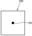
- 5A and 5B are perspective and central cross-sectional views of the third sub-module 230 of the center point measuring module 200 shown in FIG. 2.
- FIG. 6 schematically shows a method of guaranteeing quality of a radiation center point of a radiation treatment apparatus according to an embodiment of the present invention.
- FIG. 7 shows an example of the shape of the center point measuring module 200 that appears in the process of measuring the radiation center point according to FIG. 6.
- FIG. 8 schematically shows a functional block of a system for quality assurance of a radiation center point according to an embodiment of the present invention.
- FIG. 9 schematically shows a process of calculating a radiation center point according to an embodiment of the present invention.
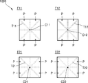
- FIG. 10 is a screen in which the positions of the two-dimensional radiation centers C11, C12, C21, and C22 are obtained from the imaging result 1000 of the radiation traces T11, T12, T21, and T22 according to an embodiment of the present invention. Shows an example.
- FIG. 11 illustrates an example of a screen in which two-dimensional radiation centers C11, C12, C21, and C22 are projected on a coordinate system of a three-dimensional treatment room according to an embodiment of the present invention.
- FIG. 12 shows an example of a screen in which a radiation center point (RI) on a coordinate system of a 3D treatment room is calculated according to an embodiment of the present invention.
- RI radiation center point
- FIG. 13 is a graph for verifying quality assurance for a radiation center point (RI) on a 3D treatment room coordinate system according to an embodiment of the present invention.
- the x-axis, y-axis, and z-axis used in the present specification are not limited to three axes on a Cartesian coordinate system, and may be interpreted in a broad sense including them.
- the x-axis, y-axis, and z-axis may be orthogonal to each other, but may refer to different directions that are not orthogonal to each other.
- the radiation treatment apparatus described in the present specification includes a diagnosis and treatment apparatus using radiation.
- FIG. 1 schematically shows a system for quality assurance of a radiation center point of a radiation treatment apparatus according to an embodiment of the present invention.
- the quality assurance system 10 of the radiation center point may be inserted into a radiation treatment apparatus 100 including a gantry 110 and a radiation irradiation unit 120, and a partial area of the radiation irradiation unit 120. It may include a collimator 130, a center point measurement module 200 used to measure the radiation center point. In addition, the quality assurance system 10 of the radiation center point may further include a camera unit 140, a bed unit 150, and a laser unit 160.
- the gantry 110 is a device capable of rotating around a patient during radiation treatment.
- the gantry 110 may be formed to have a cylindrical opening in the center as illustrated in FIG. 1, but is not limited thereto and may be implemented in various shapes capable of rotating around a patient.
- the gantry 110 has an empty space by a predetermined distance from the rotation axis and is rotatable around the rotation axis.
- the gantry 110 may rotate in the circumferential direction.
- the empty space is required for the patient or bed unit 150 to be disposed.
- the center point measurement module 200 may be disposed in the space.
- a radiation irradiation unit 120 protruding toward the rotation center (or rotation axis) may be coupled to the gantry 110.
- the radiation irradiation unit 120 may be coupled to the inner surface of the opening to protrude toward the rotation center of the gantry 110.
- the radiation irradiation unit 120 may emit or irradiate radiation.
- the radiation irradiation unit 120 is connected to an X-ray generator, a radiation isotope source, or a linear accelerator, or receives a high-energy particle ray beam generated from an incident accelerator installed outside the radiation treatment device 100. Can be released.
- the radiation irradiation unit 120 is installed on the gantry 110 so as to protrude toward the rotation axis of the gantry 110 and is rotatable together with the gantry 110. Accordingly, as the gantry 110 rotates, the radiation irradiation unit 120 may irradiate the radiation toward the center of the gantry 110 (ie, the rotation axis).
- the radiation irradiation unit 120 may irradiate the irradiated object while rotating around the object to be irradiated.
- the radiation irradiated to the irradiated object may include X-rays, gamma rays, high-energy electrons, high-energy protons, or other high-energy particle rays.
- the irradiated object becomes a patient, and when performing quality assurance of the radiation center point, the irradiated object may become the center point measuring module 200.
- a collimator 130 may be mounted or inserted into the radiation irradiation unit 120.
- the collimator 130 may be inserted in the front surface where the radiation is emitted from the radiation irradiation unit 120.
- the collimator 130 is a mechanism for limiting the direction and diffusion of radiation, and may be made of, for example, a material that absorbs radiation.
- the collimator 130 may be inserted into a distal end of the radiation irradiation unit 120, for example, a snout. When the collimator 130 is inserted, the radiation may be emitted through the collimator 130.
- the collimator 130 may be designed, assembled, or configured to irradiate radiation in an elongated rectangular shape for measuring a radiation center point.
- a slit may be inserted into the collimator 130.
- the collimator 130 may be formed so that radiation passes only through a slit having a linear or elongated rectangular shape.
- radiation may be irradiated through the slit to measure the radiation center point.
- the collimator 130 according to various embodiments of the present disclosure is not limited to including a slit.
- the collimator 130 may include a multi-leaf collimator (MLC) so as to form radiation in an elongated rectangular shape.
- MLC multi-leaf collimator
- the collimator 130 according to various embodiments of the present disclosure may use various methods to form radiation having an elongated rectangular shape.
- the bed part 150 is a support on which the patient can lie down during radiation treatment.
- the bed part 150 may enter an empty space formed at the center of rotation of the gantry 110. Accordingly, the bed portion 150 may be disposed substantially parallel to the rotation axis of the gantry 110, but is not limited thereto.
- the bed portion 150 may move left and right and/or up and down, and may rotate so that radiation may be irradiated to the patient's affected area.
- the center point measurement module 200 may be disposed on the bed part 150. However, it is not limited thereto.
- the center point measurement module 200 may be supported on a narrow support from which the bed portion 150 is removed.
- the radiation isocenter may mean a point at which radiations irradiated from various angles through the radiation irradiation unit 120 in the radiation treatment apparatus 100 are collected.
- the radiation center point may mean a point defined in a 3D space by centerlines of beams irradiated at various angles in the 3D space.
- the radiation center point may mean a point defined by intersections of radiation irradiated while rotating the gantry 110 and the collimator 130.
- the radiation center point is defined as a single point in a three-dimensional space, but may not appear as a single point in actual situations. Therefore, precise quality assurance for these radiation center points is required.
- the laser unit 160 may irradiate the laser beam LB toward an empty space formed at the center of rotation of the gantry 110.
- the laser beam LB may visually display a reference point at which the affected part of the patient is located. Accordingly, the laser beam LB may have a visible light band in order to be visually displayed inside the radiation treatment room, and may be displayed as a single dot on the irradiated object.
- One point displayed by the laser beam LB may be referred to as a laser isocenter.
- the laser center point may serve to visually guide a point at which an affected area to be subjected to radiation treatment is located.
- a three-dimensional coordinate system having the laser center point as an origin (0, 0, 0) may represent a treatment room coordinate system representing an actual three-dimensional treatment room space.
- the laser center point visually represents the center (origin) of the treatment room coordinate system.
- quality assurance for the radiation center point includes matching the radiation center point and the laser center point (eg, positioning within a specified distance (eg, 1 mm)).
- the position of the radiation center point in the treatment room coordinate system with the laser center point as (0, 0, 0) may be determined or obtained.
- Such coordinates of the center point of the radiation relative to the center point of the laser represent the coordinates of the center point of the radiation in an independent three-dimensional treatment room space itself. (That is, it is not measured by a sub-system (eg, an imaging device) included in the radiation treatment device 100.)
- the center point measurement module 200 is used to measure the radiation center point.
- the center point measurement module 200 in order to measure the radiation center point when performing quality assurance on the radiation center point, is disposed at the laser center point. A detailed description of the center point measurement module 200 will be described later with reference to FIGS. 2 to 5.
- the camera unit 140 may track the movement of the center point measurement module 200 by photographing a marker that can be attached to the center point measurement module 200.
- the camera unit 140 may include, for example, at least three or more cameras, and each of the plurality of cameras may be disposed to face different directions.
- the camera unit 140 may recognize the marker in various ways. For example, in addition to the camera, additional equipment is added to reflect light such as infrared light to the marker to track the marker's position, and the camera tracks the marker's position by emitting light directly from the marker. There is an active marker method.
- an infrared (IR) marker may be attached to the center point measurement module 200, and the marker may reflect infrared rays emitted from a separate infrared generator (not shown).
- the camera unit 140 is an infrared camera and may recognize infrared rays reflected from the marker. The camera unit 140 may acquire the position of the marker by photographing infrared rays reflected from the marker.
- the coordinates of the marker acquired through the camera unit 140 may be coordinates on a camera coordinate system.
- the camera coordinate system can be distinguished from the treatment room coordinate system representing the actual three-dimensional treatment room space.
- the camera unit 140 may convert the coordinates of the marker (or the position of the center point measurement module 200) into the treatment room coordinate system using a conversion relationship between the camera coordinate system and the treatment room coordinate system.
- the camera unit 140 may transform the camera coordinate system into a treatment room coordinate system using a transformation matrix between the camera coordinate system and the treatment room coordinate system.
- the coordinates of the marker tracked using the camera unit 140 may be positioned on the treatment room coordinate system with the laser center point as the origin. Through this, it is possible to track the coordinates of the marker in the treatment room coordinate system.
- the camera unit 140 may track the movement of the center point measuring module 200 in the coordinate system of the treatment room in three dimensions in real time.
- the camera unit 140 for tracking motion it is possible to independently measure the radiation center point without using an imaging device dependent on the radiation treatment apparatus 100. That is, the radiation center point can be obtained as a coordinate on a three-dimensional coordinate system representing an actual three-dimensional treatment room space. Through this, it is possible to perform independent three-dimensional quality assurance for the radiation center point.
- the vertical direction toward the top of the gantry 110 is parallel to the (ideal) axis of rotation of the gantry 110 based on the laser center point, which is the origin of the treatment room coordinate system, and the gantry 110 ) Will be referred to as the y-axis direction, and the horizontal direction according to the right-hand rule of the y-axis and z-axis as the x-axis direction.
- this reference is only an example.
- FIG. 2 is a perspective view of a center point measuring module 200 according to an embodiment of the present invention.
- the center point measurement module 200 may include a first sub-module 210, a second sub-module 220, and a third sub-module 230.
- 3 is an exploded perspective view of the first sub-module 210 of the center point measurement module 200 shown in FIG. 2
- FIG. 4 is an exploded perspective view of the second sub-module 220 of the center point measurement module 200 shown in FIG.
- FIGS. 5A and 5B are perspective and central cross-sectional views of the third sub-module 230 of the center point measuring module 200 shown in FIG. 2.
- the first sub-module 210, the second sub-module 220, and the third sub-module 230 are illustrated as a cube, but are not limited thereto.
- the first, second, and third sub-modules 210, 220, and 230 may include three pairs of parallel planes in which two facing surfaces are parallel.
- the first, second, and third sub-modules 210, 220, and 230 may be a rectangular parallelepiped. However, it is not limited thereto.
- the first, second, and third sub-modules 210, 220, and 230 may be fixed so that their relative positions do not change.
- the first, second, and third sub-modules 210, 220, and 230 may be attached to each other or fixedly coupled to each other.
- the center point measurement module 200 may further include a base 201 for fixing the first, second, and third sub-modules 210, 220, and 230.
- the first sub-module 210 may include a body 210B, a cover 210C, a pin P, and a pair of a first radiation reactive member F1
- the second sub-module 220 may include a body It may include a pair (220B), a cover (220C), a pin (P), and a second radiation reactive member (F2).
- two radiation reaction members F1 and F2 facing each other may be disposed in parallel.
- the first sub-module 210 may include two radiation-reactive members F1 parallel to the xy plane, and the second sub-module 220 may include two radiation-reactive members F2 parallel to the xz plane. It may include.
- the third sub-module 230 may not include a radiation reactive member.
- the radiation-reactive members F1 and F2 may react to radiation, and traces may be left by the radiation. Accordingly, the radiation-reactive members F1 and F2 may leave traces along the path of the radiation irradiated from the radiation irradiation unit 120.
- the radiation reaction members F1 and F2 may be developed or imaged (or digitized) using the scanner 170. For example, as a result of the digitization, a value indicating a location and coordinates corresponding to the path of the radiation may be obtained.
- the radiation reactive members F1 and F2 may include, for example, a radiochromic film.
- the radiation trace may be visualized using a camera instead of the scanner 170.
- the first sub-module 210 may include a body 210B and two covers 210C disposed above and below the body 210B.
- the two covers 210C may be provided to fix the two first radiation reactive members F1 above and below the body 210B, respectively.
- the second sub-module 220 may include a body 220B and two covers 220C disposed before and after the body 220B, respectively.
- the two covers 220C may be provided to fix the two second radiation reactive members F2 before and after the body 220C, respectively.
- the cover 210C may be disposed on two surfaces parallel to the xy plane (ie, the upper surface and the lower surface) in the first sub-module 210.
- the cover 210C may be provided to insert and fix the pair of the first radiation-reactive members F1 parallel to the xy plane (eg, on the upper and lower surfaces).
- the cover 210C is detachable from the body 210B of the first sub-module 210 in order to insert the radiation reaction member.
- the two radiation reactive members F1 may be disposed between the two covers 210C and the body 210B, respectively.
- the radiation reaction member F1 may be fixed with a pin P so that it does not move between the cover 210C and the body 210B.
- the pin P may be provided or inserted in a predetermined position in the cover 210Cs.
- the pins P may include a plurality (eg, two or more) of pins.
- the radiation-reactive member F1 has a square shape, and the pin P may be positioned adjacent to the vertex of the square.
- the four pins may be positioned in a rectangular shape.
- holes may be formed at positions corresponding to the positions of the pins P as many as the number of pins P.
- the hole may be used to identify the relative position information of the radiation trace appearing on the radiation-reactive member F1, as described later in FIGS. 9 to 11.
- the first sub-module 210 may further include a marker M (see FIG. 7 ).
- a marker M For example, at a predetermined position ML of the cover 210C of the first sub-module 210, a screw on which the marker M is attached may be fixed.
- the marker M is recognized by the camera unit 140 and is used to indicate the position of the center of the radiation trace appearing on the radiation-reactive member F1 or the radiation-responsive member F1 on the coordinate system of the three-dimensional treatment room.
- the marker M may be disposed on a surface on which the radiation reactive member F1 is disposed.
- the marker M is located adjacent to the pin P, but may be coupled to a predetermined position.
- the marker M may be coupled to the cover 210C.
- the positions of the marker M and the pin P are determined in advance, and their relative positions do not change. That is, the marker M and the pin P may be regarded as rigid bodies.
- a cover 220C may be disposed on two surfaces parallel to the xz plane (ie, front and rear).
- the cover 220C may be provided to insert and fix the pair of second radiation-reactive members F2 parallel to the xz plane (for example, on the front and rear surfaces).
- the two radiation-reactive members F2 may be disposed between the two covers 220C and the body 220B, respectively.
- the radiation-reactive member F2 may be fixed with a pin P so as not to move between the cover 220C and the body 220B.
- the description of the cover 220C, the body 220B, and the pin P will be omitted since it overlaps with that described in the first sub-module 210.
- the second sub-module 220 may further include a marker M (see FIG. 7 ).
- a screw on which the marker M is attached may be fixed to a predetermined position ML of the cover 220C of the second sub-module 220.
- the marker M is recognized by the camera unit 140 and is used to indicate the position of the center of the radiation trace appearing on the radiation-reactive member F2 or the radiation-reactive member F2 on the coordinate system of the three-dimensional treatment room.
- the third sub-module 230 may be arranged such that the center of the third sub-module 230 coincides with the laser center point when performing quality assurance on the radiation center point.
- a crosshair 239 may be displayed on the surface of the third sub-module 230.
- the third sub-module 230 has a shape of a cube, and a crosshair 239 for indicating the center of the third sub-module 230 may be displayed on each surface of the cube.
- the third sub-module 230 may further include a metal sphere 231 at the center.
- 5B is a cross-sectional view of the third sub-module 230 taken away.
- the third sub-module 230 may appear as in the cross-sectional view of FIG. 5B.
- the metal sphere 231 may be used to measure a center point of an imaging device (not shown) additionally installed in the radiation treatment apparatus 100.
- the center point of the imaging device represents a center point of an image imaged and reconstructed by the imaging device, which is distinct from the radiation center point and the laser center point.
- the first, second, and third sub-modules 210, 220, and 230 may all have a shape of a cube having the same length of one side. According to an embodiment, the first and second sub-modules 210 and 220 with respect to the third sub-module 230 may be fixed to each other in a vertical direction.
- the first sub-module 210 when the center point measurement module 200 is positioned at the laser center point in order to measure the radiation center point, the first sub-module 210 is in the -y-axis direction of the third sub-module 230
- the second sub-module 220 may be in contact with the surface of the third sub-module 230 in the -x-axis direction.
- all of the first, second, and third sub-modules 210, 220, and 230 may have a cube shape having the same length L of one side.
- the height (thickness) of the body 210B and the two lids 210C in the first sub-module 210 it may correspond to the length L of one side of the cube.
- the thickness of the body 220B (ie, the length in the y-axis direction) and the thickness of the two lids 220C are added in the second sub-module 220, it may correspond to the length L of one side of the cube.
- a distance between the center of the first sub-module 210 and the center of the third sub-module 230 may be the same as the length L of one side.
- the distance between the center of the second sub-module 220 and the center of the third sub-module 230 is also the same as the length L of one side.
- the length L of one side may be, for example, 10 cm.
- the two lids 210C of the first sub-module 210 may have the same thickness TH1.
- the thickness TH1 may be, for example, 1 cm.
- the pair of the first radiation-reactive members F1 included in the first sub-module 210 is disposed to be spaced apart from the center of the first sub-module 210 by the same distance (eg, 4 cm) in the ⁇ z-axis direction. I can.
- the two lids 220C of the second sub-module 220 may have the same thickness TH2.
- the thickness TH2 may be, for example, 1 cm.
- the pair of the second radiation-reactive members F2 included in the second sub-module 220 are to be disposed spaced apart from the center of the second sub-module 220 by the same distance (eg, 4 cm) in the ⁇ y-axis direction. I can.
- the thickness TH1 of the two lids 210C of the first sub-module 210 and the thickness TH2 of the two lids 220C of the second sub-module 220 are It can be the same.
- the quality assurance system 10 of the radiation center point of the radiation treatment apparatus further includes a control unit (not shown) that controls the rotation of the gantry 110 and irradiation of radiation through the radiation irradiation unit 120.
- the control unit may be formed of hardware, software, or a combination of hardware and software.
- the control unit may include one or more control units.
- the control unit referred to in the present invention may be a term that collectively refers to a control unit of a plurality of devices.
- the controller may control the movement of the support of the center point measurement module 200 so that the center point measurement module 200 is positioned at the laser center point.
- the control unit may match the center of the first sub-module 210, the second sub-module 220, or the third sub-module 230 to the center point of the laser, the support of the center point measuring module 200 You can control the movement.
- the support may be, for example, the bed part 150, but is not limited thereto.
- the support may represent a support from which the bed portion 150 is removed.
- the controller may control the rotation of the gantry 110, and accordingly, may position the radiation irradiation unit 120 at a desired angle. According to an embodiment, the controller may control the rotation of the collimator 130 inserted into the radiation irradiation unit 120. For example, the control unit may rotate the collimator 130 inserted in the radiation irradiation unit 120 by a desired angle. According to an embodiment, the control unit may control the radiation irradiation unit 120 to irradiate radiation.
- FIG. 6 schematically shows a method of guaranteeing quality of a radiation center point of a radiation treatment apparatus according to an embodiment of the present invention. At least some of the operations shown in FIG. 6 may be performed by the controller. 7 shows an example of the shape of the center point measuring module 200 that appears in the process of measuring the radiation center point according to FIG. 6.
- a collimator 130 configured to form radiation in an elongated rectangular shape may be inserted into the radiation irradiation unit 120.
- the collimator 130 may be inserted into a distal end of the radiation irradiation unit 120, for example, a snout.
- the center point measuring module 200 may be disposed at the center point of the laser indicated by the laser beam by the laser unit 160.
- the control unit may position the center point measurement module 200 so that the center of the third sub-module 230 is positioned at the laser center point in the center point measurement module 200.
- a state in which the center of the third sub-module 230 and the laser center point coincide may be an initial setting state of the center point measurement module 200.
- the center of the third sub-module 230 may be matched to the center point of the laser by using the crosshairs displayed on the surface of the third sub-module 230.
- the center of the pair of the first radiation-reactive members F1 included in the first sub-module 210 is placed at the laser center point, the gantry 110 is fixed and the collimator 130 is rotated, for example, a collimator.
- the collimator 130 is rotated, for example, a collimator.
- MLC multi-leaf collimator
- the center of the pair of the first radiation reactive members F1 may represent the center of the first sub-module 210.
- the control unit moves the center point measuring module 200 in the y-axis direction. It can be moved by a distance from the center of the module 230 to the center of the first sub-module 210.
- the center point measuring module 200 is moved in the y-axis direction in the initial setting state.
- the center of the first sub-module 210 may be disposed at the center point of the laser.
- the pair of the first radiation-reactive members F1 is located at a distance from the center point of the laser by the same distance in the z direction and the -z direction. can do.
- the control unit rotates the gantry 110 in a state in which the center of the first sub-module 210 is disposed at the center point of the laser, so that the radiation irradiation unit 120 is positioned above the center point measurement module 200.
- the gantry 110 may be fixed so as to be performed. That is, the gantry 110 may be fixed so that the radiation irradiation unit 120 is positioned on the z-axis. In this case, the radiation irradiation unit 120 protruding from the gantry 110 may face the -z axis direction.
- the radiation irradiation unit 120 may aim at the first sub-module 210 from a vertical upper portion of the first sub-module 210.
- the control unit may irradiate radiation while rotating the collimator 130 in a state in which the gantry 110 is fixed so that the radiation irradiation unit 120 faces the -z-axis direction as described above.
- the control unit may control the radiation irradiation unit 120 to irradiate radiation while rotating the collimator 130 at specified angular intervals.
- the specified angle may be 45 degrees, for example.
- the radiation irradiation unit 120 may irradiate radiation in a state in which the collimator 130 is 0 degrees, 45 degrees, 90 degrees, and 135 degrees.
- the rotation angle of the collimator 130 to which radiation is irradiated is not limited thereto.
- radiation may be irradiated through a slit formed in the collimator 130 or a multi-leaf collimator (MLC). Therefore, in a state in which the gantry 110 is fixed so that the radiation irradiation unit 120 is positioned above the center point measurement module 200, the result of irradiating the radiation when the collimator 130 is at 0 degrees, 45 degrees, 90 degrees, and 135 degrees.
- a trace of radiation T1 may appear in a star shape.
- the trace T1 may represent a distribution of radiation dose.
- the first, second, and third sub-modules 210, 220, and 230 are all cube-shaped with the same length of one side, and the first pair of radiation-reactive members F1 and the second pair of radiation-reactive members F2 are Due to the positional relationship, a trace of radiation may not appear in the second pair of radiation-reactive members F2 according to the rotation of the collimator 130 (S630).
- the center of the pair of second radiation reactive members F2 included in the second sub-module 220 is placed at the laser center point, the collimator 130 is fixed and the gantry 110 is rotated, while the collimator 130 Through this, radiation may be irradiated to the pair of the second radiation reactive members F2.
- the center of the pair of second radiation reactive members F2 may represent the center of the second sub-module 220.
- the control unit moves the center point measuring module 200 in the x-axis direction in the above-described initial setting state. It can be moved by a distance from the center of the module 230 to the center of the second sub-module 220.
- the center point measuring module 200 is moved in the x-axis direction in the initial setting state.
- the center of the second sub-module 220 may be disposed at the center point of the laser.
- the pair of the second radiation-reactive members F2 are positioned at a distance equal to the same distance in the y direction and the -y direction from the laser center point. can do.
- the collimator 130 is rotated while the center of the second sub-module 220 is placed at the center point of the laser, so that the long axis of the long rectangle, which is the shape of the cross section of the radiation formed by the collimator 130, is
- the collimator 130 may be fixed to be parallel to the y-axis (ie, the rotation axis of the gantry 110).
- the control unit fixes the collimator 130 so that the long rectangular long axis, which is the cross section of the radiation of the collimator 130, is parallel to the y axis (ie, the rotation axis of the gantry 110) as described above.
- the control unit may control the gantry 110 to irradiate radiation by rotating the gantry 110 at a specified angular interval.
- the specified angle may be 45 degrees, for example.
- radiation may be irradiated in a state in which the gantry 110 is 0 degrees, 45 degrees, 90 degrees, or 135 degrees.
- a rotation angle of 0 degrees of the gantry 110 may represent, for example, a state in which the radiation irradiation unit 120 is positioned on the z-axis and points in the -z-axis direction.
- the definition of the rotation angle of the gantry 110 is not limited thereto.
- the rotation angle of the gantry 110 to which radiation is irradiated is not limited thereto.
- a trace of radiation T2 may appear in a star shape.
- the trace T2 may represent a distribution of radiation dose.
- FIG. 7 shows only the radiation-reactive member F2 disposed on the front surface of the second sub-module 220 (eg, a surface located in the -y-axis direction), but the rear surface of the second sub-module 220 (eg, +y In the radiation-reactive member F2 disposed on the surface located in the axial direction), traces of radiation appear in a star shape.
- the first, second, and third sub-modules 210, 220, and 230 are all cube-shaped with the same length of one side, and the first pair of radiation-reactive members F1 and the second pair of radiation-reactive members F2 are Due to the positional relationship, traces of radiation may not appear in the pair of the first radiation reactive members F1 according to the rotation S640 of the gantry 110.
- the order of operations included in S630 and S640 may be changed.
- the order of S630 and S640 may be changed.
- the radiation center point may be calculated from positional information corresponding to the traces of radiation displayed on the first pair of radiation-responsive members F1 and the second pair of radiation-responsive members F2. Detailed operations for S650 will be described later in FIGS. 8 to 12.
- S650 is shown in FIG. 8, a scanner 170 (or an imaging device such as a camera), a two-dimensional radiation center acquisition unit 370, a camera unit 140, a marker coordinate conversion unit 340, and a three-dimensional coordinate It may be performed by the calculation unit 390.
- FIG. 8 schematically shows a functional block of a system for quality assurance of a radiation center point according to an embodiment of the present invention.
- 9 schematically shows a process of calculating a radiation center point according to an embodiment of the present invention. Operations shown in FIG. 9 may be included in S650 of FIG. 6.
- the controller 180 may control the rotation of the gantry 110 and irradiation of radiation through the radiation irradiation unit 120 as described above.
- the controller 180 may control the movement of the support of the center point measurement module 200 so that the center point measurement module 200 is positioned at the laser center point.
- the control unit 180 performs at least a part of the operations included in S620 to S640 of FIG. 6, so that the radiation traces T1 and T2 may appear on the radiation reaction members F1 and F2 of the center point measurement module 200.
- the pair of first radiation-reactive members F1 includes a first radiation-reactive member F11 on an upper surface (a surface in the z-axis direction) and a first radiation-reactive member F12 on a lower surface (a surface in the -z-axis direction).
- a radiation trace T11 may appear on the first radiation reactive member F11 on the upper surface
- a radiation trace T12 may appear on the first radiation reactive member F12 on the lower surface.
- the pair of second radiation-reactive members (F2) includes a second radiation-reactive member (F21) on the front surface (a surface in the -y-axis direction) and a second radiation-reactive member (F22) on the rear surface (a surface in the y-axis direction), ,
- a radiation trace T21 may appear on the first radiation reactive member F21 on the front side
- a radiation trace T22 may appear on the second radiation reaction member F22 on the rear surface.
- an imaging apparatus including a scanner 170 or a camera includes a radiation trace T11, which is shown on a pair of the first radiation-reactive member F1 and the second radiation-reactive member F2.
- T12, T21, T22) can be imaged (or digitized).
- the imaging may represent imaging on a 2D plane.
- the scanner 170 or the imaging apparatus may transmit the imaged result to the 2D radiation center acquisition unit 370.
- the two-dimensional radiation center acquisition unit 370 from the scanner 170 or the imaging device, the radiation traces (T11, T12, T21, T22) appearing on the first and second radiation reactive members (F1, F2).
- the imaging result can be received.
- the 2D radiation center acquisition unit 370 includes 2 of the radiation traces T11, T12, T21, and T22 appearing on the first pair of radiation reactive members F1 and the second pair of radiation reactive members F2. The positions of the dimensional centers can be obtained.
- the two-dimensional radiation center acquisition unit 370 is, from the radiation traces T11 and T12 appearing on each of the two first radiation-reactive members F11 and F12, the first two-dimensional radiation center C11, You can calculate the position of C12).
- Each of the first two-dimensional radiation centers C11 and C12 represents the center of the star-shaped radiation traces T11 and T12.
- the first two-dimensional radiation centers C11 and C12 represent centers according to the rotation of the collimator 130.
- the two-dimensional radiation center acquisition unit 370 from the radiation traces (T21, T22) appearing on each of the two second radiation response members (F21, F22), the position of the second two-dimensional radiation center (C21, C22). Can be calculated.
- the second two-dimensional radiation centers C21 and C22 represent centers according to the rotation of the gantry 110.
- the imaging result 1000 of the radiation traces T11, T12, T21, and T22 may include a pin P trace.
- the pin (P) trace is later used to indicate the positions of the two-dimensional radiation centers C11, C12, C21, C22 on the three-dimensional treatment room coordinate system.
- the two-dimensional radiation center acquisition unit 370 from the imaging result 1000, the pins P shown in the pair of the first radiation reactive members F11 and F12 and the pair of the second radiation reactive members F21 and F22. Can identify the location of.
- the pin (P) moves as a rigid body with the marker (M)
- the location of the pin (P) may also be indicated on the 3D treatment room coordinate system. Accordingly, the 2D radiation centers C11, C12, C21, C22 can be represented on the 3D treatment room coordinate system based on the position of the pin P on the 3D treatment room coordinate system.
- the two-dimensional radiation center acquisition unit 370 calculates the positions of the two-dimensional radiation centers C11, C12, C21, C22 obtained from the imaging result 1000 and the positions of the plurality of pins P, 3D coordinates. It can be transmitted to the unit 390.
- the positions of the two-dimensional radiation centers C11, C12, C21, and C22 and the positions of the plurality of pins P may be coordinates in two dimensions.
- the two-dimensional radiation center acquisition unit 370 determines the relative positions of the two-dimensional radiation centers C11, C12, C21, and C22 based on the positions of the plurality of pins P in three-dimensional coordinates. It may be transmitted to the calculation unit 390.
- the three-dimensional coordinate calculation unit 390 is, from the two-dimensional radiation center obtaining unit 370, relative to the two-dimensional radiation centers C11, C12, C21, C22 based on the positions of the plurality of pins P. You can receive information about the location.
- the camera unit 140 can recognize the position of the marker M on the center point measurement module 200, and the camera unit 140 is the position of the marker M obtained on the camera coordinate system. May be transmitted to the marker coordinate conversion unit 340.
- the marker coordinate conversion unit 340 may convert the position of the marker M into the treatment room coordinate system using a transformation matrix between the camera coordinate system and the treatment room coordinate system. In the marker coordinate conversion unit 340, the transformation matrix may be stored.
- the marker coordinate conversion unit 340 may acquire the coordinates of the marker M in the 3D treatment room coordinate system using the transformation matrix.
- the marker coordinate conversion unit 340 may transmit the coordinates of the marker M in the coordinate system of the 3D treatment room to the 3D coordinate calculator 390.
- the 3D coordinate calculation unit 390 includes the positions of the plurality of pins P received from the 2D radiation center acquisition unit 370 and the coordinates of the marker M received from the marker coordinate conversion unit 340 Using, the positions of the 2D radiation centers C11, C12, C21, C22 can be represented (or projected) on the coordinate system of the 3D treatment room. That is, the 3D coordinate calculation unit 390 may calculate the coordinates of the 2D radiation centers C11, C12, C21, and C22 on the 3D treatment room coordinate system.
- FIG. 11 illustrates an example of a screen in which two-dimensional radiation centers C11, C12, C21, and C22 are projected on a coordinate system of a three-dimensional treatment room according to an embodiment of the present invention.
- the graph shown in Fig. 11 shows an actual three-dimensional treatment room coordinate system with the laser center point as the origin.
- the 3D coordinate calculation unit 390 Since the pin (P) moves as a rigid body with the marker (M), when acquiring the position of the marker (M) in the 3D treatment room coordinate system, the 3D coordinate calculation unit 390 is The position of P) can also be calculated. Accordingly, the 3D coordinate calculator 390 may acquire the positions of the 2D radiation centers C11, C12, C21, and C22 based on the position of the pin P in the 3D treatment room coordinate system. That is, the 3D coordinate calculator 390 may calculate coordinates of the 2D radiation centers C11, C12, C21, and C22 in the 3D treatment room coordinate system.
- the three-dimensional coordinate calculation unit 390 uses the coordinates of the two-dimensional radiation centers C11, C12, C21, C22 in the three-dimensional treatment room coordinate system, and the first according to the rotation of the collimator 130
- the center line L1 and the second center line L2 according to the rotation of the gantry 110 may be obtained.
- the first center line L1 according to the rotation of the collimator 130 may be parallel to the line connecting the first two-dimensional radiation centers C11 and C12, and the rotation of the gantry 110 Accordingly, the second center line L2 may be parallel to a line connecting the second 2D radiation centers C21 and C22.
- the first, second, and third sub-modules 210, 220, and 230 may be a cube having one side length L.
- the first center line L1 according to the rotation of the collimator 130 is a line in which the line connecting the first two-dimensional radiation centers C11 and C12 is moved in parallel by L in the y-axis direction.
- the second center line L2 according to the rotation of the gantry 110 may be a line in which a line connecting the second 2D radiation centers C21 and C22 is moved in parallel by L in the x-axis direction.
- the first center line L1 is irradiated with radiation while rotating the collimator 130.
- the second center line L2 is a state in which the collimator 130 is fixed so that the slit of the collimator 130 or the axis of the multi-leaf collimator MLC is parallel to the y-axis, while rotating the gantry 110, the radiation hat is irradiated. In this case, a line that becomes the center of the radiation may be indicated.
- the 3D coordinate calculator 390 may calculate or obtain a linear equation of the first center line L1 and the second center line L2 in the 3D treatment room coordinate system.
- the 3D coordinate calculator 390 may determine an intersection point of the first center line L1 and the second center line L2 as the radiation center point RI.
- FIG. 13 is a graph for verifying quality assurance for a radiation center point (RI) on a 3D treatment room coordinate system according to an embodiment of the present invention.
- the graph shown in FIG. 13 may be a three-dimensional treatment room coordinate system with a laser center point as an origin.
- the 3D coordinate calculator 390 may determine whether the radiation center point RI is located within a specified distance from the laser center point.
- the specified distance may be, for example, 1 mm or 0.5 mm.
- the 3D coordinate calculating unit 390 may determine that the quality of the radiation center point RI is guaranteed when the radiation center point RI is located within the specified distance from the laser center point.
Landscapes
- Health & Medical Sciences (AREA)
- Life Sciences & Earth Sciences (AREA)
- Medical Informatics (AREA)
- Engineering & Computer Science (AREA)
- Radiology & Medical Imaging (AREA)
- Molecular Biology (AREA)
- Biophysics (AREA)
- Nuclear Medicine, Radiotherapy & Molecular Imaging (AREA)
- Optics & Photonics (AREA)
- Pathology (AREA)
- Physics & Mathematics (AREA)
- Biomedical Technology (AREA)
- Heart & Thoracic Surgery (AREA)
- High Energy & Nuclear Physics (AREA)
- Surgery (AREA)
- Animal Behavior & Ethology (AREA)
- General Health & Medical Sciences (AREA)
- Public Health (AREA)
- Veterinary Medicine (AREA)
- Radiation-Therapy Devices (AREA)
- Measurement Of Radiation (AREA)
Abstract
본 발명은, 회전축으로부터 이격된 공간을 가지고 상기 회전축을 중심으로 회전 가능한 갠트리와, 상기 갠트리에 고정되어 상기 갠트리와 함께 회전 가능하며, 상기 회전축을 향해 방사선을 조사하는 방사선 조사부와, 상기 방사선 조사부에 삽입될 수 있는 콜리메이터와, 상기 방사선 조사부를 통해 조사되는 방사선의 방사선 중심점을 측정하기 위해, 상면과 하면에서 서로 마주보며 평행한 제1 방사선 반응부재 쌍 및 전면과 후면에서 서로 마주보는 평행한 제2 방사선 반응부재 쌍을 포함하는 중심점 측정모듈과, 상기 갠트리의 회전과 상기 방사선 조사부를 통한 방사선의 조사를 제어하는 제어부와, 및 상기 제1 방사선 반응부재 쌍 및 상기 제2 방사선 반응부재 쌍에 나타난 방사선의 흔적에 대응 위치 정보로부터 상기 방사선 중심점을 산출하는 3차원 좌표 산출부를 포함하는, 방사선을 이용한 진단 및 치료 장치의 방사선 중심점의 품질 보증 시스템을 제공한다. 상기 제어부는 상기 갠트리를 고정시키고 상기 콜리메이터를 회전시키면서 상기 제1 방사선 반응부재 쌍에 방사선을 조사하고, 상기 콜리메이터를 고정시키고 상기 갠트리를 회전시키면서 상기 제2 방사선 반응부재 쌍에 방사선을 조사하여, 방사선 중심점을 획득할 수 있다.
Description
본 발명의 실시예들은, 방사선을 이용한 진단 및 치료 장치의 방사선 중심점(radiation isocenter)의 품질 보증 시스템 및 방법에 관한 것으로, 특히, 방사선 치료실을 구성하는 다양한 하위 장치들부터 독립적으로, 및 3차원적으로 방사선 중심점을 획득하는 방사선 중심점의 품질 보증 시스템 및 방법에 관한 것이다.
방사선 치료를 수행하기 위해서는, 방사선 치료실을 구성하는 모든 시스템들의 좌표계 간의 일치 여부에 대한 품질 보증이 반드시 요구된다. 구체적으로, 방사선 치료실을 구성하는 복수의 시스템들의 중심점(isocenter)들이 일치하는지 여부를 확인하고, 일치시키는 작업이 필요하다. 상기 복수의 시스템들의 중심점들을 일치시키지 않으면, 방사선 감수성이 높은 주변 조직에 대하여, 계획되지 않은 방사선량으로 인해 손상을 유발할 수 있다.
따라서, 방사선 치료 시스템에서, 방사선이 조사되는 중심점을 포함하는, 복수의 시스템들의 중심점의 일치 여부에 대한 품질 보증 시스템 및 방법이 요구된다.
상술한 바와 같은 방사선 중심점의 품질 보증은, 예를 들면, 방사선 반응 필름을 이용하여 수행될 수 있는데, 종래의 방법으로는 3차원 공간 상에 존재하는 방사선 중심점을 측정하지 못하며, 2차원 상의 방사선 중심점만을 측정하는 문제점이 있다.
또한, 방사선 치료 장치에 부착되는 이미징 장치(imaging device)를 이용하여 방사선 중심점을 측정하는 방법은, 상기 이미징 장치 자체의 정렬에 영향을 받으며, 독립적인 방사선 치료 장치의 방사선 중심점 자체를 측정하지 못하는 문제점이 있다. 즉, 방사선 치료 장치에 부착되는 이미징 장치(imaging device)를 이용하면, 이미징 장치의 좌표계에 대한 방사선 중심점이 측정될 뿐, 3차원의 치료실 공간 상에 독립적으로 존재하는 방사선 중심점을 측정하기 어렵다.
따라서, 본 발명은 상술한 문제점을 포함하여 여러 문제점들을 해결하기 위해 안출된 것으로, 주변 장치에 독립적인 3차원 상의 방사선 중심점을 측정할 수 있는, 방사선 중심점의 품질 보증 시스템 및 방법을 제공하는 것을 목적으로 한다. 그러나 이러한 과제는 예시적인 것으로, 이에 의해 본 발명의 범위가 한정되는 것은 아니다.
본 발명의 일 실시예에 따른, 방사선을 이용한 진단 및 치료 장치의 방사선 중심점의 품질 보증 시스템은, 회전축으로부터 이격된 공간을 가지고 상기 회전축을 중심으로 회전 가능한 갠트리; 상기 갠트리에 고정되어 상기 갠트리와 함께 회전 가능하며, 상기 회전축을 향해 방사선을 조사하는 방사선 조사부; 상기 방사선 조사부에 삽입될 수 있는 콜리메이터; 상기 방사선 조사부를 통해 조사되는 방사선의 방사선 중심점을 측정하기 위해, 상면과 하면에서 서로 마주보며 평행한 제1 방사선 반응부재 쌍 및 전면과 후면에서 서로 마주보는 평행한 제2 방사선 반응부재 쌍을 포함하는 중심점 측정모듈; 상기 갠트리의 회전과 상기 방사선 조사부를 통한 방사선의 조사를 제어하는 제어부; 및 상기 제1 방사선 반응부재 쌍 및 상기 제2 방사선 반응부재 쌍에 나타난 방사선의 흔적에 대응 위치 정보로부터 상기 방사선 중심점을 산출하는 3차원 좌표 산출부;를 포함하고, 상기 제어부는, 상기 갠트리를 고정시키고 상기 콜리메이터를 회전시키면서 상기 제1 방사선 반응부재 쌍에 방사선을 조사하고, 상기 콜리메이터를 고정시키고 상기 갠트리를 회전시키면서 상기 제2 방사선 반응부재 쌍에 방사선을 조사할 수 있다.
일 실시예에 따르면, 상기 중심점 측정모듈은, 상기 콜리메이터를 회전시키면서 조사되는 방사선의 제1 중심선을 획득하기 위한, 제1 서브 모듈; 상기 갠트리를 회전시키면서 조사되는 방사선의 제2 중심선을 획득하기 위한, 제2 서브 모듈; 및 상기 중심점 측정모듈의 초기 세팅 상태를 정렬하는 데 이용되는 제3 서브 모듈;을 포함할 수 있다.
일 실시예에 따르면, 상기 제1 서브 모듈, 상기 제2 서브 모듈, 상기 제3 서브 모듈은 한 변의 길이가 동일한 정육면체 모양이고, 상기 제3 서브 모듈의 표면에는, 제3 서브 모듈의 중심을 나타내기 위한 십자선이 표시되고, 상기 초기 세팅 상태는, 레이저빔이 시각적으로 나타내는 레이저 중심점과 상기 제3 서브 모듈의 중심이 일치하는 상태일 수 있다.
일 실시예에 따르면, 상기 중심점 측정모듈은, 상기 제1 방사선 반응부재 쌍 및 상기 제2 방사선 반응부재 쌍을 상기 중심점 측정모듈에 고정시키기 위한 핀; 및 카메라에 의하여 인식될 수 있는 마커;를 더 포함할 수 있다.
일 실시예에 따르면, 상기 품질 보증 시스템은, 상기 제1 방사선 반응부재 쌍 및 상기 제2 방사선 반응부재 쌍에 나타난 방사선 흔적을 영상화하기 위한 스캐너 또는 상기 카메라를 포함하는 영상장치; 및 상기 스캐너 또는 상기 카메라를 포함하는 영상장치에 의한 2차원으로 영상화 결과로부터, 상기 방사선 흔적의 2차원 중심을 획득하기 위한 2차원 방사선 중심 획득부;를 더 포함하고, 상기 2차원 방사선 중심 획득부는, 상기 핀의 위치를 기준으로 하는 상기 2차원 중심의 상대적인 위치를 획득할 수 있다.
일 실시예에 따르면, 상기 제어부는, 상기 제1 방사선 반응부재 쌍에 방사선을 조사할 때, 상기 방사선 조사부가 상기 제1 방사선 반응부재 쌍의 상부에 위치하도록 상기 갠트리를 고정시키고, 상기 콜리메이터를 지정된 각도 간격으로 회전시키면서 상기 제1 방사선 반응부재 쌍에 방사선을 조사할 수 있다.
일 실시예에 따르면, 상기 제어부는, 상기 제2 방사선 반응부재 쌍에 방사선을 조사할 때, 상기 방사선의 단면의 모양인 긴 직사각형 모양이 상기 회전축에 평행하도록 상기 콜리메이터를 고정시키고, 상기 갠트리를 지정된 각도 간격으로 회전시키면서 상기 제2 방사선 반응부재 쌍에 방사선을 조사할 수 있다.
본 발명의 일 실시예에 따른, 방사선을 이용한 진단 및 치료 장치의 방사선 중심점의 품질 보증 방법은, 회전축으로부터 이격된 공간을 가지고 상기 회전축을 중심으로 회전 가능한 갠트리를 포함하는 장치에서, 상기 회전축을 향해 방사선을 조사하는 방사선 조사부에, 콜리메이터를 삽입하는 단계; 상기 갠트리의 중심에 레이저빔이 나타내는 레이저 중심점에, 상면과 하면에서 서로 마주보며 평행한 제1 방사선 반응부재 쌍 및 전면과 후면에서 서로 마주보는 평행한 제2 방사선 반응부재 쌍을 포함하는 중심점 측정모듈을 배치하는 단계; 상기 제1 방사선 반응부재 쌍의 중심을 상기 레이저 중심점에 배치하고, 상기 갠트리를 고정시키고 상기 콜리메이터를 회전시키면서 상기 제1 방사선 반응부재에 방사선을 조사하는 단계; 상기 제2 방사선 반응부재 쌍의 중심을 상기 레이저 중심점에 배치하고, 상기 콜리메이터를 고정시키고 상기 갠트리를 회전시키면서 상기 제2 방사선 반응부재에 방사선을 조사하는 단계; 상기 제1 방사선 반응부재 및 상기 제2 방사선 반응부재 쌍에 나타난 방사선의 흔적에 대응하는 위치 정보로부터 방사선 중심점을 산출하는 단계;를 포함할 수 있다.
일 실시예에 따르면, 상기 방법은, 상기 제1 방사선 반응부재 쌍 및 상기 제2 방사선 반응부재 쌍에 나타난 방사선 흔적을, 스캐너 또는 카메라를 포함하는 영상장치를 이용하여 영상화하는 단계; 및 상기 영상화된 결과로부터, 상기 제1 방사선 반응부재 쌍 및 상기 제2 방사선 반응부재 쌍에 나타난 방사선 흔적의 2차원 중심들의 위치를 획득하는 단계;를 더 포함할 수 있다.
일 실시예에 따르면, 상기 중심점 측정모듈은, 상기 제1 방사선 반응부재 쌍 및 상기 제2 방사선 반응부재 쌍을 상기 중심점 측정모듈에 고정시키기 위한 핀 및 카메라에 의하여 인식될 수 있는 마커를 더 포함하고, 상기 방법은, 상기 핀의 위치 및 상기 마커의 위치를 이용하여, 상기 방사선 흔적의 2차원 중심들의 위치를, 3차원 치료실 좌표계로 투영하는 단계;를 더 포함할 수 있다.
일 실시예에 따르면, 상기 방법은, 상기 3차원 치료실 좌표계로 투영된 상기 방사선 흔적의 2차원 중심들의 위치를 이용하여, 상기 3차원 치료실 좌표계 상에서의 상기 방사선 중심점의 좌표를 산출하는 단계;를 더 포함할 수 있다.
전술한 것 외의 다른 측면, 특징, 이점이 이하의 도면, 특허청구범위 및 발명의 상세한 설명으로부터 명확해질 것이다.
상술한 바와 같이 이루어진 본 발명의 다양한 실시예에 따르면, 주변 시스템과는 독립적인 3차원 상의 방사선 중심점을 측정할 수 있는, 방사선 중심점의 품질 보증 시스템 및 방법을 제공할 수 있다. 다시 말하면, 방사선 중심점에 대한 품질 보증을 보다 정밀하게 수행할 수 있다. 또한 방사선 치료실을 구성하는 복수의 하위 시스템들에 대한 중심점들을, 3차원 좌표계에서 독립적으로 획득할 수 있으며, 따라서 상기 복수의 중심점들에 대한 독립적인 품질 보증을 수행할 수 있다.
방사선 중심점에 대한 정확한 품질 보증은, 종양 조직의 치료 계획 시에 마진(margin)을 줄일 수 있고, 정상 조직에 전달되는 계획되지 않은 방사선량을 최소화할 수 있다.
물론 이러한 효과에 의해 본 발명의 범위가 한정되는 것은 아니다.
도 1은 본 발명의 일 실시예에 따른 방사선 치료 장치의 방사선 중심점의 품질 보증 시스템을 개략적으로 도시한다.
도 2는 본 발명의 일 실시예에 따른 중심점 측정모듈(200)의 사시도이다.
도 3은 도 2에 도시된 중심점 측정모듈(200)의 제1 서브 모듈(210)의 분해 사시도이다.
도 4는 도 2에 도시된 중심점 측정모듈(200)의 제2 서브 모듈(220)의 분해 사시도이다.
도 5a 및 도 5b는 도 2에 도시된 중심점 측정모듈(200)의 제3 서브 모듈(230)의 사시도와 중심 단면도이다.
도 6은 본 발명의 일 실시예에 따른 방사선 치료 장치의 방사선 중심점의 품질 보증 방법을 개략적으로 나타낸다.
도 7은, 도 6에 따라 방사선 중심점을 측정하는 과정에서 나타나는 중심점 측정모듈(200)의 모습의 예를 도시한다.
도 8은 본 발명의 일 실시예에 따른 방사선 중심점의 품질 보증 시스템의 기능적 블록을 개략적으로 도시한다.
도 9는 본 발명의 일 실시예에 따른 방사선 중심점을 산출하는 과정을 개략적으로 나타낸다.
도 10은 본 발명의 일 실시예에 따른 방사선 흔적(T11, T12, T21, T22)의 영상화 결과(1000)로부터, 2차원 방사선 중심들(C11, C12, C21, C22)의 위치를 획득한 화면의 예를 도시한다.
도 11은 본 발명의 일 실시예에 따라 3차원 치료실 좌표계 상에 2차원 방사선 중심들(C11, C12, C21, C22)이 투영된 화면의 예를 도시한다.
도 12는 본 발명의 일 실시예에 따라 3차원 치료실 좌표계 상의 방사선 중심점(RI)이 계산된 화면의 예를 도시한다.
도 13은 본 발명의 일 실시예에 따라 3차원 치료실 좌표계 상에서 방사선 중심점(RI)에 대한 품질 보증을 검증하기 위한 그래프를 도시한다.
본 발명은 다양한 변환을 가할 수 있고 여러 가지 실시예들을 가질 수 있는 바, 특정 실시예들을 도면에 예시하고, 상세한 설명에 상세하게 설명하고자 한다. 그러나, 이는 본 발명을 특정한 실시 형태에 대해 한정하려는 것이 아니며, 본 발명의 사상 및 기술 범위에 포함되는 모든 변환, 균등물 내지 대체물을 포함하는 것으로 이해되어야 한다. 본 발명을 설명함에 있어서 관련된 공지 기술에 대한 구체적인 설명이 본 발명의 요지를 흐릴 수 있다고 판단되는 경우 그 상세한 설명을 생략한다.
본 명세서에서 사용되는 제1, 제2 등의 용어는 다양한 구성요소들을 설명하는데 사용될 수 있지만, 구성요소들은 용어들에 의해 한정되어서는 안 된다. 용어들은 하나의 구성요소를 다른 구성요소로부터 구별하는 목적으로만 사용된다.
본 명세서에서 사용되는 x축, y축, 및 z축은 직교 좌표계 상의 세 축으로 한정되지 않고, 이를 포함하는 넓은 의미로 해석될 수 있다. 예를 들어, x축, y축 및 z축은 서로 직교할 수도 있지만, 서로 직교하지 않는 서로 다른 방향을 지칭할 수도 있다.
이하, 본 발명에 따른 실시예들을 도면을 참조하여 상세히 설명하기로 하며, 도면을 참조하여 설명함에 있어 실질적으로 동일하거나 대응하는 구성 요소는 동일한 도면번호를 부여하고 이에 대한 중복되는 설명은 생략하기로 한다. 도면에서 여러 층 및 영역을 명확하게 표현하기 위하여 두께를 확대하여 나타내었다. 그리고 도면에서, 설명의 편의를 위해 일부 층 및 영역의 두께를 과장되게 나타내었다.
이하에서, 본 명세서에 기재된 방사선 치료 장치는, 방사선을 이용한 진단 및 치료 장치를 포함한다.
도 1은 본 발명의 일 실시예에 따른 방사선 치료 장치의 방사선 중심점의 품질 보증 시스템을 개략적으로 도시한다.
도 1을 참조하면, 방사선 중심점의 품질 보증 시스템(10)은, 갠트리(110)와 방사선 조사부(120)를 포함하는 방사선 치료 장치(100), 상기 방사선 조사부(120)의 일부 영역에 삽입될 수 있는 콜리메이터(130), 방사선 중심점을 측정하기 위해 이용되는 중심점 측정모듈(200)을 포함할 수 있다. 또한 방사선 중심점의 품질 보증 시스템(10)은, 카메라부(140), 베드부(150), 및 레이저부(160)를 더 포함할 수 있다.
갠트리(gantry)(110)는, 방사선 치료 시에 환자를 중심으로 회전할 수 있는 장치이다. 갠트리(110)는 도 1에 도시된 바와 같이 중심에 원통형의 개구부를 갖도록 형성될 수 있으나, 이에 한정되지 않으며 환자를 중심으로 회전할 수 있는 다양한 형상으로 구현될 수 있다.
갠트리(110)는 회전축으로부터 소정의 거리만큼 빈 공간을 가지고, 회전축을 중심으로 회전 가능하다. 예를 들어 갠트리(110)가 중심에 원통형의 개구부를 갖도록 형성된 경우, 갠트리(110)는 원주 방향으로 회전할 수 있다. 상기 빈 공간은, 환자 또는 베드부(150)가 배치되기 위해 필요하다. 본 발명의 일 실시예에 따르면, 방사선 중심점에 대한 품질 보증을 수행할 때, 상기 공간에는 중심점 측정모듈(200)이 배치될 수 있다.
갠트리(110)에는, 회전 중심(또는 회전축)을 향하도록 돌출된 방사선 조사부(120)가 결합될 수 있다. 예를 들어 중심에 원통형 개구부를 갖는 갠트리(110)의 경우, 상기 개구부의 내측면에 방사선 조사부(120)가 결합되어 갠트리(110)의 회전 중심을 향해 돌출될 수 있다.
방사선 조사부(120)는, 방사선을 방출 또는 조사할 수 있다. 예를 들면, 방사선 조사부(120)는, 엑스선 발생 장치, 방사선 동위원소 소스, 또는 선형 가속기와 연결되거나, 방사선 치료 장치(100)의 외부에 설치된 입사가속기로부터 생성된 고에너지 입자선 빔을 전달받아서 방출할 수 있다.
방사선 조사부(120)는, 갠트리(110)의 회전축을 향해 돌출되도록 갠트리(110)에 설치되어, 갠트리(110)와 함께 회전 가능하다. 따라서, 갠트리(110)가 회전함 따라, 방사선 조사부(120)는 갠트리(110)의 중심(즉, 회전축)을 향하도록 방사선을 조사할 수 있다.
갠트리(110)의 회전 중심에 형성된 빈 공간(예: 개구부)에 방사선 피조사체가 투입될 시, 방사선 조사부(120)는 피조사체 주위를 회전하면서 피조사체에 방사선을 조사할 수 있다. 이때 상기 피조사체에 조사되는 방사선은 엑스선, 감마선, 고에너지 전자, 고에너지 양성자 또는 그 밖의 고에너지 입자선을 포함할 수 있다. 방사선 치료 시에 상기 피조사체는 환자가 되고, 방사선 중심점의 품질 보증 수행 시에 상기 피조사체는 중심점 측정모듈(200)이 될 수 있다.
방사선 조사부(120)에는 콜리메이터(collimator)(130)가 장착 또는 삽입될 수 있다. 예를 들면, 상기 방사선 조사부(120)로부터 방사선이 방출되는 전면에 콜리메이터(130)가 삽입될 수 있다.
콜리메이터(130)는, 방사선의 방향과 확산을 한정시키기 위한 기구로, 예를 들면 방사선을 흡수하는 물질로 구성될 수 있다. 콜리메이터(130)는, 방사선 조사부(120)의 말단부, 예를 들면 스나우트(snout)에 삽입될 수 있다. 콜리메이터(130)가 삽입되면, 방사선은 콜리메이터(130)를 통해서 방출될 수 있다.
본 발명의 일 실시예에 따르면 콜리메이터(130)는, 방사선 중심점 측정을 위하여 가늘고 긴 직사각형 모양의 방사선을 조사하도록 설계, 조립, 또는 구성될 수 있다. 일 실시예에 따르면, 콜리메이터(130)에 슬릿이 삽입될 수 있다. 예를 들면 콜리메이터(130)는 선형 또는 가늘고 긴 직사각형 모양의 슬릿으로만 방사선이 통과하도록 형성될 수 있다. 본 발명의 일 실시예에 따른 방사선 중심점에 대한 품질 보증 수행 시에, 방사선 중심점 측정을 위하여 상기 슬릿을 통해 방사선을 조사할 수 있다. 하지만, 본 발명의 다양한 실시예에 따른 콜리메이터(130)는 슬릿을 포함하는 것에 한정되지 않는다. 다른 일 실시예에 따르면, 콜리메이터(130)는, 가늘고 긴 직사각형 모양의 방사선을 형성하도록, 다엽 콜리메이터(multi-leaf collimator, MLC)를 포함할 수도 있다. 뿐만 아니라 본 발명의 다양한 실시예에 따른 콜리메이터(130)는 가늘고 긴 직사각형 모양의 방사선을 형성하기 위해 다양한 방법을 사용할 수 있다.
베드부(150)는, 방사선 치료 시에 환자가 누울 수 있는 지지대이다. 베드부(150)는, 갠트리(110)의 회전 중심에 형성된 빈 공간으로 진입할 수 있다. 따라서 베드부(150)는, 갠트리(110)의 회전축에 대체적으로 평행하게 배치될 수 있으나, 이에 한정되는 것은 아니다. 환자의 환부에 방사선이 조사될 수 있도록 베드부(150)는 좌우 및/또는 상하로 이동할 수 있고, 회전할 수도 있다.
방사선 중심점에 대한 품질 보증 수행 시에, 베드부(150) 상에는 중심점 측정모듈(200)이 배치될 수 있다. 다만 이에 한정되지 않는다. 예를 들어 중심점 측정모듈(200)은, 베드부(150)가 제거된, 좁은 지지대 상에 지지될 수도 있다.
한편 방사선 중심점(radiation isocenter)이란, 방사선 치료 장치(100)에서 방사선 조사부(120)를 통해 다양한 각도에서 조사되는 방사선들이 모이는 점을 의미할 수 있다. 본 발명의 일 실시예에 따르면, 방사선 중심점은, 3차원 공간에서 다양한 각도에서 조사되는 빔(beam)들의 중심선들에 의해 3차원 공간에 정의되는 점을 의미할 수 있다. 일 실시예에 따르면, 방사선 중심점은, 갠트리(110)와 콜리메이터(130)를 회전시키면서 조사되는 방사선의 교점들에 의해서 정의되는 한 점을 의미할 수 있다.
이상적으로 방사선 중심점은 3차원 공간 상의 하나의 점으로 정의되지만, 실제 상황에서는 하나의 점으로 나타나지 않을 수 있다. 따라서, 이러한 방사선 중심점에 대한 정밀한 품질 보증이 요구된다.
한편, 레이저부(160)는, 갠트리(110)의 회전 중심에 형성된 빈 공간을 향해 레이저빔(LB)을 조사할 수 있다. 상기 레이저빔(LB)은 환자의 환부를 위치시킬 기준점을 시각적으로 표시할 수 있다. 따라서 레이저빔(LB)은, 방사선 치료실 내부에 시각적으로 표시되기 위해서 가시광선 대역을 가질 수 있으며, 피조사체 상에 하나의 점으로 표시될 수 있다. 상기 레이저빔(LB)으로 인해 표시되는 하나의 점을, 레이저 중심점(laser isocenter)라고 지칭할 수 있다. 레이저 중심점은, 방사선 치료의 대상이 되는 환부를 위치시킬 지점을 시각적으로 가이드(guide)하는 역할을 할 수 있다.
상기 레이저 중심점을 원점(0, 0, 0)으로 가지는 3차원 좌표계(Cartesian coordinate system)는, 실제 3차원의 치료실 공간을 나타내는 치료실 좌표계를 나타낼 수 있다. 즉, 레이저 중심점은 치료실 좌표계의 중심(원점)을 시각적으로 나타낸다.
한편 상술한 바와 같이, 시각적으로 표시되거나 또는 미리 지정돼있는 레이저 중심점에 환자의 환부를 위치시키기 때문에, 방사선이 조사되는 방사선 중심점과 레이저 중심점(즉, 치료실 좌표계의 원점)을 일치시키는 것이 중요하다. 따라서 본 발명의 다양한 실시예들에서 방사선 중심점에 대한 품질 보증은, 방사선 중심점과 레이저 중심점을 일치시키는 것(예를 들면, 지정된 거리(예: 1mm) 이내로 위치시키는 것)을 포함한다.
이와 같은 품질 보증을 위하여 본 발명의 다양한 실시예들에서는, 레이저 중심점을 (0, 0, 0)으로 하는 치료실 좌표계에서의 방사선 중심점의 위치를 결정 또는 획득할 수 있다. 이와 같은, 레이저 중심점에 대한 방사선 중심점의 좌표는, 독립적인 3차원의 치료실 공간 자체에서의 방사선 중심점의 좌표를 나타낸다. (즉, 방사선 치료 장치(100)에 포함된 하위 시스템(예: 영상 장치)에 의해 측정된 것이 아니다.)
한편, 중심점 측정모듈(200)은, 방사선 중심점을 측정하기 위해 이용된다. 본 발명의 일 실시예에 따르면, 방사선 중심점에 대한 품질 보증 수행 시에, 방사선 중심점을 측정하기 위하여, 중심점 측정모듈(200)이 상기 레이저 중심점에 배치된다. 중심점 측정모듈(200)에 대한 상세한 설명은, 도 2 내지 도 5를 통해 후술된다.
카메라부(140)는 중심점 측정모듈(200)에 부착될 수 있는 마커(marker)를 촬영함으로써 중심점 측정모듈(200)의 움직임 추적할 수 있다. 카메라부(140)는, 예를 들면 적어도 3개 이상의 카메라를 포함할 수 있고, 복수의 카메라들 각각은 서로 다른 방향을 향하도록 배치될 수 있다.
카메라부(140)는 다양한 방식으로 마커를 인식할 수 있다. 예를 들면, 카메라 외에 별도의 장비가 추가되어 마커에 적외선 등의 빛을 반사시켜 마커의 위치를 추적하는 패시브 마커(passive maker) 방식과, 마커에서 직접 빛을 발산하여 카메라가 마커의 위치를 추적하는 액티브 마커(active marker) 방식 등이 있다.
일 실시예에 따르면 중심점 측정모듈(200)에는 적외선(infrared, IR) 마커가 부착될 수 있고, 상기 마커는 별도의 적외선 발생 장치(미도시)로부터 방출된 적외선을 반사할 수 있다. 이 때, 카메라부(140)는 적외선 카메라로써, 상기 마커로부터 반사된 적외선을 인식할 수 있다. 카메라부(140)는, 마커에서 반사되는 적외선을 촬영하여 마커의 위치를 획득할 수 있다.
카메라부(140)를 통해 획득되는 마커의 좌표는, 카메라 좌표계(camera coordinate system) 상에서의 좌표일 수 있다. 카메라 좌표계는 실제 3차원의 치료실 공간을 나타내는 치료실 좌표계와 구분될 수 있다.
카메라부(140)는, 카메라 좌표계와 치료실 좌표계 간의 변환 관계를 이용하여, 상기 마커의 좌표(또는 중심점 측정모듈(200)의 위치)를 치료실 좌표계 상으로 변환할 수 있다. 예를 들면 카메라부(140)는, 카메라 좌표계와 치료실 좌표계 간의 변환 행렬(transformation matrix)를 이용하여, 카메라 좌표계를 치료실 좌표계로 변환시킬 수 있다. 따라서, 카메라부(140)를 이용해서 추적된 마커의 좌표들은, 결과적으로 레이저 중심점을 원점으로 하는 치료실 좌표계 위에 위치될 수 있다. 이를 통해, 치료실 좌표계에서의 마커의 좌표를 추적할 수 있다. 예를 들면 카메라부(140)는, 치료실 좌표계에서의 중심점 측정모듈(200)의 3차원 상의 움직임을 실시간으로 추적할 수 있다.
상술한 바와 같이 움직임을 추적하는 카메라부(140)를 도입함으로써, 방사선 치료 장치(100)에 종속되는 영상 장치를 이용하지 않고, 독립적으로 방사선 중심점을 측정할 수 있다. 즉, 방사선 중심점을, 실제 3차원의 치료실 공간을 나타내는 3차원 좌표계(Cartesian coordinate system) 상의 좌표로써 획득할 수 있다. 이를 통해, 방사선 중심점에 대한 독립적인 3차원 품질 보증을 수행할 수 있다.
이하에서, 설명의 편의를 위해 치료실 좌표계의 원점이 되는 레이저 중심점을 기준으로, 갠트리(110)의 상부를 향하는 수직 방향을 z축 방향, 갠트리(110)의 (이상적인) 회전축에 평행하며 갠트리(110)의 내부로 들어가는 방향을 y축 방향, 상기 y축과 z축의 오른손 법칙에 의한 수평 방향을 x축 방향으로 지칭하기로 한다. 다만 이러한 지칭은 예시일 뿐이다.
도 2는 본 발명의 일 실시예에 따른 중심점 측정모듈(200)의 사시도이다. 중심점 측정모듈(200)은, 제1 서브 모듈(210), 제2 서브 모듈(220), 및 제3 서브 모듈(230)을 포함할 수 있다. 도 3은 도 2에 도시된 중심점 측정모듈(200)의 제1 서브 모듈(210)의 분해 사시도이고, 도 4는 도 2에 도시된 중심점 측정모듈(200)의 제2 서브 모듈(220)의 분해 사시도이고, 도 5a 및 도 5b는 도 2에 도시된 중심점 측정모듈(200)의 제3 서브 모듈(230)의 사시도와 중심 단면도이다.
도 2 내지 도 5b를 참조하면, 제1 서브 모듈(210), 제2 서브 모듈(220), 제3 서브 모듈(230)은 정육면체로 도시되었지만, 이에 한정되지 않는다. 예를 들면, 제1, 2, 3 서브 모듈(210, 220, 230)은, 마주보는 두 면이 평행인, 세 쌍의 평행 평면을 포함할 수 있다. 예를 들면, 제1, 2, 3 서브 모듈(210, 220, 230)은 직육면체일 수도 있다. 다만 이에 한정되지 않는다.
제1, 2, 3 서브 모듈(210, 220, 230)은 서로 상대적 위치가 변하지 않도록 고정될 수 있다. 예를 들면 제1, 2, 3 서브 모듈(210, 220, 230)은 서로 부착되거나, 고정 결합될 수 있다. 다른 예를 들면, 중심점 측정모듈(200)은, 제1, 2, 3 서브 모듈(210, 220, 230)을 고정시키기 위한 베이스(201)를 더 포함할 수 있다.
제1 서브 모듈(210)은, 바디(210B), 커버(210C), 핀(P), 및 제1 방사선 반응부재(F1) 쌍을 포함할 수 있고, 제2 서브 모듈(220)은, 바디(220B), 커버(220C), 핀(P), 및 제2 방사선 반응부재(F2) 쌍을 포함할 수 있다.
제1 서브 모듈(210) 및 제2 서브 모듈(220)에는, 서로 마주보는 두 개의 방사선 반응부재(F1, F2)가 평행하게 배치될 수 있다.
제1 서브 모듈(210)은, xy 평면에 평행한 두 개의 방사선 반응부재(F1)를 포함할 수 있고, 제2 서브 모듈(220)은, xz 평면에 평행한 두 개의 방사선 반응부재(F2)를 포함할 수 있다. 제3 서브 모듈(230)은 방사선 반응부재를 포함하지 않을 수 있다.
상기 방사선 반응부재(F1, F2)는, 방사선에 반응할 수 있고, 방사선에 의해 흔적(trace)이 남을 수 있다. 따라서 방사선 반응부재(F1, F2)는, 방사선 조사부(120)로부터 조사되는 방사선의 경로에 따라 흔적을 남길 수 있다. 예를 들면, 방사선 반응부재(F1, F2)는, 현상되거나, 스캐너(170)를 이용해 영상화(또는 디지털화)될 수 있다. 예를 들면, 상기 디지털화의 결과, 상기 방사선의 경로에 대응되는 위치, 좌표 등을 나타내는 값을 획득할 수 있다. 방사선 반응부재(F1, F2)는 예를 들면, 방사크롬필름(radiochromic film)을 포함할 수 있다.
일 실시예에 따르면, 방사선 반응부재로 섬광체(scintillator)를 사용할 경우, 스캐너(170)가 아닌, 카메라를 사용하여 방사선 흔적을 시각화할 수도 있다.
제1 서브 모듈(210)은, 바디(210B) 및 바디(210B)의 상하에 각각 배치되는 두 개의 커버(210C)를 포함할 수 있다. 상기 두 개의 커버(210C)는, 바디(210B)의 상하에 두 개의 제1 방사선 반응부재(F1)를 각각 고정하기 위해 구비될 수 있다. 마찬가지로 제2 서브 모듈(220)은, 바디(220B) 및 바디(220B)의 전후에 각각 배치되는 두 개의 커버(220C)를 포함할 수 있다. 상기 두 개의 커버(220C)는, 바디(220C)의 전후에 두 개의 제2 방사선 반응부재(F2)를 각각 고정하기 위해 구비될 수 있다.
일 실시예에 따르면 제1 서브 모듈(210)에는, xy 평면에 평행한 두 면(즉 상면과 하면)에 커버(210C)가 배치될 수 있다. 제1 서브 모듈(210)에서 커버(210C)는, xy 평면에 평행하게 (예를 들면 상면과 하면에) 제1 방사선 반응부재(F1) 쌍을 삽입하고, 고정하기 위하여 구비될 수 있다. 커버(210C)는, 방사선 반응부재를 삽입하기 위하여 제1 서브 모듈(210)의 바디(210B)에서 분리 가능하다.
제1 서브 모듈(210)에서 두 개의 방사선 반응부재(F1)는 각각, 두 개의 커버(210C)와 바디(210B) 사이에 배치될 수 있다. 방사선 반응부재(F1)는 커버(210C)와 바디(210B) 사이에서 움직이지 않도록, 핀(P)으로 고정될 수 있다. 핀(P)은 커버(210Cs)에 미리 지정된 위치에 구비되거나 삽입될 수 있다.
핀(P)은 복수(예를 들면, 2개 이상)의 핀을 포함할 수 있다. 예를 들면, 방사선 반응부재(F1)는 정사각형 모양이고, 핀(P)은 상기 정사각형의 꼭지점에 인접하게 위치될 수 있다. 예를 들면 핀(P)은 4개일 수 있으나, 상기 4개의 핀들은 정사각형을 이루지 않을 수 있다. 예를 들면, 상기 4개의 핀들은 직사각형 모양으로 위치할 수 있다.
방사서 반응부재(F1)는 핀(P)으로 고정되기 때문에, 핀(P)의 개수만큼, 핀(P)의 위치에 대응되는 위치에 구멍이 생길 수 있다. 상기 구멍은, 도 9 내지 11에서 후술되는 바와 같이, 방사선 반응부재(F1)에 나타나는 방사선 흔적의 상대적 위치 정보를 식별하는 데 사용될 수 있다.
제1 서브 모듈(210)은, 마커(M)를 더 포함할 수 있다(도 7 참조). 예를 들면 제1 서브 모듈(210)의 커버(210C)의 미리 정해진 위치(ML)에, 마커(M)가 달려있는 나사가 고정될 수 있다. 마커(M)는 카메라부(140)에 의해 인식되며, 방사선 반응부재(F1) 또는 방사선 반응부재(F1)에 나타나는 방사선 흔적의 중심의 위치를, 3차원 치료실 좌표계 상에서 나타내기 위하여 이용된다. 마커(M)는, 방사선 반응부재(F1)가 배치되는 면에 배치될 수 있다. 일 실시예에 따르면 마커(M)는 핀(P)에 인접하게 위치하되, 미리 지정된 위치에 결합될 수 있다. 마커(M)는 커버(210C)에 결합될 수 있다. 마커(M)와 핀(P)의 위치는 미리 정해지며, 서로 상대적인 위치가 변하지 않는다. 즉, 마커(M)와 핀(P)은 강체(rigid body)로 간주될 수 있다.
일 실시예에 따르면 제2 서브 모듈(220)에는, xz 평면에 평행한 두 면(즉 전면과 후면)에 커버(220C)가 배치될 수 있다. 제2 서브 모듈(220)에서 커버(220C)는, xz 평면에 평행하게 (예를 들면 전면과 후면에) 제2 방사선 반응부재(F2) 쌍을 삽입하고, 고정하기 위하여 구비될 수 있다.
제2 서브 모듈(220)에서 두 개의 방사선 반응부재(F2)는 각각, 두 개의 커버(220C)와 바디(220B) 사이에 배치될 수 있다. 방사선 반응부재(F2)는 커버(220C)와 바디(220B) 사이에서 움직이지 않도록, 핀(P)으로 고정될 수 있다. 커버(220C), 바디(220B), 핀(P)에 대한 설명은, 제1 서브 모듈(210)에서 설명한 것과 중복되므로 생략하도록 한다. 제1 서브 모듈(210)과 마찬가지로 제2 서브 모듈(220)도 마커(M)를 더 포함할 수 있다(도 7 참조). 예를 들면 제2 서브 모듈(220)의 커버(220C)의 미리 정해진 위치(ML)에, 마커(M)가 달려있는 나사가 고정될 수 있다. 마커(M)는 카메라부(140)에 의해 인식되며, 방사선 반응부재(F2) 또는 방사선 반응부재(F2)에 나타나는 방사선 흔적의 중심의 위치를, 3차원 치료실 좌표계 상에서 나타내기 위하여 이용된다.
제3 서브 모듈(230)은, 방사선 중심점에 대한 품질 보증을 수행할 때, 제3 서브 모듈(230)의 중심이 레이저 중심점에 일치되도록 배치될 수 있다. 이를 위하여, 제3 서브 모듈(230)의 표면에 십자선(239)이 표시될 수 있다. 예를 들면, 제3 서브 모듈(230)은 정육면체 모양이고, 상기 정육면체의 각 면에는, 제3 서브 모듈(230)의 중심을 나타내기 위한 십자선(239)이 표시될 수 있다. 제3 서브 모듈(230)은 중심에 금속구(231)를 더 포함할 수 있다. 도 5b는, 제3 서브 모듈(230)의 중심을 자른 단면도를 나타낸다. 예를 들어 제3 서브 모듈(230)을 어떤 방향으로든, 어느 한 면에 평행하게 자르면, 도 5b의 단면도와 같이 나타날 수 있다. 금속구(231)는, 방사선 치료 장치(100)에 추가적으로 설치되는 영상장치(imaging device)(미도시)의 중심점을 측정하는 데 이용될 수 있다. 상기 영상장치의 중심점은, 방사선 중심점 및 레이저 중심점과는 구분되는, 영상장치에 의해 촬영되어 재구성되는 영상의 중심점을 나타낸다.
본 발명의 일 실시예에 따르면, 제1, 2, 3 서브 모듈(210, 220, 230)은, 모두 한 변의 길이가 같은 정육면체 모양일 수 있다. 일 실시예에 따르면, 제3 서브 모듈(230)에 대하여 제1, 2 서브 모듈(210, 220)이 서로 수직 방향에 고정될 수 있다.
본 발명의 일 실시예에 따르면, 방사선 중심점을 측정하기 위해 중심점 측정모듈(200)이 레이저 중심점에 위치되었을 때, 제1 서브 모듈(210)은, 제3 서브 모듈(230)의 -y축 방향의 면에 겹쳐지도록 접촉될 수 있고, 제2 서브 모듈(220)은, 제3 서브 모듈(230)의 -x축 방향의 면에 겹쳐지도록 접촉될 수 있다.
일 실시예에 따르면, 제1, 2, 3 서브 모듈(210, 220, 230)이 모두 한 변의 길이(L)가 같은 정육면체 모양일 수 있다. 예를 들면, 제1 서브 모듈(210)에서 바디(210B)의 높이 및 두 개의 뚜껑(210C)의 높이(두께)를 더하면, 정육면체의 한 변의 길이(L)에 상응할 수 있다. 또한, 제2 서브 모듈(220)에서 바디(220B)의 두께(즉, y축 방향 길이) 및 두 개의 뚜껑(220C)의 두께를 더하면, 정육면체의 한 변의 길이(L)에 상응할 수 있다. 또한, 제1 서브 모듈(210)의 중심과 제3 서브 모듈(230)의 중심 간의 거리는 상기 한 변의 길이(L)와 동일할 수 있다. 제2 서브 모듈(220)의 중심과 제3 서브 모듈(230)의 중심 간의 거리도 상기 한 변의 길이(L)와 동일하다. 상기 한 변의 길이(L)는, 일 예를 들면 10cm일 수 있다.
또한, 제1 서브 모듈(210)의 두 개의 뚜껑(210C)은, 동일한 두께(TH1)를 가질 수 있다. 상기 두께(TH1)는, 예를 들면 1cm일 수 있다. 따라서, 제1 서브 모듈(210)에 포함된 제1 방사선 반응부재(F1) 쌍은, 제1 서브 모듈(210)의 중심으로부터 ±z축 방향으로 동일한 거리(예: 4cm)만큼 이격되어 배치될 수 있다.
또한, 제2 서브 모듈(220)의 두 개의 뚜껑(220C)은, 동일한 두께(TH2)를 가질 수 있다. 상기 두께(TH2)는, 예를 들면 1cm일 수 있다. 따라서, 제2 서브 모듈(220)에 포함된 제2 방사선 반응부재(F2) 쌍은, 제2 서브 모듈(220)의 중심으로부터 ±y축 방향으로 동일한 거리(예: 4cm)만큼 이격되어 배치될 수 있다.
본 발명의 일 실시예에 따르면, 제1 서브 모듈(210)의 두 개의 뚜껑(210C)의 두께(TH1)와 제2 서브 모듈(220)의 두 개의 뚜껑(220C)의 두께(TH2)는 서로 동일할 수 있다.
본 발명의 일 실시예에 따른 방사선 치료 장치의 방사선 중심점의 품질 보증 시스템(10)은, 갠트리(110)의 회전과 방사선 조사부(120)를 통한 방사선의 조사를 제어하는 제어부(미도시)를 더 포함할 수 있다. 제어부는 하드웨어, 소프트웨어, 또는 하드웨어와 소프트웨어의 조합으로 이루어질 수 있다. 제어부는, 하나 또는 복수의 제어부를 포함할 수 있다. 예를 들면, 본 발명에서 지칭하는 제어부는, 복수의 장치들의 제어부를 통칭하여 이르는 용어일 수 있다.
제어부는, 중심점 측정모듈(200)을 레이저 중심점에 위치시키도록, 중심점 측정모듈(200)의 지지대의 움직임을 제어할 수 있다. 예를 들면, 제어부는, 제1 서브 모듈(210), 제2 서브 모듈(220), 또는 제3 서브 모듈(230)의 중심을 레이저 중심점에 일치시키도록, 중심점 측정모듈(200)의 지지대의 움직임을 제어할 수 있다. 상기 지지대는, 예를 들면 베드부(150)일 수 있으나, 이에 한정되지 않는다. 예를 들면 지지대는, 상기 베드부(150)가 제거된 지지대를 나타낼 수 있다.
제어부는, 갠트리(110)의 회전을 제어할 수 있으며, 이에 따라 방사선 조사부(120)를 원하는 각도에 위치시킬 수 있다. 일 실시예에 따르면 제어부는, 방사선 조사부(120)에 삽입된 콜리메이터(130)의 회전을 제어할 수도 있다. 예를 들면, 제어부는, 방사선 조사부(120)에 삽입된 콜리메이터(130)를 원하는 각도만큼 회전시킬 수 있다. 일 실시예에 따르면, 제어부는 방사선을 조사하도록 방사선 조사부(120)를 제어할 수 있다.
도 6은 본 발명의 일 실시예에 따른 방사선 치료 장치의 방사선 중심점의 품질 보증 방법을 개략적으로 나타낸다. 도 6에 도시된 동작의 적어도 일부는, 제어부에 의해 수행될 수 있다. 도 7은, 도 6에 따라 방사선 중심점을 측정하는 과정에서 나타나는 중심점 측정모듈(200)의 모습의 예를 도시한다.
도 6을 참조하면, S610에서, 방사선 조사부(120)에 가늘고 긴 직사각형 모양의 방사선을 형성하도록 된 콜리메이터(130)를 삽입할 수 있다. 콜리메이터(130)는, 방사선 조사부(120)의 말단부, 예를 들면 스나우트(snout)에 삽입될 수 있다.
S620에서, 레이저부(160)에 의해 레이저빔이 나타내는 레이저 중심점에, 중심점 측정모듈(200)을 배치할 수 있다. 본 발명의 일 실시예에 따르면, 제어부는, 중심점 측정모듈(200)에서 제3 서브 모듈(230)의 중심이 레이저 중심점에 위치하도록, 중심점 측정모듈(200)을 위치시킬 수 있다. 일 실시예에 따르면, 제3 서브 모듈(230)의 중심과 레이저 중심점이 일치하는 상태가, 중심점 측정모듈(200)의 초기 세팅 상태일 수 있다. 제3 서브 모듈(230)의 표면에 표시된 십자선을 이용하여, 제3 서브 모듈(230)의 중심을 레이저 중심점에 일치시킬 수 있다.
S630에서, 제1 서브 모듈(210)에 포함된 제1 방사선 반응부재(F1) 쌍의 중심을 레이저 중심점에 배치하고, 갠트리(110)를 고정시키고 콜리메이터(130)를 회전시키면서, 예를 들면 콜리메이터(130)에 포함된 슬릿 또는 다엽 콜리메이터(MLC)을 통해, 제1 방사선 반응부재(F1) 쌍에 방사선을 조사할 수 있다. 상기 제1 방사선 반응부재(F1) 쌍의 중심은, 제1 서브 모듈(210)의 중심을 나타낼 수 있다.
본 발명의 일 실시예에 따르면, 제어부는, 제1 서브 모듈(210)의 중심을 레이저 중심점에 배치하기 위하여, 전술한 초기 세팅 상태에서, 중심점 측정모듈(200)을 y축 방향으로 제3 서브 모듈(230)의 중심으로부터 제1 서브 모듈(210)의 중심까지의 거리만큼 이동시킬 수 있다.
일 실시예에 따르면, 제1, 2, 3 서브 모듈(210, 220, 230)이 모두 한 변의 길이(L)가 같은 정육면체 모양인 경우, 초기 세팅 상태에서 중심점 측정모듈(200)을 y축 방향으로 상기 한 변의 길이(L)만큼 이동시키면, 제1 서브 모듈(210)의 중심이 레이저 중심점에 배치될 수 있다. 일 실시예에 따르면, 제1 서브 모듈(210)의 중심이 레이저 중심점에 배치되면, 제1 방사선 반응부재(F1) 쌍은, 레이저 중심점으로부터 각각 z 방향 및 -z 방향으로 동일한 거리만큼 떨어진 곳에 위치할 수 있다.
일 실시예에 따르면, 제어부는, 제1 서브 모듈(210)의 중심을 레이저 중심점에 배치한 상태에서 갠트리(110)를 회전시켜, 방사선 조사부(120)가 중심점 측정모듈(200)의 상부에 위치하도록 갠트리(110)를 고정시킬 수 있다. 즉, 방사선 조사부(120)가 z축 상에 위치하도록 갠트리(110)를 고정시킬 수 있다. 이 때, 갠트리(110)에서 돌출된 방사선 조사부(120)는, -z축 방향을 향할 수 있다. 방사선 조사부(120)는, 제1 서브 모듈(210)의 수직 상부에서, 제1 서브 모듈(210)을 조준할 수 있다.
일 실시예에 따르면, 제어부는, 상술한 바와 같이 방사선 조사부(120)가 -z축 방향을 향하도록 갠트리(110)를 고정시킨 상태에서, 콜리메이터(130)를 회전시키면서, 방사선을 조사할 수 있다. 예를 들면 제어부는, 콜리메이터(130)를 지정된 각도 간격으로 회전시키면서 방사선을 조사하도록 방사선 조사부(120)를 제어할 수 있다. 지정된 각도는 예를 들면 45도일 수 있다. 예를 들면, 방사선 조사부(120)는 콜리메이터(130)가 0도, 45도, 90도, 135도인 상태에서 방사선을 조사할 수 있다. 다만, 방사선이 조사되는 콜리메이터(130)의 회전 각도는, 이에 한정되지 않는다.
이 때, 예를 들면 콜리메이터(130)에 형성된 슬릿 또는 다엽 콜리메이터(MLC)를 통하여 방사선이 조사될 수 있다. 따라서, 방사선 조사부(120)가 중심점 측정모듈(200)의 상부에 위치하도록 갠트리(110)를 고정시킨 상태에서, 콜리메이터(130)가 0도, 45도, 90도, 135도일 때 방사선을 조사한 결과, 도 7과 같이, 제1 방사선 반응부재(F1) 쌍에는, 방사선의 흔적(T1)이 별 모양으로 나타날 수 있다. 상기 흔적(T1)은, 방사선량의 분포를 나타낼 수 있다. 도 7에는 제1 서브 모듈(210)의 상면(예: +z축 방향에 위치한 면)에 배치되는 방사선 반응부재(F1)만 도시되었지만, 제1 서브 모듈(210)의 하면에 배치되는 방사선 반응부재(F1)에도, 방사선의 흔적이 별 모양으로 나타난다.
이 때, 제1, 2, 3 서브 모듈(210, 220, 230)은, 모두 한 변의 길이가 같은 정육면체 모양이며, 제1 방사선 반응부재(F1) 쌍과 제2 방사선 반응부재(F2) 쌍의 위치 관계에 의하여, 제2 방사선 반응부재(F2) 쌍에는, 콜리메이터(130)의 회전에 (S630)따른 방사선의 흔적이 나타나지 않을 수 있다.
S640에서, 제2 서브 모듈(220)에 포함된 제2 방사선 반응부재(F2) 쌍의 중심을 레이저 중심점에 배치하고, 콜리메이터(130)를 고정시키고 갠트리(110)를 회전시키면서, 콜리메이터(130)를 통해, 제2 방사선 반응부재(F2) 쌍에 방사선을 조사할 수 있다. 상기 제2 방사선 반응부재(F2) 쌍의 중심은, 제2 서브 모듈(220)의 중심을 나타낼 수 있다.
본 발명의 일 실시예에 따르면, 제어부는, 제2 서브 모듈(220)의 중심을 레이저 중심점에 배치하기 위하여, 전술한 초기 세팅 상태에서, 중심점 측정모듈(200)을 x축 방향으로 제3 서브 모듈(230)의 중심으로부터 제2 서브 모듈(220)의 중심까지의 거리만큼 이동시킬 수 있다.
일 실시예에 따르면, 제1, 2, 3 서브 모듈(210, 220, 230)이 모두 한 변의 길이(L)가 같은 정육면체 모양인 경우, 초기 세팅 상태에서 중심점 측정모듈(200)을 x축 방향으로 상기 한 변의 길이(L)만큼 이동시키면, 제2 서브 모듈(220)의 중심이 레이저 중심점에 배치될 수 있다. 일 실시예에 따르면, 제2 서브 모듈(220)의 중심이 레이저 중심점에 배치되면, 제2 방사선 반응부재(F2) 쌍은, 레이저 중심점으로부터 각각 y 방향 및 -y 방향으로 동일한 거리만큼 떨어진 곳에 위치할 수 있다.
일 실시예에 따르면, 제2 서브 모듈(220)의 중심을 레이저 중심점에 배치한 상태에서 콜리메이터(130)를 회전시켜, 콜리메이터(130)에 의해 형성된 방사선의 단면의 모양인 긴 직사각형의 긴 축이 y축(즉, 갠트리(110)의 회전축)과 평행하도록 콜리메이터(130)를 고정시킬 수 있다.
일 실시예에 따르면, 제어부는, 상술한 바와 같이 콜리메이터(130)의 방사선의 단면인 긴 직사각형의 긴 축이 y축(즉, 갠트리(110)의 회전축)과 평행하도록 콜리메이터(130)를 고정시킨 상태에서, 갠트리(110)를 회전시키면서, 방사선을 조사할 수 있다. 예를 들면 제어부는, 갠트리(110)를 지정된 각도 간격으로 회전시키켠서 방사선을 조사하도록 갠트리(110)를 제어할 수 있다. 지정된 각도는 예를 들면 45도일 수 있다. 예를 들면, 갠트리(110)가 0도, 45도, 90도, 135도인 상태에서 방사선이 조사될 수 있다. 갠트리(110)의 회전 각도 0도는, 예를 들면, 방사선 조사부(120)가 z축 상에 위치하며 -z축 방향을 가리키고 있는 상태를 나타낼 수 있다. 다만 갠트리(110)의 회전 각도 0도의 정의는 이에 한정되는 것이 아니다. 또한, 방사선이 조사되는 갠트리(110)의 회전 각도는, 이에 한정되지 않는다.
이 때 콜리메이터(130)에 형성된 슬릿 또는 다엽 콜리메이터(MLC)를 통하여 방사선이 조사된다. 따라서, 방사선의 단면의 긴 축이 y축에 평행하도록 콜리메이터(130)를 고정시킨 상태에서 갠트리(110)가 0도, 45도, 90도, 135도일 때 방사선을 조사한 결과, 도 7과 같이, 제2 방사선 반응부재(F2) 쌍에는, 방사선의 흔적(T2)이 별 모양으로 나타날 수 있다. 상기 흔적(T2)은, 방사선량의 분포를 나타낼 수 있다. 도 7에는 제2 서브 모듈(220)의 전면(예: -y축 방향에 위치한 면)에 배치되는 방사선 반응부재(F2)만 도시되었지만, 제2 서브 모듈(220)의 후면(예: +y축 방향에 위치한 면)에 배치되는 방사선 반응부재(F2)에도, 방사선의 흔적이 별 모양으로 나타난다.
이 때, 제1, 2, 3 서브 모듈(210, 220, 230)은, 모두 한 변의 길이가 같은 정육면체 모양이며, 제1 방사선 반응부재(F1) 쌍과 제2 방사선 반응부재(F2) 쌍의 위치 관계에 의하여, 제1 방사선 반응부재(F1) 쌍에는, 갠트리(110)의 회전(S640)에 따른 방사선의 흔적이 나타나지 않을 수 있다.
본 발명의 일 실시예에 따르면, S630과 S640에 포함된 동작들의 순서는 바뀔 수 있다. 또한, S630과 S640의 순서가 바뀔 수도 있다.
S650에서, 제1 방사선 반응부재(F1) 쌍 및 제2 방사선 반응부재(F2) 쌍에 나타난 방사선의 흔적에 대응하는 위치 정보로부터 상기 방사선 중심점을 산출할 수 있다. S650에 대한 상세한 동작은, 도 8 내지 도 12에서 후술된다. S650는, 도 8에 도시된, 스캐너(170)(또는 카메라와 같은 영상장치), 2차원 방사선중심 획득부(370), 카메라부(140), 마커 좌표 변환부(340), 및 3차원 좌표 산출부(390)에 의해 수행될 수 있다.
도 8은 본 발명의 일 실시예에 따른 방사선 중심점의 품질 보증 시스템의 기능적 블록을 개략적으로 도시한다. 도 9는 본 발명의 일 실시예에 따른 방사선 중심점을 산출하는 과정을 개략적으로 나타낸다. 도 9에 도시된 동작들은, 도 6의 S650에 포함될 수 있다.
도 8을 참조하면, 제어부(180)는, 상술한 바와 같이 갠트리(110)의 회전과 방사선 조사부(120)를 통한 방사선의 조사를 제어할 수 있다. 제어부(180)는, 중심점 측정모듈(200)을 레이저 중심점에 위치시키도록, 중심점 측정모듈(200)의 지지대의 움직임을 제어할 수 있다. 제어부(180)가 도 6의 S620내지 S640에 포함된 동작의 적어도 일부를 수행하여, 중심점 측정모듈(200)의 방사선 반응부재(F1, F2)에 방사선 흔적(T1, T2)이 나타날 수 있다.
예를 들면, 제1 방사선 반응부재(F1) 쌍은, 상면(z축 방향 면)의 제1 방사선 반응부재(F11) 및 하면(-z축 방향 면)의 제1 방사선 반응부재(F12)를 포함하고, 상면의 제1 방사선 반응부재(F11)에 방사선 흔적(T11)이 나타나고, 하면의 제1 방사선 반응부재(F12)에 방사선 흔적(T12)이 나타날 수 있다. 또한, 제2 방사선 반응부재(F2) 쌍은, 전면(-y축 방향 면)의 제2 방사선 반응부재(F21) 및 후면(y축 방향 면)의 제2 방사선 반응부재(F22)를 포함하고, 전면의 제1 방사선 반응부재(F21)에 방사선 흔적(T21)이 나타나고, 후면의 제2 방사선 반응부재(F22)에 방사선 흔적(T22)이 나타날 수 있다.
즉, S610내지 S640의 결과, 방사선 흔적(T11, T12)이 나타난 두 개의 제1 방사선 반응부재(F11, F12)와, 방사선 흔적(T21, T22)이 나타난 두 개의 제2 방사선 반응부재(F21, F22)를 획득할 수 있다.
도 8 및 도 9를 참조하면, S910에서, 스캐너(170) 또는 카메라를 포함하는 영상장치는 제1 방사선 반응부재(F1) 쌍 및 제2 방사선 반응부재(F2) 쌍에 나타난 방사선 흔적(T11, T12, T21, T22)를, 영상화(또는 디지털화)할 수 있다. 상기 영상화는, 2차원 평면 상의 영상화를 나타낼 수 있다. 스캐너(170) 또는 상기 영상장치는, 상기 영상화된 결과를 2차원 방사선 중심 획득부(370)에 전송할 수 있다.
S920에서, 2차원 방사선 중심 획득부(370)는, 스캐너(170) 또는 상기 영상장치로부터, 제1, 2 방사선 반응부재(F1, F2)에 나타난 방사선 흔적(T11, T12, T21, T22)의 영상화 결과를 수신할 수 있다. 2차원 방사선 중심 획득부(370)는, 상기 영상화 결과로부터, 제1 방사선 반응부재(F1) 쌍 및 제2 방사선 반응부재(F2) 쌍에 나타난 방사선 흔적(T11, T12, T21, T22)의 2차원 중심들의 위치를 획득할 수 있다.
도 10은 본 발명의 일 실시예에 따른 방사선 흔적(T11, T12, T21, T22)의 영상화 결과(1000)로부터, 2차원 방사선 중심들(C11, C12, C21, C22)의 위치를 획득한 화면의 예를 도시한다. 도 10을 참조하면, 2차원 방사선 중심 획득부(370)는, 두 개의 제1 방사선 반응부재(F11, F12) 각각에 나타난 방사선 흔적(T11, T12)으로부터, 제1 2차원 방사선 중심(C11, C12)의 위치를 계산할 수 있다. 제1 2차원 방사선 중심(C11, C12) 각각은, 별 모양의 방사선 흔적(T11, T12)의 중심을 나타낸다. 제1 2차원 방사선 중심(C11, C12)은, 콜리메이터(130)의 회전에 따른 중심을 나타낸다.
마찬가지로 2차원 방사선 중심 획득부(370)는, 두 개의 제2 방사선 반응부재(F21, F22) 각각에 나타난 방사선 흔적(T21, T22)으로부터, 제2 2차원 방사선 중심(C21, C22)의 위치를 계산할 수 있다. 제2 2차원 방사선 중심(C21, C22)은, 갠트리(110)의 회전에 따른 중심을 나타낸다.
한편, 방사선 흔적(T11, T12, T21, T22)의 영상화 결과(1000)는, 핀(P) 자국을 포함할 수 있다. 핀(P) 자국은, 후에 2차원 방사선 중심들(C11, C12, C21, C22)의 위치를, 3차원 치료실 좌표계 상에서 나타내기 위하여 이용된다.
S930에서, 2차원 방사선 중심 획득부(370)는, 영상화 결과(1000)로부터, 제1 방사선 반응부재(F11, F12) 쌍 및 제2 방사선 반응부재(F21, F22) 쌍에 나타난 핀(P)의 위치를 식별할 수 있다.
핀(P)은 마커(M)와 강체로써 움직이기 때문에, 마커(M)의 위치를 3차원 치료실 좌표계 상에 나타낼 때, 상기 핀(P)의 위치도 3차원 치료실 좌표계 상에 나타낼 수 있다. 따라서, 3차원 치료실 좌표계 상의 핀(P)의 위치를 기준으로 2차원 방사선 중심들(C11, C12, C21, C22)을, 3차원 치료실 좌표계 상에 나타낼 수 있다.
2차원 방사선 중심 획득부(370)는, 영상화 결과(1000)에서 획득된 2차원 방사선 중심들(C11, C12, C21, C22)의 위치 및 복수의 핀(P)들의 위치를, 3차원 좌표 산출부(390)에게 전송할 수 있다. 상기 2차원 방사선 중심들(C11, C12, C21, C22)의 위치 및 복수의 핀(P)들의 위치는, 2차원 상의 좌표일 수 있다. 일 예를 들면, 2차원 방사선 중심 획득부(370)는, 복수의 핀(P)들의 위치를 기준으로 하는, 2차원 방사선 중심들(C11, C12, C21, C22)의 상대적 위치를 3차원 좌표 산출부(390)에게 전송할 수 있다.
3차원 좌표 산출부(390)는, 2차원 방사선 중심 획득부(370)로부터, 복수의 핀(P)들의 위치를 기준으로 하는, 2차원 방사선 중심들(C11, C12, C21, C22)의 상대적 위치에 관한 정보를 수신할 수 있다.
한편, 이와는 독립적으로, 카메라부(140)는, 중심점 측정모듈(200) 상의 마커(M)의 위치를 인식할 수 있는데, 카메라부(140)는, 카메라 좌표계 상에서 획득된 마커(M)의 위치를, 마커 좌표 변환부(340)에게 전송할 수 있다. 마커 좌표 변환부(340)는, 카메라 좌표계와 치료실 좌표계 간의 변환 행렬(transformation matrix)를 이용하여, 마커(M)의 위치를, 치료실 좌표계로 변환시킬 수 있다. 마커 좌표 변환부(340)에는, 상기 변환 행렬이 저장돼있을 수 있다. 마커 좌표 변환부(340)는, 상기 변환 행렬을 이용하여 3차원 치료실 좌표계에서의 마커(M)의 좌표를 획득할 수 있다. 마커 좌표 변환부(340)는, 3차원 치료실 좌표계에서의 마커(M)의 좌표를 3차원 좌표 산출부(390)에게 전송할 수 있다.
S940에서, 3차원 좌표 산출부(390)는, 2차원 방사선 중심 획득부(370)로부터 수신한 복수의 핀(P)들의 위치 및 마커 좌표 변환부(340)로부터 수신한 마커(M)의 좌표를 이용하여, 2차원 방사선 중심들(C11, C12, C21, C22)의 위치를, 3차원 치료실 좌표계 상에 나타낼 수 있다(또는 투영시킬 수 있다). 즉, 3차원 좌표 산출부(390)는, 3차원 치료실 좌표계 상에서의, 2차원 방사선 중심들(C11, C12, C21, C22)의 좌표를 계산할 수 있다.
도 11은 본 발명의 일 실시예에 따라 3차원 치료실 좌표계 상에 2차원 방사선 중심들(C11, C12, C21, C22)이 투영된 화면의 예를 도시한다. 도 11에 도시된 그래프는, 레이저 중심점을 원점으로 하는, 실제 3차원 치료실 좌표계를 나타낸다.
핀(P)은 마커(M)와 강체로써 움직이기 때문에, 3차원 치료실 좌표계 상에서의 마커(M)의 위치를 획득하면, 3차원 좌표 산출부(390)는, 3차원 치료실 좌표계 상에서의 핀(P)의 위치도 산출할 수 있다. 따라서, 3차원 좌표 산출부(390)는, 3차원 치료실 좌표계에서, 핀(P)의 위치를 기준으로 2차원 방사선 중심들(C11, C12, C21, C22)의 위치를 획득할 수 있다. 즉, 3차원 좌표 산출부(390)는, 3차원 치료실 좌표계에서의 2차원 방사선 중심들(C11, C12, C21, C22)의 좌표를 계산할 수 있다.
S950에서, 3차원 좌표 산출부(390)는, 상기 3차원 치료실 좌표계에서의 2차원 방사선 중심들(C11, C12, C21, C22)의 좌표를 이용하여, 콜리메이터(130)의 회전에 따른 제1 중심선(L1) 및 갠트리(110)의 회전에 따른 제2 중심선(L2)을 획득할 수 있다.
도 12는 본 발명의 일 실시예에 따라 3차원 치료실 좌표계 상의 방사선 중심점(RI)이 계산된 화면의 예를 도시한다. 도 12를 참조하면, 콜리메이터(130)의 회전에 따른 제1 중심선(L1)은, 제1 2차원 방사선 중심들(C11, C12)을 잇는 선에 평행할 수 있고, 갠트리(110)의 회전에 따른 제2 중심선(L2)은, 제2 2차원 방사선 중심들(C21, C22)을 잇는 선에 평행할 수 있다.
일 실시예에 따르면, 제1, 2, 3 서브 모듈(210, 220, 230)이 한 변의 길이가 L인 정육면체일 수 있다. 이 경우, 일 예를 들면, 콜리메이터(130)의 회전에 따른 제1 중심선(L1)은, 제1 2차원 방사선 중심들(C11, C12)을 잇는 선을 y축 방향으로 L만큼 평행 이동시킨 선일 수 있다. 또한, 갠트리(110)의 회전에 따른 제2 중심선(L2)은, 제2 2차원 방사선 중심들(C21, C22)을 잇는 선을 x축 방향으로 L만큼 평행 이동시킨 선일 수 있다.
예를 들면 제1 중심선(L1)은, 방사선 조사부(120)가 z축 상에 위치하도록 갠트리(110)를 고정시킨 상태에서, 콜리메이터(130)를 회전시키면서 방사선을 조사햇을 때, 상기 방사선들의 중심이 되는 선을 나타낼 수 있다. 제2 중심선(L2)은, 콜리메이터(130)의 슬릿 또는 다엽 콜리메이터(MLC)의 축이 y축과 평행하도록 콜리메이터(130)를 고정시킨 상태에서, 갠트리(110)를 회전시키면서 방사선을 조사햇을 때, 상기 방사선들의 중심이 되는 선을 나타낼 수 있다.
예를 들면 3차원 좌표 산출부(390)는, 상기 3차원 치료실 좌표계에서의 제1 중심선(L1) 및 제2 중심선(L2)의 직선방정식을 계산 또는 획득할 수 있다.
S960에서, 3차원 좌표 산출부(390)는, 제1 중심선(L1) 및 제2 중심선(L2)의 교점을, 방사선 중심점(RI)로 결정할 수 있다.
도 13은 본 발명의 일 실시예에 따라 3차원 치료실 좌표계 상에서 방사선 중심점(RI)에 대한 품질 보증을 검증하기 위한 그래프를 도시한다.
도 13에 도시된 그래프는 레이저 중심점을 원점으로 하는 3차원 치료실 좌표계일 수 있다. 3차원 좌표 산출부(390)는, 레이저 중심점으로부터, 방사선 중심점(RI)이 지정된 거리 이내에 위치하는지 여부를 판단할 수 있다. 상기 지정된 거리는 예를 들면, 1mm, 또는 0.5mm일 수 있다. 3차원 좌표 산출부(390)는, 레이저 중심점으로부터 방사선 중심점(RI)이 상기 지정된 거리 이내에 위치할 경우, 방사선 중심점(RI)의 품질이 보증된다고 판단할 수 있다.
이와 같이 본 발명은 도면에 도시된 일 실시예를 참고로 하여 설명하였으나, 이는 예시적인 것에 불과하며 당해 분야에서 통상의 지식을 가진 자라면 이로부터 다양한 변형 및 실시예의 변형이 가능하다는 점을 이해할 것이다. 따라서 본 발명의 진정한 기술적 보호 범위는 첨부된 특허청구범위의 기술적 사상에 의하여 정해져야 할 것이다.
Claims (11)
- 회전축으로부터 이격된 공간을 가지고 상기 회전축을 중심으로 회전 가능한 갠트리;상기 갠트리에 고정되어 상기 갠트리와 함께 회전 가능하며, 상기 회전축을 향해 방사선을 조사하는 방사선 조사부;상기 방사선 조사부에 삽입될 수 있는 콜리메이터;상기 방사선 조사부를 통해 조사되는 방사선의 방사선 중심점을 측정하기 위해, 상면과 하면에서 서로 마주보며 평행한 제1 방사선 반응부재 쌍 및 전면과 후면에서 서로 마주보는 평행한 제2 방사선 반응부재 쌍을 포함하는 중심점 측정모듈;상기 갠트리의 회전과 상기 방사선 조사부를 통한 방사선의 조사를 제어하는 제어부; 및상기 제1 방사선 반응부재 쌍 및 상기 제2 방사선 반응부재 쌍에 나타난 방사선의 흔적에 대응 위치 정보로부터 상기 방사선 중심점을 산출하는 3차원 좌표 산출부;를 포함하고,상기 제어부는,상기 갠트리를 고정시키고 상기 콜리메이터를 회전시키면서 상기 제1 방사선 반응부재 쌍에 방사선을 조사하고,상기 콜리메이터를 고정시키고 상기 갠트리를 회전시키면서 상기 제2 방사선 반응부재 쌍에 방사선을 조사하는,방사선을 이용한 진단 및 치료 장치의 방사선 중심점의 품질 보증 시스템.
- 청구항 1에 있어서,상기 중심점 측정모듈은,상기 콜리메이터를 회전시키면서 조사되는 방사선의 제1 중심선을 획득하기 위한, 제1 서브 모듈;상기 갠트리를 회전시키면서 조사되는 방사선의 제2 중심선을 획득하기 위한, 제2 서브 모듈; 및상기 중심점 측정모듈의 초기 세팅 상태를 정렬하는 데 이용되는 제3 서브 모듈;을 포함하는,방사선을 이용한 진단 및 치료 장치의 방사선 중심점의 품질 보증 시스템.
- 청구항 2에 있어서,상기 제1 서브 모듈, 상기 제2 서브 모듈, 상기 제3 서브 모듈은 한 변의 길이가 동일한 정육면체 모양이고,상기 제3 서브 모듈의 표면에는, 제3 서브 모듈의 중심을 나타내기 위한 십자선이 표시되고,상기 초기 세팅 상태는,레이저빔이 시각적으로 나타내는 레이저 중심점과 상기 제3 서브 모듈의 중심이 일치하는 상태인,방사선을 이용한 진단 및 치료 장치의 방사선 중심점의 품질 보증 시스템.
- 청구항 1에 있어서,상기 중심점 측정모듈은,상기 제1 방사선 반응부재 쌍 및 상기 제2 방사선 반응부재 쌍을 상기 중심점 측정모듈에 고정시키기 위한 핀; 및카메라에 의하여 인식될 수 있는 마커;를 더 포함하는,방사선을 이용한 진단 및 치료 장치의 방사선 중심점의 품질 보증 시스템.
- 청구항 4에 있어서,상기 제1 방사선 반응부재 쌍 및 상기 제2 방사선 반응부재 쌍에 나타난 방사선 흔적을 영상화하기 위한 스캐너 또는 상기 카메라를 포함하는 영상장치; 및상기 스캐너 또는 상기 카메라를 포함하는 영상장치에 의한 2차원으로 영상화 결과로부터, 상기 방사선 흔적의 2차원 중심을 획득하기 위한 2차원 방사선 중심 획득부;를 더 포함하고,상기 2차원 방사선 중심 획득부는,상기 핀의 위치를 기준으로 하는 상기 2차원 중심의 상대적인 위치를 획득하는,방사선을 이용한 진단 및 치료 장치의 방사선 중심점의 품질 보증 시스템.
- 청구항 1에 있어서,상기 제어부는, 상기 제1 방사선 반응부재 쌍에 방사선을 조사할 때, 상기 방사선 조사부가 상기 제1 방사선 반응부재 쌍의 상부에 위치하도록 상기 갠트리를 고정시키고, 상기 콜리메이터를 지정된 각도 간격으로 회전시키면서 상기 제1 방사선 반응부재 쌍에 방사선을 조사하는,방사선을 이용한 진단 및 치료 장치의 방사선 중심점의 품질 보증 시스템.
- 청구항 6에 있어서,상기 제어부는, 상기 제2 방사선 반응부재 쌍에 방사선을 조사할 때, 상기 방사선의 단면인 긴 직사각형의 긴 축이 상기 회전축에 평행하도록 상기 콜리메이터를 고정시키고, 상기 갠트리를 지정된 각도 간격으로 회전시키면서 상기 제2 방사선 반응부재 쌍에 방사선을 조사하는,방사선을 이용한 진단 및 치료 장치의 방사선 중심점의 품질 보증 시스템.
- 회전축으로부터 이격된 공간을 가지고 상기 회전축을 중심으로 회전 가능한 갠트리를 포함하는 장치에서, 상기 회전축을 향해 방사선을 조사하는 방사선 조사부에, 콜리메이터를 삽입하는 단계;상기 갠트리의 중심에 레이저빔이 나타내는 레이저 중심점에, 상면과 하면에서 서로 마주보며 평행한 제1 방사선 반응부재 쌍 및 전면과 후면에서 서로 마주보는 평행한 제2 방사선 반응부재 쌍을 포함하는 중심점 측정모듈을 배치하는 단계;상기 제1 방사선 반응부재 쌍의 중심을 상기 레이저 중심점에 배치하고, 상기 갠트리를 고정시키고 상기 콜리메이터를 회전시키면서 상기 제1 방사선 반응부재에 방사선을 조사하는 단계;상기 제2 방사선 반응부재 쌍의 중심을 상기 레이저 중심점에 배치하고, 상기 콜리메이터를 고정시키고 상기 갠트리를 회전시키면서 상기 제2 방사선 반응부재에 방사선을 조사하는 단계;상기 제1 방사선 반응부재 및 상기 제2 방사선 반응부재 쌍에 나타난 방사선의 흔적에 대응하는 위치 정보로부터 방사선 중심점을 산출하는 단계;를 포함하는,방사선을 이용한 진단 및 치료 장치의 방사선 중심점의 품질 보증 방법.
- 청구항 8에 있어서,상기 제1 방사선 반응부재 쌍 및 상기 제2 방사선 반응부재 쌍에 나타난 방사선 흔적을, 스캐너 또는 카메라를 포함하는 영상장치를 이용하여 영상화하는 단계; 및상기 영상화된 결과로부터, 상기 제1 방사선 반응부재 쌍 및 상기 제2 방사선 반응부재 쌍에 나타난 방사선 흔적의 2차원 중심들의 위치를 획득하는 단계;를 더 포함하는,방사선을 이용한 진단 및 치료 장치의 방사선 중심점의 품질 보증 방법.
- 청구항 9에 있어서,상기 중심점 측정모듈은, 상기 제1 방사선 반응부재 쌍 및 상기 제2 방사선 반응부재 쌍을 상기 중심점 측정모듈에 고정시키기 위한 핀 및 카메라에 의하여 인식될 수 있는 마커를 더 포함하고,상기 방법은,상기 핀의 위치 및 상기 마커의 위치를 이용하여, 상기 방사선 흔적의 2차원 중심들의 위치를, 3차원 치료실 좌표계로 투영하는 단계;를 더 포함하는,방사선을 이용한 진단 및 치료 장치의 방사선 중심점의 품질 보증 방법.
- 청구항 10에 있어서,상기 3차원 치료실 좌표계로 투영된 상기 방사선 흔적의 2차원 중심들의 위치를 이용하여, 상기 3차원 치료실 좌표계 상에서의 상기 방사선 중심점의 좌표를 산출하는 단계;를 더 포함하는,방사선을 이용한 진단 및 치료 장치의 방사선 중심점의 품질 보증 방법.
Applications Claiming Priority (2)
| Application Number | Priority Date | Filing Date | Title |
|---|---|---|---|
| KR10-2019-0042742 | 2019-04-11 | ||
| KR1020190042742A KR102219337B1 (ko) | 2019-04-11 | 2019-04-11 | 방사선을 이용한 진단 및 치료 장치의 방사선 중심점의 품질 보증 시스템 및 방법 |
Publications (1)
| Publication Number | Publication Date |
|---|---|
| WO2020209665A1 true WO2020209665A1 (ko) | 2020-10-15 |
Family
ID=72751131
Family Applications (1)
| Application Number | Title | Priority Date | Filing Date |
|---|---|---|---|
| PCT/KR2020/004894 Ceased WO2020209665A1 (ko) | 2019-04-11 | 2020-04-10 | 방사선을 이용한 진단 및 치료 장치의 방사선 중심점의 품질 보증 시스템 및 방법 |
Country Status (2)
| Country | Link |
|---|---|
| KR (1) | KR102219337B1 (ko) |
| WO (1) | WO2020209665A1 (ko) |
Cited By (2)
| Publication number | Priority date | Publication date | Assignee | Title |
|---|---|---|---|---|
| WO2023043080A1 (ko) * | 2021-09-16 | 2023-03-23 | 사회복지법인 삼성생명공익재단 | 다엽 콜리메이터 성능 평가 시스템 및 그 방법 |
| CN116313211A (zh) * | 2023-01-31 | 2023-06-23 | 散裂中子源科学中心 | 位姿调节装置及微小角谱仪直准器 |
Families Citing this family (1)
| Publication number | Priority date | Publication date | Assignee | Title |
|---|---|---|---|---|
| KR102695450B1 (ko) * | 2021-12-30 | 2024-08-16 | 한국원자력의학원 | 방사선 치료 품질 관리 장치 및 방사선 치료 품질 관리 방법 |
Citations (5)
| Publication number | Priority date | Publication date | Assignee | Title |
|---|---|---|---|---|
| JPS5433247B2 (ko) * | 1971-12-01 | 1979-10-19 | ||
| JP2011072818A (ja) * | 2000-02-18 | 2011-04-14 | William Beaumont Hospital | 放射線治療システムを較正する方法 |
| JP2013046709A (ja) * | 2011-08-29 | 2013-03-07 | Hirosaki Univ | 放射線治療装置におけるアイソセンターの変位測定方法、その変位の調整方法、及び変位測定用ファントム |
| KR101470522B1 (ko) * | 2014-01-23 | 2014-12-08 | 국립암센터 | 방사선 치료용 레이저 정렬 장치 및 정렬 방법 |
| KR101835123B1 (ko) * | 2017-01-26 | 2018-03-06 | 성균관대학교산학협력단 | 방사선 치료 평가 시스템 |
Family Cites Families (2)
| Publication number | Priority date | Publication date | Assignee | Title |
|---|---|---|---|---|
| US7349523B2 (en) | 2004-07-01 | 2008-03-25 | East Carolina University | Radiation isocenter measurement devices and methods and 3-D radiation isocenter visualization systems and related methods |
| JP5433247B2 (ja) | 2009-02-06 | 2014-03-05 | 株式会社東芝 | 放射線治療装置校正用ファントム、放射線治療装置、及び放射線治療装置の校正方法 |
-
2019
- 2019-04-11 KR KR1020190042742A patent/KR102219337B1/ko active Active
-
2020
- 2020-04-10 WO PCT/KR2020/004894 patent/WO2020209665A1/ko not_active Ceased
Patent Citations (5)
| Publication number | Priority date | Publication date | Assignee | Title |
|---|---|---|---|---|
| JPS5433247B2 (ko) * | 1971-12-01 | 1979-10-19 | ||
| JP2011072818A (ja) * | 2000-02-18 | 2011-04-14 | William Beaumont Hospital | 放射線治療システムを較正する方法 |
| JP2013046709A (ja) * | 2011-08-29 | 2013-03-07 | Hirosaki Univ | 放射線治療装置におけるアイソセンターの変位測定方法、その変位の調整方法、及び変位測定用ファントム |
| KR101470522B1 (ko) * | 2014-01-23 | 2014-12-08 | 국립암센터 | 방사선 치료용 레이저 정렬 장치 및 정렬 방법 |
| KR101835123B1 (ko) * | 2017-01-26 | 2018-03-06 | 성균관대학교산학협력단 | 방사선 치료 평가 시스템 |
Cited By (2)
| Publication number | Priority date | Publication date | Assignee | Title |
|---|---|---|---|---|
| WO2023043080A1 (ko) * | 2021-09-16 | 2023-03-23 | 사회복지법인 삼성생명공익재단 | 다엽 콜리메이터 성능 평가 시스템 및 그 방법 |
| CN116313211A (zh) * | 2023-01-31 | 2023-06-23 | 散裂中子源科学中心 | 位姿调节装置及微小角谱仪直准器 |
Also Published As
| Publication number | Publication date |
|---|---|
| KR20200120182A (ko) | 2020-10-21 |
| KR102219337B1 (ko) | 2021-02-23 |
Similar Documents
| Publication | Publication Date | Title |
|---|---|---|
| US12280274B2 (en) | Method of calibrating a patient monitoring system for use with a radiotherapy treatment apparatus | |
| CN110152207B (zh) | 用于患者规划和治疗系统的多用途物体 | |
| EP0062941B1 (en) | Contour recording device | |
| EP1123059B1 (en) | System for positioning patients | |
| US5080100A (en) | System and method for measuring and/or checking the position of a patient in a radio-therapy machine | |
| WO2020209667A1 (ko) | 방사선을 이용한 진단 및 치료 장치의 3차원 중심점의 품질 보증 시스템 및 방법 | |
| WO2020209665A1 (ko) | 방사선을 이용한 진단 및 치료 장치의 방사선 중심점의 품질 보증 시스템 및 방법 | |
| EP3131629B1 (en) | Method and system for calibration | |
| WO2014068784A1 (ja) | 三次元画像撮影システム及び粒子線治療装置 | |
| WO2013115607A2 (ko) | 방사선 세기 변조체 제조 방법 및 장치 | |
| WO2020209568A1 (ko) | 방사선 진단 및 치료 장치의 모션 평가 시스템 및 방법 | |
| CN104780973A (zh) | 三维图像拍摄系统及粒子射线治疗装置 | |
| WO2019225795A1 (ko) | 골절 정복 시술장치 | |
| JP2018515207A (ja) | 監視システム | |
| WO2018139891A1 (ko) | 방사선 치료 평가 시스템 | |
| US20240173573A1 (en) | Method of identifying an isocenter | |
| JP6896606B2 (ja) | フラットパネルディテクタの位置調整装置、フラットパネルディテクタの位置調整方法および放射線治療装置 | |
| CN118079254B (zh) | 一种硼中子俘获治疗患者定位摆位的方法 | |
| WO2018038299A1 (ko) | 방사선 치료 시 광조사야 및 광반사체를 이용한 환자정렬 방법 및 시스템 | |
| EP0898937A1 (en) | Method and device for positioning a radiology instrument | |
| JPH11197144A (ja) | 小型放射線医学器械 | |
| WO2025058495A1 (ko) | 혈관 이미지의 캘리브레이션 방법 및 장치 | |
| Lutz et al. | Quality Assurance Program on Stereotactic Radiosurgery: Report from a Quality Assurance Task Group | |
| Camps et al. | Evaluation of optical localization in the visible band for ultrasound guidance in radiotherapy using a robotic arm | |
| WO2023128635A1 (ko) | 방사선 치료 품질 관리 장치 및 방사선 치료 품질 관리 방법 |
Legal Events
| Date | Code | Title | Description |
|---|---|---|---|
| 121 | Ep: the epo has been informed by wipo that ep was designated in this application |
Ref document number: 20787520 Country of ref document: EP Kind code of ref document: A1 |
|
| NENP | Non-entry into the national phase |
Ref country code: DE |
|
| 122 | Ep: pct application non-entry in european phase |
Ref document number: 20787520 Country of ref document: EP Kind code of ref document: A1 |