WO2020209306A1 - レーダ装置及びレーダ装置用ブラケット - Google Patents
レーダ装置及びレーダ装置用ブラケット Download PDFInfo
- Publication number
- WO2020209306A1 WO2020209306A1 PCT/JP2020/015868 JP2020015868W WO2020209306A1 WO 2020209306 A1 WO2020209306 A1 WO 2020209306A1 JP 2020015868 W JP2020015868 W JP 2020015868W WO 2020209306 A1 WO2020209306 A1 WO 2020209306A1
- Authority
- WO
- WIPO (PCT)
- Prior art keywords
- radar device
- radio wave
- metal surface
- installation surface
- antenna
- Prior art date
- Legal status (The legal status is an assumption and is not a legal conclusion. Google has not performed a legal analysis and makes no representation as to the accuracy of the status listed.)
- Ceased
Links
Images






Classifications
-
- G—PHYSICS
- G01—MEASURING; TESTING
- G01S—RADIO DIRECTION-FINDING; RADIO NAVIGATION; DETERMINING DISTANCE OR VELOCITY BY USE OF RADIO WAVES; LOCATING OR PRESENCE-DETECTING BY USE OF THE REFLECTION OR RERADIATION OF RADIO WAVES; ANALOGOUS ARRANGEMENTS USING OTHER WAVES
- G01S7/00—Details of systems according to groups G01S13/00, G01S15/00, G01S17/00
- G01S7/02—Details of systems according to groups G01S13/00, G01S15/00, G01S17/00 of systems according to group G01S13/00
- G01S7/027—Constructional details of housings, e.g. form, type, material or ruggedness
-
- G—PHYSICS
- G01—MEASURING; TESTING
- G01S—RADIO DIRECTION-FINDING; RADIO NAVIGATION; DETERMINING DISTANCE OR VELOCITY BY USE OF RADIO WAVES; LOCATING OR PRESENCE-DETECTING BY USE OF THE REFLECTION OR RERADIATION OF RADIO WAVES; ANALOGOUS ARRANGEMENTS USING OTHER WAVES
- G01S13/00—Systems using the reflection or reradiation of radio waves, e.g. radar systems; Analogous systems using reflection or reradiation of waves whose nature or wavelength is irrelevant or unspecified
- G01S13/88—Radar or analogous systems specially adapted for specific applications
- G01S13/93—Radar or analogous systems specially adapted for specific applications for anti-collision purposes
- G01S13/931—Radar or analogous systems specially adapted for specific applications for anti-collision purposes of land vehicles
-
- G—PHYSICS
- G01—MEASURING; TESTING
- G01S—RADIO DIRECTION-FINDING; RADIO NAVIGATION; DETERMINING DISTANCE OR VELOCITY BY USE OF RADIO WAVES; LOCATING OR PRESENCE-DETECTING BY USE OF THE REFLECTION OR RERADIATION OF RADIO WAVES; ANALOGOUS ARRANGEMENTS USING OTHER WAVES
- G01S7/00—Details of systems according to groups G01S13/00, G01S15/00, G01S17/00
- G01S7/02—Details of systems according to groups G01S13/00, G01S15/00, G01S17/00 of systems according to group G01S13/00
- G01S7/03—Details of HF subsystems specially adapted therefor, e.g. common to transmitter and receiver
-
- H—ELECTRICITY
- H01—ELECTRIC ELEMENTS
- H01Q—ANTENNAS, i.e. RADIO AERIALS
- H01Q1/00—Details of, or arrangements associated with, antennas
- H01Q1/27—Adaptation for use in or on movable bodies
- H01Q1/32—Adaptation for use in or on road or rail vehicles
- H01Q1/3208—Adaptation for use in or on road or rail vehicles characterised by the application wherein the antenna is used
- H01Q1/3233—Adaptation for use in or on road or rail vehicles characterised by the application wherein the antenna is used particular used as part of a sensor or in a security system, e.g. for automotive radar, navigation systems
-
- H—ELECTRICITY
- H01—ELECTRIC ELEMENTS
- H01Q—ANTENNAS, i.e. RADIO AERIALS
- H01Q15/00—Devices for reflection, refraction, diffraction or polarisation of waves radiated from an antenna, e.g. quasi-optical devices
- H01Q15/14—Reflecting surfaces; Equivalent structures
- H01Q15/18—Reflecting surfaces; Equivalent structures comprising plurality of mutually inclined plane surfaces, e.g. corner reflector
-
- H—ELECTRICITY
- H01—ELECTRIC ELEMENTS
- H01Q—ANTENNAS, i.e. RADIO AERIALS
- H01Q19/00—Combinations of primary active antenna elements and units with secondary devices, e.g. with quasi-optical devices, for giving the antenna a desired directional characteristic
- H01Q19/10—Combinations of primary active antenna elements and units with secondary devices, e.g. with quasi-optical devices, for giving the antenna a desired directional characteristic using reflecting surfaces
- H01Q19/18—Combinations of primary active antenna elements and units with secondary devices, e.g. with quasi-optical devices, for giving the antenna a desired directional characteristic using reflecting surfaces having two or more spaced reflecting surfaces
-
- H—ELECTRICITY
- H01—ELECTRIC ELEMENTS
- H01Q—ANTENNAS, i.e. RADIO AERIALS
- H01Q21/00—Antenna arrays or systems
- H01Q21/06—Arrays of individually energised antenna units similarly polarised and spaced apart
- H01Q21/061—Two dimensional planar arrays
- H01Q21/065—Patch antenna array
Definitions
- the present disclosure relates to a radar device and a bracket for a radar device used in the radar device.
- Millimeter-wave radar used for the purpose of automatic driving of vehicles and collision prevention is known.
- the millimeter-wave radar is a radar for irradiating radio waves, detecting reflected waves reflected by an object, and detecting the existence of an object in a predetermined detection area and the distance to the object.
- this type of millimeter-wave radar there are unnecessary waves that are radio waves that deviate from the desired irradiation range or wrap around in an unintended region. Such an unwanted wave causes an object detection error.
- Patent Document 1 discloses a technique for reducing orientation detection error.
- the azimuth detection error is an error regarding the azimuth of an object with reference to a radar device.
- Patent Document 1 discloses a technique of suppressing multiple reflections of unnecessary waves and reducing errors by providing an absorbing element formed of a material that absorbs electromagnetic waves in the housing of the radar device.
- a radar device having a novel structure capable of reducing the orientation detection error of the radar and reducing the manufacturing cost.
- One aspect of the present disclosure is a radar device that radiates radio waves to detect an object existing within a predetermined detection range, and includes an antenna unit and a radio wave reflection unit.
- the antenna section emits radio waves.
- the radio wave reflecting portion is arranged in a region around the antenna portion and outside the detection range, and has a reflecting surface whose height with respect to the installation surface of the radar device is gradually changing.
- the phase of each reflected wave from the reflecting surface is reflected by reflecting the unnecessary wave on the reflecting surface whose height with respect to the installation surface is gradually changing. Is dispersed to reduce phase disturbance due to interference of reflected unwanted waves with radar radiated waves. Therefore, the orientation detection error of the radar can be reduced. Further, the object detection error of the radar can be reduced without providing the radio wave absorbing element or the like, and the manufacturing cost can be reduced in that the radio wave absorbing element or the like does not need to be provided.
- One aspect of the present disclosure is a bracket for attaching a radar device to a vehicle, and includes a radio wave reflecting unit.
- the radio wave reflecting portion has a reflecting surface that is arranged in a region around the antenna portion that radiates radio waves and is outside the detection range in the mounted state, and the height with respect to the installation surface of the radar device is gradually changed.
- the bracket alone has the same effect as the above-mentioned effect.
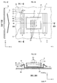
- FIG. 1A is a schematic view showing a radar device according to the first embodiment.
- FIG. 1B is a schematic cross-sectional view taken along the line IB-IB of FIG. 1A.
- FIG. 1C is a schematic cross-sectional view taken along the IC-IC line of FIG. 1A.
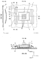
- FIG. 2A is a schematic view showing a radar device according to a first modification of the first embodiment.
- FIG. 2B is a schematic cross-sectional view taken along the line IIB-IIB of FIG. 2A.
- FIG. 2C is a schematic cross-sectional view taken along the line IIC-IIC of FIG. 2A.
- FIG. 3A is a schematic view showing a radar device according to a second modification of the first embodiment.
- FIG. 3A is a schematic view showing a radar device according to a second modification of the first embodiment.
- FIG. 3B is a schematic cross-sectional view taken along the line IIIB-IIIB of FIG. 3A.
- FIG. 3C is a schematic cross-sectional view taken along the line IIIC-IIIC of FIG. 3A.
- FIG. 4A is a schematic view showing a radar device according to a modified example 3 of the first embodiment.
- FIG. 4B is a schematic cross-sectional view taken along the line IVB-IVB of FIG. 4A.
- FIG. 4C is a schematic cross-sectional view taken along the line IVC-IVC of FIG. 4A.
- FIG. 5A is a schematic view showing a radar device according to a modified example 4 of the first embodiment.
- FIG. 5B is a schematic cross-sectional view taken along the line VB-VB of FIG. 5A.
- FIG. 5C is a schematic cross-sectional view taken along the line VC-VC of FIG. 5A.
- FIG. 6A is a schematic view showing a radar device according to a modified example 5 of the first embodiment.
- FIG. 6B is a schematic cross-sectional view taken along the line VIB-VIB of FIG. 6A.
- FIG. 6C is a schematic cross-sectional view taken along the line VIC-VIC of FIG. 6A.
- FIG. 7A is a schematic view showing a radar device according to a modification 6 of the first embodiment.
- FIG. 7B is a schematic cross-sectional view taken along the line VIIB-VIIB of FIG. 7A.
- FIG. 7C is a schematic cross-sectional view taken along the line VIIC-VIIC of FIG. 7A.
- FIG. 8A is a schematic view showing a radar device according to a modified example 7 of the first embodiment.
- FIG. 8B is a schematic cross-sectional view taken along the line VIIIB-VIIIB of FIG. 8A.
- FIG. 8C is a schematic cross-sectional view taken along the line VIIIC-VIIIC of FIG. 8A.
- FIG. 9A is a schematic view showing a radar device according to a modified example 8 of the first embodiment.
- FIG. 9B is a schematic cross-sectional view taken along the line IXB-IXB of FIG. 9A.
- 9C is a schematic cross-sectional view taken along the line IXC-IXC of FIG. 9A.
- FIG. 10A is a schematic view showing a radar device according to a modified example 9 of the first embodiment.
- FIG. 10B is a schematic cross-sectional view taken along the line XB-XB of FIG. 10A.
- FIG. 10C is a schematic cross-sectional view taken along the line XC-XC of FIG. 10A.
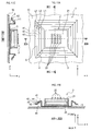
- FIG. 11A is a schematic view showing a radar device according to a modified example 10 of the first embodiment.
- FIG. 11B is a schematic cross-sectional view taken along the line XIB-XIB of FIG. 11A.
- FIG. 11C is a schematic cross-sectional view taken along the line XIC-XIC of FIG. 11A. It is a figure which shows the improvement effect of the azimuth detection error of the radar apparatus in 1st Embodiment.
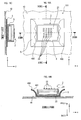
- FIG. 14A is a schematic view showing a radar device according to the second embodiment.
- FIG. 14B is a schematic cross-sectional view taken along the line XIVB-XIVB of FIG. 14A.
- FIG. 14C is a schematic cross-sectional view taken along the line XIVC-XIVC of FIG. 14A.
- FIG. 15A is a schematic view showing the radar device according to the first modification of the second embodiment.
- FIG. 15B is a schematic cross-sectional view taken along the line XVB-XVB of FIG. 15A.
- FIG. 15C is a schematic cross-sectional view taken along the line XVC-XVC of FIG. 15A.
- FIG. 16A is a schematic view showing a radar device according to a second embodiment of the second embodiment.
- FIG. 16B is a schematic cross-sectional view taken along the line XVIB-XVIB of FIG. 16A.
- FIG. 16C is a schematic cross-sectional view taken along the line XVIC-XVIC of FIG. 16A.
- FIG. 17A is a schematic view showing a radar device according to a modified example 3 of the second embodiment.
- FIG. 17B is a schematic cross-sectional view taken along the line XVIIB-XVIIB of FIG. 17A.
- FIG. 17C is a schematic cross-sectional view taken along the line XVIIC-XVIIC of FIG. 17A.
- FIG. 18A is a schematic view showing a radar device according to a modified example 4 of the second embodiment.
- FIG. 18B is a schematic cross-sectional view taken along the line XVIIIB-XVIIIB of FIG. 18A.
- FIG. 18C is a schematic cross-sectional view taken along the line XVIIIC-XVIIIC of FIG. 18A.
- FIG. 19A is a schematic view showing a radar device according to a modified example 5 of the second embodiment.
- FIG. 19B is a schematic cross-sectional view taken along the line XIXB-XIXB of FIG. 19A.
- FIG. 19C is a schematic cross-sectional view taken along the line XIXXC-XIXXC of FIG. 19A. It is a figure which shows the improvement effect of the azimuth detection error of the radar apparatus in 2nd Embodiment. It is a figure which shows the change of the antenna directivity of the radar apparatus in 2nd Embodiment.
- the radar device 1 of the first embodiment is mounted on a vehicle 10 and emits a radiated wave which is a radio wave having a predetermined frequency, and detects a reflected wave reflected by the radiated wave to detect an object. Is detected.
- the radar device 1 is installed inside the bumper of the vehicle 10, for example, and detects an object around the vehicle 10.
- the radar device 1 shown in FIG. 1 includes an antenna unit 2 and a radio wave reflecting unit 4.
- the antenna portion 2 includes a housing 3. Further, the radar device 1 may include a cover for protecting the antenna portion 2.
- the radar device 1 is a signal processing that processes a transmission / reception circuit that transmits / receives radiated waves and reflected waves via the antenna unit 2 and a reception signal received by the transmission / reception circuit in order to acquire information on surrounding objects. It has a part, etc.
- the antenna portion 2 includes a rectangular antenna substrate 21.
- a plurality of antenna elements 22 for transmitting and receiving radio waves are provided on one of both sides of the antenna substrate 21.
- the surface of the antenna substrate 21 on which the antenna element 22 is formed is referred to as an antenna surface 23.
- the antenna board 21 is housed in the housing 3 and fixed to the housing 3.
- the housing 3 is made of a metal material and acts as a ground.
- the antenna unit 2 does not necessarily have to include the housing 3, and may be directly installed in the vehicle 10.
- the long side direction of the antenna board 21 is the x-axis direction
- the short side direction is the y-axis direction
- the axial direction perpendicular to the antenna surface 23 of the antenna board 21 is the z-axis direction.
- the xyz three-dimensional coordinate axes will be described as appropriate.
- the positive direction of the z-axis is also referred to as a front
- the negative direction of the z-axis is also referred to as a rear.
- the side on which the radiated wave is radiated with the antenna surface 23 as a boundary is the front side of the antenna
- the opposite side is the rear side of the antenna.
- the x-axis direction is the direction in which the object exists (here, the azimuth in the horizontal direction), and is also hereinafter referred to as the azimuth detection direction.
- the plurality of antenna elements 22 are arranged side by side on the antenna substrate 21 along the x-axis direction and the y-axis direction in FIG. Then, among the plurality of antenna elements 22, one row of antenna elements 22 arranged along the y-axis direction form an array antenna, respectively. That is, the antenna unit 2 has a structure in which a plurality of array antennas are arranged along the x-axis direction.
- the y-axis direction coincides with the vehicle height direction
- the x-axis direction coincides with the horizontal direction
- the z-axis direction coincides with the center direction of the detection area.
- the detection area is an area within a range forming a predetermined solid angle from the center of the antenna surface 23.
- the radiated waves radiated outside the detection area are also referred to as unnecessary waves.
- One of the array antennas is used as a transmitting antenna, and the other array antennas are used as a receiving antenna.
- the mode of the transmitting antenna and the receiving antenna is not limited to this, and the arrangement of the array antenna used as the transmitting antenna and the array antenna used as the receiving antenna can be arbitrarily set.
- all array antennas may be used as a transmitting antenna and a receiving antenna.
- the radio wave reflecting unit 4 is made of a metal material.
- the radio wave reflecting unit 4 is designed so that unnecessary waves radiated from the antenna unit 2 and leaking outside the detection area are reflected by the radio wave reflecting unit 4.
- the radio wave reflecting units 4 are arranged one by one so as to sandwich the antenna unit 2 along the azimuth detection direction, that is, the x-axis direction in the drawing. Each of the two radio wave reflecting units 4 is directly installed on the installation surface 44 of the vehicle 10.
- the two radio wave reflecting units 4 have a symmetrical shape in the direction of azimuth detection.
- the configuration and shape of the radio wave reflecting unit 4 will be specifically described with a focus on one radio wave reflecting unit 4.
- the length of the radio wave reflecting unit 4 along the y-axis direction is formed longer than the width of the housing 3 in the y-axis direction.
- the radio wave reflecting unit 4 has a first metal surface 41, a second metal surface 42, and a third metal surface 43. These first metal surface 41, second metal surface 42, and third metal surface 43 function as reflecting surfaces that reflect unnecessary waves.
- the first metal surface 41, the second metal surface 42, and the third metal surface 43 have different heights in the z-axis direction and are formed in a three-step step shape. Specifically, the metal material extends forward from the installation surface 44, bends horizontally at 90 ° so as to be separated from the antenna portion 2, and extends to form the first metal surface 41.
- the metal material bends and extends 90 ° rearward from the first metal surface 41, and further bends and extends horizontally at 90 ° so as to be separated from the antenna portion 2, forming the second metal surface 42. Further, the metal material is bent and extended 90 ° rearward again from the second metal surface 42, and is further bent and extended horizontally at 90 ° so as to be separated from the antenna portion 2 to form the third metal surface 43.
- the first metal surface 41, the second metal surface 42, and the third metal surface 43 are not formed in order, such as the first metal surface 41 being formed first, but are integrally formed. Can be done.
- the third metal surface 43 which is the outermost metal surface of the first metal surface 41, the second metal surface 42, and the third metal surface 43, is formed from the center of the antenna portion 2. It is formed so that its height (that is, the height from the installation surface 44) gradually decreases toward the outer edge. Further, the first metal surface 41, the second metal surface 42, and the third metal surface 43 are formed so as to be substantially parallel to the antenna surface 23.
- the side wall 24 of the antenna portion 2 is along the direction of the line a1 passing through the upper end portion 25 of the side wall 24 in the orientation detection direction and substantially perpendicular to the installation surface 44 and the upper end portion 25 toward the installation surface 44.
- the range A is the range surrounded by the line a2 and the angle formed by the two lines (a1 and a2) is within about 60 °.
- the range B is defined as a range within 3 wavelengths ⁇ of the radio wave from the upper end 25 along the azimuth detection direction. All of the radio wave reflecting units 4 are arranged in the range S where the range A and the range B overlap. Since the range S has the same embodiment in other embodiments described later, description and illustration thereof will be omitted in the other embodiments.
- each metal surface of the radio wave reflecting portion 4 that is, the length from one end to the other end along the x-axis direction in the drawing is shorter than one wavelength of the radio wave.
- the length L1 of the first metal surface 41, the length L2 of the second metal surface 42, and the length L3 of the third metal surface 43 are all equal.
- the length L1 of the first metal surface 41, the length L2 of the second metal surface 42, and the length L3 of the third metal surface 43 may be different from each other.
- the height difference H1 and H2 of each metal surface of the radio wave reflecting portion 4 with respect to the installation surface 44 in the z-axis direction in the figure is m times 1/2 of the wavelength of the radio wave, where m is a positive integer. It is formed so as to take a value other than the value obtained.
- H1 is the difference between the height from the installation surface 44 to the first metal surface 41 and the height from the installation surface 44 to the second metal surface 42.
- H2 is the difference between the height from the installation surface 44 to the second metal surface 42 and the height from the installation surface 44 to the third metal surface 43.
- H1 and H2 are equal to each other. As long as the above conditions are satisfied, H1 and H2 may be different from each other.
- the radar device 1 is provided with a bracket 5 between the radar device 1 and the vehicle 10 on which the radar device 1 is installed.
- the bracket 5 is used to connect the radar device 1 and the vehicle 10.
- the bracket 5 is made of metal.
- the radar device 1 is attached to the vehicle 10 via the bracket 5.
- the bracket 5 may be attached to the vehicle 10 and the radar device 1 may be attached to the bracket 5, or the radar device 1 may be fixed to the vehicle 10 with the bracket 5 interposed between the bracket 5 and the vehicle 10. May be done.
- the radio wave reflecting portion 4 is integrally formed with the bracket 5, and can be formed by bending by press working or the like.
- the configurations of the first metal surface 41, the second metal surface 42, and the third metal surface 43 are the same as those in the first embodiment.
- the radio wave reflecting portion 4 in the present modification 2 is provided directly on the housing 3, and is formed by bending up a metal material from the contact portions between both side surfaces of the housing 3 in the x-axis direction and the vehicle 10.
- housing 3 and the radio wave reflecting unit 4 may be attached as separate parts or may be integrally formed.
- the configurations of the first metal surface 41, the second metal surface 42, and the third metal surface 43 are the same as those in the first embodiment.
- the first metal surface 41, the second metal surface 42, and the third metal surface 43 of the radio wave reflecting portion 4 in the third modification have different heights in the z-axis direction and are formed in a three-step step shape. ing. Specifically, the metal material extends forward from the installation surface 44, bends horizontally at 90 ° so as to be separated from the antenna portion 2, and extends to form the first metal surface 41. Further, the metal material bends and extends 90 ° forward from the first metal surface 41, and further bends and extends horizontally at 90 ° so as to be separated from the antenna portion 2, forming the second metal surface 42.
- the metal material bends and extends 90 ° forward again from the second metal surface 42, and further bends and extends horizontally at 90 ° so as to be separated from the antenna portion 2, forming the third metal surface 43.
- the outer edge of the third metal surface 43 which is the outermost metal surface of the first metal surface 41, the second metal surface 42, and the third metal surface 43 from the center of the antenna portion 2. It is formed so that its height gradually increases toward.
- Each metal surface of the radio wave reflecting portion 4 in the present modification 4 has a different height in the z-axis direction, and is formed so that the height is irregularly arranged.
- the radio wave reflecting portion 4 has a convex portion extending toward the front, and has a concave portion that is continuous with the convex portion and is recessed rearward.
- the metal surface of the radio wave reflecting portion 4 of the present modification 4 is formed horizontally in the x-axis direction.
- each metal surface of the radio wave reflecting portion 4 that is, the length from one end to the other end along the x-axis direction in the drawing is shorter than one wavelength of the radio wave.
- the difference in height of each metal surface of the radio wave reflecting portion 4 with respect to the installation surface 44 in the z-axis direction in the drawing is obtained by multiplying 1/2 of the wavelength of the radio wave by m, where m is a positive integer. It is formed to take a value other than the value.
- Each metal surface of the first metal surface 41, the second metal surface 42, and the third metal surface 43 in the present modification 5 is connected by an oblique surface. That is, the first metal surface 41, the second metal surface 42, and the third metal surface 43 are connected by surfaces that are non-parallel in the x-axis direction.
- a metal material extending diagonally forward from the installation surface 44 so as to be away from the antenna portion 2 bends horizontally in the x-axis direction and extends to form the first metal surface 41.
- the metal material bends and extends diagonally rearward from the first metal surface 41 so as to be separated from the antenna portion 2, and further bends and extends horizontally in the x-axis direction to form the second metal surface 42.
- the metal material bends and extends diagonally rearward from the second metal surface 42 so as to be separated from the antenna portion 2 again, and further bends and extends horizontally in the x-axis direction to form the third metal surface 43.
- the first metal surface 41, the second metal surface 42, and the third metal surface 43 in the present modification 6 are configured to have an angle with respect to the x-axis direction and are non-parallel.
- the metal material extending forward from the installation surface 44 bends diagonally forward so as to be separated from the antenna portion 2 and extends to form the first metal surface 41.
- the metal material bends and extends rearward from the first metal surface 41, and further bends and extends diagonally forward so as to be away from the antenna portion 2, forming the second metal surface 42.
- the metal material bends and extends rearward again from the second metal surface 42, and further bends and extends diagonally forward so as to separate from the antenna portion 2, forming the third metal surface 43.
- the first metal surface 41, the second metal surface 42, and the third metal surface 43 in the present modification 7 have heights with respect to the installation surface 44 along a direction substantially parallel to the installation surface 44 and substantially perpendicular to the orientation detection direction. Is configured to change. Specifically, the first metal surface 41, the second metal surface 42, and the third metal surface 43 of the radio wave reflecting portion 4 are configured to have a stepped shape along the y-axis direction.
- the first metal surface 41, the second metal surface 42, and the third metal surface 43 in the present modification 8 are substantially parallel to the installation surface 44 and along a direction substantially perpendicular to the orientation detection direction, as in the above modification 7.
- the height with respect to the installation surface 44 is configured to change.
- the first metal surface 41, the second metal surface 42, and the third metal surface 43 of the radio wave reflecting unit 4 are configured to have a mountain-fold shape along the y-axis direction.
- the first metal surface 41, the second metal surface 42, and the third metal surface 43 in the present modification 9 are substantially parallel to the installation surface 44 and substantially perpendicular to the orientation detection direction, as in the above modification 7 and 8. It is configured so that the height with respect to the installation surface 44 changes along the direction.
- the first metal surface 41, the second metal surface 42, and the third metal surface 43 of the radio wave reflecting portion 4 are configured to have a curved surface shape along the y-axis direction.
- the four radio wave reflecting units 4 are provided so as to face each other with the antenna unit 2 sandwiched in the x-axis direction, but in the present modification 10, the four radio wave reflecting units 4 are provided. Is provided. That is, the x-axis and y-axis directions in the drawing are both orientation detection directions, and one antenna portion 2 is provided opposite to each other in the x-axis and y-axis directions, and the outer periphery of the antenna portion 2 is provided. It is arranged so as to surround.
- the two radio wave reflecting units 4 in the y-axis direction have a symmetrical shape in the azimuth detection direction.
- the first metal surface 41, the second metal surface 42, and the third metal surface 43 of the radio wave reflecting portion 4 in the y-axis direction are formed so as to be substantially parallel to the y-axis in the drawing. Further, the difference in shape, width and height of each metal surface 41, 42, 43 with respect to the installation surface 44 is the same as that of each metal surface 41, 42, 43 of the radio wave reflecting portion 4 in the x-axis direction.
- the first metal surface 41, the second metal surface 42, and the third metal surface 43 of the radio wave reflecting portion 4 have different heights, so that the first metal surface 41, the second metal surface 42, and the third metal surface 43 In, the phase of each reflected wave is dispersed by reflecting each unnecessary wave. Then, the phase disturbance due to the interference of the reflected unnecessary wave with the radar radiated wave can be reduced. Therefore, the azimuth detection error of the radar can be reduced.
- FIG. 12 shows the results of measuring the detection azimuth accuracy with the radar device 1 provided with the radio wave reflecting unit 4 and the radar device with the radio wave reflecting unit omitted.
- the maximum error E1 of the azimuth accuracy is about 1.5 degrees in the radar device in which the radio wave reflecting unit is omitted, whereas the radar device 1 provided with the radio wave reflecting unit 4 has the azimuth accuracy.
- the maximum error E2 of was about 1 degree. Therefore, the detection orientation accuracy is improved.
- FIG. 13 shows the result of calculating the directivity of the gain by the simulation of the radar device 1 provided with the radio wave reflecting unit 4 and the radar device omitting the radio wave reflecting unit 4.
- the gain outside the detection area is significantly reduced as compared with the case where the radio wave reflecting unit is omitted.
- the radar device 1 of the present disclosure it is possible to reduce the object detection error of the radar without providing a radio wave absorbing element or the like. Therefore, it is possible to avoid an increase in the manufacturing cost by the amount that the radio wave absorbing element or the like is not provided, and thus to reduce the manufacturing cost.
- two radio wave reflecting units 400 are directly installed on the vehicle 10.
- the radio wave reflecting units 400 are arranged one by one so as to sandwich the antenna unit 2 along the x-axis direction in the drawing.
- the two radio wave reflecting units 400 have a symmetrical shape in the direction of azimuth detection.
- the configuration and shape of the radio wave reflecting unit 400 will be specifically described with a focus on one radio wave reflecting unit 400.
- the radio wave reflecting unit 400 has a curved surface portion 401.
- the curved surface portion 401 is curved so that the height of the radar device 101 with respect to the installation surface 44 gradually changes. Specifically, the curved surface portion 401 is curved so that the height in the z-axis direction increases as the distance from the antenna portion 2 increases. Then, the curved surface portion 401 functions as a reflecting surface.
- the radar device 101 includes a bracket 5 between the radar device 101 and the vehicle 10 on which the radar device 101 is installed.
- the bracket 5 is used to connect the radar device 101 and the vehicle 10.
- the bracket 5 is made of metal.
- the radar device 101 is attached to the vehicle 10 via the bracket 5.
- the bracket 5 may be attached to the vehicle 10, and the radar device 101 may be attached to the bracket 5, or the radar device 101 is fixed to the vehicle 10 with the bracket 5 interposed between the bracket 5 and the vehicle 10. You may.
- the radio wave reflecting portion 400 is integrally formed with the bracket 5, and is formed by being bent by press working or the like.
- the configuration of the curved surface portion 401 is the same as that of the second embodiment.
- the radio wave reflecting portion 400 in the second modification is provided directly on the housing 3, and is formed by bending up a metal material from the contact portions between both side surfaces of the housing 3 in the x-axis direction and the vehicle 10.
- housing 3 and the radio wave reflecting unit 400 may be attached as separate parts or may be integrally formed.
- the configuration of the curved surface portion 401 is the same as that of the second embodiment.
- the curved surface portion 401 of the radio wave reflecting portion 400 in the present modification 4 is configured so that the height with respect to the installation surface 44 gradually changes along a direction substantially parallel to the installation surface 44 and substantially perpendicular to the orientation detection direction. .. Specifically, the curved surface portion 401 of the radio wave reflecting portion 400 is configured to be hemispherical along the y-axis direction.
- the curved surface portion 401 of the radio wave reflecting portion 400 in the present modification 4 is configured so that the height with respect to the installation surface 44 gradually changes along a direction substantially parallel to the installation surface 44 and substantially perpendicular to the orientation detection direction. .. Specifically, the curved surface portion 401 of the radio wave reflecting portion 400 is configured to have a shape in which three hemispheres are connected along the y-axis direction so that a part of each outer surface overlaps.
- two radio wave reflecting units 400 are provided so as to face each other with the antenna unit 2 sandwiched in the x-axis direction, but in the present modification 5, the four radio wave reflecting units 400 are provided.
- the four radio wave reflecting units 400 are provided.
- one antenna portion 2 is provided opposite to each other in the x-axis and y-axis directions, and the antenna portions 2 are arranged so as to surround the outer circumference of the antenna portion 2.
- the two radio wave reflecting units 400 in the y-axis direction have symmetrical shapes in the azimuth detection direction.
- each curved surface portion 401 in the y-axis direction is the same as those of the curved surface portion 401 in the x-axis direction.
- each reflected wave is diffused, and the phase disturbance due to the interference of the reflected unnecessary waves with the radar radiation wave can be reduced. Therefore, the azimuth detection error of the radar can be reduced.
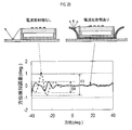
- FIG. 20 shows the results of measuring the detection azimuth accuracy with the radar device 101 provided with the radio wave reflecting unit 400 and the radar device with the radio wave reflecting unit omitted.
- the maximum error E3 of the azimuth accuracy is about 1 degree in the radar device in which the radio wave reflecting unit is omitted, whereas the radar device 101 provided with the radio wave reflecting unit 400 has the maximum azimuth accuracy.
- the error E4 was about 0.5 degrees. Therefore, the detection orientation accuracy is improved.
- FIG. 21 shows the result of calculating the directivity of the gain by simulation with the radar device 101 provided with the radio wave reflecting unit 400 and the radar device with the radio wave reflecting unit omitted.
- the gain outside the detection area is significantly reduced as compared with the case where the radio wave reflecting unit is omitted.
- the object detection error of the radar can be reduced without providing a radio wave absorbing element or the like. Therefore, it is possible to avoid an increase in manufacturing cost as much as it is not necessary to provide a radio wave absorbing element or the like.
- the number of metal surfaces in the radio wave reflecting unit is three, but the number of metal surfaces in the radio wave reflecting unit is not limited to three.
- the installation location of the radio wave reflecting unit does not necessarily have to be in the orientation detection direction, and the radio wave reflecting unit does not necessarily have to be arranged at a position opposite to each other.
- a radar device having a radio wave reflecting unit has been described, but the present disclosure may be, for example, a single bracket provided with a radio wave reflecting unit. As a result, the bracket alone can produce the same effect as the above-mentioned effect.
- a plurality of functions possessed by one component in the above embodiment may be realized by a plurality of components, or one function possessed by one component may be realized by a plurality of components. .. Further, a plurality of functions possessed by the plurality of components may be realized by one component, or one function realized by the plurality of components may be realized by one component. Further, a part of the configuration of the above embodiment may be omitted. In addition, at least a part of the configuration of the above embodiment may be added or replaced with the configuration of the other above embodiment.
Landscapes
- Engineering & Computer Science (AREA)
- Radar, Positioning & Navigation (AREA)
- Remote Sensing (AREA)
- Physics & Mathematics (AREA)
- Computer Networks & Wireless Communication (AREA)
- General Physics & Mathematics (AREA)
- Electromagnetism (AREA)
- Computer Security & Cryptography (AREA)
- Radar Systems Or Details Thereof (AREA)
- Aerials With Secondary Devices (AREA)
Priority Applications (3)
| Application Number | Priority Date | Filing Date | Title |
|---|---|---|---|
| DE112020001806.7T DE112020001806T5 (de) | 2019-04-08 | 2020-04-08 | Radarvorrichtung und halterung für radarvorrichtung |
| CN202080026869.7A CN113661610B (zh) | 2019-04-08 | 2020-04-08 | 雷达装置以及雷达装置用托架 |
| US17/495,261 US12276748B2 (en) | 2019-04-08 | 2021-10-06 | Radar device and bracket for radar device |
Applications Claiming Priority (2)
| Application Number | Priority Date | Filing Date | Title |
|---|---|---|---|
| JP2019-073423 | 2019-04-08 | ||
| JP2019073423A JP7132167B2 (ja) | 2019-04-08 | 2019-04-08 | レーダ装置及びレーダ装置用ブラケット |
Related Child Applications (1)
| Application Number | Title | Priority Date | Filing Date |
|---|---|---|---|
| US17/495,261 Continuation US12276748B2 (en) | 2019-04-08 | 2021-10-06 | Radar device and bracket for radar device |
Publications (1)
| Publication Number | Publication Date |
|---|---|
| WO2020209306A1 true WO2020209306A1 (ja) | 2020-10-15 |
Family
ID=72750694
Family Applications (1)
| Application Number | Title | Priority Date | Filing Date |
|---|---|---|---|
| PCT/JP2020/015868 Ceased WO2020209306A1 (ja) | 2019-04-08 | 2020-04-08 | レーダ装置及びレーダ装置用ブラケット |
Country Status (5)
| Country | Link |
|---|---|
| US (1) | US12276748B2 (https=) |
| JP (1) | JP7132167B2 (https=) |
| CN (1) | CN113661610B (https=) |
| DE (1) | DE112020001806T5 (https=) |
| WO (1) | WO2020209306A1 (https=) |
Cited By (1)
| Publication number | Priority date | Publication date | Assignee | Title |
|---|---|---|---|---|
| FR3137341A1 (fr) * | 2022-06-30 | 2024-01-05 | Psa Automobiles Sa | Dispositif de détection à cibles fantômes réduites, pour un véhicule terrestre |
Families Citing this family (3)
| Publication number | Priority date | Publication date | Assignee | Title |
|---|---|---|---|---|
| JP7495096B2 (ja) * | 2020-01-21 | 2024-06-04 | Necプラットフォームズ株式会社 | アンテナ装置 |
| DE102022132832A1 (de) * | 2022-12-09 | 2024-06-20 | Friedrich-Alexander-Universität Erlangen-Nürnberg, Körperschaft des öffentlichen Rechts | Antennenarray |
| CN116666951A (zh) * | 2023-07-03 | 2023-08-29 | 深圳市华信天线技术有限公司 | 带引向赋形阵列天线 |
Citations (6)
| Publication number | Priority date | Publication date | Assignee | Title |
|---|---|---|---|---|
| JPH08102608A (ja) * | 1994-09-30 | 1996-04-16 | Nec Corp | アンテナ装置 |
| JP2004258044A (ja) * | 2004-04-12 | 2004-09-16 | Hitachi Ltd | ミリ波レーダ |
| JP2004312696A (ja) * | 2003-03-24 | 2004-11-04 | Hitachi Ltd | ミリ波レーダおよびその製造方法 |
| DE102009042285A1 (de) * | 2009-09-22 | 2011-03-31 | Volkswagen Ag | Schirmung von Radarsensorik |
| US20160268693A1 (en) * | 2015-03-12 | 2016-09-15 | Autoliv Asp, Inc. | Apparatus and method for mitigating multipath effects and improving absorption of an automotive radar module |
| JP2017058196A (ja) * | 2015-09-15 | 2017-03-23 | 古河電気工業株式会社 | レーダ装置を取り付けた構造体、レーダ装置の取り付け方法、および、ブラケット |
Family Cites Families (11)
| Publication number | Priority date | Publication date | Assignee | Title |
|---|---|---|---|---|
| JP2004312966A (ja) * | 2003-04-02 | 2004-11-04 | Hitachi Lighting Ltd | インバータ装置 |
| US7812767B2 (en) * | 2004-09-07 | 2010-10-12 | Nippon Telegraph And Telephone Corporation | Antenna device, array antenna device using the antenna device, module, module array and package module |
| JP2006184130A (ja) * | 2004-12-27 | 2006-07-13 | Tdk Corp | レーダー装置 |
| JP2010154182A (ja) * | 2008-12-25 | 2010-07-08 | Koito Mfg Co Ltd | 車載レーダ装置 |
| GB201016748D0 (en) * | 2010-10-05 | 2010-11-17 | Univ Leeds | Reflective substrate |
| DE102011122346A1 (de) | 2011-12-23 | 2013-06-27 | Valeo Schalter Und Sensoren Gmbh | Radareinrichtung für ein Kraftfahrzeug, Halter für ein Radargerät und Verfahren zum Herstellen eines Absorptionselements für ein Radargerät |
| US9608330B2 (en) * | 2012-02-07 | 2017-03-28 | Los Alamos National Laboratory | Superluminal antenna |
| US10101444B2 (en) * | 2014-09-11 | 2018-10-16 | Cpg Technologies, Llc | Remote surface sensing using guided surface wave modes on lossy media |
| CN107359417B (zh) * | 2017-06-21 | 2019-07-12 | 西安空间无线电技术研究所 | 一种新型低剖面电扫描波束反射阵天线 |
| JP2019073423A (ja) | 2017-10-19 | 2019-05-16 | セントラル硝子株式会社 | 車両の窓ガラス用曲面合わせガラス |
| JP2019097118A (ja) * | 2017-11-27 | 2019-06-20 | パナソニックIpマネジメント株式会社 | アンテナ装置 |
-
2019
- 2019-04-08 JP JP2019073423A patent/JP7132167B2/ja active Active
-
2020
- 2020-04-08 DE DE112020001806.7T patent/DE112020001806T5/de active Pending
- 2020-04-08 CN CN202080026869.7A patent/CN113661610B/zh active Active
- 2020-04-08 WO PCT/JP2020/015868 patent/WO2020209306A1/ja not_active Ceased
-
2021
- 2021-10-06 US US17/495,261 patent/US12276748B2/en active Active
Patent Citations (6)
| Publication number | Priority date | Publication date | Assignee | Title |
|---|---|---|---|---|
| JPH08102608A (ja) * | 1994-09-30 | 1996-04-16 | Nec Corp | アンテナ装置 |
| JP2004312696A (ja) * | 2003-03-24 | 2004-11-04 | Hitachi Ltd | ミリ波レーダおよびその製造方法 |
| JP2004258044A (ja) * | 2004-04-12 | 2004-09-16 | Hitachi Ltd | ミリ波レーダ |
| DE102009042285A1 (de) * | 2009-09-22 | 2011-03-31 | Volkswagen Ag | Schirmung von Radarsensorik |
| US20160268693A1 (en) * | 2015-03-12 | 2016-09-15 | Autoliv Asp, Inc. | Apparatus and method for mitigating multipath effects and improving absorption of an automotive radar module |
| JP2017058196A (ja) * | 2015-09-15 | 2017-03-23 | 古河電気工業株式会社 | レーダ装置を取り付けた構造体、レーダ装置の取り付け方法、および、ブラケット |
Cited By (1)
| Publication number | Priority date | Publication date | Assignee | Title |
|---|---|---|---|---|
| FR3137341A1 (fr) * | 2022-06-30 | 2024-01-05 | Psa Automobiles Sa | Dispositif de détection à cibles fantômes réduites, pour un véhicule terrestre |
Also Published As
| Publication number | Publication date |
|---|---|
| US12276748B2 (en) | 2025-04-15 |
| JP7132167B2 (ja) | 2022-09-06 |
| DE112020001806T5 (de) | 2022-01-20 |
| JP2020173105A (ja) | 2020-10-22 |
| CN113661610B (zh) | 2024-08-09 |
| CN113661610A (zh) | 2021-11-16 |
| US20220026522A1 (en) | 2022-01-27 |
Similar Documents
| Publication | Publication Date | Title |
|---|---|---|
| JP6510439B2 (ja) | アンテナ装置 | |
| WO2020209306A1 (ja) | レーダ装置及びレーダ装置用ブラケット | |
| JP6643203B2 (ja) | レーダ装置 | |
| JP5603636B2 (ja) | レドーム、アンテナ装置、およびレーダ装置 | |
| JP2019158592A (ja) | アンテナ装置 | |
| CN110582706B (zh) | 雷达装置 | |
| JP7099861B2 (ja) | レーダ装置 | |
| US12603423B2 (en) | Radome design | |
| JP6326920B2 (ja) | レーダ装置 | |
| US11056766B2 (en) | Antenna apparatus | |
| JP2007235287A (ja) | 車載用電波レーダ装置 | |
| EP3920329B1 (en) | Antenna device | |
| US12300881B2 (en) | Radar device | |
| EP4024611A1 (en) | Radar device | |
| JP2015190810A (ja) | レーダ装置およびレーダ方法 | |
| EP3923020A1 (en) | Radar device | |
| JP2019200121A (ja) | レーダシステム、および車両 | |
| US11639993B2 (en) | Radar apparatus | |
| US20240272274A1 (en) | Radar device | |
| JP2022027059A (ja) | レーダ装置 | |
| WO2024053229A1 (ja) | レーダ装置用カバー | |
| KR20150055280A (ko) | 캐릭터 라인에 의해 발생되는 사이드 로브를 감쇄시키기 위한 구조 시스템 |
Legal Events
| Date | Code | Title | Description |
|---|---|---|---|
| 121 | Ep: the epo has been informed by wipo that ep was designated in this application |
Ref document number: 20787321 Country of ref document: EP Kind code of ref document: A1 |
|
| 122 | Ep: pct application non-entry in european phase |
Ref document number: 20787321 Country of ref document: EP Kind code of ref document: A1 |