WO2020209146A1 - タービンおよび過給機 - Google Patents
タービンおよび過給機 Download PDFInfo
- Publication number
- WO2020209146A1 WO2020209146A1 PCT/JP2020/014893 JP2020014893W WO2020209146A1 WO 2020209146 A1 WO2020209146 A1 WO 2020209146A1 JP 2020014893 W JP2020014893 W JP 2020014893W WO 2020209146 A1 WO2020209146 A1 WO 2020209146A1
- Authority
- WO
- WIPO (PCT)
- Prior art keywords
- flow path
- turbine
- turbine scroll
- scroll flow
- wastegate
- Prior art date
- Legal status (The legal status is an assumption and is not a legal conclusion. Google has not performed a legal analysis and makes no representation as to the accuracy of the status listed.)
- Ceased
Links
Images




Classifications
-
- F—MECHANICAL ENGINEERING; LIGHTING; HEATING; WEAPONS; BLASTING
- F02—COMBUSTION ENGINES; HOT-GAS OR COMBUSTION-PRODUCT ENGINE PLANTS
- F02B—INTERNAL-COMBUSTION PISTON ENGINES; COMBUSTION ENGINES IN GENERAL
- F02B37/00—Engines characterised by provision of pumps driven at least for part of the time by exhaust
- F02B37/02—Gas passages between engine outlet and pump drive, e.g. reservoirs
- F02B37/025—Multiple scrolls or multiple gas passages guiding the gas to the pump drive
-
- F—MECHANICAL ENGINEERING; LIGHTING; HEATING; WEAPONS; BLASTING
- F01—MACHINES OR ENGINES IN GENERAL; ENGINE PLANTS IN GENERAL; STEAM ENGINES
- F01D—NON-POSITIVE DISPLACEMENT MACHINES OR ENGINES, e.g. STEAM TURBINES
- F01D17/00—Regulating or controlling by varying flow
- F01D17/10—Final actuators
- F01D17/105—Final actuators by passing part of the fluid
-
- F—MECHANICAL ENGINEERING; LIGHTING; HEATING; WEAPONS; BLASTING
- F01—MACHINES OR ENGINES IN GENERAL; ENGINE PLANTS IN GENERAL; STEAM ENGINES
- F01D—NON-POSITIVE DISPLACEMENT MACHINES OR ENGINES, e.g. STEAM TURBINES
- F01D9/00—Stators
- F01D9/02—Nozzles; Nozzle boxes; Stator blades; Guide conduits, e.g. individual nozzles
- F01D9/026—Scrolls for radial machines or engines
-
- F—MECHANICAL ENGINEERING; LIGHTING; HEATING; WEAPONS; BLASTING
- F02—COMBUSTION ENGINES; HOT-GAS OR COMBUSTION-PRODUCT ENGINE PLANTS
- F02B—INTERNAL-COMBUSTION PISTON ENGINES; COMBUSTION ENGINES IN GENERAL
- F02B37/00—Engines characterised by provision of pumps driven at least for part of the time by exhaust
- F02B37/12—Control of the pumps
- F02B37/18—Control of the pumps by bypassing exhaust from the inlet to the outlet of turbine or to the atmosphere
-
- F—MECHANICAL ENGINEERING; LIGHTING; HEATING; WEAPONS; BLASTING
- F02—COMBUSTION ENGINES; HOT-GAS OR COMBUSTION-PRODUCT ENGINE PLANTS
- F02B—INTERNAL-COMBUSTION PISTON ENGINES; COMBUSTION ENGINES IN GENERAL
- F02B39/00—Component parts, details, or accessories relating to, driven charging or scavenging pumps, not provided for in groups F02B33/00 - F02B37/00
-
- F—MECHANICAL ENGINEERING; LIGHTING; HEATING; WEAPONS; BLASTING
- F02—COMBUSTION ENGINES; HOT-GAS OR COMBUSTION-PRODUCT ENGINE PLANTS
- F02C—GAS-TURBINE PLANTS; AIR INTAKES FOR JET-PROPULSION PLANTS; CONTROLLING FUEL SUPPLY IN AIR-BREATHING JET-PROPULSION PLANTS
- F02C6/00—Plural gas-turbine plants; Combinations of gas-turbine plants with other apparatus; Adaptations of gas-turbine plants for special use
- F02C6/04—Gas-turbine plants providing heated or pressurised working fluid for other apparatus, e.g. without mechanical power output
- F02C6/10—Gas-turbine plants providing heated or pressurised working fluid for other apparatus, e.g. without mechanical power output supplying working fluid to a user, e.g. a chemical process, which returns working fluid to a turbine of the plant
- F02C6/12—Turbochargers, i.e. plants for augmenting mechanical power output of internal-combustion piston engines by increase of charge pressure
-
- F—MECHANICAL ENGINEERING; LIGHTING; HEATING; WEAPONS; BLASTING
- F05—INDEXING SCHEMES RELATING TO ENGINES OR PUMPS IN VARIOUS SUBCLASSES OF CLASSES F01-F04
- F05D—INDEXING SCHEME FOR ASPECTS RELATING TO NON-POSITIVE-DISPLACEMENT MACHINES OR ENGINES, GAS-TURBINES OR JET-PROPULSION PLANTS
- F05D2220/00—Application
- F05D2220/40—Application in turbochargers
-
- F—MECHANICAL ENGINEERING; LIGHTING; HEATING; WEAPONS; BLASTING
- F05—INDEXING SCHEMES RELATING TO ENGINES OR PUMPS IN VARIOUS SUBCLASSES OF CLASSES F01-F04
- F05D—INDEXING SCHEME FOR ASPECTS RELATING TO NON-POSITIVE-DISPLACEMENT MACHINES OR ENGINES, GAS-TURBINES OR JET-PROPULSION PLANTS
- F05D2260/00—Function
- F05D2260/60—Fluid transfer
- F05D2260/606—Bypassing the fluid
-
- Y—GENERAL TAGGING OF NEW TECHNOLOGICAL DEVELOPMENTS; GENERAL TAGGING OF CROSS-SECTIONAL TECHNOLOGIES SPANNING OVER SEVERAL SECTIONS OF THE IPC; TECHNICAL SUBJECTS COVERED BY FORMER USPC CROSS-REFERENCE ART COLLECTIONS [XRACs] AND DIGESTS
- Y02—TECHNOLOGIES OR APPLICATIONS FOR MITIGATION OR ADAPTATION AGAINST CLIMATE CHANGE
- Y02T—CLIMATE CHANGE MITIGATION TECHNOLOGIES RELATED TO TRANSPORTATION
- Y02T10/00—Road transport of goods or passengers
- Y02T10/10—Internal combustion engine [ICE] based vehicles
- Y02T10/12—Improving ICE efficiencies
Definitions
- Some turbines installed in turbochargers, etc. are provided with two turbine scroll flow paths.
- a wastegate flow path that opens on the inner wall surface of two turbine scroll flow paths is formed. If the flow rate of the exhaust gas is too high, the exhaust gas flows around the turbine impeller through the wastegate flow path. As a result, over-rotation of the turbocharger is suppressed.
- a wastegate flow path is open on the inner wall surface of the turbine scroll flow path. Even if the wastegate flow path is closed, the flow of exhaust gas is disturbed due to the influence of the opening of the wastegate flow path. Therefore, a pressure loss of exhaust gas occurs.
- An object of the present disclosure is to provide a turbine and a supercharger capable of suppressing a pressure loss of exhaust gas.
- the turbine according to one aspect of the present disclosure communicates with a turbine impeller housed in the accommodation space, two turbine scroll flow paths connected to the accommodation space, and one turbine scroll flow path.
- a first wastegate flow path that is separated from the other turbine scroll flow path and a valve that opens and closes the first wastegate flow path are provided.
- a second wastegate flow path may be provided.
- the tongue portions provided downstream of each of the two turbine scroll flow paths may have different positions in the rotational direction of the turbine impeller.
- the tongue portions provided downstream of each of the two turbine scroll flow paths may have the same positions in the rotational direction of the turbine impellers.
- One turbine scroll flow path may have a smaller flow path cross-sectional area than the other turbine scroll flow path.
- a second upper flow path that is located upstream of the turbine, communicates with one turbine scroll flow path, and opens the EGR flow path may be provided.
- the supercharger according to one aspect of the present disclosure includes the above turbine.
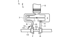
- FIG. 1 is a diagram showing an outline of an engine and an intake / exhaust mechanism of an engine.
- FIG. 2 is a schematic cross-sectional view of the turbocharger.
- FIG. 3 is a sectional view taken along line III-III of FIG.
- FIG. 4 is an IV arrow view of FIG.
- FIG. 5 is an extracted view of the broken line portion of FIG.
- FIG. 6 is a diagram for explaining valve opening.
- FIG. 7 is a diagram for explaining a modified example.
- FIG. 8 is a cross-sectional view of a position corresponding to FIG. 5 in the modified example.
- FIG. 1 is a diagram showing an outline of an engine 1 and an intake / exhaust mechanism 2 of the engine 1.
- the intake / exhaust mechanism 2 has a supercharger TC.
- the compressor C of the turbocharger TC is provided in the intake flow path 3.
- a throttle valve 4 and a surge tank 5 are provided on the downstream side of the compressor C in the intake flow path 3.
- the engine 1 has a plurality of cylinders 6. Intake is supplied from the surge tank 5 to each cylinder 6.
- the exhaust gas discharged from some of the cylinders 6 merges at the first collecting portion 7.
- the first upper flow path 8 of the turbine T is connected to the first collecting portion 7. Exhaust gas is supplied to the turbine T of the turbocharger TC through the first collecting portion 7 and the first upper flow path 8.
- the exhaust gas discharged from the remaining cylinders 6 merges at the second collecting portion 9.
- the second upper flow path 10 of the turbine T is connected to the second collecting portion 9. Exhaust gas is supplied to the turbine T of the turbocharger TC through the second collecting portion 9 and the second upper flow path 10.
- the flow path width from the cylinder 6 to the second gathering portion 9 is narrower than the flow path width from the cylinder 6 to the first gathering portion 7.
- the flow path width from the cylinder 6 to the second gathering portion 9 may be the same as the flow path width from the cylinder 6 to the first gathering portion 7.
- the flow path width of the second gathering portion 9 is narrower than the flow path width of the first gathering portion 7.
- the flow path width of the second gathering portion 9 may be the same as the flow path width of the first gathering portion 7.
- the flow path width of the second upper flow path 10 is narrower than the flow path width of the first upper flow path 8.
- the flow path width of the second upper flow path 10 may be the same as the flow path width of the first upper flow path 8.
- the EGR valve 12 is provided in the EGR flow path 11. When the EGR valve 12 is opened, exhaust gas flows from the second collecting portion 9 to the surge tank 5.
- the opening degree of the EGR valve 12 may be arbitrarily controllable between fully open and fully closed.
- the intake / exhaust mechanism 2 is provided with HP-EGR (High Pressure-Exhaust Gas Recirculation).
- the turbine T is provided with an exhaust pipe 13 (downstream side flow path) and a wastegate flow path 14. Exhaust gas is discharged from the turbine T through the exhaust pipe 13.
- the wastegate flow path 14 (second wastegate flow path) is connected to the first upper flow path 8 and the exhaust pipe 13.
- An on-off valve 15 is provided in the wastegate flow path 14.
- the wastegate flow path 14 is opened and closed by the on-off valve 15. The opening degree of the on-off valve 15 may be arbitrarily controllable between fully open and fully closed.
- FIG. 2 is a schematic cross-sectional view of the turbocharger TC.
- the supercharger TC includes a supercharger main body 21.
- the supercharger main body 21 includes a bearing housing 22.
- the turbine housing 24 is connected to the left side of the bearing housing 22 by the fastening mechanism 23.
- the fastening mechanism 23 is composed of, for example, a G coupling.
- the bearing housing 22 and the turbine housing 24 are band-fastened by the fastening mechanism 23.
- the compressor housing 26 is connected to the right side of the bearing housing 22 by a fastening bolt 25.
- the fastening bolt 25 side functions as the turbine T.
- the compressor housing 26 side functions as the compressor C.
- a bearing hole 22a is formed in the bearing housing 22.
- the bearing hole 22a penetrates the supercharger TC in the left-right direction.
- the bearing 27 is provided in the bearing hole 22a.
- a fully floating bearing is shown as an example of the bearing 27.
- the bearing 27 may be another radial bearing such as a semi-floating bearing or a rolling bearing.
- the shaft 28 is rotatably supported by the bearing 27.
- a turbine impeller 29 is provided at the left end of the shaft 28.
- the turbine impeller 29 is rotatably accommodated in the accommodation space S formed in the turbine housing 24.
- a compressor impeller 30 is provided at the right end of the shaft 28.
- the compressor impeller 30 is rotatably housed in the compressor housing 26.
- An intake port 31 is formed in the compressor housing 26.
- the intake port 31 opens on the right side of the turbocharger TC.
- the upstream side of the compressor C in the above intake flow path 3 is connected to the intake port 31.
- the diffuser flow path 32 boosts air.
- the diffuser flow path 32 is formed in an annular shape from the inside to the outside in the radial direction (hereinafter, simply referred to as the radial direction) of the shaft 28.
- the radial inside of the diffuser flow path 32 communicates with the intake port 31 via the compressor impeller 30.
- a compressor scroll flow path 33 is formed inside the compressor housing 26.
- the compressor scroll flow path 33 has an annular shape.
- the compressor scroll flow path 33 is located, for example, outside the diffuser flow path 32 in the radial direction of the shaft 28.
- the downstream side of the compressor C is connected to the compressor scroll flow path 33.
- the compressor scroll flow path 33 communicates with the diffuser flow path 32.
- a discharge flow path 34 (downstream side flow path) is formed in the turbine housing 24.
- the discharge flow path 34 opens on the left side of the turbocharger TC.
- the exhaust pipe 13 is connected to the discharge flow path 34.
- the discharge flow path 34 communicates with the accommodation space S.
- the discharge flow path 34 extends from the turbine impeller 29 in the rotation axis direction (hereinafter, simply referred to as the rotation axis direction) of the turbine impeller 29.
- the turbine housing 24 is provided with a first turbine scroll flow path 35 (the other turbine scroll flow path) and a second turbine scroll flow path 36 (one turbine scroll flow path).
- the first turbine scroll flow path 35 and the second turbine scroll flow path 36 are located outside the accommodation space S in the radial direction and are connected to the accommodation space S.
- the first turbine scroll flow path 35 communicates with the first upper flow path 8.
- the second turbine scroll flow path 36 communicates with the second upper flow path 10. Exhaust gas guided from the first upper flow path 8 and the second upper flow path 10 to the first turbine scroll flow path 35 and the second turbine scroll flow path 36 is guided to the discharge flow path 34 via the blades of the turbine impeller 29. Be taken.
- the turbine impeller 29 rotates in the exhaust gas distribution process.
- the second turbine scroll flow path 36 has a smaller flow path cross-sectional area than the first turbine scroll flow path 35.
- the flow path cross-sectional area is, for example, as shown in FIG. 2, the area in the cross section of the turbine impeller 29 in a plane including the rotation axis.
- the second turbine scroll flow path 36 is located on the left side (the side separated from the bearing housing 22 or the bearing 27) in FIG. 2 with respect to the first turbine scroll flow path 35.
- the first turbine scroll flow path 35 extends to the outside in the radial direction with respect to the second turbine scroll flow path 36.
- the first turbine scroll flow path 35 may extend outward in the radial direction to approximately the same position as the second turbine scroll flow path 36.
- the second turbine scroll flow path 36 may extend to the outside in the radial direction with respect to the first turbine scroll flow path 35. Even in this case, the second turbine scroll is due to a difference in shape such that the length of the first turbine scroll flow path 35 in the rotation axis direction is longer than the length of the second turbine scroll flow path 36 in the rotation axis direction.
- the flow path 36 has a smaller flow path cross-sectional area than the first turbine scroll flow path 35.
- FIG. 3 is a sectional view taken along line III-III of FIG.
- FIG. 3 shows a view in which the turbine housing 24 is cut in a plane perpendicular to the axial direction of the shaft 28 and passing through the first turbine scroll flow path 35.
- the turbine impeller 29 is represented by a circle.
- a first gas inflow port 37 is formed in the turbine housing 24.
- the first gas inflow port 37 opens to the outside of the turbine housing 24.
- the first upper flow path 8 is connected to the first gas inflow port 37.
- a first introduction path 38 is formed between the first gas inflow port 37 and the first turbine scroll flow path 35.
- the first introduction path 38 extends substantially in a straight line.
- the first gas inflow port 37 communicates with the first turbine scroll flow path 35 via the first introduction path 38.
- the second turbine scroll flow path 36 is located on the back side of the paper in FIG. 3 with respect to the first turbine scroll flow path 35.
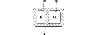
- FIG. 4 is an IV arrow view of FIG.
- the second gas inflow port 39 is arranged side by side with the first gas inflow port 37.
- the second upper flow path 10 is connected to the second gas inflow port 39.
- the second gas inflow port 39 is smaller than the first gas inflow port 37.
- the second gas inflow port 39 may have approximately the same size as the first gas inflow port 37.
- a second introduction path 40 is formed between the second gas inflow port 39 and the second turbine scroll flow path 36.
- the flow path cross-sectional area of the second introduction path 40 is smaller than the flow path cross-sectional area of the first introduction path 38.
- the flow path cross-sectional area of the second introduction path 40 may be approximately equal to the flow path cross-sectional area of the first introduction path 38.
- the second gas inflow port 39 communicates with the second turbine scroll flow path 36 via the second introduction path 40.
- the partition wall 41 partitions the first turbine scroll flow path 35 and the second turbine scroll flow path 36, the first gas inflow port 37 and the second gas inflow port 39, and the first introduction path 38 and the second introduction path 40, respectively ( See FIGS. 2, 3, and 4).
- the tongue portion 42 is provided in the downstream portion 35a of the first turbine scroll flow path 35.
- the tongue portion 42 partitions the downstream portion 35a and the upstream portion 35b of the first turbine scroll flow path 35.
- the tongue portion 43 is formed on the back side of the paper surface in FIG. 3 with respect to the tongue portion 42.
- the tongue portion 43 is provided in the downstream portion of the second turbine scroll flow path 36, and partitions the downstream portion and the upstream portion.
- the turbine T is a so-called twin scroll turbine.
- FIG. 5 is an extracted view of the broken line portion of FIG.
- the cross section shown in FIG. 5 differs from the cross section shown in FIG. 2 in the position of the turbine impeller 29 in the rotational direction.
- a wastegate flow path 44 (first wastegate flow path) is formed in the turbine housing 24.
- the wastegate flow path 44 opens into the second turbine scroll flow path 36 and the discharge flow path 34.
- the wastegate flow path 44 communicates the second turbine scroll flow path 36 and the discharge flow path 34 without passing through the accommodation space S (turbine impeller 29).
- the wastegate flow path 44 has a valve chamber 44a, a first through hole 44b, and a second through hole 44c.
- the valve chamber 44a is located outside the turbine housing 24 in the radial direction of the discharge flow path 34.
- the first through hole 44b penetrates the turbine housing 24 from the valve chamber 44a to the second turbine scroll flow path 36.
- the first through hole 44b extends in the direction of the rotation axis, for example.
- the second through hole 44c penetrates the turbine housing 24 from the valve chamber 44a to the discharge flow path 34.
- the second through hole 44c extends, for example, in the radial direction.
- a valve 45 is provided in the valve chamber 44a. Of the inner wall surface of the valve chamber 44a, the opening through which the first through hole 44b opens is the seat surface 46. The valve 45 comes into contact with the seat surface 46 when the valve is closed. In this state, the wastegate flow path 44 is closed and the exhaust gas does not flow.
- FIG. 6 is a diagram for explaining the opening of the valve 45.
- the valve 45 is opened and closed by, for example, a drive mechanism (not shown) composed of an actuator.
- a drive mechanism (not shown) composed of an actuator.
- FIG. 6 when the valve 45 is separated from the seat surface 46 and opened, a part of the exhaust gas flows out from the second turbine scroll flow path 36 through the wastegate flow path 44 to the discharge flow path 34. To do. As a result, over-rotation of the turbine T (supercharger TC) is suppressed.
- the wastegate flow path 44 is separated from the first turbine scroll flow path 35 and is not connected to the first turbine scroll flow path 35. That is, the wastegate flow path 44 does not open into the first turbine scroll flow path 35.
- the wastegate flow path 44 opens to both the first turbine scroll flow path 35 and the second turbine scroll flow path 36.
- the first turbine scroll flow path 35 the flow of exhaust gas is disturbed due to the influence of the opening of the wastegate flow path 44. Therefore, a pressure loss of exhaust gas occurs.
- the pressure loss of the exhaust gas is suppressed.
- wastegate flow path 44 When the wastegate flow path 44 opens to both the first turbine scroll flow path 35 and the second turbine scroll flow path 36, exhaust gas leaks from the first turbine scroll flow path 35 to the second turbine scroll flow path 36. There is a possibility. By opening the wastegate flow path 44 only to the second turbine scroll flow path 36, such leakage of exhaust gas is avoided.
- the turbine efficiency of the second turbine scroll flow path 36 is lower than that of the first turbine scroll flow path 35 under predetermined operating conditions.
- the flow rate of the exhaust gas is too large, the exhaust gas flows out into the wastegate flow path 44 only from the second turbine scroll flow path 36 having the lower turbine efficiency.
- the first turbine scroll flow path 35 having the higher turbine efficiency is effectively used.
- the flow path cross-sectional area of the second turbine scroll flow path 36 is smaller than the flow path cross-sectional area of the first turbine scroll flow path 35. Therefore, the first turbine scroll flow path 35 has a wider operating region with high turbine efficiency than the second turbine scroll flow path 36. Since the exhaust gas flows out to the wastegate flow path 44 only from the second turbine scroll flow path 36, the decrease in turbine efficiency is suppressed in a wide operating range.
- the wastegate flow path 44 opens into the second turbine scroll flow path 36 and the discharge flow path 34.
- the second turbine scroll flow path 36 is located on the side separated from the bearing housing 22 or the bearing 27 with respect to the first turbine scroll flow path 35. Therefore, the second turbine scroll flow path 36 is closer to the discharge flow path 34 than the first turbine scroll flow path 35, and the wastegate flow path 44 can be easily installed.
- the second turbine scroll flow path 36 may be located closer to the bearing housing 22 or the bearing 27 than the first turbine scroll flow path 35.
- FIG. 7 is a diagram for explaining a modified example. Similar to the above-described embodiment, the first upper flow path 8 communicates with the first turbine scroll flow path 135 (the other turbine scroll flow path) of the modified example.
- the second upper flow path 10 communicates with the second turbine scroll flow path 136 (one turbine scroll flow path).
- the second turbine scroll flow path 136 is located inside the shaft 28 in the radial direction with respect to the first turbine scroll flow path 135.
- the second turbine scroll flow path 136 extends radially outside the turbine impeller 29 over approximately half a circumference.
- the second turbine scroll flow path 136 faces the turbine impeller 29 in the radial direction over approximately half a circumference.
- the first turbine scroll flow path 135 extends to the outside of the turbine impeller 29 in the radial direction over approximately the entire circumference. Of the first turbine scroll flow path 135, approximately half of the circumference of the turbine impeller 29 is interposed between the turbine impeller 29 and the second turbine scroll flow path 136. The first turbine scroll flow path 135 faces the turbine impeller 29 in the radial direction over approximately half a circumference, which is the remaining portion where the second turbine scroll flow path 136 does not intervene.
- the tongue portion 142 is provided in the downstream portion 135a of the first turbine scroll flow path 135.
- the tongue portion 142 partitions the downstream portion 135a of the first turbine scroll flow path 135 and the upstream portion 136b of the second turbine scroll flow path 136.
- the tongue portion 143 is provided in the downstream portion of the second turbine scroll flow path 136.
- the tongue portion 143 partitions the downstream portion 136a of the second turbine scroll flow path 136 and the upstream portion 135b of the first turbine scroll flow path 135.
- the tongue portions 142 and 143 are arranged at positions shifted by 180 degrees in the rotational direction of the turbine impeller 29. However, the position of the tongue portion 143 in the rotation direction of the turbine impeller 29 may be different from that of the tongue portion 142. As described above, the turbine T is a so-called double scroll turbine.
- the second turbine scroll flow path 136 is located inside the shaft 28 in the radial direction with respect to the first turbine scroll flow path 135 .
- the second turbine scroll flow path 136 may be located outside the shaft 28 in the radial direction with respect to the first turbine scroll flow path 135.
- FIG. 8 is a cross-sectional view of a position corresponding to FIG. 5 in the modified example.
- the second turbine scroll flow path 136 has a smaller flow path cross-sectional area than the first turbine scroll flow path 135.
- a wastegate flow path 44 is formed in the turbine housing 24. The wastegate flow path 44 opens into the second turbine scroll flow path 136 and the discharge flow path 34.
- the wastegate flow path 44 has a valve chamber 44a, a first through hole 44b, and a second through hole 44c.
- the wastegate flow path 44 has substantially the same configuration as the wastegate flow path 44 described above.
- the valve 45 provided in the valve chamber 44a is opened and closed by, for example, a drive mechanism (not shown) composed of an actuator. When the valve 45 is opened, a part of the exhaust gas flows out from the second turbine scroll flow path 136 through the wastegate flow path 44 to the discharge flow path 34. As a result, over-rotation of the turbine T is suppressed.
- the pressure loss of the exhaust gas is suppressed by opening the wastegate flow path 44 only in the second turbine scroll flow path 136, as in the above-described embodiment.
- the second turbine scroll flow path 136 has lower turbine efficiency under predetermined operating conditions than the first turbine scroll flow path 135. Similar to the above-described embodiment, the first turbine scroll flow path 135 having higher turbine efficiency is effectively used.
- the flow path cross-sectional area of the second turbine scroll flow path 136 is smaller than the flow path cross-sectional area of the first turbine scroll flow path 135. Therefore, the first turbine scroll flow path 135 has a wider operating region with high turbine efficiency than the second turbine scroll flow path 136. Since the exhaust gas flows out to the wastegate flow path 44 only from the second turbine scroll flow path 136, the decrease in turbine efficiency is suppressed in a wide operating range.
- the turbine T of the turbocharger TC has been described as an example.
- a turbine T incorporated in a device other than the turbocharger TC or a single turbine T may be used.
- the turbine T includes the first upper flow path 8, the second upper flow path 10, the exhaust pipe 13, and the wastegate flow path 14 has been described.
- the first upper flow path 8, the second upper flow path 10, the exhaust pipe 13, and the wastegate flow path 14 may be provided separately from the turbine T.
- wastegate flow path 14 is connected to the exhaust pipe 13
- the wastegate flow path 14 may be connected to the discharge flow path 34.
- wastegate flow path 44 opens to the second turbine scroll flow path 36, 136
- the wastegate flow path 44 may communicate with the second turbine scroll flow path 36, 136, and may be opened to, for example, the second introduction path 40.
- the wastegate flow path 14 since the exhaust gas of the first upper flow path 8 flows out from the wastegate flow path 14 to the exhaust pipe 13, the over-rotation of the turbine T is further suppressed. Further, the first upper flow path 8 has a larger flow path cross-sectional area than the first turbine scroll flow paths 35 and 135. Since the wastegate flow path 14 opens in the first upper flow path 8, the turbulence of the exhaust gas flow due to the opening is larger than that in the case where the wastegate flow path 14 opens in the first turbine scroll flow paths 35 and 135. The impact is small.
- the flow path cross-sectional area of the second turbine scroll flow paths 36 and 136 is smaller than the flow path cross-sectional areas of the first turbine scroll flow paths 35 and 135 has been described.
- the flow path cross-sectional area of the second turbine scroll flow paths 36 and 136 may be larger than the flow path cross-sectional areas of the first turbine scroll flow paths 35 and 135.
- the flow path cross-sectional area of the second turbine scroll flow paths 36 and 136 may be approximately equal to the flow path cross-sectional areas of the first turbine scroll flow paths 35 and 135.
- the exhaust pressure of the second upper flow path 10 located upstream of the second turbine scroll flow path 36, 136, which has a small flow path cross-sectional area, is higher than that of the first upper flow path 8.
- the EGR valve 12 opens, and the exhaust gas efficiently flows out from the second upper flow path 10 having a high exhaust pressure to the EGR flow path 11.
- the valve 45 is opened, and the exhaust gas efficiently flows out from the second turbine scroll flow path 36, 136, which has a high exhaust pressure, to the wastegate flow path 44.
- the EGR flow path 11 does not have to be open in the second upper flow path 10.
- This disclosure can be used for turbines and turbochargers.
Landscapes
- Engineering & Computer Science (AREA)
- Mechanical Engineering (AREA)
- General Engineering & Computer Science (AREA)
- Chemical & Material Sciences (AREA)
- Combustion & Propulsion (AREA)
- Chemical Kinetics & Catalysis (AREA)
- General Chemical & Material Sciences (AREA)
- Supercharger (AREA)
Priority Applications (4)
| Application Number | Priority Date | Filing Date | Title |
|---|---|---|---|
| JP2021513589A JPWO2020209146A1 (https=) | 2019-04-10 | 2020-03-31 | |
| CN202080027244.2A CN113661314A (zh) | 2019-04-10 | 2020-03-31 | 涡轮以及增压器 |
| DE112020001851.2T DE112020001851T5 (de) | 2019-04-10 | 2020-03-31 | Turbine und Turbolader |
| US17/479,298 US12078097B2 (en) | 2019-04-10 | 2021-09-20 | Turbine and turbocharger |
Applications Claiming Priority (2)
| Application Number | Priority Date | Filing Date | Title |
|---|---|---|---|
| JP2019-075015 | 2019-04-10 | ||
| JP2019075015 | 2019-04-10 |
Related Child Applications (1)
| Application Number | Title | Priority Date | Filing Date |
|---|---|---|---|
| US17/479,298 Continuation US12078097B2 (en) | 2019-04-10 | 2021-09-20 | Turbine and turbocharger |
Publications (1)
| Publication Number | Publication Date |
|---|---|
| WO2020209146A1 true WO2020209146A1 (ja) | 2020-10-15 |
Family
ID=72751101
Family Applications (1)
| Application Number | Title | Priority Date | Filing Date |
|---|---|---|---|
| PCT/JP2020/014893 Ceased WO2020209146A1 (ja) | 2019-04-10 | 2020-03-31 | タービンおよび過給機 |
Country Status (5)
| Country | Link |
|---|---|
| US (1) | US12078097B2 (https=) |
| JP (1) | JPWO2020209146A1 (https=) |
| CN (1) | CN113661314A (https=) |
| DE (1) | DE112020001851T5 (https=) |
| WO (1) | WO2020209146A1 (https=) |
Families Citing this family (1)
| Publication number | Priority date | Publication date | Assignee | Title |
|---|---|---|---|---|
| JP7151866B2 (ja) * | 2019-03-06 | 2022-10-12 | 株式会社Ihi | タービン |
Citations (4)
| Publication number | Priority date | Publication date | Assignee | Title |
|---|---|---|---|---|
| JPS63117124A (ja) * | 1986-11-05 | 1988-05-21 | Ishikawajima Harima Heavy Ind Co Ltd | ツインスクロ−ルタ−ボチヤ−ジヤ付エンジン |
| JP2007154703A (ja) * | 2005-12-02 | 2007-06-21 | Mazda Motor Corp | 過給機付きエンジンの排気ガス温度制御装置 |
| JP2017516016A (ja) * | 2014-05-19 | 2017-06-15 | ボーグワーナー インコーポレーテッド | 非対称デュアル渦巻きを通じる燃料節約及びegr活用のためにパルスエネルギー分離を最適化するデュアル渦巻きターボチャージャ |
| WO2018151267A1 (ja) * | 2017-02-16 | 2018-08-23 | 株式会社Ihi | 過給機 |
Family Cites Families (13)
| Publication number | Priority date | Publication date | Assignee | Title |
|---|---|---|---|---|
| US4245953A (en) * | 1979-01-18 | 1981-01-20 | General Motors Corporation | Engine turbocharger with cartridge wastegate valve |
| JPS6139438U (ja) | 1984-08-14 | 1986-03-12 | トヨタ自動車株式会社 | ツインエントリ−タ−ボチヤ−ジヤ |
| US4813232A (en) | 1986-05-30 | 1989-03-21 | Mazda Motor Corporation | Exhaust device for internal combustion engine |
| JPS6321329A (ja) * | 1986-07-14 | 1988-01-28 | Mazda Motor Corp | エンジンの排気装置 |
| EP1650415A4 (en) * | 2003-07-29 | 2009-06-24 | Hino Motors Ltd | TURBOCHARGER |
| JP4548237B2 (ja) | 2005-06-17 | 2010-09-22 | トヨタ自動車株式会社 | ターボチャージャのツインスクロールタービンハウジング |
| JP5106818B2 (ja) | 2006-10-20 | 2012-12-26 | 三菱重工業株式会社 | ウエストゲートバルブをそなえた排気ターボチャージャの構造 |
| US7363761B1 (en) * | 2006-10-31 | 2008-04-29 | International Engine Intellectual Property Company, Llc | Exhaust gas throttle for divided turbine housing turbocharger |
| JP2008196332A (ja) | 2007-02-09 | 2008-08-28 | Toyota Motor Corp | ターボチャージャ付内燃機関の制御装置 |
| DE102008039086A1 (de) * | 2008-08-21 | 2010-02-25 | Daimler Ag | Abgasturbolader für eine Brennkraftmaschine eines Kraftfahrzeugs |
| JP5589934B2 (ja) | 2011-04-05 | 2014-09-17 | 株式会社デンソー | タービン及びターボチャージャ |
| JP5964056B2 (ja) | 2012-01-11 | 2016-08-03 | 三菱重工業株式会社 | タービンハウジングのスクロール構造 |
| JP6881219B2 (ja) | 2017-10-18 | 2021-06-02 | トヨタ自動車株式会社 | 衝突前制御装置及び衝突前制御方法 |
-
2020
- 2020-03-31 JP JP2021513589A patent/JPWO2020209146A1/ja active Pending
- 2020-03-31 WO PCT/JP2020/014893 patent/WO2020209146A1/ja not_active Ceased
- 2020-03-31 DE DE112020001851.2T patent/DE112020001851T5/de active Pending
- 2020-03-31 CN CN202080027244.2A patent/CN113661314A/zh active Pending
-
2021
- 2021-09-20 US US17/479,298 patent/US12078097B2/en active Active
Patent Citations (4)
| Publication number | Priority date | Publication date | Assignee | Title |
|---|---|---|---|---|
| JPS63117124A (ja) * | 1986-11-05 | 1988-05-21 | Ishikawajima Harima Heavy Ind Co Ltd | ツインスクロ−ルタ−ボチヤ−ジヤ付エンジン |
| JP2007154703A (ja) * | 2005-12-02 | 2007-06-21 | Mazda Motor Corp | 過給機付きエンジンの排気ガス温度制御装置 |
| JP2017516016A (ja) * | 2014-05-19 | 2017-06-15 | ボーグワーナー インコーポレーテッド | 非対称デュアル渦巻きを通じる燃料節約及びegr活用のためにパルスエネルギー分離を最適化するデュアル渦巻きターボチャージャ |
| WO2018151267A1 (ja) * | 2017-02-16 | 2018-08-23 | 株式会社Ihi | 過給機 |
Also Published As
| Publication number | Publication date |
|---|---|
| US20220003151A1 (en) | 2022-01-06 |
| CN113661314A (zh) | 2021-11-16 |
| DE112020001851T5 (de) | 2021-12-30 |
| US12078097B2 (en) | 2024-09-03 |
| JPWO2020209146A1 (https=) | 2020-10-15 |
Similar Documents
| Publication | Publication Date | Title |
|---|---|---|
| US8307650B2 (en) | Multi-stage turbocharger system with exhaust control valve | |
| US8210793B2 (en) | Radial flow compressor for a turbo-supercharger | |
| JP5369723B2 (ja) | 遠心圧縮機 | |
| EP1585888B1 (en) | Turbocharger | |
| JP3624521B2 (ja) | ターボチャージャ | |
| US9618005B2 (en) | Variable nozzle unit and variable-geometry turbocharger | |
| US10760437B2 (en) | Turbocharger with ported turbine shroud | |
| WO2018151267A1 (ja) | 過給機 | |
| JP6947304B2 (ja) | タービンおよび過給機 | |
| WO2020209146A1 (ja) | タービンおよび過給機 | |
| JP2012002140A (ja) | タービン及び過給機 | |
| JP7395002B2 (ja) | タービン及びターボチャージャ | |
| JP7151866B2 (ja) | タービン | |
| JP7566881B2 (ja) | タービン | |
| US20250137388A1 (en) | Turbine | |
| JP7424540B2 (ja) | タービンおよび過給機 | |
| WO2025041333A1 (ja) | 過給機 | |
| JP7377369B2 (ja) | ウェストゲートバルブ装置、タービン及びターボチャージャ | |
| JP2023131315A (ja) | 過給機 | |
| WO2021235027A1 (ja) | 遠心圧縮機 |
Legal Events
| Date | Code | Title | Description |
|---|---|---|---|
| 121 | Ep: the epo has been informed by wipo that ep was designated in this application |
Ref document number: 20787687 Country of ref document: EP Kind code of ref document: A1 |
|
| ENP | Entry into the national phase |
Ref document number: 2021513589 Country of ref document: JP Kind code of ref document: A |
|
| 122 | Ep: pct application non-entry in european phase |
Ref document number: 20787687 Country of ref document: EP Kind code of ref document: A1 |