WO2020209146A1 - タービンおよび過給機 - Google Patents
タービンおよび過給機 Download PDFInfo
- Publication number
- WO2020209146A1 WO2020209146A1 PCT/JP2020/014893 JP2020014893W WO2020209146A1 WO 2020209146 A1 WO2020209146 A1 WO 2020209146A1 JP 2020014893 W JP2020014893 W JP 2020014893W WO 2020209146 A1 WO2020209146 A1 WO 2020209146A1
- Authority
- WO
- WIPO (PCT)
- Prior art keywords
- flow path
- turbine
- turbine scroll
- scroll flow
- wastegate
- Prior art date
- Legal status (The legal status is an assumption and is not a legal conclusion. Google has not performed a legal analysis and makes no representation as to the accuracy of the status listed.)
- Ceased
Links
Images




Classifications
-
- F—MECHANICAL ENGINEERING; LIGHTING; HEATING; WEAPONS; BLASTING
- F02—COMBUSTION ENGINES; HOT-GAS OR COMBUSTION-PRODUCT ENGINE PLANTS
- F02B—INTERNAL-COMBUSTION PISTON ENGINES; COMBUSTION ENGINES IN GENERAL
- F02B37/00—Engines characterised by provision of pumps driven at least for part of the time by exhaust
- F02B37/02—Gas passages between engine outlet and pump drive, e.g. reservoirs
- F02B37/025—Multiple scrolls or multiple gas passages guiding the gas to the pump drive
-
- F—MECHANICAL ENGINEERING; LIGHTING; HEATING; WEAPONS; BLASTING
- F01—MACHINES OR ENGINES IN GENERAL; ENGINE PLANTS IN GENERAL; STEAM ENGINES
- F01D—NON-POSITIVE DISPLACEMENT MACHINES OR ENGINES, e.g. STEAM TURBINES
- F01D17/00—Regulating or controlling by varying flow
- F01D17/10—Final actuators
- F01D17/105—Final actuators by passing part of the fluid
-
- F—MECHANICAL ENGINEERING; LIGHTING; HEATING; WEAPONS; BLASTING
- F01—MACHINES OR ENGINES IN GENERAL; ENGINE PLANTS IN GENERAL; STEAM ENGINES
- F01D—NON-POSITIVE DISPLACEMENT MACHINES OR ENGINES, e.g. STEAM TURBINES
- F01D9/00—Stators
- F01D9/02—Nozzles; Nozzle boxes; Stator blades; Guide conduits, e.g. individual nozzles
- F01D9/026—Scrolls for radial machines or engines
-
- F—MECHANICAL ENGINEERING; LIGHTING; HEATING; WEAPONS; BLASTING
- F02—COMBUSTION ENGINES; HOT-GAS OR COMBUSTION-PRODUCT ENGINE PLANTS
- F02B—INTERNAL-COMBUSTION PISTON ENGINES; COMBUSTION ENGINES IN GENERAL
- F02B37/00—Engines characterised by provision of pumps driven at least for part of the time by exhaust
- F02B37/12—Control of the pumps
- F02B37/18—Control of the pumps by bypassing exhaust from the inlet to the outlet of turbine or to the atmosphere
-
- F—MECHANICAL ENGINEERING; LIGHTING; HEATING; WEAPONS; BLASTING
- F02—COMBUSTION ENGINES; HOT-GAS OR COMBUSTION-PRODUCT ENGINE PLANTS
- F02B—INTERNAL-COMBUSTION PISTON ENGINES; COMBUSTION ENGINES IN GENERAL
- F02B39/00—Component parts, details, or accessories relating to, driven charging or scavenging pumps, not provided for in groups F02B33/00 - F02B37/00
-
- F—MECHANICAL ENGINEERING; LIGHTING; HEATING; WEAPONS; BLASTING
- F02—COMBUSTION ENGINES; HOT-GAS OR COMBUSTION-PRODUCT ENGINE PLANTS
- F02C—GAS-TURBINE PLANTS; AIR INTAKES FOR JET-PROPULSION PLANTS; CONTROLLING FUEL SUPPLY IN AIR-BREATHING JET-PROPULSION PLANTS
- F02C6/00—Plural gas-turbine plants; Combinations of gas-turbine plants with other apparatus; Adaptations of gas-turbine plants for special use
- F02C6/04—Gas-turbine plants providing heated or pressurised working fluid for other apparatus, e.g. without mechanical power output
- F02C6/10—Gas-turbine plants providing heated or pressurised working fluid for other apparatus, e.g. without mechanical power output supplying working fluid to a user, e.g. a chemical process, which returns working fluid to a turbine of the plant
- F02C6/12—Turbochargers, i.e. plants for augmenting mechanical power output of internal-combustion piston engines by increase of charge pressure
-
- F—MECHANICAL ENGINEERING; LIGHTING; HEATING; WEAPONS; BLASTING
- F05—INDEXING SCHEMES RELATING TO ENGINES OR PUMPS IN VARIOUS SUBCLASSES OF CLASSES F01-F04
- F05D—INDEXING SCHEME FOR ASPECTS RELATING TO NON-POSITIVE-DISPLACEMENT MACHINES OR ENGINES, GAS-TURBINES OR JET-PROPULSION PLANTS
- F05D2220/00—Application
- F05D2220/40—Application in turbochargers
-
- F—MECHANICAL ENGINEERING; LIGHTING; HEATING; WEAPONS; BLASTING
- F05—INDEXING SCHEMES RELATING TO ENGINES OR PUMPS IN VARIOUS SUBCLASSES OF CLASSES F01-F04
- F05D—INDEXING SCHEME FOR ASPECTS RELATING TO NON-POSITIVE-DISPLACEMENT MACHINES OR ENGINES, GAS-TURBINES OR JET-PROPULSION PLANTS
- F05D2260/00—Function
- F05D2260/60—Fluid transfer
- F05D2260/606—Bypassing the fluid
-
- Y—GENERAL TAGGING OF NEW TECHNOLOGICAL DEVELOPMENTS; GENERAL TAGGING OF CROSS-SECTIONAL TECHNOLOGIES SPANNING OVER SEVERAL SECTIONS OF THE IPC; TECHNICAL SUBJECTS COVERED BY FORMER USPC CROSS-REFERENCE ART COLLECTIONS [XRACs] AND DIGESTS
- Y02—TECHNOLOGIES OR APPLICATIONS FOR MITIGATION OR ADAPTATION AGAINST CLIMATE CHANGE
- Y02T—CLIMATE CHANGE MITIGATION TECHNOLOGIES RELATED TO TRANSPORTATION
- Y02T10/00—Road transport of goods or passengers
- Y02T10/10—Internal combustion engine [ICE] based vehicles
- Y02T10/12—Improving ICE efficiencies
Definitions
- Some turbines installed in turbochargers, etc. are provided with two turbine scroll flow paths.
- a wastegate flow path that opens on the inner wall surface of two turbine scroll flow paths is formed. If the flow rate of the exhaust gas is too high, the exhaust gas flows around the turbine impeller through the wastegate flow path. As a result, over-rotation of the turbocharger is suppressed.
- a wastegate flow path is open on the inner wall surface of the turbine scroll flow path. Even if the wastegate flow path is closed, the flow of exhaust gas is disturbed due to the influence of the opening of the wastegate flow path. Therefore, a pressure loss of exhaust gas occurs.
- An object of the present disclosure is to provide a turbine and a supercharger capable of suppressing a pressure loss of exhaust gas.
- the turbine according to one aspect of the present disclosure communicates with a turbine impeller housed in the accommodation space, two turbine scroll flow paths connected to the accommodation space, and one turbine scroll flow path.
- a first wastegate flow path that is separated from the other turbine scroll flow path and a valve that opens and closes the first wastegate flow path are provided.
- a second wastegate flow path may be provided.
- the tongue portions provided downstream of each of the two turbine scroll flow paths may have different positions in the rotational direction of the turbine impeller.
- the tongue portions provided downstream of each of the two turbine scroll flow paths may have the same positions in the rotational direction of the turbine impellers.
- One turbine scroll flow path may have a smaller flow path cross-sectional area than the other turbine scroll flow path.
- a second upper flow path that is located upstream of the turbine, communicates with one turbine scroll flow path, and opens the EGR flow path may be provided.
- the supercharger according to one aspect of the present disclosure includes the above turbine.
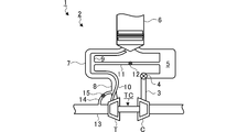
- FIG. 1 is a diagram showing an outline of an engine and an intake / exhaust mechanism of an engine.
- FIG. 2 is a schematic cross-sectional view of the turbocharger.
- FIG. 3 is a sectional view taken along line III-III of FIG.
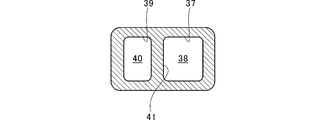
- FIG. 4 is an IV arrow view of FIG.
- FIG. 5 is an extracted view of the broken line portion of FIG.
- FIG. 6 is a diagram for explaining valve opening.
- FIG. 7 is a diagram for explaining a modified example.
- FIG. 8 is a cross-sectional view of a position corresponding to FIG. 5 in the modified example.
- FIG. 1 is a diagram showing an outline of an engine 1 and an intake / exhaust mechanism 2 of the engine 1.
- the intake / exhaust mechanism 2 has a supercharger TC.
- the compressor C of the turbocharger TC is provided in the intake flow path 3.
- a throttle valve 4 and a surge tank 5 are provided on the downstream side of the compressor C in the intake flow path 3.
- the engine 1 has a plurality of cylinders 6. Intake is supplied from the surge tank 5 to each cylinder 6.
- the exhaust gas discharged from some of the cylinders 6 merges at the first collecting portion 7.
- the first upper flow path 8 of the turbine T is connected to the first collecting portion 7. Exhaust gas is supplied to the turbine T of the turbocharger TC through the first collecting portion 7 and the first upper flow path 8.
- the exhaust gas discharged from the remaining cylinders 6 merges at the second collecting portion 9.
- the second upper flow path 10 of the turbine T is connected to the second collecting portion 9. Exhaust gas is supplied to the turbine T of the turbocharger TC through the second collecting portion 9 and the second upper flow path 10.
- the flow path width from the cylinder 6 to the second gathering portion 9 is narrower than the flow path width from the cylinder 6 to the first gathering portion 7.
- the flow path width from the cylinder 6 to the second gathering portion 9 may be the same as the flow path width from the cylinder 6 to the first gathering portion 7.
- the flow path width of the second gathering portion 9 is narrower than the flow path width of the first gathering portion 7.
- the flow path width of the second gathering portion 9 may be the same as the flow path width of the first gathering portion 7.
- the flow path width of the second upper flow path 10 is narrower than the flow path width of the first upper flow path 8.
- the flow path width of the second upper flow path 10 may be the same as the flow path width of the first upper flow path 8.
- the EGR valve 12 is provided in the EGR flow path 11. When the EGR valve 12 is opened, exhaust gas flows from the second collecting portion 9 to the surge tank 5.
- the opening degree of the EGR valve 12 may be arbitrarily controllable between fully open and fully closed.
- the intake / exhaust mechanism 2 is provided with HP-EGR (High Pressure-Exhaust Gas Recirculation).
- the turbine T is provided with an exhaust pipe 13 (downstream side flow path) and a wastegate flow path 14. Exhaust gas is discharged from the turbine T through the exhaust pipe 13.
- the wastegate flow path 14 (second wastegate flow path) is connected to the first upper flow path 8 and the exhaust pipe 13.
- An on-off valve 15 is provided in the wastegate flow path 14.
- the wastegate flow path 14 is opened and closed by the on-off valve 15. The opening degree of the on-off valve 15 may be arbitrarily controllable between fully open and fully closed.
- FIG. 2 is a schematic cross-sectional view of the turbocharger TC.
- the supercharger TC includes a supercharger main body 21.
- the supercharger main body 21 includes a bearing housing 22.
- the turbine housing 24 is connected to the left side of the bearing housing 22 by the fastening mechanism 23.
- the fastening mechanism 23 is composed of, for example, a G coupling.
- the bearing housing 22 and the turbine housing 24 are band-fastened by the fastening mechanism 23.
- the compressor housing 26 is connected to the right side of the bearing housing 22 by a fastening bolt 25.
- the fastening bolt 25 side functions as the turbine T.
- the compressor housing 26 side functions as the compressor C.
- a bearing hole 22a is formed in the bearing housing 22.
- the bearing hole 22a penetrates the supercharger TC in the left-right direction.
- the bearing 27 is provided in the bearing hole 22a.
- a fully floating bearing is shown as an example of the bearing 27.
- the bearing 27 may be another radial bearing such as a semi-floating bearing or a rolling bearing.
- the shaft 28 is rotatably supported by the bearing 27.
- a turbine impeller 29 is provided at the left end of the shaft 28.
- the turbine impeller 29 is rotatably accommodated in the accommodation space S formed in the turbine housing 24.
- a compressor impeller 30 is provided at the right end of the shaft 28.
- the compressor impeller 30 is rotatably housed in the compressor housing 26.
- An intake port 31 is formed in the compressor housing 26.
- the intake port 31 opens on the right side of the turbocharger TC.
- the upstream side of the compressor C in the above intake flow path 3 is connected to the intake port 31.
- the diffuser flow path 32 boosts air.
- the diffuser flow path 32 is formed in an annular shape from the inside to the outside in the radial direction (hereinafter, simply referred to as the radial direction) of the shaft 28.
- the radial inside of the diffuser flow path 32 communicates with the intake port 31 via the compressor impeller 30.
- a compressor scroll flow path 33 is formed inside the compressor housing 26.
- the compressor scroll flow path 33 has an annular shape.
- the compressor scroll flow path 33 is located, for example, outside the diffuser flow path 32 in the radial direction of the shaft 28.
- the downstream side of the compressor C is connected to the compressor scroll flow path 33.
- the compressor scroll flow path 33 communicates with the diffuser flow path 32.
- a discharge flow path 34 (downstream side flow path) is formed in the turbine housing 24.
- the discharge flow path 34 opens on the left side of the turbocharger TC.
- the exhaust pipe 13 is connected to the discharge flow path 34.
- the discharge flow path 34 communicates with the accommodation space S.
- the discharge flow path 34 extends from the turbine impeller 29 in the rotation axis direction (hereinafter, simply referred to as the rotation axis direction) of the turbine impeller 29.
- the turbine housing 24 is provided with a first turbine scroll flow path 35 (the other turbine scroll flow path) and a second turbine scroll flow path 36 (one turbine scroll flow path).
- the first turbine scroll flow path 35 and the second turbine scroll flow path 36 are located outside the accommodation space S in the radial direction and are connected to the accommodation space S.
- the first turbine scroll flow path 35 communicates with the first upper flow path 8.
- the second turbine scroll flow path 36 communicates with the second upper flow path 10. Exhaust gas guided from the first upper flow path 8 and the second upper flow path 10 to the first turbine scroll flow path 35 and the second turbine scroll flow path 36 is guided to the discharge flow path 34 via the blades of the turbine impeller 29. Be taken.
- the turbine impeller 29 rotates in the exhaust gas distribution process.
- the second turbine scroll flow path 36 has a smaller flow path cross-sectional area than the first turbine scroll flow path 35.
- the flow path cross-sectional area is, for example, as shown in FIG. 2, the area in the cross section of the turbine impeller 29 in a plane including the rotation axis.
- the second turbine scroll flow path 36 is located on the left side (the side separated from the bearing housing 22 or the bearing 27) in FIG. 2 with respect to the first turbine scroll flow path 35.
- the first turbine scroll flow path 35 extends to the outside in the radial direction with respect to the second turbine scroll flow path 36.
- the first turbine scroll flow path 35 may extend outward in the radial direction to approximately the same position as the second turbine scroll flow path 36.
- the second turbine scroll flow path 36 may extend to the outside in the radial direction with respect to the first turbine scroll flow path 35. Even in this case, the second turbine scroll is due to a difference in shape such that the length of the first turbine scroll flow path 35 in the rotation axis direction is longer than the length of the second turbine scroll flow path 36 in the rotation axis direction.
- the flow path 36 has a smaller flow path cross-sectional area than the first turbine scroll flow path 35.
- FIG. 3 is a sectional view taken along line III-III of FIG.
- FIG. 3 shows a view in which the turbine housing 24 is cut in a plane perpendicular to the axial direction of the shaft 28 and passing through the first turbine scroll flow path 35.
- the turbine impeller 29 is represented by a circle.
- a first gas inflow port 37 is formed in the turbine housing 24.
- the first gas inflow port 37 opens to the outside of the turbine housing 24.
- the first upper flow path 8 is connected to the first gas inflow port 37.
- a first introduction path 38 is formed between the first gas inflow port 37 and the first turbine scroll flow path 35.
- the first introduction path 38 extends substantially in a straight line.
- the first gas inflow port 37 communicates with the first turbine scroll flow path 35 via the first introduction path 38.
- the second turbine scroll flow path 36 is located on the back side of the paper in FIG. 3 with respect to the first turbine scroll flow path 35.
- FIG. 4 is an IV arrow view of FIG.
- the second gas inflow port 39 is arranged side by side with the first gas inflow port 37.
- the second upper flow path 10 is connected to the second gas inflow port 39.
- the second gas inflow port 39 is smaller than the first gas inflow port 37.
- the second gas inflow port 39 may have approximately the same size as the first gas inflow port 37.
- a second introduction path 40 is formed between the second gas inflow port 39 and the second turbine scroll flow path 36.
- the flow path cross-sectional area of the second introduction path 40 is smaller than the flow path cross-sectional area of the first introduction path 38.
- the flow path cross-sectional area of the second introduction path 40 may be approximately equal to the flow path cross-sectional area of the first introduction path 38.
- the second gas inflow port 39 communicates with the second turbine scroll flow path 36 via the second introduction path 40.
- the partition wall 41 partitions the first turbine scroll flow path 35 and the second turbine scroll flow path 36, the first gas inflow port 37 and the second gas inflow port 39, and the first introduction path 38 and the second introduction path 40, respectively ( See FIGS. 2, 3, and 4).
- the tongue portion 42 is provided in the downstream portion 35a of the first turbine scroll flow path 35.
- the tongue portion 42 partitions the downstream portion 35a and the upstream portion 35b of the first turbine scroll flow path 35.
- the tongue portion 43 is formed on the back side of the paper surface in FIG. 3 with respect to the tongue portion 42.
- the tongue portion 43 is provided in the downstream portion of the second turbine scroll flow path 36, and partitions the downstream portion and the upstream portion.
- the turbine T is a so-called twin scroll turbine.
- FIG. 5 is an extracted view of the broken line portion of FIG.
- the cross section shown in FIG. 5 differs from the cross section shown in FIG. 2 in the position of the turbine impeller 29 in the rotational direction.
- a wastegate flow path 44 (first wastegate flow path) is formed in the turbine housing 24.
- the wastegate flow path 44 opens into the second turbine scroll flow path 36 and the discharge flow path 34.
- the wastegate flow path 44 communicates the second turbine scroll flow path 36 and the discharge flow path 34 without passing through the accommodation space S (turbine impeller 29).
- the wastegate flow path 44 has a valve chamber 44a, a first through hole 44b, and a second through hole 44c.
- the valve chamber 44a is located outside the turbine housing 24 in the radial direction of the discharge flow path 34.
- the first through hole 44b penetrates the turbine housing 24 from the valve chamber 44a to the second turbine scroll flow path 36.
- the first through hole 44b extends in the direction of the rotation axis, for example.
- the second through hole 44c penetrates the turbine housing 24 from the valve chamber 44a to the discharge flow path 34.
- the second through hole 44c extends, for example, in the radial direction.
- a valve 45 is provided in the valve chamber 44a. Of the inner wall surface of the valve chamber 44a, the opening through which the first through hole 44b opens is the seat surface 46. The valve 45 comes into contact with the seat surface 46 when the valve is closed. In this state, the wastegate flow path 44 is closed and the exhaust gas does not flow.
- FIG. 6 is a diagram for explaining the opening of the valve 45.
- the valve 45 is opened and closed by, for example, a drive mechanism (not shown) composed of an actuator.
- a drive mechanism (not shown) composed of an actuator.
- FIG. 6 when the valve 45 is separated from the seat surface 46 and opened, a part of the exhaust gas flows out from the second turbine scroll flow path 36 through the wastegate flow path 44 to the discharge flow path 34. To do. As a result, over-rotation of the turbine T (supercharger TC) is suppressed.
- the wastegate flow path 44 is separated from the first turbine scroll flow path 35 and is not connected to the first turbine scroll flow path 35. That is, the wastegate flow path 44 does not open into the first turbine scroll flow path 35.
- the wastegate flow path 44 opens to both the first turbine scroll flow path 35 and the second turbine scroll flow path 36.
- the first turbine scroll flow path 35 the flow of exhaust gas is disturbed due to the influence of the opening of the wastegate flow path 44. Therefore, a pressure loss of exhaust gas occurs.
- the pressure loss of the exhaust gas is suppressed.
- wastegate flow path 44 When the wastegate flow path 44 opens to both the first turbine scroll flow path 35 and the second turbine scroll flow path 36, exhaust gas leaks from the first turbine scroll flow path 35 to the second turbine scroll flow path 36. There is a possibility. By opening the wastegate flow path 44 only to the second turbine scroll flow path 36, such leakage of exhaust gas is avoided.
- the turbine efficiency of the second turbine scroll flow path 36 is lower than that of the first turbine scroll flow path 35 under predetermined operating conditions.
- the flow rate of the exhaust gas is too large, the exhaust gas flows out into the wastegate flow path 44 only from the second turbine scroll flow path 36 having the lower turbine efficiency.
- the first turbine scroll flow path 35 having the higher turbine efficiency is effectively used.
- the flow path cross-sectional area of the second turbine scroll flow path 36 is smaller than the flow path cross-sectional area of the first turbine scroll flow path 35. Therefore, the first turbine scroll flow path 35 has a wider operating region with high turbine efficiency than the second turbine scroll flow path 36. Since the exhaust gas flows out to the wastegate flow path 44 only from the second turbine scroll flow path 36, the decrease in turbine efficiency is suppressed in a wide operating range.
- the wastegate flow path 44 opens into the second turbine scroll flow path 36 and the discharge flow path 34.
- the second turbine scroll flow path 36 is located on the side separated from the bearing housing 22 or the bearing 27 with respect to the first turbine scroll flow path 35. Therefore, the second turbine scroll flow path 36 is closer to the discharge flow path 34 than the first turbine scroll flow path 35, and the wastegate flow path 44 can be easily installed.
- the second turbine scroll flow path 36 may be located closer to the bearing housing 22 or the bearing 27 than the first turbine scroll flow path 35.
- FIG. 7 is a diagram for explaining a modified example. Similar to the above-described embodiment, the first upper flow path 8 communicates with the first turbine scroll flow path 135 (the other turbine scroll flow path) of the modified example.
- the second upper flow path 10 communicates with the second turbine scroll flow path 136 (one turbine scroll flow path).
- the second turbine scroll flow path 136 is located inside the shaft 28 in the radial direction with respect to the first turbine scroll flow path 135.
- the second turbine scroll flow path 136 extends radially outside the turbine impeller 29 over approximately half a circumference.
- the second turbine scroll flow path 136 faces the turbine impeller 29 in the radial direction over approximately half a circumference.
- the first turbine scroll flow path 135 extends to the outside of the turbine impeller 29 in the radial direction over approximately the entire circumference. Of the first turbine scroll flow path 135, approximately half of the circumference of the turbine impeller 29 is interposed between the turbine impeller 29 and the second turbine scroll flow path 136. The first turbine scroll flow path 135 faces the turbine impeller 29 in the radial direction over approximately half a circumference, which is the remaining portion where the second turbine scroll flow path 136 does not intervene.
- the tongue portion 142 is provided in the downstream portion 135a of the first turbine scroll flow path 135.
- the tongue portion 142 partitions the downstream portion 135a of the first turbine scroll flow path 135 and the upstream portion 136b of the second turbine scroll flow path 136.
- the tongue portion 143 is provided in the downstream portion of the second turbine scroll flow path 136.
- the tongue portion 143 partitions the downstream portion 136a of the second turbine scroll flow path 136 and the upstream portion 135b of the first turbine scroll flow path 135.
- the tongue portions 142 and 143 are arranged at positions shifted by 180 degrees in the rotational direction of the turbine impeller 29. However, the position of the tongue portion 143 in the rotation direction of the turbine impeller 29 may be different from that of the tongue portion 142. As described above, the turbine T is a so-called double scroll turbine.
- the second turbine scroll flow path 136 is located inside the shaft 28 in the radial direction with respect to the first turbine scroll flow path 135 .
- the second turbine scroll flow path 136 may be located outside the shaft 28 in the radial direction with respect to the first turbine scroll flow path 135.
- FIG. 8 is a cross-sectional view of a position corresponding to FIG. 5 in the modified example.
- the second turbine scroll flow path 136 has a smaller flow path cross-sectional area than the first turbine scroll flow path 135.
- a wastegate flow path 44 is formed in the turbine housing 24. The wastegate flow path 44 opens into the second turbine scroll flow path 136 and the discharge flow path 34.
- the wastegate flow path 44 has a valve chamber 44a, a first through hole 44b, and a second through hole 44c.
- the wastegate flow path 44 has substantially the same configuration as the wastegate flow path 44 described above.
- the valve 45 provided in the valve chamber 44a is opened and closed by, for example, a drive mechanism (not shown) composed of an actuator. When the valve 45 is opened, a part of the exhaust gas flows out from the second turbine scroll flow path 136 through the wastegate flow path 44 to the discharge flow path 34. As a result, over-rotation of the turbine T is suppressed.
- the pressure loss of the exhaust gas is suppressed by opening the wastegate flow path 44 only in the second turbine scroll flow path 136, as in the above-described embodiment.
- the second turbine scroll flow path 136 has lower turbine efficiency under predetermined operating conditions than the first turbine scroll flow path 135. Similar to the above-described embodiment, the first turbine scroll flow path 135 having higher turbine efficiency is effectively used.
- the flow path cross-sectional area of the second turbine scroll flow path 136 is smaller than the flow path cross-sectional area of the first turbine scroll flow path 135. Therefore, the first turbine scroll flow path 135 has a wider operating region with high turbine efficiency than the second turbine scroll flow path 136. Since the exhaust gas flows out to the wastegate flow path 44 only from the second turbine scroll flow path 136, the decrease in turbine efficiency is suppressed in a wide operating range.
- the turbine T of the turbocharger TC has been described as an example.
- a turbine T incorporated in a device other than the turbocharger TC or a single turbine T may be used.
- the turbine T includes the first upper flow path 8, the second upper flow path 10, the exhaust pipe 13, and the wastegate flow path 14 has been described.
- the first upper flow path 8, the second upper flow path 10, the exhaust pipe 13, and the wastegate flow path 14 may be provided separately from the turbine T.
- wastegate flow path 14 is connected to the exhaust pipe 13
- the wastegate flow path 14 may be connected to the discharge flow path 34.
- wastegate flow path 44 opens to the second turbine scroll flow path 36, 136
- the wastegate flow path 44 may communicate with the second turbine scroll flow path 36, 136, and may be opened to, for example, the second introduction path 40.
- the wastegate flow path 14 since the exhaust gas of the first upper flow path 8 flows out from the wastegate flow path 14 to the exhaust pipe 13, the over-rotation of the turbine T is further suppressed. Further, the first upper flow path 8 has a larger flow path cross-sectional area than the first turbine scroll flow paths 35 and 135. Since the wastegate flow path 14 opens in the first upper flow path 8, the turbulence of the exhaust gas flow due to the opening is larger than that in the case where the wastegate flow path 14 opens in the first turbine scroll flow paths 35 and 135. The impact is small.
- the flow path cross-sectional area of the second turbine scroll flow paths 36 and 136 is smaller than the flow path cross-sectional areas of the first turbine scroll flow paths 35 and 135 has been described.
- the flow path cross-sectional area of the second turbine scroll flow paths 36 and 136 may be larger than the flow path cross-sectional areas of the first turbine scroll flow paths 35 and 135.
- the flow path cross-sectional area of the second turbine scroll flow paths 36 and 136 may be approximately equal to the flow path cross-sectional areas of the first turbine scroll flow paths 35 and 135.
- the exhaust pressure of the second upper flow path 10 located upstream of the second turbine scroll flow path 36, 136, which has a small flow path cross-sectional area, is higher than that of the first upper flow path 8.
- the EGR valve 12 opens, and the exhaust gas efficiently flows out from the second upper flow path 10 having a high exhaust pressure to the EGR flow path 11.
- the valve 45 is opened, and the exhaust gas efficiently flows out from the second turbine scroll flow path 36, 136, which has a high exhaust pressure, to the wastegate flow path 44.
- the EGR flow path 11 does not have to be open in the second upper flow path 10.
- This disclosure can be used for turbines and turbochargers.
Landscapes
- Engineering & Computer Science (AREA)
- Mechanical Engineering (AREA)
- General Engineering & Computer Science (AREA)
- Chemical & Material Sciences (AREA)
- Combustion & Propulsion (AREA)
- Chemical Kinetics & Catalysis (AREA)
- General Chemical & Material Sciences (AREA)
- Supercharger (AREA)
Abstract
タービンTは、収容空間に収容されたタービンインペラと、収容空間に接続される2つのタービンスクロール流路と、一方のタービンスクロール流路(第2タービンスクロール流路36)に開口し、他方のタービンスクロール流路(第1タービンスクロール流路35)に対して離隔する第1ウェイストゲート流路(ウェイストゲート流路44)と、第1ウェイストゲート流路を開閉するバルブ45と、を備える。
Description
本開示は、タービンおよび過給機に関する。本出願は2019年4月10日に提出された日本特許出願第2019-075015号に基づく優先権の利益を主張するものであり、その内容は本出願に援用される。
過給機などに設けられるタービンにおいて、2つのタービンスクロール流路が設けられるものがある。例えば、特許文献1に記載の過給機では、2つのタービンスクロール流路の内壁面に開口するウェイストゲート流路が形成されている。排気ガスの流量が多すぎる場合、排気ガスは、ウェイストゲート流路を通ってタービンインペラを迂回して流れる。その結果、過給機の過回転が抑制される。
上記の特許文献1に記載のように、タービンスクロール流路の内壁面には、ウェイストゲート流路が開口している。ウェイストゲート流路が閉じられていたとしても、ウェイストゲート流路の開口部の影響により、排気ガスの流れが乱れる。そのため、排気ガスの圧力損失が生じてしまう。
本開示の目的は、排気ガスの圧力損失を抑制することが可能なタービンおよび過給機を提供することである。
上記課題を解決するために、本開示の一態様に係るタービンは、収容空間に収容されたタービンインペラと、収容空間に接続される2つのタービンスクロール流路と、一方のタービンスクロール流路に連通し、他方のタービンスクロール流路に対して離隔する第1ウェイストゲート流路と、第1ウェイストゲート流路を開閉するバルブと、を備える。
他方のタービンスクロール流路の上流側に接続される第1上流路と、タービンインペラより下流に位置し、収容空間に連通する下流側流路と、第1上流路および下流側流路に接続される第2ウェイストゲート流路と、を備えてもよい。
2つのタービンスクロール流路それぞれの下流部に設けられた舌部は、タービンインペラの回転方向の位置が、互いに異なってもよい。
2つのタービンスクロール流路それぞれの下流部に設けられた舌部は、タービンインペラの回転方向の位置が、互いに同じであってもよい。
一方のタービンスクロール流路は、他方のタービンスクロール流路よりも、流路断面積が小さくてもよい。
タービンより上流に位置し、一方のタービンスクロール流路に連通し、EGR流路が開口する第2上流路を備えてもよい。
上記課題を解決するために、本開示の一態様に係る過給機は、上記タービンを備える。
本開示によれば、排気ガスの圧力損失を抑制することが可能となる。
以下に添付図面を参照しながら、本開示の一実施形態について詳細に説明する。実施形態に示す寸法、材料、その他具体的な数値等は、理解を容易とするための例示にすぎず、特に断る場合を除き、本開示を限定するものではない。なお、本明細書および図面において、実質的に同一の機能、構成を有する要素については、同一の符号を付することにより重複説明を省略する。また本開示に直接関係のない要素は図示を省略する。
図1は、エンジン1およびエンジン1の吸排気機構2の概略を示す図である。図1に示すように、吸排気機構2は、過給機TCを有する。過給機TCのコンプレッサCは、吸気流路3に設けられる。吸気流路3のうち、コンプレッサCの下流側には、スロットルバルブ4およびサージタンク5が設けられる。図1では、1つの気筒6のみが示されるが、エンジン1は、複数の気筒6を有している。サージタンク5からそれぞれの気筒6に吸気が供給される。
複数の気筒6のうち、一部の気筒6から排出された排気ガスは、第1集合部7で合流する。第1集合部7には、タービンTの第1上流路8が接続されている。第1集合部7および第1上流路8を通って、過給機TCのタービンTに排気ガスが供給される。
複数の気筒6のうち、残りの気筒6から排出された排気ガスは、第2集合部9で合流する。第2集合部9には、タービンTの第2上流路10が接続されている。第2集合部9および第2上流路10を通って、過給機TCのタービンTに排気ガスが供給される。
図1では、気筒6から第2集合部9までの流路幅は、気筒6から第1集合部7までの流路幅よりも狭い。ただし、気筒6から第2集合部9までの流路幅は、気筒6から第1集合部7までの流路幅と同等であってもよい。第2集合部9の流路幅は、第1集合部7の流路幅よりも狭い。ただし、第2集合部9の流路幅は、第1集合部7の流路幅と同等であってもよい。第2上流路10の流路幅は、第1上流路8の流路幅よりも狭い。ただし、第2上流路10の流路幅は、第1上流路8の流路幅と同等であってもよい。
第2集合部9には、EGR流路11の一端が接続される。EGR流路11の他端は、サージタンク5に接続される。EGR流路11には、EGRバルブ12が設けられる。EGRバルブ12が開弁すると、第2集合部9からサージタンク5に排気ガスが流れる。EGRバルブ12の開度は、全開と全閉の間で、任意に制御可能であってもよい。このように、吸排気機構2には、HP-EGR(High Pressure - Exhaust Gas Recirculation)が設けられる。
タービンTには、排気管13(下流側流路)およびウェイストゲート流路14が設けられる。排気ガスは、排気管13を通ってタービンTから排出される。ウェイストゲート流路14(第2ウェイストゲート流路)は、第1上流路8および排気管13に接続される。ウェイストゲート流路14には、開閉バルブ15が設けられる。開閉バルブ15によって、ウェイストゲート流路14が開閉される。開閉バルブ15の開度は、全開と全閉の間で、任意に制御可能であってもよい。
図2は、過給機TCの概略断面図である。図2では、タービンTのうち、上記の第1上流路8、第2上流路10、排気管13、ウェイストゲート流路14の図示が省略される。図2に示す矢印L方向を過給機TCの左側として説明する。図2に示す矢印R方向を過給機TCの右側として説明する。図2に示すように、過給機TCは、過給機本体21を備える。過給機本体21は、ベアリングハウジング22を備える。
ベアリングハウジング22の左側には、締結機構23によってタービンハウジング24が連結される。締結機構23は、例えば、Gカップリングで構成される。ベアリングハウジング22とタービンハウジング24は、締結機構23によってバンド締結される。ベアリングハウジング22の右側には、締結ボルト25によってコンプレッサハウジング26が連結される。過給機TCのうち、締結ボルト25側は、タービンTとして機能する。過給機TCのうち、コンプレッサハウジング26側は、コンプレッサCとして機能する。
ベアリングハウジング22には、軸受孔22aが形成されている。軸受孔22aは、過給機TCの左右方向に貫通する。軸受孔22aに軸受27が設けられる。図2では、軸受27の一例としてフルフローティング軸受が示される。ただし、軸受27は、セミフローティング軸受または転がり軸受など、他のラジアル軸受であってもよい。軸受27によって、シャフト28が回転自在に軸支されている。シャフト28の左端部にはタービンインペラ29が設けられる。タービンハウジング24内に形成された収容空間Sに、タービンインペラ29が回転自在に収容されている。また、シャフト28の右端部にはコンプレッサインペラ30が設けられる。コンプレッサインペラ30がコンプレッサハウジング26内に回転自在に収容されている。
コンプレッサハウジング26には、吸気口31が形成される。吸気口31は、過給機TCの右側に開口する。吸気口31には、上記の吸気流路3のうち、コンプレッサCの上流側が接続される。また、締結ボルト25によってベアリングハウジング22とコンプレッサハウジング26が連結された状態では、ディフューザ流路32が形成される。ディフューザ流路32は、空気を昇圧する。ディフューザ流路32は、シャフト28の径方向(以下、単に径方向という)の内側から外側に向けて環状に形成されている。ディフューザ流路32の径方向の内側は、コンプレッサインペラ30を介して吸気口31に連通している。
また、コンプレッサハウジング26の内部には、コンプレッサスクロール流路33が形成される。コンプレッサスクロール流路33は環状形状である。コンプレッサスクロール流路33は、例えばディフューザ流路32よりもシャフト28の径方向の外側に位置する。コンプレッサスクロール流路33には、上記の吸気流路3のうち、コンプレッサCの下流側が接続される。コンプレッサスクロール流路33は、ディフューザ流路32に連通している。
コンプレッサインペラ30が回転すると、吸気口31からコンプレッサハウジング26内に空気が吸気される。吸気された空気は、コンプレッサインペラ30の翼間を流通する過程において、遠心力の作用により増速される。増速された空気は、ディフューザ流路32およびコンプレッサスクロール流路33で昇圧される。昇圧された空気は、サージタンク5を通ってそれぞれの気筒6に導かれる。
タービンハウジング24には、吐出流路34(下流側流路)が形成されている。吐出流路34は、過給機TCの左側に開口する。吐出流路34には、上記の排気管13が接続される。吐出流路34は、収容空間Sに連通する。吐出流路34は、タービンインペラ29から、タービンインペラ29の回転軸方向(以下、単に回転軸方向という)に延在する。
タービンハウジング24には、第1タービンスクロール流路35(他方のタービンスクロール流路)、第2タービンスクロール流路36(一方のタービンスクロール流路)が設けられている。第1タービンスクロール流路35および第2タービンスクロール流路36は、収容空間Sよりも径方向の外側に位置し、収容空間Sに接続される。第1タービンスクロール流路35は、第1上流路8と連通する。第2タービンスクロール流路36は、第2上流路10と連通する。第1上流路8、第2上流路10から第1タービンスクロール流路35、第2タービンスクロール流路36に導かれた排気ガスは、タービンインペラ29の翼間を介して吐出流路34に導かれる。排気ガスの流通過程において、タービンインペラ29が回転する。
第2タービンスクロール流路36は、第1タービンスクロール流路35よりも流路断面積が小さい。ここで、流路断面積は、例えば、図2に示すように、タービンインペラ29の回転軸を含む平面による断面における面積である。また、第2タービンスクロール流路36は、第1タービンスクロール流路35よりも、図2中、左側(ベアリングハウジング22または軸受27から離隔する側)に位置する。第1タービンスクロール流路35は、第2タービンスクロール流路36よりも、径方向の外側まで延在する。ただし、第1タービンスクロール流路35は、径方向の外側に、第2タービンスクロール流路36と大凡同じ位置まで延在してもよい。第2タービンスクロール流路36が、第1タービンスクロール流路35よりも、径方向の外側まで延在してもよい。この場合であっても、第1タービンスクロール流路35の回転軸方向の長さが、第2タービンスクロール流路36の回転軸方向の長さよりも長いなどの形状の差により、第2タービンスクロール流路36は、第1タービンスクロール流路35よりも流路断面積が小さい。
図3は、図2のIII-III線断面図である。図3では、シャフト28の軸方向に垂直かつ第1タービンスクロール流路35を通る平面で、タービンハウジング24を切断した図を示す。図3では、タービンインペラ29が円で示される。図3に示すように、タービンハウジング24には、第1ガス流入口37が形成される。第1ガス流入口37は、タービンハウジング24の外部に開口する。第1ガス流入口37に上記の第1上流路8が接続される。
第1ガス流入口37と第1タービンスクロール流路35との間には、第1導入路38が形成される。第1導入路38は、大凡直線状に延在する。第1ガス流入口37は、第1導入路38を介して第1タービンスクロール流路35に連通する。第2タービンスクロール流路36は、第1タービンスクロール流路35に対し、図3における紙面奥側に位置する。
図4は、図3のIV矢視図である。図4に示すように、第2ガス流入口39は、第1ガス流入口37に並設される。第2ガス流入口39に上記の第2上流路10が接続される。第2ガス流入口39は、第1ガス流入口37よりも小さい。ただし、第2ガス流入口39は、第1ガス流入口37と大凡同じ大きさであってもよい。
第2ガス流入口39と第2タービンスクロール流路36との間には、第2導入路40が形成される。第2導入路40の流路断面積は、第1導入路38の流路断面積よりも小さい。ただし、第2導入路40の流路断面積は、第1導入路38の流路断面積と大凡等しくてもよい。第2ガス流入口39は、第2導入路40を介して第2タービンスクロール流路36に連通する。
隔壁41は、第1タービンスクロール流路35と第2タービンスクロール流路36、第1ガス流入口37と第2ガス流入口39、第1導入路38と第2導入路40を、それぞれ仕切る(図2、図3、図4参照)。
タービンハウジング24には、2つの舌部42、43が形成される。舌部42は、第1タービンスクロール流路35の下流部35aに設けられる。舌部42は、第1タービンスクロール流路35の下流部35aと上流部35bを仕切る。舌部43は、舌部42に対して、図3中、紙面奥側に形成される。舌部43は、舌部42と同様、第2タービンスクロール流路36の下流部に設けられ、下流部と上流部を仕切る。
2つの舌部42、43は、タービンインペラ29の回転方向の位置が互いに同じである。このように、タービンTは、いわゆるツインスクロールタービンである。
図5は、図2の破線部分の抽出図である。図5に示す断面は、図2に示す断面に対してタービンインペラ29の回転方向の位置が異なる。図5に示すように、タービンハウジング24には、ウェイストゲート流路44(第1ウェイストゲート流路)が形成される。ウェイストゲート流路44は、第2タービンスクロール流路36および吐出流路34に開口する。ウェイストゲート流路44は、収容空間S(タービンインペラ29)を介さずに、第2タービンスクロール流路36と吐出流路34を連通させる。
ウェイストゲート流路44は、バルブ室44a、第1貫通孔44b、第2貫通孔44cを有する。バルブ室44aは、タービンハウジング24のうち、吐出流路34の径方向の外側に位置する。第1貫通孔44bは、タービンハウジング24を、バルブ室44aから第2タービンスクロール流路36まで貫通する。第1貫通孔44bは、例えば、回転軸方向に延在する。第2貫通孔44cは、タービンハウジング24を、バルブ室44aから吐出流路34まで貫通する。第2貫通孔44cは、例えば、径方向に延在する。
バルブ室44aには、バルブ45が設けられる。バルブ室44aの内壁面のうち、第1貫通孔44bが開口する開口部は、シート面46となっている。バルブ45は、閉弁時、シート面46に当接する。この状態では、ウェイストゲート流路44は閉じられ、排気ガスが流通しない。
図6は、バルブ45の開弁を説明するための図である。バルブ45は、例えば、アクチュエータで構成される不図示の駆動機構により、開閉される。図6に示すように、バルブ45がシート面46から離隔して開弁すると、排気ガスの一部は、第2タービンスクロール流路36からウェイストゲート流路44を通って吐出流路34に流出する。これにより、タービンT(過給機TC)の過回転が抑制される。
ウェイストゲート流路44は、第1タービンスクロール流路35に対して離隔しており、第1タービンスクロール流路35に接続されない。つまり、ウェイストゲート流路44は、第1タービンスクロール流路35に開口しない。例えば、ウェイストゲート流路44が、第1タービンスクロール流路35および第2タービンスクロール流路36の双方に開口する場合も考えられる。この場合、第1タービンスクロール流路35において、ウェイストゲート流路44の開口部の影響により、排気ガスの流れが乱れる。そのため、排気ガスの圧力損失が生じてしまう。ウェイストゲート流路44が、第2タービンスクロール流路36のみに開口することにより、排気ガスの圧力損失が抑制される。ウェイストゲート流路44が、第1タービンスクロール流路35および第2タービンスクロール流路36の双方に開口する場合、第1タービンスクロール流路35から第2タービンスクロール流路36に排気ガスが漏出する可能性がある。ウェイストゲート流路44が、第2タービンスクロール流路36のみに開口することにより、このような排気ガスの漏出が回避される。
第2タービンスクロール流路36の方が、第1タービンスクロール流路35よりも、所定の運転条件においてタービン効率が低い。排気ガスの流量が多すぎるときには、ウェイストゲート流路44には、タービン効率が低い方の第2タービンスクロール流路36からのみ、排気ガスが流出する。これにより、タービン効率が高い方の第1タービンスクロール流路35が有効に用いられる。
上記のように、第2タービンスクロール流路36の流路断面積の方が、第1タービンスクロール流路35の流路断面積よりも小さい。そのため、第1タービンスクロール流路35は、第2タービンスクロール流路36に対して、タービン効率の高い運転領域が広い。第2タービンスクロール流路36からのみ、ウェイストゲート流路44に排気ガスが流出することから、幅広い運転領域で、タービン効率の低下が抑制される。
上記のように、ウェイストゲート流路44は、第2タービンスクロール流路36および吐出流路34に開口する。第2タービンスクロール流路36は、第1タービンスクロール流路35よりも、ベアリングハウジング22または軸受27から離隔する側に位置する。そのため、第2タービンスクロール流路36は、第1タービンスクロール流路35よりも吐出流路34に近く、ウェイストゲート流路44の設置が容易となる。ただし、第2タービンスクロール流路36は、第1タービンスクロール流路35よりも、ベアリングハウジング22または軸受27に近い側に位置してもよい。
図7は、変形例を説明するための図である。上述した実施形態と同様、変形例の第1タービンスクロール流路135(他方のタービンスクロール流路)には、第1上流路8が連通する。第2タービンスクロール流路136(一方のタービンスクロール流路)には、第2上流路10が連通する。図7に示すように、変形例では、第2タービンスクロール流路136は、第1タービンスクロール流路135よりもシャフト28の径方向の内側に位置する。第2タービンスクロール流路136は、タービンインペラ29の径方向の外側に、大凡半周に亘って延在する。第2タービンスクロール流路136は、大凡半周に亘って、タービンインペラ29に対して径方向に対向する。
第1タービンスクロール流路135は、タービンインペラ29の径方向の外側に、大凡全周に亘って延在する。第1タービンスクロール流路135のうち、タービンインペラ29の大凡半周分は、タービンインペラ29との間に第2タービンスクロール流路136が介在する。第1タービンスクロール流路135は、第2タービンスクロール流路136が介在しない残りの部分である大凡半周に亘って、タービンインペラ29に対して径方向に対向する。
タービンハウジング24には、2つの舌部142、143が形成される。舌部142は、第1タービンスクロール流路135の下流部135aに設けられる。舌部142は、第1タービンスクロール流路135の下流部135aと、第2タービンスクロール流路136の上流部136bを仕切る。舌部143は、第2タービンスクロール流路136の下流部に設けられる。舌部143は、第2タービンスクロール流路136の下流部136aと、第1タービンスクロール流路135の上流部135bを仕切る。
舌部142、143は、互いにタービンインペラ29の回転方向に180度ずれた位置に配される。ただし、舌部143は、舌部142に対して、タービンインペラ29の回転方向の位置が異なっていればよい。このように、タービンTは、いわゆるダブルスクロールタービンである。
ここでは、第2タービンスクロール流路136は、第1タービンスクロール流路135よりもシャフト28の径方向の内側に位置する場合について説明した。ただし、第2タービンスクロール流路136は、第1タービンスクロール流路135よりもシャフト28の径方向の外側に位置してもよい。
図8は、変形例における図5に対応する位置の断面図である。図8に示すように、第2タービンスクロール流路136は、第1タービンスクロール流路135よりも流路断面積が小さい。タービンハウジング24には、ウェイストゲート流路44が形成される。ウェイストゲート流路44は、第2タービンスクロール流路136および吐出流路34に開口する。
ウェイストゲート流路44は、バルブ室44a、第1貫通孔44b、第2貫通孔44cを有する。ウェイストゲート流路44は、上述したウェイストゲート流路44と実質的に同様の構成である。バルブ室44aに設けられたバルブ45は、例えば、アクチュエータで構成される不図示の駆動機構により、開閉される。バルブ45が開弁すると、排気ガスの一部は、第2タービンスクロール流路136からウェイストゲート流路44を通って吐出流路34に流出する。これにより、タービンTの過回転が抑制される。
変形例においても、上述した実施形態と同様、ウェイストゲート流路44が、第2タービンスクロール流路136のみに開口することにより、排気ガスの圧力損失が抑制される。第2タービンスクロール流路136の方が、第1タービンスクロール流路135よりも、所定の運転条件においてタービン効率が低い。上述した実施形態と同様、タービン効率が高い方の第1タービンスクロール流路135が有効に用いられる。
上記のように、第2タービンスクロール流路136の流路断面積の方が、第1タービンスクロール流路135の流路断面積よりも小さい。そのため、第1タービンスクロール流路135は、第2タービンスクロール流路136に対して、タービン効率の高い運転領域が広い。第2タービンスクロール流路136からのみ、ウェイストゲート流路44に排気ガスが流出することから、幅広い運転領域で、タービン効率の低下が抑制される。
以上、添付図面を参照しながら本開示の一実施形態について説明したが、本開示はかかる実施形態に限定されないことは言うまでもない。当業者であれば、特許請求の範囲に記載された範疇において、各種の変更例または修正例に想到し得ることは明らかであり、それらについても当然に本開示の技術的範囲に属するものと了解される。
例えば、上述した実施形態および変形例では、過給機TCのタービンTを例に挙げて説明した。しかし、過給機TC以外の装置に組み込まれたタービンTや、単体のタービンTが用いられてもよい。
上述した実施形態および変形例では、タービンTに、第1上流路8、第2上流路10、排気管13、ウェイストゲート流路14が含まれる場合について説明した。しかし、第1上流路8、第2上流路10、排気管13、ウェイストゲート流路14は、タービンTと別に設けられてもよい。
上述した実施形態および変形例では、ウェイストゲート流路14が、排気管13に接続される場合について説明した。しかし、ウェイストゲート流路14は、吐出流路34に接続されてもよい。
上述した実施形態および変形例では、ウェイストゲート流路44は、第2タービンスクロール流路36、136に開口する場合について説明した。しかし、ウェイストゲート流路44は、第2タービンスクロール流路36、136に連通すればよく、例えば、第2導入路40に開口してもよい。
上述した実施形態および変形例では、ウェイストゲート流路14が設けられる場合について説明した。この場合、第1上流路8の排気ガスがウェイストゲート流路14から排気管13に流出することから、一層、タービンTの過回転が抑制される。また、第1上流路8は、第1タービンスクロール流路35、135よりも流路断面積が大きい。第1上流路8にウェイストゲート流路14が開口することから、第1タービンスクロール流路35、135にウェイストゲート流路14が開口する場合に比べて、開口部による排気ガスの流れの乱れの影響が小さい。
上述した実施形態では、タービンTがツインスクロールタービンである場合について説明した。この場合、第1タービンスクロール流路35と第2タービンスクロール流路36とでは、タービンインペラ29の回転方向の位置に差がない。そのため、ウェイストゲート流路44に排気ガスが流出して、第2タービンスクロール流路36の流量が第1タービンスクロール流路35の流量に対して変化しても、タービンインペラ29の回転軸がぶれ難い。
上述した実施形態および変形例では、第2タービンスクロール流路36、136の流路断面積の方が、第1タービンスクロール流路35、135の流路断面積よりも小さい場合について説明した。ただし、第2タービンスクロール流路36、136の流路断面積の方が、第1タービンスクロール流路35、135の流路断面積よりも大きくてもよい。第2タービンスクロール流路36、136の流路断面積は、第1タービンスクロール流路35、135の流路断面積と大凡等しくてもよい。
上述した実施形態および変形例では、第2上流路10には、EGR流路11が開口する場合について説明した。この場合、流路断面積が小さい第2タービンスクロール流路36、136の上流に位置する第2上流路10では、第1上流路8よりも排気圧が高い。例えば、低負荷領域では、EGRバルブ12が開弁し、排気圧が高い第2上流路10からEGR流路11に排気ガスが効率的に流出する。高負荷領域では、バルブ45が開弁し、排気圧が高い第2タービンスクロール流路36、136からウェイストゲート流路44に排気ガスが効率的に流出する。ただし、第2上流路10には、EGR流路11が開口していなくてもよい。
本開示は、タービンおよび過給機に利用することができる。
8:第1上流路 10:第2上流路 11:EGR流路 13:排気管(下流側流路) 14:ウェイストゲート流路(第2ウェイストゲート流路) 29:タービンインペラ 34:吐出流路(下流側流路) 35:第1タービンスクロール流路(他方のタービンスクロール流路) 35a:下流部 36:第2タービンスクロール流路(一方のタービンスクロール流路) 42:舌部 43:舌部 44:ウェイストゲート流路(第1ウェイストゲート流路) 45:バルブ 135:第1タービンスクロール流路(他方のタービンスクロール流路) 135a:下流部 136:第2タービンスクロール流路(一方のタービンスクロール流路) 136a:下流部 142:舌部 143:舌部 S:収容空間 T:タービン TC:過給機
Claims (7)
- 収容空間に収容されたタービンインペラと、
前記収容空間に接続される2つのタービンスクロール流路と、
一方の前記タービンスクロール流路に連通し、他方の前記タービンスクロール流路に対して離隔する第1ウェイストゲート流路と、
前記第1ウェイストゲート流路を開閉するバルブと、
を備えるタービン。 - 前記他方のタービンスクロール流路の上流側に接続される第1上流路と、
前記タービンインペラより下流に位置し、前記収容空間に連通する下流側流路と、
前記第1上流路および前記下流側流路に接続される第2ウェイストゲート流路と、
を備える請求項1に記載のタービン。 - 前記2つのタービンスクロール流路それぞれの下流部に設けられた舌部は、前記タービンインペラの回転方向の位置が、互いに異なる請求項1または2に記載のタービン。
- 前記2つのタービンスクロール流路それぞれの下流部に設けられた舌部は、前記タービンインペラの回転方向の位置が、互いに同じである請求項1または2に記載のタービン。
- 前記一方のタービンスクロール流路は、前記他方のタービンスクロール流路よりも、流路断面積が小さい請求項1から4のいずれか1項に記載のタービン。
- 前記タービンより上流に位置し、前記一方のタービンスクロール流路に連通し、EGR流路が開口する第2上流路
を備える請求項5に記載のタービン。 - 請求項1から6のいずれか1項に記載の前記タービンを備える過給機。
Priority Applications (4)
| Application Number | Priority Date | Filing Date | Title |
|---|---|---|---|
| DE112020001851.2T DE112020001851T5 (de) | 2019-04-10 | 2020-03-31 | Turbine und Turbolader |
| JP2021513589A JPWO2020209146A1 (ja) | 2019-04-10 | 2020-03-31 | |
| CN202080027244.2A CN113661314A (zh) | 2019-04-10 | 2020-03-31 | 涡轮以及增压器 |
| US17/479,298 US12078097B2 (en) | 2019-04-10 | 2021-09-20 | Turbine and turbocharger |
Applications Claiming Priority (2)
| Application Number | Priority Date | Filing Date | Title |
|---|---|---|---|
| JP2019-075015 | 2019-04-10 | ||
| JP2019075015 | 2019-04-10 |
Related Child Applications (1)
| Application Number | Title | Priority Date | Filing Date |
|---|---|---|---|
| US17/479,298 Continuation US12078097B2 (en) | 2019-04-10 | 2021-09-20 | Turbine and turbocharger |
Publications (1)
| Publication Number | Publication Date |
|---|---|
| WO2020209146A1 true WO2020209146A1 (ja) | 2020-10-15 |
Family
ID=72751101
Family Applications (1)
| Application Number | Title | Priority Date | Filing Date |
|---|---|---|---|
| PCT/JP2020/014893 Ceased WO2020209146A1 (ja) | 2019-04-10 | 2020-03-31 | タービンおよび過給機 |
Country Status (5)
| Country | Link |
|---|---|
| US (1) | US12078097B2 (ja) |
| JP (1) | JPWO2020209146A1 (ja) |
| CN (1) | CN113661314A (ja) |
| DE (1) | DE112020001851T5 (ja) |
| WO (1) | WO2020209146A1 (ja) |
Families Citing this family (1)
| Publication number | Priority date | Publication date | Assignee | Title |
|---|---|---|---|---|
| JP7151866B2 (ja) * | 2019-03-06 | 2022-10-12 | 株式会社Ihi | タービン |
Citations (4)
| Publication number | Priority date | Publication date | Assignee | Title |
|---|---|---|---|---|
| JPS63117124A (ja) * | 1986-11-05 | 1988-05-21 | Ishikawajima Harima Heavy Ind Co Ltd | ツインスクロ−ルタ−ボチヤ−ジヤ付エンジン |
| JP2007154703A (ja) * | 2005-12-02 | 2007-06-21 | Mazda Motor Corp | 過給機付きエンジンの排気ガス温度制御装置 |
| JP2017516016A (ja) * | 2014-05-19 | 2017-06-15 | ボーグワーナー インコーポレーテッド | 非対称デュアル渦巻きを通じる燃料節約及びegr活用のためにパルスエネルギー分離を最適化するデュアル渦巻きターボチャージャ |
| WO2018151267A1 (ja) * | 2017-02-16 | 2018-08-23 | 株式会社Ihi | 過給機 |
Family Cites Families (13)
| Publication number | Priority date | Publication date | Assignee | Title |
|---|---|---|---|---|
| US4245953A (en) * | 1979-01-18 | 1981-01-20 | General Motors Corporation | Engine turbocharger with cartridge wastegate valve |
| JPS6139438U (ja) | 1984-08-14 | 1986-03-12 | トヨタ自動車株式会社 | ツインエントリ−タ−ボチヤ−ジヤ |
| US4813232A (en) | 1986-05-30 | 1989-03-21 | Mazda Motor Corporation | Exhaust device for internal combustion engine |
| JPS6321329A (ja) * | 1986-07-14 | 1988-01-28 | Mazda Motor Corp | エンジンの排気装置 |
| EP1650415A4 (en) * | 2003-07-29 | 2009-06-24 | Hino Motors Ltd | TURBOCHARGER |
| JP4548237B2 (ja) | 2005-06-17 | 2010-09-22 | トヨタ自動車株式会社 | ターボチャージャのツインスクロールタービンハウジング |
| JP5106818B2 (ja) | 2006-10-20 | 2012-12-26 | 三菱重工業株式会社 | ウエストゲートバルブをそなえた排気ターボチャージャの構造 |
| US7363761B1 (en) * | 2006-10-31 | 2008-04-29 | International Engine Intellectual Property Company, Llc | Exhaust gas throttle for divided turbine housing turbocharger |
| JP2008196332A (ja) | 2007-02-09 | 2008-08-28 | Toyota Motor Corp | ターボチャージャ付内燃機関の制御装置 |
| DE102008039086A1 (de) * | 2008-08-21 | 2010-02-25 | Daimler Ag | Abgasturbolader für eine Brennkraftmaschine eines Kraftfahrzeugs |
| JP5589934B2 (ja) | 2011-04-05 | 2014-09-17 | 株式会社デンソー | タービン及びターボチャージャ |
| JP5964056B2 (ja) | 2012-01-11 | 2016-08-03 | 三菱重工業株式会社 | タービンハウジングのスクロール構造 |
| JP6881219B2 (ja) | 2017-10-18 | 2021-06-02 | トヨタ自動車株式会社 | 衝突前制御装置及び衝突前制御方法 |
-
2020
- 2020-03-31 DE DE112020001851.2T patent/DE112020001851T5/de active Pending
- 2020-03-31 WO PCT/JP2020/014893 patent/WO2020209146A1/ja not_active Ceased
- 2020-03-31 JP JP2021513589A patent/JPWO2020209146A1/ja active Pending
- 2020-03-31 CN CN202080027244.2A patent/CN113661314A/zh active Pending
-
2021
- 2021-09-20 US US17/479,298 patent/US12078097B2/en active Active
Patent Citations (4)
| Publication number | Priority date | Publication date | Assignee | Title |
|---|---|---|---|---|
| JPS63117124A (ja) * | 1986-11-05 | 1988-05-21 | Ishikawajima Harima Heavy Ind Co Ltd | ツインスクロ−ルタ−ボチヤ−ジヤ付エンジン |
| JP2007154703A (ja) * | 2005-12-02 | 2007-06-21 | Mazda Motor Corp | 過給機付きエンジンの排気ガス温度制御装置 |
| JP2017516016A (ja) * | 2014-05-19 | 2017-06-15 | ボーグワーナー インコーポレーテッド | 非対称デュアル渦巻きを通じる燃料節約及びegr活用のためにパルスエネルギー分離を最適化するデュアル渦巻きターボチャージャ |
| WO2018151267A1 (ja) * | 2017-02-16 | 2018-08-23 | 株式会社Ihi | 過給機 |
Also Published As
| Publication number | Publication date |
|---|---|
| DE112020001851T5 (de) | 2021-12-30 |
| US12078097B2 (en) | 2024-09-03 |
| JPWO2020209146A1 (ja) | 2020-10-15 |
| CN113661314A (zh) | 2021-11-16 |
| US20220003151A1 (en) | 2022-01-06 |
Similar Documents
| Publication | Publication Date | Title |
|---|---|---|
| US8307650B2 (en) | Multi-stage turbocharger system with exhaust control valve | |
| US8210793B2 (en) | Radial flow compressor for a turbo-supercharger | |
| JP5369723B2 (ja) | 遠心圧縮機 | |
| EP1585888B1 (en) | Turbocharger | |
| JP3624521B2 (ja) | ターボチャージャ | |
| US9618005B2 (en) | Variable nozzle unit and variable-geometry turbocharger | |
| US10760437B2 (en) | Turbocharger with ported turbine shroud | |
| JP6780714B2 (ja) | 過給機 | |
| JP6947304B2 (ja) | タービンおよび過給機 | |
| US12078097B2 (en) | Turbine and turbocharger | |
| JP2012002140A (ja) | タービン及び過給機 | |
| JP7395002B2 (ja) | タービン及びターボチャージャ | |
| JP7151866B2 (ja) | タービン | |
| JP7566881B2 (ja) | タービン | |
| US20250137388A1 (en) | Turbine | |
| JP7424540B2 (ja) | タービンおよび過給機 | |
| WO2025041333A1 (ja) | 過給機 | |
| JP7377369B2 (ja) | ウェストゲートバルブ装置、タービン及びターボチャージャ | |
| JP2023131315A (ja) | 過給機 | |
| WO2021235027A1 (ja) | 遠心圧縮機 |
Legal Events
| Date | Code | Title | Description |
|---|---|---|---|
| 121 | Ep: the epo has been informed by wipo that ep was designated in this application |
Ref document number: 20787687 Country of ref document: EP Kind code of ref document: A1 |
|
| ENP | Entry into the national phase |
Ref document number: 2021513589 Country of ref document: JP Kind code of ref document: A |
|
| 122 | Ep: pct application non-entry in european phase |
Ref document number: 20787687 Country of ref document: EP Kind code of ref document: A1 |