WO2020208948A1 - 車両用表示装置 - Google Patents
車両用表示装置 Download PDFInfo
- Publication number
- WO2020208948A1 WO2020208948A1 PCT/JP2020/006716 JP2020006716W WO2020208948A1 WO 2020208948 A1 WO2020208948 A1 WO 2020208948A1 JP 2020006716 W JP2020006716 W JP 2020006716W WO 2020208948 A1 WO2020208948 A1 WO 2020208948A1
- Authority
- WO
- WIPO (PCT)
- Prior art keywords
- frame
- vehicle
- display device
- display
- control board
- Prior art date
- Legal status (The legal status is an assumption and is not a legal conclusion. Google has not performed a legal analysis and makes no representation as to the accuracy of the status listed.)
- Ceased
Links
Images


Classifications
-
- B—PERFORMING OPERATIONS; TRANSPORTING
- B60—VEHICLES IN GENERAL
- B60K—ARRANGEMENT OR MOUNTING OF PROPULSION UNITS OR OF TRANSMISSIONS IN VEHICLES; ARRANGEMENT OR MOUNTING OF PLURAL DIVERSE PRIME-MOVERS IN VEHICLES; AUXILIARY DRIVES FOR VEHICLES; INSTRUMENTATION OR DASHBOARDS FOR VEHICLES; ARRANGEMENTS IN CONNECTION WITH COOLING, AIR INTAKE, GAS EXHAUST OR FUEL SUPPLY OF PROPULSION UNITS IN VEHICLES
- B60K35/00—Instruments specially adapted for vehicles; Arrangement of instruments in or on vehicles
- B60K35/20—Output arrangements, i.e. from vehicle to user, associated with vehicle functions or specially adapted therefor
- B60K35/21—Output arrangements, i.e. from vehicle to user, associated with vehicle functions or specially adapted therefor using visual output, e.g. blinking lights or matrix displays
- B60K35/22—Display screens
-
- B—PERFORMING OPERATIONS; TRANSPORTING
- B60—VEHICLES IN GENERAL
- B60K—ARRANGEMENT OR MOUNTING OF PROPULSION UNITS OR OF TRANSMISSIONS IN VEHICLES; ARRANGEMENT OR MOUNTING OF PLURAL DIVERSE PRIME-MOVERS IN VEHICLES; AUXILIARY DRIVES FOR VEHICLES; INSTRUMENTATION OR DASHBOARDS FOR VEHICLES; ARRANGEMENTS IN CONNECTION WITH COOLING, AIR INTAKE, GAS EXHAUST OR FUEL SUPPLY OF PROPULSION UNITS IN VEHICLES
- B60K35/00—Instruments specially adapted for vehicles; Arrangement of instruments in or on vehicles
- B60K35/50—Instruments characterised by their means of attachment to or integration in the vehicle
-
- B—PERFORMING OPERATIONS; TRANSPORTING
- B60—VEHICLES IN GENERAL
- B60K—ARRANGEMENT OR MOUNTING OF PROPULSION UNITS OR OF TRANSMISSIONS IN VEHICLES; ARRANGEMENT OR MOUNTING OF PLURAL DIVERSE PRIME-MOVERS IN VEHICLES; AUXILIARY DRIVES FOR VEHICLES; INSTRUMENTATION OR DASHBOARDS FOR VEHICLES; ARRANGEMENTS IN CONNECTION WITH COOLING, AIR INTAKE, GAS EXHAUST OR FUEL SUPPLY OF PROPULSION UNITS IN VEHICLES
- B60K35/00—Instruments specially adapted for vehicles; Arrangement of instruments in or on vehicles
- B60K35/60—Instruments characterised by their location or relative disposition in or on vehicles
-
- B—PERFORMING OPERATIONS; TRANSPORTING
- B60—VEHICLES IN GENERAL
- B60K—ARRANGEMENT OR MOUNTING OF PROPULSION UNITS OR OF TRANSMISSIONS IN VEHICLES; ARRANGEMENT OR MOUNTING OF PLURAL DIVERSE PRIME-MOVERS IN VEHICLES; AUXILIARY DRIVES FOR VEHICLES; INSTRUMENTATION OR DASHBOARDS FOR VEHICLES; ARRANGEMENTS IN CONNECTION WITH COOLING, AIR INTAKE, GAS EXHAUST OR FUEL SUPPLY OF PROPULSION UNITS IN VEHICLES
- B60K35/00—Instruments specially adapted for vehicles; Arrangement of instruments in or on vehicles
- B60K35/80—Arrangements for controlling instruments
- B60K35/81—Arrangements for controlling instruments for controlling displays
-
- G—PHYSICS
- G01—MEASURING; TESTING
- G01D—MEASURING NOT SPECIALLY ADAPTED FOR A SPECIFIC VARIABLE; ARRANGEMENTS FOR MEASURING TWO OR MORE VARIABLES NOT COVERED IN A SINGLE OTHER SUBCLASS; TARIFF METERING APPARATUS; MEASURING OR TESTING NOT OTHERWISE PROVIDED FOR
- G01D11/00—Component parts of measuring arrangements not specially adapted for a specific variable
- G01D11/24—Housings ; Casings for instruments
-
- H—ELECTRICITY
- H05—ELECTRIC TECHNIQUES NOT OTHERWISE PROVIDED FOR
- H05K—PRINTED CIRCUITS; CASINGS OR CONSTRUCTIONAL DETAILS OF ELECTRIC APPARATUS; MANUFACTURE OF ASSEMBLAGES OF ELECTRICAL COMPONENTS
- H05K7/00—Constructional details common to different types of electric apparatus
- H05K7/20—Modifications to facilitate cooling, ventilating, or heating
-
- B—PERFORMING OPERATIONS; TRANSPORTING
- B60—VEHICLES IN GENERAL
- B60K—ARRANGEMENT OR MOUNTING OF PROPULSION UNITS OR OF TRANSMISSIONS IN VEHICLES; ARRANGEMENT OR MOUNTING OF PLURAL DIVERSE PRIME-MOVERS IN VEHICLES; AUXILIARY DRIVES FOR VEHICLES; INSTRUMENTATION OR DASHBOARDS FOR VEHICLES; ARRANGEMENTS IN CONNECTION WITH COOLING, AIR INTAKE, GAS EXHAUST OR FUEL SUPPLY OF PROPULSION UNITS IN VEHICLES
- B60K37/00—Dashboards
- B60K37/20—Dashboard panels
Definitions
- the present disclosure relates to a vehicle display device using a self-luminous display unit, for example, an organic EL panel.
- Patent Document 1 As a conventional display device, for example, the one described in Patent Document 1 is known.
- a translucent protective panel is arranged on the display surface side of the organic EL display panel, and a control board (circuit board) for controlling the organic EL display panel is arranged on the back side of the organic EL display panel.
- the organic EL display panel and the translucent protective panel are joined by a translucent adhesive.
- the front surfaces of the organic EL display panel and the translucent protective panel are curved (curved), and are a display device having novelty.
- the display device of Patent Document 1 merely shows the structures of the organic EL display panel, the control substrate, and the translucent protective member.
- the control board in the organic EL display panel generates heat during operation, and requires heat dissipation processing according to the mounting form in the vehicle.
- the display device is mounted in the dashboard in-dash, it is necessary to consider, for example, water ingress (sprinkling of condensed water) from the air conditioner piping or the like arranged in the dashboard.
- An object of the present disclosure is to provide a display device for a vehicle, which uses a self-luminous display unit and is mounted on an in-dash, and has excellent heat dissipation and water resistance.
- a vehicle including a self-luminous display unit mounted on a vehicle and displaying an image and a frame arranged on the back side of the display unit, and the display unit and the frame form a display main body unit.
- the display main body is equipped with an in-dash that is arranged inside the dashboard of the vehicle, and a control board that controls the display state of the image of the display is arranged on the back side of the frame.
- a board cover was provided to cover the control board, and a heat conductive member for the board was interposed between the control board and the board cover to transfer the heat generated by the control board to the board cover side. It is a feature.
- the frame is provided with a board cover that covers the control board, it is possible to suppress water splashing on the control board and improve water resistance in the dashboard. Further, since the heat conductive member for the board is interposed between the control board and the board cover, the heat generated in the control board is effectively transferred from the board cover to the outside through the heat conductive member for the board. Can be released.
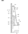
- FIG. 7 It is explanatory drawing which shows the vehicle mounting state of the vehicle display device of 1st Embodiment. It is a perspective view which shows the user side of the display device for a vehicle. It is a perspective view which shows the back side of the display device for a vehicle. It is sectional drawing which shows the IV-IV part in FIG. It is an enlarged sectional view which shows the V part in FIG. It is an exploded perspective view which shows the structure of the display device for a vehicle. It is an enlarged view which shows the VII part in FIG. It is sectional drawing which shows the VIII-VIII part in FIG. 7. It is an exploded perspective view which shows the structure of the display device for a vehicle. It is a perspective view which shows the assembling procedure of a control board.
- the vehicle display device 100 of the first embodiment is shown in FIGS. 1 to 13.
- the vehicle display device 100 of the first embodiment is mounted on a vehicle and is applied to, for example, a car navigation device that displays the position of the own vehicle on a map, guidance information to a desired destination, or the like.
- the vehicle display device 100 can be used for displaying the operating state of various vehicle devices, for example, a car audio device, a car air conditioner device, a vehicle rear side display device, or the like. ..
- the vehicle display device 100 has, for example, an organic EL panel 140 as a self-luminous display unit.
- the display surface 101a of the display main body 101 is in a standing posture.
- the display surface 101a is a surface that extends in the height direction HD and the width direction WD of the vehicle.
- the display surface 101a is positioned in the central region of the WD in the width direction in the vehicle.
- the display surface 101a is positioned inside the dashboard 11 of the vehicle and is exposed on a part of the surface of the dashboard 11.
- the display surface 101a is fitted into the opening 11a formed in the dashboard 11 and is fixed to the vehicle bracket 12 by a clip 154 described later. This mounting form is so-called in-dash mounting. Then, the image displayed on the display main body 101 is visually recognized by the user (for example, the driver).
- the display main body 101 may be covered with liquid LQ by being mounted in-dash.
- the liquid LQ includes, for example, condensed water dripping from the air conditioner component 13 provided in the dashboard 11, a drink accidentally spilled by the user, and the like.
- the air conditioner component 13 includes an air duct and / or a refrigerant pipe.
- the display main body 101 is a self-luminous type, it has a characteristic that heat is easily generated.
- the ECU 14 and the like for other vehicle equipment are also arranged in the dashboard 11, and the environment is such that heat is easily trapped.
- the vehicle rear side RD of the vehicle display device 100 is referred to as a user side US.
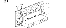
- the vehicle front side FD of the vehicle display device 100 is called a rear side BS.
- the vehicle front side FD is also the traveling direction of the vehicle.
- the Cartesian coordinate system in the vehicle is illustrated.
- the Cartesian coordinate system includes a height direction (vertical direction) HD, a width direction (horizontal direction) WD, and a length direction (front-back direction) LD.
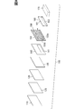
- the vehicle display device 100 includes a display panel 110, a touch panel 130, an organic EL panel 140, a control board 141, a frame 150, a heat conductive member 153, a clip 154, a board cover 160, and heat. It includes a conductive member 163, a communication unit 170, a cooling unit 180, and the like.
- the display main body 101 described above is a portion formed by being laminated mainly by the display panel 110, the touch panel 130, the organic EL panel 140, the frame 150, and the like.
- the display panel 110 is a translucent (transparent) plate-shaped member provided to protect the touch panel 130 and the organic EL panel 140.
- the display panel 110 is formed of, for example, a transparent resin member such as PMMA (polymethyl methacrylate resin) or PC (polycarbonate). Since the display panel 110 has translucency, the image formed by the organic EL panel 140 is transmitted and visually recognized by the user.
- the front shape of the display panel 110 is a horizontally long rectangle.
- a glass material or the like may also be used as the material of the display panel 110.
- the touch panel 130 is an input operation unit for performing an input operation (finger operation) on the car navigation device, and is arranged on the back side BS of the display panel 110.
- the touch panel 130 has a touch panel sensor, a resin cover, and the like.
- the touch panel sensor is formed, for example, by joining transparent capacitance type electrode portions arranged in a matrix shape (mesh shape) to the back surface of a transparent film member.
- the resin cover is a transparent thin-walled resin plate material that protects the touch panel sensor, and is provided on the user side US of the touch panel sensor.
- the touch panel sensor (electrode unit) forms a capacitor between the user's finger and the finger via the resin cover to generate capacitance.
- the touch panel sensor and the resin cover are made of transparent members, the images of various information and the images of various operation icons on the organic EL panel 140 are transparently visible to the user. It has become.
- the touch panel sensor touches the change in capacitance that occurs according to the position of the operated finger when the user brings his or her finger close to any of the various operation icons (for example, about 5 mm) or when the user touches the finger.
- the operation coordinate information is output to the communication unit 170, which will be described later.
- an optical transparent adhesive 125 having light transmission and elasticity is provided between the display panel 110 and the touch panel 130, and the display panel 110 and the touch panel 130 are joined to each other.
- the adhesive instead of the optical transparent adhesive 125, another transparent adhesive having elasticity may be used.
- the organic EL panel 140 displays images of various information (map, vehicle position, destination guidance information image, etc.), images of various operation icons, etc. by emitting light of a plurality of pixels matrix arranged on the display surface. It is a unit and is arranged on the back side BS of the touch panel 130. "EL" of the organic EL panel 140 is an abbreviation for Electroluminescence.
- the organic EL panel 140 is also displayed as an OLED (Organic Light Emitting Diode).
- the organic EL panel 140 is a self-luminous display unit.
- the organic EL panel 140 does not require a backlight like, for example, a liquid crystal panel.
- the thickness dimension of the display main body 101 in the thickness direction THD of FIG. 1 can be set extremely thin.
- the organic EL panel 140 is self-luminous, and the internal heat density increases as it becomes thinner, so that it generates heat to some extent during operation.
- the organic EL panel 140 has flexibility and can be bent or bent.
- the control board 141 controls the display state of the image on the display surface of the organic EL panel 140.
- the control board 141 is connected to the organic EL panel 140 by the flexible wiring 141a.
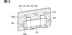
- the control board 141 is inserted into an insertion hole 150e provided in the frame 150, which will be described later, and is fixed to a mounting seat formed on the back side BS of the frame 150 (FIGS. 11 and 12).
- the control board 141 is also a member that generates heat, like the organic EL panel 140.
- an optical transparent adhesive 135 having light transmission and elasticity is provided between the touch panel 130 and the organic EL panel 140, and the touch panel 130 and the organic EL panel 140 are joined to each other.
- the adhesive instead of the optical transparent adhesive 135, another transparent adhesive having elasticity may be used.
- optical transparent adhesive 125 and touch panel 130 may be abolished in the vehicle display device 100 that does not require finger operation.
- the organic EL panel 140 is bonded to the display panel 110 by the optical transparent adhesive 135.
- the frame 150 is a metal member arranged on the back side BS of the organic EL panel 140.
- the frame 150 is a skeleton member for obtaining the rigidity of the thinned display main body 101. Further, since the frame 150 is made of a metal member, it also serves as a heat sink for the organic EL panel 140.
- the frame 150 is, for example, a metal molded product formed by die-casting using an alloy of aluminum and magnesium as a material. As shown in FIGS. 7 and 8, the frame 150 has a frame-shaped outer peripheral portion 150a that covers the outer periphery of the organic EL panel 140, and an outer peripheral wall portion 150b that is connected from the outer peripheral portion 150a and is formed inward with a predetermined width. , And an inner side wall portion 150c formed so as to be recessed from the outer peripheral wall portion 150b to the back surface side BS in a stepped manner.
- the outer peripheral portion 150a is a portion that can be visually recognized from the opening 11a of the dashboard 11, and for example, a coating for decoration is partially provided in the region shown by the broken line in FIG.
- the design is improved by this painting. It is not necessary to paint the entire frame 150, and by applying such partial painting, the cost can be suppressed.
- a narrow elastic adhesive 151 (or a liquid adhesive) having a cushioning property is provided on the user-side US surface of the outer peripheral wall portion 150b, and the outer peripheral portion of the BS on the back side of the display panel 110 is formed. It is joined to the outer peripheral wall portion 150b.
- a narrow elastic adhesive 152 (or a liquid adhesive) having a cushioning property is provided around the inner side wall portion 150c (four sides), and the outer peripheral portion of the back side BS of the organic EL panel 140 is provided. Is joined to the user-side US surface of the frame 150.
- the elastic adhesive 152 may be set as necessary and may be abolished.
- a reinforcing rib 150d projecting to the back side BS is formed so that the rigidity of the frame 150 itself can be increased. Further, by forming the reinforcing rib 150d on the frame 150, the surface area of the frame 150 is expanded, and the heat dissipation when functioning as a heat sink can be improved.
- An elongated insertion hole 150e extending along the lower side of the frame 150 is provided on the lower end side of the frame 150, and a plurality of mounting seats for fixing the control board 141 are provided on the back surface of the frame 150. There is. As described above, the control substrate 141 in the organic EL panel 140 is inserted into the insertion hole 150e and fixed to the back side BS of the frame 150.
- the thermal conductive member 153 is arranged between the organic EL panel 140 and the frame 150 in an inner region surrounded by the elastic adhesive 152 (four sides), and heat generated by the organic EL panel 140 is transferred to the frame 150 side. It is a member that efficiently conveys information.
- the thermal conductive member 153 is formed of a gel-like or sheet-like member, and the elastic adhesive 152 absorbs the variation in the dimensions in the thickness direction so that the organic EL panel 140 and the frame 150 face each other. It is designed to make sure contact with the surface.
- the heat conductive member 153 corresponds to the heat conductive member for the display portion of the present disclosure.
- Clips 154 are fixing members for fixing the vehicle display device 100 to the vehicle bracket 12, and are provided on a plurality of BSs on the back side of the frame 150.
- the clip 154 is made of resin, for example, and one end side is one-touch assembled to a mounting seat (for example, a mounting hole) formed in the frame 150. Then, the vehicle display device 100 is inserted from the opening 11a of the dashboard 11 toward the front side of the vehicle, so that the other end side of the clip 154 is one-touch assembled to the vehicle bracket 12.
- One end side of the clip 154 is not limited to one that is one-touch assembled to the frame 150, and may be fixed by screwing with screws or the like.
- a heat conductive material or a heat insulating material between the control board 141 and the frame 150 in consideration of the heat balance between the control board 141 and the frame 150. For example, if the heat of the control board 141 should be conducted to the frame 150, a heat conductive material is interposed, and if the heat of the control board 141 should not be conducted to the frame 150, a heat insulating material is interposed. You can use it properly.
- the substrate cover 160 is a metal member (for example, aluminum, magnesium, etc.) that covers the entire control substrate 141, forms a flat box shape with respect to the vehicle traveling direction, and is provided on the outer peripheral portion. It is fixed to the mounting seat formed on the back side BS of the frame 150 by the mounting portion 161. An opening 162 into which one end side of the communication unit 170, which will be described later, is inserted is formed in the lower region of the surface of the BS on the back side of the board cover 160.
- a metal member for example, aluminum, magnesium, etc.
- a labyrinth for suppressing the infiltration of liquid LQ into the inside of the substrate cover is provided between the substrate cover 160 and the frame 150 and between the substrate cover 160 and the communication unit 170.
- a structure LBY is formed.
- the thermal conductive member 163 is arranged in the upper region of the opening 162 between the control board 141 and the board cover 160, and serves as a member that efficiently transfers the heat generated by the control board 141 to the board cover 160 side. There is.
- the thermal conductive member 163 is formed of a gel-like or sheet-like member so as to be surely in contact with the surfaces of the control substrate 141 and the substrate cover 160 facing each other.
- the heat conductive member 163 corresponds to the heat conductive member for a substrate of the present disclosure.
- the communication unit 170 has a flat box shape in the vertical direction and is a unit that communicates with the ECU of other devices mounted on the vehicle, and is via an opening 162 on the lower side of the board cover 160. Is connected to the control board 141.
- the cooling unit 180 is a heat transfer means (in other words, a cooling means for cooling the frame 150) that releases the heat of the frame 150 (heat of the organic EL panel 140) to the outside, and for example, a heat pipe is used.
- the cooling unit 180 has, for example, a pipe member having a flat cross section and an L-shaped overall shape in which the inside is evacuated and a refrigerant is sealed inside.
- One end side of the cooling unit 180 is interposed between the frame 150 and the control board 141 and is in contact with the frame 150. Further, the other end side of the cooling unit 180 extends to the back side BS and is arranged in a region suitable for releasing heat. The position on the other end side can be set, for example, in the outer region of the communication unit 170, or in the inner region of the communication unit 170 when there is a cooling fan in the communication unit 170.
- the component mounting area including the air conditioner component 13 and the ECU 14 of other vehicle equipment is behind the display main body 101.
- the cooling unit 180 includes a fan that utilizes the heat dissipation path indicated by the arrow AR.
- the arrow VV indicates the flow path of the liquid LQ.
- the liquid LQ flows on the back surface of the frame 150, the back surface of the substrate cover 160, and the back surface of the communication unit 170.
- the labyrinth structure LBY is located between those parts.
- the labyrinth structure LBY is formed by contact of members and members facing each other through a narrow gap.
- the labyrinth structure LBY suppresses the infiltration of the liquid LQ by causing a high pressure loss with respect to the liquid LQ.
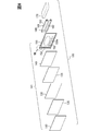
- FIG. 10 is an exploded view of the plate-shaped unit 15 including the organic EL panel 140 and the frame 150.
- FIG. 11 shows an assembly process of the plate-shaped unit 15.
- the control board 141 is temporarily tilted as shown by arrow XI-1 by extending the flexible wiring 141a from the bent state.
- the control board 141 is inserted into the insertion hole 150e and arranged through the insertion hole 150e as shown by the arrow XI-2 in the tilted state. Further, the control board 141 is triggered by bending the flexible wiring 141a again, as shown by arrow XI-3. After this, the control board 141 is placed and fixed behind the frame 150.
- the heat pipe of the cooling unit 180 is positioned between the frame 150 and the control board 141.
- the substrate cover 160 is covered, and the communication unit 170 is connected and fixed.
- the configuration of the vehicle display device 100 of the present embodiment is as described above, and its operation and effect will be described below.
- the light emitting state of each pixel on the display surface of the organic EL panel 140 is controlled by the control board 141, and a predetermined image (map, own vehicle) is controlled.
- a predetermined image maps, own vehicle
- the position, destination guidance information image, images of various operation icons, etc.) are displayed.
- the user can receive driving assistance (navigation) based on the displayed image.
- the user can change the display state of the image (enlarge / reduce the map) or display the destination guidance information (guidance on) by finger-operating the images of various operation icons.
- the self-luminous organic EL panel 140 generates heat and is accompanied by a temperature rise.
- the organic EL panel 140 which does not require a backlight, is made thinner, but has a higher internal heat density and a higher degree of temperature rise.
- the frame 150 is made of metal, and the heat conductive member 153 is interposed between the organic EL panel 140 and the frame 150.
- the heat generated by the organic EL panel 140 can be effectively transferred to the frame 150 side via the heat conductive member 153, and further discharged to the outside (inside the dashboard 11).
- the metal frame 150 can function as a heat sink. Therefore, in the vehicle display device 100 mounted on the in-dash, the heat generated from the organic EL panel 140 can be effectively released, and the temperature rise of the organic EL panel 140 can be suppressed.
- the frame 150 is provided with a cooling unit 180 (heat pipe) that releases the heat of the frame 150 to the outside.
- the cooling unit 180 can further and effectively release the heat of the organic EL panel 140 to the outside through the frame 150.
- the vehicle display device 100 is mounted on the in-dash, it is possible to be exposed to water by, for example, condensed water dripping from the air conditioner pipe 13 arranged in the dashboard 11 or a drink accidentally spilled by the user. Has sex.
- the substrate cover 160 that covers the control substrate 141 is provided, it is possible to suppress water splashing on the control substrate 141 and improve the water resistance in the dashboard 11.
- the heat conductive member 163 is interposed between the control board 141 and the board cover 160, the heat generated by the control board 141 is transferred from the board cover 160 to the outside via the heat conductive member 163. It can be released effectively.
- the substrate cover 160 has a function of suppressing the temperature rise in addition to the function of improving the water resistance of the control substrate 141.
- the board cover 160 is made of metal, it is possible to improve the above heat dissipation and shield the electrical noise generated from the control board 141. That is, the board cover 160 can also be used as a shield case.
- the frame 150 is provided with a clip 154.
- the vehicle display device 100 can be inserted straight from the opening 11a of the dashboard 11 toward the front side of the vehicle, and can be assembled to the vehicle bracket 12 with one touch by the clip 154, which facilitates positioning and improves the ease of assembly.
- the frame 150 is made of metal, the rigidity of the frame 150 can be made higher than that of a resin one, for example. Therefore, the overall rigidity of the vehicle display device 100, which is thinned by adopting the organic EL panel 140, can be increased. For example, it is possible to secure the strength when assembling the vehicle display device 100 to the vehicle or when removing the vehicle display device 100 as described above. Further, the touch panel 130 is not distorted when the touch panel 130 is touched.
- the frame 150 is, for example, a metal molded product by die casting.
- the outer peripheral portion 150a, the outer peripheral wall portion 150b, the inner side wall portion 150c, the reinforcing rib 150d, and the mounting seat for the control board 141, the clip 154, and the board cover 160 Etc. can be easily molded.
- the organic EL panel 140 is formed into a curved surface, by using the frame 150 as a metal molded product, it is easy to deal with the same curved surface formation, and the vehicle is excellent in visibility and design. It can be the display device 100.
- the vehicle display device 100A of the second embodiment is shown in FIGS. 14 to 16.
- the cooling unit 180 is changed to the cooling unit 180A with respect to the first embodiment.
- the cooling unit 180A has a duct 181 and a fan 182, and is a cooling fan for cooling the frame 150 and the substrate cover 160.
- the duct 181 covers a part of the back side BS of the frame 150 and the substrate cover 160, and is an air guiding member extending to the back side BS on the upper side of the communication unit 170.
- One or more introduction holes for introducing air are provided on the upper side of the duct 181.
- the fan 182 is arranged between the communication unit 170 and the duct 181 by using, for example, a sirocco fan whose axial thickness dimension is set smaller than the radial dimension.
- a plurality of heat radiation fins 150f that are integrally provided with the frame 150 and project in a plate shape are formed.
- a plurality of heat radiation fins 160a are integrally provided with the substrate cover 160 and project in a plate shape.
- the power supply for the cooling unit 180A is supplied from, for example, the control board 141 or the communication unit 170.
- the inlet 181a for the cooling air is partitioned by the duct 181 that provides the cooling unit 180A.
- the entrance 181a opens at the top of the duct 181.
- the cooling air flows into the inside of the duct 181 from the upper part of the duct 181 by the fan 182, passes through the frame 150, the heat radiation fin 150f, the substrate cover 160, the heat radiation fin 160a, and the fan 182, and passes through the back side BS of the duct 181. Is discharged from.
- the heat of the organic EL panel 140 can be effectively released to the outside by the cooling air generated by the operation of the cooling unit 180A, the frame 150, and the heat radiation fins 150f.
- the heat of the control board 141 can be effectively released to the outside by the cooling air generated by the operation of the cooling unit 180A, the board cover 160, and the heat radiation fins 160a.
- the substrate cover 160 is made of metal, but may be made of resin instead.
- the clip 154 is provided on the frame 150 for assembling the vehicle display devices 100 and 100A to the vehicle bracket 12, the clip 154 may be replaced with a mounting portion or the like extending from the frame 150. ..
- the painting on the outer peripheral portion 150a of the frame 150 and the cooling units 180 and 180A may be abolished.
- the organic EL panel 140 has been described as a typical example as the self-luminous display unit, but the present invention is not limited to this, and is applied to other fluorescent display tubes, inorganic EL displays, and the like. May be good.
- disclosure in this specification, drawings, etc. is not limited to the illustrated embodiment.
- the disclosure includes exemplary embodiments and modifications by those skilled in the art based on them.
- disclosure is not limited to the parts and / or element combinations shown in the embodiments. Disclosure can be carried out in various combinations. Disclosures can have additional parts that can be added to the embodiments.
- the disclosure includes the parts and / or elements of the embodiment omitted. Disclosures include the replacement or combination of parts and / or elements between one embodiment and the other.
- the technical scope disclosed is not limited to the description of the embodiments.
Landscapes
- Engineering & Computer Science (AREA)
- Chemical & Material Sciences (AREA)
- Combustion & Propulsion (AREA)
- Transportation (AREA)
- Mechanical Engineering (AREA)
- Physics & Mathematics (AREA)
- General Physics & Mathematics (AREA)
- Thermal Sciences (AREA)
- Microelectronics & Electronic Packaging (AREA)
- Instrument Panels (AREA)
- Casings For Electric Apparatus (AREA)
- Cooling Or The Like Of Electrical Apparatus (AREA)
- Electroluminescent Light Sources (AREA)
- Devices For Indicating Variable Information By Combining Individual Elements (AREA)
Applications Claiming Priority (2)
| Application Number | Priority Date | Filing Date | Title |
|---|---|---|---|
| JP2019-075083 | 2019-04-10 | ||
| JP2019075083A JP7028216B2 (ja) | 2019-04-10 | 2019-04-10 | 車両用表示装置 |
Publications (1)
| Publication Number | Publication Date |
|---|---|
| WO2020208948A1 true WO2020208948A1 (ja) | 2020-10-15 |
Family
ID=72751967
Family Applications (1)
| Application Number | Title | Priority Date | Filing Date |
|---|---|---|---|
| PCT/JP2020/006716 Ceased WO2020208948A1 (ja) | 2019-04-10 | 2020-02-20 | 車両用表示装置 |
Country Status (2)
| Country | Link |
|---|---|
| JP (1) | JP7028216B2 (https=) |
| WO (1) | WO2020208948A1 (https=) |
Citations (8)
| Publication number | Priority date | Publication date | Assignee | Title |
|---|---|---|---|---|
| JP2005308862A (ja) * | 2004-04-19 | 2005-11-04 | Auto Network Gijutsu Kenkyusho:Kk | 有機el表示装置およびセンタークラスタユニット |
| JP2014101052A (ja) * | 2012-11-21 | 2014-06-05 | Fujitsu Ten Ltd | 車載装置、及び、取付装置 |
| JP2015049410A (ja) * | 2013-09-03 | 2015-03-16 | 住友電装株式会社 | 表示装置 |
| JP2016109728A (ja) * | 2014-12-02 | 2016-06-20 | 旭硝子株式会社 | 電子デバイス樹脂一体成形品 |
| JP2018018842A (ja) * | 2016-07-25 | 2018-02-01 | 日本精機株式会社 | 放熱構造及び表示装置 |
| JP2018031964A (ja) * | 2016-08-26 | 2018-03-01 | キヤノン株式会社 | 表示装置 |
| WO2019012689A1 (ja) * | 2017-07-14 | 2019-01-17 | 三菱電機株式会社 | 車載用表示装置及び意匠部材 |
| JP2019008225A (ja) * | 2017-06-27 | 2019-01-17 | 株式会社デンソーテン | 表示装置 |
-
2019
- 2019-04-10 JP JP2019075083A patent/JP7028216B2/ja active Active
-
2020
- 2020-02-20 WO PCT/JP2020/006716 patent/WO2020208948A1/ja not_active Ceased
Patent Citations (8)
| Publication number | Priority date | Publication date | Assignee | Title |
|---|---|---|---|---|
| JP2005308862A (ja) * | 2004-04-19 | 2005-11-04 | Auto Network Gijutsu Kenkyusho:Kk | 有機el表示装置およびセンタークラスタユニット |
| JP2014101052A (ja) * | 2012-11-21 | 2014-06-05 | Fujitsu Ten Ltd | 車載装置、及び、取付装置 |
| JP2015049410A (ja) * | 2013-09-03 | 2015-03-16 | 住友電装株式会社 | 表示装置 |
| JP2016109728A (ja) * | 2014-12-02 | 2016-06-20 | 旭硝子株式会社 | 電子デバイス樹脂一体成形品 |
| JP2018018842A (ja) * | 2016-07-25 | 2018-02-01 | 日本精機株式会社 | 放熱構造及び表示装置 |
| JP2018031964A (ja) * | 2016-08-26 | 2018-03-01 | キヤノン株式会社 | 表示装置 |
| JP2019008225A (ja) * | 2017-06-27 | 2019-01-17 | 株式会社デンソーテン | 表示装置 |
| WO2019012689A1 (ja) * | 2017-07-14 | 2019-01-17 | 三菱電機株式会社 | 車載用表示装置及び意匠部材 |
Also Published As
| Publication number | Publication date |
|---|---|
| JP7028216B2 (ja) | 2022-03-02 |
| JP2020172179A (ja) | 2020-10-22 |
Similar Documents
| Publication | Publication Date | Title |
|---|---|---|
| US20060209502A1 (en) | Display apparatus | |
| US10598974B2 (en) | On-vehicle display device | |
| KR20190052386A (ko) | 차량용 인스트루먼트 패널 | |
| CN203204952U (zh) | 显示装置和电视 | |
| WO2019130756A1 (ja) | 表示装置 | |
| JP7036074B2 (ja) | 車両用表示装置 | |
| WO2022185770A1 (ja) | 表示装置 | |
| JP7028216B2 (ja) | 車両用表示装置 | |
| WO2014178175A1 (ja) | 車載用表示装置 | |
| JP2016058537A (ja) | 電子機器 | |
| WO2022185769A1 (ja) | 表示装置 | |
| JP7474028B2 (ja) | ヘッドアップディスプレイ | |
| JP2005024961A (ja) | 電気光学装置及び電子機器 | |
| JP2009079993A (ja) | 表示装置 | |
| JP2016179715A (ja) | 車両用表示装置 | |
| JP7463871B2 (ja) | 表示装置 | |
| JP7395854B2 (ja) | 表示装置 | |
| JP2005181640A (ja) | 表示装置 | |
| JP2010006196A (ja) | 発光表示装置 | |
| JP2023003233A (ja) | 表示装置 | |
| JP2017096799A (ja) | 表示装置 | |
| JP7276234B2 (ja) | 表示装置および表示装置の製造方法 | |
| US7881056B2 (en) | Heat radiation structure for an electronic device | |
| JP2022135389A (ja) | 表示装置 | |
| JP2009014833A (ja) | 平面型表示機器 |
Legal Events
| Date | Code | Title | Description |
|---|---|---|---|
| 121 | Ep: the epo has been informed by wipo that ep was designated in this application |
Ref document number: 20788357 Country of ref document: EP Kind code of ref document: A1 |
|
| NENP | Non-entry into the national phase |
Ref country code: DE |
|
| 122 | Ep: pct application non-entry in european phase |
Ref document number: 20788357 Country of ref document: EP Kind code of ref document: A1 |