WO2020203280A1 - 排熱回収システム - Google Patents
排熱回収システム Download PDFInfo
- Publication number
- WO2020203280A1 WO2020203280A1 PCT/JP2020/011901 JP2020011901W WO2020203280A1 WO 2020203280 A1 WO2020203280 A1 WO 2020203280A1 JP 2020011901 W JP2020011901 W JP 2020011901W WO 2020203280 A1 WO2020203280 A1 WO 2020203280A1
- Authority
- WO
- WIPO (PCT)
- Prior art keywords
- exhaust gas
- aqc
- damper
- command
- thermometer
- Prior art date
- Legal status (The legal status is an assumption and is not a legal conclusion. Google has not performed a legal analysis and makes no representation as to the accuracy of the status listed.)
- Ceased
Links
Images
Classifications
-
- C—CHEMISTRY; METALLURGY
- C04—CEMENTS; CONCRETE; ARTIFICIAL STONE; CERAMICS; REFRACTORIES
- C04B—LIME, MAGNESIA; SLAG; CEMENTS; COMPOSITIONS THEREOF, e.g. MORTARS, CONCRETE OR LIKE BUILDING MATERIALS; ARTIFICIAL STONE; CERAMICS; REFRACTORIES; TREATMENT OF NATURAL STONE
- C04B7/00—Hydraulic cements
- C04B7/36—Manufacture of hydraulic cements in general
- C04B7/43—Heat treatment, e.g. precalcining, burning, melting; Cooling
- C04B7/47—Cooling ; Waste heat management
- C04B7/475—Cooling ; Waste heat management using the waste heat, e.g. of the cooled clinker, in an other way than by simple heat exchange in the cement production line, e.g. for generating steam
-
- C—CHEMISTRY; METALLURGY
- C04—CEMENTS; CONCRETE; ARTIFICIAL STONE; CERAMICS; REFRACTORIES
- C04B—LIME, MAGNESIA; SLAG; CEMENTS; COMPOSITIONS THEREOF, e.g. MORTARS, CONCRETE OR LIKE BUILDING MATERIALS; ARTIFICIAL STONE; CERAMICS; REFRACTORIES; TREATMENT OF NATURAL STONE
- C04B7/00—Hydraulic cements
- C04B7/36—Manufacture of hydraulic cements in general
- C04B7/43—Heat treatment, e.g. precalcining, burning, melting; Cooling
- C04B7/44—Burning; Melting
-
- C—CHEMISTRY; METALLURGY
- C04—CEMENTS; CONCRETE; ARTIFICIAL STONE; CERAMICS; REFRACTORIES
- C04B—LIME, MAGNESIA; SLAG; CEMENTS; COMPOSITIONS THEREOF, e.g. MORTARS, CONCRETE OR LIKE BUILDING MATERIALS; ARTIFICIAL STONE; CERAMICS; REFRACTORIES; TREATMENT OF NATURAL STONE
- C04B7/00—Hydraulic cements
- C04B7/36—Manufacture of hydraulic cements in general
- C04B7/43—Heat treatment, e.g. precalcining, burning, melting; Cooling
- C04B7/47—Cooling ; Waste heat management
-
- Y—GENERAL TAGGING OF NEW TECHNOLOGICAL DEVELOPMENTS; GENERAL TAGGING OF CROSS-SECTIONAL TECHNOLOGIES SPANNING OVER SEVERAL SECTIONS OF THE IPC; TECHNICAL SUBJECTS COVERED BY FORMER USPC CROSS-REFERENCE ART COLLECTIONS [XRACs] AND DIGESTS
- Y02—TECHNOLOGIES OR APPLICATIONS FOR MITIGATION OR ADAPTATION AGAINST CLIMATE CHANGE
- Y02P—CLIMATE CHANGE MITIGATION TECHNOLOGIES IN THE PRODUCTION OR PROCESSING OF GOODS
- Y02P10/00—Technologies related to metal processing
- Y02P10/25—Process efficiency
Definitions
- the present invention relates to an exhaust heat recovery system that recovers heat from exhaust gas in a cement manufacturing process.
- the cement manufacturing process is roughly divided into a raw material process of drying, crushing, and blending cement raw materials, a firing process of firing clinker, which is an intermediate product from raw materials, and a finishing process of adding clinker to clinker and crushing it to make cement. Consists of.
- the cement raw material is first preheated in a preheater, then calcined in a calcining furnace, then fired in a kiln furnace, and finally an air quenching cooler (hereinafter, “AQC”). It is cooled by.
- AQC air quenching cooler
- AQC air quenching cooler
- AQC air quenching cooler
- AQC air quenching cooler
- a large amount of exhaust gas at 250 to 300 ° C. is generated.
- an exhaust heat recovery system has been known in which exhaust gas generated by AQC is introduced into a boiler to recover exhaust heat, and the recovered heat is used to generate electricity.
- FIG. 3 of Patent Document 1 discloses an exhaust heat recovery system including a high-temperature exhaust gas line connected to a high-temperature portion of AQC and a low-temperature exhaust gas line connected to a low-temperature portion of AQC.
- the high temperature exhaust gas line discharges a relatively high temperature (for example, 360 ° C. on average) exhaust gas in the AQC
- the low temperature exhaust gas line discharges a relatively low temperature (for example, 110 ° C. on average) exhaust gas in the AQC.
- the exhaust gas discharged from the AQC through the high temperature exhaust gas line is guided to the boiler.
- superheated steam is generated by the heat of exhaust gas, and the superheated steam is used for power generation in a steam turbine generator.
- the exhaust gas whose heat has been recovered by the boiler merges with the exhaust gas discharged from the AQC by the low-temperature exhaust gas line, passes through the dust collector, and is discharged to the atmosphere from the chimney.
- the amount of clinker supplied to the AQC has a fluctuation range, and as a result, the temperature of the exhaust gas generated in the AQC fluctuates. Since such temperature fluctuations of the exhaust gas in the AQC affect the increase and decrease of the heat recovered by the boiler, a system capable of efficiently recovering the heat without depending on the temperature fluctuations in the AQC is desired.
- an object of the present invention is to provide an exhaust heat recovery system capable of efficiently recovering heat with an AQC boiler even when the temperature of the exhaust gas in the AQC fluctuates.
- the exhaust heat recovery system includes a kiln for firing a cement raw material and an air quenching cooler for rapidly cooling while transporting a calcined product charged from the kiln (hereinafter referred to as an air quenching cooler).
- AQC air quenching cooler
- an exhaust heat recovery system that recovers heat from the exhaust gas generated by the AQC
- a boiler that recovers heat from the exhaust gas generated by the AQC
- a predetermined high temperature of the AQC a predetermined high temperature of the AQC.
- a first exhaust gas line that guides the exhaust gas discharged from the unit to the inlet of the boiler, a discharge facility that discharges the exhaust gas after heat is recovered by the boiler to the atmosphere, and a discharge facility that discharges the exhaust gas discharged from the outlet of the boiler.
- the second exhaust gas line for merging the exhaust gas discharged from the low temperature part of the AQC located on the downstream side of the high temperature part in the direction of transporting the fired product to the discharge line, and the first exhaust gas line.
- the provided thermometer, at least one flow rate adjusting device for adjusting the flow rate of the exhaust gas flowing through at least one of the first exhaust gas line and the second exhaust gas line, and the measured value of the thermometer are brought close to a predetermined set value.
- a command generation device for generating a command value for adjusting the at least one flow control device is provided.
- the temperature of the gas flowing into the boiler is kept constant by adjusting at least one flow rate adjusting device according to the command value generated by the command generating device. Can be kept at (that is, at the set value). As a result, even when the temperature of the exhaust gas in the AQC fluctuates, the heat can be efficiently recovered by the boiler.
- the command generator when the measured value is higher than the set value, the command generator generates at least the command value for reducing the flow rate of the exhaust gas flowing through the second exhaust gas line, and the measured value is the said. If it is lower than the set value, at least the command value for increasing the flow rate of the exhaust gas flowing through the second exhaust gas line may be generated.
- the command generator controls the at least one flow rate adjusting device based on the generated command value.
- the above system is generated by an operation device that receives an operator's operation and generates an operation command, a control device that controls at least one flow rate control device based on the operation command, and the command generation device.
- An output device for outputting an operation instruction corresponding to the command value is further provided.
- the above system is provided in an introduction line connected to the first exhaust gas line and introducing a low-temperature gas having a temperature lower than the exhaust gas discharged from the high-temperature portion of the AQC into the first exhaust gas line, and the introduction line.
- the command generator further comprises a command value for maintaining the closed state when the measured value of the thermometer is equal to or lower than a predetermined threshold value higher than the set value.
- a command value for opening the opening / closing device may be generated. According to this configuration, by adjusting the third damper according to the generated opening degree command, it is possible to prevent gas exceeding the allowable temperature from flowing into the boiler.
- thermometer is a first thermometer
- a second thermometer is provided on the upstream side in the direction of transporting the fired product from the high temperature portion in the AQC
- the command generator is provided. May predict the temperature of the exhaust gas at the inlet of the boiler after a lapse of a predetermined time from the present time based on the measured value of the second thermometer.
- an exhaust heat recovery system capable of efficiently recovering heat with a boiler even when the temperature of the exhaust gas in the AQC fluctuates.
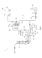
- FIG. 1 is a diagram showing a schematic configuration of a cement firing plant including an exhaust heat recovery system according to an embodiment of the present invention.
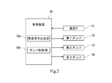
- FIG. 2 is a block diagram of damper control in the exhaust heat recovery system shown in FIG.
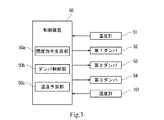
- FIG. 3 is a block diagram of damper control in the exhaust heat recovery system according to the first modification.
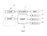
- FIG. 4 is a block diagram of damper control in the exhaust heat recovery system according to the second modification.
- FIG. 1 is a diagram showing a schematic configuration of a cement firing facility 1 including an exhaust heat recovery system 2 according to the present embodiment.
- cement firing equipment As mentioned above, the cement manufacturing process consists of a raw material process, a firing process and a finishing process.
- the cement firing facility 1 shown in FIG. 1 is responsible for the firing process, and is a powder raw material obtained by drying, crushing, and blending limestone, clay, etc. in the raw material process (hereinafter referred to as “cement raw material”). .), It is a facility to bake the intermediate product, clinker.
- the cement firing facility 1 includes a preheater 11, a calcining furnace 12, a rotary kiln 13, and an AQC 14.
- the preheater 11 includes a plurality of stages of cyclones connected in series. In the preheater 11, the exhaust heat from the rotary kiln 13 moves in order from the lowest cyclone to the uppermost cyclone, and the cement raw material moves in order from the uppermost cyclone to the lowest cyclone. The lowermost cyclone of the preheater 11 is connected to the calcining furnace 12.
- the cement raw material from the preheater 11 is calcified in an atmosphere of about 900 ° C.
- the calcining furnace 12 is connected to an air extraction line 12a for a calcining furnace that sends exhaust heat from the AQC 14 to the calcining furnace 12 and a fuel supply line 12b that supplies fuel or the like to the calcining furnace 12.
- the outlet of the calcining furnace 12 is connected to the inlet of the rotary kiln 13.
- the rotary kiln 13 is a horizontally long cylindrical rotary kiln, and is installed with a slight downward slope from the raw material inlet to the raw material outlet.
- the cement raw material preheated and calcined in the preheater 11 and the calcining furnace 12 is fired by the exhaust heat of the AQC 14 and the combustion gas of the burner 100.
- the exit of the rotary kiln 13 is connected to the inlet 14a of the AQC14.
- the high-temperature (for example, about 1400 ° C.) fired product from the rotary kiln 13 is rapidly cooled.
- the fired product dropped into the AQC14 from the outlet of the rotary kiln 13 is conveyed toward the outlet 14b by a conveyor (not shown) in the AQC14.
- the fired product is cooled by blowing cooling air from below the conveyor while it is being conveyed by the conveyor.
- the fired product cooled by AQC14 that is, the clinker, is sent to the clinker silo by a clinker conveyor (not shown) after exiting from the outlet 14b.
- the cooling air blown onto the high-temperature fired product in the AQC14 becomes high-temperature exhaust gas.
- the gas temperature in the AQC 14 forms a distribution that decreases as it approaches the outlet 14b along the transport direction of the fired product.
- the gas temperature near the inlet 14a of the AQC14 is about 1350 ° C
- the gas temperature near the outlet 14b of the AQC14 is about 100 ° C.
- the temperature of the exhaust gas in the AQC14 fluctuates.
- the cement firing facility 1 further includes an exhaust heat recovery system 2 that recovers heat from the exhaust gas of the high temperature portion 14c of the AQC 14 and the exhaust gas generated by the preheater 11.
- the exhaust heat recovery system 2 includes an air quenching cooler boiler (hereinafter, AQC boiler) 30, a control device 50, and a steam turbine generator 60.
- the AQC boiler 30 is a boiler that uses the exhaust gas generated in the AQC 14 as a heating medium.
- the AQC boiler 30 includes a boiler body 31 having a gas inlet 31a and a gas outlet 31b.
- a superheater 32, an evaporator 33, and a preheater (economizer) 34, which are heat exchangers, are installed in the boiler main body 31 in this order from the gas inlet 31a toward the gas outlet 31b.
- a steam drum 35 is attached to the boiler main body 31.
- the first exhaust gas line 43 extending from the high temperature portion 14c of the AQC14 is connected to the gas inlet 31a of the boiler main body 31.
- the high temperature portion 14c of the AQC14 is a portion where the exhaust gas temperature in the AQC14 is relatively high (for example, about 350 ° C.).
- the average temperature of the high temperature portion 14c of the AQC 14 is within the allowable temperature range of the AQC boiler 30.
- the AQC14 is connected to the above-mentioned extraction line 12a for a calcining furnace.
- the bleeding line 12a for the calcining furnace is connected to the AQC14 on the upstream side in the transport direction of the fired product from the connection position between the first exhaust gas line 43 and the AQC14. Therefore, the exhaust gas having a temperature higher than the temperature of the exhaust gas discharged from the first exhaust gas line 43 (for example, about 600 ° C.) is extracted from the bleeding furnace line 12a.
- thermometer 101 (corresponding to the "second thermometer” of the present invention) is provided on the upstream side in the transport direction of the fired product with respect to the high temperature portion 14c in the AQC14. The measured value of the thermometer 101 is sent to the control device 50.
- a second discharge line 44 (corresponding to the "release line” of the present invention) is connected to the gas outlet 31b of the boiler main body 31.
- the second discharge line 44 is provided with a dust collector 36, a blower 37, and a chimney 38 (corresponding to the “discharge equipment” of the present invention) in this order from the upstream to the downstream of the exhaust gas flow.
- the exhaust gas after heat exchange in the AQC boiler 30 passes through the dust collector 36 and is discharged to the atmosphere from the chimney 38.
- the second exhaust gas line 45 extends from the low temperature portion 14d of the AQC14.
- the low temperature portion 14d of the AQC14 is a portion where the exhaust gas temperature in the AQC14 is relatively low (for example, about 150 ° C.), and is located downstream of the high temperature portion 14c in the AQC14 in the direction of transporting the fired product.
- the upstream end of the second exhaust gas line 45 is located at the low temperature portion 14d of the AQC14, relatively low temperature exhaust gas is discharged from the AQC14 through the second exhaust gas line 45.
- the downstream end of the second exhaust gas line 45 is connected between the AQC boiler 30 and the dust collector 36 in the second discharge line 44.
- the exhaust gas discharged from the low temperature portion 14d of the AQC 14 passes through the second exhaust gas line 45, merges with the exhaust gas emitted from the outlet 31b of the AQC boiler 30, then passes through the dust collector 36, and is discharged to the atmosphere from the chimney 38. Will be done.
- the first exhaust gas line 43 is provided with a thermometer 51 (corresponding to the "thermometer” and "first thermometer” of the present invention) for measuring the exhaust gas temperature guided to the AQC boiler 30. Further, a first damper 52 is provided on the upstream side of the thermometer 51 in the first exhaust gas line 43. Further, the second exhaust gas line 45 is provided with a second damper 53. Further, an introduction line 46 is connected between the first damper 52 and the thermometer 51 in the first exhaust gas line 43. The introduction line 46 is provided with a third damper 54. In the present embodiment, the first damper 52, the second damper 53, and the third damper 54 are controlled by the control device 50 to adjust the opening degree. The details of the control method by the control device 50 will be described later.
- the steam turbine generator 60 includes a steam turbine 61 and a generator 62.
- the steam turbine 61 is driven by the supplied steam.
- the control device 50 controls the first damper 52, the second damper 53, and the third damper 54 based on the temperature measured by the thermometer 51.
- FIG. 2 shows a block diagram of damper control in the exhaust heat recovery system 2.
- the control device 50 includes a processor and volatile and non-volatile memories.
- the processor is composed of a CPU, an MPU, a GPU, and the like, and by reading and executing various programs stored in the memory, control according to a control target and various functional units as described later are realized.
- FIG. 2 shows the functional configuration of the control device 50.
- the control device 50 includes an opening command generation unit 50a and a damper control unit 50b, and these functional units 50a and 50b are constructed by combining hardware such as the CPU and software stored in the ROM or the like. ..
- the control device 50 does not have to be composed of one unit, and may be composed of a plurality of units.
- the opening command generation unit 50a generates an opening command value which is opening information of the first damper 52, the second damper 53, and the third damper 54 based on the measured value of the thermometer 51.
- the damper control unit 50b controls the first damper 52, the second damper 53, and the third damper 54 based on the opening degree command generated by the opening degree command generation unit 50a.
- the control device 50 controls at least one of the first damper 52 and the second damper 53 so that the temperature of the exhaust gas guided to the AQC boiler 30 is maintained at a predetermined temperature.
- the opening command generation unit 50a adjusts at least one of the first damper 52 and the second damper 53 so that the measured value T of the thermometer 51 approaches a predetermined set value T1 (command value ( Opening command value) is generated. That is, the control device 50 functions as the "command generator" of the present invention.
- the predetermined set value T1 is set to a value equal to or less than the allowable upper limit value (for example, 400 ° C.) of the AQC boiler 30 and as close as possible to the allowable upper limit value (for example, 360 ° C.) so that the heat of the exhaust gas in the AQC 14 can be recovered as much as possible. Set.
- damper control by the control device 50 will be described.
- the control device 50 adjusts only the opening degree of the second damper 53 of the first damper 52 and the second damper 53. That is, in the example described here, the opening degree of the first damper 52 is fixed to a predetermined opening degree.
- the second damper 53 functions as a flow rate adjusting device for adjusting the flow rate of the exhaust gas flowing through the second exhaust gas line 45, and corresponds to the "at least one flow rate adjusting device" of the present invention.
- the opening degree of the first damper 52 is a predetermined opening degree (for example, so that the first damper 52 is fully closed when the operation of the AQC boiler 30 is stopped, and the opening degree of the first damper 52 is set when the AQC boiler 30 is operated.
- the first damper 52 is controlled so as to be fully open).
- the opening command generation unit 50a has a command value (open) for reducing the opening of the second damper 53. Degree command) is generated. Then, the damper control unit 50b adjusts the opening degree of the second damper 53 based on the generated command value.
- the opening degree of the second damper 53 By reducing the opening degree of the second damper 53, the amount of relatively low-temperature exhaust gas discharged from the AQC 14 through the second exhaust gas line 45 is reduced. As a result, the temperature of the exhaust gas discharged from the AQC 14 through the first exhaust gas line 43 is reduced, and the measured value T of the thermometer 51 can be brought close to the predetermined set value T1.
- the opening command generation unit 50a when the measured value T of the thermometer 51 is lower than the predetermined set value T1, the opening command generation unit 50a generates a command value (opening command) for increasing the opening of the second damper 53. Then, the damper control unit 50b adjusts the opening degree of the second damper 53 based on the generated command value. As the opening degree of the second damper 53 increases, the amount of relatively low-temperature exhaust gas discharged from the AQC 14 through the second exhaust gas line 45 increases. As a result, the temperature of the exhaust gas discharged from the AQC 14 through the first exhaust gas line 43 increases, and the measured value T of the thermometer 51 can be brought close to the predetermined set value T1.
- the damper control described above is only an example.
- the control device 50 may adjust the opening degree of both the first damper 52 and the second damper 53.
- the first damper 52 functions as a flow rate adjusting device for adjusting the flow rate of the exhaust gas flowing through the first exhaust gas line 43
- the second damper 53 is a flow rate adjusting device for adjusting the flow rate of the exhaust gas flowing through the second exhaust gas line 45. Functions as a device.
- the first damper 52 and the second damper 53 correspond to the "at least one flow rate adjusting device" of the present invention.
- the opening degree command generation unit 50a determines that the measured value T of the thermometer 51 is higher than the predetermined set value T1. , A command value (opening command) for reducing the opening degree of the second damper 53 and increasing the opening degree of the first damper 52 is generated. Then, the damper control unit 50b adjusts the opening degrees of the first damper 52 and the second damper 53 based on the generated command value. Further, when the measured value T of the thermometer 51 is lower than the predetermined set value T1, the opening command generation unit 50a increases the opening of the second damper 53 and reduces the opening of the first damper 52. Generate a command value (opening command). Then, the damper control unit 50b adjusts the opening degrees of the first damper 52 and the second damper 53 based on the generated command value.
- the opening degree of the second damper 53 may be fixed to a predetermined opening degree, and the control device 50 may adjust only the opening degree of the first damper 52 among the first damper 52 and the second damper 53.
- the first damper 52 functions as a flow rate adjusting device for adjusting the flow rate of the exhaust gas flowing through the first exhaust gas line 43.
- the first damper 52 corresponds to the "at least one flow rate adjusting device" of the present invention.
- the opening degree command generation unit 50a opens the first damper 52 when the measured value T of the thermometer 51 is higher than the predetermined set value T1. Generates a command value (opening command) to increase the degree. Then, the damper control unit 50b adjusts the opening degree of the first damper 52 based on the generated command value (opening degree command). Further, the opening command generation unit 50a generates a command value (opening command) for reducing the opening of the first damper 52 when the measured value T of the thermometer 51 is lower than the predetermined set value T1. .. Then, the damper control unit 50b adjusts the opening degree of the first damper 52 based on the generated command value.
- the control device 50 controls the third damper 54 provided on the introduction line 46.
- the introduction line 46 is for introducing low-temperature gas having a temperature lower than the exhaust gas discharged from the high-temperature portion 14c in the AQC 14 into the first exhaust gas line 43.
- the low-temperature gas introduced into the first exhaust gas line 43 through the introduction line 46 is, for example, outside air.
- the third damper 54 functions as an opening / closing device for opening / closing the introduction line 46.
- the third damper 54 is normally closed when the AQC boiler 30 is in operation. Then, the third damper 54 is opened when the exhaust gas temperature guided to the AQC boiler 30 is likely to exceed the allowable upper limit value of the AQC boiler 30 despite the adjustment of the opening degree of the second damper 53. Specifically, when the measured value T of the thermometer 51 is equal to or lower than the set value T1 and is equal to or lower than the predetermined threshold value T2, the control device 50 keeps the third damper 54 closed.
- the opening command generation unit 50a when the measured value T of the thermometer 51 is equal to or less than the threshold value T2, the opening command generation unit 50a generates a command value (opening command) for fully closing the third damper 54, and the damper control unit 50b Brings the third damper 54 in a closed state based on the generated command value.
- the predetermined threshold value T2 is between the allowable upper limit value and the set value T1 (for example, 390 ° C.) so that the temperature of the exhaust gas flowing into the boiler main body 31 does not exceed the allowable upper limit value (for example, 400 ° C.) of the AQC boiler 30. ) Is set.
- the predetermined threshold value T2 may be set to the allowable upper limit value of the AQC boiler 30.
- the control device 50 opens the third damper 54. That is, when the measured value T of the thermometer 51 exceeds the threshold value T2, the opening command generation unit 50a generates a command value (opening command) for fully opening the third damper 54 or opening to a predetermined opening. Then, the damper control unit 50b opens the third damper 54 based on the generated command value. For example, the opening command generation unit 50a may generate a command value for opening the third damper 54 at the opening based on the measured value T when the measured value T of the thermometer 51 exceeds the threshold value T2.
- the opening command generation unit 50a uses the first damper 52 so that the measured value T of the thermometer 51 approaches the predetermined set value T1. And a command value (opening command value) for adjusting at least one of the second damper 53 is generated. Then, the damper control unit 50b adjusts at least one of the first damper 52 and the second damper 53 based on the generated command value. As a result, the temperature of the gas flowing into the AQC boiler 30 can be kept constant (that is, at the set value). As a result, even when the temperature of the exhaust gas in the AQC 14 fluctuates, the heat can be efficiently recovered by the AQC boiler 30.
- the control device 50 when the measured value T of the thermometer 51 is equal to or less than a predetermined threshold value T2 higher than the set value T1, the control device 50 keeps the third damper 54 closed and keeps the thermometer 51 closed. When the measured value T of the above exceeds the threshold value T2, the third damper 54 is opened. This makes it possible to prevent gas exceeding the permissible temperature from flowing into the AQC boiler 30.
- the control device 50 controls at least one of the first damper 52 and the second damper 53 so that the measured value T of the thermometer 51 approaches the predetermined set value T1, that is, so-called feedback control is executed. I explained that. In addition to such feedback control, the control device 50 executes feedforward control that controls at least one of the first damper 52 and the second damper 53 prior to the temperature change of the measured value T of the thermometer 51. May be good.
- FIG. 3 is a block diagram of damper control in the exhaust heat recovery system according to the first modification.
- the control device 50 includes a temperature prediction unit 50c in addition to the opening command generation unit 50a and the damper control unit 50b.
- the temperature prediction unit 50c is constructed by combining the hardware of the control device 50 such as the CPU and the software stored in the ROM or the like.
- the temperature prediction unit 50c is based on the measured values of the thermometer 101 provided on the upstream side of the high temperature unit 14c in the AQC 14 in the transport direction of the fired product, and the AQC boiler 30 after a lapse of a predetermined time (for example, 10 minutes) from the present time.
- the temperature of the exhaust gas at the inlet 31a is predicted.
- the prediction result is used for correcting the command value generated by the opening command generation unit 50a.
- the opening command generation unit 50a corrects the command value for bringing the measured value T of the current thermometer 51 closer to the predetermined set value T1 based on the prediction result by the temperature prediction unit 50c.
- This correction is a correction for suppressing the deviation of the measured value T of the thermometer 51 from the predetermined set value T1 that may occur after the present time.
- the opening command generation unit 50a reduces the opening degree of the second damper 53 so as to lower the temperature of the exhaust gas at the inlet 31a of the AQC boiler 30 with respect to the generated command value, and / Alternatively, it is corrected so as to increase the opening degree of the first damper 52.
- the opening command generation unit 50a increases the opening degree of the second damper 53 so as to raise the temperature of the exhaust gas at the inlet 31a of the AQC boiler 30 with respect to the generated command value, and / Alternatively, it is corrected so as to reduce the opening degree of the first damper 52.
- the deviation of the measured value T of the thermometer 51 from the predetermined set value T1 can be quickly suppressed even for a sudden temperature fluctuation of the exhaust gas in the AQC14.
- the control device 50 generates a command value for adjusting at least one of the first damper 52 and the second damper 53 so that the measured value T of the thermometer 51 approaches the predetermined set value T1.
- the first damper 52 and the second damper 53 was controlled based on the command value, but the present invention is not limited thereto.
- the opening degree of at least one of the first damper 52 and the second damper 53 may be adjusted by a manual operation of the operator.
- FIG. 4 is a block diagram of damper control in the exhaust heat recovery system according to the second modification.
- This exhaust heat recovery system includes a command generation device 71, an output device 72, an operation device 73, and a control device 74.
- the command generation device 71 generates a command value for adjusting at least one of the first damper 52 and the second damper 53 so that the measured value T of the thermometer 51 approaches a predetermined set value T1.
- the output device 72 outputs an operation instruction corresponding to the command value generated by the command generation device 71.
- the operation device 73 receives the operation of the operator and generates an operation command.
- the control device 74 controls at least one of the first damper 52 and the second damper 53 based on the operation command generated by the operation device 73.
- the output device 72 and the operation device 73 are arranged in the same space (for example, the operator room of the cement firing facility 1) 70 so that the operator can operate the operation device 73 according to the output of the output device 72.
- the output device 72 may be an output mode capable of transmitting an operation instruction to the operation device 73 to the operator, for example, a display capable of outputting an operation instruction screen, a speaker capable of outputting a voice operation instruction, or the like.
- the output device 72 and the operation device 73 may be integrally configured, for example, a touch screen.
- the command generation device 71 may be integrally configured with the output device 72.
- the operation instruction corresponding to the command value generated by the command generation device 71 is output to the output device 72. Therefore, the operator can be guided to the operation device 73 to perform an operation for keeping the temperature of the gas flowing into the AQC boiler 30 constant. Therefore, even in this modification 2, the heat can be efficiently recovered by the AQC boiler 30 as in the above embodiment.
- the command generator 71 is after a predetermined time has elapsed from the present time (for example, 10) based on the measured value of the thermometer 101 provided on the upstream side in the transport direction of the fired product from the high temperature portion 14c in the AQC14.
- the temperature of the exhaust gas at the inlet 31a of the AQC boiler 30 (after minutes) may be predicted, and based on the prediction result, a command value for bringing the measured value T of the current thermometer 51 closer to the predetermined set value T1 may be set. It may be corrected.
- the first damper 52 and the second damper 53 are described as flow rate adjusting devices for adjusting the flow rate of the exhaust gas flowing through the first exhaust gas line 43 and the second exhaust gas line 45, respectively, and the introduction line is also described.
- the third damper 54 has been described as an opening / closing device for opening / closing 46, the “flow rate adjusting device” and the “opening / closing device” in the present invention are not limited to the damper.
- a known flow rate adjusting device such as a valve or a blower may be used instead of the damper.
Landscapes
- Chemical & Material Sciences (AREA)
- Engineering & Computer Science (AREA)
- Ceramic Engineering (AREA)
- Physics & Mathematics (AREA)
- Thermal Sciences (AREA)
- Materials Engineering (AREA)
- Structural Engineering (AREA)
- Organic Chemistry (AREA)
- Waste-Gas Treatment And Other Accessory Devices For Furnaces (AREA)
- Curing Cements, Concrete, And Artificial Stone (AREA)
- Muffle Furnaces And Rotary Kilns (AREA)
- Control Of Steam Boilers And Waste-Gas Boilers (AREA)
Abstract
排熱回収システムは、AQCで発生した排ガスから熱を回収するボイラと、AQCの所定の高温部から排出した排ガスをボイラの入口に導く第1排ガスラインと、ボイラで熱が回収された後の排ガスを大気に放出する放出設備と、ボイラの出口から排出した排ガスを放出設備に導く放出ラインと、焼成物を搬送する方向における高温部より下流側に位置するAQCの低温部から排出した排ガスを放出ラインに合流させる第2排ガスラインと、第1排ガスラインに設けられた温度計と、第1排ガスラインおよび第2排ガスラインの少なくとも一方を流れる排ガスの流量を調節する少なくとも1つの流量調節装置と、温度計の計測値を所定の設定値に近づけるように少なくとも1つの流量調節装置を調節するための指令値を生成する指令生成装置と、を備える。
Description
本発明は、セメント製造プロセスの排ガスから熱を回収する排熱回収システムに関する。
セメント製造プロセスは、大きく分けて、セメント原料を乾燥・粉砕・調合する原料工程、原料から中間製品であるクリンカを焼成する焼成工程、および、クリンカに石こうを加えて粉砕してセメントに仕上げる仕上げ工程から成る。このうち焼成工程では、セメント原料は、先ず、プレヒータで予熱され、次いで、仮焼炉で仮焼され、続いて、キルン炉で焼成され、最後に、エアクエンチングクーラ(以下、「AQC」)で冷却される。AQCでは、250~300℃の排ガスが大量に発生する。従来から、AQCで発生した排ガスをボイラに導入して排熱を回収し、回収した熱で発電する排熱回収システムが知られている。
例えば特許文献1の図3には、AQCの高温部と接続された高温排ガスラインとAQCの低温部と接続された低温排ガスラインとを備える排熱回収システムが開示されている。高温排ガスラインは、AQC内の比較的高温(例えば平均360℃)の排ガスを排出し、低温排ガスラインは、AQC内の比較的低温(例えば平均110℃)の排ガスを排出する。高温排ガスラインを通じてAQCから排出された排ガスは、ボイラへ導かれる。ボイラでは、排ガスの熱によって過熱蒸気が発生し、過熱蒸気は、蒸気タービン発電機での発電に利用される。ボイラで熱が回収された排ガスは、低温排ガスラインによりAQCから排出された排ガスと合流した後、集塵機を通過し、煙突から大気に放出される。
ところで、通常、キルンで焼成されるクリンカは、その自重によってキルンからAQCへ落下投入する。このため、AQCへのクリンカ供給量には振れ幅があり、結果として、AQC内で発生する排ガスの温度に変動が生じていた。このようなAQC内での排ガスの温度変動は、ボイラで回収される熱の増減に影響するため、AQCでの温度変動に依存せず、効率よく熱を回収できるシステムが望まれる。
そこで、本発明は、AQC内の排ガスの温度が変動する場合でも、AQCボイラで熱を効率よく回収することができる排熱回収システムを提供することを目的とする。
上記の課題を解決するために、本発明の一態様に係る排熱回収システムは、セメント原料を焼成するキルンと、前記キルンから投入された焼成物を搬送しつつ急冷するエアクエンチングクーラ(以下、AQC)とを備えるセメント焼成設備において、前記AQCで発生した排ガスから熱を回収する排熱回収システムであって、前記AQCで発生した排ガスから熱を回収するボイラと、前記AQCの所定の高温部から排出した排ガスを前記ボイラの入口に導く第1排ガスラインと、前記ボイラで熱が回収された後の排ガスを大気に放出する放出設備と、前記ボイラの出口から排出した排ガスを前記放出設備に導く放出ラインと、焼成物を搬送する方向における前記高温部より下流側に位置する前記AQCの低温部から排出した排ガスを前記放出ラインに合流させる第2排ガスラインと、前記第1排ガスラインに設けられた温度計と、前記第1排ガスラインおよび前記第2排ガスラインの少なくとも一方を流れる排ガスの流量を調節する少なくとも1つの流量調節装置と、前記温度計の計測値を所定の設定値に近づけるように前記少なくとも1つの流量調節装置を調節するための指令値を生成する指令生成装置と、を備える。
上記のシステムによれば、AQC内の排ガスの温度が変動する場合でも、指令生成装置により生成された指令値に従って前記少なくとも1つの流量調節装置を調整することで、ボイラに流入するガス温度を一定に(つまり、設定値に)保つことができる。これにより、AQC内の排ガスの温度が変動する場合でも、ボイラで熱を効率よく回収することができる。
上記のシステムにおいて、前記指令生成装置は、前記計測値が前記設定値より高い場合には、少なくとも前記第2排ガスラインを流れる排ガスの流量を低減させる前記指令値を生成し、前記計測値が前記設定値より低い場合には、少なくとも前記第2排ガスラインを流れる排ガスの流量を増大させる前記指令値を生成してもよい。
例えば、上記のシステムにおいて、前記指令生成装置は、生成した前記指令値に基づき、前記少なくとも1つの流量調節装置を制御する。
あるいは、例えば、上記のシステムは、オペレータの操作を受け付けて操作指令を生成する操作装置と、前記操作指令に基づき、前記少なくとも1つの流量調節装置を制御する制御装置と、前記指令生成装置により生成された前記指令値に対応する操作指示を出力する出力装置と、を更に備える。この構成によれば、少なくとも1つの流量調節装置がオペレータの操作によって調整されるシステムにおいて、指令生成装置により生成された指令値に対応する操作指示を出力装置に出力する。このため、ボイラに流入するガス温度を一定に保つための操作を操作装置に対して行なうようオペレータを誘導することができる。
上記のシステムは、前記第1排ガスラインに接続され、前記AQCの前記高温部から排出した排ガスよりも温度が低い低温ガスを前記第1排ガスラインに導入する導入ラインと、前記導入ラインに設けられた開閉装置と、を更に備え、前記指令生成装置は、前記温度計の計測値が、前記設定値より高い所定の閾値以下にあるときは、前記開閉装置を閉じた状態を維持する指令値を生成し、前記温度計により計測された温度が前記閾値を超えたときは、前記開閉装置を開く指令値を生成してもよい。この構成によれば、生成された開度指令に従って第3ダンパが調整されることで、許容温度を超えるガスがボイラに流入するのを防ぐことができる。
上記のシステムにおいて、前記温度計は、第1温度計であり、前記AQCにおける前記高温部より焼成物を搬送する方向における上流側には、第2温度計が設けられており、前記指令生成装置は、前記第2温度計の計測値に基づき、現時点から所定の時間経過後の前記ボイラの入口の排ガスの温度を予測してもよい。
本発明によれば、AQC内の排ガスの温度が変動する場合でも、ボイラで熱を効率よく回収することができる排熱回収システムを提供することができる。
次に、図面を参照して本発明の実施の形態を説明する。図1は本実施形態に係る排熱回収システム2を含むセメント焼成設備1の概略構成を示す図である。
[セメント焼成設備]
上述したように、セメント製造プロセスは、原料工程、焼成工程および仕上げ工程から成る。図1に示すセメント焼成設備1は、このうちの焼成工程を担っており、原料工程で石灰石、粘土などを乾燥・粉砕・調合して得られた粉体原料(以下、「セメント原料」と称する。)から、中間製品であるクリンカを焼成する設備である。セメント焼成設備1は、プレヒータ11、仮焼炉12、ロータリキルン13、およびAQC14を備える。
上述したように、セメント製造プロセスは、原料工程、焼成工程および仕上げ工程から成る。図1に示すセメント焼成設備1は、このうちの焼成工程を担っており、原料工程で石灰石、粘土などを乾燥・粉砕・調合して得られた粉体原料(以下、「セメント原料」と称する。)から、中間製品であるクリンカを焼成する設備である。セメント焼成設備1は、プレヒータ11、仮焼炉12、ロータリキルン13、およびAQC14を備える。
プレヒータ11は、直列的に接続された複数段のサイクロンを備える。プレヒータ11では、ロータリキルン13からの排熱が最下段のサイクロンから最上段のサイクロンへ向けて順に移動し、セメント原料が最上段のサイクロンから最下段のサイクロンへ向けて順に移動する。プレヒータ11の最下段のサイクロンは、仮焼炉12と接続されている。
仮焼炉12では、プレヒータ11を出たセメント原料が、約900℃の雰囲気で仮焼される。仮焼炉12には、AQC14から仮焼炉12へ排熱を送る仮焼炉用抽気ライン12aと、燃料等を仮焼炉12へ供給する燃料供給ライン12bとが接続されている。仮焼炉12の出口は、ロータリキルン13の入口と接続されている。
ロータリキルン13は、横長の円筒型の回転窯であって、原料入口から原料出口へ向かって僅かに下る勾配を付けて設置されている。ロータリキルン13では、プレヒータ11および仮焼炉12で予熱・仮焼されたセメント原料を、AQC14の排熱およびバーナ100の燃焼ガスによって焼成する。ロータリキルン13の出口は、AQC14の入口14aと接続されている。
AQC14では、ロータリキルン13から出た高温(例えば約1400℃)の焼成物が急冷される。具体的には、ロータリキルン13の出口からAQC14内に落下投入された焼成物は、AQC14内の図示しないコンベアにより出口14bへ向かって搬送される。焼成物は、コンベアで搬送される間、コンベアの下方から冷却用空気が吹きつけられることによって冷却される。AQC14にて冷却された焼成物、すなわちクリンカは、出口14bから出た後、図示しないクリンカコンベヤによりクリンカサイロへ送られる。
AQC14内で高温の焼成物に対し吹き付けられた冷却用空気は、高温の排ガスとなる。AQC14内のガス温度は、焼成物の搬送方向に沿って出口14bに近づくにつれ低くなる分布を形成している。例えば、AQC14の入口14a近傍のガス温度は、約1350℃となっており、AQC14の出口14b近傍のガス温度は、約100℃となっている。ただし、上述したように、AQC14へのクリンカ供給量には振れ幅があるため、AQC14内の排ガスの温度に変動が生じている。
[排熱回収システム]
セメント焼成設備1は、AQC14の高温部14cの排ガスやプレヒータ11で発生した排ガスから熱を回収する排熱回収システム2を更に備える。排熱回収システム2は、エアクエンチングクーラボイラ(以下、AQCボイラ)30、制御装置50、蒸気タービン発電機60を備える。
セメント焼成設備1は、AQC14の高温部14cの排ガスやプレヒータ11で発生した排ガスから熱を回収する排熱回収システム2を更に備える。排熱回収システム2は、エアクエンチングクーラボイラ(以下、AQCボイラ)30、制御装置50、蒸気タービン発電機60を備える。
AQCボイラ30は、AQC14で発生した排ガスを加熱媒体とするボイラである。AQCボイラ30は、ガス入口31aおよびガス出口31bを有するボイラ本体31を備える。ボイラ本体31内には、熱交換器である過熱器32、蒸発器33、および予熱器(エコノマイザ)34が、ガス入口31aからガス出口31bに向かってこの順に設置されている。また、ボイラ本体31には、蒸気ドラム35が付属されている。
ボイラ本体31のガス入口31aには、AQC14の高温部14cから延びる第1排ガスライン43が接続されている。AQC14の高温部14cとは、AQC14における排ガス温度が比較的高温(例えば約350℃)である箇所である。例えば、AQC14の高温部14cの平均温度は、AQCボイラ30の許容温度範囲内にある。第1排ガスライン43の上流側端部がAQC14の高温部14cに位置することで、比較的高温な排ガスが、第1排ガスライン43を通じてAQC14からAQCボイラ30に導かれ、AQCボイラ30の加熱媒体として利用される。
なお、AQC14には、上述した仮焼炉用抽気ライン12aが接続されている。仮焼炉用抽気ライン12aは、第1排ガスライン43とAQC14との接続位置よりも焼成物の搬送方向上流側でAQC14と接続している。このため、仮焼炉用抽気ライン12aからは、第1排ガスライン43から排出される排ガスの温度よりも高い温度(例えば約600℃)の排ガスが抽気される。
また、AQC14における高温部14cよりも焼成物の搬送方向上流側には、温度計101(本発明の「第2温度計」に対応)が設けられている。温度計101の計測値は制御装置50に送られる。
ボイラ本体31のガス出口31bには、第2放出ライン44(本発明の「放出ライン」に対応)が接続されている。第2放出ライン44には、集塵機36、排風機37、および煙突38(本発明の「放出設備」に対応)が排ガスの流れの上流から下流に向けてこの順番で設けられている。AQCボイラ30で熱交換された後の排ガスは、集塵機36を通過し、煙突38から大気に放出される。
AQC14の低温部14dからは、第2排ガスライン45が延びている。AQC14の低温部14dとは、AQC14における排ガス温度が比較的低温(例えば約150℃)である箇所であり、AQC14における高温部14cよりも焼成物搬送方向下流側に位置している。第2排ガスライン45の上流側端部がAQC14の低温部14dに位置することで、比較的低温な排ガスが、第2排ガスライン45を通じてAQC14から排出される。第2排ガスライン45の下流側端部は、第2放出ライン44におけるAQCボイラ30と集塵機36の間につながっている。すなわち、AQC14の低温部14dから排出した排ガスは、第2排ガスライン45を通って、AQCボイラ30の出口31bから出た排ガスと合流し、その後、集塵機36を通過し、煙突38から大気に放出される。
第1排ガスライン43には、AQCボイラ30に導かれる排ガス温度を計測する温度計51(本発明の「温度計」および「第1温度計」に対応)が設けられている。また、第1排ガスライン43における温度計51より上流側には、第1ダンパ52が設けられている。また、第2排ガスライン45には、第2ダンパ53が設けられている。また、第1排ガスライン43における第1ダンパ52と温度計51の間には、導入ライン46が接続されている。導入ライン46には、第3ダンパ54が設けられている。本実施形態では、第1ダンパ52、第2ダンパ53および第3ダンパ54は、制御装置50により制御され、開度が調整される。制御装置50による制御方法について、詳細は後述する。
蒸気タービン発電機60は、蒸気タービン61と発電機62とを備える。蒸気タービン61は、供給される蒸気によって駆動される。
制御装置50は、温度計51により計測された温度に基づき、第1ダンパ52、第2ダンパ53および第3ダンパ54を制御する。図2に、排熱回収システム2におけるダンパ制御のブロック図を示す。制御装置50は、プロセッサと、揮発性及び不揮発性のメモリとを備える。プロセッサは、CPU、MPU、GPUなどで構成され、メモリに格納された各種プログラムを読み出して実行することで、制御対象に応じた制御、及び、後述するような各種機能部を実現する。
図2には、制御装置50の機能的構成が示されている。制御装置50は、開度指令生成部50aおよびダンパ制御部50bを含み、これらの機能部50a,50bは、上記CPU等のハードウェア及び上記ROM等に記憶されたソフトウェア等を組み合わせて構築される。制御装置50は1つのユニットにより構成されていなくてもよく、複数のユニットにより構成されてもよい。開度指令生成部50aは、温度計51の計測値に基づき、第1ダンパ52、第2ダンパ53および第3ダンパ54の開度情報である開度指令値を生成する。そして、ダンパ制御部50bは、開度指令生成部50aが生成した開度指令に基づき、第1ダンパ52、第2ダンパ53および第3ダンパ54を制御する。
以下、制御装置50によるダンパ制御について、より詳細に説明する。
仮に第1ダンパ52および第2ダンパ53の開度が一定であるとした場合、第1排ガスライン43を通じてAQCボイラ30に導かれる排ガスの温度も、AQC14内の排ガスの温度変動に依存して変動する。本実施形態では、制御装置50が、AQCボイラ30に導かれる排ガスの温度が予め定めた温度に保たれるよう、第1ダンパ52および第2ダンパ53の少なくとも一方を制御する。
具体的には、開度指令生成部50aは、温度計51の計測値Tを所定の設定値T1に近づけるように第1ダンパ52および第2ダンパ53の少なくとも一方を調節するための指令値(開度指令値)を生成する。つまり、制御装置50は、本発明の「指令生成装置」として機能する。ここで、所定の設定値T1は、できるだけAQC14内の排ガスの熱を回収できるよう、AQCボイラ30の許容上限値(例えば400℃)以下で且つ許容上限値にできるだけ近い値(例えば360℃)に設定される。
制御装置50によるダンパ制御の一例を説明する。ここで説明される例では、制御装置50が、第1ダンパ52および第2ダンパ53のうち、第2ダンパ53の開度のみ調整する例を説明する。すなわち、ここで説明される例では、第1ダンパ52の開度が予め定めた開度に固定される。この例では、第2ダンパ53は、第2排ガスライン45を流れる排ガスの流量を調節する流量調節装置として機能し、本発明の「少なくとも1つの流量調節装置」に対応する。
ダンパ制御部50bは、AQCボイラ30の運転停止時は、第1ダンパ52が全閉となるように、AQCボイラ30の運転時は、第1ダンパ52の開度が予め定めた開度(例えば全開)となるように第1ダンパ52を制御する。また、AQCボイラ30の運転時、開度指令生成部50aは、温度計51の計測値Tが所定の設定値T1より高い場合には、第2ダンパ53の開度を低減させる指令値(開度指令)を生成する。そして、ダンパ制御部50bは、生成された指令値に基づき、第2ダンパ53の開度を調整する。第2ダンパ53の開度が低減することで、第2排ガスライン45を通じてAQC14から比較的低温の排ガスが排出される量が低減する。これにより、第1排ガスライン43を通じてAQC14から排出される排ガスの温度は低減し、温度計51の計測値Tを所定の設定値T1に近づけることができる。
また、開度指令生成部50aは、温度計51の計測値Tが所定の設定値T1より低い場合には、第2ダンパ53の開度を増大させる指令値(開度指令)を生成する。そして、ダンパ制御部50bは、生成された指令値に基づき、第2ダンパ53の開度を調整する。第2ダンパ53の開度が増大することで、第2排ガスライン45を通じてAQC14から比較的低温の排ガスが排出される量が増大する。これにより、第1排ガスライン43を通じてAQC14から排出される排ガスの温度は増大し、温度計51の計測値Tを所定の設定値T1に近づけることができる。
ただし、上述のダンパ制御は、一例にすぎない。例えば、制御装置50は、第1ダンパ52および第2ダンパ53の双方の開度を調整してもよい。この場合、第1ダンパ52は、第1排ガスライン43を流れる排ガスの流量を調節する流量調節装置として機能し、第2ダンパ53は、第2排ガスライン45を流れる排ガスの流量を調節する流量調節装置として機能する。そして、第1ダンパ52および第2ダンパ53が、本発明の「少なくとも1つの流量調節装置」に対応する。
制御装置50が、第1ダンパ52および第2ダンパ53の双方の開度を調整する場合、開度指令生成部50aは、温度計51の計測値Tが所定の設定値T1より高い場合には、第2ダンパ53の開度を低減させるとともに第1ダンパ52の開度を増大させる指令値(開度指令)を生成する。そして、ダンパ制御部50bは、生成された指令値に基づき、第1ダンパ52および第2ダンパ53の開度を調整する。また、開度指令生成部50aは、温度計51の計測値Tが所定の設定値T1より低い場合には、第2ダンパ53の開度を増大させるとともに第1ダンパ52の開度を低減させる指令値(開度指令)を生成する。そして、ダンパ制御部50bは、生成された指令値に基づき、第1ダンパ52および第2ダンパ53の開度を調整する。
あるいは、第2ダンパ53の開度を予め定めた開度に固定し、制御装置50が、第1ダンパ52および第2ダンパ53のうち、第1ダンパ52の開度のみ調整してもよい。この場合、第1ダンパ52は、第1排ガスライン43を流れる排ガスの流量を調節する流量調節装置として機能する。そして、第1ダンパ52が、本発明の「少なくとも1つの流量調節装置」に対応する。
制御装置50が、第1ダンパ52の開度のみ調整する場合、開度指令生成部50aは、温度計51の計測値Tが所定の設定値T1より高い場合には、第1ダンパ52の開度を増大させる指令値(開度指令)を生成する。そして、ダンパ制御部50bは、生成された指令値(開度指令)に基づき、第1ダンパ52の開度を調整する。また、開度指令生成部50aは、温度計51の計測値Tが所定の設定値T1より低い場合には、第1ダンパ52の開度を低減させるという指令値(開度指令)を生成する。そして、ダンパ制御部50bは、生成された指令値に基づき、第1ダンパ52の開度を調整する。
さらに、制御装置50は、導入ライン46に設けられた第3ダンパ54を制御する。導入ライン46は、AQC14内の高温部14cから排出した排ガスよりも温度が低い低温ガスを、第1排ガスライン43に導入するためのものである。導入ライン46を通じて第1排ガスライン43に導入される低温ガスは、例えば外気である。
第3ダンパ54は、導入ライン46を開閉する開閉装置として機能する。第3ダンパ54は、AQCボイラ30の運転時、通常、閉じられている。そして、第3ダンパ54は、第2ダンパ53の開度調整にもかかわらず、AQCボイラ30に導かれる排ガス温度がAQCボイラ30の許容上限値を超えそうな場合に開かれる。具体的に、温度計51の計測値Tが、設定値T1より高い所定の閾値T2以下にあるときは、制御装置50は、第3ダンパ54を閉じた状態を維持する。すなわち、開度指令生成部50aは、温度計51の計測値Tが閾値T2以下にあるときは、第3ダンパ54を全閉にする指令値(開度指令)を生成し、ダンパ制御部50bは、生成された指令値に基づき、第3ダンパ54を閉じた状態にする。ここで、所定の閾値T2は、例えばボイラ本体31に流入する排ガスの温度がAQCボイラ30の許容上限値(例えば400℃)を超えないよう、許容上限値と設定値T1の間(例えば390℃)に設定される。ただし、所定の閾値T2をAQCボイラ30の許容上限値に設定してもよい。
また、温度計51の計測値Tが閾値T2を超えたときは、制御装置50は、第3ダンパ54を開く。すなわち、開度指令生成部50aは、温度計51の計測値Tが閾値T2を超えたときは、第3ダンパ54を全開にするまたは所定の開度に開く指令値(開度指令)を生成し、ダンパ制御部50bは、生成された指令値に基づき、第3ダンパ54を開いた状態にする。例えば、開度指令生成部50aは、温度計51の計測値Tが閾値T2を超えたときは、計測値Tに基づく開度に第3ダンパ54を開く指令値を生成してもよい。
以上に説明したように、本実施形態に係る排熱回収システム2によれば、開度指令生成部50aは、温度計51の計測値Tを所定の設定値T1に近づけるように第1ダンパ52および第2ダンパ53の少なくとも一方を調節するための指令値(開度指令値)を生成する。そして、ダンパ制御部50bは、生成された指令値に基づき、第1ダンパ52および第2ダンパ53の少なくとも一方を調節する。これにより、AQCボイラ30に流入するガス温度を一定に(つまり、設定値に)保つことができる。これにより、AQC14内の排ガスの温度が変動する場合でも、AQCボイラ30で熱を効率よく回収することができる。
また、本実施形態では、制御装置50が、温度計51の計測値Tが設定値T1より高い所定の閾値T2以下にあるときは、第3ダンパ54を閉じた状態を維持し、温度計51の計測値Tが閾値T2を超えたときは、第3ダンパ54を開く。これにより、許容温度を超えるガスがAQCボイラ30に流入するのを防ぐことができる。
(変形例1)
上記実施形態では、制御装置50が、温度計51の計測値Tを所定の設定値T1に近づけるように第1ダンパ52および第2ダンパ53の少なくとも一方を制御すること、いわゆるフィードバック制御を実行することを説明した。制御装置50は、このようなフィードバック制御に加えて、第1ダンパ52および第2ダンパ53の少なくとも一方を温度計51の計測値Tの温度変化に先行して制御するフィードフォワード制御を実行してもよい。
上記実施形態では、制御装置50が、温度計51の計測値Tを所定の設定値T1に近づけるように第1ダンパ52および第2ダンパ53の少なくとも一方を制御すること、いわゆるフィードバック制御を実行することを説明した。制御装置50は、このようなフィードバック制御に加えて、第1ダンパ52および第2ダンパ53の少なくとも一方を温度計51の計測値Tの温度変化に先行して制御するフィードフォワード制御を実行してもよい。
図3は、変形例1に係る排熱回収システムにおけるダンパ制御のブロック図である。制御装置50は、開度指令生成部50aおよびダンパ制御部50bの他、温度予測部50cを含む。温度予測部50cは、制御装置50が有する上記CPU等のハードウェア及び上記ROM等に記憶されたソフトウェア等を組み合わせて構築される。
温度予測部50cは、AQC14における高温部14cよりも焼成物の搬送方向上流側に設けられた温度計101の計測値に基づき、現時点から所定の時間経過後(例えば10分後)のAQCボイラ30の入口31aの排ガスの温度を予測する。予測結果は、開度指令生成部50aにより生成される指令値の補正に利用される。
開度指令生成部50aは、温度予測部50cによる予測結果に基づき、現時点の温度計51の計測値Tを所定の設定値T1に近づけるための指令値を補正する。この補正は、現時点以降に生じ得る温度計51の計測値Tの所定の設定値T1からの逸脱を抑制するための補正である。
具体的には、温度予測部50cにより予測した温度が例えば所定の設定値T1より高い場合、今後、温度計51の計測値Tは、所定の設定値T1に比べて高くなる方向に変位することが予想される。このため、開度指令生成部50aは、生成した指令値に対し、AQCボイラ30の入口31aの排ガスの温度を低下させるように、言い換えれば、第2ダンパ53の開度を低減させる、および/または、第1ダンパ52の開度を増大させるよう補正する。温度予測部50cにより予測した温度が例えば所定の設定値T1より低い場合、今後、温度計51の計測値Tは、所定の設定値T1に比べて低くなる方向に変位することが予想される。このため、開度指令生成部50aは、生成した指令値に対し、AQCボイラ30の入口31aの排ガスの温度を上昇させるように、言い換えれば、第2ダンパ53の開度を増大させる、および/または、第1ダンパ52の開度を低減させるよう補正する。
この変形例1によれば、AQC14内の排ガスの急な温度変動に対しても、所定の設定値T1からの温度計51の計測値Tの逸脱を迅速に抑えることができる。
(変形例2)
また、上記実施形態では、制御装置50が、温度計51の計測値Tを所定の設定値T1に近づけるように第1ダンパ52および第2ダンパ53の少なくとも一方を調節するための指令値を生成し、当該指令値に基づき、第1ダンパ52および第2ダンパ53の少なくとも一方を制御したが、本発明はこれに限定されない。例えば、本発明の排熱回収システムは、オペレータの手動操作によって第1ダンパ52および第2ダンパ53の少なくとも一方の開度が調整されるものであってもよい。
また、上記実施形態では、制御装置50が、温度計51の計測値Tを所定の設定値T1に近づけるように第1ダンパ52および第2ダンパ53の少なくとも一方を調節するための指令値を生成し、当該指令値に基づき、第1ダンパ52および第2ダンパ53の少なくとも一方を制御したが、本発明はこれに限定されない。例えば、本発明の排熱回収システムは、オペレータの手動操作によって第1ダンパ52および第2ダンパ53の少なくとも一方の開度が調整されるものであってもよい。
図4は、変形例2に係る排熱回収システムにおけるダンパ制御のブロック図である。この排熱回収システムでは、オペレータの手動操作によって第1ダンパ52および第2ダンパ53の少なくとも一方の開度が調整される。この排熱回収システムは、指令生成装置71、出力装置72、操作装置73および制御装置74を備える。指令生成装置71は、温度計51の計測値Tを所定の設定値T1に近づけるように第1ダンパ52および第2ダンパ53の少なくとも一方を調節するための指令値を生成する。出力装置72は、指令生成装置71により生成された指令値に対応する操作指示を出力する。操作装置73は、オペレータの操作を受け付けて操作指令を生成する。制御装置74は、操作装置73により生成された操作指令に基づき、第1ダンパ52および第2ダンパ53の少なくとも一方を制御する。
出力装置72および操作装置73は、オペレータが出力装置72の出力に従って操作装置73を操作できるように、同じ空間(例えばセメント焼成設備1のオペレータ室)70に配置される。出力装置72は、操作装置73に対する操作の指示をオペレータに伝達可能な出力態様であればよく、例えば操作指示画面を出力可能なディスプレイなどでもよいし、音声による操作指示を出力可能なスピーカなどであってもよい。例えば、出力装置72および操作装置73は、一体的に構成されていてもよく、例えばタッチスクリーンであってもよい。また、指令生成装置71は、出力装置72と一体的に構成されてもよい。
この変形例2に係る排熱回収システムによれば、指令生成装置71により生成された指令値に対応する操作指示を出力装置72に出力する。このため、AQCボイラ30に流入するガス温度を一定に保つための操作を操作装置73に対して行なうようオペレータを誘導することができる。従って、この変形例2でも、上記実施形態と同様に、AQCボイラ30で熱を効率よく回収することができる。
本発明は、上述した実施形態および変形例に限定されるものではなく、本発明の要旨を逸脱しない範囲で種々の変形が可能である。
例えば、上記の変形例1および変形例2を組み合わせたものも本発明に含まれる。すなわち、変形例2において、指令生成装置71は、AQC14における高温部14cよりも焼成物の搬送方向上流側に設けられた温度計101の計測値に基づき、現時点から所定の時間経過後(例えば10分後)のAQCボイラ30の入口31aの排ガスの温度を予測してもよく、また、予測結果に基づき、現時点の温度計51の計測値Tを所定の設定値T1に近づけるための指令値を補正してもよい。
また、上記実施形態では、第1排ガスライン43および第2排ガスライン45を流れる排ガスの流量を調節する流量調節装置として、それぞれ、第1ダンパ52および第2ダンパ53が説明され、また、導入ライン46を開閉する開閉装置として第3ダンパ54が説明されたが、本発明における「流量調節装置」および「開閉装置」はダンパに限定されない。例えば、本発明における「流量調節装置」および「開閉装置」は、ダンパに代えて、バルブや送風機等の公知の流量調節装置が用いられてもよい。
1 :セメント焼成設備
2 :排熱回収システム
13 :ロータリキルン
14 :エアクエンチングクーラ
30 :AQCボイラ(ボイラ)
43 :第1排ガスライン
44 :第2放出ライン(放出ライン)
45 :第2排ガスライン
46 :導入ライン
50 :制御装置(指令生成装置)
51 :温度計(第1温度計)
52 :第1ダンパ(流量調節装置)
53 :第2ダンパ(流量調節装置)
54 :第3ダンパ(開閉装置)
71 :指令生成装置
72 :出力装置
73 :操作装置
74 :制御装置
100 :バーナ
101 :温度計(第2温度計)
2 :排熱回収システム
13 :ロータリキルン
14 :エアクエンチングクーラ
30 :AQCボイラ(ボイラ)
43 :第1排ガスライン
44 :第2放出ライン(放出ライン)
45 :第2排ガスライン
46 :導入ライン
50 :制御装置(指令生成装置)
51 :温度計(第1温度計)
52 :第1ダンパ(流量調節装置)
53 :第2ダンパ(流量調節装置)
54 :第3ダンパ(開閉装置)
71 :指令生成装置
72 :出力装置
73 :操作装置
74 :制御装置
100 :バーナ
101 :温度計(第2温度計)
Claims (6)
- セメント原料を焼成するキルンと、前記キルンから投入された焼成物を搬送しつつ急冷するエアクエンチングクーラ(以下、AQC)とを備えるセメント焼成設備において、前記AQCで発生した排ガスから熱を回収する排熱回収システムであって、
前記AQCで発生した排ガスから熱を回収するボイラと、
前記AQCの所定の高温部から排出した排ガスを前記ボイラの入口に導く第1排ガスラインと、
前記ボイラで熱が回収された後の排ガスを大気に放出する放出設備と、
前記ボイラの出口から排出した排ガスを前記放出設備に導く放出ラインと、
焼成物を搬送する方向における前記高温部より下流側に位置する前記AQCの低温部から排出した排ガスを前記放出ラインに合流させる第2排ガスラインと、
前記第1排ガスラインに設けられた温度計と、
前記第1排ガスラインおよび前記第2排ガスラインの少なくとも一方を流れる排ガスの流量を調節する少なくとも1つの流量調節装置と、
前記温度計の計測値を所定の設定値に近づけるように前記少なくとも1つの流量調節装置を調節するための指令値を生成する指令生成装置と、を備える、排熱回収システム。 - 前記指令生成装置は、前記計測値が前記設定値より高い場合には、少なくとも前記第2排ガスラインを流れる排ガスの流量を低減させる前記指令値を生成し、前記計測値が前記設定値より低い場合には、少なくとも前記第2排ガスラインを流れる排ガスの流量を増大させる前記指令値を生成する、請求項1に記載の排熱回収システム。
- 前記指令生成装置は、生成した前記指令値に基づき、前記少なくとも1つの流量調節装置を制御する、請求項1または2に記載の排熱回収システム。
- オペレータの操作を受け付けて操作指令を生成する操作装置と、
前記操作指令に基づき、前記少なくとも1つの流量調節装置を制御する制御装置と、
前記指令生成装置により生成された前記指令値に対応する操作指示を出力する出力装置と、を更に備える、請求項1または2に記載の排熱回収システム。 - 前記第1排ガスラインに接続され、前記AQCの前記高温部から排出した排ガスよりも温度が低い低温ガスを前記第1排ガスラインに導入する導入ラインと、
前記導入ラインに設けられた開閉装置と、を更に備え、
前記指令生成装置は、前記温度計の計測値が、前記設定値より高い所定の閾値以下にあるときは、前記開閉装置を閉じた状態を維持する指令値を生成し、前記温度計により計測された温度が前記閾値を超えたときは、前記開閉装置を開く指令値を生成する、請求項1~4のいずれか1項に記載の排熱回収システム。 - 前記温度計は、第1温度計であり、
前記AQCにおける前記高温部より焼成物を搬送する方向における上流側には、第2温度計が設けられており、
前記指令生成装置は、前記第2温度計の計測値に基づき、現時点から所定の時間経過後の前記ボイラの入口の排ガスの温度を予測する、請求項1~5のいずれか1項に記載の排熱回収システム。
Priority Applications (1)
| Application Number | Priority Date | Filing Date | Title |
|---|---|---|---|
| JP2021511409A JP7209814B2 (ja) | 2019-03-29 | 2020-03-18 | 排熱回収システム |
Applications Claiming Priority (2)
| Application Number | Priority Date | Filing Date | Title |
|---|---|---|---|
| CN201910250059.9A CN111747667B (zh) | 2019-03-29 | 2019-03-29 | 余热回收系统 |
| CN201910250059.9 | 2019-03-29 |
Publications (1)
| Publication Number | Publication Date |
|---|---|
| WO2020203280A1 true WO2020203280A1 (ja) | 2020-10-08 |
Family
ID=72664547
Family Applications (1)
| Application Number | Title | Priority Date | Filing Date |
|---|---|---|---|
| PCT/JP2020/011901 Ceased WO2020203280A1 (ja) | 2019-03-29 | 2020-03-18 | 排熱回収システム |
Country Status (3)
| Country | Link |
|---|---|
| JP (1) | JP7209814B2 (ja) |
| CN (1) | CN111747667B (ja) |
| WO (1) | WO2020203280A1 (ja) |
Families Citing this family (2)
| Publication number | Priority date | Publication date | Assignee | Title |
|---|---|---|---|---|
| CN116804516B (zh) * | 2022-03-16 | 2025-11-18 | 川崎重工业株式会社 | 机器学习装置以及废热回收系统 |
| CN115617098A (zh) * | 2022-09-29 | 2023-01-17 | 新奥数能科技有限公司 | 燃气锅炉排烟温度的诊断方法及装置 |
Citations (5)
| Publication number | Priority date | Publication date | Assignee | Title |
|---|---|---|---|---|
| JPS5969452A (ja) * | 1982-10-07 | 1984-04-19 | 株式会社神戸製鋼所 | セメントクリンカ−冷却装置における排気利用方法 |
| CN201787824U (zh) * | 2010-09-01 | 2011-04-06 | 西安思安新能源有限公司 | 具有余热取热口调节装置的余热产生装置及余热利用系统 |
| CN201819571U (zh) * | 2010-09-21 | 2011-05-04 | 广东开能环保能源有限公司 | 水泥余热发电用窑头抽风装置 |
| CN206488639U (zh) * | 2017-01-16 | 2017-09-12 | 山东东华水泥有限公司 | 熟料线篦冷机热风调节系统 |
| CN206817995U (zh) * | 2017-05-26 | 2017-12-29 | 合肥水泥研究设计院 | 一种水泥窑余热回收在线一体化系统 |
Family Cites Families (6)
| Publication number | Priority date | Publication date | Assignee | Title |
|---|---|---|---|---|
| CN101871732B (zh) * | 2010-06-30 | 2012-02-01 | 成都四通新能源技术有限公司 | 干法水泥生产线的余热单压回收发电系统 |
| CN201706902U (zh) * | 2010-06-30 | 2011-01-12 | 成都四通新能源技术有限公司 | 干法水泥生产线的余热单压回收发电系统 |
| CN201876151U (zh) * | 2010-10-20 | 2011-06-22 | 成都四通新能源技术有限公司 | 烟气热能梯级利用系统的控制系统 |
| CN101949651B (zh) * | 2010-10-20 | 2012-12-12 | 成都昊特新能源技术有限公司 | 干法水泥生产线的余热双压回收发电系统 |
| WO2014006677A1 (ja) * | 2012-07-02 | 2014-01-09 | 川崎重工業株式会社 | 焼結設備用廃熱回収発電プラント |
| CN104048500A (zh) * | 2014-06-28 | 2014-09-17 | 陈霍旺 | 一种干法回转窑设备窑头余热发电系统 |
-
2019
- 2019-03-29 CN CN201910250059.9A patent/CN111747667B/zh active Active
-
2020
- 2020-03-18 WO PCT/JP2020/011901 patent/WO2020203280A1/ja not_active Ceased
- 2020-03-18 JP JP2021511409A patent/JP7209814B2/ja active Active
Patent Citations (5)
| Publication number | Priority date | Publication date | Assignee | Title |
|---|---|---|---|---|
| JPS5969452A (ja) * | 1982-10-07 | 1984-04-19 | 株式会社神戸製鋼所 | セメントクリンカ−冷却装置における排気利用方法 |
| CN201787824U (zh) * | 2010-09-01 | 2011-04-06 | 西安思安新能源有限公司 | 具有余热取热口调节装置的余热产生装置及余热利用系统 |
| CN201819571U (zh) * | 2010-09-21 | 2011-05-04 | 广东开能环保能源有限公司 | 水泥余热发电用窑头抽风装置 |
| CN206488639U (zh) * | 2017-01-16 | 2017-09-12 | 山东东华水泥有限公司 | 熟料线篦冷机热风调节系统 |
| CN206817995U (zh) * | 2017-05-26 | 2017-12-29 | 合肥水泥研究设计院 | 一种水泥窑余热回收在线一体化系统 |
Also Published As
| Publication number | Publication date |
|---|---|
| JP7209814B2 (ja) | 2023-01-20 |
| CN111747667B (zh) | 2023-05-16 |
| JPWO2020203280A1 (ja) | 2021-11-04 |
| CN111747667A (zh) | 2020-10-09 |
Similar Documents
| Publication | Publication Date | Title |
|---|---|---|
| JP7209814B2 (ja) | 排熱回収システム | |
| JP6655467B2 (ja) | 廃棄物処理設備の操炉方法及び廃棄物処理設備 | |
| Teja et al. | Control and optimization of a triple string rotary cement kiln using model predictive control | |
| US3519254A (en) | Method and apparatus for the control of burner heat distribution | |
| JP2009133538A (ja) | 再熱蒸気制御方法及び再熱蒸気温度管理システム | |
| US10914467B2 (en) | Method and apparatus for reheat steam temperature control of oxy-fired boilers | |
| CN114719286B (zh) | 一种采用间歇动态自适应一次风控制的系统及方法 | |
| JP7126215B2 (ja) | システム制御装置及び制御方法 | |
| CN210127195U (zh) | 余热回收系统 | |
| JP6853053B2 (ja) | ボイラシステム、および、ボイラシステムの運転方法 | |
| JP7312245B2 (ja) | 排熱回収システム及びその運転方法 | |
| JP2001289405A (ja) | 微粉炭焚きボイラ装置 | |
| JP2014169825A (ja) | 高炉ガス焚きボイラにおける高炉吹き抜け時の燃料制御方法および装置 | |
| JPH0243694B2 (ja) | Hainetsuboiraofuzokushitasementogenryofunmatsuyonetsusochi | |
| CN210773491U (zh) | 余热回收系统 | |
| JPH10281453A (ja) | 石炭焚ボイラ設備におけるミルの一次空気制御方法 | |
| JP2000140680A (ja) | 微粉炭ミルの一次空気流量制御装置 | |
| JP6520317B2 (ja) | 高炉ガス焚き発電設備における高炉吹き抜け時の制御方法 | |
| JP4495011B2 (ja) | 熱風炉の制御方法 | |
| JP5168983B2 (ja) | 横型ミルの出口空気温度制御装置 | |
| CN219890189U (zh) | 机器学习装置以及废热回收系统 | |
| WO2006090615A1 (ja) | 湿潤原料の乾燥装置 | |
| JP2002122317A (ja) | ごみ焼却炉の燃焼制御方式 | |
| WO2024135769A1 (ja) | 熱風炉の燃焼制御方法及び燃焼制御装置 | |
| JP2023138425A (ja) | 機械学習装置および排熱回収システム |
Legal Events
| Date | Code | Title | Description |
|---|---|---|---|
| 121 | Ep: the epo has been informed by wipo that ep was designated in this application |
Ref document number: 20784646 Country of ref document: EP Kind code of ref document: A1 |
|
| ENP | Entry into the national phase |
Ref document number: 2021511409 Country of ref document: JP Kind code of ref document: A |
|
| NENP | Non-entry into the national phase |
Ref country code: DE |
|
| 122 | Ep: pct application non-entry in european phase |
Ref document number: 20784646 Country of ref document: EP Kind code of ref document: A1 |