WO2020203137A1 - 露光装置、フラットパネルディスプレイ製造方法、及びデバイス製造方法 - Google Patents
露光装置、フラットパネルディスプレイ製造方法、及びデバイス製造方法 Download PDFInfo
- Publication number
- WO2020203137A1 WO2020203137A1 PCT/JP2020/010753 JP2020010753W WO2020203137A1 WO 2020203137 A1 WO2020203137 A1 WO 2020203137A1 JP 2020010753 W JP2020010753 W JP 2020010753W WO 2020203137 A1 WO2020203137 A1 WO 2020203137A1
- Authority
- WO
- WIPO (PCT)
- Prior art keywords
- substrate
- exposure apparatus
- feeder
- transfer robot
- holding
- Prior art date
- Legal status (The legal status is an assumption and is not a legal conclusion. Google has not performed a legal analysis and makes no representation as to the accuracy of the status listed.)
- Ceased
Links
Images















Classifications
-
- G—PHYSICS
- G03—PHOTOGRAPHY; CINEMATOGRAPHY; ANALOGOUS TECHNIQUES USING WAVES OTHER THAN OPTICAL WAVES; ELECTROGRAPHY; HOLOGRAPHY
- G03F—PHOTOMECHANICAL PRODUCTION OF TEXTURED OR PATTERNED SURFACES, e.g. FOR PRINTING, FOR PROCESSING OF SEMICONDUCTOR DEVICES; MATERIALS THEREFOR; ORIGINALS THEREFOR; APPARATUS SPECIALLY ADAPTED THEREFOR
- G03F7/00—Photomechanical, e.g. photolithographic, production of textured or patterned surfaces, e.g. printing surfaces; Materials therefor, e.g. comprising photoresists; Apparatus specially adapted therefor
- G03F7/70—Microphotolithographic exposure; Apparatus therefor
- G03F7/70691—Handling of masks or workpieces
- G03F7/70716—Stages
- G03F7/70725—Stages control
-
- G—PHYSICS
- G03—PHOTOGRAPHY; CINEMATOGRAPHY; ANALOGOUS TECHNIQUES USING WAVES OTHER THAN OPTICAL WAVES; ELECTROGRAPHY; HOLOGRAPHY
- G03F—PHOTOMECHANICAL PRODUCTION OF TEXTURED OR PATTERNED SURFACES, e.g. FOR PRINTING, FOR PROCESSING OF SEMICONDUCTOR DEVICES; MATERIALS THEREFOR; ORIGINALS THEREFOR; APPARATUS SPECIALLY ADAPTED THEREFOR
- G03F7/00—Photomechanical, e.g. photolithographic, production of textured or patterned surfaces, e.g. printing surfaces; Materials therefor, e.g. comprising photoresists; Apparatus specially adapted therefor
- G03F7/20—Exposure; Apparatus therefor
-
- G—PHYSICS
- G03—PHOTOGRAPHY; CINEMATOGRAPHY; ANALOGOUS TECHNIQUES USING WAVES OTHER THAN OPTICAL WAVES; ELECTROGRAPHY; HOLOGRAPHY
- G03F—PHOTOMECHANICAL PRODUCTION OF TEXTURED OR PATTERNED SURFACES, e.g. FOR PRINTING, FOR PROCESSING OF SEMICONDUCTOR DEVICES; MATERIALS THEREFOR; ORIGINALS THEREFOR; APPARATUS SPECIALLY ADAPTED THEREFOR
- G03F7/00—Photomechanical, e.g. photolithographic, production of textured or patterned surfaces, e.g. printing surfaces; Materials therefor, e.g. comprising photoresists; Apparatus specially adapted therefor
- G03F7/70—Microphotolithographic exposure; Apparatus therefor
- G03F7/70216—Mask projection systems
- G03F7/70358—Scanning exposure, i.e. relative movement of patterned beam and workpiece during imaging
-
- G—PHYSICS
- G03—PHOTOGRAPHY; CINEMATOGRAPHY; ANALOGOUS TECHNIQUES USING WAVES OTHER THAN OPTICAL WAVES; ELECTROGRAPHY; HOLOGRAPHY
- G03F—PHOTOMECHANICAL PRODUCTION OF TEXTURED OR PATTERNED SURFACES, e.g. FOR PRINTING, FOR PROCESSING OF SEMICONDUCTOR DEVICES; MATERIALS THEREFOR; ORIGINALS THEREFOR; APPARATUS SPECIALLY ADAPTED THEREFOR
- G03F7/00—Photomechanical, e.g. photolithographic, production of textured or patterned surfaces, e.g. printing surfaces; Materials therefor, e.g. comprising photoresists; Apparatus specially adapted therefor
- G03F7/70—Microphotolithographic exposure; Apparatus therefor
- G03F7/708—Construction of apparatus, e.g. environment aspects, hygiene aspects or materials
- G03F7/70858—Environment aspects, e.g. pressure of beam-path gas, temperature
- G03F7/709—Vibration, e.g. vibration detection, compensation, suppression or isolation
-
- H—ELECTRICITY
- H10—SEMICONDUCTOR DEVICES; ELECTRIC SOLID-STATE DEVICES NOT OTHERWISE PROVIDED FOR
- H10P—GENERIC PROCESSES OR APPARATUS FOR THE MANUFACTURE OR TREATMENT OF DEVICES COVERED BY CLASS H10
- H10P72/00—Handling or holding of wafers, substrates or devices during manufacture or treatment thereof
- H10P72/30—Handling or holding of wafers, substrates or devices during manufacture or treatment thereof for conveying, e.g. between different workstations
- H10P72/33—Handling or holding of wafers, substrates or devices during manufacture or treatment thereof for conveying, e.g. between different workstations into and out of processing chamber
-
- H—ELECTRICITY
- H10—SEMICONDUCTOR DEVICES; ELECTRIC SOLID-STATE DEVICES NOT OTHERWISE PROVIDED FOR
- H10P—GENERIC PROCESSES OR APPARATUS FOR THE MANUFACTURE OR TREATMENT OF DEVICES COVERED BY CLASS H10
- H10P72/00—Handling or holding of wafers, substrates or devices during manufacture or treatment thereof
- H10P72/70—Handling or holding of wafers, substrates or devices during manufacture or treatment thereof for supporting or gripping
- H10P72/76—Handling or holding of wafers, substrates or devices during manufacture or treatment thereof for supporting or gripping using mechanical means, e.g. clamps or pinches
- H10P72/7604—Handling or holding of wafers, substrates or devices during manufacture or treatment thereof for supporting or gripping using mechanical means, e.g. clamps or pinches the wafers being placed on a susceptor, stage or support
- H10P72/7618—Handling or holding of wafers, substrates or devices during manufacture or treatment thereof for supporting or gripping using mechanical means, e.g. clamps or pinches the wafers being placed on a susceptor, stage or support characterised by a movable susceptor, stage or support, others than those only rotating on their own vertical axis, e.g. susceptors on a rotating carrousel
-
- H—ELECTRICITY
- H10—SEMICONDUCTOR DEVICES; ELECTRIC SOLID-STATE DEVICES NOT OTHERWISE PROVIDED FOR
- H10P—GENERIC PROCESSES OR APPARATUS FOR THE MANUFACTURE OR TREATMENT OF DEVICES COVERED BY CLASS H10
- H10P72/00—Handling or holding of wafers, substrates or devices during manufacture or treatment thereof
- H10P72/70—Handling or holding of wafers, substrates or devices during manufacture or treatment thereof for supporting or gripping
- H10P72/78—Handling or holding of wafers, substrates or devices during manufacture or treatment thereof for supporting or gripping using vacuum or suction, e.g. Bernoulli chucks
Definitions
- the present invention relates to an exposure apparatus, a flat panel display manufacturing method, and a device manufacturing method.
- a pattern formed on a mask (or reticle) is applied on a substrate (a substrate made of glass or plastic, a semiconductor wafer, etc.) using an energy beam.
- An exposure apparatus for transfer is used.
- the substrate transfer device is used to carry out the exposed substrate on the stage device that holds the substrate and to carry in a new substrate onto the stage device.
- a method for transporting a substrate for example, the method described in Patent Document 1 is known.
- the exposure apparatus includes an exposure apparatus main body, a chamber accommodating the exposure apparatus main body, a substrate holding portion provided in the chamber, which receives and holds a substrate conveyed by an external transfer robot outside the chamber. Delivery of the substrate from the external transfer robot to the substrate holding portion, delivery of the substrate from the substrate holding portion to the holding device of the exposure apparatus main body, and delivery of the substrate from the holding device to the external transfer robot. It is equipped with a board delivery device for delivering and delivering.
- the configuration of the embodiment described later may be appropriately improved, or at least a part thereof may be replaced with another configuration. Further, the configuration requirement without particular limitation on the arrangement is not limited to the arrangement disclosed in the embodiment, and can be arranged at a position where the function can be achieved.
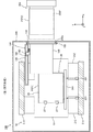
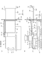
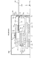
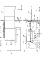
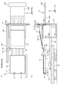
- FIG. 1A is a diagram schematically showing an exposure apparatus according to the first embodiment
- FIG. 1B is a sectional view taken along line AA of FIG. 1A. It is a cross-sectional view of FIG. 1A
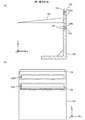
- FIG. 3A is a diagram showing the board loading / unloading unit of FIG. 1A taken out
- FIG. 3B is a state in which the board loading / unloading unit of FIG. 3A is viewed from the + X side.
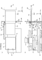
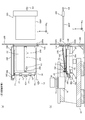
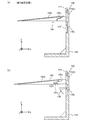
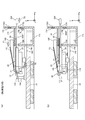
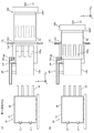
- FIG. 4 (a) and 4 (b) are a plan view of the vicinity of the stage device and a cross-sectional view taken along the line AA of FIG. 1 (a), and are views for explaining the substrate replacement operation of the first embodiment.
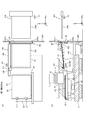
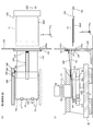
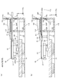
- 5 (a) and 5 (b) are a plan view of the vicinity of the stage device and a cross-sectional view taken along the line AA of FIG. 1 (a), and are views for explaining the substrate replacement operation of the first embodiment.
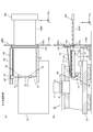
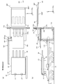
- the second). 6 (a) and 6 (b) are a plan view of the vicinity of the stage device and a sectional view taken along line AA of FIG. 1 (a), and are views for explaining the substrate replacement operation of the first embodiment.
- 7 (a) and 7 (b) are a plan view of the vicinity of the stage device and a cross-sectional view taken along the line AA of FIG. 1 (a), and are views for explaining the substrate replacement operation of the first embodiment. Part 4).
- 8 (a) and 8 (b) are a plan view of the vicinity of the stage device and a sectional view taken along line AA of FIG. 1 (a), and are views for explaining the substrate replacement operation of the first embodiment ( Part 5).
- 9 (a) and 9 (b) are a plan view of the vicinity of the stage device and a cross-sectional view taken along the line AA of FIG. 1 (a), and are views for explaining the substrate replacement operation of the first embodiment.
- 10 (a) and 10 (b) are a plan view of the vicinity of the stage device and a cross-sectional view taken along the line AA of FIG. 1 (a), and are views for explaining the substrate replacement operation of the first embodiment.
- 11 (a) and 11 (b) are a plan view of the vicinity of the stage device and a cross-sectional view taken along the line AA of FIG. 1 (a), and are views for explaining the substrate replacement operation of the first embodiment.
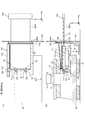
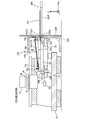
- the 8 It is a figure (the 1) which shows the exposure apparatus which concerns on 2nd Embodiment. It is a figure (the 2) which shows the exposure apparatus which concerns on 2nd Embodiment. It is a cross-sectional view of the exposure apparatus which concerns on 3rd Embodiment.
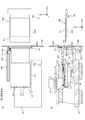
- 15 (a) and 15 (b) are a plan view and a vertical cross-sectional view of the vicinity of the stage device, and are views (No. 1) for explaining the substrate replacement operation of the third embodiment.
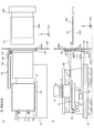
- 16 (a) and 16 (b) are a plan view and a vertical cross-sectional view of the vicinity of the stage device, and are views (No. 2) for explaining the substrate replacement operation of the third embodiment.
- 17 (a) and 17 (b) are a plan view and a vertical cross-sectional view of the vicinity of the stage device, and are views (No. 3) for explaining the substrate replacement operation of the third embodiment.
- 18 (a) and 18 (b) are a plan view and a vertical cross-sectional view of the vicinity of the stage device, and are views (4) for explaining the substrate replacement operation of the third embodiment.
- 19 (a) and 19 (b) are a plan view and a vertical cross-sectional view of the vicinity of the stage device of the exposure device according to the fourth embodiment, and are views (No.
- .. 20 (a) and 20 (b) are a plan view and a vertical cross-sectional view of the vicinity of the stage device of the exposure device according to the fourth embodiment, and are views (No. 2) for explaining the substrate replacement operation.
- .. 21 (a) and 21 (b) are diagrams for explaining the substrate loading / unloading unit according to the fifth embodiment.
- 22 (a) and 22 (b) are a cross-sectional view and a vertical cross-sectional view of the exposure apparatus according to the sixth embodiment, and are views (No. 1) for explaining a substrate replacement operation.
- 23 (a) and 23 (b) are a cross-sectional view and a vertical cross-sectional view of the exposure apparatus according to the sixth embodiment, and are views (No.
- FIG. 4 for explaining the substrate replacement operation of the eighth embodiment.
- 30 (a) and 30 (b) are diagrams (No. 5) for explaining the substrate replacement operation of the eighth embodiment.
- 31 (a) and 31 (b) are a cross-sectional view and a vertical cross-sectional view of the exposure apparatus according to the ninth embodiment, and are views (No. 1) for explaining a substrate replacement operation.
- 32 (a) and 32 (b) are diagrams (No. 2) for explaining the substrate replacement operation in the exposure apparatus according to the ninth embodiment.
- 33 (a) and 33 (b) are cross-sectional views of the exposure apparatus according to the tenth embodiment, and is a diagram (No. 1) for explaining a substrate replacement operation.
- 34 (a) and 34 (b) are cross-sectional views of the exposure apparatus according to the tenth embodiment, and is a diagram (No. 2) for explaining a substrate replacement operation.
- 35 (a) and 35 (b) are a cross-sectional view and a vertical cross-sectional view of the exposure apparatus according to the eleventh embodiment, and are views (No. 1) for explaining a substrate replacement operation.
- 36 (a) and 36 (b) are a cross-sectional view and a vertical cross-sectional view of the exposure apparatus according to the eleventh embodiment, and are views (No. 2) for explaining a substrate replacement operation.
- 37 (a) and 37 (b) are a cross-sectional view and a vertical cross-sectional view of the exposure apparatus according to the eleventh embodiment, and are views (No.
- FIG. 39 (a) is a vertical sectional view of the vicinity of the abutment member according to the twelfth embodiment
- FIG. 39 (b) is a sectional view taken along line BB of FIG. 39 (a).
- 40 (a) and 40 (b) are diagrams (No. 1) for explaining the substrate replacement operation in the twelfth embodiment.
- 41 (a) to 41 (c) are diagrams (No. 2) for explaining the substrate replacement operation in the twelfth embodiment. It is a figure for demonstrating the modification (the 1) of the substrate feeder.
- 43 (a) and 43 (b) are diagrams for explaining a modification (No. 2) of the substrate feeder.
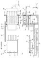
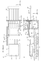
- FIG. 1A is a vertical cross-sectional view schematically showing the configuration of the exposure apparatus 100 according to the first embodiment. Further, FIG. 1 (b) shows a cross-sectional view taken along the line AA of FIG. 1 (a), and FIG. 2 shows a cross-sectional view of FIG. 1 (a). In FIG. 1B, the chamber 200 and the lighting system 12 are not shown for convenience.
- the exposure apparatus 100 includes a chamber 200, an exposure apparatus main body 10 housed in the chamber 200, a substrate loading / unloading unit 150, and a substrate slide hand 140.
- An external transfer robot 300 is provided outside the chamber 200 of the exposure apparatus 100, and the external transfer robot 300 transfers the substrate P from the external device (not shown) to the exposure device 100 and from the exposure device 100 to the external device. The substrate P is conveyed to.
- the chamber 200 forms a space in which the internal environment (at least one of temperature, humidity, pressure, and cleanliness) is adjusted, and an opening 200a used for loading and unloading the substrate P is formed in a part of the space. Has been done.
- the exposure apparatus main body 10 is of a step-and-scan method in which a rectangular (square) glass substrate P (hereinafter, simply referred to as a substrate P) used for a liquid crystal display device (flat panel display) or the like is used as an exposure object. It is a projection exposure device, a so-called scanner.
- the exposure apparatus main body 10 resists the illumination system 12, the mask stage 14 holding the mask M on which patterns such as circuit patterns are formed, the projection optical system 16, and the surface (the surface facing the + Z side in FIG. 1A). It has a stage device 20 for holding the substrate P coated with (sensitizer), a control system for these, and the like.
- the X-axis, Y-axis, and Z-axis orthogonal to each other with respect to the exposure apparatus main body 10 are set, and the mask M and the substrate P are attached to the projection optical system 16 at the time of exposure. It is assumed that the relative scanning is performed along the X-axis direction, and the Y-axis is set in the horizontal plane.
- rotation (tilt) directions around the X-axis, Y-axis, and Z-axis will be described as ⁇ x, ⁇ y, and ⁇ z directions, respectively.
- positions related to the X-axis, Y-axis, and Z-axis directions will be described as X-position, Y-position, and Z-position, respectively.
- the illumination system 12 is configured in the same manner as the illumination system disclosed in, for example, US Pat. No. 5,729,331, and irradiates the mask M with exposure illumination light (illumination light) IL.
- illumination light IL for example, light containing at least one wavelength of i-line (wavelength 365 nm), g-line (wavelength 436 nm), and h-line (wavelength 405 nm) is used.
- the wavelengths of the light source used in the illumination system 12 and the illumination light IL emitted from the light source are not particularly limited, and are ultraviolet rays such as ArF excimer laser light (wavelength 193 nm) and KrF excimer laser light (wavelength 248 nm). It may be light or vacuum ultraviolet light such as F 2 laser light (wavelength 157 nm).
- the mask stage 14 holds a light-transmitting mask M.
- the mask stage 14 is mounted on a pair of mask stage guides 218 fixed on the lens barrel surface plate 216 in a non-contact state.
- the pair of mask stage guides 218 are prismatic members whose longitudinal direction is the X-axis direction, and are arranged at predetermined intervals in the Y-axis direction as shown in FIG. 1 (b).
- the mask stage 14 is driven with a predetermined stroke in the scanning direction (X-axis direction) by, for example, a mask stage drive system (not shown) including a linear motor.
- the mask stage 14 is driven by a fine movement drive system that moves the X position and the Y position by a stroke in order to adjust the relative position with at least one of the lighting system 12, the stage device 20, and the projection optical system 16.
- the position information of the mask stage 14 is obtained by, for example, a mask stage position measurement system (not shown) including a linear encoder system and an interferometer system.
- the projection optical system 16 is supported by the lens barrel surface plate 216 below the mask stage 14 (-Z side).
- the projection optical system 16 is a so-called multi-lens type projection optical system having the same configuration as the projection optical system disclosed in, for example, US Pat. No. 6,552,775, and forms, for example, an erect image. It has multiple optical systems that are telecentric on both sides.
- the projection optical system 16 does not have to be a multi-lens type. It may be composed of one projection optical system as used in a semiconductor exposure apparatus.
- the exposure apparatus main body 10 when the mask M located in a predetermined illumination region is illuminated by the illumination light IL from the illumination system 12, a projected image (partial pattern image) of the mask M pattern in the illumination region is illuminated. ) Is formed in the exposed region by the projection optical system 16. Then, the mask M moves relative to the illumination region (illumination light IL) in the scanning direction, and the substrate P moves relative to the exposure region in the scanning direction, so that scanning exposure is performed on the substrate P. The pattern formed on the mask M (the entire pattern corresponding to the scanning range of the mask M) is transferred.
- the stage device 20 includes a surface plate 22, a board table 24, a support device 26, and a board holder 28.
- the surface plate 22 is provided on a pair of stage mounts 212 supported from below by a vibration isolator 210 installed on the floor F.
- the pair of stage mounts 212 support the pair of side columns 214, and the pair of side columns 214 support the lens barrel surface plate 216.
- the surface plate 22 is composed of, for example, a rectangular plate-shaped member in a plan view (viewed from the + Z side) arranged so that the upper surface (+ Z plane) is parallel to the XY plane.
- the support device 26 is placed on the surface plate 22 in a non-contact state, and supports the substrate table 24 from below in a non-contact state.
- the board holder 28 is arranged on the board table 24, and the board table 24 and the board holder 28 are integrally driven by a stage drive system (not shown) included in the stage device 20.
- the stage drive system includes, for example, a linear motor, and includes a coarse motion system capable of driving the substrate table 24 in the X-axis and Y-axis directions (along the upper surface of the platen 22) with a predetermined stroke, and a voice coil motor, for example.
- the substrate table 24 is provided with a fine movement system that microdrives the substrate table 24 in six degrees of freedom (X-axis, Y-axis, Z-axis, ⁇ x, ⁇ y, and ⁇ z) directions.
- the stage device 20 includes, for example, an optical interferometer system and an encoder system, and includes a stage measurement system for obtaining position information of the board table 24 in the six degrees of freedom direction.
- FIGS. 1B and 2 show a Y interferometer 32Y included in the stage measurement system and a Y moving mirror (bar mirror) 34Y having a reflecting surface orthogonal to the Y axis.
- the Y moving mirror 34Y is fixed to the substrate table 24.
- the substrate holder 28 has a rectangular upper surface 28u (+ Z side surface) in a plan view, and the substrate P is placed on the upper surface 28u. As shown in FIG. 2, the upper surface 28u of the substrate holder 28 has substantially the same aspect ratio as the substrate P. As an example, the lengths of the long side and the short side of the upper surface 28u are set to be slightly shorter than the lengths of the long side and the short side of the substrate P, respectively.
- the upper surface 28u of the board holder 28 is finished flat over the entire surface. Further, a plurality of minute holes (not shown) for blowing air and a plurality of minute holes (not shown) for vacuum suction are formed on the upper surface 28u of the substrate holder 28. A common hole may be used in combination as a minute hole for blowing air and a minute hole for vacuum suction.
- the substrate holder 28 sucks air between the upper surface 28u and the substrate P through the plurality of holes by using a vacuum suction force supplied from a vacuum device (not shown), and attaches the substrate P to the upper surface 28u. It is possible to adsorb (correct the plane).
- the substrate holder 28 is a so-called pin chuck type holder, in which a plurality of pins (pins having a diameter as small as, for example, about 1 mm in diameter) are arranged at substantially equal intervals.
- the substrate holder 28 can reduce the possibility of supporting the substrate P by sandwiching dust or foreign matter, and can reduce the possibility of deformation of the substrate P due to the sandwiching of the foreign matter.
- the substrate P is held (supported) on the upper surfaces of the plurality of pins.
- the XY plane formed by the upper surfaces of the plurality of pins is defined as the upper surface of the substrate holder 28.
- the substrate holder 28 supplies (supplys) the pressurized gas (for example, air) supplied from the pressurized gas supply device (not shown) between the upper surface 28u and the substrate P through the hole. Therefore, the back surface of the substrate P attracted to the substrate holder 28 can be separated from the upper surface 28u (the substrate P is floated). Further, in each of the plurality of holes formed in the substrate holder 28, there may be a time lag in the timing of supplying the pressurized gas, or the location of the hole for vacuum suction and the hole for supplying the pressurized gas. The ground contact state of the substrate P is controlled by appropriately exchanging the gas and changing the air pressure between suction and air supply (for example, an air pool between the back surface of the substrate P and the upper surface 28u of the substrate holder 28). Can be done).
- the pressurized gas for example, air supplied from the pressurized gas supply device (not shown) between the upper surface 28u and the substrate P through the hole. Therefore, the back surface of the substrate P attracted to the substrate
- the substrate holder 28 may perform plane correction of the substrate P in a state where the substrate P is not attracted to the upper surface 28u and is floated and supported.
- the substrate holder 28 supplies (supplys) the pressurized gas (for example, air) supplied from the pressurized gas supply device (not shown) to the back surface of the substrate P through the holes, thereby supplying (supplying) the substrate.
- a gas is interposed between the lower surface of P and the upper surface 28u of the substrate holder 28 (that is, a gas film is formed).
- the substrate holder 28 sucks the gas between the substrate holder 28 and the substrate P through the hole for vacuum suction by using a vacuum suction device, and a force (preload) downward in the direction of gravity with respect to the substrate P. ) Is applied to impart rigidity in the direction of gravity to the gas film. Then, the substrate holder 28 floats the substrate P in the Z-axis direction through a minute clearance and holds (supports) the substrate P in a non-contact manner by balancing the pressure and flow rate of the pressurized gas with the vacuum suction force.
- a force for controlling the flatness may be applied to P.
- Each hole may be formed by processing the substrate holder 28, or the substrate holder 28 may be formed of a porous material to supply or suck air.
- the upper surface 28u of the substrate holder 28 that floats and supports the substrate P is not a surface on which a hole is formed, but a virtual surface located above the surface by the above clearance, that is, a plane-corrected substrate.
- the upper surface is the upper surface 28u.
- the substrate carry-in bearer device 25 includes a suction pad 27 that sucks and holds the lower surface of the substrate P by a vacuum suction force supplied from a vacuum device (not shown), and a Z drive mechanism 23Z that drives the suction pad 27 along the Z-axis direction. And a Y drive mechanism 23Y that drives the Z drive mechanism 23Z (and the suction pad 27) along the Y-axis direction.
- the suction pad 27 is located in the most ⁇ Z side and is in the notch 28a formed in the substrate holder 28. Further, the suction pad 27 is located above the substrate holder 28 in a state where it is located on the + Z side most.
- the mask M is loaded onto the mask stage 14 by a mask loader (not shown) under the control of a main control device (not shown), and the substrate loading / unloading unit 150 and the substrate slide, which will be described later, are loaded.
- the hand 140 carries the board P onto the board holder 28.
- the main control device executes alignment measurement using an alignment detection system (not shown), and after the alignment measurement is completed, a plurality of shot regions set on the substrate P are sequentially exposed by a step-and-scan method. The operation is performed. Since this exposure operation is the same as the exposure operation of the step-and-scan method that has been conventionally performed, the X direction is set as the scan direction.
- the substrate P for which the exposure process has been completed is carried out from the substrate holder 28 by the substrate slide hand 140 or the like, and another substrate P to be exposed next is carried into the substrate holder 28, whereby the substrate P is carried onto the substrate holder 28.
- the substrate P is replaced, and a series of exposure operations for the plurality of substrates P are continuously performed.
- FIG. 1A shows a state in which the board loading / unloading unit 150 is taken out from FIG. 1A
- FIG. 3B shows the board loading / unloading unit 150 of FIG. 3A from the + X side. The state you saw is shown.
- the substrate loading / unloading unit 150 includes an XZ inverted L-shaped strut member 152, a carry-in inlet shutter 154 and a carry-out outlet shutter 156 provided on the striking member 152, and a striking member 152.
- the substrate feeder 160 fixed to the above is provided.
- the abutment member 152 has a rectangular shape when viewed from the X-axis direction, and has a carry-in inlet 152U and a carry-out outlet which are formed through the X-axis direction. It has 152L.
- the size of the carry-in inlet 152U and the carry-out outlet 152L is so small that the substrate P can pass through, and it is difficult for dust to enter the chamber 200 through the carry-in inlet 152U and the carry-out outlet 152L.
- a carry-in inlet shutter 154 that opens and closes the carry-in entrance 152U by sliding in the vertical direction (Z-axis direction) is provided.
- a carry-out outlet shutter 156 that opens and closes the carry-out outlet 152L by rotating around a rotation shaft 156a extending in the Y-axis direction is provided.
- the substrate feeder 160 is cantilevered by the countersunk member 152 at a predetermined height from the floor F.
- the "position at a predetermined height” is a height position at which the stage device 20 can be positioned below the board feeder 160 when the stage device 20 moves to the board replacement position (see FIG. 8B).
- the substrate feeder 160 includes a plate-like member having a substantially right-angled triangular XZ cross section, and the upper surface of the substrate feeder 160 is inclined with respect to the XY plane. In the example of FIG. 3A, the + X side end of the upper surface of the substrate feeder 160 is parallel to the XY plane.
- a plurality of minute holes (not shown) for blowing air are formed on the upper surface of the substrate feeder 160.
- pressurized gas for example, air
- a pressurized gas supply device (not shown) is supplied (air supply) to the back surface of the substrate P placed on the upper surface of the substrate feeder 160 via a hole. )
- the substrate feeder 160 has a hole for sucking and holding the lower surface of the substrate P by a vacuum suction force supplied from a vacuum device (not shown).
- the hole for supplying the pressurized gas and the hole for vacuum suction may be a common hole.
- the substrate feeder 160 is provided above the corners on the + X side and + Y side of the surface plate 22. Further, as shown in FIG.
- the end portion of the substrate feeder 160 on the ⁇ X side extends below the lens barrel surface plate 216, and the substrate feeder 160 is partly formed on the lens barrel surface plate 216.
- a notch 216a is formed to avoid contact with the substrate P held by the surface.
- the substrate slide hand 140 is provided on the + Y side of the substrate feeder 160.
- the substrate slide hand 140 has a suction pad 142 and a vertical movement mechanism 144 that moves the suction pad 142 up and down (reciprocally drives along the Z-axis direction).
- the vertical movement mechanism 144 is movable in the X-axis direction along the rail 146 laid at a predetermined height from the floor F along the X-axis direction. That is, the suction pad 142 is movable in the X-axis direction and the Z-axis direction.
- the suction pad 142 can suck and hold the lower surface of the substrate P by a vacuum suction force supplied from a vacuum device (not shown).
- the substrate slide hand 140 pulls the substrate P from the outside to the inside of the chamber 200 by sucking and holding a part of the lower surface of the substrate P conveyed by the external transfer robot 300 and moving it in the ⁇ X direction. Further, the substrate slide hand 140 moves along the upper surface of the substrate feeder 160 while holding the substrate P drawn into the chamber 200, thereby delivering the substrate P onto the substrate feeder 160. Further, the substrate slide hand 140 attracts and holds a part of the lower surface of the exposed substrate P placed on the substrate holder 28 and moves in the + X direction to move the substrate P from the inside of the chamber 200 to the outside. Send out.
- the external transfer robot 300 transfers the substrate P between the exposure device 100 and an external device (not shown) such as a coater / developer provided outside the exposure device 100 (chamber 200). As shown in FIGS. 1A and 2, the external transfer robot 300 has a flat plate-shaped robot hand 300F. Although not shown, a plurality of minute holes (not shown) for blowing air are formed on the upper surface of the robot hand 300F. In the robot hand 300F, pressurized gas (for example, air) supplied from a pressurized gas supply device (not shown) is supplied (air supply) to the back surface of the substrate P placed on the upper surface of the robot hand 300F via a hole.
- pressurized gas for example, air supplied from a pressurized gas supply device (not shown) is supplied (air supply) to the back surface of the substrate P placed on the upper surface of the robot hand 300F via a hole.
- the back surface of the substrate P can be separated from the upper surface of the robot hand 300F (the substrate P is levitated). Further, the robot hand 300F has a hole for sucking and holding the lower surface of the substrate P by a vacuum suction force by a vacuum device (not shown).
- the hole for supplying the pressurized gas and the hole for vacuum suction may be a common hole.
- FIGS. 4 (a) and 4 (b) show a plan view of the vicinity of the stage device 20 at the same timing and a cross-sectional view taken along the line AA of FIG. 1 (a). 5 (b), 6 (a) and 6 (b), ... FIGS. 11 (a) and 11 (b) also show a plan view and a sectional view taken along line AA in the vicinity of the stage device at the same timing. Shown. Note that, in FIGS. 4A to 11B, the configuration of the exposure apparatus 100, which is not necessary for explanation, is omitted.
- the board P1 is placed in advance on the board holder 28 of the stage device 20. Further, in the substrate replacement operation, an operation of carrying out the exposed substrate P1 and an operation of loading (mounting) the newly exposed substrate P2 (separate from the substrate P1) into the substrate holder 28 are executed. It shall be.
- the substrate P2 may be an unexposed (not exposed even once) substrate, or may be a substrate to be exposed for the second and subsequent times.
- the main control device moves an external transfer robot 300 that holds the substrate P2 before exposure in the vicinity of the chamber 200. Drive to (near the carry-in entrance 152U).
- the robot hand 300F of the external transfer robot 300 is in contact with most of the lower surface ( ⁇ Z surface) of the substrate P2, but is not in contact with the lower surface of the ⁇ X side end of the substrate P2. It shall be.
- the main control device opens the carry-in inlet 152U by sliding the carry-in inlet shutter 154 in the + Z direction (see arrow A1 in FIG. 4B).
- the main control device drives the external transfer robot 300 in the ⁇ X direction (see arrow A2 in FIGS. 4A and 4B), and puts the end of the substrate P2 on the ⁇ X side into the chamber 200. Let it enter.
- the end portion of the substrate P2 on the ⁇ X side is located above the substrate feeder 160.
- the external transfer robot 300 does not enter the chamber 200. As a result, the ingress of dust into the chamber 200 can be suppressed as much as possible.
- the main control device drives the substrate slide hand 140 to move the suction pad 142 in the + X direction (arrow A3 direction in FIG. 4B) and the + Z direction (arrow A4 direction), thereby causing the suction pad 142. Is in contact with a part of the lower surface of the substrate P2 (the end on the ⁇ X side and the + Y side). Further, the main control device starts suction holding of a part of the lower surface ( ⁇ Z surface) of the substrate P2 by the suction pad 142 (see the black arrow A5 in FIG. 4 (b)).
- the main control device starts supplying (supplied) the pressurized gas from the upper surface of the robot hand 300F of the external transfer robot 300 and the upper surface of the substrate feeder 160 (see arrows B1 and B2 in FIG. 5B). ..
- the substrate P2 rises from the upper surface of the robot hand 300F and the upper surface of the substrate feeder 160, and the friction between the lower surface of the substrate P2 and the upper surface of the robot hand 300F and the upper surface of the substrate feeder 160 is negligible (low friction state). )become.
- the main control device drives the suction pad 142 of the substrate slide hand 140 in the ⁇ X direction (arrow B2 direction in FIG.
- the suction pad 142 is moved in the direction along the upper surface of the substrate feeder 160 (directions shown by arrows B5 in FIGS. 5A and 5B, and directions inclined in the XZ plane in the X-axis and the Z-axis).
- the substrate P2 is conveyed into the chamber 200 along the upper surface of the robot hand 300F and the upper surface of the substrate feeder 160.
- the substrate P2 is moved by the substrate slide hand 140 while being supported by the upper surface of the robot hand 300F and the upper surface of the substrate feeder 160.
- FIGS. 6 (a) and 6 (b) are illustrations of FIGS. 6 (a) and 6 (b)
- the main control device is brought into the carry-in inlet.
- the shutter 154 is slid in the ⁇ Z direction to close the carry-in inlet 152U (see arrow C1 in FIG. 6B).
- the main control device drives the external transfer robot 300 in the ⁇ X direction (see arrows C2 in FIGS. 6 (a) and 6 (b)).
- exposure apparatus main body 10 exposure to the substrate P1 is continuously performed.
- the main control device drives a vacuum device (not shown) of the board feeder 160, and sucks and holds the board P2 by a vacuum suction force. Then, the main control device releases the suction holding by the suction pad 142 of the substrate slide hand 140, and drives the suction pad 142 downward in the ⁇ Z direction (see arrow D1 in FIG. 7B). Further, the main control device drives the external transfer robot 300 in the ⁇ Z direction (see arrow D2) and also in the ⁇ X direction (see arrow D3) to bring out the ⁇ X end of the robot hand 300F. Bring it closer to 152L.
- the main control device opens the carry-out outlet 152L by rotationally driving the carry-out outlet shutter 156 in the counterclockwise direction (arrow D4 direction). As a result, the preparation for replacement of the board on the board holder 28 is completed. At this stage, it is assumed that the exposure operation for the substrate P1 on the substrate holder 28 is completed.
- the main control device drives the stage device 20 to the substrate replacement position (below the substrate feeder 160) (see arrows E1 in FIGS. 8A and 8B).
- the main control device slightly raises the suction pad 27 of the substrate carry-in bearer device 25 (see arrow E2), and causes the suction pad 27 to suck and hold the lower surface of the substrate P1 (see arrow E3).
- the main control device slightly raises the substrate P1 with respect to the upper surface 28u of the substrate holder 28 by starting the supply (air supply) of the pressurized gas from the upper surface 28u of the substrate holder 28 (see arrow E4). ..
- the main control device slightly offsets the substrate P1 from the substrate holder 28 in the + Y direction by moving the suction pad 27 that sucks and holds the substrate P1 in the + Y direction (see arrow E5). Due to this offset, the suction pad 142 of the substrate slide hand 140 can hold the corners on the ⁇ X side and the + Y side of the lower surface of the substrate P1.
- the main control device drives the suction pad 142 of the board slide hand 140 ascending (see arrow E6) with the board P1 offset from the board holder 28, and causes the suction pad 142 to suck and hold the lower surface of the board P1. It is assumed that the main control device has started supplying (supplied) the pressurized gas from the upper surface of the robot hand 300F of the external transfer robot 300 at the stages of FIGS. 8 (a) and 8 (b). (See arrow E7). At the stage of FIG. 7B, the main control device opened the carry-out outlet 152L by rotationally driving the carry-out outlet shutter 156 in the counterclockwise direction (arrow D4 direction), but FIG. 8 (b) ), The carry-out port 152L may be opened.
- the main control device drives the suction pad 142 of the substrate slide hand 140 in the + X direction (see the arrows F1 in FIGS. 9A and 9B), and moves the substrate P1 from above the substrate holder 28 to the robot hand 300F. Slide it up. As a result, the exposed substrate P1 is delivered onto the robot hand 300F. That is, the substrate P1 is moved by the substrate slide hand 140 while being supported by the upper surface of the substrate holder 28 and the upper surface of the robot hand 300F.
- the main control device stops the supply (intake) of the pressurized gas from the robot hand 300F at the timing when the robot hand 300F receives the substrate P1, drives a vacuum device (not shown), and uses a vacuum suction force to drive the robot.
- the substrate P1 is attracted and held by the hand 300F.
- the main control device drives the suction pad 27 of the substrate carry-in bearer device 25 ascending (see arrow F2) and brings it into contact with the ⁇ X end of the lower surface of the substrate P2 held by the substrate feeder 160 to bring the suction pad 27 into contact. Starts adsorption and holding of the substrate P2 by (see arrow F3).
- the main control device drives the stage device 20 in the ⁇ X direction in a state where the suction pad 27 of the substrate carry-in bearer device 25 sucks and holds the substrate P2 (see arrow G1).
- the stage device 20 moves away from the substrate feeder 160, the area of the substrate P2 held by the substrate feeder 160 gradually decreases, and the area of the substrate P2 supported by the substrate holder 28 gradually increases. ..
- the substrate P2 is delivered from the substrate feeder 160 onto the substrate holder 28.
- the main control device lowers and drives the suction pad 142 after the substrate P1 is delivered to the robot hand 300F (see arrow G2), and rotates the carry-out outlet shutter 156 in the clockwise direction (see arrow G3). , Close the carry-out port 152L. As a result, it is possible to prevent dust from entering from the outside to the inside of the chamber 200 through the carry-out port 152L.
- the main control device drives the external transfer robot 300 holding the substrate P1 in the + X direction (see arrow G4) to convey the substrate P1 to the external device.
- the main control device stops the supply (air supply) of the pressurized gas from the upper surface of the substrate feeder 160. Further, the main control device finely drives the suction pad 27 to align (position adjust) the substrate P2 (see arrow H1). After that, the main control device drives the suction pad 27 downward (see arrow H2), starts suction holding of the substrate P2 by the substrate holder 28, and exposes the substrate P2 newly placed on the substrate holder 28. Start.
- the exposure apparatus 100 is conveyed by the exposure apparatus main body 10, the chamber 200 accommodating the exposure apparatus main body 10, and the external transfer robot 300 outside the chamber 200.
- the substrate feeder 160 that receives and holds the incoming substrate P, the substrate P is delivered from the external transfer robot 300 to the substrate feeder 160, and the substrate P is delivered from the substrate feeder 160 onto the substrate holder 28 of the exposure apparatus main body 10.
- It includes a board slide hand 140 and a board carry-in bearer device 25 for transferring the board P from above the board holder 28 to the external transfer robot 300. This eliminates the need for the substrate transfer port portion previously provided (for example, Japanese Patent Application Laid-Open No.
- the substrate transfer port portion is provided at a position between the exposure apparatus main body 10 and the external transfer robot 300, in the exposure apparatus 100 without the substrate transfer port portion, the size of the apparatus is reduced by the amount of the substrate transfer port portion. (Footprint can be narrowed). Further, the cost of the exposure apparatus 100 can be reduced by omitting the substrate transfer port portion. Further, in the exposure apparatus having the substrate transfer port portion, the substrate P undergoes the substrate transfer operation twice from the external transfer robot 300 to the substrate transfer port portion and from the substrate transfer port portion to the substrate holder 28. Extra stress is applied to the substrate P each time the substrate is delivered, and the substrate P may be deformed or damaged. Therefore, when the substrate transfer operation occurs only once between the exposure apparatus main body 10 and the external transfer robot 300 as in the first embodiment, there is an effect that the substrate P is less likely to be deformed or damaged.
- the substrate slide hand 140 holds a part of the substrate P, and when the substrate P is transferred from the substrate feeder 160 to the substrate holder 28, the substrate feeder 160 and the substrate holder 28 are transferred. It moves in the direction including the X-axis direction in which and are lined up. As a result, the substrate P can be transferred from the substrate feeder 160 onto the substrate holder 28 as the substrate slide hand 140 moves.
- the upper surface (board support surface) of the board feeder 160 is inclined with respect to the upper surface of the board holder 28, and the board carry-in bearer device 25 holds a part of the board P.
- the substrate P is transferred from the substrate feeder 160 to the substrate holder 28.
- the substrate P can be delivered to the substrate holder 28 while sliding the substrate P along the upper surface of the substrate feeder 160, so that bending of the substrate P when the substrate P is delivered to the substrate holder 28 is suppressed. can do.
- the external transfer robot 300 since the external transfer robot 300 does not enter the chamber 200 of the exposure apparatus 100, it is possible to prevent dust adhering to the external transfer robot 300 from entering the chamber 200. Further, since the volume of the chamber 200 can be reduced, the temperature inside the chamber 200 can be easily controlled. Further, since the external transfer robot 300 does not enter the chamber 200, contact between the external transfer robot 300 and each part of the exposure apparatus 100 can be suppressed as much as possible. Further, the openings connecting the inside of the chamber 200 and the outside of the chamber 200 are only the carry-in inlet 152U and the carry-out outlet 152L having a size sufficient to move the substrate P, and it is possible to prevent dust from entering the chamber.
- the + X side end portion of the upper surface of the substrate feeder 160 is parallel to the XY plane.
- the substrate slide hand 140 can easily receive the substrate P conveyed by the external transfer robot 300.
- the substrate P on the substrate holder 28 is delivered to the external transfer robot 300 in a state where the substrate P is held on the upper surface of the substrate feeder 160, and immediately after that, the substrate held by the substrate feeder 160 is held. P is to be delivered onto the substrate holder 28.
- the board on the board holder 28 can be quickly replaced even if there is no board transfer port portion.
- the carry-in inlet 152U and the carry-out port 152L of the abutment member 152 are separately provided, the carry-in inlet 152U and the carry-out port 152L are not opened at the same time during the board exchange operation, and the carry-in entrance 152L is not opened at the same time.
- the suction pad 27 of the substrate carry-in bearer device 25 is movable in the Y-axis direction, but the present invention is not limited to this.
- the suction pad 142 of the board slide hand 140 can suck and hold the lower surface of the board P without moving the board P on the board holder 28 in the Y-axis direction (without offsetting), the suction pad 27 may not be able to move in the Y-axis direction.
- the robot hand 300F of the external transfer robot 300 is a flat plate-shaped member capable of air-floating the substrate P on the upper surface
- the present invention is not limited to this.
- the robot hand 300F may be a fork-shaped member or the like as long as the substrate P can be slid without generating dust.
- the robot hand 300F may have a rotating roller that feeds the substrate P in the X-axis direction by rolling contact. By providing the rotating roller on the robot hand 300F, it is possible to reduce friction when the substrate P comes into contact with the robot hand 300F and suppress dust generation.
- a mechanism is provided in the vicinity of the carry-in inlet 152U and the carry-out port 152L of the board carry-in / out unit 150 to apply a levitation force to the board P by supplying (supplying) pressurized gas. You may. Further, a rotating roller that feeds the substrate P in the X-axis direction by rolling contact may be provided in the vicinity of the carry-in inlet 152U and the carry-out outlet 152L of the board carry-in / out unit 150.
- the present invention is not limited to this.
- the substrate feeder 160 may be fixed to a member different from the abutment member 152.
- the substrate feeder 160 is provided above the corners on the + X side and + Y side of the surface plate 22 , but the present invention is not limited to this.
- the substrate feeder 160 may be provided, for example, above the + X side end portion and the Y-axis direction center portion of the surface plate 22 as long as it does not interfere with the exposure operation.
- the carry-in inlet shutter 154 and the carry-out outlet shutter 156 are provided on the abutment member 152 of the substrate carry-in / out unit 150 , but the present invention is not limited to this. That is, at least one of the carry-in inlet shutter 154 and the carry-out outlet shutter 156 may be provided in the chamber 200.
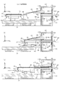
- FIG. 12 is a diagram showing the exposure apparatus 100A according to the second embodiment (a diagram corresponding to FIG. 1A of the first embodiment).
- the board feeder 160 is fixed to the abutment member 152 of the board loading / unloading unit 150, but in the board loading / unloading unit 150A of the second embodiment, as shown in FIG. 12, the striking member The substrate feeder 161 is attached to the rotating shaft 162 provided on the 152.
- the shape and function of the substrate feeder 161 are the same as those of the substrate feeder 160 of the first embodiment, but since the substrate feeder 161 is attached to the rotating shaft 162 extending in the Y-axis direction, the rotating shaft 162 is the center. It can rotate freely. Although not shown in FIGS. 12 and 13, the substrate feeder 161 is rotated by a drive mechanism (including a motor and the like) (not shown).
- the notch 216b formed in the lens barrel surface plate 216 mechanically interferes with the substrate feeder 161 and the substrate slide hand 140. It is set larger than the notch 216a of the first embodiment in order to avoid the above.
- the substrate feeder 161 has a state in which the upper surface (board support surface) is parallel to the XY surface as shown in FIG. 12 and a state in which the substrate support surface is inclined with respect to the XY surface as shown in FIG. 13 (first embodiment). Transition to and from a state similar to the morphology).
- the main control device controls the drive mechanism when the substrate P (P2) is carried in from the outside of the chamber 200 by the substrate slide hand 140, and as shown in FIG. 12, the substrate support surface. Keep (upper surface) parallel to the XY plane. Further, when the substrate slide hand 140 pulls the substrate P (P2) onto the substrate feeder 161, the main control device supplies pressurized gas from the upper surface of the external transfer robot 300 and the substrate support surface of the substrate feeder 161 (air supply). ). As a result, the substrate support surface (upper surface) of the substrate feeder 161 and the support surface of the external transfer robot can be flush with each other (in the same plane). In this state, since the main control device moves the substrate P2 by the substrate slide hand 140, it is possible to prevent the substrate P2 from being deformed or damaged due to excessive stress.
- the main control device starts suction holding of the substrate P (P2) by the substrate feeder 161. Further, the main control device controls the drive mechanism to rotate the substrate feeder 161 counterclockwise as shown in FIG. 13, and after inclining the substrate support surface of the substrate feeder 161 with respect to the XY surface, As in the first embodiment, the substrate on the substrate holder 28 is replaced.
- the substrate feeder 161 is capable of transitioning between a state in which the substrate support surface is parallel to the XY surface and a state in which the substrate support surface is inclined.
- the substrate feeder 161 When receiving P from the external transfer robot 300 or delivering it to the substrate holder 28, it is possible to set an appropriate state (posture). As a result, the possibility of contact between the carry-in inlet 152U or the substrate feeder 161 and the substrate P can be reduced.
- the substrate slide hand 140 carries the substrate P (P2) from the external transfer robot 300 into the chamber 200, it is not necessary to change the height position (position in the Z-axis direction) of the suction pad 142.
- the control of the suction pad 142 can be simplified.
- the substrate support surface of the substrate feeder 161 is tilted, and the ⁇ X end of the substrate P (P2) newly placed on the substrate holder 28 is the substrate holder. Since it can be brought close to the upper surface of the board 28, the stroke of the suction pad 142 of the board carry-in bearer device 25 in the Z direction can be shortened (or set to 0), and the board P (P2) to the board holder 28 can be shortened (or set to 0). Delivery can be performed smoothly without impact.
- the rotating shaft 162 is located at the + X end of the substrate feeder 161
- the present invention is not limited to this, and for example, the rotating shaft 162 is located at the intermediate portion in the X-axis direction of the substrate feeder 161. It may be located.
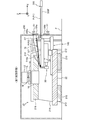
- FIG. 14 shows a cross-sectional view of the exposure apparatus 100B according to the third embodiment (a diagram corresponding to FIG. 2 of the first embodiment).
- the exposure apparatus 100 of the first embodiment described above includes the substrate slide hand 140, but the exposure apparatus 100B of the third embodiment has the first slide hand 240 and the second slide hand 240 instead of the substrate slide hand 140. It is equipped with a slide hand 340.
- the first slide hand 240 is provided on the upper surface (board support surface) of the board feeder 163.
- the substrate feeder 163 has the same configuration and function as the substrate feeder 160 of the first embodiment.
- the first slide hand 240 has a rail 246 provided on the substrate support surface of the substrate feeder 163 and a suction pad 242 that moves along the rail 246.
- the rail 246 is embedded in the substrate feeder 163, and it is assumed that there is no step between the upper surface of the rail 246 and the upper surface (board support surface) of the substrate feeder 163.
- the first slide hand 240 draws the substrate P into the chamber 200 (on the substrate feeder 163) by sucking and holding a part of the substrate P conveyed by the external transfer robot 300 and moving it in the ⁇ X direction. be able to.
- the second slide hand 340 is provided on the + X side surface of the stage device 20 (board table 24).
- the second slide hand 340 has the same configuration as the substrate slide hand 140 of the first embodiment, and includes a rail 346 extending in the X-axis direction, a Z drive mechanism 344 moving in the X-axis direction along the rail 346, and the like. It has a suction pad 342 driven in the Z-axis direction by the Z drive mechanism 344.
- the second slide hand 340 sucks and holds a part of the substrate P placed on the substrate holder 28 and moves it in the + X direction to deliver the substrate P from the substrate holder 28 to the external transfer robot 300. Can be done.
- the same functions as the substrate slide hand 140 of the first embodiment are realized by the first slide hand 240 and the second slide hand 340.
- FIGS. 14 to 18 (b) show a plan view and a vertical cross-sectional view of the vicinity of the stage device 20 at the same timing
- a) and FIGS. 17 (b), 18 (a) and 18 (b) also show a plan view and a vertical cross-sectional view of the vicinity of the stage device at the same timing. Note that, in FIGS. 15 (a) to 18 (b), among the configurations of the exposure apparatus 100B, illustration of configurations unnecessary for explanation is omitted.
- the main control device sets an external transfer robot 300 that holds the substrate P2 before exposure in the vicinity of the chamber 200 in a state where the substrate P1 on the substrate holder 28 is exposed in the exposure apparatus main body 10. Drive to (near the carry-in entrance 152U). At this stage, it is assumed that the suction pad 242 of the first slide hand 240 is located at the + X end of the rail 246.
- the main control device opens the carry-in inlet 152U by sliding the carry-in inlet shutter 154 in the + Z direction (see arrow J1 in FIG. 15B).
- the main control device drives the external transfer robot 300 in the ⁇ X direction (see arrow J2 in FIGS. 15 (a) and 15 (b)), and the end portion of the substrate P2 on the ⁇ X side is placed in the chamber 200. Let it enter.
- the end portion of the lower surface of the substrate P2 on the ⁇ X side is in close proximity to or in contact with the suction pad 242.
- the main control device starts suction holding of a part of the lower surface of the substrate P2 by the suction pad 242 (see arrow J3 in FIG. 15B).
- the main control device starts supplying (air supply) the pressurized gas from the upper surface of the robot hand 300F of the external transfer robot 300 and the upper surface of the substrate feeder 163, and the suction pad 242 of the first slide hand 240 is rail 246. It is driven toward the ⁇ X side (direction of arrow K1 in FIGS. 16 (a) and 16 (b)) along the above. As a result, the substrate P2 is conveyed into the chamber 200 along the upper surface of the robot hand 300F and the upper surface of the substrate feeder 163.
- the main control device stops the supply of the pressurized gas from the substrate feeder 163 and the robot hand 300F, and starts the adsorption and holding of the substrate P2 by the substrate feeder 163. .. Then, the main control device closes the carry-in inlet shutter 154 and opens the carry-out outlet shutter 156.
- the main control apparatus drives the stage apparatus 20 to the positions shown in FIGS. 16A and 16B (board replacement positions) (see arrow K2). ..
- the main control device When the stage device 20 moves to the vicinity of the board replacement position, the main control device starts supplying the pressurized gas from the upper surface 28u of the board holder 28, and pushes the suction pad 27 of the board carry-in bearer device 25 in the + Z direction and the + Y direction. It is driven to offset the substrate P1 from the substrate holder 28 to the + Y side (see arrow K3 in FIG. 16A). Further, the main control device drives the external transfer robot 300 in the + X direction (see arrow K4).
- the main control device drives the external transfer robot 300 in the ⁇ Z direction and the ⁇ X direction (see arrows L1 and L2 in FIG. 17B) to bring the ⁇ X end of the robot hand 300F closer to the carry-out port 152L. .. Then, the main control device starts supplying (supplied) the pressurized gas from the upper surface of the robot hand 300F.
- the main control device ascends and drives the suction pad 342 of the second slide hand 340 to cause the suction pad 342 to suck and hold the lower surface of the substrate P1. Then, the main control device drives the suction pad 342 along the rail 346 in the + X direction (see arrow L3), and slides and conveys the substrate P1 from the substrate holder 28 onto the robot hand 300F. After the substrate P1 is slid and conveyed to the robot hand 300F, the main control device drives the robot hand 300F in the + X direction, retracts the substrate P1 to the outside of the chamber 200, and closes the carry-out outlet shutter 156.
- the main control device ascends and drives the suction pad 27 of the substrate carry-in bearer device 25 (see arrow L4), and starts suction holding of the ⁇ X end of the substrate P2 by the suction pad 27 (see arrow L5). Further, the main control device starts supplying the pressurized gas from the upper surface of the substrate feeder 163.
- the main control device drives the stage device 20 in the ⁇ X direction in a state where the suction pad 27 of the board carry-in bearer device 25 sucks and holds the board P2 (see arrow N1).
- the substrate P2 is delivered from the substrate feeder 163 to the substrate holder 28.
- the pressurized gas is supplied from the upper surface of the substrate holder 28.
- the main control device stops the supply of the pressurized gas from the upper surface of the substrate feeder 163. Further, the main control device finely drives the suction pad 27 to align the substrate P2 (position adjustment). After that, the main control device drives the suction pad 27 downward (see arrow N2), and starts exposure to the substrate P2 newly placed on the substrate holder 28.
- the main control device drives the external transfer robot 300 in the + X direction (see arrow N3) to transfer the substrate P1 to the external device.
- the first slide hand 240 is provided at the center of the substrate feeder 163 in the Y-axis direction, spaces are created on the + Y side and the ⁇ Y side of the substrate feeder 163. .. This makes it possible to make design changes such as holding the substrate feeder 163 from the Y-axis direction.
- the board unloading operation can be started before the stage device 20 arrives at the board replacement position.
- the suction pad 242 is driven as in the first embodiment.
- the control can be simplified as compared with the case where the control is performed in the two-axis directions of the X-axis and the Z-axis. Further, it is not necessary to provide the rail 146 as in the first and second embodiments, and the number of parts can be reduced.
- the board unloading operation can be started before the stage device 20 arrives at the board replacement position.
- the posture of the substrate feeder 163 (inclination of the substrate support surface) may be changed as in the second embodiment.
- the exposure apparatus 100C of the fourth embodiment will be described with reference to FIGS. 19 and 20.
- the exposure apparatus 100C of the fourth embodiment has substantially the same configuration as the exposure apparatus 100 of the first embodiment, but the substrate feeder 160 has a lower surface. The difference is that the substrate P has a function of non-contact suspension holding.
- a hole for exhausting pressurized gas is formed on the lower surface of the substrate feeder 160, and by exhausting air in the manner of a known Bernoulli chuck, the upper surface of the substrate P and the lower surface of the substrate feeder 160 It is possible to generate a negative pressure between the two. Therefore, in the fourth embodiment, the substrate P is held in a non-contact suspension by the negative pressure generated between the upper surface of the substrate P and the lower surface of the substrate feeder 160 (that is, the upper surface of the substrate P is the lower surface of the substrate feeder 160). Can be held in a non-contact manner).
- the present invention is not limited to this, and a hole for vacuum suction and a hole for exhausting pressurized gas are provided on the lower surface of the substrate feeder 160, and the substrate P is provided by balancing vacuum suction and air exhaust using these holes. It may be held in a non-contact suspension.
- FIGS. 19 (a) and 19 (b) show figures corresponding to FIGS. 8 (a) and 8 (b) of the first embodiment.
- the substrate P2 before exposure is held on the upper surface of the substrate feeder 160, and the stage device 20 and the exposed substrate P1 are placed at positions facing the lower surface of the substrate feeder 160. It is in a positioned state.
- the substrate P1 is slightly offset from the substrate holder 28 in the + Y direction, and the pressurized gas is supplied from the upper surface 28u of the substrate holder 28, so that the lower surface of the substrate P1 and the substrate holder 28 There is no contact with the upper surface.
- the suction pad 142 of the substrate slide hand 140 is in a state of sucking and holding a part of the lower surface of the substrate P1.
- the main controller exhausts the pressurized gas from the lower surface of the substrate feeder 160 to suspend and hold the substrate P1 on the lower surface of the substrate feeder 160 according to the Bernoulli chuck principle.
- the main control device sucks and holds a part of the substrate P2 on the substrate feeder 160 on the adsorption pad 27 of the substrate carry-in bearer device 25, and starts supplying the pressurized gas from the upper surface of the substrate feeder 160.
- the main control device moves the suction pad 142 of the substrate slide hand 140 in the + X direction (see arrow Q1) to externally convey the substrate P1.
- the substrate P2 is delivered from the substrate feeder 160 to the substrate holder 28.
- a negative pressure is generated on the lower surface of the substrate feeder 160 to suspend and hold the substrate P1 in a non-contact manner. Therefore, as shown in FIG. In this case, even if the substrate holder 28 does not exist under the substrate P1, the substrate P1 can be smoothly slid and transported to the external transfer robot 300.
- the substrate P1 is received from the substrate holder 28 onto the external transfer robot 300 in order to hold the substrate P1 to be carried out to the outside in a non-contact suspension on the lower surface of the substrate feeder 160.
- the stage device 20 does not have to wait at the board replacement position until it is handed over.
- the operation of placing the new substrate P2 on the substrate holder 28 can be started before the substrate P1 is delivered to the external transfer robot 300. Therefore, according to the fourth embodiment, it is possible to shorten the time required for substrate replacement.
- the substrate P1 held non-contactly on the lower surface of the substrate feeder 160 is delivered onto the external transfer robot 300. It may be.
- the carry-out port shutter 156 can be closed, and even if dust enters the chamber 200 from the carry-out port 152L, the stage device 20 can be kept closed. There is little risk of dust adhering to 20.
- the substrate feeder 160 of the fourth embodiment may be rotatably provided on the abutment member 152 as in the second embodiment. That is, the upper surface of the substrate feeder 160 may be transitioned between a state horizontal to the XY plane and a state inclined.
- the first slide hand 240 and the second slide hand 340 may be provided instead of the substrate slide hand 140.
- FIG. 21A shows the substrate loading / unloading unit 150 ′ according to the fifth embodiment.
- the board loading / unloading unit 150' has a board feeder 165 instead of the board feeder 160 of the board loading / unloading unit 150 of the first embodiment, and has a loading / unloading shutter 156'instead of the loading / unloading shutter 156. are doing.
- the substrate feeder 165 has a first portion 165a fixed to the ⁇ X side surface of the abutment member 152 and a second portion 165b that can be slidably moved with respect to the first portion 165a. It is assumed that the slide moving direction of the second portion 165b is the same as the inclination direction of the upper surface (board support surface) of the second portion 165b (the direction in which the X-axis and the Z-axis are inclined in the XZ plane). As shown in FIG. 21B, for example, a lead screw type drive mechanism 165c is provided between the first portion 165a and the second portion 165b.
- the drive mechanism 165c drives the second portion 165b so as to change the distance between the second portion 165b and the first portion 165a.
- the drive mechanism 165c is not limited to the feed screw type, and may be a drive mechanism of another type such as a drive mechanism including a linear motor.
- the substrate feeder 165 by adopting the above-described configuration as the substrate feeder 165, the first portion 165a and the second portion 165b are brought close to each other as shown in FIG. 21A except when the substrate is replaced. ..
- the substrate feeder 165 can be prevented from interfering with operations such as exposure operation and maintenance.
- the board replacement position can be set to a position closer to ⁇ X by moving the second portion 165b of the board feeder 165 as shown in FIG. 21 (b).
- the stroke in the X-axis direction when the stage device 20 moves to the substrate replacement position can be shortened.
- the board replacement position is set to the ⁇ X side of the first embodiment and the like, so that the board is replaced when the board is replaced.
- the distance between the holder 28 and the external transfer robot 300 may become long.
- the length of the carry-out outlet shutter 156'in the X-axis direction when the carry-out outlet 152L is opened is shown in FIG. 1 (b) and the like. It is set longer than the carry-out outlet shutter 156, and the carry-out outlet shutter 156'is provided with a levitation force applying mechanism that supplies pressurized gas upward from the surface on the + Z side in the state of FIG. 21 (b).
- the carry-out outlet shutter 156' moves in the opposite direction to the carry-out outlet shutter 156 when opening and closing the carry-out outlet 152L (moves clockwise when the carry-out outlet 152L is opened, and moves counterclockwise when the carry-out outlet 152L is closed). ..
- the carry-out outlet shutter 156' can bridge the board P between the board holder 28 and the external transfer robot 300. Therefore, according to the fifth embodiment, the substrate P can be delivered from the substrate holder 28 to the external transfer robot 300 without bending the substrate.
- the + X end of the carry-out outlet shutter 156' becomes the + X end of the carry-out outlet 152L. It is located at almost the same position.
- the external transfer robot 300 can receive the substrate from the substrate holder 28 at a position on the + X side of the carry-out outlet 152L, so that the ingress of dust into the chamber 200 can be suppressed as much as possible.
- the carry-out outlet shutter 156 similar to the first to fourth embodiments may be used instead of the carry-out outlet shutter 156'.
- the carry-out outlet shutter 156 described in the first to fourth embodiments is provided with a pressurized gas from the upper surface with the carry-out outlet 152L open.
- a function of supplying may be provided.
- the substrate feeder 165 may be provided so as to be rotatable as in the second embodiment.
- FIGS. 22 to 24 show a cross-sectional view and a vertical cross-sectional view of the exposure apparatus according to the sixth embodiment.
- the sixth embodiment is a modification of the third embodiment (FIGS. 14 to 18), and as shown in FIG. 22 (a), the width of the substrate feeder 166 in the Y-axis direction is the substrate of FIG. It is set wider than the width of the feeder 163 in the Y-axis direction. Further, as shown in FIG. 22B, the substrate feeder 166 is rotatably supported by a rotating shaft 176 extending in the Y-axis direction in the vicinity of the + X end thereof.
- the substrate feeder 166 is suspended and supported by a suspension mechanism 186 provided on the abutment member 152 at two locations near both ends in the Y-axis direction.
- the strut member 152 of the sixth embodiment is provided with a holding portion 155 for holding the suspension mechanism 186, unlike the striking member 152 of the first to fifth embodiments.
- the suspension mechanism 186 has two ropes 196 that suspend and support the substrate feeder 166, and adjusts the length by winding and unwinding the two ropes 196 to adjust the length of the upper surface of the substrate feeder 166. Adjust the inclination of the board support surface).
- the substrate feeder 166 is subjected to a small force of the suspension mechanism 186. The posture of the substrate feeder 166 can be accurately controlled while suppressing the deflection of the substrate feeder.
- the main control device controls the suspension mechanism 186 to maintain the upper surface (board support surface) of the board feeder 166 horizontally as shown in FIG. 22 (b). To do. Then, the main control device slides the carry-in inlet shutter 154 in the + Z direction to open the carry-in entrance 152U (see arrow R1), and brings the external transfer robot 300 closer to the carry-in entrance 152U (see arrow R2), thereby causing the substrate P2. -X end is positioned near the + X end of the board support surface of the board feeder 166. At this stage, it is assumed that the suction pad 242 of the first slide hand 240 is located at the + X end of the rail 246.
- the main control device starts suction holding of a part of the lower surface of the substrate P2 by the suction pad 242 (see arrow R3 in FIG. 22 (b)).
- the main control device starts supplying the pressurized gas (air supply) from the upper surface of the robot hand 300F of the external transfer robot 300 and the upper surface of the substrate feeder 166, and is shown in FIGS. 23 (a) and 23 (b).
- the suction pad 242 of the first slide hand 240 is driven along the rail 246 to the ⁇ X side (see arrow R4).
- the substrate P2 is pulled into the chamber 200 along the upper surface of the robot hand 300F and the upper surface of the substrate feeder 166.
- the main control device stops the supply of the pressurized gas from the substrate feeder 166 and the robot hand 300F, and starts the adsorption and holding of the substrate P2 by the substrate feeder 166. ..
- the main control device closes the carry-in inlet shutter 154 and opens the carry-out outlet shutter 156. Further, when the exposure of the substrate P1 to the substrate P1 is completed in the stage apparatus 20, the main control apparatus drives the stage apparatus 20 to the position (board exchange position) shown in FIG. 24 (see arrow R5).
- the main control device inclines the substrate support surface of the substrate feeder 166 by controlling the suspension mechanism 186 to adjust the length of the rope 196 (see arrow R6). Further, the main control device starts supplying the pressurized gas from the upper surface 28u of the substrate holder 28, drives the suction pad 27 of the substrate carry-in bearer device 25 in the + Z direction and the + Y direction, and drives the substrate P1 into the substrate holder 28. Offset to the + Y side. Further, the main control device positions the external transfer robot 300 at a position near the carry-out port 152L shown in FIG. 24, and starts supplying (supplied) the pressurized gas from the upper surface of the robot hand 300F.
- the main control device ascends and drives the suction pad 342 of the second slide hand 340 to cause the suction pad 342 to suck and hold the lower surface of the substrate P1. Then, the main control device drives the suction pad 342 along the rail 346 in the + X direction, and slides and conveys the substrate P1 from the substrate holder 28 onto the robot hand 300F. After the substrate P1 is slid and conveyed to the robot hand 300F, the main control device drives the robot hand 300F in the + X direction, retracts the substrate P1 to the outside of the chamber 200, and closes the carry-out outlet shutter 156. The main control device drives the external transfer robot 300 in the + X direction to transfer the substrate P1 to the external device.
- the main control device raises and drives the suction pad 27 of the substrate carry-in bearer device 25 (see arrow R7), and starts suction holding of the ⁇ X end of the substrate P2 by the suction pad 27 (see arrow R8). Further, the main control device starts supplying the pressurized gas from the upper surface of the substrate feeder 166.
- the main control device drives the stage device 20 in the ⁇ X direction in a state where the suction pad 27 of the board carry-in bearer device 25 sucks and holds the board P2.
- the substrate P2 is delivered from the substrate feeder 166 onto the substrate holder 28. While the substrate P2 is delivered from the substrate feeder 166 onto the substrate holder 28, the pressurized gas is supplied from the upper surface of the substrate holder 28.
- the main control device stops the supply of the pressurized gas from the upper surface of the substrate feeder 166. Further, after the main control device aligns the substrate P2 (position adjustment), the suction pad 27 is driven downward to start exposure to the substrate P2 newly placed on the substrate holder 28.
- the substrate feeder 166 is suspended and supported by a pair of ropes 196, but the present invention is not limited to this.
- it may be suspended and supported by a mechanism having no flexibility.
- the substrate feeder 166 may be suspended and supported by an air cylinder or the like.
- the substrate feeder 166 may have a first portion and a second portion as in the fifth embodiment (see FIG. 21 (a)).
- FIG. 25 shows a state in which the stage device 20 is positioned at the substrate replacement position in the exposure device according to the seventh embodiment.
- the substrate feeder 167 is supported on the upper surface by a support frame 78 provided on the + Y side of the substrate feeder 167. Further, the substrate feeder 167 is characterized in that the substrate P (P2) newly carried onto the substrate holder 28 is held in a non-contact suspension on the lower surface side. The mechanism for non-contact suspension holding is the same as that of the fourth embodiment.
- the counter member 152 that was present in the first to sixth embodiments is not provided, and the chamber 200 is provided with opening / closing doors 198a and 198b that open and close the opening 200a.
- the abutment member 152 is omitted as described above, the footprint of the entire exposure apparatus can be narrowed. Further, since the substrate feeder 167 is supported on the upper surface side, the occurrence of bending in the substrate feeder 167 can be suppressed as compared with the case where the substrate feeder 167 is cantilevered.
- the main control device opens the opening / closing doors 198a and 198b (see arrow S1) while performing the exposure operation in the stage device 20, controls the external transfer robot 300, and -X of the substrate P2 to be newly carried in.
- the end is positioned below the + X end on the underside of the substrate feeder 167.
- the main control device starts the non-contact suspension holding of the substrate P2 on the lower surface of the substrate feeder 167, and conveys the substrate P2 to the position shown in FIG. 25 by using the substrate slide hand 140.
- the main control device causes the substrate slide hand 140 to hold the substrate P1 on the substrate holder 28 and drives the substrate P1 in the + X direction in the same manner as in the conventional embodiments, and drives the exposed substrate P1 from the substrate holder 28.
- Slide transfer is performed on the robot hand 300F of the external transfer robot 300 (see arrow S2).
- the main control device sucks and holds the board P2 on the suction pad 27 of the board carry-in bearer device 25, and drives the stage device 20 in the ⁇ X direction to move the board P2 from the board feeder 167 onto the board holder 28. Hand over.
- FIGS. 26 to 30 show a cross-sectional view and a vertical cross-sectional view of the exposure apparatus according to the eighth embodiment.
- the chamber 200 is not shown for convenience.
- the robot hand 300F'of the external transfer robot 300' has a flat plate-shaped member whose end on the -X side is processed into a comb-tooth shape.
- the robot hand 300F' can support the substrate P by floating and supporting the substrate P by supplying a pressurized gas from the upper surface as in the conventional embodiments, and can vacuum-adsorb the substrate P. It has become.
- the striking member 172 is used instead of the striking member 152 described in the first embodiment and the like.
- the abutment member 172 has a box-shaped portion forming a space 173, and a substrate feeder 168 is provided on the upper surface of the upper wall (+ Z side wall) of the box-shaped portion. Further, a carry-out port 172L is provided on the + X side wall of the box-shaped portion, and a substrate passage port 172M is provided on the ⁇ X side wall of the box-shaped portion. Further, a carry-in inlet 172U is provided above the carry-out port 172L of the abutment member 172.
- a carry-out outlet shutter 156 is provided in the vicinity of the carry-out port 172L, and a carry-in inlet shutter 154 is provided in the vicinity of the carry-in entrance 172U. Since FIG. 26B is a cross-sectional view, it is not shown, but the + Y side and the ⁇ Y side of the box-shaped portion are closed by a wall.
- the substrate feeder 168 is capable of reciprocating in the X-axis direction along a pair of rails 174 laid along the X-axis direction on the upper surface of the upper wall of the box-shaped portion of the abutment member 172.
- the movable range of the substrate feeder 168 in the X-axis direction is about half of the length of the substrate P in the X-axis direction.
- a plurality of rod-shaped air floating members 29 are provided on the + X side end surface of the substrate holder 28 at predetermined intervals in the Y-axis direction. ..
- An opening is provided on the upper surface (+ Z surface) of the air levitation member 29, and pressurized gas is supplied from the opening.
- FIGS. 26 to 30 are cross-sectional views of the vicinity of the stage device at the same timing. And a vertical cross-sectional view is shown. Note that, in FIGS. 26 (a) to 30 (b), among the configurations of the exposure apparatus, illustration of configurations unnecessary for explanation is omitted.
- the substrate P1 is exposed in the stage apparatus 20.
- the main control device opens the carry-in inlet 152U by sliding the carry-in inlet shutter 154 in the + Z direction (arrow T1 in FIG. 26B). reference).
- the main control device drives the external transfer robot 300'in the -X direction (see arrow T2 in FIGS. 26 (a) and 26 (b)), and the end of the substrate P2 on the -X side is inside the chamber 200. To enter.
- the end portion on the ⁇ X side of the substrate P2 is located above the + X end portion of the substrate feeder 168. Then, the main control device brings the suction pad 142 of the substrate slide hand 140 into contact with a part of the lower surface of the substrate P2 to start suction holding. Further, the main control device starts supplying the pressurized gas from the upper surface of the robot hand 300F'of the external transfer robot 300'and the upper surface of the substrate feeder 168.
- the main control device moves the substrate P2 along the substrate support surface (upper surface) of the substrate feeder 168 by driving the suction pad 142 (see arrow T3).
- the main control device drives the external transfer robot 300'downward (-Z direction) (arrow). (See T4), positioning near the carry-out port 172L. Further, the main control device closes the carry-in inlet 172U by sliding the carry-in inlet shutter 154 in the ⁇ Z direction (see arrow T5).
- the main control apparatus moves the stage apparatus 20 to the substrate replacement position (see arrow T6).
- the air levitation member 29 enters the space 173 through the substrate passage port 172M as shown in FIG. 29A.
- the main control device starts sucking and holding the substrate P2 by the substrate feeder 168, and drives the substrate feeder 168 along the rail 174 in the ⁇ X direction (see arrow T7).
- the suction pad 142 holding the substrate P2 may be moved in the ⁇ X direction in synchronization with the movement of the substrate feeder 168, and when the substrate feeder 168 is moved, the suction pad 142 sucks the substrate P2.
- the holding may be released and the suction pad 142 may be moved in the ⁇ X direction in advance.
- the main control device opens the carry-out outlet 172L by sliding the carry-out outlet shutter 156 in the ⁇ Z direction (see arrow T8). Further, the main control device drives the external transfer robot 300'in the ⁇ X direction to allow the external transfer robot 300 to enter the space 173 formed by the abutment member 172 (see arrow T9). In this state, the heights of the substrate holder 28 and the air floating member 29 and the upper surface of the robot hand 300F'of the external transfer robot 300'are substantially the same. Further, since the comb-shaped portion of the air floating member 29 and the robot hand 300F'is in a nested state, mechanical interference (contact) is avoided.
- the main control device slightly raises the suction pad 27 of the substrate carry-in bearer device 25, and causes the suction pad 27 to suck and hold the lower surface of the substrate P1. Further, the main control device starts supplying (air supply) the pressurized gas from the upper surface of the substrate holder 28, and moves the adsorption pad 27 that adsorbs and holds the substrate P1 in the + Y direction to move the substrate P1 to the substrate holder 28. Offset slightly in the + Y direction. Due to this offset, the suction pad 142 of the substrate slide hand 140 can hold the corners on the ⁇ X side and the + Y side of the lower surface of the substrate P1.
- the main control device sucks and holds a part of the lower surface of the board P1 by the suction pad 142 of the board slide hand 140. It is assumed that the main control device has started supplying (supplied) the pressurized gas from the upper surface of the air floating member 29 and the robot hand 300F'at the stage of FIG. 29 (b).
- the main control device starts moving the suction pad 142 of the substrate slide hand 140 in the + X direction (see arrow T10). Further, the main control device drives the suction pad 27 of the substrate carry-in bearer device 25 in the + Z direction at the timing when the substrate P1 moves in the ⁇ X direction by a predetermined distance (see arrow T11), and the suction pad 27 drives the substrate feeder. The suction holding of the ⁇ X end of the substrate P2 on the 168 is started.
- the main control device starts supplying (supplied) the pressurized gas from the upper surface of the substrate feeder 168. Then, the main control device drives the stage device 20 in the ⁇ X direction in a state where the suction pad 27 of the board carry-in bearer device 25 sucks and holds the board P2 (see arrow T12). Further, the main control device drives the stage device 20 in the ⁇ X direction and at the same time moves the substrate feeder 168 in the + X direction. As a result, as shown in FIG. 10A, the substrate P2 is delivered from the substrate feeder 168 to the substrate holder 28.
- the stage device 20 and the board feeder 168 are driven in a direction away from each other with respect to the X direction, rather than the board P2 being carried onto the board holder 28 only by driving the stage device 20 in the ⁇ X direction.
- P2 can be carried onto the substrate holder 28 at a higher speed. This is possible because the space 173 is provided in the chamber 200 so that the substrate feeder 168 can be driven in the + X direction.
- the timing of driving the stage device 20 in the ⁇ X direction and the timing of moving the substrate feeder 168 in the + X direction may be different.
- the main control device may move the substrate feeder 168 in the + X direction after the substrate P2 is delivered to the substrate holder 28.
- the main control device delivers the substrate P1 onto the robot hand 300F'of the external transfer robot 300', as shown in FIG. 30B.
- the main control device stops the suction holding of the substrate P1 by the suction pad 142.
- the main control device drives the external transfer robot 300'holding the substrate P1 in the + X direction (see arrow T13) to convey the substrate P1 to the external device.
- the main control device closes the carry-out outlet 172L by sliding the carry-out outlet shutter 156 in the + Z direction (see arrow T14).
- the subsequent operation is the same as that of the first embodiment and the like.
- the operation of carrying in the board P2 to the board holder 28 and the operation of carrying out the board P1 from the board holder 28 can be performed in parallel, so that the board can be replaced.
- the time required for operation can be shortened.
- the air floating member 29 is provided on the + X side of the substrate holder 28, and the -X side end of the robot hand 300F'of the external transfer robot 300'is comb-shaped. As a result, the air floating member 29 and the robot hand 300F'are nested, so that the bending of the substrate P when the substrate P is delivered can be suppressed.
- the substrate (the substrate to be carried out) may be non-contactly supported on the lower surface of the substrate feeder 168 as in the fourth embodiment.
- a shutter that opens and closes the substrate passage port 172M may be provided. Further, a shutter for opening and closing the substrate passage port 172M may be provided, and the carry-out outlet shutter 156 may be omitted.
- the rail 146 of the substrate slide hand 140 may be provided on the substrate feeder 168.
- the substrate feeder 168 is movable in the X-axis direction, the length of the rail 146, that is, the X stroke of the suction pad 142 can be shortened.
- FIGS. 31 and 32 show a cross-sectional view and a vertical cross-sectional view of the exposure apparatus according to the ninth embodiment.
- the exposure apparatus of the ninth embodiment is characterized in that the substrate feeder 169 is used instead of the substrate feeder 168 of the eighth embodiment described above.
- a plurality of (three in FIG. 31A) grooves 169a are formed on the + X side of the upper surface of the substrate feeder 169.
- the dimensions and spacing of the grooves 169a are set so that the substrate feeder 169 and the robot hand 300F'do not come into contact with each other even when the robot hand 300F' of the external transfer robot 300'enters from the carry-in entrance 172U.
- Other configurations are the same as those in the eighth embodiment.
- FIGS. 31 and 32 show a cross-sectional view and a vertical cross-sectional view of the vicinity of the stage device at the same timing. Note that, in FIGS. 31 (a) to 32 (b), among the configurations of the exposure apparatus, illustration of configurations unnecessary for explanation is omitted.
- the stage device 20 is exposing the substrate P1 mounted on the substrate holder 28.
- the main control device opens the carry-in inlet 172U by sliding the carry-in inlet shutter 154 in the + Z direction in order to receive the substrate P2 to be exposed next into the chamber 200 (FIG. 31 (b). See arrow U1).
- the main control device then drives the external transfer robot 300'in the ⁇ X direction (see arrows U2 in FIGS. 31 (a) and 31 (b)). Due to the operation of the external transfer robot 300', as shown in FIGS. 32 (a) and 32 (b), about the ⁇ X side half of the robot hand 300F ′ and the ⁇ X side half of the substrate P2 are the substrate feeder 169. Positioned above.
- the main control device delivers a part of the substrate P2 to the substrate feeder 169 by driving the robot hand 300F'downward.
- the main control device starts supplying the pressurized gas from the substrate support surface (upper surface) of the substrate feeder 169 and the upper surface of the robot hand 300F'. Further, the main control device drives the suction pad 142 to suck and hold the + Y side and ⁇ X side ends of the substrate P2 on the suction pad 142.
- the main control device performs the same operation as that of the eighth embodiment to replace the board on the board holder 28.
- the external transfer robot 300 enters the chamber 200 and delivers about the ⁇ X side half of the substrate P2 to the substrate feeder 169. Therefore, the substrate P2 is transferred.
- the movement range (stroke) in the X direction and the movement range in the Z direction of the substrate slide hand 140 (suction pad 142) that is pulled into the chamber 200 can be shortened. Further, along with this, the moving time of the suction pad 142 can be shortened.
- the board when the board is delivered from the external transfer robot 300'to the board feeder 169, the board is delivered from above. The possibility of contact with the substrate feeder 169 can be reduced.
- FIGS. 33 and 34 are cross-sectional views of the exposure apparatus according to the tenth embodiment.
- the exposure apparatus of the tenth embodiment is different from the ninth embodiment described above in that the rail 146 of the substrate slide hand 140 is fixed to the substrate feeder 169. ..
- the other configurations are the same as those in the ninth embodiment.
- FIG. 33 (a) it is assumed that the stage device 20 is exposing the substrate P1 mounted on the substrate holder 28.
- the main control device opens the carry-in inlet 172U by sliding the carry-in inlet shutter 154 in the + Z direction in order to receive the substrate P2 to be exposed next into the chamber 200.
- the main control device then drives the external transfer robot 300'in the ⁇ X direction (see arrow V1).
- FIG. 33B the operation of the external transfer robot 300'positions about the -X side half of the robot hand 300F' and about the -X side half of the substrate P2 above the substrate feeder 169. ..
- the main control device delivers a part of the substrate P2 to the substrate feeder 169 by driving the robot hand 300F'downward to a height at which the upper surface of the robot hand 300F' substantially coincides with the upper surface of the substrate feeder 169.
- the main control device starts supplying the pressurized gas from the substrate support surface (upper surface) of the substrate feeder 169 and the upper surface of the robot hand 300F'.
- the main control device drives the suction pad 142 to suck and hold the + Y side and ⁇ X side ends of the substrate P2 on the suction pad 142.
- the main control device moves the substrate P2 along the substrate support surface of the substrate feeder 169 by driving the suction pad 142 in the ⁇ X direction (see arrow V2). ..
- the main controller drives the substrate feeder 169 in the ⁇ X direction as shown in FIG. 34 (b) (see arrow V3), and the external transfer robot 300. 'Is driven in the + X direction to retract from the chamber 200 (see arrow V4).
- the main control device replaces the substrate on the substrate holder 28 by executing the same operation as the operation of the eighth embodiment described above (operations of FIGS. 29A to 30).
- the external transfer robot 300 enters the chamber 200 and delivers about the ⁇ X side half of the substrate P2 to the substrate feeder 169. Therefore, the substrate P2 is transferred.
- the movement range (stroke) in the X direction and the movement range in the Z direction of the substrate slide hand 140 (suction pad 142) that is pulled into the chamber 200 can be shortened. Further, along with this, the moving time of the suction pad 142 can be shortened.
- the board when the board is delivered from the external transfer robot 300'to the board feeder 169, the board is delivered from above. The possibility of contact with the substrate feeder 169 can be reduced.
- the movement range (stroke) of the substrate slide hand 140 in the X-axis direction is shorter than that of the ninth embodiment. Is possible.
- 35 (a) and 35 (b) show a cross-sectional view and a vertical cross-sectional view of the exposure apparatus according to the eleventh embodiment.
- the chamber 200 is not shown for convenience.
- the external transfer robot 301 is used instead of the external transfer robot 300'of the ninth embodiment.
- the abutment member 172 is provided with a surrounding member 182 that forms a space 171 that covers the substrate feeder 169.
- the external transfer robot 301 has a plurality of (for example, five) finger portions 301F, but unlike the external transfer robots 300 and 300', it has a function of air-floating the substrate P. Suppose that it does not have. Further, the length of the groove 169a of the substrate feeder 169 in the X-axis direction is set to be longer than that of the ninth embodiment in accordance with the finger portion 301F of the external transfer robot 301. An uneven member such as a substrate support pad may be present on the upper surface of the finger portion 301F of the external transfer robot 301.
- An opening 172N is formed in the surrounding member 182 provided on the abutment member 172.
- the finger portion 301F of the external transfer robot 301 enters the chamber 200, but the approach range is limited to the space 171 and the space 173.
- an air exhaust device 183 that exhausts air in the + Z direction is provided in the space 173. High-pressure air may be supplied to the air exhaust device 183 from a compressor generally used as factory equipment. Further, the air exhaust device 183 may use, for example, a fan as disclosed in Japanese Patent Application Laid-Open No. 2009-073660.
- FIGS. 35 (a) to 38 (c) are cross-sectional views of the vicinity of the stage device at the same timing. And a vertical cross-sectional view is shown. Note that, in FIGS. 35 (a) to 38 (c), among the configurations of the exposure apparatus, illustration of configurations unnecessary for explanation is omitted.
- FIGS. 35 (a) and 35 (b) In the states of FIGS. 35 (a) and 35 (b), the substrate P1 is exposed in the stage device 20.
- the main control device opens the carry-in entrance 152U by sliding the carry-in inlet shutter 154 in the + Z direction (FIG. 35 (FIG. 35). b) See arrow ⁇ 1).
- the main control device drives the external transfer robot 301 in the ⁇ X direction (see arrows ⁇ 2 in FIGS. 36 (a) and 36 (b)).
- the main control device delivers a part of the substrate P2 to the substrate feeder 169 by driving the external transfer robot 301 downward.
- the main control device starts supplying the pressurized gas from the substrate feeder 169.
- the main control device drives the suction pad 142 to suck and hold the + Y side and ⁇ X side ends of the substrate P2 on the suction pad 142.
- the main control device drives the suction pad 142 in the direction intersecting the X-axis and the Z-axis in the XZ plane (inclining direction of the substrate support surface of the substrate feeder 169) (see arrow ⁇ 3) to drive the substrate P2. It is moved to the position shown in FIGS. 37 (a) and 37 (b). Further, the main control device drives the external transfer robot 301 in the + X direction to move the finger portion 301F out of the space 171.
- the main control is performed.
- the apparatus closes the carry-in inlet 172U by sliding the carry-in inlet shutter 154 in the ⁇ Z direction (see arrow ⁇ 4).
- the main control device drives the external transfer robot 301 in the ⁇ Z direction, and positions the ⁇ X end of the finger portion 301F in the vicinity of the carry-out outlet 172L (see arrow ⁇ 5).
- the main control device starts suction holding of the substrate P2 by the substrate feeder 169, and drives the substrate feeder 169 in the ⁇ X direction (see arrow ⁇ 6).
- the suction pad 142 holding the substrate P2 may be moved in the ⁇ X direction in synchronization with the movement of the substrate feeder 169, or the suction pad 142 may attract the substrate P2 when the substrate feeder 169 is moved.
- the holding may be released and the suction pad 142 may be moved in the ⁇ X direction in advance.
- the main control device opens the carry-out outlet 172L by sliding the carry-out outlet shutter 156 in the ⁇ Z direction (see arrow ⁇ 7).
- the main control device drives the external transfer robot 301 in the ⁇ X direction (see arrow ⁇ 8) so that the finger portion 301F penetrates the carry-out port 172L and the substrate passage port 172M.
- the main control apparatus moves the stage apparatus 20 to the substrate replacement position below the substrate feeder 169 (see arrow ⁇ 9).
- the air floating member 29 provided on the substrate holder 28 and the finger portion 301F of the external transfer robot 301 are nested.
- the main control device controls the air exhaust device 183 and starts exhausting high-pressure air upward (see the broken line arrow ⁇ 10). Further, the main control device starts supplying the pressurized gas from the upper surface of the substrate holder 28 and the upper surface of the air floating member 29. Further, the main control device offsets the substrate P1 in the + Y direction by using the substrate carry-in bearer device 25, causes the suction pad 27 to suck and hold a part of the board P2, and drives the suction pad 27 in the + X direction (FIG. FIG. 38 (c) See arrow ⁇ 11).
- the main control device ascends and drives the suction pad 27 of the substrate carry-in bearer device 25, and the suction pad 27 sucks and holds the ⁇ X end of the substrate P2. Further, the main control device starts supplying (supplied) the pressurized gas from the upper surface of the substrate feeder 169. Then, the main control device drives the stage device 20 in the ⁇ X direction (see arrow ⁇ 12) while the suction pad 27 of the board carry-in bearer device 25 sucks and holds the board P2, and at the same time drives the board feeder 169 in the + X direction. (See arrow ⁇ 13). As a result, as shown in FIG. 38 (c), the substrate P2 is delivered from the substrate feeder 169 onto the substrate holder 28.
- the stage device 20 and the board feeder 169 are driven in a direction away from each other with respect to the X direction, rather than the board P2 being carried onto the board holder 28 only by driving the stage device 20 in the ⁇ X direction.
- P2 can be carried onto the substrate holder 28 at a higher speed. This is possible because the space 173 is provided in the chamber 200 so that the substrate feeder 169 can be driven in the + X direction.
- the timing of driving the stage device 20 in the ⁇ X direction and the timing of moving the substrate feeder 168 in the + X direction may be different.
- the main control device may move the substrate feeder 169 after the substrate P2 is delivered to the substrate holder 28 in the + X direction.
- the main control device finely drives the suction pad 27 to align the substrate P2 (position adjustment). After that, the main control device drives the suction pad 27 downward, starts suction holding of the substrate P2 by the substrate holder 28, and starts exposure to the substrate P2 newly placed on the substrate holder 28.
- the main control device may move the substrate feeder 169 after the substrate P2 is delivered to the substrate holder 28 in the + X direction (see arrow ⁇ 13).
- the main control device continues to drive the suction pad 142 in the + X direction (see arrow ⁇ 11), the substrate P1 is delivered from the substrate holder 28 and the air floating member 29 to the external transfer robot 301. Since high-pressure air is ejected upward from the air exhaust device 183 during the transfer of the substrate P1, even if the external transfer robot 301 does not have a function of supplying pressurized gas, it is externally transferred. It is possible to prevent the finger portion 301F of the robot 301 from coming into contact with the substrate P1. After that, the main control device stops the air exhaust device 183 and starts sucking and holding the substrate P1 by the finger portion 301F. Then, the main control device drives the external transfer robot 301 in the + X direction to carry out the substrate P1 out of the chamber 200 and close the carry-out outlet shutter 156.
- the same effect as that of the ninth embodiment can be obtained, and by using the air exhaust device 183, even if the external transfer robot 301 does not have a mechanism for supplying the pressurized gas, the finger It is possible to prevent contact between the portion 301F and the substrate P1. Further, since the abutment member 172 has the spaces 171 and 173, it is possible to suppress the intrusion of dust into the vicinity of the exposure apparatus main body 10.
- a shutter may be provided at the substrate passage port 172M or the opening 172N. As a result, it is possible to suppress the ingress of dust into the chamber 200.
- FIGS. 39 to 41 show a vertical sectional view of the vicinity of the abutment member 172 according to the twelfth embodiment
- FIG. 39 (b) shows a sectional view taken along line BB of FIG. 39 (a). ing.
- the twelfth embodiment is characterized in that, in addition to the configuration of the eleventh embodiment described above, the belt feeding mechanism 40 is provided in the air exhaust device 183 provided in the space 173.
- the belt feeding mechanism 40 includes a pair of rails 41 provided in the air exhaust device 183 whose longitudinal direction is the X-axis direction, a pair of movable bodies 43 that can move in the X-axis direction along the rails 41, and a movable body 43.
- Each has a moving member 42 connected in the Y-axis direction as a longitudinal direction.
- the moving member 42 is provided with a plurality of (for example, four) convex portions projecting in the Z direction at predetermined intervals in the Y-axis direction.
- the belt feeding mechanism 40 has a plurality of (for example, four) belts 45 having one end fixed to each of the convex portions of the moving member 42, and a weight member 47 fixed to the other end of each of the belts 45. ..
- Each of the belts 45 is in a state of being suspended by a pulley 48 fixed to a shaft member extending in the Y-axis direction provided in the air exhaust device 183.
- FIG. 40A the exposure to the substrate P1 is completed in the stage apparatus 20, and the substrate P2 is conveyed onto the substrate feeder 169 by the external transfer robot 301 in the same manner as in the eleventh embodiment described above.
- the state in which the substrate feeder 169 is moved in the ⁇ X direction is shown.
- the weight member 47 of the belt feeding mechanism 40 is in contact with the bottom surface of the space 173.
- the main control device opens the carry-out outlet 172L by sliding the carry-out outlet shutter 156 in the ⁇ Z direction (see arrow ⁇ 1 in FIG. 40 (a)). Then, as shown in FIG. 40 (b), the main control device causes the finger portion 301F of the external transfer robot 301 to enter from the carry-out outlet 172L (see arrow ⁇ 2), and the stage device 20 is placed at the board replacement position (board feeder 169). Drive to (below) (see arrow ⁇ 3).
- each of the air levitation members 29 provided on the substrate holder 28 is arranged in the same straight line as each belt 45.
- the finger portion 301F of the external transfer robot 301 is in a nested state with the belt 45 and the air floating member 29, the finger portion 301F is not in contact with the belt 45 and the air floating member 29. Since the belt 45 is provided with a large number of small holes, a part of the high pressure air passes through the holes by supplying the high pressure air from the air exhaust device 183. Therefore, it is possible to give the belt 45 a function similar to that of the air floating member 29. As a result, the substrate P1 can be slid and moved with respect to the belt 45 in a floating state or a semi-floating state.
- the substrate P1 mounted on the substrate holder 28 is slid in the + X direction by using the substrate slide hand 140, so that air floats on the finger portion 301F of the external transfer robot 301. Even if there is no function for this purpose, the substrate P1 can be moved above the finger portion 301F of the external transfer robot 301 without bending the substrate P1.
- the substrate P2 is delivered from the substrate feeder 169 to the substrate holder 28, and the substrate P1 is delivered from the substrate holder 28 to the external transfer robot 300.
- the main control device drives the stage device 20 in the ⁇ X direction, but the moving member 42 is moved in the ⁇ X direction so as to follow the drive of the stage device 20 in the ⁇ X direction. ing.
- FIG. 41 (b) it is possible to maintain a state in which the air floating member 29 or the belt 45 is arranged in the gap between the finger portions 301F of the external transfer robot 301 with almost no gap. It has become.
- FIG. 41 (c) shows a state in which the substrate P2 is placed on the substrate holder 28 and the substrate P1 is positioned above the finger portion 301F of the external transfer robot 301. From this state, the main control device hands the substrate P1 to the external transfer robot 301 by driving the external transfer robot 301 ascending. After that, the main control device stops the air exhaust device 183 and starts sucking and holding the substrate P1 by the finger portion 301F. Then, the main control device drives the external transfer robot 301 in the + X direction, retracts it from the space 173, and slides the carry-out outlet shutter 156 in the + Z direction to close the carry-out outlet 172L.
- the present invention is not limited to this.
- the external transfer robot 301 may enter the space 173.
- the substrate feeder of each of the above embodiments is a substrate feeder 264 as shown in FIG. 42, and the cover 199 is fixed to a pair of block-shaped members 265 provided on the + Y side surface and the ⁇ Y side surface of the substrate feeder 264. By doing so, the upper surface of the substrate feeder 264 may be covered. Further, in the case of a substrate feeder having a groove formed on the upper surface, the cover 199 may be provided so as to cover other than the upper part of the groove.
- the cover 199 has an inverted U-shaped cross section in YZ, and the substrate can be slid in between the cover 199 and the substrate feeder 264 from the + X side, and the substrate can be slid out from the ⁇ X side. You can do it.
- FIG. 42 shows a case where the cover 199 is transparent, the cover 199 does not have to be transparent. In this modification, by providing the cover 199, it is possible to prevent dust from adhering to the substrate P and to keep the temperature of the substrate P constant.
- the substrate feeder 264 of FIG. 42 when the substrate feeder 264 of FIG. 42 is adopted, the upper surface of the cover 199 is suspended and supported by the suspension mechanism 186. May be. Further, in the case of adopting the substrate feeder 264 of FIG. 42 in the seventh embodiment (FIG. 25), the cover 199 may be provided on the lower surface side of the substrate feeder.
- the substrate feeder 364 as shown in FIG. 43A may be adopted.
- the upper surface of the substrate feeder 364 is curved.
- the cross-sectional coefficient of the board can be increased. That is, it is possible to obtain the same effect that the thickness of the substrate is several times to several hundred times larger than the actual thickness with respect to the bending of the substrate.
- the substrate P bends (hangs down) at the ⁇ X end. Can be suppressed from occurring. Further, since the occurrence of bending (sagging) of the substrate P is suppressed, when the substrate P is brought into contact with the substrate holder 28, the substrate P can be brought into contact with the central portion of the side on the ⁇ X side in the Y-axis direction. Therefore, it is possible to make it difficult for wrinkles to occur at the ⁇ X end of the substrate P.
- An ionizer may be installed near the substrate feeder. As a result, it is possible to eliminate static electricity as a countermeasure against static electricity on the substrate before it is placed on the substrate holder 28.
- Exposure device body 100 Exposure device 200 Chamber 300 External transfer robot 28 Board holder 160 Board feeder
Landscapes
- Physics & Mathematics (AREA)
- General Physics & Mathematics (AREA)
- Health & Medical Sciences (AREA)
- Engineering & Computer Science (AREA)
- Environmental & Geological Engineering (AREA)
- Epidemiology (AREA)
- Public Health (AREA)
- Atmospheric Sciences (AREA)
- Life Sciences & Earth Sciences (AREA)
- Toxicology (AREA)
- Container, Conveyance, Adherence, Positioning, Of Wafer (AREA)
- Exposure And Positioning Against Photoresist Photosensitive Materials (AREA)
- Nonlinear Science (AREA)
- Manufacturing & Machinery (AREA)
- Chemical & Material Sciences (AREA)
- Crystallography & Structural Chemistry (AREA)
- Optics & Photonics (AREA)
Abstract
Description
以下、本発明に係る第1実施形態について、図1~図11に基づいて説明する。
チャンバ200は、内部環境(温度、湿度、圧力、及びクリーン度の少なくとも一つ)が調整された空間を形成しており、その一部には、基板Pの搬出入に用いられる開口200aが形成されている。
露光装置本体10は、例えば液晶表示装置(フラットパネルディスプレイ)などに用いられる矩形(角型)のガラス基板P(以下、単に基板Pと称する)を露光対象物とするステップ・アンド・スキャン方式の投影露光装置、いわゆるスキャナである。
基板搬出入ユニット150は、図1(a)に示すように、チャンバ200の開口200a近傍に設けられている。図3(a)には、図1(a)から基板搬出入ユニット150を取り出した状態が示され、図3(b)には、図3(a)の基板搬出入ユニット150を+X側から見た状態が示されている。
基板スライドハンド140は、図2に示すように、基板フィーダ160の+Y側に設けられている。基板スライドハンド140は、吸着パッド142と、吸着パッド142を上下動する(Z軸方向に沿って往復駆動する)上下動機構144とを有する。上下動機構144は、X軸方向に沿って床Fから所定高さの位置に敷設されたレール146に沿ってX軸方向に移動可能となっている。すなわち、吸着パッド142は、X軸方向及びZ軸方向に移動可能となっている。吸着パッド142は、不図示のバキューム装置から供給される真空吸引力により、基板Pの下面を吸着保持することができるようになっている。
以下、露光装置100における基板ホルダ28上の基板Pの交換動作について、図1(a)~図2、図4(a)~図11(b)を用いて詳細に説明する。以下の基板交換動作は、不図示の主制御装置により制御される。なお、基板交換動作を説明するための図4(a)~図11(b)の各図においては、理解を容易にするため、構成要素の動作方向が模式的に白抜矢印で示されている。また、気体を吸引または供給(給気)する状態が黒矢印又は破線矢印によって模式的に示されている。なお、図4(a)、図4(b)は、同一のタイミングにおけるステージ装置20近傍の平面図及び図1(a)のA-A線断面図を示しており、図5(a)及び図5(b)、図6(a)及び図6(b)、…図11(a)及び図11(b)も、同一のタイミングにおけるステージ装置近傍の平面図及びA-A線断面図を示している。なお、図4(a)~図11(b)においては、露光装置100の構成のうち、説明に不要な構成の図示が省略されている。
この状態から、主制御装置は、搬入口シャッタ154を+Z方向にスライドさせることで、搬入口152Uを開放する(図4(b)の矢印A1参照)。次いで、主制御装置は、外部搬送ロボット300を-X方向に駆動し(図4(a)、図4(b)の矢印A2参照)、基板P2の-X側の端部をチャンバ200内に進入させる。これにより、基板P2の-X側の端部は、基板フィーダ160の上方に位置するようになっている。なお、本第1実施形態では、外部搬送ロボット300は、チャンバ200内に進入しないものとする。これにより、チャンバ200内への塵埃の進入を極力抑制することができる。
次いで、主制御装置は、外部搬送ロボット300のロボットハンド300Fの上面及び基板フィーダ160の上面から、加圧気体の供給(給気)を開始する(図5(b)の矢印B1、B2参照)。これにより、基板P2がロボットハンド300Fの上面及び基板フィーダ160の上面から浮上し、基板P2の下面とロボットハンド300Fの上面及び基板フィーダ160の上面との間の摩擦が無視できる程度(低摩擦状態)になる。この状態から、主制御装置は、基板スライドハンド140の吸着パッド142を-X方向(図5(b)の矢印B2方向)及び-Z方向(矢印B3方向)に駆動する。すなわち、吸着パッド142を基板フィーダ160の上面に沿った方向(図5(a)、図5(b)の矢印B5方向であり、XZ面内でX軸及びZ軸に傾斜する方向)に移動させる。これにより、基板P2は、ロボットハンド300Fの上面及び基板フィーダ160の上面に沿ってチャンバ200内に搬送されるようになっている。基板P2は、ロボットハンド300Fの上面と基板フィーダ160の上面とに支持された状態で、基板スライドハンド140により移動される。
上述のようにして、基板P2がロボットハンド300Fの上面及び基板フィーダ160の上面に沿って搬送され、図6(a)、図6(b)の位置まで到達すると、主制御装置は、搬入口シャッタ154を-Z方向にスライドさせ、搬入口152Uを閉じる(図6(b)の矢印C1参照)。これにより、チャンバ200の外部から内部へ搬入口152Uを介してゴミが進入することを防ぐことができる。主制御装置は、外部搬送ロボット300を-X方向に駆動する(図6(a)、図6(b)の矢印C2参照)。なお、露光装置本体10においては、基板P1に対する露光が継続して行われている。
次いで、主制御装置は、基板フィーダ160の不図示のバキューム装置を駆動し、真空吸引力により基板P2を吸着保持する。そして、主制御装置は、基板スライドハンド140の吸着パッド142による吸着保持を解除し、吸着パッド142を-Z方向に下降駆動する(図7(b)の矢印D1参照)。また、主制御装置は、外部搬送ロボット300を-Z方向(矢印D2参照)に駆動するとともに、-X方向(矢印D3参照)に駆動することで、ロボットハンド300Fの-X端部を搬出口152Lに近づける。更に、主制御装置は、搬出口シャッタ156を反時計回り方向(矢印D4方向)に回転駆動することで、搬出口152Lを開放する。これにより、基板ホルダ28上の基板の交換準備が完了する。なお、この段階で、基板ホルダ28上の基板P1に対する露光動作が終了するものとする。
主制御装置は、露光動作が完了した後に、ステージ装置20を基板交換位置(基板フィーダ160の下方)まで駆動する(図8(a)、図8(b)の矢印E1参照)。次いで、主制御装置は、基板搬入ベアラ装置25の吸着パッド27をわずかに上昇させる(矢印E2参照)とともに、吸着パッド27に基板P1の下面を吸着保持させる(矢印E3参照)。また、主制御装置は、基板ホルダ28の上面28uから加圧気体の供給(給気)を開始することで(矢印E4参照)、基板P1を基板ホルダ28の上面28uに対してわずかに浮上させる。更に、主制御装置は、基板P1を吸着保持した吸着パッド27を+Y方向に移動させる(矢印E5参照)ことにより、基板P1を基板ホルダ28から+Y方向にわずかにオフセットさせる。このオフセットにより、基板P1の下面の-X側かつ+Y側の隅部を基板スライドハンド140の吸着パッド142が保持できるようになる。
次いで、主制御装置は、基板スライドハンド140の吸着パッド142を+X方向に駆動し(図9(a)、図9(b)の矢印F1参照)、基板P1を基板ホルダ28上からロボットハンド300F上にスライド搬送する。これにより、露光済みの基板P1がロボットハンド300F上に受け渡される。つまり、基板P1は、基板ホルダ28の上面とロボットハンド300Fの上面とに支持された状態で、基板スライドハンド140により移動される。主制御装置は、ロボットハンド300Fが基板P1を受け取ったタイミングで、ロボットハンド300Fからの加圧気体の供給(吸気)を停止するとともに、不図示のバキューム装置を駆動し、真空吸引力により、ロボットハンド300Fに基板P1を吸着保持させる。
次いで、主制御装置は、基板搬入ベアラ装置25の吸着パッド27が基板P2を吸着保持した状態で、ステージ装置20を-X方向に駆動する(矢印G1参照)。この場合、ステージ装置20が基板フィーダ160から離れるにつれて、基板フィーダ160が保持する基板P2の面積が徐々に減少し、基板ホルダ28が支持する基板P2の面積が徐々に増加するようになっている。これにより、図10(a)に示すように、基板P2が基板フィーダ160上から基板ホルダ28上に受け渡されるようになっている。
主制御装置は、基板フィーダ160から基板ホルダ28上への基板P2の受け渡しを完了すると、基板フィーダ160の上面からの加圧気体の供給(給気)を停止する。また、主制御装置は、吸着パッド27を微小駆動することで、基板P2のアライメント(位置調整)を行う(矢印H1参照)。その後、主制御装置は、吸着パッド27を下降駆動し(矢印H2参照)、基板ホルダ28による基板P2の吸着保持を開始して、基板ホルダ28上に新たに載置された基板P2に対する露光を開始する。
次に、第2実施形態に係る露光装置について、図12、図13を用いて説明する。第2実施形態に係る露光装置100Aの構成は、基板フィーダの一部の構成及び動作が異なる点を除き、上記第1実施形態と同じであるので、以下、相違点についてのみ説明し、上記第1実施形態と同じ構成及び機能を有する要素については、上記第1実施形態と同じ符号を付してその説明を省略する。
本第2実施形態では、主制御装置は、基板スライドハンド140により基板P(P2)をチャンバ200の外部から搬入する際に、駆動機構を制御して、図12に示すように、基板支持面(上面)をXY面に対して平行に保つようにする。また、主制御装置は、基板スライドハンド140が基板P(P2)を基板フィーダ161上に引き込むときに、外部搬送ロボット300の上面と基板フィーダ161の基板支持面から加圧気体を供給(給気)する。これにより、基板フィーダ161の基板支持面(上面)と外部搬送ロボットの支持面とが面一(同一平面内)とすることができる。この状態で、主制御装置は、基板スライドハンド140により基板P2を移動させるため、基板P2に余計な応力がかかることによる基板の変形や破損を防ぐことができる。
次に、第3実施形態に係る露光装置について、図14~図18を用いて説明する。図14には、第3実施形態に係る露光装置100Bの横断面図(第1実施形態の図2に対応する図)が示されている。
以下、露光装置100Bにおける基板ホルダ28上の基板Pの交換動作について、図14~図18(b)を用いて詳細に説明する。なお、図15(a)、図15(b)は、同一のタイミングにおけるステージ装置20近傍の平面図及び縦断面図を示しており、図16(a)及び図16(b)、図17(a)及び図17(b)、図18(a)及び図18(b)も、同一のタイミングにおけるステージ装置近傍の平面図及び縦断面図を示している。なお、図15(a)~図18(b)においては、露光装置100Bの構成のうち、説明に不要な構成の図示が省略されている。
この状態から、主制御装置は、搬入口シャッタ154を+Z方向にスライドさせることで、搬入口152Uを開放する(図15(b)の矢印J1参照)。次いで、主制御装置は、外部搬送ロボット300を-X方向に駆動し(図15(a)、図15(b)の矢印J2参照)、基板P2の-X側の端部をチャンバ200内に進入させる。これにより、基板P2の下面の-X側の端部は、吸着パッド242に近接又は接触するようになっている。また、主制御装置は、吸着パッド242による、基板P2の下面の一部の吸着保持を開始する(図15(b)の矢印J3参照)。
次いで、主制御装置は、外部搬送ロボット300のロボットハンド300Fの上面及び基板フィーダ163の上面から、加圧気体の供給(給気)を開始し、第1スライドハンド240の吸着パッド242をレール246に沿って-X側(図16(a)、図16(b)の矢印K1方向)に駆動する。これにより、基板P2は、ロボットハンド300Fの上面及び基板フィーダ163の上面に沿ってチャンバ200内に搬送されるようになっている。なお、主制御装置は、基板P2を基板フィーダ163上へ搬送した後、基板フィーダ163及びロボットハンド300Fからの加圧気体の供給を停止するとともに、基板フィーダ163による基板P2の吸着保持を開始する。そして、主制御装置は、搬入口シャッタ154を閉じるとともに、搬出口シャッタ156を開放する。また、ステージ装置20において基板P1に対する露光が終了すると、主制御装置は、ステージ装置20を図16(a)、図16(b)に示す位置(基板交換位置)まで駆動する(矢印K2参照)。
主制御装置は、外部搬送ロボット300を-Z方向及び-X方向に駆動する(図17(b)の矢印L1、L2参照)ことで、ロボットハンド300Fの-X端部を搬出口152Lに近づける。そして、主制御装置は、ロボットハンド300Fの上面から加圧気体の供給(給気)を開始する。
主制御装置は、基板搬入ベアラ装置25の吸着パッド27が基板P2を吸着保持した状態で、ステージ装置20を-X方向に駆動する(矢印N1参照)。これにより、基板P2が基板フィーダ163上から基板ホルダ28上に受け渡されるようになっている。なお、基板P2が基板フィーダ163上から基板ホルダ28上に受け渡される間は、基板ホルダ28の上面から加圧気体が供給されている。
次に、第4実施形態の露光装置100Cについて、図19、図20を用いて説明する。本第4実施形態の露光装置100Cは、図19(a)、図19(b)に示すように、第1実施形態の露光装置100とほぼ同一の構成を有するが、基板フィーダ160が、下面において基板Pを非接触懸垂保持する機能を有する点が異なっている。
図19(a)、図19(b)には、第1実施形態の図8(a)、図8(b)に対応する図が示されている。図19(a)、図19(b)の状態は、基板フィーダ160の上面において露光前の基板P2が保持され、基板フィーダ160の下面に対向する位置にステージ装置20及び露光済みの基板P1が位置している状態である。この状態では、基板P1が基板ホルダ28に対して、+Y方向にわずかにオフセットしており、基板ホルダ28の上面28uから加圧気体が供給されることで、基板P1の下面と基板ホルダ28の上面との間が非接触状態となっている。また、基板スライドハンド140の吸着パッド142は、基板P1の下面の一部を吸着保持した状態となっている。
次に、第5実施形態について図21を用いて説明する。図21(a)には、第5実施形態に係る基板搬出入ユニット150’が示されている。基板搬出入ユニット150’は、第1実施形態の基板搬出入ユニット150の基板フィーダ160に代えて、基板フィーダ165を有しており、搬出口シャッタ156に代えて、搬出口シャッタ156’を有している。
次に、第6実施形態について、図22~図24を用いて説明する。図22(a)、図22(b)には、第6実施形態に係る露光装置の横断面図及び縦断面図が示されている。本第6実施形態は、第3実施形態(図14~図18)を変形したものであり、図22(a)に示すように、基板フィーダ166のY軸方向の幅が、図14の基板フィーダ163のY軸方向の幅よりも広く設定されている。また、基板フィーダ166は、図22(b)に示すように、その+X端部近傍において、Y軸方向に延びる回転軸176によって回動可能に支持されている。また、基板フィーダ166は、Y軸方向両端部近傍の2箇所において、衝立部材152に設けられた吊り下げ機構186により吊り下げ支持されている。なお、本第6実施形態の衝立部材152には、上記第1~第5実施形態の衝立部材152と異なり、吊り下げ機構186を保持する保持部155が設けられている。
第6実施形態において、基板交換動作を行う場合、主制御装置は、吊り下げ機構186を制御して、図22(b)に示すように基板フィーダ166の上面(基板支持面)を水平に維持する。そして、主制御装置は、搬入口シャッタ154を+Z方向にスライドして搬入口152Uを開放し(矢印R1参照)、外部搬送ロボット300を搬入口152Uに近づける(矢印R2参照)ことで、基板P2の-X端部を基板フィーダ166の基板支持面の+X端部近傍に位置決めする。なお、この段階で、第1スライドハンド240の吸着パッド242は、レール246の+X端部に位置しているものとする。
次に、第7実施形態について、図25を用いて説明する。図25には、第7実施形態に係る露光装置において、ステージ装置20が基板交換位置に位置決めされた状態が示されている。
主制御装置は、ステージ装置20において露光動作を行っている間に、開閉扉198a、198bを開放し(矢印S1参照)、外部搬送ロボット300を制御して、新たに搬入する基板P2の-X端部を基板フィーダ167の下面の+X端部下方に位置決めする。そして、主制御装置は、基板フィーダ167の下面における基板P2の非接触懸垂保持を開始するとともに、基板スライドハンド140を用いて、基板P2を図25に示す位置まで搬送する。
次に、第8実施形態について、図26~図30を用いて詳細に説明する。図26(a)、図26(b)には、第8実施形態に係る露光装置の横断面図及び縦断面図が示されている。なお、図26~図30においては、便宜上、チャンバ200の図示を省略している。
次に、本第8実施形態における基板交換動作について、図26~図30を用いて説明する。なお、図26(a)及び図26(b)、図27(a)及び図27(b)、図28(a)及び図28(b)は、同一のタイミングにおけるステージ装置近傍の横断面図及び縦断面図を示している。なお、図26(a)~図30(b)においては、露光装置の構成のうち、説明に不要な構成の図示が省略されている。
図26(a)、図26(b)の状態では、ステージ装置20において基板P1に対して露光が行われている。一方、主制御装置は、次に露光を行う基板P2をチャンバ200内に受け入れるため、搬入口シャッタ154を+Z方向にスライドさせることで、搬入口152Uを開放する(図26(b)の矢印T1参照)。次いで、主制御装置は、外部搬送ロボット300’を-X方向に駆動し(図26(a)、図26(b)の矢印T2参照)、基板P2の-X側の端部をチャンバ200内に進入させる。これにより、基板P2の-X側の端部は、基板フィーダ168の+X端部の上方に位置するようになっている。そして、主制御装置は、基板スライドハンド140の吸着パッド142を基板P2の下面の一部に接触させて吸着保持を開始する。また、主制御装置は、外部搬送ロボット300’のロボットハンド300F’の上面及び基板フィーダ168の上面から加圧気体の供給を開始する。
主制御装置は、吸着パッド142を駆動することで、基板P2を基板フィーダ168の基板支持面(上面)に沿って移動させる(矢印T3参照)。
吸着パッド142の移動により、基板P2が図28(a)、図28(b)に示す位置まで移動すると、主制御装置は、外部搬送ロボット300’を下方(-Z方向)に駆動し(矢印T4参照)、搬出口172L近傍に位置決めする。また、主制御装置は、搬入口シャッタ154を-Z方向にスライドさせることで、搬入口172Uを閉じる(矢印T5参照)。
その後、ステージ装置20における基板P1に対する露光が終了すると、主制御装置は、ステージ装置20を基板交換位置まで移動させる(矢印T6参照)。ステージ装置20が基板交換位置に位置決めされた状態では、図29(a)に示すようにエア浮上部材29が基板通過口172Mを介して空間173に進入した状態となる。また、主制御装置は、基板フィーダ168による基板P2の吸着保持を開始し、基板フィーダ168をレール174に沿って-X方向に駆動する(矢印T7参照)。なお、基板フィーダ168の移動と同期して、基板P2を保持する吸着パッド142を-X方向に移動させてもよいし、基板フィーダ168の移動の際には、吸着パッド142による基板P2の吸着保持を解除しておき、吸着パッド142を予め-X方向に移動させておいてもよい。
次いで、主制御装置は、基板搬入ベアラ装置25の吸着パッド27をわずかに上昇させるとともに、吸着パッド27に基板P1の下面を吸着保持させる。また、主制御装置は、基板ホルダ28の上面から加圧気体の供給(給気)を開始し、基板P1を吸着保持した吸着パッド27を+Y方向に移動させることにより、基板P1を基板ホルダ28から+Y方向にわずかにオフセットさせる。このオフセットにより、基板P1の下面の-X側かつ+Y側の隅部を基板スライドハンド140の吸着パッド142が保持できるようになる。
次いで、主制御装置は、基板フィーダ168の上面から加圧気体の供給(給気)を開始する。そして、主制御装置は、基板搬入ベアラ装置25の吸着パッド27が基板P2を吸着保持した状態で、ステージ装置20を-X方向に駆動する(矢印T12参照)。また、主制御装置は、ステージ装置20を-X方向に駆動すると同時に、基板フィーダ168を+X方向に移動させる。これにより、図10(a)に示すように、基板P2が基板フィーダ168上から基板ホルダ28上に受け渡されるようになっている。これにより、ステージ装置20の-X方向への駆動だけで基板P2を基板ホルダ28上に搬入するよりも、ステージ装置20と基板フィーダ168とをX方向に関して互いに離れる方向へ駆動させることで、基板P2を基板ホルダ28上へより高速に搬入することができる。これは、チャンバ200内に空間173を設けたことで、基板フィーダ168が+X方向へ駆動できるような装置構成としたため、可能となっている。なお、ステージ装置20を-X方向に駆動するタイミングと、基板フィーダ168を+X方向に移動させるタイミングとを異ならせてもよい。なお、主制御装置は、基板P2を基板ホルダ28に受け渡した後の基板フィーダ168を+X方向に移動させるようにしてもよい。
主制御装置は、吸着パッド142の+X方向への移動を継続することで、図30(b)に示すように、基板P1を外部搬送ロボット300’のロボットハンド300F’上に受け渡す。この受け渡しが完了すると、主制御装置は、吸着パッド142による基板P1の吸着保持を停止する。また、主制御装置は、基板P1を保持した外部搬送ロボット300’を+X方向に駆動し(矢印T13参照)、基板P1を外部装置に搬送させる。また、主制御装置は、搬出口シャッタ156を+Z方向にスライドさせることで、搬出口172Lを閉じる(矢印T14参照)。
次に、第9実施形態について、図31、図32を用いて説明する。図31(a)、図31(b)には、第9実施形態に係る露光装置の横断面図及び縦断面図が示されている。
次に、図31、図32に基づいて、本第9実施形態における基板交換動作について説明する。なお、図31(a)及び図31(b)、図32(a)及び図32(b)は、同一のタイミングにおけるステージ装置近傍の横断面図及び縦断面図を示している。なお、図31(a)~図32(b)においては、露光装置の構成のうち、説明に不要な構成の図示が省略されている。
次に、第10実施形態について、図33、図34を用いて説明する。図33(a)~図34(b)には、第10実施形態に係る露光装置の横断面図が示されている。図33(a)に示すように、本第10実施形態の露光装置は、上述した第9実施形態と異なり、基板スライドハンド140のレール146が基板フィーダ169に固定されている点に特徴を有する。なお、その他の構成については、第9実施形態と同様である。
以下、第10実施形態の露光装置における基板交換動作について、図33(a)~図34(b)を用いて説明する。
次に、第11実施形態に係る露光装置について、図35~図38を用いて説明する。
次に、本第11実施形態における基板交換動作について、図35(a)~図38(c)を用いて詳細に説明する。なお、図35(a)及び図35(b)、図36(a)及び図36(b)、図37(a)及び図37(b)は、同一のタイミングにおけるステージ装置近傍の横断面図及び縦断面図を示している。なお、図35(a)~図38(c)においては、露光装置の構成のうち、説明に不要な構成の図示が省略されている。
図35(a)、図35(b)の状態では、ステージ装置20において基板P1に対して露光が行われている。一方、主制御装置は、次に露光を行う基板P2をチャンバ200内(空間171内)に受け入れるため、搬入口シャッタ154を+Z方向にスライドさせることで、搬入口152Uを開放する(図35(b)の矢印α1参照)。
次いで、主制御装置は、外部搬送ロボット301を-X方向に駆動する(図36(a)、図36(b)の矢印α2参照)。この外部搬送ロボット301の動作により、図36(a)、図36(b)に示すように、外部搬送ロボット301の指部301Fの-X側半分程度と、基板P2の-X側半分程度が基板フィーダ169の上方に位置決めされる。この状態で、主制御装置は、外部搬送ロボット301を下降駆動することで、基板P2の一部を基板フィーダ169に受け渡す。そして、主制御装置は、基板フィーダ169からの加圧気体の供給を開始する。また、主制御装置は、吸着パッド142を駆動し、基板P2の+Y側かつ-X側の端部を吸着パッド142に吸着保持させる。
次いで、主制御装置は、吸着パッド142をXZ面内でX軸及びZ軸に交差する方向(基板フィーダ169の基板支持面の傾斜方向)に駆動することで(矢印α3参照)、基板P2を図37(a)、図37(b)に示す位置まで移動させる。また、主制御装置は、外部搬送ロボット301を+X方向に駆動することで、指部301Fを空間171の外に出す。そして、基板P2の+X端部が搬入口シャッタ154よりも-X側に位置し、外部搬送ロボット301の指部301Fの-X端部が搬入口シャッタ154よりも+X側に位置すると、主制御装置は、搬入口シャッタ154を-Z方向にスライドさせることで、搬入口172Uを閉じる(矢印α4参照)。また、主制御装置は、外部搬送ロボット301を-Z方向に駆動し、指部301Fの-X端部を搬出口172Lの近傍に位置決めする(矢印α5参照)。
次いで、主制御装置は、基板フィーダ169による基板P2の吸着保持を開始し、基板フィーダ169を-X方向に駆動する(矢印α6参照)。なお、基板フィーダ169の移動と同期して、基板P2を保持する吸着パッド142を-X方向に移動させてもよいし、基板フィーダ169の移動の際には、吸着パッド142による基板P2の吸着保持を解除しておき、吸着パッド142を予め-X方向に移動させておいてもよい。また、主制御装置は、搬出口シャッタ156を-Z方向にスライドさせることで、搬出口172Lを開放する(矢印α7参照)。更に、主制御装置は、外部搬送ロボット301を-X方向に駆動することで(矢印α8参照)、指部301Fが搬出口172L及び基板通過口172Mを貫通した状態にする。
その後、ステージ装置20における基板P1に対する露光が終了すると、主制御装置は、ステージ装置20を基板フィーダ169の下方の基板交換位置まで移動させる(矢印α9参照)。このとき、基板ホルダ28に設けられたエア浮上部材29と、外部搬送ロボット301の指部301Fは、入れ子状になる。
次に、第12実施形態について、図39~図41を用いて詳細に説明する。図39(a)には、本第12実施形態に係る衝立部材172近傍の縦断面図が示され、図39(b)には、図39(a)のB-B線断面図が示されている。
次に、図40(a)~図41(c)に基づいて、本第12実施形態の露光装置における基板交換動作について、詳細に説明する。
なお、上記各実施形態では、衝立部材152、172の搬出口及び搬入口近傍に搬出口シャッタ及び搬入口シャッタを設ける場合について説明したが、これに限らず、チャンバ200に搬出口シャッタ及び搬入口シャッタを設けることとしてもよい。
100 露光装置
200 チャンバ
300 外部搬送ロボット
28 基板ホルダ
160 基板フィーダ
Claims (16)
- 露光装置本体と、
前記露光装置本体を収容するチャンバと、
前記チャンバ外の外部搬送ロボットによって搬送されてくる基板を受け取り、保持する、前記チャンバ内に設けられた基板保持部と、
前記外部搬送ロボットから前記基板保持部への前記基板の受け渡し、前記基板保持部から前記露光装置本体が有する保持装置上への前記基板の受け渡し、前記保持装置上から前記外部搬送ロボットへの前記基板の受け渡し、を行う基板受け渡し装置と、
を備える露光装置。 - 前記基板受け渡し装置は、
前記保持装置に設けられた、前記基板保持部上の前記基板の一部を保持する保持部を有し、
前記保持部が前記基板保持部上の前記基板の一部を保持した状態で、前記保持装置が前記基板保持部から離れる第1方向に移動することで、前記基板保持部から前記保持装置上への前記基板の受け渡しを行う、請求項1に記載の露光装置。 - 前記基板保持部の前記保持装置に受け渡す前の基板を保持する第1面は、少なくとも前記基板保持部から前記保持装置上への前記基板の受け渡しの際に、前記保持装置の上面に対して傾斜している、請求項2に記載の露光装置。
- 前記基板保持部は、前記第1面が前記保持装置の上面に対して傾斜した状態と、傾斜していない状態との間で遷移する、請求項3に記載の露光装置。
- 前記基板受け渡し装置は、
前記チャンバ外に前記外部搬送ロボットが位置し、該外部搬送ロボットが保持する基板の一部が前記チャンバ内に位置する状態から、前記基板を前記基板保持部へ受け渡す、請求項1~4のいずれか一項に記載の露光装置。 - 前記基板受け渡し装置は、前記基板保持部に基板を保持させた状態で、前記保持装置上の基板を前記外部搬送ロボットへ受け渡し、該受け渡しの後に、前記基板保持部が保持する基板を前記保持装置に受け渡す、請求項1~5のいずれか一項に記載の露光装置。
- 前記基板受け渡し装置は、
前記基板保持部に設けられ、前記外部搬送ロボットから前記基板保持部への前記基板の受け渡しを行う第1受け渡し機構と、
前記保持装置に設けられ、前記保持装置上から前記外部搬送ロボットへの前記基板の受け渡しを行う第2受け渡し機構と、
を備える請求項1~6のいずれか一項に記載の露光装置。 - 前記基板保持部の下面には、前記基板を非接触懸垂保持する非接触懸垂保持機構が設けられている、請求項1~7のいずれか一項に記載の露光装置。
- 前記非接触懸垂保持機構は、前記保持装置から前記外部搬送ロボットに受け渡す基板を非接触懸垂保持する、請求項8に記載の露光装置。
- 前記非接触懸垂保持機構は、前記保持装置に受け渡す前の基板を非接触懸垂保持する、請求項8に記載の露光装置。
- 前記チャンバの前記基板を搬出する開口部近傍には開閉扉が設けられ、
前記開閉扉の、前記開口部を通過する基板の下面と対向する位置に、該基板に浮上力を付与する第1浮上力付与機構が設けられている、請求項1~10のいずれか一項に記載の露光装置。 - 前記基板保持部は、前記保持装置の移動領域の上方の第1位置と、前記保持装置の移動領域外の上方の第2位置とを往復移動可能である、請求項1~11のいずれか一項に記載の露光装置。
- 前記基板は、前記外部搬送ロボットと前記基板保持部との上下方向に関する相対移動により受け渡される、請求項1~12のいずれか一項に記載の露光装置。
- 前記保持装置上から前記外部搬送ロボットへ受け渡される前記基板に対して、下方から浮上力を付与する第2浮上力付与機構を備える、請求項1~13のいずれか一項に記載の露光装置。
- 請求項1~14のいずれか一項に記載の露光装置を用いて基板を露光することと、
前記露光された前記基板を現像することと、を含むフラットパネルディスプレイ製造方法。 - デバイス製造方法であって、
請求項1~14のいずれか一項に記載の露光装置を用いて基板を露光することと、
前記露光された前記基板を現像することと、を含むデバイス製造方法。
Priority Applications (6)
| Application Number | Priority Date | Filing Date | Title |
|---|---|---|---|
| JP2021511345A JP7456436B2 (ja) | 2019-03-29 | 2020-03-12 | 露光装置、フラットパネルディスプレイ製造方法、及びデバイス製造方法 |
| KR1020267004178A KR102982069B1 (ko) | 2019-03-29 | 2020-03-12 | 노광 장치, 플랫 패널 디스플레이 제조 방법, 및 디바이스 제조 방법 |
| CN202310794992.9A CN116643469A (zh) | 2019-03-29 | 2020-03-12 | 曝光装置以及制造方法 |
| KR1020217033830A KR102928517B1 (ko) | 2019-03-29 | 2020-03-12 | 노광 장치, 플랫 패널 디스플레이 제조 방법, 및 디바이스 제조 방법 |
| CN202080036828.6A CN113826048B (zh) | 2019-03-29 | 2020-03-12 | 曝光装置、平板显示器制造方法以及元件制造方法 |
| JP2024032090A JP7806821B2 (ja) | 2019-03-29 | 2024-03-04 | 露光装置、及び製造方法 |
Applications Claiming Priority (2)
| Application Number | Priority Date | Filing Date | Title |
|---|---|---|---|
| JP2019-066357 | 2019-03-29 | ||
| JP2019066357 | 2019-03-29 |
Publications (1)
| Publication Number | Publication Date |
|---|---|
| WO2020203137A1 true WO2020203137A1 (ja) | 2020-10-08 |
Family
ID=72668286
Family Applications (1)
| Application Number | Title | Priority Date | Filing Date |
|---|---|---|---|
| PCT/JP2020/010753 Ceased WO2020203137A1 (ja) | 2019-03-29 | 2020-03-12 | 露光装置、フラットパネルディスプレイ製造方法、及びデバイス製造方法 |
Country Status (4)
| Country | Link |
|---|---|
| JP (2) | JP7456436B2 (ja) |
| KR (2) | KR102928517B1 (ja) |
| CN (2) | CN113826048B (ja) |
| WO (1) | WO2020203137A1 (ja) |
Cited By (1)
| Publication number | Priority date | Publication date | Assignee | Title |
|---|---|---|---|---|
| JP2024052951A (ja) * | 2019-03-29 | 2024-04-12 | 株式会社ニコン | 露光装置、及び製造方法 |
Families Citing this family (1)
| Publication number | Priority date | Publication date | Assignee | Title |
|---|---|---|---|---|
| CN114624963B (zh) * | 2022-02-14 | 2024-07-30 | 杭州芯微影半导体有限公司 | 一种接近式扫描步进光刻机 |
Citations (5)
| Publication number | Priority date | Publication date | Assignee | Title |
|---|---|---|---|---|
| JP2011228633A (ja) * | 2010-04-01 | 2011-11-10 | Nikon Corp | 物体搬送装置、露光装置、デバイス製造方法、フラットパネルディスプレイの製造方法、及び物体搬送方法 |
| JP2012084825A (ja) * | 2010-10-11 | 2012-04-26 | Siti Inc | 基板搬送装置および基板搬送システム |
| JP2012169691A (ja) * | 2007-11-21 | 2012-09-06 | Yaskawa Electric Corp | 搬送ロボット |
| WO2018062483A1 (ja) * | 2016-09-30 | 2018-04-05 | 株式会社ニコン | 露光装置、フラットパネルディスプレイの製造方法、デバイス製造方法、及び露光方法 |
| WO2018062480A1 (ja) * | 2016-09-30 | 2018-04-05 | 株式会社ニコン | 搬送装置、露光装置、露光方法、フラットパネルディスプレイの製造方法、デバイス製造方法、及び搬送方法 |
Family Cites Families (10)
| Publication number | Priority date | Publication date | Assignee | Title |
|---|---|---|---|---|
| DE10045479A1 (de) * | 2000-09-14 | 2002-04-04 | Schott Glas | Verfahren und Vorrichtung zum kontaktlosen Lagern und Transportieren von Flachglas |
| WO2007105645A1 (ja) * | 2006-03-13 | 2007-09-20 | Nikon Corporation | 露光装置、メンテナンス方法、露光方法及びデバイス製造方法 |
| US20080225261A1 (en) * | 2007-03-13 | 2008-09-18 | Noriyuki Hirayanagi | Exposure apparatus and device manufacturing method |
| US20110141448A1 (en) | 2009-11-27 | 2011-06-16 | Nikon Corporation | Substrate carrier device, substrate carrying method, substrate supporting member, substrate holding device, exposure apparatus, exposure method and device manufacturing method |
| JP2013051237A (ja) * | 2011-08-30 | 2013-03-14 | Nikon Corp | 物体処理装置、フラットパネルディスプレイの製造方法、デバイス製造方法、物体搬送装置、及び物体の搬入方法 |
| WO2013150787A1 (ja) | 2012-04-04 | 2013-10-10 | 株式会社ニコン | 物体搬送システム、露光装置、フラットパネルディスプレイの製造方法、デバイス製造方法、物体保持装置、物体搬送装置、物体搬送方法、及び物体交換方法 |
| CN107436540B (zh) * | 2012-08-08 | 2020-05-26 | 株式会社尼康 | 物体交换方法、物体交换系统、曝光装置、平面显示器的制造方法、及组件制造方法 |
| JP2016082166A (ja) * | 2014-10-21 | 2016-05-16 | 日東電工株式会社 | 粘着テープ貼付け方法および粘着テープ貼付け装置 |
| CN108502543B (zh) * | 2017-02-28 | 2020-01-24 | 上海微电子装备(集团)股份有限公司 | 一种基板传输装置及方法 |
| KR102928517B1 (ko) | 2019-03-29 | 2026-02-19 | 가부시키가이샤 니콘 | 노광 장치, 플랫 패널 디스플레이 제조 방법, 및 디바이스 제조 방법 |
-
2020
- 2020-03-12 KR KR1020217033830A patent/KR102928517B1/ko active Active
- 2020-03-12 KR KR1020267004178A patent/KR102982069B1/ko active Active
- 2020-03-12 WO PCT/JP2020/010753 patent/WO2020203137A1/ja not_active Ceased
- 2020-03-12 CN CN202080036828.6A patent/CN113826048B/zh active Active
- 2020-03-12 CN CN202310794992.9A patent/CN116643469A/zh active Pending
- 2020-03-12 JP JP2021511345A patent/JP7456436B2/ja active Active
-
2024
- 2024-03-04 JP JP2024032090A patent/JP7806821B2/ja active Active
Patent Citations (5)
| Publication number | Priority date | Publication date | Assignee | Title |
|---|---|---|---|---|
| JP2012169691A (ja) * | 2007-11-21 | 2012-09-06 | Yaskawa Electric Corp | 搬送ロボット |
| JP2011228633A (ja) * | 2010-04-01 | 2011-11-10 | Nikon Corp | 物体搬送装置、露光装置、デバイス製造方法、フラットパネルディスプレイの製造方法、及び物体搬送方法 |
| JP2012084825A (ja) * | 2010-10-11 | 2012-04-26 | Siti Inc | 基板搬送装置および基板搬送システム |
| WO2018062483A1 (ja) * | 2016-09-30 | 2018-04-05 | 株式会社ニコン | 露光装置、フラットパネルディスプレイの製造方法、デバイス製造方法、及び露光方法 |
| WO2018062480A1 (ja) * | 2016-09-30 | 2018-04-05 | 株式会社ニコン | 搬送装置、露光装置、露光方法、フラットパネルディスプレイの製造方法、デバイス製造方法、及び搬送方法 |
Cited By (1)
| Publication number | Priority date | Publication date | Assignee | Title |
|---|---|---|---|---|
| JP2024052951A (ja) * | 2019-03-29 | 2024-04-12 | 株式会社ニコン | 露光装置、及び製造方法 |
Also Published As
| Publication number | Publication date |
|---|---|
| CN113826048A (zh) | 2021-12-21 |
| KR102982069B1 (ko) | 2026-06-24 |
| KR20210142696A (ko) | 2021-11-25 |
| JP7456436B2 (ja) | 2024-03-27 |
| JP2024052951A (ja) | 2024-04-12 |
| KR102928517B1 (ko) | 2026-02-19 |
| CN116643469A (zh) | 2023-08-25 |
| KR20260023105A (ko) | 2026-02-20 |
| CN113826048B (zh) | 2023-07-21 |
| JPWO2020203137A1 (ja) | 2020-10-08 |
| JP7806821B2 (ja) | 2026-01-27 |
Similar Documents
| Publication | Publication Date | Title |
|---|---|---|
| CN102483578B (zh) | 物体处理装置、曝光装置及曝光方法、以及元件制造方法 | |
| JP6409897B2 (ja) | 物体搬送装置、露光装置、フラットパネルディスプレイの製造方法、デバイス製造方法、物体搬送方法、及び露光方法 | |
| CN102483580B (zh) | 物体处理装置、曝光装置及曝光方法、以及元件制造方法 | |
| CN102483579B (zh) | 物体移动装置、物体处理装置、曝光装置、物体检查装置及元件制造方法 | |
| JP6638774B2 (ja) | 露光方法及び露光装置、並びにデバイス製造方法及びフラットパネルディスプレイの製造方法 | |
| KR102584657B1 (ko) | 노광 장치, 플랫 패널 디스플레이의 제조 방법, 디바이스 제조 방법, 및 노광 방법 | |
| CN109791370B (zh) | 曝光装置、平板显示器的制造方法、元件制造方法、及曝光方法 | |
| JP6319277B2 (ja) | 露光装置、フラットパネルディスプレイの製造方法、及びデバイス製造方法、並びに露光方法 | |
| TWI693662B (zh) | 物體搬送裝置、曝光裝置、平面顯示器之製造方法、及元件製造方法 | |
| JP7806821B2 (ja) | 露光装置、及び製造方法 | |
| WO2013031222A1 (ja) | 物体搬送装置、物体処理装置、露光装置、フラットパネルディスプレイの製造方法、デバイス製造方法、物体の搬送方法、及び物体交換方法 | |
| JP2011228633A (ja) | 物体搬送装置、露光装置、デバイス製造方法、フラットパネルディスプレイの製造方法、及び物体搬送方法 | |
| TWI739271B (zh) | 物體保持裝置、物體更換系統、曝光裝置、平面顯示器之製造方法、及元件製造方法 | |
| CN108231642B (zh) | 基板的更换装置 | |
| JP7207096B2 (ja) | 基板搬送装置、露光装置、フラットパネルディスプレイ製造方法、デバイス製造方法、及び露光方法 | |
| CN110520798B (zh) | 物体交换装置、物体处理装置、平板显示器的制造方法、元件制造方法、物体交换方法、以及物体处理方法 |
Legal Events
| Date | Code | Title | Description |
|---|---|---|---|
| 121 | Ep: the epo has been informed by wipo that ep was designated in this application |
Ref document number: 20782548 Country of ref document: EP Kind code of ref document: A1 |
|
| ENP | Entry into the national phase |
Ref document number: 2021511345 Country of ref document: JP Kind code of ref document: A |
|
| NENP | Non-entry into the national phase |
Ref country code: DE |
|
| ENP | Entry into the national phase |
Ref document number: 20217033830 Country of ref document: KR Kind code of ref document: A |
|
| 122 | Ep: pct application non-entry in european phase |
Ref document number: 20782548 Country of ref document: EP Kind code of ref document: A1 |