WO2020202847A1 - 排ガス浄化フィルタ - Google Patents
排ガス浄化フィルタ Download PDFInfo
- Publication number
- WO2020202847A1 WO2020202847A1 PCT/JP2020/006164 JP2020006164W WO2020202847A1 WO 2020202847 A1 WO2020202847 A1 WO 2020202847A1 JP 2020006164 W JP2020006164 W JP 2020006164W WO 2020202847 A1 WO2020202847 A1 WO 2020202847A1
- Authority
- WO
- WIPO (PCT)
- Prior art keywords
- exhaust gas
- partition wall
- gas purification
- purification filter
- ash
- Prior art date
- Legal status (The legal status is an assumption and is not a legal conclusion. Google has not performed a legal analysis and makes no representation as to the accuracy of the status listed.)
- Ceased
Links
Images


Classifications
-
- F—MECHANICAL ENGINEERING; LIGHTING; HEATING; WEAPONS; BLASTING
- F01—MACHINES OR ENGINES IN GENERAL; ENGINE PLANTS IN GENERAL; STEAM ENGINES
- F01N—GAS-FLOW SILENCERS OR EXHAUST APPARATUS FOR MACHINES OR ENGINES IN GENERAL; GAS-FLOW SILENCERS OR EXHAUST APPARATUS FOR INTERNAL-COMBUSTION ENGINES
- F01N3/00—Exhaust or silencing apparatus having means for purifying, rendering innocuous, or otherwise treating exhaust
- F01N3/02—Exhaust or silencing apparatus having means for purifying, rendering innocuous, or otherwise treating exhaust for cooling, or for removing solid constituents of, exhaust
- F01N3/021—Exhaust or silencing apparatus having means for purifying, rendering innocuous, or otherwise treating exhaust for cooling, or for removing solid constituents of, exhaust by means of filters
-
- B—PERFORMING OPERATIONS; TRANSPORTING
- B01—PHYSICAL OR CHEMICAL PROCESSES OR APPARATUS IN GENERAL
- B01D—SEPARATION
- B01D39/00—Filtering material for liquid or gaseous fluids
- B01D39/14—Other self-supporting filtering material ; Other filtering material
- B01D39/20—Other self-supporting filtering material ; Other filtering material of inorganic material, e.g. asbestos paper, metallic filtering material of non-woven wires
- B01D39/2068—Other inorganic materials, e.g. ceramics
- B01D39/2072—Other inorganic materials, e.g. ceramics the material being particulate or granular
- B01D39/2079—Other inorganic materials, e.g. ceramics the material being particulate or granular otherwise bonded, e.g. by resins
-
- B—PERFORMING OPERATIONS; TRANSPORTING
- B01—PHYSICAL OR CHEMICAL PROCESSES OR APPARATUS IN GENERAL
- B01D—SEPARATION
- B01D46/00—Filters or filtering processes specially modified for separating dispersed particles from gases or vapours
- B01D46/24—Particle separators, e.g. dust precipitators, using rigid hollow filter bodies
- B01D46/2403—Particle separators, e.g. dust precipitators, using rigid hollow filter bodies characterised by the physical shape or structure of the filtering element
- B01D46/2418—Honeycomb filters
- B01D46/2425—Honeycomb filters characterized by parameters related to the physical properties of the honeycomb structure material
- B01D46/2429—Honeycomb filters characterized by parameters related to the physical properties of the honeycomb structure material of the honeycomb walls or cells
-
- B—PERFORMING OPERATIONS; TRANSPORTING
- B01—PHYSICAL OR CHEMICAL PROCESSES OR APPARATUS IN GENERAL
- B01D—SEPARATION
- B01D46/00—Filters or filtering processes specially modified for separating dispersed particles from gases or vapours
- B01D46/24—Particle separators, e.g. dust precipitators, using rigid hollow filter bodies
- B01D46/2403—Particle separators, e.g. dust precipitators, using rigid hollow filter bodies characterised by the physical shape or structure of the filtering element
- B01D46/2418—Honeycomb filters
- B01D46/2425—Honeycomb filters characterized by parameters related to the physical properties of the honeycomb structure material
- B01D46/24492—Pore diameter
-
- B—PERFORMING OPERATIONS; TRANSPORTING
- B01—PHYSICAL OR CHEMICAL PROCESSES OR APPARATUS IN GENERAL
- B01D—SEPARATION
- B01D46/00—Filters or filtering processes specially modified for separating dispersed particles from gases or vapours
- B01D46/24—Particle separators, e.g. dust precipitators, using rigid hollow filter bodies
- B01D46/2403—Particle separators, e.g. dust precipitators, using rigid hollow filter bodies characterised by the physical shape or structure of the filtering element
- B01D46/2418—Honeycomb filters
- B01D46/2498—The honeycomb filter being defined by mathematical relationships
-
- C—CHEMISTRY; METALLURGY
- C04—CEMENTS; CONCRETE; ARTIFICIAL STONE; CERAMICS; REFRACTORIES
- C04B—LIME, MAGNESIA; SLAG; CEMENTS; COMPOSITIONS THEREOF, e.g. MORTARS, CONCRETE OR LIKE BUILDING MATERIALS; ARTIFICIAL STONE; CERAMICS; REFRACTORIES; TREATMENT OF NATURAL STONE
- C04B35/00—Shaped ceramic products characterised by their composition; Ceramics compositions; Processing powders of inorganic compounds preparatory to the manufacturing of ceramic products
- C04B35/01—Shaped ceramic products characterised by their composition; Ceramics compositions; Processing powders of inorganic compounds preparatory to the manufacturing of ceramic products based on oxide ceramics
- C04B35/16—Shaped ceramic products characterised by their composition; Ceramics compositions; Processing powders of inorganic compounds preparatory to the manufacturing of ceramic products based on oxide ceramics based on silicates other than clay
- C04B35/18—Shaped ceramic products characterised by their composition; Ceramics compositions; Processing powders of inorganic compounds preparatory to the manufacturing of ceramic products based on oxide ceramics based on silicates other than clay rich in aluminium oxide
- C04B35/195—Alkaline earth aluminosilicates, e.g. cordierite or anorthite
-
- C—CHEMISTRY; METALLURGY
- C04—CEMENTS; CONCRETE; ARTIFICIAL STONE; CERAMICS; REFRACTORIES
- C04B—LIME, MAGNESIA; SLAG; CEMENTS; COMPOSITIONS THEREOF, e.g. MORTARS, CONCRETE OR LIKE BUILDING MATERIALS; ARTIFICIAL STONE; CERAMICS; REFRACTORIES; TREATMENT OF NATURAL STONE
- C04B35/00—Shaped ceramic products characterised by their composition; Ceramics compositions; Processing powders of inorganic compounds preparatory to the manufacturing of ceramic products
- C04B35/622—Forming processes; Processing powders of inorganic compounds preparatory to the manufacturing of ceramic products
- C04B35/626—Preparing or treating the powders individually or as batches ; preparing or treating macroscopic reinforcing agents for ceramic products, e.g. fibres; mechanical aspects section B
- C04B35/63—Preparing or treating the powders individually or as batches ; preparing or treating macroscopic reinforcing agents for ceramic products, e.g. fibres; mechanical aspects section B using additives specially adapted for forming the products, e.g.. binder binders
- C04B35/632—Organic additives
- C04B35/634—Polymers
- C04B35/63448—Polymers obtained otherwise than by reactions only involving carbon-to-carbon unsaturated bonds
- C04B35/63488—Polyethers, e.g. alkylphenol polyglycolether, polyethylene glycol [PEG], polyethylene oxide [PEO]
-
- C—CHEMISTRY; METALLURGY
- C04—CEMENTS; CONCRETE; ARTIFICIAL STONE; CERAMICS; REFRACTORIES
- C04B—LIME, MAGNESIA; SLAG; CEMENTS; COMPOSITIONS THEREOF, e.g. MORTARS, CONCRETE OR LIKE BUILDING MATERIALS; ARTIFICIAL STONE; CERAMICS; REFRACTORIES; TREATMENT OF NATURAL STONE
- C04B35/00—Shaped ceramic products characterised by their composition; Ceramics compositions; Processing powders of inorganic compounds preparatory to the manufacturing of ceramic products
- C04B35/622—Forming processes; Processing powders of inorganic compounds preparatory to the manufacturing of ceramic products
- C04B35/626—Preparing or treating the powders individually or as batches ; preparing or treating macroscopic reinforcing agents for ceramic products, e.g. fibres; mechanical aspects section B
- C04B35/63—Preparing or treating the powders individually or as batches ; preparing or treating macroscopic reinforcing agents for ceramic products, e.g. fibres; mechanical aspects section B using additives specially adapted for forming the products, e.g.. binder binders
- C04B35/632—Organic additives
- C04B35/636—Polysaccharides or derivatives thereof
- C04B35/6365—Cellulose or derivatives thereof
-
- C—CHEMISTRY; METALLURGY
- C04—CEMENTS; CONCRETE; ARTIFICIAL STONE; CERAMICS; REFRACTORIES
- C04B—LIME, MAGNESIA; SLAG; CEMENTS; COMPOSITIONS THEREOF, e.g. MORTARS, CONCRETE OR LIKE BUILDING MATERIALS; ARTIFICIAL STONE; CERAMICS; REFRACTORIES; TREATMENT OF NATURAL STONE
- C04B38/00—Porous mortars, concrete, artificial stone or ceramic ware; Preparation thereof
- C04B38/0006—Honeycomb structures
- C04B38/0009—Honeycomb structures characterised by features relating to the cell walls, e.g. wall thickness or distribution of pores in the walls
-
- F—MECHANICAL ENGINEERING; LIGHTING; HEATING; WEAPONS; BLASTING
- F01—MACHINES OR ENGINES IN GENERAL; ENGINE PLANTS IN GENERAL; STEAM ENGINES
- F01N—GAS-FLOW SILENCERS OR EXHAUST APPARATUS FOR MACHINES OR ENGINES IN GENERAL; GAS-FLOW SILENCERS OR EXHAUST APPARATUS FOR INTERNAL-COMBUSTION ENGINES
- F01N3/00—Exhaust or silencing apparatus having means for purifying, rendering innocuous, or otherwise treating exhaust
- F01N3/02—Exhaust or silencing apparatus having means for purifying, rendering innocuous, or otherwise treating exhaust for cooling, or for removing solid constituents of, exhaust
- F01N3/021—Exhaust or silencing apparatus having means for purifying, rendering innocuous, or otherwise treating exhaust for cooling, or for removing solid constituents of, exhaust by means of filters
- F01N3/022—Exhaust or silencing apparatus having means for purifying, rendering innocuous, or otherwise treating exhaust for cooling, or for removing solid constituents of, exhaust by means of filters characterised by specially adapted filtering structure, e.g. honeycomb, mesh or fibrous
-
- F—MECHANICAL ENGINEERING; LIGHTING; HEATING; WEAPONS; BLASTING
- F01—MACHINES OR ENGINES IN GENERAL; ENGINE PLANTS IN GENERAL; STEAM ENGINES
- F01N—GAS-FLOW SILENCERS OR EXHAUST APPARATUS FOR MACHINES OR ENGINES IN GENERAL; GAS-FLOW SILENCERS OR EXHAUST APPARATUS FOR INTERNAL-COMBUSTION ENGINES
- F01N3/00—Exhaust or silencing apparatus having means for purifying, rendering innocuous, or otherwise treating exhaust
- F01N3/08—Exhaust or silencing apparatus having means for purifying, rendering innocuous, or otherwise treating exhaust for rendering innocuous
- F01N3/10—Exhaust or silencing apparatus having means for purifying, rendering innocuous, or otherwise treating exhaust for rendering innocuous by thermal or catalytic conversion of noxious components of exhaust
- F01N3/24—Exhaust or silencing apparatus having means for purifying, rendering innocuous, or otherwise treating exhaust for rendering innocuous by thermal or catalytic conversion of noxious components of exhaust characterised by constructional aspects of converting apparatus
-
- B—PERFORMING OPERATIONS; TRANSPORTING
- B01—PHYSICAL OR CHEMICAL PROCESSES OR APPARATUS IN GENERAL
- B01D—SEPARATION
- B01D2239/00—Aspects relating to filtering material for liquid or gaseous fluids
- B01D2239/12—Special parameters characterising the filtering material
- B01D2239/1216—Pore size
-
- B—PERFORMING OPERATIONS; TRANSPORTING
- B01—PHYSICAL OR CHEMICAL PROCESSES OR APPARATUS IN GENERAL
- B01D—SEPARATION
- B01D2239/00—Aspects relating to filtering material for liquid or gaseous fluids
- B01D2239/12—Special parameters characterising the filtering material
- B01D2239/125—Size distribution
-
- B—PERFORMING OPERATIONS; TRANSPORTING
- B01—PHYSICAL OR CHEMICAL PROCESSES OR APPARATUS IN GENERAL
- B01D—SEPARATION
- B01D2239/00—Aspects relating to filtering material for liquid or gaseous fluids
- B01D2239/12—Special parameters characterising the filtering material
- B01D2239/1258—Permeability
-
- C—CHEMISTRY; METALLURGY
- C04—CEMENTS; CONCRETE; ARTIFICIAL STONE; CERAMICS; REFRACTORIES
- C04B—LIME, MAGNESIA; SLAG; CEMENTS; COMPOSITIONS THEREOF, e.g. MORTARS, CONCRETE OR LIKE BUILDING MATERIALS; ARTIFICIAL STONE; CERAMICS; REFRACTORIES; TREATMENT OF NATURAL STONE
- C04B2111/00—Mortars, concrete or artificial stone or mixtures to prepare them, characterised by specific function, property or use
- C04B2111/00474—Uses not provided for elsewhere in C04B2111/00
- C04B2111/00793—Uses not provided for elsewhere in C04B2111/00 as filters or diaphragms
-
- C—CHEMISTRY; METALLURGY
- C04—CEMENTS; CONCRETE; ARTIFICIAL STONE; CERAMICS; REFRACTORIES
- C04B—LIME, MAGNESIA; SLAG; CEMENTS; COMPOSITIONS THEREOF, e.g. MORTARS, CONCRETE OR LIKE BUILDING MATERIALS; ARTIFICIAL STONE; CERAMICS; REFRACTORIES; TREATMENT OF NATURAL STONE
- C04B2111/00—Mortars, concrete or artificial stone or mixtures to prepare them, characterised by specific function, property or use
- C04B2111/00474—Uses not provided for elsewhere in C04B2111/00
- C04B2111/0081—Uses not provided for elsewhere in C04B2111/00 as catalysts or catalyst carriers
-
- C—CHEMISTRY; METALLURGY
- C04—CEMENTS; CONCRETE; ARTIFICIAL STONE; CERAMICS; REFRACTORIES
- C04B—LIME, MAGNESIA; SLAG; CEMENTS; COMPOSITIONS THEREOF, e.g. MORTARS, CONCRETE OR LIKE BUILDING MATERIALS; ARTIFICIAL STONE; CERAMICS; REFRACTORIES; TREATMENT OF NATURAL STONE
- C04B2235/00—Aspects relating to ceramic starting mixtures or sintered ceramic products
- C04B2235/02—Composition of constituents of the starting material or of secondary phases of the final product
- C04B2235/30—Constituents and secondary phases not being of a fibrous nature
- C04B2235/32—Metal oxides, mixed metal oxides, or oxide-forming salts thereof, e.g. carbonates, nitrates, (oxy)hydroxides, chlorides
- C04B2235/3217—Aluminum oxide or oxide forming salts thereof, e.g. bauxite, alpha-alumina
- C04B2235/3218—Aluminium (oxy)hydroxides, e.g. boehmite, gibbsite, alumina sol
-
- C—CHEMISTRY; METALLURGY
- C04—CEMENTS; CONCRETE; ARTIFICIAL STONE; CERAMICS; REFRACTORIES
- C04B—LIME, MAGNESIA; SLAG; CEMENTS; COMPOSITIONS THEREOF, e.g. MORTARS, CONCRETE OR LIKE BUILDING MATERIALS; ARTIFICIAL STONE; CERAMICS; REFRACTORIES; TREATMENT OF NATURAL STONE
- C04B2235/00—Aspects relating to ceramic starting mixtures or sintered ceramic products
- C04B2235/02—Composition of constituents of the starting material or of secondary phases of the final product
- C04B2235/30—Constituents and secondary phases not being of a fibrous nature
- C04B2235/34—Non-metal oxides, non-metal mixed oxides, or salts thereof that form the non-metal oxides upon heating, e.g. carbonates, nitrates, (oxy)hydroxides, chlorides
- C04B2235/3418—Silicon oxide, silicic acids or oxide forming salts thereof, e.g. silica sol, fused silica, silica fume, cristobalite, quartz or flint
-
- C—CHEMISTRY; METALLURGY
- C04—CEMENTS; CONCRETE; ARTIFICIAL STONE; CERAMICS; REFRACTORIES
- C04B—LIME, MAGNESIA; SLAG; CEMENTS; COMPOSITIONS THEREOF, e.g. MORTARS, CONCRETE OR LIKE BUILDING MATERIALS; ARTIFICIAL STONE; CERAMICS; REFRACTORIES; TREATMENT OF NATURAL STONE
- C04B2235/00—Aspects relating to ceramic starting mixtures or sintered ceramic products
- C04B2235/02—Composition of constituents of the starting material or of secondary phases of the final product
- C04B2235/30—Constituents and secondary phases not being of a fibrous nature
- C04B2235/34—Non-metal oxides, non-metal mixed oxides, or salts thereof that form the non-metal oxides upon heating, e.g. carbonates, nitrates, (oxy)hydroxides, chlorides
- C04B2235/349—Clays, e.g. bentonites, smectites such as montmorillonite, vermiculites or kaolines, e.g. illite, talc or sepiolite
-
- C—CHEMISTRY; METALLURGY
- C04—CEMENTS; CONCRETE; ARTIFICIAL STONE; CERAMICS; REFRACTORIES
- C04B—LIME, MAGNESIA; SLAG; CEMENTS; COMPOSITIONS THEREOF, e.g. MORTARS, CONCRETE OR LIKE BUILDING MATERIALS; ARTIFICIAL STONE; CERAMICS; REFRACTORIES; TREATMENT OF NATURAL STONE
- C04B2235/00—Aspects relating to ceramic starting mixtures or sintered ceramic products
- C04B2235/02—Composition of constituents of the starting material or of secondary phases of the final product
- C04B2235/50—Constituents or additives of the starting mixture chosen for their shape or used because of their shape or their physical appearance
- C04B2235/54—Particle size related information
- C04B2235/5418—Particle size related information expressed by the size of the particles or aggregates thereof
- C04B2235/5436—Particle size related information expressed by the size of the particles or aggregates thereof micrometer sized, i.e. from 1 to 100 micron
-
- C—CHEMISTRY; METALLURGY
- C04—CEMENTS; CONCRETE; ARTIFICIAL STONE; CERAMICS; REFRACTORIES
- C04B—LIME, MAGNESIA; SLAG; CEMENTS; COMPOSITIONS THEREOF, e.g. MORTARS, CONCRETE OR LIKE BUILDING MATERIALS; ARTIFICIAL STONE; CERAMICS; REFRACTORIES; TREATMENT OF NATURAL STONE
- C04B2235/00—Aspects relating to ceramic starting mixtures or sintered ceramic products
- C04B2235/02—Composition of constituents of the starting material or of secondary phases of the final product
- C04B2235/50—Constituents or additives of the starting mixture chosen for their shape or used because of their shape or their physical appearance
- C04B2235/54—Particle size related information
- C04B2235/5463—Particle size distributions
- C04B2235/5472—Bimodal, multi-modal or multi-fraction
-
- C—CHEMISTRY; METALLURGY
- C04—CEMENTS; CONCRETE; ARTIFICIAL STONE; CERAMICS; REFRACTORIES
- C04B—LIME, MAGNESIA; SLAG; CEMENTS; COMPOSITIONS THEREOF, e.g. MORTARS, CONCRETE OR LIKE BUILDING MATERIALS; ARTIFICIAL STONE; CERAMICS; REFRACTORIES; TREATMENT OF NATURAL STONE
- C04B2235/00—Aspects relating to ceramic starting mixtures or sintered ceramic products
- C04B2235/60—Aspects relating to the preparation, properties or mechanical treatment of green bodies or pre-forms
- C04B2235/602—Making the green bodies or pre-forms by moulding
- C04B2235/6021—Extrusion moulding
-
- Y—GENERAL TAGGING OF NEW TECHNOLOGICAL DEVELOPMENTS; GENERAL TAGGING OF CROSS-SECTIONAL TECHNOLOGIES SPANNING OVER SEVERAL SECTIONS OF THE IPC; TECHNICAL SUBJECTS COVERED BY FORMER USPC CROSS-REFERENCE ART COLLECTIONS [XRACs] AND DIGESTS
- Y02—TECHNOLOGIES OR APPLICATIONS FOR MITIGATION OR ADAPTATION AGAINST CLIMATE CHANGE
- Y02T—CLIMATE CHANGE MITIGATION TECHNOLOGIES RELATED TO TRANSPORTATION
- Y02T10/00—Road transport of goods or passengers
- Y02T10/10—Internal combustion engine [ICE] based vehicles
- Y02T10/12—Improving ICE efficiencies
Definitions
- This disclosure relates to an exhaust gas purification filter.
- Exhaust gas emitted from internal combustion engines such as gasoline engines and diesel engines contains particulate matter called particulate (hereinafter, may be referred to as "PM" as appropriate).
- PM particulate matter
- an exhaust gas purification filter is arranged in the exhaust passage of the internal combustion engine.
- Patent Document 1 describes a diesel particulate filter (hereinafter, may be referred to as "DPF") that collects PM emitted from a diesel engine.
- DPF diesel particulate filter
- the partition wall forming a plurality of cells is made of a porous base material having a porosity of 45 to 70%, and the base material is described.
- the average pore diameter measured by the mercury intrusion method is (A) ⁇ m
- the average pore diameter measured by the bubble point method is (B) ⁇ m
- it is represented by ⁇ (AB) / B ⁇ ⁇ 100.
- a DPF having an average porosity of 35% or less, an average porosity (B) of 15 to 30 ⁇ m, and a maximum pore diameter measured by the bubble point method of 150 ⁇ m or less is disclosed. ..
- gasoline particulate filter capable of collecting PM emitted from a gasoline engine can also be used for vehicles having a gasoline engine (hereinafter, “gasoline vehicle”). It is sometimes called “GPF").
- a catalyst for purifying exhaust gas may be coated.
- the pores of the partition wall are partially closed, so that the PM collection rate and the pressure loss (hereinafter, may be appropriately referred to as “pressure loss”) are deteriorated.
- pressure loss since the temperature of the exhaust gas is high and the flow velocity is high in the gasoline engine, the pressure loss is likely to increase as compared with the diesel engine. Therefore, it is difficult to improve the PM collection rate and reduce the pressure loss while purifying the exhaust gas with a catalyst in the GPF.
- PM contains ash (Ash) derived from engine oil, etc., in addition to solid carbon (suit).
- Ash is a component that remains even after the PM regeneration process.
- gasoline vehicles it is important to suppress the increase in pressure loss due to the residual ash accumulated over time.
- the residual ash of the DPF is accumulated over time and the pressure loss increases, the exhaust gas temperature is low and the exhaust layout has a margin, so suppressing the pressure loss increase after the ash accumulation has not been a problem so far. ..
- An object of the present disclosure is to provide an exhaust gas purification filter capable of ensuring an initial PM collection rate, reducing an initial pressure drop, and suppressing an increase in pressure loss after ash accumulation.
- One aspect of the present disclosure is an exhaust gas purification filter arranged in an exhaust passage of a gasoline engine.
- a partition wall with many pores and A plurality of cells partitioned by the partition wall and It has sealing portions that alternately seal the plurality of cells at both ends of the filter.
- a ⁇ B is satisfied, and A is 5 ⁇ m or more and less than 15 ⁇ m.
- the exhaust gas purification filter has a ratio calculated by the formula of 100 ⁇ (AB) / B of 30% or less.
- the exhaust gas purification filter has the above-mentioned specific configuration, and in particular, when the average pore diameter of the partition wall is A ⁇ m and the average surface opening diameter of the pores on the partition wall surface is B ⁇ m, A ⁇ B is satisfied and the value of A is satisfied. , And the ratio calculated by the formula of 100 ⁇ (AB) / B is set to a specific range. Therefore, according to the exhaust gas purification filter, it is possible to secure the initial PM collection rate, reduce the initial pressure loss, and suppress the increase in pressure loss after ash accumulation.
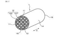
- FIG. 1 is a perspective view of the exhaust gas purification filter according to the first embodiment.
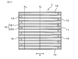
- FIG. 2 is a cross-sectional view taken along the filter axial direction of the exhaust gas purification filter according to the first embodiment.
- FIG. 3 is a diagram showing the flow of exhaust gas in the exhaust gas purification filter according to the first embodiment.
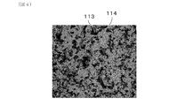
- FIG. 4 is a diagram showing an example of a reflected electron image of the partition wall surface obtained by a scanning electron microscope obtained when measuring the surface opening diameter of pores on the partition wall surface in the exhaust gas purification filter according to the first embodiment.
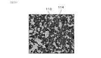
- FIG. 5 is a diagram showing an example of a binarized image obtained by binarizing the reflected electron image of FIG. 4.
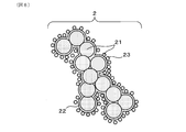
- FIG. 6 is a diagram schematically showing the microstructure of PM.
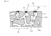
- FIG. 7 is an enlarged cross-sectional view of the partition wall on which the surface side of the partition wall into which the exhaust gas flows is shown.
- FIG. 8 is a diagram showing how PM is segregated in the vicinity of the surface opening in the partition wall shown in FIG. 7.
- FIG. 9 is a diagram showing how the ash contained in the PM remains after the PM shown in FIG. 8 is regenerated.
- FIG. 10 is a diagram showing how PM is collected again in the state where the residual ash content shown in FIG. 9 is present.
- FIG. 10 is a diagram showing how PM is collected again in the state where the residual ash content shown in FIG. 9 is present.
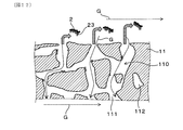
- FIG. 11 is a diagram showing a state in which ash crosslinks the surface openings of the pores on the partition wall surface by repeating the PM deposition and the PM regeneration process from the state of FIG.
- FIG. 12 is a diagram showing how the ash that crosslinks the surface opening shown in FIG. 11 is peeled off by the flow of exhaust gas, and the peeled ash is transported to the sealing portion on the gas outflow side.
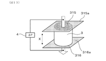
- FIG. 13 is a diagram showing a method of measuring the gas permeability coefficient of the exhaust gas purification filter.
- FIG. 14 (a) is a diagram showing an example of a tape for forming a sealing portion attached to the upstream end face of the measurement sample collected from the exhaust gas purification filter, and FIG.
- FIG. 14 (b) is a diagram showing an example of the tape for forming a sealing portion, and FIG. 14 (b) is from the exhaust gas purification filter. It is a figure which showed an example of the tape for forming a sealing part attached to the downstream end face of the collected measurement sample.
- FIG. 15 is a diagram showing an example of a relationship diagram between the gas flow velocity (X-axis) and the pressure loss (Y-axis).
- FIG. 16 is a diagram showing the relationship between the gas permeability coefficient ratio k c / k 10 and the pressure drop increase rate obtained in the experimental example.
- the exhaust gas purification filter 1 of the present embodiment is used by being arranged in an exhaust passage (not shown) of a gasoline engine. That is, the exhaust gas purification filter 1 is a gasoline particulate filter (GPF) capable of collecting PM2 (see FIG. 6 described later) discharged from the gasoline engine.
- GPF gasoline particulate filter
- the direction of the arrows on both ends shown in FIGS. 1 to 3 is defined as the filter axial direction X of the exhaust gas purification filter 1.
- the exhaust gas purification filter 1 has a partition wall 11, a plurality of cells 12, and a sealing portion 13. As illustrated in FIGS. 1 and 2, the partition wall 11 has, for example, a grid-like shape in a cross-sectional view perpendicular to the filter axial direction X inside the skin portion 14 formed in a cylindrical shape such as a cylinder. Can be provided to exhibit.
- the partition wall 11 and the skin portion 14 can be formed of, for example, cordierite or the like.
- the sealing portion 13 can be formed of, for example, ceramics such as cordierite, but may be made of other materials.
- the plurality of cells 12 are formed by being partitioned by a partition wall 11.
- the cell 12 is surrounded by the partition wall 11 to form a gas flow path.
- the extension direction of the cell 12 usually coincides with the filter axial direction X.
- the cell shape can be, for example, a quadrangular shape as illustrated in FIG.
- the cell shape is not limited to this, and may be, for example, a polygonal shape such as a triangular shape or a hexagonal shape, or a circular shape. Further, the cell shape may be composed of a combination of two or more different shapes.
- the plurality of cells 12 are alternately sealed by sealing portions 13 at both ends of the filter. Specifically, the plurality of cells 12 are first opened to the filter end face 15 (upstream end face) on the exhaust gas inflow side and closed by the sealing portion 13 on the filter end face 16 (downstream end face) on the exhaust gas outflow side. It can have a cell 121 and a second cell 122 which is open to the filter end face 16 on the exhaust gas outflow side and is closed by the sealing portion 13 on the filter end face 15 on the exhaust gas inflow side. As a result, as illustrated in FIG.
- the exhaust gas G that has flowed into the first cell 121 from the filter end surface 15 on the exhaust gas inflow side flows through the first cell 121 and also through the porous partition wall 11. It reaches 2 cells 122.
- the exhaust gas G that has reached the second cell 122 flows in the second cell 122 and is discharged from the filter end surface 16 on the exhaust gas outflow side.
- the first cell 121 and the second cell 122 are alternately arranged so as to be adjacent to each other, for example, in the horizontal direction orthogonal to the filter axial direction X and in the vertical direction orthogonal to both the filter axial direction X and the horizontal direction. It can be formed side by side. In this case, when the filter end face 15 on the exhaust gas inflow side or the filter end face 16 on the exhaust gas outflow side is viewed from the filter axial direction X, the first cell 121 and the second cell 122 are arranged in a check pattern, for example.
- the first cell 121 and the second cell 122 adjacent to each other are separated by a partition wall 11 in between.
- the partition wall 11 has a large number of pores 110 as illustrated in FIG. Specifically, the pore 110 in the partition wall 11 includes a communication hole 111 that communicates between the first cell 121 and the second cell 122 that are adjacent to each other. In addition to the communication holes 111, the pores 110 in the partition wall 11 may include non-communication holes 112 that do not communicate between the first cell 121 and the second cell 122 that are adjacent to each other.
- the average pore diameter of the partition wall 11 (that is, the average pore diameter inside the partition wall 11) is A ⁇ m
- the average pore diameter A is in the range of 5 ⁇ m or more and less than 15 ⁇ m.
- the average pore diameter A of the partition wall 11 is measured by a mercury porosimeter using the principle of the mercury intrusion method. Specifically, a test piece is cut out from the exhaust gas purification filter 1. However, the portion where the sealing portion 13 exists is excluded. The test piece is a rectangular parallelepiped having dimensions in the direction orthogonal to the filter axial direction X of 15 mm in length ⁇ 15 mm in width and a length of 20 mm in the filter axial direction X. Next, the test piece is stored in the measurement cell of the mercury porosimeter, and the pressure inside the measurement cell is reduced.
- the measurement is performed in the pressure range of 0.5 to 20000 psia.
- 0.5 psia corresponds to 0.35 ⁇ 10 -3 kg / mm 2
- 20000 psia corresponds to 14 kg / mm 2 .
- the range of the pore diameter corresponding to this pressure range is 0.01 to 420 ⁇ m.
- a contact angle of 140 ° and a surface tension of 480 dyn / cm are used.
- the average pore diameter A is a pore diameter (pore diameter at an integrated value of 50% of the pore volume) d 50 at which the cumulative pore volume is 50% in the pore diameter distribution of the partition wall 11.
- the average surface opening diameter of the pores 110 on the surface of the partition wall 11 is set to B ⁇ m.
- the ratio calculated by the formula of 100 ⁇ (AB) / B represented by the above-mentioned average pore diameter A and average surface opening diameter B is 30% or less.
- the average surface opening diameter B of the pores 110 on the surface of the partition wall 11 is measured as follows.
- a surface opening 113 is formed by pores 110 on the surface of the partition wall 11 on the side where the exhaust gas G flows in and the surface of the partition wall 11 on the side where the exhaust gas G flows out.
- a scanning electron microscope SEM
- the acceleration voltage can be 10 kV and the magnification can be 300 times.
- FIG. 4 shows an example of a reflected electron image on the surface of the partition wall 11. In the reflected electron image of FIG.
- the black region is the surface opening 113 on the surface of the partition wall 11
- the light gray region is the skeleton portion 114 on the surface of the partition wall 11.
- the binarization treatment aims to distinguish between the surface opening 113 on the surface of the partition wall 11 and the skeleton portion 114 on the surface of the partition wall 11. Since the surface opening 113 and the skeleton portion 114 have different brightnesses from each other, in the binarization process, noise remaining in the captured image is removed, and after setting an arbitrary threshold value, the binarization process is performed.
- FIG. 5 shows an example of a binarized image.
- the light gray region is the surface opening 113 on the surface of the partition wall 11
- the black region is the skeleton portion 114 on the surface of the partition wall 11.
- the equivalent circle diameter which is the diameter of a perfect circle having the same area as the surface opening 113, was calculated for each surface opening 113, and all the calculated circle equivalents were calculated.
- the value obtained by integrating the diameters and dividing by the number of surface openings 113 is taken as the surface opening diameter.
- the average value of each surface opening diameter obtained from each binarized image obtained for any five different locations on the partition wall 11 surface as described above is defined as the average surface opening diameter B of the pores 110 on the partition wall 11 surface. ..
- the value of the average pore diameter A of the partition wall 11 defined as described above is equal to or greater than the average surface opening diameter B of the pores 110 on the surface of the partition wall 11 (A ⁇ B). Further, the exhaust gas purification filter 1 has 100 ⁇ (A ⁇ ) represented by the value of the average pore diameter A of the partition wall 11, the average pore diameter A of the partition wall 11, and the average surface opening diameter B of the pores 110 on the surface of the partition wall 11.
- the ratios calculated by the formulas B) / B are within the specific ranges described above.
- PM2 contains solid carbon (suit) 21, which is the main component, as well as soluble organic component (SOF) 22, and ash (Ash) 23 derived from engine oil and the like.
- suitable solid carbon
- SOF soluble organic component
- Ash ash
- PM2 is collected as it passes through the pores 110 in the partition wall 11.
- the arrow in FIG. 7 indicates the flow of the exhaust gas G flowing in the pore 110.
- the surface opening 113 on the surface of the partition wall 11 is crosslinked by the ash 23 by repeating the deposition of PM2 containing the ash 23 and the regeneration process of PM2.
- the ash 23 that had crosslinked the surface opening 113 was peeled off during the regeneration of PM2 or the flow of the exhaust gas G, and the peeled ash 23 was the sealing portion 13 on the gas outflow side.
- the transported ash 23 is deposited on the most downstream portion 10 of the filter (see FIG. 3, which can also be referred to as the bottom portion of the filter).
- the ash 23 covering the outer surface of the partition wall 11 increases the pressure loss, but the ash 23 deposited on the most downstream portion 10 of the filter does not easily increase the pressure loss.
- the ash content 23 is crosslinked at the surface opening 113 of the partition wall 11, and the ash content 23 is likely to be peeled off. As a result, it is possible to increase the amount of ash 23 deposited on the most downstream portion 10 of the filter rather than the ash 23 covering the outer surface of the partition wall 11.
- the above mechanism makes it possible not only to secure the initial PM collection rate of the exhaust gas purification filter 1 and to reduce the initial pressure loss, but also to suppress the increase in pressure loss after the ash 23 is deposited.
- the average pore diameter A of the partition wall 11 when the average pore diameter A of the partition wall 11 is less than 5 ⁇ m, the initial pressure drop reduction effect is diminished, and the pressure loss after the ash 23 is deposited tends to increase.
- the average pore diameter A of the partition wall 11 is 15 ⁇ m or more, the initial PM collection performance is lowered, and the pressure loss after the ash 23 is deposited tends to increase.
- the ratio calculated by the formula of 100 ⁇ (AB) / B exceeds 30%, the difference between the average pore diameter A and the average surface opening diameter B becomes large, and the ash content 23 is reduced.
- the PM2 contained therein is likely to be deposited inside the partition wall 11, and the ash 23 is difficult to be peeled off, resulting in an increase in pressure loss due to the ash 23 remaining accumulated due to the aged use of the vehicle.
- the exhaust gas purification filter 1 satisfies A ⁇ B as described above, the surface opening diameter of the pores 110 on the surface of the partition wall 11 is smaller than the pore diameter inside the partition wall 11, and 100 ⁇ ( The ratio calculated by the formula AB) / B is 0% or more.
- the surface opening ratio of the pores 110 on the surface of the partition wall 11 on the side where the exhaust gas G flows in can be 25% or more and 40% or less.
- the surface opening ratio of the pores 110 on the surface of the partition wall 11 By setting the surface opening ratio of the pores 110 on the surface of the partition wall 11 to 25% or more, the number of surface openings serving as the inlet of the exhaust gas G into the partition wall 11 increases, and the flow velocity of the exhaust gas G becomes slow, so that the initial pressure loss is reduced. It becomes easier to obtain the effect.
- PM2 containing the ash content 23 is less likely to be deposited inside the partition wall 11, and it is easy to suppress an increase in pressure loss after the ash content 23 is deposited.
- the surface aperture ratio of the pores 110 on the surface of the partition wall 11 is an expression of 100 ⁇ (total value of the area of each surface opening 113 in all the above-mentioned binarized images) / (total value of the area of all the binarized images). Can be calculated from. All binarized images mean the above-mentioned five binarized images.
- the porosity of the partition wall 11 can be 50% or more and 70% or less.
- the porosity of the partition wall 11 can be preferably 52% or more, more preferably 60% or more, from the viewpoint of reducing initial pressure loss and the like.
- the porosity of the partition wall 11 can be preferably 68% or less, more preferably 67% or less, still more preferably 66% or less, from the viewpoint of improving the strength of the exhaust gas purification filter 1.
- the upper and lower limits can be arbitrarily combined.
- the pore diameter at which the cumulative pore volume in the pore diameter distribution of the partition wall 11 by the mercury porosimeter using the principle of the mercury injection method described above is 75% (pore diameter at an integrated value of 75% of the pore volume) d 75.
- the exhaust gas purification filter 1 shall satisfy XY ⁇ 7 ⁇ m, where X ⁇ m and the pore diameter (pore diameter at the integrated value of 25% of the pore volume) d 25 where the cumulative pore volume is 25% are Y ⁇ m. Can be done. According to this configuration, the flow velocity of the exhaust gas G tends to be uniform, and it is possible to ensure the suppression of the increase in pressure loss after the accumulation of ash.
- XY can be preferably 6.8 ⁇ m or less, more preferably 6.5 ⁇ m or less, from the viewpoint of suppressing an increase in pressure loss after ash accumulation. From the viewpoint of cost and the like, XY can be preferably 3.5 ⁇ m or more, more preferably 5.0 ⁇ m or more.
- the exhaust gas purification filter 1 sets the gas permeability coefficient of the partition wall 11 at the position X 10 (see FIG. 2) 10 mm from the filter end face 15 on the exhaust gas inflow side in a state where the ash 23 of 20 g / L or more and 40 g / L or less is deposited.
- the gas permeability coefficient of the partition wall at the center position X C (see FIG. 2) between the filter end face 16 of the filter end face 15 and the exhaust gas outflow side of the exhaust gas inlet side was set to k c
- the value of k 10 can be 1.5 or less. According to this configuration, it is possible to ensure the suppression of the increase in pressure loss after ash accumulation.
- the accumulated amount of ash 23 is set to 20 g / L or more.
- the accumulated amount of the ash 23 is set to 40 g / L or less.
- k c / k 10 is an index showing the magnitude relationship between the gas permeability coefficient k c and the gas permeability coefficient k 10 .
- the gas permeability coefficient of the partition wall 11 decreases as the ash content 23 accumulates.
- the flow velocity of the exhaust gas G introduced into the cell 12 of the exhaust gas purification filter 1 is such that the filter end face 15 on the exhaust gas inflow side and the filter on the exhaust gas outflow side are located at the position X10 10 mm from the filter end face 15 on the exhaust gas inflow side. faster than the center position X C between the end face 16.
- the amount of ash 23 deposited at the position X 10 10 mm from the filter end face 15 on the exhaust gas inflow side is larger than that at the central position X C between the filter end face 15 on the exhaust gas inflow side and the filter end face 16 on the exhaust gas outflow side.
- the relationship between the gas permeability coefficient k 10 and the gas permeability coefficient k c after the ash 23 is deposited is larger in the gas permeability coefficient k c than in the gas permeability coefficient k 10 . That is, in the conventional exhaust gas purification filter not provided with the configuration of the present disclosure, the value of k c / k 10 is usually large.
- the value of k c / k 10 exceeds 1.5, the rate of increase in pressure drop after the accumulation of ash 23 with respect to the initial pressure drop becomes high, which is not preferable. It is considered that this is because the ash 23 on the surface of the partition wall 11 at the position X 10 10 mm from the filter end surface 15 on the exhaust gas inflow side is not peeled off and is deposited in the pores 110. Therefore, in order to suppress the pressure drop increase rate, the value of k c / k 10 is preferably 1.5 or less.
- the gas permeability coefficients k 10 and k c are measured as follows. First, an ash content 23 of 20 g / L or more and 40 g / L or less is deposited on the exhaust gas purification filter 1.
- the ash 23 can be deposited by operating a gasoline engine using gasoline containing 2% of ash derived from engine oil and depositing the ash on the exhaust gas purification filter 1 mounted on the exhaust passage. Specifically, (1) PM2 is deposited under the condition of (1) a stoichiometric atmosphere and the center temperature of the exhaust gas purification filter 1 at 800 ° C. for 9 minutes, and (2) the center temperature of the exhaust gas purification filter 1 is 800 ° C. PM2 is regenerated at ⁇ 900 ° C. for 1 minute.
- the ash content 23 is deposited on the exhaust gas purification filter 1.
- the accumulated amount of the ash content 23 can be grasped by appropriately taking out the exhaust gas purification filter 1 and measuring the weight.
- each measurement sample is a cylindrical shape having a diameter of 30 mm and a length of 25 mm in the filter axial direction.
- the skin portion 14 of each hollowed-out measurement sample can be formed by, for example, cementing.
- polyester tapes 315a and 316a are attached to both end faces 315 and 316 of the measurement sample 3 in the filter axial direction X, respectively.
- the polyester tapes 315a and 316a are partially eliminated by, for example, a soldering iron so that the alternating sealing portions 13 are formed by the polyester tapes 315a and 316a.
- 13 cells 12 are opened and the remaining cells 12 are opened as illustrated in FIG. 14A. It is closed by a sealing portion 13 made of polyester tape 315a.
- the downstream end surface 316 which is the exhaust gas outflow side filter end surface in the measurement sample 3
- 24 cells 12 are opened and the remaining cells 12 are made of polyester tape 316a as illustrated in FIG. 14 (b).
- the sealing portion 13 is closed. That is, instead of the sealing portion 13 made of ceramics, the sealing portion 13 made of polyester tapes 315a and 316a is formed.
- the measurement sample 3 in which the sealing portion 13 is formed by the polyester tapes 315a and 316a has been described here, but the measurement sample 3 in which the sealing portion 13 made of ceramics is formed may also be used. Similar results are obtained.
- gas is flowed from the upstream end surface 315 of the measurement sample 3 toward the downstream end surface 316 of the measurement sample 3, and the relationship between the gas flow velocity and the pressure loss is measured by the palm pollometer 4.
- the pressure loss when the gas flow velocity is changed is measured.
- the arrow in FIG. 13 indicates the gas flow.
- the relationship diagram between the gas flow velocity (X-axis) and the pressure loss (Y-axis) is obtained.
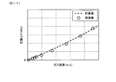
- FIG. 15 shows an example of a relationship diagram between the gas flow velocity (X-axis) and the pressure loss (Y-axis).
- the measured value (plot point) by the palm pollometer 4 and the calculated value (broken line) obtained by the following equations (i) to (viii) are shown.
- the equations (i) to (viii) will be described below.
- ⁇ P inlet / exit the opening area A open (unit: m 2 ) of the cell 12
- the opening area A in (unit: m 2 ) of the cell 12 at the filter end face 15 on the exhaust gas inflow side and the gas flow velocity in the cell 12.
- the V channel (unit: m / s) and the air density ⁇ (unit: kg / m 3 ) satisfy the relationship of the following equation (ii).
- ⁇ P channel + ⁇ P wall a gas permeation coefficient k (unit: m 2 ), a length L (unit: m) of the filter axial direction X of the exhaust gas purification filter 1, and a hydraulic diameter a 1 (unit: m) of the cell 12.
- m) the thickness w (unit: m) of the partition wall 11, the friction coefficient F (unit: dimensionless) in the cell 12, the Reynolds number (unit: dimensionless), and the gas viscosity ⁇ (unit: Pa ⁇ s).
- the gas flow velocity V channel (unit: m / s) in the cell 12 satisfy the relationship of the following equations (iii) to (viii).
- equation (iii) e is an exponential function exp.
- the pressure drop value is calculated based on the above formulas (i) to (viii).
- the dashed line based on the calculated value shown in the relationship diagram between the gas flow velocity (X-axis) and the pressure loss (Y-axis) illustrated in FIG. 15 is the pressure loss value obtained by calculation.
- the pressure drop value measures the filter length L, the cell opening area A open , the hydraulic diameter a 1 , and the thickness w of the partition wall 11, excluding the gas permeability coefficient k. These values do not change even if the gas flow velocity is changed. Therefore, by inputting an arbitrary value to the gas permeability coefficient, the calculated value in the relationship diagram between the gas flow velocity (X-axis) and the pressure loss (Y-axis) can be derived.
- the gas permeability coefficient k is a value obtained by back-calculating the gas permeability coefficient from the measured values of the pressure loss measured by the palm polo meter from the equations (i) to (viii). As described above, the gas permeability coefficients k 10 and k c at a predetermined position in a state where a predetermined amount of ash is deposited can be obtained.
- the exhaust gas purification filter 1 described above can exert a sufficient effect when used in a state where the catalyst is not supported on the partition wall 11.
- Example 1 -Manufacturing of exhaust gas purification filter- (Example 1)
- porous silica (Si source), talc (Mg source), and aluminum hydroxide (Al source) are blended so as to have the blending ratio (mass%) shown in Table 1.
- a raw material for forming talc was prepared.
- the bulk density of the porous silica used is 0.18 g / cm 3 .
- a tap densor manufactured by Seishin Enterprise Co., Ltd. which is a tap density method fluidity adhesive force measuring instrument, was used. Specifically, after filling the cylinder of the measuring instrument with silica, the silica was compressed by tapping, and the bulk density was calculated from the mass of the compressed silica and the volume of the cylinder. Further, as the aluminum hydroxide, one having an average particle diameter of 3 ⁇ m and one having an average particle diameter of 8 ⁇ m were used.
- the "average particle size” refers to the particle size when the volume integrated value in the particle size distribution obtained by the laser diffraction / scattering method is 50%.
- solvent Water (solvent), methyl cellulose (binder), and a dispersant are added to the cordierite forming raw material so as to have the blending ratio (mass%) shown in Table 1, and the mixture is mixed by a kneader to form the cordierite forming raw material.
- a solvent containing the above was prepared.
- the dispersant mainly suppresses agglomeration of particles and improves solvability.
- polyoxyethylene polyoxypropylene glyceryl ether having an average molecular weight of 4550 was used.
- the soil density deviation rate was introduced as a new index of particle dispersibility in the kneaded soil.
- the clay before extrusion molding is taken out with a mold, and the clay at eight places is randomly taken out.
- the extracted clay was put into a measuring instrument with a diameter of 25 mm and a length of 20 mm in the pressure measuring instrument "Autograph" manufactured by Shimadzu Corporation, and the volume of the earth and the soil taken out by compressing with a pressurization of 1 kN. Calculate the clay density from the weight.
- the average value of the soil density calculated for the eight soils is taken as the measured soil density.
- the clay density calculated in advance from the mixing ratio of the raw materials is defined as the calculated clay density.
- the particle dispersibility it is possible to judge the particle dispersibility by confirming the difference (deviation rate) of the soil density measured with respect to the soil density calculated by this calculation. As the measured soil density becomes smaller than the calculated soil density, the wettability of the dispersant is poor and more air is present on the particle surface, resulting in poor particle dispersibility. On the other hand, the closer the measured soil density is to the calculated value of the soil density, the better the particle dispersibility.
- Example 1 the speed of the kneader and the number of times the kneading machine was repeatedly passed through the kneading machine were arbitrarily changed to use the kneading soil adjusted so that the following kneading density deviation rate was less than 10%.
- the soil density deviation rate tends to decrease.
- the clay prepared as described above was formed into a honeycomb shape by extrusion molding.
- the molded product was cut to a predetermined length after drying.
- the molded product was fired at 1430 ° C. to obtain a sintered body having a honeycomb structure.
- the exhaust gas inflow end face and the exhaust gas outflow end face of the cell were alternately filled and fired with a slurry containing a ceramic raw material of the same type as the sintered body having a honeycomb structure to form a sealed portion.
- Example 2 In Example 1, the average particle size and bulk density of the porous silica in the cordierite forming raw material were changed. The larger the average particle size of the porous silica, the larger the porosity of the formed partition wall, and the smaller the bulk density of the porous silica, the higher the porosity of the formed partition wall. Further, when the proportion of the particle size is increased in the compounding of aluminum hydroxide having different particle size, the surface aperture ratio and the average surface opening diameter become large. Further, by increasing the rate of temperature rise between 1200 ° C. and 1430 ° C. during firing, the pore diameter and the average surface opening diameter can be increased. It was prepared by combining these conditions.
- the total blending ratio of aluminum hydroxide was the same as that of Example 1, the blending of aluminum hydroxide having different particle sizes was changed, and the blending ratio of other clay was the same as that of Example 1. Then, in the same manner as in Example 1, the speed of the kneader and the number of times the clay is repeatedly passed through the kneader are arbitrarily changed to use the clay adjusted so that the clay density deviation rate is less than 10%.
- the exhaust gas purification filters of Examples 2 to 8 were produced by changing the heating rate between 1200 ° C. and 1430 ° C. during firing.
- Example 9 In Example 1, the average particle size and bulk density of the porous silica in the cordierite forming raw material are changed, and the speed of the kneader and the number of times the clay is repeatedly passed through the kneader are arbitrarily changed to dissociate the clay density.
- the exhaust gas purification filter of Example 9 was produced by using silica soil adjusted so that the rate was 10% or more.
- the bulk density of the porous silica used is 0.25 g / cm 3 .
- Example 10 Example 9
- Example 9 the average particle size and bulk density of the porous silica in the cordierite forming raw material were changed.
- the exhaust gas purification filters of Examples 10 and 11 were produced by adjusting the soil so that the soil density deviation rate was 10% or more in the same manner as in Example 9.
- Comparative Example 1 In producing the exhaust gas purification filter of Comparative Example 1, fused silica (Si source), talc (Mg source), and aluminum hydroxide (Al source) are blended so as to have the blending ratio (mass%) shown in Table 2. To prepare a raw material for forming talc. The bulk density of the molten silica used is 1.30 g / cm 3 .
- lubricating oil Water (solvent), methyl cellulose (binder), lubricating oil, and graphite are added to the cordierite forming raw material so as to have the blending ratios shown in Table 2, and mixed by a kneader to contain the cordierite forming raw material.
- Graphite was prepared.
- the purpose of the lubricating oil is to improve the slippage of the clay, the molding machine and the metal part on the surface of the mold to increase the molding speed.
- rapeseed oil which is a vegetable oil
- the clay density deviation rate was adjusted to be less than 10% by arbitrarily changing the speed of the kneader and the number of times the clay was repeatedly passed through the kneader.
- the exhaust gas purification filter of Comparative Example 1 was produced in the same manner as in Example 1 thereafter.
- Comparative Example 2 Comparative Example 3
- Comparative Example 3 the average particle size of molten silica and talc and the blending ratio of graphite in the cordierite forming raw material were changed.
- the exhaust gas purification filters of Comparative Example 2 and Comparative Example 3 were produced by adjusting the soil so that the soil density deviation rate was less than 10% in the same manner as in Comparative Example 1.
- Comparative Example 4 In producing the exhaust gas purification filter of Comparative Example 4, porous silica (Si source), talc (Mg source), and aluminum hydroxide (Al source) are blended so as to have the blending ratio (mass%) shown in Table 3. As a result, a raw material for forming talc was prepared. The bulk density of the porous silica used is 0.25 g / cm 3 .
- Water (solvent), methylcellulose (binder), and lubricating oil are added to the cordierite-forming raw material so as to have the blending ratios shown in Table 3, and the clay is mixed with a kneader to contain the cordierite-forming raw material.
- the lubricating oil rapeseed oil, which is the same vegetable oil as above, was used.
- the soil density deviation rate was adjusted to be 10% or more by arbitrarily changing the speed of the kneader and the number of times the soil was repeatedly passed through the kneader.
- the exhaust gas purification filter of Comparative Example 4 was produced in the same manner as in Example 1 thereafter.
- Comparative Example 5 Comparative Example 6
- Comparative Example 4 the average particle size and bulk density of the porous silica in the cordierite forming raw material were changed.
- the exhaust gas purification filters of Comparative Example 5 and Comparative Example 6 were produced by adjusting the soil so that the soil density deviation rate was 10% or more in the same manner as in Comparative Example 4.
- partition wall characteristics of the exhaust gas purification filters of Examples and Comparative Examples were measured. Specifically, according to the measurement method described above, the average pore diameter A of the partition wall, XY (pore diameter d 75 -pore diameter d 25 ) in the pore diameter distribution of the partition wall, and the porosity of the partition wall were measured. At this time, an Autopore IV9500 manufactured by Shimadzu Corporation was used as the mercury porosimeter. Further, according to the measurement method described above, the average surface opening diameter B of the pores on the partition wall surface and the surface opening ratio of the pores on the partition wall surface were measured. At this time, Quanta250FEG manufactured by FEI was used as the SEM.
- the image analysis software includes WinROOF Ver. From Mitani Corporation. 7.4 was used. Further, the ratio calculated by the formula of 100 ⁇ (AB) / B was calculated from the average pore diameter A of the obtained partition wall and the average surface opening diameter B of the pores on the partition wall surface. Further, the value of the gas permeability coefficient ratio k c / k 10 was measured according to the above-mentioned measuring method. At this time, CEP-1100AXSHJ manufactured by Porous Materials was used as the palm porometer.
- the initial PM collection rate, initial pressure loss, and pressure loss after ash accumulation were measured.
- the initial PM collection rate, initial pressure drop, and pressure loss after ash accumulation are ⁇ 118.4 mm (filter diameter) x L120 mm (filter length), the bulkhead thickness is 8.5 mil, and the number of cells is 300 cpsi.
- An exhaust gas purification filter having a certain cell structure was used.
- the initial PM collection rate was measured as follows.
- the produced exhaust gas purification filter was installed in the exhaust pipe of a gasoline direct injection engine, and exhaust gas containing PM was allowed to flow through the exhaust gas purification filter.
- N in which is the number of PMs in the exhaust gas before flowing into the exhaust gas purification filter
- N out which is the number of PMs in the exhaust gas flowing out from the exhaust gas purification filter
- the initial PM collection rate was calculated from the N in formula.
- the measurement conditions were a temperature of 450 ° C. and an exhaust gas flow rate of 2.8 m 3 / min.
- a PM particle number counter "AVL-489" manufactured by AVL was used for the measurement of the PM number.
- the initial pressure drop was measured as follows. At the same time as the measurement of the initial PM collection rate, the pressure before the exhaust gas purification filter (upstream) and the pressure after the exhaust gas purification filter (downstream) were measured by the pressure sensor, and the difference was taken as the initial pressure loss. At this time, the measurement conditions were a temperature of 720 ° C. and an exhaust gas flow rate of 11.0 m 3 / min. For each measurement, each exhaust gas purification filter in the initial state in which PM was not deposited and in which the catalyst was not coated was used.
- the case where the initial PM collection rate was 80% or more was designated as "A” because the initial PM collection rate was sufficiently secured.
- the case where the initial PM collection rate was 70% or more and less than 80% was designated as “B” as the initial PM collection rate was secured.
- the initial PM collection rate was less than 70% it was designated as “C” because the initial PM collection rate was not secured.
- the case where the initial pressure loss was 6 kPa or less was designated as “A” because the effect of reducing the initial pressure loss was sufficiently obtained.
- the initial pressure loss was more than 6 kPa and 7 kPa or less, it was designated as "B” because the effect of reducing the initial pressure drop was obtained.
- the initial pressure drop was more than 8 kPa it was designated as "C” because the effect of reducing the initial pressure drop was not obtained.
- Ash was deposited on the exhaust gas purification filter by repeating the PM regeneration process of regenerating the PM at 800 ° C. to 900 ° C. for 1 minute. At this time, the accumulated amount of ash was grasped by taking out an exhaust gas purification filter and measuring the weight as appropriate. After that, the pressure before the exhaust gas purification filter and the pressure after the exhaust gas purification filter were measured by the pressure sensor in the same manner as the above initial pressure loss, and the difference was taken as the pressure loss after the ash accumulation. In this experimental example, when the pressure loss after ash deposition when 30 g / L of ash is deposited is 11 kPa or less, it is considered that the effect of suppressing the increase in pressure loss after ash accumulation is sufficiently obtained. And said.
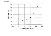
- FIG. 16 shows the relationship between the gas permeability coefficient ratio k c / k 10 and the pressure drop increase rate.
- FIG. 16 shows the result of the exhaust gas purification filter of Example 4 as a representative example of each Example.
- the ratio calculated by the formula of 100 ⁇ (AB) / B is 30% or less, and ash is contained by setting A ⁇ B. It can be seen that PM is less likely to be deposited inside the partition wall, and it becomes easier to suppress an increase in pressure loss due to the accumulated residual ash during aged use of the vehicle. Further, when the exhaust gas purification filters of Examples 1 to 8 and the exhaust gas purification filters of Examples 9 to 11 are compared, the initial PM collection rate is secured and the initial PM collection rate is secured by satisfying XY ⁇ 7 ⁇ m. It can be seen that the pressure loss reduction effect of
- the exhaust gas purification filters of Examples 1 to 11 have a gas permeability coefficient ratio of k c / k 10 of 1.5 or less in a state where ash content of 20 g / L or more and 40 g / L or less is deposited. According to this configuration, as shown in FIG. 16, it can be said that the suppression of the pressure drop increase after the ash accumulation can be ensured.
Landscapes
- Chemical & Material Sciences (AREA)
- Engineering & Computer Science (AREA)
- Ceramic Engineering (AREA)
- Chemical Kinetics & Catalysis (AREA)
- Manufacturing & Machinery (AREA)
- Physics & Mathematics (AREA)
- Geometry (AREA)
- Materials Engineering (AREA)
- Structural Engineering (AREA)
- Organic Chemistry (AREA)
- Mechanical Engineering (AREA)
- Combustion & Propulsion (AREA)
- General Engineering & Computer Science (AREA)
- Inorganic Chemistry (AREA)
- Geology (AREA)
- Health & Medical Sciences (AREA)
- Toxicology (AREA)
- Life Sciences & Earth Sciences (AREA)
- Filtering Materials (AREA)
- Processes For Solid Components From Exhaust (AREA)
- Filtering Of Dispersed Particles In Gases (AREA)
- Exhaust Gas After Treatment (AREA)
- Porous Artificial Stone Or Porous Ceramic Products (AREA)
Priority Applications (2)
| Application Number | Priority Date | Filing Date | Title |
|---|---|---|---|
| CN202080017648.3A CN113507974B (zh) | 2019-03-29 | 2020-02-18 | 废气净化过滤器 |
| EP20784174.3A EP3919154B1 (en) | 2019-03-29 | 2020-02-18 | Exhaust gas purification filter and its use in an exhaust passage of a gasoline engine |
Applications Claiming Priority (2)
| Application Number | Priority Date | Filing Date | Title |
|---|---|---|---|
| JP2019-068162 | 2019-03-29 | ||
| JP2019068162A JP6984961B2 (ja) | 2019-03-29 | 2019-03-29 | 排ガス浄化フィルタ |
Publications (1)
| Publication Number | Publication Date |
|---|---|
| WO2020202847A1 true WO2020202847A1 (ja) | 2020-10-08 |
Family
ID=72667870
Family Applications (1)
| Application Number | Title | Priority Date | Filing Date |
|---|---|---|---|
| PCT/JP2020/006164 Ceased WO2020202847A1 (ja) | 2019-03-29 | 2020-02-18 | 排ガス浄化フィルタ |
Country Status (4)
| Country | Link |
|---|---|
| EP (1) | EP3919154B1 (enExample) |
| JP (1) | JP6984961B2 (enExample) |
| CN (1) | CN113507974B (enExample) |
| WO (1) | WO2020202847A1 (enExample) |
Citations (6)
| Publication number | Priority date | Publication date | Assignee | Title |
|---|---|---|---|---|
| WO2004113252A1 (ja) * | 2003-06-23 | 2004-12-29 | Ibiden Co., Ltd. | ハニカム構造体 |
| WO2007097056A1 (ja) * | 2006-02-23 | 2007-08-30 | Ibiden Co., Ltd. | ハニカム構造体および排ガス浄化装置 |
| JP2012206061A (ja) * | 2011-03-30 | 2012-10-25 | Ngk Insulators Ltd | ハニカム構造体 |
| WO2013145314A1 (ja) * | 2012-03-30 | 2013-10-03 | イビデン株式会社 | ハニカムフィルタ |
| JP2013202503A (ja) * | 2012-03-28 | 2013-10-07 | Ngk Insulators Ltd | ハニカム構造体及びその製造方法 |
| JP2014505646A (ja) * | 2010-11-29 | 2014-03-06 | コーニング インコーポレイテッド | 多孔質セラミックハニカム物品およびその作製方法 |
Family Cites Families (8)
| Publication number | Priority date | Publication date | Assignee | Title |
|---|---|---|---|---|
| JP5444716B2 (ja) * | 2006-11-30 | 2014-03-19 | 日立金属株式会社 | セラミックハニカムフィルタ及びその製造方法 |
| JP5726414B2 (ja) * | 2009-11-18 | 2015-06-03 | 日本碍子株式会社 | 触媒担持フィルタ、及び排ガス浄化システム |
| US8821609B2 (en) * | 2010-04-01 | 2014-09-02 | Hitachi Metals, Ltd. | Ceramic honeycomb filter and its production method |
| JP5990095B2 (ja) * | 2012-12-18 | 2016-09-07 | 日本碍子株式会社 | 微粒子捕集フィルタ |
| JP6451615B2 (ja) * | 2015-01-09 | 2019-01-16 | 株式会社デンソー | 排ガスフィルタ |
| JP6227585B2 (ja) * | 2015-03-31 | 2017-11-08 | 日本碍子株式会社 | ハニカム構造体、及びハニカム構造体の製造方法 |
| CA2987427A1 (en) * | 2015-06-02 | 2016-12-08 | Scientific Design Company, Inc. | Epoxidation process |
| JP6693477B2 (ja) * | 2017-06-13 | 2020-05-13 | 株式会社デンソー | 排ガス浄化フィルタ |
-
2019
- 2019-03-29 JP JP2019068162A patent/JP6984961B2/ja not_active Expired - Fee Related
-
2020
- 2020-02-18 WO PCT/JP2020/006164 patent/WO2020202847A1/ja not_active Ceased
- 2020-02-18 EP EP20784174.3A patent/EP3919154B1/en active Active
- 2020-02-18 CN CN202080017648.3A patent/CN113507974B/zh active Active
Patent Citations (6)
| Publication number | Priority date | Publication date | Assignee | Title |
|---|---|---|---|---|
| WO2004113252A1 (ja) * | 2003-06-23 | 2004-12-29 | Ibiden Co., Ltd. | ハニカム構造体 |
| WO2007097056A1 (ja) * | 2006-02-23 | 2007-08-30 | Ibiden Co., Ltd. | ハニカム構造体および排ガス浄化装置 |
| JP2014505646A (ja) * | 2010-11-29 | 2014-03-06 | コーニング インコーポレイテッド | 多孔質セラミックハニカム物品およびその作製方法 |
| JP2012206061A (ja) * | 2011-03-30 | 2012-10-25 | Ngk Insulators Ltd | ハニカム構造体 |
| JP2013202503A (ja) * | 2012-03-28 | 2013-10-07 | Ngk Insulators Ltd | ハニカム構造体及びその製造方法 |
| WO2013145314A1 (ja) * | 2012-03-30 | 2013-10-03 | イビデン株式会社 | ハニカムフィルタ |
Non-Patent Citations (1)
| Title |
|---|
| See also references of EP3919154A4 * |
Also Published As
| Publication number | Publication date |
|---|---|
| EP3919154B1 (en) | 2023-11-22 |
| EP3919154A1 (en) | 2021-12-08 |
| EP3919154A8 (en) | 2022-03-16 |
| CN113507974A (zh) | 2021-10-15 |
| CN113507974B (zh) | 2023-01-17 |
| EP3919154A4 (en) | 2022-04-06 |
| JP6984961B2 (ja) | 2021-12-22 |
| JP2020165397A (ja) | 2020-10-08 |
Similar Documents
| Publication | Publication Date | Title |
|---|---|---|
| JP6693477B2 (ja) | 排ガス浄化フィルタ | |
| US11878263B2 (en) | Exhaust gas purification filter | |
| CN113646511B (zh) | 废气净化过滤器 | |
| WO2020202848A1 (ja) | 排ガス浄化フィルタ | |
| JP6940786B2 (ja) | 排ガス浄化フィルタ | |
| CN113766974B (zh) | 废气净化过滤器 | |
| WO2016111287A1 (ja) | 排ガスフィルタ | |
| JP6984961B2 (ja) | 排ガス浄化フィルタ | |
| CN218816601U (zh) | 蜂窝过滤器 | |
| CN115501709B (zh) | 蜂窝过滤器 | |
| JP7002503B2 (ja) | 排ガス浄化フィルタ | |
| JP7002504B2 (ja) | 排ガス浄化フィルタ | |
| JP6947200B2 (ja) | 排ガス浄化フィルタ |
Legal Events
| Date | Code | Title | Description |
|---|---|---|---|
| 121 | Ep: the epo has been informed by wipo that ep was designated in this application |
Ref document number: 20784174 Country of ref document: EP Kind code of ref document: A1 |
|
| ENP | Entry into the national phase |
Ref document number: 2020784174 Country of ref document: EP Effective date: 20210831 |
|
| NENP | Non-entry into the national phase |
Ref country code: DE |