WO2020202847A1 - 排ガス浄化フィルタ - Google Patents
排ガス浄化フィルタ Download PDFInfo
- Publication number
- WO2020202847A1 WO2020202847A1 PCT/JP2020/006164 JP2020006164W WO2020202847A1 WO 2020202847 A1 WO2020202847 A1 WO 2020202847A1 JP 2020006164 W JP2020006164 W JP 2020006164W WO 2020202847 A1 WO2020202847 A1 WO 2020202847A1
- Authority
- WO
- WIPO (PCT)
- Prior art keywords
- exhaust gas
- partition wall
- gas purification
- purification filter
- ash
- Prior art date
Links
Images


Classifications
-
- F—MECHANICAL ENGINEERING; LIGHTING; HEATING; WEAPONS; BLASTING
- F01—MACHINES OR ENGINES IN GENERAL; ENGINE PLANTS IN GENERAL; STEAM ENGINES
- F01N—GAS-FLOW SILENCERS OR EXHAUST APPARATUS FOR MACHINES OR ENGINES IN GENERAL; GAS-FLOW SILENCERS OR EXHAUST APPARATUS FOR INTERNAL COMBUSTION ENGINES
- F01N3/00—Exhaust or silencing apparatus having means for purifying, rendering innocuous, or otherwise treating exhaust
- F01N3/02—Exhaust or silencing apparatus having means for purifying, rendering innocuous, or otherwise treating exhaust for cooling, or for removing solid constituents of, exhaust
- F01N3/021—Exhaust or silencing apparatus having means for purifying, rendering innocuous, or otherwise treating exhaust for cooling, or for removing solid constituents of, exhaust by means of filters
-
- B—PERFORMING OPERATIONS; TRANSPORTING
- B01—PHYSICAL OR CHEMICAL PROCESSES OR APPARATUS IN GENERAL
- B01D—SEPARATION
- B01D39/00—Filtering material for liquid or gaseous fluids
- B01D39/14—Other self-supporting filtering material ; Other filtering material
- B01D39/20—Other self-supporting filtering material ; Other filtering material of inorganic material, e.g. asbestos paper, metallic filtering material of non-woven wires
- B01D39/2068—Other inorganic materials, e.g. ceramics
- B01D39/2072—Other inorganic materials, e.g. ceramics the material being particulate or granular
- B01D39/2079—Other inorganic materials, e.g. ceramics the material being particulate or granular otherwise bonded, e.g. by resins
-
- B—PERFORMING OPERATIONS; TRANSPORTING
- B01—PHYSICAL OR CHEMICAL PROCESSES OR APPARATUS IN GENERAL
- B01D—SEPARATION
- B01D46/00—Filters or filtering processes specially modified for separating dispersed particles from gases or vapours
- B01D46/24—Particle separators, e.g. dust precipitators, using rigid hollow filter bodies
- B01D46/2403—Particle separators, e.g. dust precipitators, using rigid hollow filter bodies characterised by the physical shape or structure of the filtering element
- B01D46/2418—Honeycomb filters
- B01D46/2425—Honeycomb filters characterized by parameters related to the physical properties of the honeycomb structure material
- B01D46/2429—Honeycomb filters characterized by parameters related to the physical properties of the honeycomb structure material of the honeycomb walls or cells
-
- B—PERFORMING OPERATIONS; TRANSPORTING
- B01—PHYSICAL OR CHEMICAL PROCESSES OR APPARATUS IN GENERAL
- B01D—SEPARATION
- B01D46/00—Filters or filtering processes specially modified for separating dispersed particles from gases or vapours
- B01D46/24—Particle separators, e.g. dust precipitators, using rigid hollow filter bodies
- B01D46/2403—Particle separators, e.g. dust precipitators, using rigid hollow filter bodies characterised by the physical shape or structure of the filtering element
- B01D46/2418—Honeycomb filters
- B01D46/2425—Honeycomb filters characterized by parameters related to the physical properties of the honeycomb structure material
- B01D46/24492—Pore diameter
-
- B—PERFORMING OPERATIONS; TRANSPORTING
- B01—PHYSICAL OR CHEMICAL PROCESSES OR APPARATUS IN GENERAL
- B01D—SEPARATION
- B01D46/00—Filters or filtering processes specially modified for separating dispersed particles from gases or vapours
- B01D46/24—Particle separators, e.g. dust precipitators, using rigid hollow filter bodies
- B01D46/2403—Particle separators, e.g. dust precipitators, using rigid hollow filter bodies characterised by the physical shape or structure of the filtering element
- B01D46/2418—Honeycomb filters
- B01D46/2498—The honeycomb filter being defined by mathematical relationships
-
- C—CHEMISTRY; METALLURGY
- C04—CEMENTS; CONCRETE; ARTIFICIAL STONE; CERAMICS; REFRACTORIES
- C04B—LIME, MAGNESIA; SLAG; CEMENTS; COMPOSITIONS THEREOF, e.g. MORTARS, CONCRETE OR LIKE BUILDING MATERIALS; ARTIFICIAL STONE; CERAMICS; REFRACTORIES; TREATMENT OF NATURAL STONE
- C04B35/00—Shaped ceramic products characterised by their composition; Ceramics compositions; Processing powders of inorganic compounds preparatory to the manufacturing of ceramic products
- C04B35/01—Shaped ceramic products characterised by their composition; Ceramics compositions; Processing powders of inorganic compounds preparatory to the manufacturing of ceramic products based on oxide ceramics
- C04B35/16—Shaped ceramic products characterised by their composition; Ceramics compositions; Processing powders of inorganic compounds preparatory to the manufacturing of ceramic products based on oxide ceramics based on silicates other than clay
- C04B35/18—Shaped ceramic products characterised by their composition; Ceramics compositions; Processing powders of inorganic compounds preparatory to the manufacturing of ceramic products based on oxide ceramics based on silicates other than clay rich in aluminium oxide
- C04B35/195—Alkaline earth aluminosilicates, e.g. cordierite or anorthite
-
- C—CHEMISTRY; METALLURGY
- C04—CEMENTS; CONCRETE; ARTIFICIAL STONE; CERAMICS; REFRACTORIES
- C04B—LIME, MAGNESIA; SLAG; CEMENTS; COMPOSITIONS THEREOF, e.g. MORTARS, CONCRETE OR LIKE BUILDING MATERIALS; ARTIFICIAL STONE; CERAMICS; REFRACTORIES; TREATMENT OF NATURAL STONE
- C04B35/00—Shaped ceramic products characterised by their composition; Ceramics compositions; Processing powders of inorganic compounds preparatory to the manufacturing of ceramic products
- C04B35/622—Forming processes; Processing powders of inorganic compounds preparatory to the manufacturing of ceramic products
- C04B35/626—Preparing or treating the powders individually or as batches ; preparing or treating macroscopic reinforcing agents for ceramic products, e.g. fibres; mechanical aspects section B
- C04B35/63—Preparing or treating the powders individually or as batches ; preparing or treating macroscopic reinforcing agents for ceramic products, e.g. fibres; mechanical aspects section B using additives specially adapted for forming the products, e.g.. binder binders
- C04B35/632—Organic additives
- C04B35/634—Polymers
- C04B35/63448—Polymers obtained otherwise than by reactions only involving carbon-to-carbon unsaturated bonds
- C04B35/63488—Polyethers, e.g. alkylphenol polyglycolether, polyethylene glycol [PEG], polyethylene oxide [PEO]
-
- C—CHEMISTRY; METALLURGY
- C04—CEMENTS; CONCRETE; ARTIFICIAL STONE; CERAMICS; REFRACTORIES
- C04B—LIME, MAGNESIA; SLAG; CEMENTS; COMPOSITIONS THEREOF, e.g. MORTARS, CONCRETE OR LIKE BUILDING MATERIALS; ARTIFICIAL STONE; CERAMICS; REFRACTORIES; TREATMENT OF NATURAL STONE
- C04B35/00—Shaped ceramic products characterised by their composition; Ceramics compositions; Processing powders of inorganic compounds preparatory to the manufacturing of ceramic products
- C04B35/622—Forming processes; Processing powders of inorganic compounds preparatory to the manufacturing of ceramic products
- C04B35/626—Preparing or treating the powders individually or as batches ; preparing or treating macroscopic reinforcing agents for ceramic products, e.g. fibres; mechanical aspects section B
- C04B35/63—Preparing or treating the powders individually or as batches ; preparing or treating macroscopic reinforcing agents for ceramic products, e.g. fibres; mechanical aspects section B using additives specially adapted for forming the products, e.g.. binder binders
- C04B35/632—Organic additives
- C04B35/636—Polysaccharides or derivatives thereof
- C04B35/6365—Cellulose or derivatives thereof
-
- C—CHEMISTRY; METALLURGY
- C04—CEMENTS; CONCRETE; ARTIFICIAL STONE; CERAMICS; REFRACTORIES
- C04B—LIME, MAGNESIA; SLAG; CEMENTS; COMPOSITIONS THEREOF, e.g. MORTARS, CONCRETE OR LIKE BUILDING MATERIALS; ARTIFICIAL STONE; CERAMICS; REFRACTORIES; TREATMENT OF NATURAL STONE
- C04B38/00—Porous mortars, concrete, artificial stone or ceramic ware; Preparation thereof
- C04B38/0006—Honeycomb structures
- C04B38/0009—Honeycomb structures characterised by features relating to the cell walls, e.g. wall thickness or distribution of pores in the walls
-
- F—MECHANICAL ENGINEERING; LIGHTING; HEATING; WEAPONS; BLASTING
- F01—MACHINES OR ENGINES IN GENERAL; ENGINE PLANTS IN GENERAL; STEAM ENGINES
- F01N—GAS-FLOW SILENCERS OR EXHAUST APPARATUS FOR MACHINES OR ENGINES IN GENERAL; GAS-FLOW SILENCERS OR EXHAUST APPARATUS FOR INTERNAL COMBUSTION ENGINES
- F01N3/00—Exhaust or silencing apparatus having means for purifying, rendering innocuous, or otherwise treating exhaust
- F01N3/02—Exhaust or silencing apparatus having means for purifying, rendering innocuous, or otherwise treating exhaust for cooling, or for removing solid constituents of, exhaust
- F01N3/021—Exhaust or silencing apparatus having means for purifying, rendering innocuous, or otherwise treating exhaust for cooling, or for removing solid constituents of, exhaust by means of filters
- F01N3/022—Exhaust or silencing apparatus having means for purifying, rendering innocuous, or otherwise treating exhaust for cooling, or for removing solid constituents of, exhaust by means of filters characterised by specially adapted filtering structure, e.g. honeycomb, mesh or fibrous
-
- F—MECHANICAL ENGINEERING; LIGHTING; HEATING; WEAPONS; BLASTING
- F01—MACHINES OR ENGINES IN GENERAL; ENGINE PLANTS IN GENERAL; STEAM ENGINES
- F01N—GAS-FLOW SILENCERS OR EXHAUST APPARATUS FOR MACHINES OR ENGINES IN GENERAL; GAS-FLOW SILENCERS OR EXHAUST APPARATUS FOR INTERNAL COMBUSTION ENGINES
- F01N3/00—Exhaust or silencing apparatus having means for purifying, rendering innocuous, or otherwise treating exhaust
- F01N3/08—Exhaust or silencing apparatus having means for purifying, rendering innocuous, or otherwise treating exhaust for rendering innocuous
- F01N3/10—Exhaust or silencing apparatus having means for purifying, rendering innocuous, or otherwise treating exhaust for rendering innocuous by thermal or catalytic conversion of noxious components of exhaust
- F01N3/24—Exhaust or silencing apparatus having means for purifying, rendering innocuous, or otherwise treating exhaust for rendering innocuous by thermal or catalytic conversion of noxious components of exhaust characterised by constructional aspects of converting apparatus
-
- B—PERFORMING OPERATIONS; TRANSPORTING
- B01—PHYSICAL OR CHEMICAL PROCESSES OR APPARATUS IN GENERAL
- B01D—SEPARATION
- B01D2239/00—Aspects relating to filtering material for liquid or gaseous fluids
- B01D2239/12—Special parameters characterising the filtering material
- B01D2239/1216—Pore size
-
- B—PERFORMING OPERATIONS; TRANSPORTING
- B01—PHYSICAL OR CHEMICAL PROCESSES OR APPARATUS IN GENERAL
- B01D—SEPARATION
- B01D2239/00—Aspects relating to filtering material for liquid or gaseous fluids
- B01D2239/12—Special parameters characterising the filtering material
- B01D2239/125—Size distribution
-
- B—PERFORMING OPERATIONS; TRANSPORTING
- B01—PHYSICAL OR CHEMICAL PROCESSES OR APPARATUS IN GENERAL
- B01D—SEPARATION
- B01D2239/00—Aspects relating to filtering material for liquid or gaseous fluids
- B01D2239/12—Special parameters characterising the filtering material
- B01D2239/1258—Permeability
-
- C—CHEMISTRY; METALLURGY
- C04—CEMENTS; CONCRETE; ARTIFICIAL STONE; CERAMICS; REFRACTORIES
- C04B—LIME, MAGNESIA; SLAG; CEMENTS; COMPOSITIONS THEREOF, e.g. MORTARS, CONCRETE OR LIKE BUILDING MATERIALS; ARTIFICIAL STONE; CERAMICS; REFRACTORIES; TREATMENT OF NATURAL STONE
- C04B2111/00—Mortars, concrete or artificial stone or mixtures to prepare them, characterised by specific function, property or use
- C04B2111/00474—Uses not provided for elsewhere in C04B2111/00
- C04B2111/00793—Uses not provided for elsewhere in C04B2111/00 as filters or diaphragms
-
- C—CHEMISTRY; METALLURGY
- C04—CEMENTS; CONCRETE; ARTIFICIAL STONE; CERAMICS; REFRACTORIES
- C04B—LIME, MAGNESIA; SLAG; CEMENTS; COMPOSITIONS THEREOF, e.g. MORTARS, CONCRETE OR LIKE BUILDING MATERIALS; ARTIFICIAL STONE; CERAMICS; REFRACTORIES; TREATMENT OF NATURAL STONE
- C04B2111/00—Mortars, concrete or artificial stone or mixtures to prepare them, characterised by specific function, property or use
- C04B2111/00474—Uses not provided for elsewhere in C04B2111/00
- C04B2111/0081—Uses not provided for elsewhere in C04B2111/00 as catalysts or catalyst carriers
-
- C—CHEMISTRY; METALLURGY
- C04—CEMENTS; CONCRETE; ARTIFICIAL STONE; CERAMICS; REFRACTORIES
- C04B—LIME, MAGNESIA; SLAG; CEMENTS; COMPOSITIONS THEREOF, e.g. MORTARS, CONCRETE OR LIKE BUILDING MATERIALS; ARTIFICIAL STONE; CERAMICS; REFRACTORIES; TREATMENT OF NATURAL STONE
- C04B2235/00—Aspects relating to ceramic starting mixtures or sintered ceramic products
- C04B2235/02—Composition of constituents of the starting material or of secondary phases of the final product
- C04B2235/30—Constituents and secondary phases not being of a fibrous nature
- C04B2235/32—Metal oxides, mixed metal oxides, or oxide-forming salts thereof, e.g. carbonates, nitrates, (oxy)hydroxides, chlorides
- C04B2235/3217—Aluminum oxide or oxide forming salts thereof, e.g. bauxite, alpha-alumina
- C04B2235/3218—Aluminium (oxy)hydroxides, e.g. boehmite, gibbsite, alumina sol
-
- C—CHEMISTRY; METALLURGY
- C04—CEMENTS; CONCRETE; ARTIFICIAL STONE; CERAMICS; REFRACTORIES
- C04B—LIME, MAGNESIA; SLAG; CEMENTS; COMPOSITIONS THEREOF, e.g. MORTARS, CONCRETE OR LIKE BUILDING MATERIALS; ARTIFICIAL STONE; CERAMICS; REFRACTORIES; TREATMENT OF NATURAL STONE
- C04B2235/00—Aspects relating to ceramic starting mixtures or sintered ceramic products
- C04B2235/02—Composition of constituents of the starting material or of secondary phases of the final product
- C04B2235/30—Constituents and secondary phases not being of a fibrous nature
- C04B2235/34—Non-metal oxides, non-metal mixed oxides, or salts thereof that form the non-metal oxides upon heating, e.g. carbonates, nitrates, (oxy)hydroxides, chlorides
- C04B2235/3418—Silicon oxide, silicic acids, or oxide forming salts thereof, e.g. silica sol, fused silica, silica fume, cristobalite, quartz or flint
-
- C—CHEMISTRY; METALLURGY
- C04—CEMENTS; CONCRETE; ARTIFICIAL STONE; CERAMICS; REFRACTORIES
- C04B—LIME, MAGNESIA; SLAG; CEMENTS; COMPOSITIONS THEREOF, e.g. MORTARS, CONCRETE OR LIKE BUILDING MATERIALS; ARTIFICIAL STONE; CERAMICS; REFRACTORIES; TREATMENT OF NATURAL STONE
- C04B2235/00—Aspects relating to ceramic starting mixtures or sintered ceramic products
- C04B2235/02—Composition of constituents of the starting material or of secondary phases of the final product
- C04B2235/30—Constituents and secondary phases not being of a fibrous nature
- C04B2235/34—Non-metal oxides, non-metal mixed oxides, or salts thereof that form the non-metal oxides upon heating, e.g. carbonates, nitrates, (oxy)hydroxides, chlorides
- C04B2235/349—Clays, e.g. bentonites, smectites such as montmorillonite, vermiculites or kaolines, e.g. illite, talc or sepiolite
-
- C—CHEMISTRY; METALLURGY
- C04—CEMENTS; CONCRETE; ARTIFICIAL STONE; CERAMICS; REFRACTORIES
- C04B—LIME, MAGNESIA; SLAG; CEMENTS; COMPOSITIONS THEREOF, e.g. MORTARS, CONCRETE OR LIKE BUILDING MATERIALS; ARTIFICIAL STONE; CERAMICS; REFRACTORIES; TREATMENT OF NATURAL STONE
- C04B2235/00—Aspects relating to ceramic starting mixtures or sintered ceramic products
- C04B2235/02—Composition of constituents of the starting material or of secondary phases of the final product
- C04B2235/50—Constituents or additives of the starting mixture chosen for their shape or used because of their shape or their physical appearance
- C04B2235/54—Particle size related information
- C04B2235/5418—Particle size related information expressed by the size of the particles or aggregates thereof
- C04B2235/5436—Particle size related information expressed by the size of the particles or aggregates thereof micrometer sized, i.e. from 1 to 100 micron
-
- C—CHEMISTRY; METALLURGY
- C04—CEMENTS; CONCRETE; ARTIFICIAL STONE; CERAMICS; REFRACTORIES
- C04B—LIME, MAGNESIA; SLAG; CEMENTS; COMPOSITIONS THEREOF, e.g. MORTARS, CONCRETE OR LIKE BUILDING MATERIALS; ARTIFICIAL STONE; CERAMICS; REFRACTORIES; TREATMENT OF NATURAL STONE
- C04B2235/00—Aspects relating to ceramic starting mixtures or sintered ceramic products
- C04B2235/02—Composition of constituents of the starting material or of secondary phases of the final product
- C04B2235/50—Constituents or additives of the starting mixture chosen for their shape or used because of their shape or their physical appearance
- C04B2235/54—Particle size related information
- C04B2235/5463—Particle size distributions
- C04B2235/5472—Bimodal, multi-modal or multi-fraction
-
- C—CHEMISTRY; METALLURGY
- C04—CEMENTS; CONCRETE; ARTIFICIAL STONE; CERAMICS; REFRACTORIES
- C04B—LIME, MAGNESIA; SLAG; CEMENTS; COMPOSITIONS THEREOF, e.g. MORTARS, CONCRETE OR LIKE BUILDING MATERIALS; ARTIFICIAL STONE; CERAMICS; REFRACTORIES; TREATMENT OF NATURAL STONE
- C04B2235/00—Aspects relating to ceramic starting mixtures or sintered ceramic products
- C04B2235/60—Aspects relating to the preparation, properties or mechanical treatment of green bodies or pre-forms
- C04B2235/602—Making the green bodies or pre-forms by moulding
- C04B2235/6021—Extrusion moulding
-
- Y—GENERAL TAGGING OF NEW TECHNOLOGICAL DEVELOPMENTS; GENERAL TAGGING OF CROSS-SECTIONAL TECHNOLOGIES SPANNING OVER SEVERAL SECTIONS OF THE IPC; TECHNICAL SUBJECTS COVERED BY FORMER USPC CROSS-REFERENCE ART COLLECTIONS [XRACs] AND DIGESTS
- Y02—TECHNOLOGIES OR APPLICATIONS FOR MITIGATION OR ADAPTATION AGAINST CLIMATE CHANGE
- Y02T—CLIMATE CHANGE MITIGATION TECHNOLOGIES RELATED TO TRANSPORTATION
- Y02T10/00—Road transport of goods or passengers
- Y02T10/10—Internal combustion engine [ICE] based vehicles
- Y02T10/12—Improving ICE efficiencies
Definitions
- This disclosure relates to an exhaust gas purification filter.
- Exhaust gas emitted from internal combustion engines such as gasoline engines and diesel engines contains particulate matter called particulate (hereinafter, may be referred to as "PM" as appropriate).
- PM particulate matter
- an exhaust gas purification filter is arranged in the exhaust passage of the internal combustion engine.
- Patent Document 1 describes a diesel particulate filter (hereinafter, may be referred to as "DPF") that collects PM emitted from a diesel engine.
- DPF diesel particulate filter
- the partition wall forming a plurality of cells is made of a porous base material having a porosity of 45 to 70%, and the base material is described.
- the average pore diameter measured by the mercury intrusion method is (A) ⁇ m
- the average pore diameter measured by the bubble point method is (B) ⁇ m
- it is represented by ⁇ (AB) / B ⁇ ⁇ 100.
- a DPF having an average porosity of 35% or less, an average porosity (B) of 15 to 30 ⁇ m, and a maximum pore diameter measured by the bubble point method of 150 ⁇ m or less is disclosed. ..
- gasoline particulate filter capable of collecting PM emitted from a gasoline engine can also be used for vehicles having a gasoline engine (hereinafter, “gasoline vehicle”). It is sometimes called “GPF").
- a catalyst for purifying exhaust gas may be coated.
- the pores of the partition wall are partially closed, so that the PM collection rate and the pressure loss (hereinafter, may be appropriately referred to as “pressure loss”) are deteriorated.
- pressure loss since the temperature of the exhaust gas is high and the flow velocity is high in the gasoline engine, the pressure loss is likely to increase as compared with the diesel engine. Therefore, it is difficult to improve the PM collection rate and reduce the pressure loss while purifying the exhaust gas with a catalyst in the GPF.
- PM contains ash (Ash) derived from engine oil, etc., in addition to solid carbon (suit).
- Ash is a component that remains even after the PM regeneration process.
- gasoline vehicles it is important to suppress the increase in pressure loss due to the residual ash accumulated over time.
- the residual ash of the DPF is accumulated over time and the pressure loss increases, the exhaust gas temperature is low and the exhaust layout has a margin, so suppressing the pressure loss increase after the ash accumulation has not been a problem so far. ..
- An object of the present disclosure is to provide an exhaust gas purification filter capable of ensuring an initial PM collection rate, reducing an initial pressure drop, and suppressing an increase in pressure loss after ash accumulation.
- One aspect of the present disclosure is an exhaust gas purification filter arranged in an exhaust passage of a gasoline engine.
- a partition wall with many pores and A plurality of cells partitioned by the partition wall and It has sealing portions that alternately seal the plurality of cells at both ends of the filter.
- a ⁇ B is satisfied, and A is 5 ⁇ m or more and less than 15 ⁇ m.
- the exhaust gas purification filter has a ratio calculated by the formula of 100 ⁇ (AB) / B of 30% or less.
- the exhaust gas purification filter has the above-mentioned specific configuration, and in particular, when the average pore diameter of the partition wall is A ⁇ m and the average surface opening diameter of the pores on the partition wall surface is B ⁇ m, A ⁇ B is satisfied and the value of A is satisfied. , And the ratio calculated by the formula of 100 ⁇ (AB) / B is set to a specific range. Therefore, according to the exhaust gas purification filter, it is possible to secure the initial PM collection rate, reduce the initial pressure loss, and suppress the increase in pressure loss after ash accumulation.
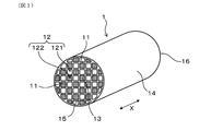
- FIG. 1 is a perspective view of the exhaust gas purification filter according to the first embodiment.
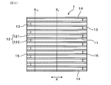
- FIG. 2 is a cross-sectional view taken along the filter axial direction of the exhaust gas purification filter according to the first embodiment.
- FIG. 3 is a diagram showing the flow of exhaust gas in the exhaust gas purification filter according to the first embodiment.
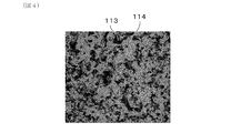
- FIG. 4 is a diagram showing an example of a reflected electron image of the partition wall surface obtained by a scanning electron microscope obtained when measuring the surface opening diameter of pores on the partition wall surface in the exhaust gas purification filter according to the first embodiment.
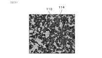
- FIG. 5 is a diagram showing an example of a binarized image obtained by binarizing the reflected electron image of FIG. 4.
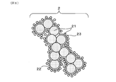
- FIG. 6 is a diagram schematically showing the microstructure of PM.
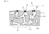
- FIG. 7 is an enlarged cross-sectional view of the partition wall on which the surface side of the partition wall into which the exhaust gas flows is shown.
- FIG. 8 is a diagram showing how PM is segregated in the vicinity of the surface opening in the partition wall shown in FIG. 7.
- FIG. 9 is a diagram showing how the ash contained in the PM remains after the PM shown in FIG. 8 is regenerated.
- FIG. 10 is a diagram showing how PM is collected again in the state where the residual ash content shown in FIG. 9 is present.
- FIG. 10 is a diagram showing how PM is collected again in the state where the residual ash content shown in FIG. 9 is present.
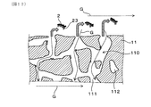
- FIG. 11 is a diagram showing a state in which ash crosslinks the surface openings of the pores on the partition wall surface by repeating the PM deposition and the PM regeneration process from the state of FIG.
- FIG. 12 is a diagram showing how the ash that crosslinks the surface opening shown in FIG. 11 is peeled off by the flow of exhaust gas, and the peeled ash is transported to the sealing portion on the gas outflow side.
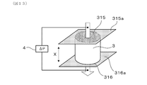
- FIG. 13 is a diagram showing a method of measuring the gas permeability coefficient of the exhaust gas purification filter.
- FIG. 14 (a) is a diagram showing an example of a tape for forming a sealing portion attached to the upstream end face of the measurement sample collected from the exhaust gas purification filter, and FIG.
- FIG. 14 (b) is a diagram showing an example of the tape for forming a sealing portion, and FIG. 14 (b) is from the exhaust gas purification filter. It is a figure which showed an example of the tape for forming a sealing part attached to the downstream end face of the collected measurement sample.
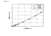
- FIG. 15 is a diagram showing an example of a relationship diagram between the gas flow velocity (X-axis) and the pressure loss (Y-axis).
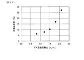
- FIG. 16 is a diagram showing the relationship between the gas permeability coefficient ratio k c / k 10 and the pressure drop increase rate obtained in the experimental example.
- the exhaust gas purification filter 1 of the present embodiment is used by being arranged in an exhaust passage (not shown) of a gasoline engine. That is, the exhaust gas purification filter 1 is a gasoline particulate filter (GPF) capable of collecting PM2 (see FIG. 6 described later) discharged from the gasoline engine.
- GPF gasoline particulate filter
- the direction of the arrows on both ends shown in FIGS. 1 to 3 is defined as the filter axial direction X of the exhaust gas purification filter 1.
- the exhaust gas purification filter 1 has a partition wall 11, a plurality of cells 12, and a sealing portion 13. As illustrated in FIGS. 1 and 2, the partition wall 11 has, for example, a grid-like shape in a cross-sectional view perpendicular to the filter axial direction X inside the skin portion 14 formed in a cylindrical shape such as a cylinder. Can be provided to exhibit.
- the partition wall 11 and the skin portion 14 can be formed of, for example, cordierite or the like.
- the sealing portion 13 can be formed of, for example, ceramics such as cordierite, but may be made of other materials.
- the plurality of cells 12 are formed by being partitioned by a partition wall 11.
- the cell 12 is surrounded by the partition wall 11 to form a gas flow path.
- the extension direction of the cell 12 usually coincides with the filter axial direction X.
- the cell shape can be, for example, a quadrangular shape as illustrated in FIG.
- the cell shape is not limited to this, and may be, for example, a polygonal shape such as a triangular shape or a hexagonal shape, or a circular shape. Further, the cell shape may be composed of a combination of two or more different shapes.
- the plurality of cells 12 are alternately sealed by sealing portions 13 at both ends of the filter. Specifically, the plurality of cells 12 are first opened to the filter end face 15 (upstream end face) on the exhaust gas inflow side and closed by the sealing portion 13 on the filter end face 16 (downstream end face) on the exhaust gas outflow side. It can have a cell 121 and a second cell 122 which is open to the filter end face 16 on the exhaust gas outflow side and is closed by the sealing portion 13 on the filter end face 15 on the exhaust gas inflow side. As a result, as illustrated in FIG.
- the exhaust gas G that has flowed into the first cell 121 from the filter end surface 15 on the exhaust gas inflow side flows through the first cell 121 and also through the porous partition wall 11. It reaches 2 cells 122.
- the exhaust gas G that has reached the second cell 122 flows in the second cell 122 and is discharged from the filter end surface 16 on the exhaust gas outflow side.
- the first cell 121 and the second cell 122 are alternately arranged so as to be adjacent to each other, for example, in the horizontal direction orthogonal to the filter axial direction X and in the vertical direction orthogonal to both the filter axial direction X and the horizontal direction. It can be formed side by side. In this case, when the filter end face 15 on the exhaust gas inflow side or the filter end face 16 on the exhaust gas outflow side is viewed from the filter axial direction X, the first cell 121 and the second cell 122 are arranged in a check pattern, for example.
- the first cell 121 and the second cell 122 adjacent to each other are separated by a partition wall 11 in between.
- the partition wall 11 has a large number of pores 110 as illustrated in FIG. Specifically, the pore 110 in the partition wall 11 includes a communication hole 111 that communicates between the first cell 121 and the second cell 122 that are adjacent to each other. In addition to the communication holes 111, the pores 110 in the partition wall 11 may include non-communication holes 112 that do not communicate between the first cell 121 and the second cell 122 that are adjacent to each other.
- the average pore diameter of the partition wall 11 (that is, the average pore diameter inside the partition wall 11) is A ⁇ m
- the average pore diameter A is in the range of 5 ⁇ m or more and less than 15 ⁇ m.
- the average pore diameter A of the partition wall 11 is measured by a mercury porosimeter using the principle of the mercury intrusion method. Specifically, a test piece is cut out from the exhaust gas purification filter 1. However, the portion where the sealing portion 13 exists is excluded. The test piece is a rectangular parallelepiped having dimensions in the direction orthogonal to the filter axial direction X of 15 mm in length ⁇ 15 mm in width and a length of 20 mm in the filter axial direction X. Next, the test piece is stored in the measurement cell of the mercury porosimeter, and the pressure inside the measurement cell is reduced.
- the measurement is performed in the pressure range of 0.5 to 20000 psia.
- 0.5 psia corresponds to 0.35 ⁇ 10 -3 kg / mm 2
- 20000 psia corresponds to 14 kg / mm 2 .
- the range of the pore diameter corresponding to this pressure range is 0.01 to 420 ⁇ m.
- a contact angle of 140 ° and a surface tension of 480 dyn / cm are used.
- the average pore diameter A is a pore diameter (pore diameter at an integrated value of 50% of the pore volume) d 50 at which the cumulative pore volume is 50% in the pore diameter distribution of the partition wall 11.
- the average surface opening diameter of the pores 110 on the surface of the partition wall 11 is set to B ⁇ m.
- the ratio calculated by the formula of 100 ⁇ (AB) / B represented by the above-mentioned average pore diameter A and average surface opening diameter B is 30% or less.
- the average surface opening diameter B of the pores 110 on the surface of the partition wall 11 is measured as follows.
- a surface opening 113 is formed by pores 110 on the surface of the partition wall 11 on the side where the exhaust gas G flows in and the surface of the partition wall 11 on the side where the exhaust gas G flows out.
- a scanning electron microscope SEM
- the acceleration voltage can be 10 kV and the magnification can be 300 times.
- FIG. 4 shows an example of a reflected electron image on the surface of the partition wall 11. In the reflected electron image of FIG.
- the black region is the surface opening 113 on the surface of the partition wall 11
- the light gray region is the skeleton portion 114 on the surface of the partition wall 11.
- the binarization treatment aims to distinguish between the surface opening 113 on the surface of the partition wall 11 and the skeleton portion 114 on the surface of the partition wall 11. Since the surface opening 113 and the skeleton portion 114 have different brightnesses from each other, in the binarization process, noise remaining in the captured image is removed, and after setting an arbitrary threshold value, the binarization process is performed.
- FIG. 5 shows an example of a binarized image.
- the light gray region is the surface opening 113 on the surface of the partition wall 11
- the black region is the skeleton portion 114 on the surface of the partition wall 11.
- the equivalent circle diameter which is the diameter of a perfect circle having the same area as the surface opening 113, was calculated for each surface opening 113, and all the calculated circle equivalents were calculated.
- the value obtained by integrating the diameters and dividing by the number of surface openings 113 is taken as the surface opening diameter.
- the average value of each surface opening diameter obtained from each binarized image obtained for any five different locations on the partition wall 11 surface as described above is defined as the average surface opening diameter B of the pores 110 on the partition wall 11 surface. ..
- the value of the average pore diameter A of the partition wall 11 defined as described above is equal to or greater than the average surface opening diameter B of the pores 110 on the surface of the partition wall 11 (A ⁇ B). Further, the exhaust gas purification filter 1 has 100 ⁇ (A ⁇ ) represented by the value of the average pore diameter A of the partition wall 11, the average pore diameter A of the partition wall 11, and the average surface opening diameter B of the pores 110 on the surface of the partition wall 11.
- the ratios calculated by the formulas B) / B are within the specific ranges described above.
- PM2 contains solid carbon (suit) 21, which is the main component, as well as soluble organic component (SOF) 22, and ash (Ash) 23 derived from engine oil and the like.
- suitable solid carbon
- SOF soluble organic component
- Ash ash
- PM2 is collected as it passes through the pores 110 in the partition wall 11.
- the arrow in FIG. 7 indicates the flow of the exhaust gas G flowing in the pore 110.
- the surface opening 113 on the surface of the partition wall 11 is crosslinked by the ash 23 by repeating the deposition of PM2 containing the ash 23 and the regeneration process of PM2.
- the ash 23 that had crosslinked the surface opening 113 was peeled off during the regeneration of PM2 or the flow of the exhaust gas G, and the peeled ash 23 was the sealing portion 13 on the gas outflow side.
- the transported ash 23 is deposited on the most downstream portion 10 of the filter (see FIG. 3, which can also be referred to as the bottom portion of the filter).
- the ash 23 covering the outer surface of the partition wall 11 increases the pressure loss, but the ash 23 deposited on the most downstream portion 10 of the filter does not easily increase the pressure loss.
- the ash content 23 is crosslinked at the surface opening 113 of the partition wall 11, and the ash content 23 is likely to be peeled off. As a result, it is possible to increase the amount of ash 23 deposited on the most downstream portion 10 of the filter rather than the ash 23 covering the outer surface of the partition wall 11.
- the above mechanism makes it possible not only to secure the initial PM collection rate of the exhaust gas purification filter 1 and to reduce the initial pressure loss, but also to suppress the increase in pressure loss after the ash 23 is deposited.
- the average pore diameter A of the partition wall 11 when the average pore diameter A of the partition wall 11 is less than 5 ⁇ m, the initial pressure drop reduction effect is diminished, and the pressure loss after the ash 23 is deposited tends to increase.
- the average pore diameter A of the partition wall 11 is 15 ⁇ m or more, the initial PM collection performance is lowered, and the pressure loss after the ash 23 is deposited tends to increase.
- the ratio calculated by the formula of 100 ⁇ (AB) / B exceeds 30%, the difference between the average pore diameter A and the average surface opening diameter B becomes large, and the ash content 23 is reduced.
- the PM2 contained therein is likely to be deposited inside the partition wall 11, and the ash 23 is difficult to be peeled off, resulting in an increase in pressure loss due to the ash 23 remaining accumulated due to the aged use of the vehicle.
- the exhaust gas purification filter 1 satisfies A ⁇ B as described above, the surface opening diameter of the pores 110 on the surface of the partition wall 11 is smaller than the pore diameter inside the partition wall 11, and 100 ⁇ ( The ratio calculated by the formula AB) / B is 0% or more.
- the surface opening ratio of the pores 110 on the surface of the partition wall 11 on the side where the exhaust gas G flows in can be 25% or more and 40% or less.
- the surface opening ratio of the pores 110 on the surface of the partition wall 11 By setting the surface opening ratio of the pores 110 on the surface of the partition wall 11 to 25% or more, the number of surface openings serving as the inlet of the exhaust gas G into the partition wall 11 increases, and the flow velocity of the exhaust gas G becomes slow, so that the initial pressure loss is reduced. It becomes easier to obtain the effect.
- PM2 containing the ash content 23 is less likely to be deposited inside the partition wall 11, and it is easy to suppress an increase in pressure loss after the ash content 23 is deposited.
- the surface aperture ratio of the pores 110 on the surface of the partition wall 11 is an expression of 100 ⁇ (total value of the area of each surface opening 113 in all the above-mentioned binarized images) / (total value of the area of all the binarized images). Can be calculated from. All binarized images mean the above-mentioned five binarized images.
- the porosity of the partition wall 11 can be 50% or more and 70% or less.
- the porosity of the partition wall 11 can be preferably 52% or more, more preferably 60% or more, from the viewpoint of reducing initial pressure loss and the like.
- the porosity of the partition wall 11 can be preferably 68% or less, more preferably 67% or less, still more preferably 66% or less, from the viewpoint of improving the strength of the exhaust gas purification filter 1.
- the upper and lower limits can be arbitrarily combined.
- the pore diameter at which the cumulative pore volume in the pore diameter distribution of the partition wall 11 by the mercury porosimeter using the principle of the mercury injection method described above is 75% (pore diameter at an integrated value of 75% of the pore volume) d 75.
- the exhaust gas purification filter 1 shall satisfy XY ⁇ 7 ⁇ m, where X ⁇ m and the pore diameter (pore diameter at the integrated value of 25% of the pore volume) d 25 where the cumulative pore volume is 25% are Y ⁇ m. Can be done. According to this configuration, the flow velocity of the exhaust gas G tends to be uniform, and it is possible to ensure the suppression of the increase in pressure loss after the accumulation of ash.
- XY can be preferably 6.8 ⁇ m or less, more preferably 6.5 ⁇ m or less, from the viewpoint of suppressing an increase in pressure loss after ash accumulation. From the viewpoint of cost and the like, XY can be preferably 3.5 ⁇ m or more, more preferably 5.0 ⁇ m or more.
- the exhaust gas purification filter 1 sets the gas permeability coefficient of the partition wall 11 at the position X 10 (see FIG. 2) 10 mm from the filter end face 15 on the exhaust gas inflow side in a state where the ash 23 of 20 g / L or more and 40 g / L or less is deposited.
- the gas permeability coefficient of the partition wall at the center position X C (see FIG. 2) between the filter end face 16 of the filter end face 15 and the exhaust gas outflow side of the exhaust gas inlet side was set to k c
- the value of k 10 can be 1.5 or less. According to this configuration, it is possible to ensure the suppression of the increase in pressure loss after ash accumulation.
- the accumulated amount of ash 23 is set to 20 g / L or more.
- the accumulated amount of the ash 23 is set to 40 g / L or less.
- k c / k 10 is an index showing the magnitude relationship between the gas permeability coefficient k c and the gas permeability coefficient k 10 .
- the gas permeability coefficient of the partition wall 11 decreases as the ash content 23 accumulates.
- the flow velocity of the exhaust gas G introduced into the cell 12 of the exhaust gas purification filter 1 is such that the filter end face 15 on the exhaust gas inflow side and the filter on the exhaust gas outflow side are located at the position X10 10 mm from the filter end face 15 on the exhaust gas inflow side. faster than the center position X C between the end face 16.
- the amount of ash 23 deposited at the position X 10 10 mm from the filter end face 15 on the exhaust gas inflow side is larger than that at the central position X C between the filter end face 15 on the exhaust gas inflow side and the filter end face 16 on the exhaust gas outflow side.
- the relationship between the gas permeability coefficient k 10 and the gas permeability coefficient k c after the ash 23 is deposited is larger in the gas permeability coefficient k c than in the gas permeability coefficient k 10 . That is, in the conventional exhaust gas purification filter not provided with the configuration of the present disclosure, the value of k c / k 10 is usually large.
- the value of k c / k 10 exceeds 1.5, the rate of increase in pressure drop after the accumulation of ash 23 with respect to the initial pressure drop becomes high, which is not preferable. It is considered that this is because the ash 23 on the surface of the partition wall 11 at the position X 10 10 mm from the filter end surface 15 on the exhaust gas inflow side is not peeled off and is deposited in the pores 110. Therefore, in order to suppress the pressure drop increase rate, the value of k c / k 10 is preferably 1.5 or less.
- the gas permeability coefficients k 10 and k c are measured as follows. First, an ash content 23 of 20 g / L or more and 40 g / L or less is deposited on the exhaust gas purification filter 1.
- the ash 23 can be deposited by operating a gasoline engine using gasoline containing 2% of ash derived from engine oil and depositing the ash on the exhaust gas purification filter 1 mounted on the exhaust passage. Specifically, (1) PM2 is deposited under the condition of (1) a stoichiometric atmosphere and the center temperature of the exhaust gas purification filter 1 at 800 ° C. for 9 minutes, and (2) the center temperature of the exhaust gas purification filter 1 is 800 ° C. PM2 is regenerated at ⁇ 900 ° C. for 1 minute.
- the ash content 23 is deposited on the exhaust gas purification filter 1.
- the accumulated amount of the ash content 23 can be grasped by appropriately taking out the exhaust gas purification filter 1 and measuring the weight.
- each measurement sample is a cylindrical shape having a diameter of 30 mm and a length of 25 mm in the filter axial direction.
- the skin portion 14 of each hollowed-out measurement sample can be formed by, for example, cementing.
- polyester tapes 315a and 316a are attached to both end faces 315 and 316 of the measurement sample 3 in the filter axial direction X, respectively.
- the polyester tapes 315a and 316a are partially eliminated by, for example, a soldering iron so that the alternating sealing portions 13 are formed by the polyester tapes 315a and 316a.
- 13 cells 12 are opened and the remaining cells 12 are opened as illustrated in FIG. 14A. It is closed by a sealing portion 13 made of polyester tape 315a.
- the downstream end surface 316 which is the exhaust gas outflow side filter end surface in the measurement sample 3
- 24 cells 12 are opened and the remaining cells 12 are made of polyester tape 316a as illustrated in FIG. 14 (b).
- the sealing portion 13 is closed. That is, instead of the sealing portion 13 made of ceramics, the sealing portion 13 made of polyester tapes 315a and 316a is formed.
- the measurement sample 3 in which the sealing portion 13 is formed by the polyester tapes 315a and 316a has been described here, but the measurement sample 3 in which the sealing portion 13 made of ceramics is formed may also be used. Similar results are obtained.
- gas is flowed from the upstream end surface 315 of the measurement sample 3 toward the downstream end surface 316 of the measurement sample 3, and the relationship between the gas flow velocity and the pressure loss is measured by the palm pollometer 4.
- the pressure loss when the gas flow velocity is changed is measured.
- the arrow in FIG. 13 indicates the gas flow.
- the relationship diagram between the gas flow velocity (X-axis) and the pressure loss (Y-axis) is obtained.
- FIG. 15 shows an example of a relationship diagram between the gas flow velocity (X-axis) and the pressure loss (Y-axis).
- the measured value (plot point) by the palm pollometer 4 and the calculated value (broken line) obtained by the following equations (i) to (viii) are shown.
- the equations (i) to (viii) will be described below.
- ⁇ P inlet / exit the opening area A open (unit: m 2 ) of the cell 12
- the opening area A in (unit: m 2 ) of the cell 12 at the filter end face 15 on the exhaust gas inflow side and the gas flow velocity in the cell 12.
- the V channel (unit: m / s) and the air density ⁇ (unit: kg / m 3 ) satisfy the relationship of the following equation (ii).
- ⁇ P channel + ⁇ P wall a gas permeation coefficient k (unit: m 2 ), a length L (unit: m) of the filter axial direction X of the exhaust gas purification filter 1, and a hydraulic diameter a 1 (unit: m) of the cell 12.
- m) the thickness w (unit: m) of the partition wall 11, the friction coefficient F (unit: dimensionless) in the cell 12, the Reynolds number (unit: dimensionless), and the gas viscosity ⁇ (unit: Pa ⁇ s).
- the gas flow velocity V channel (unit: m / s) in the cell 12 satisfy the relationship of the following equations (iii) to (viii).
- equation (iii) e is an exponential function exp.
- the pressure drop value is calculated based on the above formulas (i) to (viii).
- the dashed line based on the calculated value shown in the relationship diagram between the gas flow velocity (X-axis) and the pressure loss (Y-axis) illustrated in FIG. 15 is the pressure loss value obtained by calculation.
- the pressure drop value measures the filter length L, the cell opening area A open , the hydraulic diameter a 1 , and the thickness w of the partition wall 11, excluding the gas permeability coefficient k. These values do not change even if the gas flow velocity is changed. Therefore, by inputting an arbitrary value to the gas permeability coefficient, the calculated value in the relationship diagram between the gas flow velocity (X-axis) and the pressure loss (Y-axis) can be derived.
- the gas permeability coefficient k is a value obtained by back-calculating the gas permeability coefficient from the measured values of the pressure loss measured by the palm polo meter from the equations (i) to (viii). As described above, the gas permeability coefficients k 10 and k c at a predetermined position in a state where a predetermined amount of ash is deposited can be obtained.
- the exhaust gas purification filter 1 described above can exert a sufficient effect when used in a state where the catalyst is not supported on the partition wall 11.
- Example 1 -Manufacturing of exhaust gas purification filter- (Example 1)
- porous silica (Si source), talc (Mg source), and aluminum hydroxide (Al source) are blended so as to have the blending ratio (mass%) shown in Table 1.
- a raw material for forming talc was prepared.
- the bulk density of the porous silica used is 0.18 g / cm 3 .
- a tap densor manufactured by Seishin Enterprise Co., Ltd. which is a tap density method fluidity adhesive force measuring instrument, was used. Specifically, after filling the cylinder of the measuring instrument with silica, the silica was compressed by tapping, and the bulk density was calculated from the mass of the compressed silica and the volume of the cylinder. Further, as the aluminum hydroxide, one having an average particle diameter of 3 ⁇ m and one having an average particle diameter of 8 ⁇ m were used.
- the "average particle size” refers to the particle size when the volume integrated value in the particle size distribution obtained by the laser diffraction / scattering method is 50%.
- solvent Water (solvent), methyl cellulose (binder), and a dispersant are added to the cordierite forming raw material so as to have the blending ratio (mass%) shown in Table 1, and the mixture is mixed by a kneader to form the cordierite forming raw material.
- a solvent containing the above was prepared.
- the dispersant mainly suppresses agglomeration of particles and improves solvability.
- polyoxyethylene polyoxypropylene glyceryl ether having an average molecular weight of 4550 was used.
- the soil density deviation rate was introduced as a new index of particle dispersibility in the kneaded soil.
- the clay before extrusion molding is taken out with a mold, and the clay at eight places is randomly taken out.
- the extracted clay was put into a measuring instrument with a diameter of 25 mm and a length of 20 mm in the pressure measuring instrument "Autograph" manufactured by Shimadzu Corporation, and the volume of the earth and the soil taken out by compressing with a pressurization of 1 kN. Calculate the clay density from the weight.
- the average value of the soil density calculated for the eight soils is taken as the measured soil density.
- the clay density calculated in advance from the mixing ratio of the raw materials is defined as the calculated clay density.
- the particle dispersibility it is possible to judge the particle dispersibility by confirming the difference (deviation rate) of the soil density measured with respect to the soil density calculated by this calculation. As the measured soil density becomes smaller than the calculated soil density, the wettability of the dispersant is poor and more air is present on the particle surface, resulting in poor particle dispersibility. On the other hand, the closer the measured soil density is to the calculated value of the soil density, the better the particle dispersibility.
- Example 1 the speed of the kneader and the number of times the kneading machine was repeatedly passed through the kneading machine were arbitrarily changed to use the kneading soil adjusted so that the following kneading density deviation rate was less than 10%.
- the soil density deviation rate tends to decrease.
- the clay prepared as described above was formed into a honeycomb shape by extrusion molding.
- the molded product was cut to a predetermined length after drying.
- the molded product was fired at 1430 ° C. to obtain a sintered body having a honeycomb structure.
- the exhaust gas inflow end face and the exhaust gas outflow end face of the cell were alternately filled and fired with a slurry containing a ceramic raw material of the same type as the sintered body having a honeycomb structure to form a sealed portion.
- Example 2 In Example 1, the average particle size and bulk density of the porous silica in the cordierite forming raw material were changed. The larger the average particle size of the porous silica, the larger the porosity of the formed partition wall, and the smaller the bulk density of the porous silica, the higher the porosity of the formed partition wall. Further, when the proportion of the particle size is increased in the compounding of aluminum hydroxide having different particle size, the surface aperture ratio and the average surface opening diameter become large. Further, by increasing the rate of temperature rise between 1200 ° C. and 1430 ° C. during firing, the pore diameter and the average surface opening diameter can be increased. It was prepared by combining these conditions.
- the total blending ratio of aluminum hydroxide was the same as that of Example 1, the blending of aluminum hydroxide having different particle sizes was changed, and the blending ratio of other clay was the same as that of Example 1. Then, in the same manner as in Example 1, the speed of the kneader and the number of times the clay is repeatedly passed through the kneader are arbitrarily changed to use the clay adjusted so that the clay density deviation rate is less than 10%.
- the exhaust gas purification filters of Examples 2 to 8 were produced by changing the heating rate between 1200 ° C. and 1430 ° C. during firing.
- Example 9 In Example 1, the average particle size and bulk density of the porous silica in the cordierite forming raw material are changed, and the speed of the kneader and the number of times the clay is repeatedly passed through the kneader are arbitrarily changed to dissociate the clay density.
- the exhaust gas purification filter of Example 9 was produced by using silica soil adjusted so that the rate was 10% or more.
- the bulk density of the porous silica used is 0.25 g / cm 3 .
- Example 10 Example 9
- Example 9 the average particle size and bulk density of the porous silica in the cordierite forming raw material were changed.
- the exhaust gas purification filters of Examples 10 and 11 were produced by adjusting the soil so that the soil density deviation rate was 10% or more in the same manner as in Example 9.
- Comparative Example 1 In producing the exhaust gas purification filter of Comparative Example 1, fused silica (Si source), talc (Mg source), and aluminum hydroxide (Al source) are blended so as to have the blending ratio (mass%) shown in Table 2. To prepare a raw material for forming talc. The bulk density of the molten silica used is 1.30 g / cm 3 .
- lubricating oil Water (solvent), methyl cellulose (binder), lubricating oil, and graphite are added to the cordierite forming raw material so as to have the blending ratios shown in Table 2, and mixed by a kneader to contain the cordierite forming raw material.
- Graphite was prepared.
- the purpose of the lubricating oil is to improve the slippage of the clay, the molding machine and the metal part on the surface of the mold to increase the molding speed.
- rapeseed oil which is a vegetable oil
- the clay density deviation rate was adjusted to be less than 10% by arbitrarily changing the speed of the kneader and the number of times the clay was repeatedly passed through the kneader.
- the exhaust gas purification filter of Comparative Example 1 was produced in the same manner as in Example 1 thereafter.
- Comparative Example 2 Comparative Example 3
- Comparative Example 3 the average particle size of molten silica and talc and the blending ratio of graphite in the cordierite forming raw material were changed.
- the exhaust gas purification filters of Comparative Example 2 and Comparative Example 3 were produced by adjusting the soil so that the soil density deviation rate was less than 10% in the same manner as in Comparative Example 1.
- Comparative Example 4 In producing the exhaust gas purification filter of Comparative Example 4, porous silica (Si source), talc (Mg source), and aluminum hydroxide (Al source) are blended so as to have the blending ratio (mass%) shown in Table 3. As a result, a raw material for forming talc was prepared. The bulk density of the porous silica used is 0.25 g / cm 3 .
- Water (solvent), methylcellulose (binder), and lubricating oil are added to the cordierite-forming raw material so as to have the blending ratios shown in Table 3, and the clay is mixed with a kneader to contain the cordierite-forming raw material.
- the lubricating oil rapeseed oil, which is the same vegetable oil as above, was used.
- the soil density deviation rate was adjusted to be 10% or more by arbitrarily changing the speed of the kneader and the number of times the soil was repeatedly passed through the kneader.
- the exhaust gas purification filter of Comparative Example 4 was produced in the same manner as in Example 1 thereafter.
- Comparative Example 5 Comparative Example 6
- Comparative Example 4 the average particle size and bulk density of the porous silica in the cordierite forming raw material were changed.
- the exhaust gas purification filters of Comparative Example 5 and Comparative Example 6 were produced by adjusting the soil so that the soil density deviation rate was 10% or more in the same manner as in Comparative Example 4.
- partition wall characteristics of the exhaust gas purification filters of Examples and Comparative Examples were measured. Specifically, according to the measurement method described above, the average pore diameter A of the partition wall, XY (pore diameter d 75 -pore diameter d 25 ) in the pore diameter distribution of the partition wall, and the porosity of the partition wall were measured. At this time, an Autopore IV9500 manufactured by Shimadzu Corporation was used as the mercury porosimeter. Further, according to the measurement method described above, the average surface opening diameter B of the pores on the partition wall surface and the surface opening ratio of the pores on the partition wall surface were measured. At this time, Quanta250FEG manufactured by FEI was used as the SEM.
- the image analysis software includes WinROOF Ver. From Mitani Corporation. 7.4 was used. Further, the ratio calculated by the formula of 100 ⁇ (AB) / B was calculated from the average pore diameter A of the obtained partition wall and the average surface opening diameter B of the pores on the partition wall surface. Further, the value of the gas permeability coefficient ratio k c / k 10 was measured according to the above-mentioned measuring method. At this time, CEP-1100AXSHJ manufactured by Porous Materials was used as the palm porometer.
- the initial PM collection rate, initial pressure loss, and pressure loss after ash accumulation were measured.
- the initial PM collection rate, initial pressure drop, and pressure loss after ash accumulation are ⁇ 118.4 mm (filter diameter) x L120 mm (filter length), the bulkhead thickness is 8.5 mil, and the number of cells is 300 cpsi.
- An exhaust gas purification filter having a certain cell structure was used.
- the initial PM collection rate was measured as follows.
- the produced exhaust gas purification filter was installed in the exhaust pipe of a gasoline direct injection engine, and exhaust gas containing PM was allowed to flow through the exhaust gas purification filter.
- N in which is the number of PMs in the exhaust gas before flowing into the exhaust gas purification filter
- N out which is the number of PMs in the exhaust gas flowing out from the exhaust gas purification filter
- the initial PM collection rate was calculated from the N in formula.
- the measurement conditions were a temperature of 450 ° C. and an exhaust gas flow rate of 2.8 m 3 / min.
- a PM particle number counter "AVL-489" manufactured by AVL was used for the measurement of the PM number.
- the initial pressure drop was measured as follows. At the same time as the measurement of the initial PM collection rate, the pressure before the exhaust gas purification filter (upstream) and the pressure after the exhaust gas purification filter (downstream) were measured by the pressure sensor, and the difference was taken as the initial pressure loss. At this time, the measurement conditions were a temperature of 720 ° C. and an exhaust gas flow rate of 11.0 m 3 / min. For each measurement, each exhaust gas purification filter in the initial state in which PM was not deposited and in which the catalyst was not coated was used.
- the case where the initial PM collection rate was 80% or more was designated as "A” because the initial PM collection rate was sufficiently secured.
- the case where the initial PM collection rate was 70% or more and less than 80% was designated as “B” as the initial PM collection rate was secured.
- the initial PM collection rate was less than 70% it was designated as “C” because the initial PM collection rate was not secured.
- the case where the initial pressure loss was 6 kPa or less was designated as “A” because the effect of reducing the initial pressure loss was sufficiently obtained.
- the initial pressure loss was more than 6 kPa and 7 kPa or less, it was designated as "B” because the effect of reducing the initial pressure drop was obtained.
- the initial pressure drop was more than 8 kPa it was designated as "C” because the effect of reducing the initial pressure drop was not obtained.
- Ash was deposited on the exhaust gas purification filter by repeating the PM regeneration process of regenerating the PM at 800 ° C. to 900 ° C. for 1 minute. At this time, the accumulated amount of ash was grasped by taking out an exhaust gas purification filter and measuring the weight as appropriate. After that, the pressure before the exhaust gas purification filter and the pressure after the exhaust gas purification filter were measured by the pressure sensor in the same manner as the above initial pressure loss, and the difference was taken as the pressure loss after the ash accumulation. In this experimental example, when the pressure loss after ash deposition when 30 g / L of ash is deposited is 11 kPa or less, it is considered that the effect of suppressing the increase in pressure loss after ash accumulation is sufficiently obtained. And said.
- FIG. 16 shows the relationship between the gas permeability coefficient ratio k c / k 10 and the pressure drop increase rate.
- FIG. 16 shows the result of the exhaust gas purification filter of Example 4 as a representative example of each Example.
- the ratio calculated by the formula of 100 ⁇ (AB) / B is 30% or less, and ash is contained by setting A ⁇ B. It can be seen that PM is less likely to be deposited inside the partition wall, and it becomes easier to suppress an increase in pressure loss due to the accumulated residual ash during aged use of the vehicle. Further, when the exhaust gas purification filters of Examples 1 to 8 and the exhaust gas purification filters of Examples 9 to 11 are compared, the initial PM collection rate is secured and the initial PM collection rate is secured by satisfying XY ⁇ 7 ⁇ m. It can be seen that the pressure loss reduction effect of
- the exhaust gas purification filters of Examples 1 to 11 have a gas permeability coefficient ratio of k c / k 10 of 1.5 or less in a state where ash content of 20 g / L or more and 40 g / L or less is deposited. According to this configuration, as shown in FIG. 16, it can be said that the suppression of the pressure drop increase after the ash accumulation can be ensured.
Abstract
排ガス浄化フィルタ(1)は、ガソリンエンジンの排気通路に配置されるものである。排ガス浄化フィルタ(1)は、多数の気孔(110)を有する隔壁(11)と、隔壁(11)により区画された複数のセル(12)と、フィルタ両端部において複数のセル(12)を交互に目封じする封止部(13)と、を有している。排ガス浄化フィルタ(1)は、隔壁(11)の平均気孔径をAμm、隔壁11表面における気孔(110)の平均表面開口径をBμmとしたとき、A≧Bを満たし、かつ、Aが5μm以上15μm未満であり、100×(A-B)/Bの式にて算出される割合が30%以下である。
Description
本出願は、2019年3月29日に出願された日本出願番号2019-068162号に基づくもので、ここにその記載内容を援用する。
本開示は、排ガス浄化フィルタに関する。
ガソリンエンジン、ディーゼルエンジン等の内燃機関から排出される排ガス中には、パティキュレートと呼ばれる粒子状物質(以下、適宜「PM」ということがある。)が含まれる。この排ガス中のPMを捕集して排ガスの浄化を行うため、内燃機関の排気通路には排ガス浄化フィルタが配置される。
この種の排ガス浄化フィルタとしては、例えば、特許文献1には、ディーゼルエンジンから排出されるPMを捕集するディーゼルパティキュレートフィルタ(以下、「DPF」ということがある。)が記載されている。同文献には、具体的には、PMの堆積増加に伴う圧力損失の上昇を抑制するため、複数のセルを形成する隔壁が気孔率45~70%の多孔質の基材からなり、基材の水銀圧入法により測定される平均細孔径を(A)μm、バブルポイント法により測定される平均細孔径を(B)μmとした場合に、{(A-B)/B}×100で表される平均細孔径差率が35%以下であり、平均細孔径(B)が15~30μmであり、かつ、バブルポイント法で測定される最大細孔径が150μm以下であるDPFが開示されている。
ガソリンエンジンから排出されるPM量は、ディーゼルエンジンから排出されるPM量に比べて圧倒的に少ない。しかしながら、PMの個数規制が導入されているため、ガソリンエンジンを有する車両(以下、「ガソリン車両」)にも、ガソリンエンジンから排出されるPMを捕集可能なガソリンパティキュレートフィルタ(以下、適宜「GPF」ということがある。)の搭載が必要となっている。
ガソリン車両におけるPMの個数規制は、年々厳しくなっていくことが予想される。将来の規制をクリアするためには、初期時におけるPM捕集率の向上がより重要となる。ところで、GPFでは、排ガスを浄化するための触媒がコートされる場合がある。触媒がコートされると隔壁の気孔が一部閉塞されるため、PM捕集率および圧力損失(以下、適宜「圧損」ということがある。)が悪化する。また、ガソリンエンジンでは排ガスの温度が高く流速も速いため、ディーゼルエンジンに比べて圧損が増加しやすい。そのため、GPFにおいて触媒による排ガスの浄化を実施しつつ、PM捕集率の向上および圧損の低減を図ることは難易度が高い。そこで、将来の規制をクリアするための手段として、PMの捕集と触媒による排ガスの浄化という2つの機能を分離し、触媒をコートしないGPFが採用される可能性が高まっている。もっとも、触媒がコートされない場合でも、PM捕集率の向上と圧損の低減とはトレードオフの関係があるため、PM捕集率を向上させようとすると圧損が増加するという問題は残っている。
上記に加え、PM中には、固体状炭素(スート)の他、エンジンオイル由来等の灰分(Ash)が含まれている。灰分は、PMの再生処理後も残る成分である。ガソリン車両では、経年使用によって堆積した残存灰分による圧損上昇を抑制することが重要となる。なお、DPFも経年使用によって残存灰分が堆積して圧損が上昇するものの、排ガス温度が低く、排気レイアウトにも余裕があるため、灰分堆積後の圧損上昇の抑制はこれまで問題とはならなかった。
本開示は、初期のPM捕集率の確保、初期の圧損低減、および、灰分堆積後の圧損上昇の抑制を図ることができる排ガス浄化フィルタを提供することを目的とする。
本開示の一態様は、ガソリンエンジンの排気通路に配置される排ガス浄化フィルタであって、
多数の気孔を有する隔壁と、
上記隔壁により区画された複数のセルと、
フィルタ両端部において複数の上記セルを交互に目封じする封止部と、を有しており、
上記隔壁の平均気孔径をAμm、上記隔壁表面における上記気孔の平均表面開口径をBμmとしたとき、
A≧Bを満たし、かつ、Aが5μm以上15μm未満であり、
100×(A-B)/Bの式にて算出される割合が30%以下である、排ガス浄化フィルタにある。
多数の気孔を有する隔壁と、
上記隔壁により区画された複数のセルと、
フィルタ両端部において複数の上記セルを交互に目封じする封止部と、を有しており、
上記隔壁の平均気孔径をAμm、上記隔壁表面における上記気孔の平均表面開口径をBμmとしたとき、
A≧Bを満たし、かつ、Aが5μm以上15μm未満であり、
100×(A-B)/Bの式にて算出される割合が30%以下である、排ガス浄化フィルタにある。
上記排ガス浄化フィルタは、上記特定の構成を有しており、特に、隔壁の平均気孔径をAμm、隔壁表面における気孔の平均表面開口径をBμmとしたとき、A≧Bを満たし、Aの値、および、100×(A-B)/Bの式にて算出される割合がそれぞれ特定の範囲とされている。そのため、上記排ガス浄化フィルタによれば、初期のPM捕集率の確保、初期の圧損低減、および、灰分堆積後の圧損上昇の抑制を図ることができる。
なお、請求の範囲に記載した括弧内の符号は、後述する実施形態に記載の具体的手段との対応関係を示すものであり、本開示の技術的範囲を限定するものではない。
本開示についての上記目的およびその他の目的、特徴や利点は、添付の図面を参照しながら下記の詳細な記述により、より明確になる。その図面は、
図1は、実施形態1に係る排ガス浄化フィルタの斜視図であり、
図2は、実施形態1に係る排ガス浄化フィルタのフィルタ軸方向に沿う断面図であり、
図3は、実施形態1に係る排ガス浄化フィルタにおける排ガスの流れを示した図であり、
図4は、実施形態1に係る排ガス浄化フィルタにおいて、隔壁表面における気孔の表面開口径を測定する際に取得される、走査型電子顕微鏡による隔壁表面の反射電子像の一例を示した図であり、
図5は、図4の反射電子像を二値化処理してなる二値化画像の一例を示した図であり、
図6は、PMの微構造を模式的に示した図であり、
図7は、排ガスが流入する隔壁表面側を拡大して示した隔壁の断面図であり、
図8は、図7に示した隔壁における表面開口付近にPMが偏析される様子を示した図であり、
図9は、図8に示したPMが再生処理された後に、PM中に含まれていた灰分が残存する様子を示した図であり、
図10は、図9に示した残存灰分がある状態において、再びPMが捕集される様子を示した図であり、
図11は、図10の状態からさらにPMの堆積およびPMの再生処理が繰り返されることにより、隔壁表面における気孔の表面開口を灰分が架橋した様子を示した図であり、
図12は、図11に示した表面開口を架橋する灰分が排ガスの流れによって剥離し、剥離した灰分がガス流出側の封止部へ輸送される様子を示した図であり、
図13は、排ガス浄化フィルタのガス透過係数の測定方法を示した図であり、
図14(a)は、排ガス浄化フィルタから採取した測定試料の上流側端面に貼り付けられる封止部形成用のテープの一例を示した図であり、図14(b)は、排ガス浄化フィルタから採取した測定試料の下流側端面に貼り付けられる封止部形成用のテープの一例を示した図であり、
図15は、ガス流速(X軸)と圧損(Y軸)との関係図の一例を示した図であり、
図16は、実験例にて得られた、ガス透過係数比kc/k10と圧損上昇率との関係を示した図である。
(実施形態1)
実施形態1に係る排ガス浄化フィルタについて、図1~図15を用いて説明する。図1~図3に例示されるように、本実施形態の排ガス浄化フィルタ1は、ガソリンエンジンの排気通路(不図示)に配置されて使用されるものである。つまり、排ガス浄化フィルタ1は、ガソリンエンジンから排出されるPM2(後述の図6参照)を捕集可能なガソリンパティキュレートフィルタ(GPF)である。なお、図1~図3に示される両端矢印の方向を排ガス浄化フィルタ1のフィルタ軸方向Xとする。
実施形態1に係る排ガス浄化フィルタについて、図1~図15を用いて説明する。図1~図3に例示されるように、本実施形態の排ガス浄化フィルタ1は、ガソリンエンジンの排気通路(不図示)に配置されて使用されるものである。つまり、排ガス浄化フィルタ1は、ガソリンエンジンから排出されるPM2(後述の図6参照)を捕集可能なガソリンパティキュレートフィルタ(GPF)である。なお、図1~図3に示される両端矢印の方向を排ガス浄化フィルタ1のフィルタ軸方向Xとする。
排ガス浄化フィルタ1は、隔壁11と、複数のセル12と、封止部13と、を有している。図1および図2に例示されるように、隔壁11は、例えば、円筒状等の筒状に形成されたスキン部14の内側に、フィルタ軸方向Xに垂直な断面視において格子状等の形状を呈するように設けられることができる。排ガス浄化フィルタ1において、隔壁11、スキン部14は、例えば、コーディエライト等から形成されることができる。また、封止部13は、例えば、コーディエライト等のセラミックスにより形成されることができるが、その他の材質であってもよい。
複数のセル12は、隔壁11により区画されて形成されている。セル12は、隔壁11に囲まれガス流路を形成している。セル12の伸長方向は、通常、フィルタ軸方向Xと一致している。フィルタ軸方向Xに垂直な断面視において、セル形状は、例えば、図1に例示されるように、四角形状とすることができる。セル形状は、これに限定されることなく、例えば、三角形状、六角形状等の多角形や円形状などであってもよい。また、セル形状は、2種以上の異なる形状の組み合わせより構成されていてもよい。
複数のセル12は、図2に例示されるように、フィルタ両端部において封止部13により交互に目封じされている。具体的には、複数のセル12は、排ガス流入側のフィルタ端面15(上流側端面)に開口し、排ガス流出側のフィルタ端面16(下流側端面)において封止部13により閉塞された第1セル121と、排ガス流出側のフィルタ端面16に開口し、排ガス流入側のフィルタ端面15において封止部13により閉塞された第2セル122と、を有することができる。これにより、図3に例示されるように、排ガス流入側のフィルタ端面15より第1セル121内に流入した排ガスGは、第1セル121内を流れるとともに多孔質の隔壁11内を流れて第2セル122に至る。第2セル122に至った排ガスGは、第2セル122内を流れ、排ガス流出側のフィルタ端面16より排出される。
第1セル121と第2セル122とは、フィルタ軸方向Xに直交する横方向においても、フィルタ軸方向Xおよび横方向の双方に直交する縦方向においても、例えば、互いに隣り合うように交互に並んで形成されることができる。この場合、フィルタ軸方向Xから排ガス流入側のフィルタ端面15または排ガス流出側のフィルタ端面16を見たとき、第1セル121と第2セル122とが、例えば、チェック模様状に配置される。互いに隣接する第1セル121および第2セル122は、隔壁11を間に挟んで隔てられている。
隔壁11は、図7に例示されるように、多数の気孔110を有している。隔壁11内の気孔110は、具体的には、互いに隣接する第1セル121、第2セル122間を連通させる連通孔111を含んでいる。隔壁11内の気孔110は、連通孔111以外にも、互いに隣接する第1セル121、第2セル122間を連通させない非連通孔112を含んでいてもよい。
排ガス浄化フィルタ1において、隔壁11の平均気孔径(つまり、隔壁11内部の平均気孔径)をAμmとしたとき、平均気孔径Aは、5μm以上15μm未満の範囲にある。
隔壁11の平均気孔径Aは、水銀圧入法の原理を用いた水銀ポロシメータにより測定される。具体的には、排ガス浄化フィルタ1から試験片を切り出す。但し、封止部13が存在する部分は除く。試験片は、フィルタ軸方向Xと直交方向の寸法が縦15mm×横15mmであり、フィルタ軸方向Xの長さが20mmである直方体とされる。次いで、水銀ポロシメータの測定セル内に試験片を収納し、測定セル内を減圧する。その後、測定セル内に水銀を導入して加圧し、加圧時の圧力と試験片における隔壁11の気孔110内に導入された水銀の体積より、気孔径と気孔容積とを測定する。測定は、圧力0.5~20000psiaの範囲で行う。なお、0.5psiaは、0.35×10⁻³kg/mm2に相当し、20000psiaは14kg/mm2に相当する。この圧力範囲に相当する気孔径の範囲は0.01~420μmである。圧力から気孔径を算出する際の常数としては、接触角140°および表面張力480dyn/cmを使用する。平均気孔径Aは、隔壁11の気孔径分布において、累積気孔容積が50%となる気孔径(気孔容積の積算値50%における気孔径)d50のことである。
排ガス浄化フィルタ1において、隔壁11表面における気孔110の平均表面開口径をBμmとする。排ガス浄化フィルタ1は、上述した平均気孔径Aと平均表面開口径Bとによって表される100×(A-B)/Bの式にて算出される割合が30%以下とされている。隔壁11表面における気孔110の平均表面開口径Bは、次のようにして測定される。
排ガスGが流入する側の隔壁11表面および排ガスGが流出する側の隔壁11表面には気孔110による表面開口113が形成されている。ここでは、走査型電子顕微鏡(SEM)を用い、排ガスGが流入する側の隔壁11表面(つまり、上述した第1セル121に面する隔壁11表面)の反射電子像を取得する。但し、封止部13が存在する部分の隔壁11表面は除く。この際、加速電圧は10kV、倍率は300倍とすることができる。図4に、隔壁11表面の反射電子像の一例を示す。図4の反射電子像では、黒色領域が隔壁11表面の表面開口113であり、薄い灰色領域が隔壁11表面の骨格部114である。次いで、画像解析ソフト(WinROOF、三谷商事社製)を用い、撮影画像について二値化処理を行う。二値化処理は、隔壁11表面の表面開口113と隔壁11表面の骨格部114とを区別することを目的とする。表面開口113と骨格部114とは、相互に輝度が異なるため、二値化処理では、撮影画像に残るノイズの除去を施し、任意の閾値を設定した後に二値化処理を行う。撮影画像によって閾値は異なるため、撮影画像を目視にて確認しながら、表面開口113と骨格部114とを分離できる閾値を撮影画像ごとに設定する。図5に、二値化画像の一例を示す。図5の二値化画像では、薄い灰色領域が隔壁11表面の表面開口113であり、黒色領域が隔壁11表面の骨格部114である。得られた二値化画像における表面開口113について、表面開口113の面積と同じ面積を有する真円の直径である円相当径をそれぞれの表面開口113毎に算出し、算出された全ての円相当径を積算して、表面開口113の数で除した値を表面開口径とする。上記のようにして隔壁11表面の異なる任意の5か所について求めた各二値化画像から得られる各表面開口径の平均値が、隔壁11表面における気孔110の平均表面開口径Bとされる。
排ガス浄化フィルタ1は、上記のようにして規定される隔壁11の平均気孔径Aの値が隔壁11表面における気孔110の平均表面開口径B以上(A≧B)である。また、排ガス浄化フィルタ1は、隔壁11の平均気孔径Aの値、および、隔壁11の平均気孔径Aと隔壁11表面における気孔110の平均表面開口径Bとによって表される100×(A-B)/Bの式にて算出される割合が、それぞれ上述した特定の範囲とされている。これにより、排ガス浄化フィルタ1は、初期のPM捕集率の確保、初期の圧損低減、および、灰分堆積後の圧損上昇の抑制を図ることができる。以下、このような効果が得られるメカニズムを、図6~図12を用いて説明する。
図6に示されるように、PM2は、主成分である固体状炭素(スート)21の他、可溶有機成分(SOF)22やエンジンオイル由来等の灰分(Ash)23を含んでいる。図7に示されるように、PM2は、隔壁11内の気孔110を通過する際に捕集される。なお、図7中の矢印は、気孔110内を流れる排ガスGの流れを示したものである。隔壁11の平均気孔径をAμm、隔壁11表面の平均表面開口径をBμmとしたとき、A≧Bを満たし、Aの値、および、100×(A-B)/Bの式にて算出される割合がそれぞれ上述した特定の範囲とされている隔壁11に灰分23を含むPM2が捕集された場合、図8に示されるように、PM2は、排ガスGが流入する側の隔壁11表面に形成された表面開口113付近に偏析する。さらに、図9に示されるように、PM2が再生処理された後では、PM2中に含まれていた灰分23が残存する。図10に示されるように、残存する灰分23がある状態において、再び隔壁11に灰分23を含むPM2が捕集された場合、PM2は、隔壁11表面の表面開口113付近に偏析しつつ、残存する灰分23付近にも堆積する。図11に示されるように、灰分23を含むPM2の堆積およびPM2の再生処理が繰り返されることにより、隔壁11表面の表面開口113が灰分23によって架橋される。その後、図12に例示されるように、表面開口113を架橋していた灰分23が、PM2の再生時や排ガスGの流れによって剥離し、剥離した灰分23は、ガス流出側の封止部13へ輸送される。輸送された灰分23は、フィルタ最下流部10(図3参照、フィルタボトム部ということもできる)に堆積される。隔壁11外部の表面を覆う灰分23は、圧損を上昇させるが、フィルタ最下流部10に堆積した灰分23は、圧損を上昇させ難い。つまり、隔壁11の平均気孔径をAμm、隔壁11表面の平均表面開口径をBμmとしたとき、A≧Bを満たし、Aの値、および、100×(A-B)/Bの式にて算出される割合がそれぞれ上述した特定の範囲とされている隔壁11を採用することにより、隔壁11の表面開口113にて灰分23の架橋が生じ、上述した灰分23の剥離が生じやすくなる。その結果、隔壁11外部の表面を覆う灰分23よりもフィルタ最下流部10に堆積する灰分23を多くすることが可能になる。フィルタ最下流部10に堆積する灰分23が多くなれば、灰分23堆積後における隔壁11のガス透過性も高くなり、低圧損となる。以上のメカニズムにより、排ガス浄化フィルタ1の初期のPM捕集率の確保および初期の圧損低減の両立はもとより、灰分23堆積後の圧損上昇の抑制を図ることが可能になると考えられる。
排ガス浄化フィルタ1において、平均気孔径Aが平均表面開口径Bより小さくなると(A<B)、灰分23を含むPM2が隔壁11の気孔110内へと侵入しやすくなり、灰分23が気孔110内に堆積しやすくなる。そのため、表面開口113に架橋した灰分23の剥離が生じ難くなり、車両の経年使用によって堆積残存する灰分23による圧損上昇を抑制し難くなる。
排ガス浄化フィルタ1において、隔壁11の平均気孔径Aが5μm未満になると、初期の圧損低減効果が希薄となり、灰分23堆積後の圧損も上昇しやすくなる。一方、隔壁11の平均気孔径Aが15μm以上になると、初期のPM捕集性能が低下し、灰分23堆積後の圧損も上昇しやすくなる。
排ガス浄化フィルタ1において、100×(A-B)/Bの式にて算出される割合が30%超になると、平均気孔径Aと平均表面開口径Bとの差が大きくなり、灰分23を含むPM2が隔壁11内部に堆積しやすくなって灰分23が剥離し難くなり、車両の経年使用によって堆積残存する灰分23による圧損上昇を招く。なお、排ガス浄化フィルタ1は、上述のようにA≧Bを満たすため、隔壁11表面における気孔110の表面開口径の方が隔壁11の内部の気孔径よりも小さいということになり、100×(A-B)/Bの式にて算出される割合は0%以上となる。
排ガス浄化フィルタ1において、排ガスGが流入する側の隔壁11表面における気孔110の表面開口率は、25%以上40%以下とすることができる。隔壁11表面における気孔110の表面開口率を25%以上とすることにより、排ガスGの隔壁11内への入口となる表面開口数が多くなり、排ガスGの流速が遅くなるため、初期の圧損低減効果を得やすくなる。また、隔壁11表面における気孔110の表面開口率を40%以下とすることにより、灰分23を含むPM2が隔壁11内部に堆積し難くなり、灰分23堆積後の圧損上昇を抑制しやすくなる。
隔壁11表面における気孔110の表面開口率は、100×(上述した全ての二値化画像における各表面開口113の面積の合計値)/(全ての二値化画像の面積の合計値)の式より算出することができる。全ての二値化画像とは、上述した5か所の二値化画像という意味である。
排ガス浄化フィルタ1において、隔壁11の気孔率は、50%以上70%以下とすることができる。隔壁11の気孔率を50%以上とすることにより、排ガスGが隔壁11を通過する流路を確保しやすくなるため、初期の圧損低減を図りやすくなる。また、隔壁11の気孔率を70%以下とすることにより、排ガス浄化フィルタ1自体の強度を確保しやすくなり、ケーシング時の応力やPM2の再生処理時の発熱によるクラックを抑制しやすくなる。隔壁11の気孔率は、初期の圧損低減等の観点から、好ましくは、52%以上、より好ましくは、60%以上とすることができる。また、隔壁11の気孔率は、排ガス浄化フィルタ1の強度向上等の観点から、好ましくは、68%以下、より好ましくは、67%以下、さらに好ましくは、66%以下とすることができる。なお、これら上下限は、それぞれ任意に組み合わせることができる。
隔壁11の気孔率は、上述した水銀圧入法の原理を用いた水銀ポロシメータにより測定される。具体的には、隔壁11の気孔率は、次の関係式より算出することができる。
隔壁11の気孔率(%)=総気孔容積/(総気孔容積+1/隔壁材料の真比重)×100
なお、隔壁材料がコーディエライトの場合、コーディエライトの真比重としては2.52を用いることができる。
隔壁11の気孔率(%)=総気孔容積/(総気孔容積+1/隔壁材料の真比重)×100
なお、隔壁材料がコーディエライトの場合、コーディエライトの真比重としては2.52を用いることができる。
排ガス浄化フィルタ1において、上述した水銀圧入法の原理を用いた水銀ポロシメータによる隔壁11の気孔径分布における累積気孔容積が75%となる気孔径(気孔容積の積算値75%における気孔径)d75をXμm、累積気孔容積が25%となる気孔径(気孔容積の積算値25%における気孔径)d25をYμmとしたとき、排ガス浄化フィルタ1は、X-Y≦7μmを満たす構成とすることができる。この構成によれば、排ガスGの流速が均一となりやすく、灰分堆積後の圧損上昇の抑制を確実なものとすることができる。
X-Yは、灰分堆積後の圧損上昇の抑制等の観点から、好ましくは、6.8μm以下、より好ましくは、6.5μm以下とすることができる。X-Yは、コスト等の観点から、好ましくは、3.5μm以上、より好ましくは、5.0μm以上とすることができる。
排ガス浄化フィルタ1は、20g/L以上40g/L以下の灰分23が堆積した状態において、排ガス流入側のフィルタ端面15から10mmの位置X10(図2参照)における隔壁11のガス透過係数をk10、排ガス流入側のフィルタ端面15と排ガス流出側のフィルタ端面16との間の中央位置XC(図2参照)における隔壁のガス透過係数をkcとしたとき、ガス透過係数比kc/k10の値が1.5以下である構成とすることができる。この構成によれば、灰分堆積後の圧損上昇の抑制を確実なものとすることができる。
上記において、灰分23の堆積量が20g/Lより少なくなると、排ガス流入側のフィルタ端面15から10mmの位置X10、および、排ガス流入側のフィルタ端面15と排ガス流出側のフィルタ端面16との間の中央位置XCともに、隔壁11外部に灰分23が堆積されず、もしくは、微量であるため、灰分23の剥離による効果が分かり難い。そのため、上記において、灰分23の堆積量は20g/L以上とされる。一方、灰分23の堆積量が40g/Lより多くなると、剥離してフィルタ最下流部10に堆積した灰分23が多くなり、排ガス流入側のフィルタ端面15と排ガス流出側のフィルタ端面16との間の中央位置XCにまでその影響が及ぶことが考えられ、灰分23の剥離による効果が分かり難い。そのため、上記において、灰分23の堆積量は40g/L以下とされる。
kc/k10は、ガス透過係数kcとガス透過係数k10との大小関係を示す指標である。隔壁11のガス透過係数は、灰分23が堆積するほど値が小さくなる。また、排ガス浄化フィルタ1のセル12内に導入された排ガスGの流速は、排ガス流入側のフィルタ端面15から10mmの位置X10の方が、排ガス流入側のフィルタ端面15と排ガス流出側のフィルタ端面16との間の中央位置XCよりも速い。すなわち、排ガス流入側のフィルタ端面15から10mmの位置X10の方が、排ガス流入側のフィルタ端面15と排ガス流出側のフィルタ端面16との間の中央位置XCよりも灰分23の堆積量が多い関係となる。これをガス透過係数に置き換えて考えると、灰分23堆積後のガス透過係数k10とガス透過係数kcの関係は、ガス透過係数k10よりもガス透過係数kcの方が大きくなる。つまり、本開示の構成を備えていない従来の排ガス浄化フィルタでは、kc/k10の値が大きくなるのが通常である。実験例にて後述するが、具体的には、kc/k10の値が1.5を超えると、初期圧損に対する灰分23堆積後の圧損上昇率が高くなり好ましくない。これは、排ガス流入側のフィルタ端面15から10mmの位置X10における隔壁11表面の灰分23が剥離されず、気孔110内に堆積するためであると考えられる。よって、圧損上昇率を抑制するためには、kc/k10の値が1.5以下であることが好ましい。これは、排ガス流入側のフィルタ端面15から10mmの位置X10周辺における隔壁11表面の灰分23の剥離が促進されるためであると考えられる。もっとも、全ての灰分23が、剥離してフィルタ最下流部10の封止部13付近に輸送され、堆積するわけではない。一部の灰分23は、隔壁11内や隔壁11表面付近に残存する。上記結果としてkc/k10の値が1.5以下の範囲では、初期圧損に対する灰分23堆積後の圧損上昇率を低く抑えることが可能になる。
なお、各ガス透過係数k10、kcは、次のようにして測定される。先ず、排ガス浄化フィルタ1に20g/L以上40g/L以下の灰分23を堆積させる。灰分23の堆積は、エンジンオイル由来の灰分を2%含むガソリンを用いてガソリンエンジンを動かし、排気通路に搭載された排ガス浄化フィルタ1へ灰分を堆積させることにより実施することができる。具体的には、(1)ストイキ雰囲気下、排ガス浄化フィルタ1の中心温度800℃にて9分間の条件にてPM2を堆積させ、(2)大気雰囲気下、排ガス浄化フィルタ1の中心温度800℃~900℃にて1分間の条件にてPM2を再生処理する。上記(1)によるPM2の堆積と、上記(2)によるPM2の再生処理とを繰り返すことにより、排ガス浄化フィルタ1に灰分23を堆積させる。灰分23の堆積量は、適宜、排ガス浄化フィルタ1を取り出して重量測定することにより把握することができる。
次いで、上記所定量の灰分23を堆積させた排ガス浄化フィルタ1について、排ガス流入側のフィルタ端面15から10mmの位置X10、および、排ガス流入側のフィルタ端面15と排ガス流出側のフィルタ端面16との間の中央位置XCから、封止部13を含まない測定試料をそれぞれくり抜き採取する。この際、位置X10における測定試料は、排ガス流入側のフィルタ端面15から10mmの位置が上流側端面となるように採取する。一方、中央位置XCにおける測定試料は、中央位置XCが上流側端面となるように採取する。各測定試料の形状は、直径30mm、フィルタ軸方向の長さ25mmの円柱形状とされる。なお、くり抜かれた各測定試料のスキン部14は、例えば、セメンティングにより形成することが可能である。
次いで、図13に例示されるように、測定試料3のフィルタ軸方向Xにおける両端面315、316にそれぞれポリエステルテープ315a、316aを貼り付ける。次いで、ポリエステルテープ315a、316aによって交互の封止部13が形成されるように、例えば、半田ごてなどによってポリエステルテープ315a、316aを部分的に消失させる。このようにして、測定試料3における排ガス流入側のフィルタ端面である上流側端面315では、図14(a)に例示されるように、例えば13個のセル12を開口させるとともに残りのセル12をポリエステルテープ315aよりなる封止部13によって閉塞させる。一方、測定試料3における排ガス流出側のフィルタ端面である下流側端面316では、図14(b)に例示されるように、例えば24個のセル12を開口させるとともに残りのセル12をポリエステルテープ316aよりなる封止部13によって閉塞させる。つまり、セラミックスからなる封止部13の代わりに、ポリエステルテープ315a、316aからなる封止部13を形成する。なお、ここでは、ガス透過係数の測定にあたり、ポリエステルテープ315a、316aによって封止部13を形成した測定試料3について説明したが、セラミックス製の封止部13を形成した測定試料3を用いても同様の結果が得られる。
次いで、図13に例示されるように、測定試料3の上流側端面315から測定試料3の下流側端面316に向けてガスを流し、パームポロメータ4により、ガス流速と圧損との関係を測定する。具体的には、ガス流速を変更した際の圧損を測定する。なお、図13における矢印はガスの流れを示す。そしてガス流速(X軸)と圧損(Y軸)との関係図を求める。図15に、ガス流速(X軸)と圧損(Y軸)との関係図の一例を示す。この関係図にはパームポロメータ4による実測値(プロット点)と、以下の式(i)~(viii)により求めた計算値(破線)が示される。以下、式(i)~(viii)について説明する。
排ガス浄化フィルタ1の圧損ΔP(単位:Pa)と、セル12にガスが流入する際の縮合圧損ΔPinletとセル12からガスが流出する際の拡大圧損ΔPexitとの和ΔPinlet/exit(単位:Pa)と、セル12内のガス通過における圧損ΔPchannel(単位:Pa)と、隔壁11のガス通過における圧損ΔPwall(単位:Pa)とは、下記の式(i)の関係を満たす。
ΔP=ΔPinlet/exit+ΔPchannel+ΔPwall ・・・(i)
ΔP=ΔPinlet/exit+ΔPchannel+ΔPwall ・・・(i)
また、ΔPinlet/exitと、セル12の開口面積Aopen(単位:m2)、排ガス流入側のフィルタ端面15におけるセル12の開口面積Ain(単位:m2)、セル12内のガス流速Vchannel(単位:m/s)、空気密度ρ(単位:kg/m3)とは、下記の式(ii)の関係を満たす。

また、ΔPchannel+ΔPwallと、ガス透過係数k(単位:m2)と、排ガス浄化フィルタ1のフィルタ軸方向Xの長さL(単位:m)と、セル12の水力直径a1(単位:m)と、隔壁11の厚みw(単位:m)と、セル12内の摩擦係数F(単位:無次元)と、レイノルズ数(単位:無次元)と、ガス粘度μ(単位:Pa・s)と、セル12内のガス流速Vchannel(単位:m/s)とは、下記の式(iii)~式(viii)の関係を満たす。なお、式(iii)において、eは指数関数expのことである。


上記式(i)~(viii)に基づいて、圧損値を算出する。図15に例示したガス流速(X軸)と圧損(Y軸)との関係図に示す計算値による破線は、計算によって求めた圧損値である。式(i)~(viii)より理解されるように、圧損値は、ガス透過係数kを除き、フィルタ長さL、セルの開口面積Aopen、水力直径a1、隔壁11の厚みwを測定することにより算出され、ガス流速を変更してもこれらの値は変わらない。したがって、ガス透過係数に任意の値を入力することにより、ガス流速(X軸)と圧損(Y軸)との関係図における計算値を導出することができる。
例えば、ガス透過係数の大きい値を入力すれば、実測値よりも圧損値が低くなり、計算値が実測値を下回る。一方、ガス透過係数の小さい値を入力すれば、計算値が実測値を上回る。そこで、計算値が実測値に最も近くなるように近似させるために、最小二乗法にて計算値と実測値の差が最小となるガス透過係数kを算出する。この算出値がガス透過係数kとなる。つまり、ガス透過係数kは、パームポロメータにて測定した圧損の実測値から、式(i)~(viii)よりガス透過係数を逆算した値である。以上のようにして、所定量の灰分が堆積した状態における所定位置でのガス透過係数k10、kcを求めることができる。
上述した排ガス浄化フィルタ1は、隔壁11に触媒が担持されていない状態にて使用されることによって十分な効果を発揮することができる。
<実験例>
実施例および比較例の各排ガス浄化フィルタについて説明する。本実験例では、各排ガス浄化フィルタは、SiO2:45質量%以上55質量%以下、Al2O3:33質量%以上42質量%以下、MgO:12質量%以上18質量%以下を含む化学組成を有するコーディエライトを主成分とする。なお、コーディエライトを主成分とするとは、50質量%以上がコーディエライトであることを意味する。したがって、本実験例における各排ガス浄化フィルタの作製にあたっては、焼成によってコーディエライトが生成するようにSi源、Al源およびMg源を含むコーディエライト形成原料が用いられる。
実施例および比較例の各排ガス浄化フィルタについて説明する。本実験例では、各排ガス浄化フィルタは、SiO2:45質量%以上55質量%以下、Al2O3:33質量%以上42質量%以下、MgO:12質量%以上18質量%以下を含む化学組成を有するコーディエライトを主成分とする。なお、コーディエライトを主成分とするとは、50質量%以上がコーディエライトであることを意味する。したがって、本実験例における各排ガス浄化フィルタの作製にあたっては、焼成によってコーディエライトが生成するようにSi源、Al源およびMg源を含むコーディエライト形成原料が用いられる。
-排ガス浄化フィルタの作製-
(実施例1)
実施例1の排ガス浄化フィルタの作製にあたり、表1に示す配合割合(質量%)となるように、多孔質シリカ(Si源)、タルク(Mg源)、水酸化アルミニウム(Al源)を配合することにより、コーディエライト形成原料を調製した。
(実施例1)
実施例1の排ガス浄化フィルタの作製にあたり、表1に示す配合割合(質量%)となるように、多孔質シリカ(Si源)、タルク(Mg源)、水酸化アルミニウム(Al源)を配合することにより、コーディエライト形成原料を調製した。
なお、使用した多孔質シリカの嵩密度は、0.18g/cm3である。嵩密度の測定には、タップ密度法流動性付着力測定器であるセイシン企業製のタップデンサを用いた。具体的には、測定器のシリンダにシリカを充填後、シリカをタッピングにより圧縮させ、圧縮状態のシリカの質量とシリンダの体積とから嵩密度を算出した。また、水酸化アルミニウムには、平均粒子径が3μmのものと平均粒子径が8μmのものを使用した。「平均粒子径」は、レーザ回折・散乱法によって求められた粒度分布における体積積算値が50%のときの粒径をいう。
コーディエライト形成原料に、表1に示す配合割合(質量%)となるように、水(溶媒)、メチルセルロース(バインダ)、分散剤を加え、混練機により混合することにより、コーディエライト形成原料を含む坏土を作製した。上記分散剤は、主に粒子同士の凝集を抑制し、解こう性を向上させるものであり、具体的には、平均分子量が4550であるポリオキシエチレンポリオキシプロピレングリセリルエーテルを使用した。

ここで、実施例1のように多孔質シリカを用いる原料系においては、粒子間の隙間が多く存在するため、坏土化する際に多くの溶媒(ここでは水)が必要になる。このように溶媒量が多い中で上記の解こう性を上げるためには、坏土混練時の練りを強くすることが有効である。しかし、その練りによって粒子の凝集を抑制し、坏土内にて粒子が分散したか否かを直接確認することは難しい。
そこで、本実験例では、混練された坏土内における新たな粒子分散性の指標として坏土密度乖離率を導入した。具体的には、金型にて押出成形する前の坏土を取り出し、ランダムに8か所の坏土を抜き取る。抜き取った坏土を、島津製作所社製の加圧測定器「オートグラフ」における直径25mm、長さ20mmの測定器内に投入し、1kNの加圧にて圧縮して取り出した坏土の容積および重量から坏土密度を算出する。8か所の坏土について算出された坏土密度の平均値を、実測による坏土密度とする。これに対し、予め原料の配合割合から計算される坏土密度を、計算による坏土密度とする。この計算による坏土密度に対して、実測による坏土密度の差(乖離率)を確認することにより、粒子分散性を判断することが可能になる。実測による坏土密度が計算による坏土密度よりも小さくなるほど、分散剤の濡れ性が悪いことによって粒子表面に空気が多く存在するため、粒子分散性が悪くなる。一方、実測による坏土密度が計算による坏土密度の値に近づくほど、粒子分散性が良くなる。
実施例1では、混練機の速度や混練機に坏土を繰り返し通す回数を任意に変化させ、以下の坏土密度乖離率が10%未満となるように調整した坏土を用いた。なお、混練機の速度を高めると、坏土密度乖離率が小さくなる方向へ動く傾向がある。また、混練機に坏土を繰り返し通す回数が多くなると、坏土密度乖離率が小さくなる方向へ動く傾向がある。
坏土密度乖離率(%)=100×{(計算による坏土密度)-(実測による坏土密度)}/(計算による坏土密度)
坏土密度乖離率(%)=100×{(計算による坏土密度)-(実測による坏土密度)}/(計算による坏土密度)
上記のように調整した坏土を、押出成形にてハニカム状に成形した。成形体は、乾燥後に所定の長さに切断した。
次いで、成形体を1430℃にて焼成し、ハニカム構造の焼結体を得た。
次いで、ディッピング法を用い、ハニカム構造の焼結体と同種のセラミック原料を含むスラリーにてセルの排ガス流入端面と排ガス流出端面とを交互に埋めて焼成することにより、封止部を形成した。
以上により、実施例1の排ガス浄化フィルタを作製した。
(実施例2~実施例8)
実施例1において、コーディエライト形成原料における多孔質シリカの平均粒子径、嵩密度を変更した。多孔質シリカの平均粒子径が大きくなるほど、形成される隔壁の気孔径が大きくなり、多孔質シリカの嵩密度が小さくなるほど、形成される隔壁の気孔率が高くなる。また、粒子径の大小異なる水酸化アルミニウムの配合において粒子径大の割合を増やすと表面開口率と平均表面開口径が大きくなる。さらに焼成時における1200℃から1430℃間の昇温速度を速くすると、気孔径と平均表面開口径を大きくすることができる。これらの条件を組み合わせて作製した。なお、水酸化アルミニウムの総配合割合は実施例1と同じとし、粒子径の大小異なる水酸化アルミニウムの配合を変更し、その他の坏土の配合割合は、実施例1と同じとした。そして、実施例1と同様にして、混練機の速度や混練機に坏土を繰り返し通す回数を任意に変化させ、坏土密度乖離率が10%未満となるように調整した坏土を用い、焼成時における1200℃から1430℃間の昇温速度を変化させることにより、実施例2~実施例8の排ガス浄化フィルタを作製した。
実施例1において、コーディエライト形成原料における多孔質シリカの平均粒子径、嵩密度を変更した。多孔質シリカの平均粒子径が大きくなるほど、形成される隔壁の気孔径が大きくなり、多孔質シリカの嵩密度が小さくなるほど、形成される隔壁の気孔率が高くなる。また、粒子径の大小異なる水酸化アルミニウムの配合において粒子径大の割合を増やすと表面開口率と平均表面開口径が大きくなる。さらに焼成時における1200℃から1430℃間の昇温速度を速くすると、気孔径と平均表面開口径を大きくすることができる。これらの条件を組み合わせて作製した。なお、水酸化アルミニウムの総配合割合は実施例1と同じとし、粒子径の大小異なる水酸化アルミニウムの配合を変更し、その他の坏土の配合割合は、実施例1と同じとした。そして、実施例1と同様にして、混練機の速度や混練機に坏土を繰り返し通す回数を任意に変化させ、坏土密度乖離率が10%未満となるように調整した坏土を用い、焼成時における1200℃から1430℃間の昇温速度を変化させることにより、実施例2~実施例8の排ガス浄化フィルタを作製した。
(実施例9)
実施例1において、コーディエライト形成原料における多孔質シリカの平均粒子径、嵩密度を変更するとともに、混練機の速度や混練機に坏土を繰り返し通す回数を任意に変化させ、坏土密度乖離率が10%以上となるように調整した坏土を用いることにより、実施例9の排ガス浄化フィルタを作製した。なお、使用した多孔質シリカの嵩密度は、0.25g/cm3である。
実施例1において、コーディエライト形成原料における多孔質シリカの平均粒子径、嵩密度を変更するとともに、混練機の速度や混練機に坏土を繰り返し通す回数を任意に変化させ、坏土密度乖離率が10%以上となるように調整した坏土を用いることにより、実施例9の排ガス浄化フィルタを作製した。なお、使用した多孔質シリカの嵩密度は、0.25g/cm3である。
(実施例10、実施例11)
実施例9において、コーディエライト形成原料における多孔質シリカの平均粒子径、嵩密度を変更した。その他は、実施例9と同様にして、坏土密度乖離率が10%以上となるように坏土を調整し、実施例10および実施例11の排ガス浄化フィルタを作製した。
実施例9において、コーディエライト形成原料における多孔質シリカの平均粒子径、嵩密度を変更した。その他は、実施例9と同様にして、坏土密度乖離率が10%以上となるように坏土を調整し、実施例10および実施例11の排ガス浄化フィルタを作製した。
(比較例1)
比較例1の排ガス浄化フィルタの作製にあたり、表2に示す配合割合(質量%)となるように、溶融シリカ(Si源)、タルク(Mg源)、水酸化アルミニウム(Al源)を配合することにより、コーディエライト形成原料を調製した。なお、使用した溶融シリカの嵩密度は、1.30g/cm3である。
比較例1の排ガス浄化フィルタの作製にあたり、表2に示す配合割合(質量%)となるように、溶融シリカ(Si源)、タルク(Mg源)、水酸化アルミニウム(Al源)を配合することにより、コーディエライト形成原料を調製した。なお、使用した溶融シリカの嵩密度は、1.30g/cm3である。
コーディエライト形成原料に、表2に示す配合割合となるように、水(溶媒)、メチルセルロース(バインダ)、潤滑油、グラファイトを加え、混練機により混合することにより、コーディエライト形成原料を含む坏土を作製した。潤滑油は、坏土と成形機および金型表面の金属部におけるすべりを向上させて成形速度を速くすることを目的とするものである。潤滑油には、植物油である菜種油を使用した。また、坏土密度乖離率は、混練機の速度や混練機に坏土を繰り返し通す回数を任意に変化させることにより、10%未満となるように調整した。上記のように調整した坏土を用い、以降は実施例1と同様にして比較例1の排ガス浄化フィルタを作製した。

(比較例2、比較例3)
比較例1において、コーディエライト形成原料における溶融シリカおよびタルクの平均粒子径、グラファイトの配合割合を変更した。その他は、比較例1と同様にして、坏土密度乖離率が10%未満となるように坏土を調整し、比較例2、比較例3の排ガス浄化フィルタを作製した。
比較例1において、コーディエライト形成原料における溶融シリカおよびタルクの平均粒子径、グラファイトの配合割合を変更した。その他は、比較例1と同様にして、坏土密度乖離率が10%未満となるように坏土を調整し、比較例2、比較例3の排ガス浄化フィルタを作製した。
(比較例4)
比較例4の排ガス浄化フィルタの作製にあたり、表3に示す配合割合(質量%)となるように、多孔質シリカ(Si源)、タルク(Mg源)、水酸化アルミニウム(Al源)を配合することにより、コーディエライト形成原料を調製した。なお、使用した多孔質シリカの嵩密度は、0.25g/cm3である。
比較例4の排ガス浄化フィルタの作製にあたり、表3に示す配合割合(質量%)となるように、多孔質シリカ(Si源)、タルク(Mg源)、水酸化アルミニウム(Al源)を配合することにより、コーディエライト形成原料を調製した。なお、使用した多孔質シリカの嵩密度は、0.25g/cm3である。
コーディエライト形成原料に、表3に示す配合割合となるように、水(溶媒)、メチルセルロース(バインダ)、潤滑油を加え、混練機により混合することにより、コーディエライト形成原料を含む坏土を作製した。潤滑油には、上記と同様の植物油である菜種油を使用した。また、坏土密度乖離率は、混練機の速度や混練機に坏土を繰り返し通す回数を任意に変化させることにより、10%以上になるように調整した。上記のように調整した坏土を用い、以降は実施例1と同様にして比較例4の排ガス浄化フィルタを作製した。

(比較例5、比較例6)
比較例4において、コーディエライト形成原料における多孔質シリカの平均粒子径、嵩密度を変更した。その他は、比較例4と同様にして、坏土密度乖離率が10%以上となるように坏土を調整し、比較例5および比較例6の排ガス浄化フィルタを作製した。
比較例4において、コーディエライト形成原料における多孔質シリカの平均粒子径、嵩密度を変更した。その他は、比較例4と同様にして、坏土密度乖離率が10%以上となるように坏土を調整し、比較例5および比較例6の排ガス浄化フィルタを作製した。
-隔壁特性の測定-
実施例、比較例の排ガス浄化フィルタについて、隔壁特性を測定した。具体的には、上述した測定方法に従って、隔壁の平均気孔径A、隔壁の気孔径分布におけるX-Y(気孔径d75-気孔径d25)、隔壁の気孔率を測定した。この際、水銀ポロシメータには、島津製作所社製のオートポアIV9500を用いた。また、上述した測定方法に従って、隔壁表面における気孔の平均表面開口径B、隔壁表面における気孔の表面開口率を測定した。この際、SEMには、FEI社製のQuanta250FEGを用いた。画像解析ソフトには、三谷商事社製のWinROOF Ver.7.4を用いた。また、得られた隔壁の平均気孔径Aと隔壁表面における気孔の平均表面開口径Bとから、100×(A-B)/Bの式にて算出される割合を算出した。また、上述した測定方法に従って、ガス透過係数比kc/k10の値を測定した。この際、パームポロメータには、Porous Materials社製のCEP-1100AXSHJを用いた。
実施例、比較例の排ガス浄化フィルタについて、隔壁特性を測定した。具体的には、上述した測定方法に従って、隔壁の平均気孔径A、隔壁の気孔径分布におけるX-Y(気孔径d75-気孔径d25)、隔壁の気孔率を測定した。この際、水銀ポロシメータには、島津製作所社製のオートポアIV9500を用いた。また、上述した測定方法に従って、隔壁表面における気孔の平均表面開口径B、隔壁表面における気孔の表面開口率を測定した。この際、SEMには、FEI社製のQuanta250FEGを用いた。画像解析ソフトには、三谷商事社製のWinROOF Ver.7.4を用いた。また、得られた隔壁の平均気孔径Aと隔壁表面における気孔の平均表面開口径Bとから、100×(A-B)/Bの式にて算出される割合を算出した。また、上述した測定方法に従って、ガス透過係数比kc/k10の値を測定した。この際、パームポロメータには、Porous Materials社製のCEP-1100AXSHJを用いた。
-評価-
各排ガス浄化フィルタについて、初期PM捕集率、初期圧損、灰分堆積後の圧損を測定した。なお、初期PM捕集率、初期圧損および灰分堆積後の圧損は、体格がφ118.4mm(フィルタ直径)×L120mm(フィルタ長)であり、隔壁の厚さが8.5mil、セル数が300cpsiであるセル構造を有する排ガス浄化フィルタを用いた。
各排ガス浄化フィルタについて、初期PM捕集率、初期圧損、灰分堆積後の圧損を測定した。なお、初期PM捕集率、初期圧損および灰分堆積後の圧損は、体格がφ118.4mm(フィルタ直径)×L120mm(フィルタ長)であり、隔壁の厚さが8.5mil、セル数が300cpsiであるセル構造を有する排ガス浄化フィルタを用いた。
(初期PM捕集率、初期圧損)
初期PM捕集率は、次のようにして測定した。作製した排ガス浄化フィルタをガソリン直噴エンジンの排気管内に取り付け、排ガス浄化フィルタにPMを含む排ガスを流した。このとき、排ガス浄化フィルタに流入する前の排ガス中のPM数であるNin、排ガス浄化フィルタから流出する排ガス中のPM数であるNoutを測定し、100×(Nin-Nout)/Ninの式より、初期PM捕集率を算出した。この際、測定条件は、温度450℃、排ガス流量2.8m3/分とした。上記PM数の測定には、AVL社製のPM粒子数カウンタ「AVL-489」を用いた。一方、初期圧損は、次のようにして測定した。初期PM捕集率の測定と同時に、圧力センサにより排ガス浄化フィルタ前(上流)の圧力と排ガス浄化フィルタ後(下流)の圧力とを測定し、その差分を初期圧損とした。この際、測定条件は、温度720℃、排ガス流量11.0m3/分とした。なお、いずれの測定にも、PMが堆積していない初期状態、かつ、触媒がコートされていない各排ガス浄化フィルタを用いた。
初期PM捕集率は、次のようにして測定した。作製した排ガス浄化フィルタをガソリン直噴エンジンの排気管内に取り付け、排ガス浄化フィルタにPMを含む排ガスを流した。このとき、排ガス浄化フィルタに流入する前の排ガス中のPM数であるNin、排ガス浄化フィルタから流出する排ガス中のPM数であるNoutを測定し、100×(Nin-Nout)/Ninの式より、初期PM捕集率を算出した。この際、測定条件は、温度450℃、排ガス流量2.8m3/分とした。上記PM数の測定には、AVL社製のPM粒子数カウンタ「AVL-489」を用いた。一方、初期圧損は、次のようにして測定した。初期PM捕集率の測定と同時に、圧力センサにより排ガス浄化フィルタ前(上流)の圧力と排ガス浄化フィルタ後(下流)の圧力とを測定し、その差分を初期圧損とした。この際、測定条件は、温度720℃、排ガス流量11.0m3/分とした。なお、いずれの測定にも、PMが堆積していない初期状態、かつ、触媒がコートされていない各排ガス浄化フィルタを用いた。
本実験例では、初期PM捕集率が80%以上であった場合を、初期のPM捕集率が十分に確保されているとして「A」とした。初期PM捕集率が70%以上80%未満であった場合を、初期のPM捕集率が確保されているとして「B」とした。初期PM捕集率が70%未満であった場合を、初期のPM捕集率が確保されていないとして「C」とした。また、初期圧損が6kPa以下であった場合を、初期の圧損低減の効果が十分に得られているとして「A」とした。初期圧損が6kPa超7kPa以下であった場合を、初期の圧損低減の効果が得られているとして「B」とした。初期圧損が8kPa超であった場合を、初期の圧損低減の効果が得られなかったとして「C」とした。
(灰分堆積後の圧損)
PMが堆積していない初期状態、かつ、触媒がコートされていない各排ガス浄化フィルタに対して、20g/L以上40g/L以下の灰分を堆積させた。灰分の堆積は、エンジンオイル由来の灰分を2%含むガソリンを用いてガソリンエンジンを動かし、排気通路に搭載された排ガス浄化フィルタへ灰分を堆積させることにより実施した。具体的には、(1)ストイキ雰囲気下、排ガス浄化フィルタの中心温度800℃にて9分間の条件にてPMを堆積させるというPM堆積と、(2)大気雰囲気下、排ガス浄化フィルタの中心温度800℃~900℃にて1分間の条件にてPMを再生処理するというPM再生処理とを繰り返すことにより、排ガス浄化フィルタに灰分を堆積させた。この際、灰分の堆積量は、適宜、排ガス浄化フィルタを取り出して重量測定することにより把握した。その後は、上記初期圧損と同様にして、圧力センサにより排ガス浄化フィルタ前の圧力と排ガス浄化フィルタ後の圧力とを測定し、その差分を灰分堆積後の圧損とした。本実験例では、30g/Lの灰分が堆積した際の灰分堆積後の圧損が11kPa以下であった場合を、灰分堆積後の圧損上昇の抑制の効果が十分に得られているとして「A」とした。同様に、灰分堆積後の圧損が11kPa超13kPa以下であった場合を、灰分堆積後の圧損上昇の抑制の効果が得られているとして「B」とした。灰分堆積後の圧損が13kPa超であった場合を灰分堆積後の圧損上昇の抑制の効果が得られなかったとして「C」とした。また、初期圧損をPfresh、灰分堆積後の圧損をPash-loadedとしたとき、初期圧損に対する灰分堆積後の圧損上昇率を、100×(Pash-loaded-Pfresh)/Pfreshの式より求めた。図16に、ガス透過係数比kc/k10と圧損上昇率との関係を示す。なお、図16は、各実施例の代表例として実施例4の排ガス浄化フィルタの結果を示したものである。
PMが堆積していない初期状態、かつ、触媒がコートされていない各排ガス浄化フィルタに対して、20g/L以上40g/L以下の灰分を堆積させた。灰分の堆積は、エンジンオイル由来の灰分を2%含むガソリンを用いてガソリンエンジンを動かし、排気通路に搭載された排ガス浄化フィルタへ灰分を堆積させることにより実施した。具体的には、(1)ストイキ雰囲気下、排ガス浄化フィルタの中心温度800℃にて9分間の条件にてPMを堆積させるというPM堆積と、(2)大気雰囲気下、排ガス浄化フィルタの中心温度800℃~900℃にて1分間の条件にてPMを再生処理するというPM再生処理とを繰り返すことにより、排ガス浄化フィルタに灰分を堆積させた。この際、灰分の堆積量は、適宜、排ガス浄化フィルタを取り出して重量測定することにより把握した。その後は、上記初期圧損と同様にして、圧力センサにより排ガス浄化フィルタ前の圧力と排ガス浄化フィルタ後の圧力とを測定し、その差分を灰分堆積後の圧損とした。本実験例では、30g/Lの灰分が堆積した際の灰分堆積後の圧損が11kPa以下であった場合を、灰分堆積後の圧損上昇の抑制の効果が十分に得られているとして「A」とした。同様に、灰分堆積後の圧損が11kPa超13kPa以下であった場合を、灰分堆積後の圧損上昇の抑制の効果が得られているとして「B」とした。灰分堆積後の圧損が13kPa超であった場合を灰分堆積後の圧損上昇の抑制の効果が得られなかったとして「C」とした。また、初期圧損をPfresh、灰分堆積後の圧損をPash-loadedとしたとき、初期圧損に対する灰分堆積後の圧損上昇率を、100×(Pash-loaded-Pfresh)/Pfreshの式より求めた。図16に、ガス透過係数比kc/k10と圧損上昇率との関係を示す。なお、図16は、各実施例の代表例として実施例4の排ガス浄化フィルタの結果を示したものである。
上記実験の結果をまとめて表4に示す。

表4に示されるように、隔壁の平均気孔径をAμm、隔壁表面の平均表面開口径をBμmとしたとき、A≧Bを満たし、Aの値、および、100×(A-B)/Bの式にて算出される割合がそれぞれ本開示にて規定される特定の範囲とされている実施例1~実施例11の排ガス浄化フィルタは、初期のPM捕集率の確保、初期の圧損低減、および、灰分堆積後の圧損上昇の抑制を図ることができることが確認された。
これらに対し、Aの値、100×(A-B)/Bの式にて算出される割合が本開示にて規定される特定の範囲外とされている比較例1~比較例6の排ガス浄化フィルタは、初期のPM捕集率の確保、初期の圧損低減、および、灰分堆積後の圧損上昇の抑制のいずれかを達成することができなかった。
実施例1~実施例11の排ガス浄化フィルタによれば、100×(A-B)/Bの式にて算出される割合が30%以下、かつ、A≧Bとすることにより、灰分を含むPMが隔壁内部に堆積し難くなり、車両の経年使用における堆積残存灰分による圧損上昇の抑制を図りやすくなることがわかる。また、実施例1~実施例8の排ガス浄化フィルタと実施例9~実施例11の排ガス浄化フィルタとを比較すると、X-Y≦7μmを満たすことにより、初期のPM捕集率の確保および初期の圧損低減効果が得やすくなることがわかる。
実施例1~11の排ガス浄化フィルタは、20g/L以上40g/L以下の灰分が堆積した状態においてガス透過係数比kc/k10の値が1.5以下とされている。この構成によれば、図16に示されるように、灰分堆積後の圧損上昇の抑制を確実なものとすることができるといえる。
本開示は、上記各実施形態、各実験例に限定されるものではなく、その要旨を逸脱しない範囲において種々の変更が可能である。また、各実施形態、各実験例に示される各構成は、それぞれ任意に組み合わせることができる。すなわち、本開示は、実施形態に準拠して記述されたが、本開示は、当該実施形態や構造等に限定されるものではないと理解される。本開示は、様々な変形例や均等範囲内の変形をも包含する。加えて、様々な組み合わせや形態、さらには、それらに一要素のみ、それ以上、あるいはそれ以下、を含む他の組み合わせや形態をも、本開示の範疇や思想範囲に入るものである。
Claims (4)
- ガソリンエンジンの排気通路に配置される排ガス浄化フィルタ(1)であって、
多数の気孔(110)を有する隔壁(11)と、
上記隔壁により区画された複数のセル(12,121,122)と、
フィルタ両端部において複数の上記セルを交互に目封じする封止部(13)と、を有しており、
上記隔壁の平均気孔径をAμm、上記隔壁表面における上記気孔の平均表面開口径をBμmとしたとき、
A≧Bを満たし、かつ、Aが5μm以上15μm未満であり、
100×(A-B)/Bの式にて算出される割合が30%以下である、排ガス浄化フィルタ(1)。 - 上記隔壁の気孔径分布において、累積気孔容積が75%となる気孔径d75をXμm、累積気孔容積が25%となる気孔径d25をYμmとしたとき、
X-Y≦7μmを満たす、請求項1に記載の排ガス浄化フィルタ。 - 上記隔壁表面における上記気孔の表面開口率が25%以上40%以下である、請求項1または2に記載の排ガス浄化フィルタ。
- 20g/L以上40g/L以下の灰分(23)が堆積した状態において、
排ガス流入側のフィルタ端面(15)から10mmの位置(X10)における上記隔壁のガス透過係数をk10、上記排ガス流入側のフィルタ端面と排ガス流出側のフィルタ端面(16)との間の中央位置(XC)における上記隔壁のガス透過係数をkcとしたとき、
ガス透過係数比kc/k10の値が1.5以下である、請求項1~3のいずれか1項に記載の排ガス浄化フィルタ。
Priority Applications (2)
| Application Number | Priority Date | Filing Date | Title |
|---|---|---|---|
| EP20784174.3A EP3919154B1 (en) | 2019-03-29 | 2020-02-18 | Exhaust gas purification filter and its use in an exhaust passage of a gasoline engine |
| CN202080017648.3A CN113507974B (zh) | 2019-03-29 | 2020-02-18 | 废气净化过滤器 |
Applications Claiming Priority (2)
| Application Number | Priority Date | Filing Date | Title |
|---|---|---|---|
| JP2019068162A JP6984961B2 (ja) | 2019-03-29 | 2019-03-29 | 排ガス浄化フィルタ |
| JP2019-068162 | 2019-03-29 |
Publications (1)
| Publication Number | Publication Date |
|---|---|
| WO2020202847A1 true WO2020202847A1 (ja) | 2020-10-08 |
Family
ID=72667870
Family Applications (1)
| Application Number | Title | Priority Date | Filing Date |
|---|---|---|---|
| PCT/JP2020/006164 WO2020202847A1 (ja) | 2019-03-29 | 2020-02-18 | 排ガス浄化フィルタ |
Country Status (4)
| Country | Link |
|---|---|
| EP (1) | EP3919154B1 (ja) |
| JP (1) | JP6984961B2 (ja) |
| CN (1) | CN113507974B (ja) |
| WO (1) | WO2020202847A1 (ja) |
Citations (6)
| Publication number | Priority date | Publication date | Assignee | Title |
|---|---|---|---|---|
| WO2004113252A1 (ja) * | 2003-06-23 | 2004-12-29 | Ibiden Co., Ltd. | ハニカム構造体 |
| WO2007097056A1 (ja) * | 2006-02-23 | 2007-08-30 | Ibiden Co., Ltd. | ハニカム構造体および排ガス浄化装置 |
| JP2012206061A (ja) * | 2011-03-30 | 2012-10-25 | Ngk Insulators Ltd | ハニカム構造体 |
| WO2013145314A1 (ja) * | 2012-03-30 | 2013-10-03 | イビデン株式会社 | ハニカムフィルタ |
| JP2013202503A (ja) * | 2012-03-28 | 2013-10-07 | Ngk Insulators Ltd | ハニカム構造体及びその製造方法 |
| JP2014505646A (ja) * | 2010-11-29 | 2014-03-06 | コーニング インコーポレイテッド | 多孔質セラミックハニカム物品およびその作製方法 |
Family Cites Families (8)
| Publication number | Priority date | Publication date | Assignee | Title |
|---|---|---|---|---|
| CN101522281B (zh) * | 2006-11-30 | 2012-06-27 | 日立金属株式会社 | 陶瓷蜂窝过滤器及其制造方法 |
| JP5726414B2 (ja) * | 2009-11-18 | 2015-06-03 | 日本碍子株式会社 | 触媒担持フィルタ、及び排ガス浄化システム |
| US8821609B2 (en) * | 2010-04-01 | 2014-09-02 | Hitachi Metals, Ltd. | Ceramic honeycomb filter and its production method |
| JP5990095B2 (ja) * | 2012-12-18 | 2016-09-07 | 日本碍子株式会社 | 微粒子捕集フィルタ |
| JP6451615B2 (ja) * | 2015-01-09 | 2019-01-16 | 株式会社デンソー | 排ガスフィルタ |
| JP6227585B2 (ja) * | 2015-03-31 | 2017-11-08 | 日本碍子株式会社 | ハニカム構造体、及びハニカム構造体の製造方法 |
| CN107847914B (zh) * | 2015-06-02 | 2021-05-04 | 科学设计有限公司 | 环氧化工艺 |
| JP6693477B2 (ja) * | 2017-06-13 | 2020-05-13 | 株式会社デンソー | 排ガス浄化フィルタ |
-
2019
- 2019-03-29 JP JP2019068162A patent/JP6984961B2/ja active Active
-
2020
- 2020-02-18 CN CN202080017648.3A patent/CN113507974B/zh active Active
- 2020-02-18 WO PCT/JP2020/006164 patent/WO2020202847A1/ja unknown
- 2020-02-18 EP EP20784174.3A patent/EP3919154B1/en active Active
Patent Citations (6)
| Publication number | Priority date | Publication date | Assignee | Title |
|---|---|---|---|---|
| WO2004113252A1 (ja) * | 2003-06-23 | 2004-12-29 | Ibiden Co., Ltd. | ハニカム構造体 |
| WO2007097056A1 (ja) * | 2006-02-23 | 2007-08-30 | Ibiden Co., Ltd. | ハニカム構造体および排ガス浄化装置 |
| JP2014505646A (ja) * | 2010-11-29 | 2014-03-06 | コーニング インコーポレイテッド | 多孔質セラミックハニカム物品およびその作製方法 |
| JP2012206061A (ja) * | 2011-03-30 | 2012-10-25 | Ngk Insulators Ltd | ハニカム構造体 |
| JP2013202503A (ja) * | 2012-03-28 | 2013-10-07 | Ngk Insulators Ltd | ハニカム構造体及びその製造方法 |
| WO2013145314A1 (ja) * | 2012-03-30 | 2013-10-03 | イビデン株式会社 | ハニカムフィルタ |
Non-Patent Citations (1)
| Title |
|---|
| See also references of EP3919154A4 * |
Also Published As
| Publication number | Publication date |
|---|---|
| CN113507974A (zh) | 2021-10-15 |
| EP3919154A1 (en) | 2021-12-08 |
| EP3919154A8 (en) | 2022-03-16 |
| JP6984961B2 (ja) | 2021-12-22 |
| CN113507974B (zh) | 2023-01-17 |
| JP2020165397A (ja) | 2020-10-08 |
| EP3919154B1 (en) | 2023-11-22 |
| EP3919154A4 (en) | 2022-04-06 |
Similar Documents
| Publication | Publication Date | Title |
|---|---|---|
| JP6693477B2 (ja) | 排ガス浄化フィルタ | |
| WO2020202846A1 (ja) | 排ガス浄化フィルタ | |
| WO2020202848A1 (ja) | 排ガス浄化フィルタ | |
| WO2016111287A1 (ja) | 排ガスフィルタ | |
| WO2020202847A1 (ja) | 排ガス浄化フィルタ | |
| US20190299142A1 (en) | Honeycomb filter | |
| WO2021020015A1 (ja) | 排ガス浄化フィルタ | |
| WO2021020014A1 (ja) | 排ガス浄化フィルタ | |
| CN113646511B (zh) | 废气净化过滤器 | |
| WO2021020100A1 (ja) | 排ガス浄化フィルタ | |
| JP6947200B2 (ja) | 排ガス浄化フィルタ | |
| CN218816601U (zh) | 蜂窝过滤器 | |
| CN113766974B (zh) | 废气净化过滤器 | |
| JP2023002191A (ja) | ハニカムフィルタ |
Legal Events
| Date | Code | Title | Description |
|---|---|---|---|
| 121 | Ep: the epo has been informed by wipo that ep was designated in this application |
Ref document number: 20784174 Country of ref document: EP Kind code of ref document: A1 |
|
| ENP | Entry into the national phase |
Ref document number: 2020784174 Country of ref document: EP Effective date: 20210831 |
|
| NENP | Non-entry into the national phase |
Ref country code: DE |