WO2020196653A1 - ガスセンサ - Google Patents
ガスセンサ Download PDFInfo
- Publication number
- WO2020196653A1 WO2020196653A1 PCT/JP2020/013415 JP2020013415W WO2020196653A1 WO 2020196653 A1 WO2020196653 A1 WO 2020196653A1 JP 2020013415 W JP2020013415 W JP 2020013415W WO 2020196653 A1 WO2020196653 A1 WO 2020196653A1
- Authority
- WO
- WIPO (PCT)
- Prior art keywords
- electrode
- pump
- measurement
- gas
- current
- Prior art date
- Legal status (The legal status is an assumption and is not a legal conclusion. Google has not performed a legal analysis and makes no representation as to the accuracy of the status listed.)
- Ceased
Links
Images

Classifications
-
- G—PHYSICS
- G01—MEASURING; TESTING
- G01N—INVESTIGATING OR ANALYSING MATERIALS BY DETERMINING THEIR CHEMICAL OR PHYSICAL PROPERTIES
- G01N27/00—Investigating or analysing materials by the use of electric, electrochemical, or magnetic means
- G01N27/26—Investigating or analysing materials by the use of electric, electrochemical, or magnetic means by investigating electrochemical variables; by using electrolysis or electrophoresis
- G01N27/403—Cells and electrode assemblies
- G01N27/406—Cells and probes with solid electrolytes
- G01N27/407—Cells and probes with solid electrolytes for investigating or analysing gases
- G01N27/41—Oxygen pumping cells
-
- G—PHYSICS
- G01—MEASURING; TESTING
- G01N—INVESTIGATING OR ANALYSING MATERIALS BY DETERMINING THEIR CHEMICAL OR PHYSICAL PROPERTIES
- G01N33/00—Investigating or analysing materials by specific methods not covered by groups G01N1/00 - G01N31/00
- G01N33/0004—Gaseous mixtures, e.g. polluted air
- G01N33/0009—General constructional details of gas analysers, e.g. portable test equipment
- G01N33/0027—General constructional details of gas analysers, e.g. portable test equipment concerning the detector
- G01N33/0036—General constructional details of gas analysers, e.g. portable test equipment concerning the detector specially adapted to detect a particular component
- G01N33/0037—NOx
-
- G—PHYSICS
- G01—MEASURING; TESTING
- G01N—INVESTIGATING OR ANALYSING MATERIALS BY DETERMINING THEIR CHEMICAL OR PHYSICAL PROPERTIES
- G01N27/00—Investigating or analysing materials by the use of electric, electrochemical, or magnetic means
- G01N27/26—Investigating or analysing materials by the use of electric, electrochemical, or magnetic means by investigating electrochemical variables; by using electrolysis or electrophoresis
- G01N27/28—Electrolytic cell components
- G01N27/30—Electrodes, e.g. test electrodes; Half-cells
- G01N27/301—Reference electrodes
-
- G—PHYSICS
- G01—MEASURING; TESTING
- G01N—INVESTIGATING OR ANALYSING MATERIALS BY DETERMINING THEIR CHEMICAL OR PHYSICAL PROPERTIES
- G01N27/00—Investigating or analysing materials by the use of electric, electrochemical, or magnetic means
- G01N27/26—Investigating or analysing materials by the use of electric, electrochemical, or magnetic means by investigating electrochemical variables; by using electrolysis or electrophoresis
- G01N27/403—Cells and electrode assemblies
- G01N27/406—Cells and probes with solid electrolytes
- G01N27/407—Cells and probes with solid electrolytes for investigating or analysing gases
- G01N27/4071—Cells and probes with solid electrolytes for investigating or analysing gases using sensor elements of laminated structure
-
- G—PHYSICS
- G01—MEASURING; TESTING
- G01N—INVESTIGATING OR ANALYSING MATERIALS BY DETERMINING THEIR CHEMICAL OR PHYSICAL PROPERTIES
- G01N27/00—Investigating or analysing materials by the use of electric, electrochemical, or magnetic means
- G01N27/26—Investigating or analysing materials by the use of electric, electrochemical, or magnetic means by investigating electrochemical variables; by using electrolysis or electrophoresis
- G01N27/403—Cells and electrode assemblies
- G01N27/406—Cells and probes with solid electrolytes
- G01N27/407—Cells and probes with solid electrolytes for investigating or analysing gases
- G01N27/4075—Composition or fabrication of the electrodes and coatings thereon, e.g. catalysts
-
- G—PHYSICS
- G01—MEASURING; TESTING
- G01N—INVESTIGATING OR ANALYSING MATERIALS BY DETERMINING THEIR CHEMICAL OR PHYSICAL PROPERTIES
- G01N27/00—Investigating or analysing materials by the use of electric, electrochemical, or magnetic means
- G01N27/26—Investigating or analysing materials by the use of electric, electrochemical, or magnetic means by investigating electrochemical variables; by using electrolysis or electrophoresis
- G01N27/416—Systems
- G01N27/417—Systems using cells, i.e. more than one cell and probes with solid electrolytes
- G01N27/419—Measuring voltages or currents with a combination of oxygen pumping cells and oxygen concentration cells
-
- Y—GENERAL TAGGING OF NEW TECHNOLOGICAL DEVELOPMENTS; GENERAL TAGGING OF CROSS-SECTIONAL TECHNOLOGIES SPANNING OVER SEVERAL SECTIONS OF THE IPC; TECHNICAL SUBJECTS COVERED BY FORMER USPC CROSS-REFERENCE ART COLLECTIONS [XRACs] AND DIGESTS
- Y02—TECHNOLOGIES OR APPLICATIONS FOR MITIGATION OR ADAPTATION AGAINST CLIMATE CHANGE
- Y02A—TECHNOLOGIES FOR ADAPTATION TO CLIMATE CHANGE
- Y02A50/00—TECHNOLOGIES FOR ADAPTATION TO CLIMATE CHANGE in human health protection, e.g. against extreme weather
- Y02A50/20—Air quality improvement or preservation, e.g. vehicle emission control or emission reduction by using catalytic converters
Definitions
- the present invention relates to a gas sensor.
- Patent Document 1 describes a gas sensor including a laminate of a plurality of oxygen ion conductive solid electrolyte layers, and a main pump cell and a measurement pump cell.
- the main pump cell includes an inner pump electrode arranged in the gas flow portion to be measured inside the laminate and an outer pump electrode arranged outside the laminate.
- the measurement pump cell includes a measurement electrode arranged in a gas flow section to be measured and an outer pump electrode.
- the main pump cell When this gas sensor detects the NOx concentration, the main pump cell first pumps oxygen from the gas flow section to be measured or pumps oxygen into the gas flow section to be measured, and the oxygen concentration in the gas flow section to be measured is adjusted. It will be adjusted. After that, NOx in the gas to be measured after the oxygen concentration is adjusted is reduced, and the oxygen generated by the reduction is pumped out by the measurement pump cell. At this time, the concentration of NOx in the gas to be measured is detected based on the pump current flowing through the measurement pump cell.
- the electrode provided in the pump cell of the gas sensor has catalytic activity (catalytic performance) that serves as a catalyst for a reaction in which oxygen is ionized, for example.
- the catalytic activity of this electrode may change (deactivate) or the catalytic activity may change.
- the catalytic activity changes a problem may occur in the gas sensor, for example, the detection sensitivity of a specific gas concentration decreases.
- the present invention has been made to solve such a problem, and an object of the present invention is to suppress a change in the catalytic activity of an electrode due to the use of a gas sensor.
- the present invention has adopted the following means in order to achieve the above-mentioned main object.
- the gas sensor of the present invention A gas sensor that detects a specific gas concentration in the gas to be measured.
- An element body that includes an oxygen ion conductive solid electrolyte layer and is provided with a gas flow unit to be measured that introduces and distributes the gas to be measured. It has an inner electrode arranged in the gas flow section to be measured and containing a noble metal having catalytic activity, and an outer electrode arranged in a portion exposed to the gas to be measured outside the element body, and has the inner electrode.
- One or more pump cells that pump oxygen from around the electrodes to around the outer electrodes. With At least one of the one or more pump cells pumps oxygen by passing a pump current that is repeatedly turned on and off between the inner electrode and the outer electrode. It is a thing.
- This gas sensor is equipped with one or more pump cells. Then, at least one of the pump cells pumps oxygen from the periphery of the inner electrode to the periphery of the outer electrode by passing a pump current that is repeatedly turned on and off between the inner electrode and the outer electrode.
- a pump current that is repeatedly turned on and off between the inner electrode and the outer electrode.
- the gas sensor of the present invention has, as the one or more pump cells, an inner main pump electrode arranged as the inner electrode in the first internal space of the gas flow section to be measured, and the outer side as the outer electrode.
- a main pump cell having a main pump electrode and pumping oxygen from the first internal space, and a second electrode provided as the inner electrode on the downstream side of the first internal space in the gas flow unit to be measured.
- An auxiliary pump cell having an inner auxiliary pump electrode arranged in an internal space, having an outer auxiliary pump electrode as the outer electrode, and pumping oxygen from the second inner space, and as the inner electrode. It has an inner measurement electrode arranged in a measurement chamber provided on the downstream side of the second internal vacant space in the gas flow unit to be measured, and has an outer measurement electrode as the outer electrode.
- a measurement pump cell for pumping out oxygen derived from the gas and generated in the measurement chamber is provided, and at least one of the main pump cell, the auxiliary pump cell, and the measurement pump cell is repeatedly turned on and off.
- oxygen around the inner electrode may be pumped out.
- the main pump cell, the auxiliary pump cell, and the measurement pump cell the change in the catalytic activity of the inner electrode due to the use of the gas sensor can be suppressed in the pump cell operated by passing an intermittent pump current.
- the measurement pump cell may perform the pumping of oxygen by passing a measurement pump current, which is the pump current that is repeatedly turned on and off, between the inner measurement electrode and the outer measurement electrode. ..
- a measurement pump current which is the pump current that is repeatedly turned on and off
- the measurement pump cell may be operated by using an intermittent pump current.
- the change in the catalytic activity of the inner measurement electrode due to the use of the gas sensor can be suppressed.
- the change in the catalytic activity of the inner measurement electrode has a greater influence on the detection sensitivity of the specific gas concentration in the gas sensor than, for example, the change in the catalytic activity of the inner main pump electrode and the inner auxiliary pump electrode. Therefore, by suppressing the change in the catalytic activity of the inner measurement electrode, it is easy to suppress the decrease in the detection sensitivity.
- the gas sensor of the present invention is disposed inside the element body, and includes a reference electrode into which a reference gas serving as a reference for detecting the specific gas concentration is introduced, and the reference electrode and the inner measurement electrode.
- the measurement voltage detecting means for detecting the measurement voltage between, the first period in which the measurement voltage is changed by turning on the measurement pump current, and the first period in which the measurement pump current is turned off. In the second period during which the change in the measurement voltage is settled, the oxygen concentration in the measurement chamber is set to a predetermined low concentration based on the measurement voltage during the second period.
- a measuring pump cell control means for controlling the measuring pump current and a specific gas concentration detecting means for detecting the specific gas concentration in the measured gas based on the measuring pump current may be provided.
- the influence of the measurement pump current on the measurement voltage is smaller than during the first period. Therefore, the measurement pump current is controlled based on the measurement voltage during the second period to adjust the oxygen concentration in the measurement chamber, and the specific gas concentration in the measurement gas is detected based on the measurement pump current. Therefore, the specific gas concentration can be detected with high accuracy.
- the gas sensor of the present invention is disposed inside the element body and serves as a reference for detecting the specific gas concentration.
- a reference electrode into which gas is introduced a measurement voltage detecting means for detecting a measurement voltage between the reference electrode and the inner measurement electrode, and an average value of the measurement pump current so as to be a predetermined target value.
- the measurement pump cell control means for controlling the measurement pump current, the first period in which the measurement voltage is changed by turning on the measurement pump current, and the first period by turning off the measurement pump current.
- the specific gas that detects the specific gas concentration in the measurement gas based on the measurement voltage during the second period. It may be provided with a concentration detecting means. In this way as well, the specific gas concentration in the gas to be measured can be detected. Further, by detecting the specific gas concentration in the gas to be measured based on the measurement voltage during the second period, the specific gas concentration can be detected with high accuracy.
- FIG. 6 is a schematic cross-sectional view of a modified gas sensor 200.
- FIG. 6 is a schematic cross-sectional view of the sensor element 301 of the modified example.
- Explanatory drawing which shows the comparison of the pulse current which has different pulse widths. An example of the comparison result between the case where the control to reduce the number of pulses is not performed and the case where the control is performed.
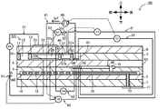
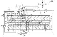
- FIG. 1 is a schematic cross-sectional view schematically showing an example of the configuration of the gas sensor 100 according to the embodiment of the present invention.
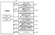
- FIG. 2 is a block diagram showing an electrical connection relationship between the control device 90 and each cell.
- the gas sensor 100 is attached to a pipe such as an exhaust gas pipe of an internal combustion engine.
- the gas sensor 100 detects the concentration of a specific gas such as NOx or ammonia in the gas to be measured, using the exhaust gas of the internal combustion engine as the gas to be measured.
- the gas sensor 100 measures the NOx concentration as a specific gas concentration.
- the gas sensor 100 includes a long rectangular parallelepiped sensor element 101, cells 21, 41, 50, 80 to 83 including a part of the sensor element 101, and a control device 90 that controls the entire gas sensor 100. And have.
- the sensor element 101 includes a first substrate layer 1, a second substrate layer 2, a third substrate layer 3, and a first solid electrolyte layer 4, each of which is composed of an oxygen ion conductive solid electrolyte layer such as zirconia (ZrO 2 ).
- the element has a laminated body in which six layers of the spacer layer 5 and the second solid electrolyte layer 6 are laminated in this order from the lower side in the drawing. Further, the solid electrolyte forming these six layers is a dense and airtight one.
- the sensor element 101 is manufactured, for example, by performing predetermined processing, printing of a circuit pattern, or the like on a ceramic green sheet corresponding to each layer, laminating them, and further firing and integrating them.
- a gas inlet 10 and a first gas inlet 10 are located between the lower surface of the second solid electrolyte layer 6 and the upper surface of the first solid electrolyte layer 4 on the tip end side (left end side in FIG. 1) of the sensor element 101.
- the third internal vacant space 61 is formed adjacent to each other in this order.
- the gas inlet 10, the buffer space 12, the first internal space 20, the second internal space 40, and the third internal space 61 have upper parts provided in a manner in which the spacer layer 5 is hollowed out.
- the space inside the sensor element 101 is defined by the lower surface of the second solid electrolyte layer 6, the lower portion is the upper surface of the first solid electrolyte layer 4, and the side portion is partitioned by the side surface of the spacer layer 5.
- the first diffusion-controlled unit 11, the second diffusion-controlled unit 13, and the third diffusion-controlled unit 30 are all provided as two horizontally long slits (the openings have a longitudinal direction in the direction perpendicular to the drawing). .. Further, the fourth diffusion-controlled unit 60 is provided as one horizontally long slit (the opening has a longitudinal direction in the direction perpendicular to the drawing) formed as a gap with the lower surface of the second solid electrolyte layer 6.
- the portion from the gas introduction port 10 to the third internal space 61 is also referred to as a gas distribution section to be measured.
- a reference gas introduction space 43 is provided at a position to be partitioned.
- the atmosphere is introduced into the reference gas introduction space 43 as a reference gas when measuring the NOx concentration.
- the atmosphere introduction layer 48 is a layer made of porous ceramics, and the reference gas is introduced into the atmosphere introduction layer 48 through the reference gas introduction space 43. Further, the atmosphere introduction layer 48 is formed so as to cover the reference electrode 42.
- the reference electrode 42 is an electrode formed so as to be sandwiched between the upper surface of the third substrate layer 3 and the first solid electrolyte layer 4, and as described above, the reference electrode 42 is connected to the reference gas introduction space 43 around the reference electrode 42.
- An air introduction layer 48 is provided. Further, as will be described later, the oxygen concentration (oxygen partial pressure) in the first internal space 20, the second internal space 40, and the third internal space 61 can be measured using the reference electrode 42. It is possible.
- the reference electrode 42 is formed as a porous cermet electrode (for example, a cermet electrode of Pt and ZrO 2 ).
- the gas introduction port 10 is a portion that is open to the external space, and the gas to be measured is taken into the sensor element 101 from the external space through the gas introduction port 10.
- the first diffusion-controlled unit 11 is a portion that imparts a predetermined diffusion resistance to the gas to be measured taken in from the gas introduction port 10.
- the buffer space 12 is a space provided for guiding the gas to be measured introduced from the first diffusion-controlled unit 11 to the second diffusion-controlled unit 13.
- the second diffusion-controlled unit 13 is a portion that imparts a predetermined diffusion resistance to the gas to be measured introduced from the buffer space 12 into the first internal space 20.
- the pressure fluctuation of the gas to be measured in the external space (if the gas to be measured is the exhaust gas of an automobile, the pulsation of the exhaust pressure).
- the gas to be measured which is rapidly taken into the sensor element 101 from the gas introduction port 10 by), is not directly introduced into the first internal space 20, but the first diffusion rate-determining unit 11, the buffer space 12, and the second.
- the pressure fluctuation of the gas to be measured is canceled through the diffusion rate-determining unit 13, the gas is introduced into the first internal space 20.
- the first internal space 20 is provided as a space for adjusting the oxygen partial pressure in the gas to be measured introduced through the second diffusion-controlled unit 13. The oxygen partial pressure is adjusted by operating the main pump cell 21.
- the main pump cell 21 has an inner pump electrode 22 having a ceiling electrode portion 22a provided on substantially the entire lower surface of the lower surface of the second solid electrolyte layer 6 facing the first internal space 20, and an upper surface of the second solid electrolyte layer 6.
- An electrochemical pump cell composed of an outer pump electrode 23 provided in a region corresponding to the ceiling electrode portion 22a so as to be exposed to an external space, and a second solid electrolyte layer 6 sandwiched between these electrodes. is there.
- the inner pump electrode 22 is formed across the upper and lower solid electrolyte layers (second solid electrolyte layer 6 and first solid electrolyte layer 4) that partition the first internal space 20, and the spacer layer 5 that provides the side wall.
- a ceiling electrode portion 22a is formed on the lower surface of the second solid electrolyte layer 6 that provides the ceiling surface of the first internal space 20, and a bottom portion is formed on the upper surface of the first solid electrolyte layer 4 that provides the bottom surface.
- a spacer layer in which electrode portions 22b are formed, and side electrode portions (not shown) form both side wall portions of the first internal space 20 so as to connect the ceiling electrode portions 22a and the bottom electrode portions 22b. It is formed on the side wall surface (inner surface) of No. 5 and is arranged in a structure in the form of a tunnel at the arrangement portion of the side electrode portion.
- the inner pump electrode 22 is an electrode containing a noble metal having catalytic activity (for example, at least one of Pt, Rh, Pd, Ru, and Ir).
- the inner pump electrode 22 also contains a noble metal having a catalytic activity suppressing ability (for example, Au) that suppresses the catalytic activity of the noble metal having a catalytic activity with respect to a specific gas.
- a noble metal having a catalytic activity suppressing ability for example, Au
- the inner pump electrode 22 that comes into contact with the gas to be measured is formed by using a material having a weakened reducing ability for a specific gas (NOx in this case) component in the gas to be measured.
- the inner pump electrode 22 is preferably an electrode made of a cermet containing a noble metal and an oxide having oxygen ion conductivity (ZrO 2 in this case). Further, the inner pump electrode 22 is preferably a porous body. In the present embodiment, the inner pump electrode 22 is a porous cermet electrode of Pt containing 1% Au and ZrO 2 .
- the outer pump electrode 23, like the inner pump electrode 22, is an electrode containing a noble metal having catalytic activity. Like the inner pump electrode 22, the outer pump electrode 23 may contain a noble metal having a catalytic activity suppressing ability, or may be an electrode made of cermet.
- the outer pump electrode 23 is preferably a porous body. In the present embodiment, the outer pump electrode 23 is a porous cermet electrode of Pt and ZrO 2 .
- a desired pump voltage Vp0 is applied between the inner pump electrode 22 and the outer pump electrode 23, and a pump current is applied in the positive or negative direction between the inner pump electrode 22 and the outer pump electrode 23.
- Vp0 the oxygen in the first internal space 20 can be pumped into the external space, or the oxygen in the external space can be pumped into the first internal space 20.
- the inner pump electrode 22 in order to detect the oxygen concentration (oxygen partial pressure) in the atmosphere in the first internal space 20, the inner pump electrode 22, the second solid electrolyte layer 6, the spacer layer 5, and the first solid electrolyte layer 4 are used.
- the third substrate layer 3 and the reference electrode 42 constitute an electrochemical sensor cell, that is, an oxygen partial pressure detection sensor cell 80 for controlling a main pump.
- the oxygen concentration (oxygen partial pressure) in the first internal space 20 can be known. Further, the pump current Ip0 is controlled by feedback-controlling the pump voltage Vp0 of the variable power supply 24 so that the voltage V0 becomes the target value. As a result, the oxygen concentration in the first internal space 20 can be maintained at a predetermined constant value.
- the third diffusion-controlled unit 30 imparts a predetermined diffusion resistance to the gas to be measured whose oxygen concentration (oxygen partial pressure) is controlled by the operation of the main pump cell 21 in the first internal space 20, and transfers the gas to be measured. It is a part leading to the second internal space 40.
- the auxiliary pump cell 50 is further applied to the gas to be measured introduced through the third diffusion-controlled unit 30. It is provided as a space for adjusting the oxygen partial pressure. As a result, the oxygen concentration in the second internal space 40 can be kept constant with high accuracy, so that the gas sensor 100 can measure the NOx concentration with high accuracy.
- the auxiliary pump cell 50 includes an auxiliary pump electrode 51 having a ceiling electrode portion 51a provided on substantially the entire lower surface of the second solid electrolyte layer 6 facing the second internal space 40, and an outer pump electrode 23 (outer pump electrode 23). It is an auxiliary electrochemical pump cell composed of a suitable electrode on the outside of the sensor element 101) and a second solid electrolyte layer 6.
- the auxiliary pump electrode 51 is arranged in the second internal space 40 in a structure having a tunnel shape similar to that of the inner pump electrode 22 provided in the first internal space 20. That is, the ceiling electrode portion 51a is formed on the second solid electrolyte layer 6 that provides the ceiling surface of the second internal space 40, and the first solid electrolyte layer 4 that provides the bottom surface of the second internal space 40 is formed. , The bottom electrode portion 51b is formed, and the side electrode portion (not shown) connecting the ceiling electrode portion 51a and the bottom electrode portion 51b provides a side wall of the second internal space 40 of the spacer layer 5. It has a tunnel-like structure formed on both walls.
- the auxiliary pump electrode 51 is also formed by using a material having a weakened reducing ability for the NOx component in the gas to be measured, similarly to the inner pump electrode 22.
- the auxiliary pump electrode 51 is an electrode containing a noble metal having catalytic activity (for example, at least one of Pt, Rh, Pd, Ru, and Ir).
- the auxiliary pump electrode 51 also contains a noble metal (for example, Au) having the above-mentioned ability to suppress catalytic activity.
- the auxiliary pump electrode 51 is preferably an electrode made of a cermet containing a noble metal and an oxide having oxygen ion conductivity (ZrO 2 in this case).
- the auxiliary pump electrode 51 is preferably a porous body.
- the auxiliary pump electrode 51 is a porous cermet electrode of Pt containing 1% Au and ZrO 2 .
- auxiliary pump cell 50 by applying a desired voltage Vp1 between the auxiliary pump electrode 51 and the outer pump electrode 23, oxygen in the atmosphere in the second internal space 40 is pumped out to the external space or outside. It is possible to pump from the space into the second internal space 40.
- the auxiliary pump electrode 51, the reference electrode 42, the second solid electrolyte layer 6, the spacer layer 5, and the first solid electrolyte are used.
- the layer 4 and the third substrate layer 3 constitute an electrochemical sensor cell, that is, an oxygen partial pressure detection sensor cell 81 for controlling an auxiliary pump.
- the auxiliary pump cell 50 pumps with the variable power supply 52 whose voltage is controlled based on the electromotive force (voltage V1) detected by the auxiliary pump control oxygen partial pressure detection sensor cell 81.
- V1 electromotive force
- the pump current Ip1 is used to control the electromotive force of the oxygen partial pressure detection sensor cell 80 for controlling the main pump.
- the pump current Ip1 is input to the oxygen partial pressure detection sensor cell 80 for controlling the main pump as a control signal, and the voltage V0 is controlled so that the third diffusion rate control unit 30 to the second internal space 40
- the gradient of the oxygen partial pressure in the gas to be measured introduced into the inside is controlled to be always constant.
- the oxygen concentration in the second internal space 40 is maintained at a constant value of about 0.001 ppm by the action of the main pump cell 21 and the auxiliary pump cell 50.
- the fourth diffusion-controlled unit 60 imparts a predetermined diffusion resistance to the gas to be measured whose oxygen concentration (oxygen partial pressure) is controlled by the operation of the auxiliary pump cell 50 in the second internal space 40, and transfers the gas to be measured. It is a part leading to the third internal space 61.
- the fourth diffusion-controlled unit 60 plays a role of limiting the amount of NOx flowing into the third internal space 61.
- the third internal space 61 is in the gas to be measured with respect to the gas to be measured introduced through the fourth diffusion rate-determining unit 60 after the oxygen concentration (oxygen partial pressure) is adjusted in advance in the second internal space 40. It is provided as a space for performing a process related to the measurement of the nitrogen oxide (NOx) concentration of. The measurement of the NOx concentration is mainly performed by the operation of the measurement pump cell 41 in the third internal space 61.
- the measurement pump cell 41 measures the NOx concentration in the gas to be measured in the third internal space 61.
- the measurement pump cell 41 includes a measurement electrode 44 provided on the upper surface of the first solid electrolyte layer 4 facing the third internal space 61, an outer pump electrode 23, a second solid electrolyte layer 6, and a spacer layer 5. , An electrochemical pump cell composed of the first solid electrolyte layer 4.
- the measurement electrode 44 is a porous cermet electrode made of a material having a reduction ability for a NOx component in the gas to be measured higher than that of the inner pump electrode 22.
- the measurement electrode 44 also functions as a NOx reduction catalyst that reduces NOx existing in the atmosphere in the third internal space 61.
- the measurement electrode 44 is an electrode containing a noble metal having catalytic activity (for example, at least one of Pt, Rh, Pd, Ru, and Ir).
- the content of the noble metal having the ability to suppress the catalytic activity described above in the measurement electrode 44 is smaller than the content in the main pump cell 21 and the auxiliary pump electrode 51.
- the measurement electrode 44 preferably does not contain a noble metal having an ability to suppress catalytic activity.
- the measurement electrode 44 is preferably an electrode made of a cermet containing a noble metal and an oxide having oxygen ion conductivity (ZrO 2 in this case). Further, the measurement electrode 44 is preferably a porous body. In the present embodiment, the measurement electrode 44 is a porous cermet electrode of Pt and Rh and ZrO 2 .
- oxygen generated by the decomposition of nitrogen oxides in the atmosphere around the measurement electrode 44 can be pumped out, and the amount generated can be detected as the pump current Ip2.
- an electrochemical sensor cell that is, a reference electrode 42 is used by the first solid electrolyte layer 4, the third substrate layer 3, the measurement electrode 44, and the reference electrode 42.
- the oxygen partial pressure detection sensor cell 82 for controlling the measurement pump is configured.
- the pulse power supply 46 is controlled based on the electromotive force (voltage V2) detected by the oxygen partial pressure detection sensor cell 82 for controlling the measurement pump.
- the pulse power supply 46 causes a pump current Ip2, which is repeatedly turned on and off, to flow between the measurement electrode 44 and the outer pump electrode 23.
- the pulse power supply 46 is configured as a current source.
- the measurement pump cell 41 operates according to the pump current Ip2.
- the gas to be measured guided into the second internal space 40 reaches the measurement electrode 44 in the third internal space 61 through the fourth diffusion-controlled unit 60 under the condition that the oxygen partial pressure is controlled. ..
- Nitrogen oxides in the gas to be measured around the measurement electrode 44 are reduced (2NO ⁇ N 2 + O 2 ) to generate oxygen.
- the generated oxygen is pumped by the measurement pump cell 41, and at that time, the voltage V2 detected by the measurement pump control oxygen partial pressure detection sensor cell 82 is set to the target state.
- the pump current Ip2 flowed by the pulse power supply 46 is controlled. Since the amount of oxygen generated around the measurement electrode 44 is proportional to the concentration of nitrogen oxides in the gas to be measured, the nitrogen oxides in the gas to be measured are used by using the pump current Ip2 in the measurement pump cell 41. The concentration will be calculated.
- the measurement electrode 44, the first solid electrolyte layer 4, the third substrate layer 3, and the reference electrode 42 are combined to form an oxygen partial pressure detecting means as an electrochemical sensor cell, the measurement electrode
- the electromotive force corresponding to the difference between the amount of oxygen generated by the reduction of the NOx component in the atmosphere around 44 and the amount of oxygen contained in the reference atmosphere can be detected, thereby detecting the NOx component in the gas to be measured. It is also possible to determine the concentration of.
- the electrochemical sensor cell 83 is composed of the second solid electrolyte layer 6, the spacer layer 5, the first solid electrolyte layer 4, the third substrate layer 3, the outer pump electrode 23, and the reference electrode 42.
- the electromotive force (voltage Vref) obtained by the sensor cell 83 makes it possible to detect the partial pressure of oxygen in the gas to be measured outside the sensor.
- the oxygen partial pressure is always kept at a constant low value (a value that does not substantially affect the measurement of NOx) by operating the main pump cell 21 and the auxiliary pump cell 50.
- the gas to be measured is supplied to the measurement pump cell 41. Therefore, it is necessary to know the NOx concentration in the gas to be measured based on the pump current Ip2 for pumping oxygen generated by the reduction of NOx from the pump cell 41 for measurement in substantially proportional to the concentration of NOx in the gas to be measured. Can be done.
- the sensor element 101 includes a heater unit 70 that plays a role of temperature adjustment for heating and keeping the sensor element 101 warm in order to enhance the oxygen ion conductivity of the solid electrolyte.
- the heater unit 70 includes a heater connector electrode 71, a heater 72, a through hole 73, a heater insulating layer 74, and a pressure dissipation hole 75.
- the heater connector electrode 71 is an electrode formed so as to be in contact with the lower surface of the first substrate layer 1. By connecting the heater connector electrode 71 to an external power source, power can be supplied to the heater unit 70 from the outside.
- the heater 72 is an electric resistor formed in a manner of being sandwiched between the second substrate layer 2 and the third substrate layer 3 from above and below.
- the heater 72 is connected to the heater connector electrode 71 via a through hole 73, and generates heat when power is supplied from the outside through the heater connector electrode 71 to heat and retain heat of the solid electrolyte forming the sensor element 101. ..
- the heater 72 is embedded in the entire area from the first internal space 20 to the third internal space 61, and the entire sensor element 101 can be adjusted to a temperature at which the solid electrolyte is activated. ing.
- the heater insulating layer 74 is an insulating layer formed on the upper and lower surfaces of the heater 72 by an insulator such as alumina.
- the heater insulating layer 74 is formed for the purpose of obtaining electrical insulation between the second substrate layer 2 and the heater 72 and electrical insulation between the third substrate layer 3 and the heater 72.
- the pressure dissipation hole 75 is a portion provided so as to penetrate the third substrate layer 3 and the atmosphere introduction layer 48 and communicate with the reference gas introduction space 43, and the internal pressure rises with the temperature rise in the heater insulating layer 74. It is formed for the purpose of alleviating.
- the control device 90 is a microprocessor provided with a CPU 92, a memory 94, and the like.
- the control device 90 detects the voltage V0 detected by the oxygen partial pressure detection sensor cell 80 for main pump control, the voltage V1 detected by the oxygen partial pressure detection sensor cell 81 for auxiliary pump control, and the oxygen partial pressure detection for measurement pump control.
- the voltage V2 detected by the sensor cell 82, the voltage Vref detected by the sensor cell 83, the pump current Ip0 detected by the main pump cell 21, and the pump current Ip1 detected by the auxiliary pump cell 50 are input. Further, the control device 90 outputs a control signal to the variable power supply 24 of the main pump cell 21, the variable power supply 52 of the auxiliary pump cell 50, and the pulse power supply 46 of the measurement pump cell 41 to control the cells 21, 50, 41.
- the control device 90 sets the variable power supply 24 based on the voltage V0 so that the voltage V0 becomes the target value (referred to as the target value V0 *) (that is, the oxygen concentration in the first internal space 20 becomes the target concentration).
- the pump voltage Vp0 is feedback-controlled. Therefore, the pump current Ip0 changes according to the oxygen concentration contained in the gas to be measured.
- control device 90 has a predetermined hypoxia so that the voltage V1 becomes a target value (referred to as a target value V1 *) (that is, the oxygen concentration of the second internal space 40 does not substantially affect the measurement of NOx).
- the voltage Vp1 of the variable power supply 52 is feedback-controlled based on the voltage V1) so as to have a concentration.
- the control device 90 sets the target value V0 * of the voltage V0 based on the pump current Ip1 so that the pump current Ip1 flowing by the voltage Vp1 becomes the target value (referred to as the target value Ip1 *) (feedback control). To do.
- the gradient of the oxygen partial pressure in the gas to be measured introduced from the third diffusion-controlled unit 30 into the second internal space 40 is controlled to be always constant. Further, the partial pressure of oxygen in the atmosphere in the second internal space 40 is controlled to a low partial pressure that does not substantially affect the measurement of NOx.
- the control device 90 sets the voltage V2 so that the voltage V2 becomes the target value (referred to as the target value V2 *) (that is, the oxygen concentration in the third internal space 61 becomes a predetermined low concentration). Based on this, the pump current Ip2 of the pulse power supply 46 is feedback-controlled. As a result, oxygen is pumped out from the third internal space 61 so that the oxygen generated by the reduction of NOx in the gas to be measured in the third internal space 61 becomes substantially zero. Then, the control device 90 derives the NOx concentration in the gas to be measured based on the pump current Ip2 as a value corresponding to the oxygen generated in the third internal space 61 derived from the specific gas (NOx in this case). To do.
- the target value V2 * that is, the oxygen concentration in the third internal space 61 becomes a predetermined low concentration
- the memory 94 stores a relational expression (for example, a linear function expression), a map, or the like as a correspondence relationship between the pump current Ip2 and the NOx concentration.
- a relational expression or map can be obtained experimentally in advance.
- the CPU 92 of the control device 90 is in a state of controlling the pump cells 21, 41, 50 described above and acquiring the voltages V0, V1, V2, Vref from the sensor cells 80 to 83 described above.
- the gas to be measured passes through the first diffusion-controlled unit 11, the buffer space 12, and the second diffusion-controlled unit 13, and the first internal space 20 To reach.
- the oxygen concentration of the gas to be measured is adjusted by the main pump cell 21 and the auxiliary pump cell 50, and the adjusted gas to be measured reaches the third internal space 61. To do.
- the CPU 92 detects the NOx concentration in the gas to be measured based on the correspondence relationship stored in the memory 94 with the pump current Ip2.
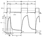
- FIG. 3 is an explanatory diagram showing time changes of the pump current Ip2 and the voltage V2.
- the upper part of FIG. 3 shows the time change of the pump current Ip2, and the lower part shows the time change of the voltage V2.
- the direction in which oxygen can be pumped from the periphery of the measurement electrode 44 to the periphery of the outer pump electrode 23 is positive, and in FIG. 3, the upward direction of the vertical axis is the positive direction.
- the positive direction of the pump current Ip2 is the direction of the arrow of the pump current Ip2 in FIG.
- the voltage V2 is positive when the potential of the reference electrode 42 is higher than that of the measurement electrode 44, and the upward direction of the vertical axis is the positive direction in FIG.
- the pulse power supply 46 of the measurement pump cell 41 causes a pump current Ip2 that is repeatedly turned on and off, that is, an intermittent pump current Ip2, to flow between the measurement electrode 44 and the outer pump electrode 23 to obtain oxygen around the measurement electrode 44. Pump out.
- the pump current Ip2 is a pulse-shaped waveform current that repeats on / off in the period T. For example, when the pump current Ip2 rises from 0A and turns on at time t1, the pump current Ip2 becomes the maximum current Ip2max, and the state continues until the time t4 when the on-time Ton elapses.
- the pump current Ip2 When the pump current Ip2 falls off at time t4, the pump current Ip2 becomes 0A until the time t7 when the off time Toff elapses.
- the actual pump current Ip2 requires a minute amount of time to fall from time t1 and fall from time t4, but is not shown in FIG. Further, even while the pump current Ip2 output by the pulse power supply 46 is off, a slight current may flow due to the influence of noise or the like, but the illustration is omitted in FIG.
- the CPU 92 of the control device 90 feedback-controls the pump current Ip2 of the pulse power supply 46 based on the voltage V2 so that the oxygen concentration in the third internal space 61 becomes a predetermined low concentration.
- the amount of oxygen pumped from the third internal space 61 by the pump current Ip2 during one cycle (cycle T) by the measurement pump cell 41 is the average value Ip2ave of the pump current Ip2 during one cycle (one point in the upper part of FIG. 3). (See chain line). Therefore, the CPU 92 outputs a control value to the pulse power supply 46 so as to change at least one of the parameters of, for example, the ratio of the Ton time to the period T (duty ratio), the period T, and the maximum current Ip2max, and the average value.
- the CPU 92 may output the average value Ip2ave as a control value to the pulse power supply 46, and the pulse power supply 46 may change at least one of the above parameters based on the control value.
- the CPU 92 outputs a duty ratio (or a change amount of the duty ratio) as a control value to the pulse power supply 46, and the pulse power supply 46 changes the duty ratio of the pump current Ip2 based on the control value. ..
- the CPU 92 controls the pulse power supply 46 so that the duty ratio of the pump current Ip2 becomes large (the Ton time becomes long without changing the period T) when the voltage V2 is smaller than the target value V2 *.
- the oxygen concentration in the third internal space 61 is further reduced. In FIG.
- the second Ton time (time t7 to t8) is twice as long as the first Ton time (time t1 to t4), and the second time is compared with the first cycle T. It shows how to double the average value Ip2ave in the period T of. Further, in FIG. 3, since the average value Ip2ave is doubled, the oxygen concentration in the third internal space 61 is reduced, and the voltage V2 is a value at time t9 rather than a value V2b at time t7. It shows that V2b'is larger.
- the pump current Ip2 controlled by the CPU 92 in this way eventually becomes a current corresponding to the oxygen generated in the third internal space 61 derived from the specific gas (NOx in this case). Therefore, the CPU 92 can derive the NOx concentration in the gas to be measured based on the pump current Ip2.
- the value of the parameter (duty ratio in this case) of the pump current Ip2 used by the CPU 92 as a control value is a value proportional to the NOx concentration in the gas to be measured. Therefore, if the correspondence between the two is stored in the memory 94, the CPU 92 can derive the NOx concentration based on the control value output to the pulse power supply 46 by itself and the correspondence stored in the memory 94. Similarly, the CPU 92 can also derive the NOx concentration using a value derived based on the control value (for example, the average value Ip2ave).
- FIG. 4 is a schematic cross-sectional view of the gas sensor 900 of the comparative example.
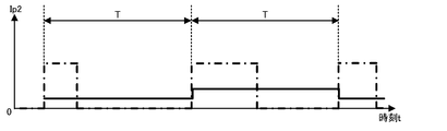
- FIG. 5 is an explanatory diagram showing a time change of the pump current Ip2 of the gas sensor 900.
- the same components as the gas sensor 100 are designated by the same reference numerals as those in FIG. 1, and detailed description thereof will be omitted.
- the definition of the direction of the pump current Ip2 is the same as that of the gas sensor 100, and in FIG. 5, the upward direction of the vertical axis is the positive direction. Further, in FIG. 5, for comparison, the waveform of the pump current Ip2 shown in FIG.
- the gas sensor 900 includes a measurement pump cell 941 instead of the measurement pump cell 41.
- the measurement pump cell 941 is the same as the measurement pump cell 41 except that it includes a variable power supply 946 instead of the pulse power supply 46.
- the variable power supply 946 applies a pump voltage Vp2 between the measurement electrode 44 and the outer pump electrode 23.
- a continuous pump current Ip2 flows through the measurement pump cell 941 as shown in FIG.
- the control device of the gas sensor 900 is similar to the control device 90 in that it inputs the voltages V0, V1, V2, Vref, the pump currents Ip0 and Ip1, and outputs the control signals to the variable power supplies 24 and 52. I do.
- the control device of the gas sensor 900 feedback-controls the voltage Vp2 of the variable power supply 946 so that the voltage V2 becomes the target value based on the input voltage V2.
- oxygen is released from the third internal space 61 by the measurement pump cell 941 so that the oxygen generated by the reduction of NOx in the gas to be measured in the third internal space 61 becomes substantially zero. It is pumped out.
- the control device performs feedback control of the voltage Vp2 every cycle T as in FIG. 3, the pump current Ip2 flowing in the measurement pump cell 941 changes every cycle T as shown in FIG. 5 while continuously flowing. I will do it.
- the actual pump current Ip2 requires a minute time to complete the change for each period T, but the illustration is omitted in FIG.
- the control device of the gas sensor 900 acquires the pump current Ip2 from the measurement pump cell 941 and calculates the NOx concentration in the gas to be measured based on the pump current Ip2.
- the CPU 92 can adjust the oxygen concentration in the third internal space 61 even when the continuous pump current Ip2 is not passed as in the comparative example and the intermittent pump current Ip2 is passed as in the present embodiment.
- the NOx concentration can also be measured.
- the gas sensor 100 uses the pulse power supply 46 which is a current source, the control value itself output by the CPU 92 to the pulse power supply 46 becomes a value corresponding to the pump current Ip2. Therefore, the CPU 92 can grasp the pump current Ip2 based on the control value determined by itself and derive the NOx concentration without inputting the pump current Ip2 from the measurement pump cell 41.
- the gas sensor 100 by passing the intermittent pump current Ip2 through the measurement pump cell 41, the gas sensor 100 is used as compared with the case where the continuous pump current Ip2 is passed through the measurement pump cell 941 as in the gas sensor 900. It is possible to suppress the change in the catalytic activity of the measurement electrode 44 due to the above. The reason for this is considered as follows.
- oxygen becomes oxygen ions (O 2 + 4e - ⁇ 2O 2-).
- Oxygen ions act as electron carriers, pass through the solid electrolyte layer (here, each layer 4 to 6), and head toward the outer pump electrode 23.
- the pump current Ip2 is a continuous current, a reaction in which some noble metals (here, Pt and Rh) in the measuring electrode 44 are oxidized and an oxidized noble metal (here, PtO, PtO 2 ) are oxidized.
- the area of the three-phase interface between the measurement electrode 44 and the pores in the measurement electrode 44 and the first solid electrolyte layer 4 or the area of the two-phase interface between the measurement electrode 44 and the first solid electrolyte layer 4 is reduced. Therefore, it is conceivable that the catalytic activity of the measurement electrode 44 decreases.
- the pump cell 41 is intermittently pumped so as to have the same average current (average value Ip2ave) as the continuous pump current Ip2 of the gas sensor 900.
- the pump current Ip2 (here, the maximum current Ip2max) flowing through the measurement electrode 44 when the gas sensor 100 is on (for example, at times t1 to t4 in FIG. 3) is a larger value than the continuous pump current Ip2 in the gas sensor 900. (See Figures 3 and 5).
- the gas sensor 100 of the present embodiment can suppress such a decrease in the detection sensitivity of NOx concentration due to use. Therefore, the gas sensor 100 of the present embodiment can maintain the measurement accuracy even if it is used for a long period of time, and can extend the life.
- the voltage V2 is a voltage between the measurement electrode 44 and the reference electrode 42, and is basically a value corresponding to the oxygen concentration in the third internal space 61.
- the voltage V2 since the potential of the measuring electrode 44 changes intermittently when the pulse power supply 46 applies the intermittent pump current Ip2, the voltage V2 also changes periodically so as to pulsate under the influence of this.
- the waveform of the voltage V2 has a first period in which the change is generated by turning on the pump current Ip2 and a second period in which the change is contained by turning off the pump current Ip2. For example, in FIG.
- the voltage V2 starts changing at time t1 (here, it starts rising), becomes the most changed value V2a (here, the maximum value) at time t4, and starts to settle from time t4 (here, standing). (Beginning to fall), the value becomes V2b (here, the minimum value) at which the change is most subdued at time t7.
- the voltage V2 from the value V2b to the value V2a in the period of one cycle T of the pump current Ip2 is set to 0% to 100%, and the first period and the second period of the voltage V2 are determined based on this.
- the period in which the voltage V2 is 90% or more is defined as the first period, and this length is defined as the first hour T1.
- the second period is the period (time t6 to t7) from when the pump current Ip2 is turned off and the voltage V2 becomes 10% or less until the voltage V2 starts to rise when the pump current Ip2 is turned on in the next cycle. Is the second time T2.
- the voltage V2 has the most changed value V2a for the first time at the time t4 when the pump current Ip2 is turned off, but when the on-time Ton is long, the voltage V2 reaches the value V2a before the time t4 and is in that state. May continue until time t4.
- the voltage V2 fluctuates periodically under the influence of the pump current Ip2. Then, during the second period, the influence of the pump current Ip2 on the voltage V2 is smaller than that during the first period. Therefore, the voltage V2 during the second period is a value that more accurately represents the oxygen concentration in the third internal space 61 than the voltage V2 during the first period. For this reason, it is preferable that the CPU 92 controls the pump current Ip2 as described above based on the voltage V2 during the second period. By doing so, the CPU 92 can accurately bring the oxygen concentration of the third internal space 61 close to a predetermined low concentration, and can accurately derive the NOx concentration in the gas to be measured.
- the CPU 92 acquires the voltage V2 during the second period, compares the acquired voltage V2 with the target value V2 *, and determines the control value to be output to the pulse power supply 46. Further, as shown in FIG. 3, the voltage V2 changes with the passage of time even during the second period, and the influence of the pump current Ip2 tends to decrease as it approaches the end of the second period (time t7 in FIG. 3). .. This is considered to be due to the influence of the capacitance component in the measurement pump cell 41 such as the capacitance component of the measurement electrode 44. Therefore, it is preferable that the CPU 92 controls the pump current Ip2 based on the voltage V2 at the latest possible timing during the second period. For example, the CPU 92 may control the pump current Ip2 based on the voltage V2 at any timing in the latter half of the second period.
- the CPU 92 may control the pump current Ip2 based on the voltage V2 during the second period in each of the plurality of cycles T (for example, based on the average value of the plurality of voltages V2 acquired in different cycles). For example, if the pump current Ip2 is controlled based only on the voltage V2 during the second period of one cycle, the actual average value Ip2ave oscillates or diverges with respect to the correct average value Ip2ave corresponding to the NOx concentration. The control of the pump current Ip2 may become unstable. On the other hand, when the CPU 92 controls the pump current Ip2 based on the average value of the voltage V2 during the second period in each of the plurality of cycles T, the control is less likely to become unstable.
- the CPU 92 stores the voltage V2 at a predetermined timing during the second period in the memory 94 for each cycle T, and the average value of the voltage V2 for a plurality of times (for example, three times) stored most recently. Based on the above, the pump current Ip2 was controlled.
- the CPU 92 may control the main pump cell 21 based on the voltage V0 during the second period of the voltage V2. Similarly, the CPU 92 may control the auxiliary pump cell 50 based on the voltage V1 during the second period of the voltage V2. The CPU 92 may set the target value V0 * based on the pump current Ip1 during the second period of the voltage V2.
- the first substrate layer 1, the second substrate layer 2, the third substrate layer 3, the first solid electrolyte layer 4, the spacer layer 5 and the second solid electrolyte layer 6 of the present embodiment correspond to the element main body of the present invention, and are mainly
- the pump cell 21, the auxiliary pump cell 50, and the measurement pump cell 41 correspond to the pump cells, respectively
- the inner pump electrode 22, the auxiliary pump electrode 51, and the measurement electrode 44 correspond to the inner electrodes
- the outer pump electrode 23 corresponds to the outer electrode. ..
- the inner pump electrode 22 corresponds to the inner main pump electrode
- the auxiliary pump electrode 51 corresponds to the inner auxiliary pump electrode
- the measurement electrode 44 corresponds to the inner measurement electrode
- the outer pump electrode 23 corresponds to the outer main pump electrode and the outer side. It corresponds to the auxiliary pump electrode and the outer measurement electrode
- the third internal space 61 corresponds to the measurement chamber.
- the pump current Ip2 corresponds to the measurement pump current
- the voltage V2 corresponds to the measurement voltage
- the measurement pump control oxygen partial pressure detection sensor cell 82 corresponds to the measurement voltage detection means
- the control device 90 measures. Corresponds to the pump cell control means and the specific gas concentration detecting means.
- the gas sensor 100 of the present embodiment described in detail above includes a main pump cell 21, an auxiliary pump cell 50, and a measurement pump cell 41 as one or more pump cells.
- the main pump cell 21 has an inner pump electrode 22 arranged in the first internal space 20 and an outer pump electrode 23, and pumps oxygen from the first internal space 20.
- the auxiliary pump cell 50 has an auxiliary pump electrode 51 arranged in a second internal space 40 on the downstream side of the first internal space 20, and an outer pump electrode 23, and has a second internal space 40. Pump out oxygen.
- the measurement pump cell 41 has a measurement electrode 44 arranged in a third internal space 61 on the downstream side of the second internal space 40, and an outer pump electrode 23, and NOx in the gas to be measured. Oxygen generated in the third internal space 61 is pumped out.
- the measurement pump cell 41 pumps out oxygen around the measurement electrode 44 by flowing a pump current Ip2 that is repeatedly turned on and off between the measurement electrode 44 and the outer pump electrode 23.
- the gas sensor 100 changes the catalytic activity of the measuring electrode 44 with use (here, as compared with the case where a continuous pump current Ip2 is passed between the measuring electrode 44 and the outer pump electrode 23 as in the gas sensor 900. Can suppress the decrease).
- the pump current Ip2 that is repeatedly turned on and off has a higher peak value (maximum current Ip2max) than the continuous pump current Ip2, the signal noise ratio (S / N ratio) becomes higher and is resistant to noise. Become.
- the measurement pump cell 41 is operated by using the intermittent pump current (here, the pump current Ip2).
- the change in the catalytic activity of the measurement electrode 44 has a greater influence on the detection sensitivity of the NOx concentration of the gas sensor 100 than, for example, the change in the catalytic activity of the inner pump electrode 22 and the auxiliary pump electrode 51. Therefore, by suppressing the change in the catalytic activity of the measurement electrode 44, it is easy to suppress the decrease in the detection sensitivity.
- the CPU 92 controls the pump current Ip2 so that the oxygen concentration in the third internal space 61 becomes a predetermined low concentration based on the voltage V2 during the second period. Then, the CPU 92 detects the NOx concentration in the gas to be measured based on the pump current Ip2. As a result, the CPU 92 can accurately detect the NOx concentration.
- the intermittent pump current Ip2 is a current having one rectangular wave per cycle (rectangular single pulse current) as shown in FIG. 3, but is not limited to this.
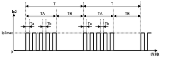
- the pulse power supply 46 may use a burst pulse current as shown in FIG. 6 as an intermittent pump current Ip2.
- the CPU 92 determines the ratio (duty ratio) of the oscillation period TA to the period T (burst period), the period T, the number of pulses in one cycle (5 times in FIG. 6), and the time of one oscillation (pulse).
- a control value is output to the pulse power supply 46 so as to change at least one of the parameters of Ta, the pulse period (Ta + Tb), and the maximum current Ip2max, and the average value Ip2ave of the pump current Ip2 during one cycle is changed. May be good.
- the first period of the voltage V2 is included in the oscillation period TA, and the second period is included in the non-oscillation period TB. More specifically, when the pump current Ip2 is a burst pulse current, the oscillation period TA is regarded as the period when the pump current Ip2 is on (time t1 to t4 in FIG. 3), and the non-oscillation period TB is the pump current Ip2. Is regarded as an off period (time t4 to t7 in FIG. 3), and the second period is defined in the same manner as in the above-described embodiment.
- the pulse power supply 46 has a square wave pulse current as a pump current Ip2 as shown in FIG. 3, but is not limited to a square wave (square wave), but a sine wave half wave, a triangular wave, and a sawtooth wave.
- a pulse current such as a waveform shape at the time of discharge may be passed, or a pulse current having a waveform in which one or more of these are combined may be passed.
- the period T of the intermittent pump current Ip2 in FIGS. 3 and 6 may be, for example, 0.1 s or less (frequency is 10 Hz or more) or 0.02 s or less (frequency). Is 50 Hz or more), or 0.001 s or less (frequency is 100 Hz or more).
- the control device 90 outputs the derived NOx concentration to another device such as the engine ECU of the vehicle for each predetermined cycle Tout, it is preferable that the cycle T is 1/10 or less of the cycle Tout.
- the measurement pump cell 41 is operated by using an intermittent pump current (here, the pump current Ip2), but the present invention is limited to this. Absent. At least one of the pump cells included in the gas sensor 100 may operate with an intermittent pump current. For example, the main pump cell 21 and the measurement pump cell 41 may also be operated with an intermittent pump current.
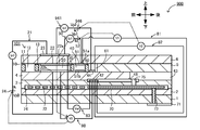
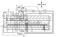
- FIG. 7 is a schematic cross-sectional view of the modified gas sensor 200. Of the gas sensor 200, the same components as the gas sensor 100 are designated by the same reference numerals as those in FIG. 1, and detailed description thereof will be omitted.
- the gas sensor 200 includes a main pump cell 221 instead of the main pump cell 21, and an auxiliary pump cell 250 instead of the auxiliary pump cell 50.
- the main pump cell 221 is the same as the main pump cell 21 except that it includes a pulse power supply 224 which is a current source similar to the pulse power supply 46 instead of the variable power supply 24.
- the auxiliary pump cell 250 is the same as the auxiliary pump cell 50 except that the variable power supply 52 is replaced with the pulse power supply 252, which is a current source similar to the pulse power supply 46.
- the change in the catalytic activity of the inner pump electrode 22 due to the use of the gas sensor 100 can be suppressed by passing an intermittent pulse current through the main pump cell 221.
- the pulse power supply 252 passes an intermittent pulse current, it is possible to suppress a change in the catalytic activity of the auxiliary pump electrode 51 due to the use of the gas sensor 100.
- the inner pump electrode 22 contains a noble metal having a catalytic activity and a noble metal having an ability to suppress the catalytic activity. Therefore, when the noble metal in the inner pump electrode 22 is oxidized and evaporated, the catalytic activity of the inner pump electrode 22 decreases and the oxygen pumping ability of the main pump cell 21 decreases, or the catalytic activity increases and the first It is considered that the inner pump electrode 22 decomposes NOx in the internal space 20.
- the gas sensor 100 since it is not preferable for the gas sensor 100, it is significant to suppress such a change (decrease or increase) in the catalytic activity of the inner pump electrode 22.
- the auxiliary pump electrode 51 since it is not preferable for the gas sensor 100, it is significant to suppress such a change (decrease or increase) in the catalytic activity of the inner pump electrode 22.
- the auxiliary pump electrode 51 when the main pump cell 221 pumps oxygen from the periphery of the outer pump electrode 23 into the first internal space 20 by an intermittent pulse current, it is considered that the change in the catalytic activity of the outer pump electrode 23 can be suppressed. ..
- the control device 90 has the main pump cell 221 outside.
- the pulse power supply 224 is controlled so as to draw oxygen from the periphery of the pump electrode 23 into the first internal space 20.
- the control device 90 reverses the positive / negative of the pulse of the pulse power supply 224 to determine whether the main pump cell 221 pumps oxygen from the first internal space 20 or pumps oxygen into the first internal space 20. You may switch.
- a negative pulse current a pulse in which the current value drops from a value of 0 to a minus value
- the pump current Ip0 may be directly changed by the current source by using a current source instead of the variable power supply 24. ..
- the pump current Ip1 is directly changed by the current source using a current source instead of the variable power supply 52. You may.
- the sensor element 101 of the gas sensor 100 includes a first internal space 20, a second internal space 40, and a third internal space 61, but is not limited thereto.
- the third internal space 61 may not be provided.
- a gas introduction port 10 and a first diffusion rate-determining unit 11 are provided between the lower surface of the second solid electrolyte layer 6 and the upper surface of the first solid electrolyte layer 4.
- the buffer space 12, the second diffusion rate-determining section 13, the first internal space 20, the third diffusion rate-determining section 30, and the second internal space 40 are adjacent to each other in this order. ..
- the measurement electrode 44 is arranged on the upper surface of the first solid electrolyte layer 4 in the second internal space 40.
- the measuring electrode 44 is covered with a fourth diffusion-controlled unit 45.
- the fourth diffusion-controlled unit 45 is a film made of a ceramic porous body such as alumina (Al 2 O 3 ).
- the fourth diffusion-controlled unit 45 plays a role of limiting the amount of NOx flowing into the measurement electrode 44, similarly to the fourth diffusion-controlled unit 60 of the above-described embodiment.
- the fourth diffusion-controlled unit 45 also functions as a protective film for the measurement electrode 44.
- the ceiling electrode portion 51a of the auxiliary pump electrode 51 is formed up to directly above the measurement electrode 44.
- the NOx concentration can be detected based on the pump current Ip2 as in the above-described embodiment.
- the periphery of the measurement electrode 44 (inside the fourth diffusion-controlled unit 45) functions as a measurement chamber.
- the outer pump electrode 23 also serves as the outer main pump electrode of the main pump cell 21, the outer auxiliary pump electrode of the auxiliary pump cell 50, and the outer measurement electrode of the measurement pump cell 41, but the present invention is not limited to this. Any one or two of the outer main pump electrode, the outer auxiliary pump electrode, and the outer measurement electrode may be provided outside the sensor element 101 separately from the outer pump electrode 23.
- the element main body of the sensor element 101 is a laminate having a plurality of solid electrolyte layers (layers 1 to 6), but the present invention is not limited to this.
- the element main body of the sensor element 101 may include at least one oxygen ion conductive solid electrolyte layer, and may be provided with a gas flow section to be measured inside.
- layers 1 to 5 other than the second solid electrolyte layer 6 may be layers made of a material other than the solid electrolyte layer (for example, a layer made of alumina).
- each electrode of the sensor element 101 may be arranged on the second solid electrolyte layer 6.
- the reference gas introduction space 43 is provided in the spacer layer 5 instead of the first solid electrolyte layer 4, and the atmosphere introduction layer 48 is provided between the first solid electrolyte layer 4 and the third substrate layer 3 instead of being provided in the second solid. It may be provided between the electrolyte layer 6 and the spacer layer 5, and the reference electrode 42 may be provided behind the third internal space 61 and on the lower surface of the second solid electrolyte layer 6.
- the gas sensor 100 detects the NOx concentration as the specific gas concentration, but the present invention is not limited to this, and other oxide concentrations may be used as the specific gas concentration.
- the specific gas is an oxide
- oxygen is generated when the specific gas itself is reduced in the third internal space 61 as in the above-described embodiment, so that the CPU 92 detects a detection value (for example, average) according to the oxygen.
- a specific gas concentration can be detected based on the value Ip2ave).
- the specific gas may be a non-oxide such as ammonia.
- the specific gas When the specific gas is non-oxide, the specific gas is converted to an oxide, for example, in the first internal space 20 (for example, if it is ammonia, it is oxidized and converted to NO), so that the converted oxide is converted to NO. Since oxygen is generated when the gas is reduced in the third internal space 61, the CPU 92 can acquire a detection value corresponding to the oxygen and detect the specific gas concentration. As described above, regardless of whether the specific gas is an oxide or a non-oxide, the gas sensor 100 can detect the specific gas concentration based on the oxygen generated in the third internal space 61 derived from the specific gas. ..
- the control device 90 sets (feedback control) the target value V0 * of the voltage V0 based on the pump current Ip1 so that the pump current Ip1 becomes the target value Ip1 *, and the voltage V0 is the target value.
- the pump voltage Vp0 is feedback-controlled so as to be V0 *, other control may be performed.
- the control device 90 may feedback control the pump voltage Vp0 based on the pump current Ip1 so that the pump current Ip1 becomes the target value Ip1 *.
- control device 90 directly controls the pump voltage Vp0 based on the pump current Ip1 without acquiring the voltage V0 from the main pump control oxygen partial pressure detection sensor cell 80 and setting the target value V0 * ( As a result, the pump current Ip0 may be controlled).
- the voltage Vp2 of the pulse power supply 46 is controlled so that the voltage V2 detected by the oxygen partial pressure detection sensor cell 82 for measuring pump control becomes the target value V2 *, and the pump current Ip2 at this time is controlled.
- the NOx concentration in the gas to be measured was calculated using, but the present invention is not limited to this.
- the CPU 92 feedback-controls the measurement pump cell 41 (for example, controls the voltage Vp2) so that the average value Ip2ave shown in FIG. 3 becomes a predetermined target value Ip2 *, and uses the voltage V2 at this time to control the NOx concentration. May be calculated.
- the third internal space has an almost constant flow rate.
- Oxygen will be pumped out from 61. Therefore, the oxygen concentration in the third internal space 61 changes according to the amount of oxygen generated by reducing NOx in the gas to be measured in the third internal space 61, and the voltage V2 changes accordingly. Therefore, the voltage V2 becomes a value corresponding to the NOx concentration in the gas to be measured. Therefore, the NOx concentration can be calculated based on this voltage V2.
- the correspondence between the voltage V2 and the NOx concentration may be stored in the memory 94 in advance.
- the CPU 92 uses the value of the voltage V2 during the second period as the value of the voltage V2 for calculating the NOx concentration. As described above, since the influence of the pump current Ip2 on the voltage V2 is small during the second period, the specific gas concentration in the gas to be measured can be accurately detected by using the voltage V2 during the second period. ..
- the current waveform when the pump current Ip2 is used as the pulse current is shown in a rectangular shape, but as described above, a minute time is required for the rise and fall of the pulse current. That is, the pulse current actually has a rise time and a fall time, and the pulse current does not become a perfect rectangle. Therefore, for example, as shown in the enlarged view of the pulse current in the upper part of FIG. 9, when the pulse width of the pulse current is too small, the actual peak value of the pulse current (the peak value of the waveform of the broken line) is affected by the rise time. ) May not reach the peak value of the ideal rectangular waveform (the peak value of the solid line waveform).
- the CPU 92 performs feedback control based on the voltage V2 and the target value V2 * described above, and outputs a control value to the pulse power supply 46 in order to set the average value Ip2ave to a certain target value (referred to as the target average current Ip2ave *). Even if this is done, the actual average value Ip2ave will be lower than the theoretical average value Ip2ave, so that the actual average value Ip2ave deviates from the target average current Ip2ave *. Therefore, the control device 90 may not be able to correctly control the measurement pump cell 41, or the S / N ratio of the pump current Ip2 may decrease.
- the control device 90 controls the measurement pump cell 41 so that the pulse width of the pump current Ip2 does not become too small so that the actual peak value does not reach the peak value of the ideal rectangular waveform.
- the control device 90 preferably controls the pump current Ip2 within a range in which the pulse width of the pump current Ip2 does not become less than a predetermined lower limit value.
- the control device 90 preferably reduces the number of pulses when the target average current Ip2ave * is small. By reducing the number of pulses, the pulse width is increased in order to allow the pump current Ip2 to flow according to the target average current Ip2ave *, so that it is possible to prevent the pulse width from becoming smaller.
- a predetermined lower limit value for example, the control device 90 preferably reduces the number of pulses when the target average current Ip2ave * is small. By reducing the number of pulses, the pulse width is increased in order to allow the pump current Ip2 to flow according to the target average current Ip2ave *, so that it is possible to prevent the pulse width from becoming smaller.
- FIG. 9 shows a case where the pump current Ip2 is a burst pulse current as in FIG. 6, and the number of pulses in one cycle of the upper waveform is 6, whereas the number of pulses is 2 in the lower waveform. It is reduced to. Instead, in the lower waveform of FIG.
- the pulse width (time Ta of one pulse) is tripled of the upper waveform, and the theoretical average value Ip2ave does not change between the upper waveform and the lower waveform. I am doing it.
- the burst pulse interval (Tb in the figure) is also large (specifically, three times).
- the process of controlling 41 is repeatedly executed. At this time, when the value of the determined target average current Ip2ave * is a value included in the predetermined low current region (for example, a value less than a predetermined threshold value), the value of the determined target average current Ip2ave * is a predetermined low.
- the measurement pump cell 41 is controlled so that the pump current Ip2 with a reduced number of pulses flows as compared with the case where the value is not included in the current region (for example, a value equal to or higher than a predetermined threshold value).
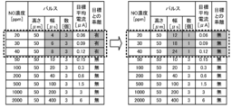
- FIG. 10 is an example of a comparison result between the case where the control for reducing the number of pulses is not performed (the table on the left side) and the case where the control is performed (the table on the right side). In FIG.
- the pulse height of the pump current Ip2 determined by the control device 90 so that the target value Ip2ave becomes the target average current Ip2ave *. It shows the width and number.
- the pump current Ip2 is a burst pulse current as in FIGS. 6 and 9, the pulse height corresponds to Ip2max in FIGS. 6 and 9, the width corresponds to Ta in FIGS. 6 and 9, and the number is in one cycle. Corresponds to the number of pulses.
- the presence or absence of a discrepancy between the actual average value Ip2ave and the target average current Ip2ave * when the determined pulse height, width, and number of pump currents Ip2 are passed is also shown.
- the number of pulses is fixed at 3 without controlling to reduce the number of pulses
- the target average current Ip2ave * is less than 0.15 ⁇ A
- the determined pulse width is less than 10 ⁇ A. It became a small value.
- the actual average value Ip2ave in this case is smaller than the theoretical average value Ip2ave, and there is a deviation from the target average current Ip2ave *.
- the control device 90 controls to reduce the number of pulses to 1.
- the number of determined pulses is reduced to 1, and the pulse width is 10 ⁇ m or more as a value required to achieve the target average current Ip2ave *.
- the pulse width was determined to be larger than the table on the left side of FIG. 10, and the pulse width was not less than 10 ⁇ m.
- FIG. 10 also shows the NO concentration corresponding to the target average current Ip2ave *.
- the target average current Ip2ave * is less than 0.15 ⁇ A, that is, when the NO concentration is as low as less than 50 ppm
- the actual average value Ip2ave deviates from the target average current Ip2ave *.
- the measurement pump cell 41 cannot be controlled correctly, or the S / N ratio of the pump current Ip2 decreases.
- such a problem is unlikely to occur even when the NO concentration is as low as less than 50 ppm.
- the control device 90 preferably controls the pump current Ip2 within a range in which the pulse width of the pump current Ip2 does not become less than a predetermined lower limit value, but similarly, the interval between the pulses of the pump current Ip2 ( It is preferable to control the pump current Ip2 within a range in which Tb) in FIG. 9 does not fall below a predetermined lower limit value. This is because if the pulse interval is too small, the rise of the next pulse occurs before the pulse current completely drops, and the same problem as when the pulse width is too small occurs. Further, in the examples of FIGS. 9 and 10, the case where the pump current Ip2 is the burst pulse current has been described as an example, but even when the pump current Ip2 as shown in FIG. 3 is not the burst pulse current, the pulse width (Ton in FIG. 3). ) And the pulse interval (Toff in FIG. 3) do not fall below a predetermined lower limit, and the pump current Ip2 is preferably controlled.
- control device 90 and the power supplies 24, 46, 52 are shown separately in FIG. 2, but the power supplies 24, 46, 52 can also be regarded as a part of the control device 90.
- Example 1 The gas sensor 100 shown in FIGS. 1 and 2 described above was manufactured and used as Example 1.
- the sensor element 101 was created as follows. First, zirconia particles to which 4 mol% of the stabilizer yttria was added, an organic binder, a dispersant, a plasticizer, and an organic solvent were mixed, and a ceramic green sheet corresponding to each of the layers 1 to 6 was formed by tape molding. .. Next, the ceramic green sheet corresponding to each layer is perforated as necessary, and the pattern of the conductive paste for forming each electrode and circuit is screen-printed, and then laminated and crimped. Was used as a crimping body.
- the pattern for the measurement electrode 44 was formed by screen-printing a conductive paste in which zirconia particles and an organic binder were mixed with the precious metals Pt and Rh. Then, an unfired laminate having the size of the sensor element 101 was cut out from the crimped body and fired to obtain the sensor element 101.
- Each power source and control device 90 were electrically connected to the manufactured sensor element 101 to manufacture the gas sensor 100 of Example 1.
- the pump current Ip2 applied by the pulse power supply 46 was a rectangular single pulse current shown in FIG. 3, the frequency was 100 Hz (period T was 0.1 s), and Ip2max was 50 ⁇ A.
- Example 2 A gas sensor 100 similar to that of Example 1 was produced and used as Example 2 except that the pump current Ip2 applied by the pulse power supply 46 was changed.
- the pump current Ip2 applied by the pulse power supply 46 is the burst pulse current shown in FIG. 6, and the frequency is 100 Hz (cycle T is 0.1 s), the number of pulses in one cycle is 5, and the cycle T (burst cycle).
- the ratio (duty ratio) of the oscillation period TA to occupy was set to 50%.
- Example 3 A gas sensor 100 similar to that of Example 1 was produced and used as Example 3 except that the frequency was set to 200 Hz (period T was 0.05 s).
- Example 4 A gas sensor 100 similar to that of Example 2 was produced and used as Example 4 except that the frequency was set to 200 Hz (period T was 0.05 s).
- Comparative Example 1 The gas sensor 900 of the comparative example shown in FIG. 4 was produced and used as Comparative Example 1. That is, the case where a continuous current is passed as the pump current Ip2 is set as Comparative Example 1.
- the gas sensor 900 of Comparative Example 1 was the same as that of Example 1 except that the measurement pump cell 941 shown in FIG. 4 was provided instead of the measurement pump cell 41.
- the control device 90 controls the pump cells 21, 41, and 50 described above, and the voltages V0, V1, V2, and Vref described above are acquired from the sensor cells 80 to 83 described above.
- the first model gas having a base gas of nitrogen and a NO concentration of 500 ppm is passed through the pipe, waits for the control value from the control device 90 to the pulse power supply 46 to stabilize, and the average after stabilization.
- the value Ip2ave was measured as the initial value Ia500 of the detection sensitivity of the gas sensor with respect to NO of 500 ppm.
- a 40-minute operation pattern composed of an engine speed of 1500 to 3500 rpm and a load torque of 0 to 350 Nm was repeated until 1000 hours had passed.
- the gas temperature at that time was 200 ° C. to 600 ° C., and the NOx concentration was 0 to 1500 ppm.
- the control device 90 continued to control each pump cell and acquire each voltage.
- the average value Ip2ave was measured by the same method as the initial value Ia500, and the value was set to the value Ib500 after the durability test.
- the sensitivity change rate at a NO concentration of 500 ppm [1- (value Ib500 after durability test / initial value Ia500)] ⁇ 100%
- the NO sensitivity change rate of the pump current Ip2 before and after the durability test of the gas sensor of Example 1 [ %] was derived.
- the NO sensitivity linearity after the durability test of the gas sensor of Example 1 was derived as follows. First, as with the value Ib500 after the durability test, for the second model gas in which the base gas is nitrogen and the NO concentration is 0 ppm, the average value Ip2ave after the control value is stabilized is measured, and the average value Ip2ave after the durability test is measured. The value was Ib0. Further, for the third model gas in which the base gas is nitrogen and the NO concentration is 1500 ppm, the average value Ip2ave after the control value became stable was measured and set to the value Ib1500 after the durability test.
- the NO sensitivity change rate [%] of the pump current Ip2 before and after the durability test and the NO sensitivity linearity rate [%] after the durability test were derived.
- the NO sensitivity change rate [%] and the NO sensitivity linear rate [%] were derived in the same manner except that the value of the pump current Ip2 after stabilization was measured instead of the average value Ip2ave. ..
- Table 1 shows the frequencies and pulse methods, NO sensitivity change rate, and NO sensitivity linear rate of Examples 1 to 4 and Comparative Example 1, respectively.
- the NO sensitivity linearity after the durability test is closer to 100%, the linearity of the NO sensitivity between the three points of the NO concentration of 0 ppm, 500 ppm, and 1500 ppm is closer to the ideal state even after the durability test. This means that the decrease in detection accuracy due to the use of the gas sensor is suppressed.
- the present invention can be used for a gas sensor that detects a specific gas concentration such as NOx in a gas to be measured such as exhaust gas of an automobile.
Landscapes
- Chemical & Material Sciences (AREA)
- Life Sciences & Earth Sciences (AREA)
- Health & Medical Sciences (AREA)
- Pathology (AREA)
- General Physics & Mathematics (AREA)
- Immunology (AREA)
- Physics & Mathematics (AREA)
- Analytical Chemistry (AREA)
- Biochemistry (AREA)
- General Health & Medical Sciences (AREA)
- Chemical Kinetics & Catalysis (AREA)
- Electrochemistry (AREA)
- Molecular Biology (AREA)
- Engineering & Computer Science (AREA)
- Combustion & Propulsion (AREA)
- Food Science & Technology (AREA)
- Medicinal Chemistry (AREA)
- Measuring Oxygen Concentration In Cells (AREA)
Abstract
ガスセンサ100は、被測定ガス中の特定ガス濃度を検出するガスセンサであって、酸素イオン伝導性の固体電解質層を含み、被測定ガスを導入して流通させる被測定ガス流通部が内部に設けられた素子本体(各層1~6)と、被測定ガス流通部に配設され触媒活性を有する貴金属を含む内側電極(22,51,44)と、素子本体の外側の被測定ガスに晒される部分に配設された外側ポンプ電極23と、を有し、内側電極(22,51,44)の周囲から外側ポンプ電極23の周囲に酸素の汲み出しを行う1以上のポンプセル(21,50,41)と、を備えている。1以上のポンプセルのうち少なくとも1つのポンプセル(測定用ポンプセル41)は、繰り返しオンオフされるポンプ電流Ip2を測定電極44と外側ポンプ電極23との間に流すことで、酸素の汲み出しを行う。
Description
本発明は、ガスセンサに関する。
従来、自動車の排気ガスなどの被測定ガスにおけるNOxなどの特定ガス濃度を検出するガスセンサが知られている。例えば、特許文献1には、複数の酸素イオン伝導性の固体電解質層の積層体と、主ポンプセル及び測定用ポンプセルと、を備えたガスセンサが記載されている。主ポンプセルは、積層体の内部の被測定ガス流通部に配設された内側ポンプ電極と、積層体の外部に配設された外側ポンプ電極とを備えている。測定用ポンプセルは、被測定ガス流通部に配設された測定電極と、外側ポンプ電極と、を備えている。このガスセンサがNOx濃度を検出する場合、まず、主ポンプセルによって被測定ガス流通部の酸素の汲み出し又は被測定ガス流通部への酸素の汲み入れが行われて、被測定ガス流通部内の酸素濃度が調整される。その後、酸素濃度が調整された後の被測定ガス中のNOxが還元され、還元によって発生した酸素を測定用ポンプセルによって汲み出す。このときに測定用ポンプセルに流れるポンプ電流に基づいて、被測定ガス中のNOxの濃度が検出される。
ところで、ガスセンサのポンプセルが備える電極は、例えば酸素がイオン化する反応の触媒となる触媒活性(触媒性能)を有している。しかし、ガスセンサの使用に伴ってこの電極の触媒活性が低下(失活)するなど、触媒活性が変化する場合があった。触媒活性が変化すると、例えば特定ガス濃度の検出感度が低下するなど、ガスセンサに問題が生じる場合があった。
本発明はこのような課題を解決するためになされたものであり、ガスセンサの使用に伴う電極の触媒活性の変化を抑制することを主目的とする。
本発明は、上述した主目的を達成するために以下の手段を採った。
本発明のガスセンサは、
被測定ガス中の特定ガス濃度を検出するガスセンサであって、
酸素イオン伝導性の固体電解質層を含み、前記被測定ガスを導入して流通させる被測定ガス流通部が内部に設けられた素子本体と、
前記被測定ガス流通部に配設され触媒活性を有する貴金属を含む内側電極と、前記素子本体の外側の前記被測定ガスに晒される部分に配設された外側電極と、を有し、前記内側電極の周囲から該外側電極の周囲に酸素の汲み出しを行う1以上のポンプセルと、
を備え、
前記1以上のポンプセルのうち少なくとも1つのポンプセルは、繰り返しオンオフされるポンプ電流を前記内側電極と前記外側電極との間に流すことで、酸素の前記汲み出しを行う、
ものである。
このガスセンサは、1以上のポンプセルを備えている。そして、そのうちの少なくとも1つのポンプセルは、繰り返しオンオフされるポンプ電流を前記内側電極と前記外側電極との間に流すことで、内側電極の周囲から該外側電極の周囲に酸素の汲み出しを行う。このように、繰り返しオンオフされるポンプ電流(以下、断続的なポンプ電流と称する)ポンプセルに流すことで、連続的なポンプ電流をポンプセルに流す場合と比較して、ガスセンサの使用に伴う内側電極の触媒活性の変化を抑制できる。この理由は以下のように考えられる。内側電極と外側電極との間にポンプ電流を流して内側電極周辺からの酸素の汲み出しを行う場合、内側電極の内部では周囲の酸素が酸素イオンになり、その酸素イオンが電子のキャリアとなって外側電極に向かう。この過程で、このポンプ電流が連続的な電流である場合には、内側電極中の一部の貴金属が酸化する反応と、酸化した貴金属が還元されて酸素イオンが放出される反応と、の両方が生じる。そして、両方の反応が平衡状態となることで、内側電極中の一部の貴金属が常に酸化した状態になる。酸化した貴金属は酸化前と比較して蒸発しやすくなるため、ガスセンサの使用に伴って内側電極中の貴金属が減少しやすくなり、内側電極の触媒活性が変化していく。これに対し、断続的なポンプ電流を用いる場合、且つ、連続的なポンプ電流と同じ平均電流になるように断続的なポンプ電流を流す場合を考える。この場合、オン時に内側電極を流れるポンプ電流は、連続的な電流と比べて大きい値になる。これにより、連続的なポンプ電流を流す場合よりも断続的なポンプ電流のオン時の方が、内側電極の内部の酸素がより多くイオン化して外側電極に向かうため、内側電極の内部の酸素濃度が低くなる。このように内側電極の内部の酸素濃度が低い状態では、上述した内側電極中の貴金属の酸化が起きにくくなったり、むしろ酸化した貴金属の還元が生じたりする。これにより、ガスセンサの使用に伴う上述した内側電極中の貴金属の減少が抑制される。また、ポンプ電流のオフ時には、内側電極には電流はほとんど流れないため、上述した内側電極中の貴金属の酸化は起きにくい。以上の結果として、オン時とオフ時とのいずれにおいても、内側電極中の貴金属の酸化が抑制されるため、ガスセンサの使用に伴う内側電極の触媒活性の変化が抑制されると考えられる。
本発明のガスセンサは、前記1以上のポンプセルとして、前記内側電極として前記被測定ガス流通部のうちの第1内部空所に配設された内側主ポンプ電極を有し、前記外側電極としての外側主ポンプ電極を有し、該第1内部空所の酸素の汲み出しを行う主ポンプセルと、前記内側電極として前記被測定ガス流通部のうちの前記第1内部空所の下流側に設けられた第2内部空所に配設された内側補助ポンプ電極を有し、前記外側電極としての外側補助ポンプ電極を有し、該第2内部空所の酸素の汲み出しを行う補助ポンプセルと、前記内側電極として前記被測定ガス流通部のうちの前記第2内部空所の下流側に設けられた測定室に配設された内側測定電極を有し、前記外側電極としての外側測定電極を有し、前記特定ガスに由来して前記測定室で発生する酸素の汲み出しを行う測定用ポンプセルと、を備えており、前記主ポンプセル,前記補助ポンプセル,及び測定用ポンプセルのうち少なくとも1つのポンプセルは、繰り返しオンオフされる前記ポンプ電流を前記内側電極と前記外側電極との間に流すことで、該内側電極の周囲の酸素の汲み出しを行ってもよい。こうすれば、主ポンプセル,補助ポンプセル,及び測定用ポンプセルのうち、断続的なポンプ電流を流して動作させるポンプセルについて、ガスセンサの使用に伴う内側電極の触媒活性の変化を抑制できる。
この場合において、前記測定用ポンプセルは、繰り返しオンオフされる前記ポンプ電流である測定用ポンプ電流を前記内側測定電極と前記外側測定電極との間に流すことで、酸素の前記汲み出しを行ってもよい。言い換えると、主ポンプセル,前記補助ポンプセル,及び測定用ポンプセルのうち、少なくとも測定用ポンプセルについて、断続的なポンプ電流を用いて動作させてもよい。こうすれば、ガスセンサの使用に伴う内側測定電極の触媒活性の変化を抑制できる。ここで、内側測定電極の触媒活性の変化は、例えば内側主ポンプ電極及び内側補助ポンプ電極の触媒活性の変化と比べて、ガスセンサにおける特定ガス濃度の検出感度に与える影響が大きい。したがって、内側測定電極の触媒活性の変化を抑制することで、検出感度の低下を抑制しやすい。
この場合において、本発明のガスセンサは、前記素子本体の内部に配設され、前記特定ガス濃度の検出の基準となる基準ガスが導入される基準電極と、前記基準電極と前記内側測定電極との間の測定用電圧を検出する測定用電圧検出手段と、前記測定用ポンプ電流のオンによって前記測定用電圧に変化が生じている第1期間と、前記測定用ポンプ電流のオフによって前記第1期間と比べて前記測定用電圧の前記変化が収まっている第2期間とのうち、該第2期間中の前記測定用電圧に基づいて、前記測定室内の酸素濃度が所定の低濃度になるように前記測定用ポンプ電流を制御する測定用ポンプセル制御手段と、前記測定用ポンプ電流に基づいて前記被測定ガス中の前記特定ガス濃度を検出する特定ガス濃度検出手段と、を備えていてもよい。ここで、第2期間中は、第1期間中と比較して、測定用ポンプ電流が測定用電圧に与える影響が小さくなっている。そのため、この第2期間中の測定用電圧に基づいて測定用ポンプ電流を制御して測定室内の酸素濃度を調整し、その測定用ポンプ電流に基づいて被測定ガス中の特定ガス濃度を検出することで、特定ガス濃度を精度良く検出できる。
測定用ポンプセルが繰り返しオンオフされる測定用ポンプ電流を流して酸素の汲み出しを行う態様において、本発明のガスセンサは、前記素子本体の内部に配設され、前記特定ガス濃度の検出の基準となる基準ガスが導入される基準電極と、前記基準電極と前記内側測定電極との間の測定用電圧を検出する測定用電圧検出手段と、前記測定用ポンプ電流の平均値が所定の目標値になるように前記測定用ポンプ電流を制御する測定用ポンプセル制御手段と、前記測定用ポンプ電流のオンによって前記測定用電圧に変化が生じている第1期間と、前記測定用ポンプ電流のオフによって前記第1期間と比べて前記測定用電圧の前記変化が収まっている第2期間とのうち、該第2期間中の前記測定用電圧に基づいて前記被測定ガス中の前記特定ガス濃度を検出する特定ガス濃度検出手段と、を備えていてもよい。こうしても、被測定ガス中の特定ガス濃度を検出できる。また、第2期間中の測定用電圧に基づいて被測定ガス中の特定ガス濃度を検出することで、特定ガス濃度を精度良く検出できる。
次に、本発明の実施形態について、図面を用いて説明する。図1は、本発明の一実施形態であるガスセンサ100の構成の一例を概略的に示した断面模式図である。図2は、制御装置90と各セルとの電気的な接続関係を示すブロック図である。このガスセンサ100は、例えば内燃機関の排ガス管などの配管に取り付けられている。ガスセンサ100は、内燃機関の排ガスを被測定ガスとして、被測定ガス中のNOxやアンモニアなどの特定ガスの濃度を検出する。本実施形態では、ガスセンサ100は特定ガス濃度としてNOx濃度を測定するものとした。ガスセンサ100は、長尺な直方体形状をしたセンサ素子101と、センサ素子101の一部を含んで構成される各セル21,41,50,80~83と、ガスセンサ100全体を制御する制御装置90と、を備えている。
センサ素子101は、それぞれがジルコニア(ZrO2)等の酸素イオン伝導性固体電解質層からなる第1基板層1と、第2基板層2と、第3基板層3と、第1固体電解質層4と、スペーサ層5と、第2固体電解質層6との6つの層が、図面視で下側からこの順に積層された積層体を有する素子である。また、これら6つの層を形成する固体電解質は緻密な気密のものである。係るセンサ素子101は、例えば、各層に対応するセラミックスグリーンシートに所定の加工および回路パターンの印刷などを行った後にそれらを積層し、さらに、焼成して一体化させることによって製造される。
センサ素子101の先端部側(図1の左端部側)であって、第2固体電解質層6の下面と第1固体電解質層4の上面との間には、ガス導入口10と、第1拡散律速部11と、緩衝空間12と、第2拡散律速部13と、第1内部空所20と、第3拡散律速部30と、第2内部空所40と、第4拡散律速部60と、第3内部空所61とが、この順に連通する態様にて隣接形成されてなる。
ガス導入口10と、緩衝空間12と、第1内部空所20と、第2内部空所40と、第3内部空所61とは、スペーサ層5をくり抜いた態様にて設けられた上部を第2固体電解質層6の下面で、下部を第1固体電解質層4の上面で、側部をスペーサ層5の側面で区画されたセンサ素子101内部の空間である。
第1拡散律速部11と、第2拡散律速部13と、第3拡散律速部30とはいずれも、2本の横長の(図面に垂直な方向に開口が長手方向を有する)スリットとして設けられる。また、第4拡散律速部60は、第2固体電解質層6の下面との隙間として形成された1本の横長の(図面に垂直な方向に開口が長手方向を有する)スリットとして設けられる。なお、ガス導入口10から第3内部空所61に至る部位を被測定ガス流通部とも称する。
また、被測定ガス流通部よりも先端側から遠い位置には、第3基板層3の上面と、スペーサ層5の下面との間であって、側部を第1固体電解質層4の側面で区画される位置に基準ガス導入空間43が設けられている。基準ガス導入空間43には、NOx濃度の測定を行う際の基準ガスとして、例えば大気が導入される。
大気導入層48は、多孔質セラミックスからなる層であって、大気導入層48には基準ガス導入空間43を通じて基準ガスが導入されるようになっている。また、大気導入層48は、基準電極42を被覆するように形成されている。
基準電極42は、第3基板層3の上面と第1固体電解質層4とに挟まれる態様にて形成される電極であり、上述のように、その周囲には、基準ガス導入空間43につながる大気導入層48が設けられている。また、後述するように、基準電極42を用いて第1内部空所20内,第2内部空所40内,及び第3内部空所61内の酸素濃度(酸素分圧)を測定することが可能となっている。基準電極42は、多孔質サーメット電極(例えば、PtとZrO2とのサーメット電極)として形成される。
被測定ガス流通部において、ガス導入口10は、外部空間に対して開口してなる部位であり、該ガス導入口10を通じて外部空間からセンサ素子101内に被測定ガスが取り込まれるようになっている。第1拡散律速部11は、ガス導入口10から取り込まれた被測定ガスに対して、所定の拡散抵抗を付与する部位である。緩衝空間12は、第1拡散律速部11より導入された被測定ガスを第2拡散律速部13へと導くために設けられた空間である。第2拡散律速部13は、緩衝空間12から第1内部空所20に導入される被測定ガスに対して、所定の拡散抵抗を付与する部位である。被測定ガスが、センサ素子101外部から第1内部空所20内まで導入されるにあたって、外部空間における被測定ガスの圧力変動(被測定ガスが自動車の排気ガスの場合であれば排気圧の脈動)によってガス導入口10からセンサ素子101内部に急激に取り込まれた被測定ガスは、直接第1内部空所20へ導入されるのではなく、第1拡散律速部11、緩衝空間12、第2拡散律速部13を通じて被測定ガスの圧力変動が打ち消された後、第1内部空所20へ導入されるようになっている。これによって、第1内部空所20へ導入される被測定ガスの圧力変動はほとんど無視できる程度のものとなる。第1内部空所20は、第2拡散律速部13を通じて導入された被測定ガス中の酸素分圧を調整するための空間として設けられている。係る酸素分圧は、主ポンプセル21が作動することによって調整される。
主ポンプセル21は、第1内部空所20に面する第2固体電解質層6の下面のほぼ全面に設けられた天井電極部22aを有する内側ポンプ電極22と、第2固体電解質層6の上面の天井電極部22aと対応する領域に外部空間に露出する態様にて設けられた外側ポンプ電極23と、これらの電極に挟まれた第2固体電解質層6とによって構成されてなる電気化学的ポンプセルである。
内側ポンプ電極22は、第1内部空所20を区画する上下の固体電解質層(第2固体電解質層6および第1固体電解質層4)、および、側壁を与えるスペーサ層5にまたがって形成されている。具体的には、第1内部空所20の天井面を与える第2固体電解質層6の下面には天井電極部22aが形成され、また、底面を与える第1固体電解質層4の上面には底部電極部22bが形成され、そして、それら天井電極部22aと底部電極部22bとを接続するように、側部電極部(図示省略)が第1内部空所20の両側壁部を構成するスペーサ層5の側壁面(内面)に形成されて、該側部電極部の配設部位においてトンネル形態とされた構造において配設されている。
内側ポンプ電極22は、触媒活性を有する貴金属(例えばPt,Rh,Pd,Ru,及びIrの少なくともいずれか)を含む電極である。内側ポンプ電極22は、触媒活性を有する貴金属の特定ガスに対する触媒活性を抑制させる触媒活性抑制能を有する貴金属(例えばAu)も含んでいる。これにより、被測定ガスに接触する内側ポンプ電極22は、被測定ガス中の特定ガス(ここではNOx)成分に対する還元能力を弱めた材料を用いて形成されている。内側ポンプ電極22は、貴金属と、酸素イオン導電性を有する酸化物(ここではZrO2)とを含むサーメットからなる電極とすることが好ましい。また、内側ポンプ電極22は、多孔質体であることが好ましい。本実施形態では、内側ポンプ電極22は、Auを1%含むPtとZrO2との多孔質サーメット電極とした。
外側ポンプ電極23は、内側ポンプ電極22と同様に、触媒活性を有する貴金属を含む電極である。外側ポンプ電極23は、内側ポンプ電極22と同様に、触媒活性抑制能を有する貴金属を含んでいてもよいし、サーメットからなる電極であってもよい。外側ポンプ電極23は、多孔質体であることが好ましい。本実施形態では、外側ポンプ電極23は、PtとZrO2との多孔質サーメット電極とした。
主ポンプセル21においては、内側ポンプ電極22と外側ポンプ電極23との間に所望のポンプ電圧Vp0を印加して、内側ポンプ電極22と外側ポンプ電極23との間に正方向あるいは負方向にポンプ電流Ip0を流すことにより、第1内部空所20内の酸素を外部空間に汲み出し、あるいは、外部空間の酸素を第1内部空所20に汲み入れることが可能となっている。
また、第1内部空所20における雰囲気中の酸素濃度(酸素分圧)を検出するために、内側ポンプ電極22と、第2固体電解質層6と、スペーサ層5と、第1固体電解質層4と、第3基板層3と、基準電極42によって、電気化学的なセンサセル、すなわち、主ポンプ制御用酸素分圧検出センサセル80が構成されている。
主ポンプ制御用酸素分圧検出センサセル80における起電力(電圧V0)を測定することで第1内部空所20内の酸素濃度(酸素分圧)がわかるようになっている。さらに、電圧V0が目標値となるように可変電源24のポンプ電圧Vp0をフィードバック制御することでポンプ電流Ip0が制御されている。これによって、第1内部空所20内の酸素濃度は所定の一定値に保つことができる。
第3拡散律速部30は、第1内部空所20で主ポンプセル21の動作により酸素濃度(酸素分圧)が制御された被測定ガスに所定の拡散抵抗を付与して、該被測定ガスを第2内部空所40に導く部位である。
第2内部空所40は、あらかじめ第1内部空所20において酸素濃度(酸素分圧)が調整された後、第3拡散律速部30を通じて導入された被測定ガスに対して、さらに補助ポンプセル50による酸素分圧の調整を行うための空間として設けられている。これにより、第2内部空所40内の酸素濃度を高精度に一定に保つことができるため、係るガスセンサ100においては精度の高いNOx濃度測定が可能となる。
補助ポンプセル50は、第2内部空所40に面する第2固体電解質層6の下面の略全体に設けられた天井電極部51aを有する補助ポンプ電極51と、外側ポンプ電極23(外側ポンプ電極23に限られるものではなく、センサ素子101の外側の適当な電極であれば足りる)と、第2固体電解質層6とによって構成される、補助的な電気化学的ポンプセルである。
係る補助ポンプ電極51は、先の第1内部空所20内に設けられた内側ポンプ電極22と同様なトンネル形態とされた構造において、第2内部空所40内に配設されている。つまり、第2内部空所40の天井面を与える第2固体電解質層6に対して天井電極部51aが形成され、また、第2内部空所40の底面を与える第1固体電解質層4には、底部電極部51bが形成され、そして、それらの天井電極部51aと底部電極部51bとを連結する側部電極部(図示省略)が、第2内部空所40の側壁を与えるスペーサ層5の両壁面にそれぞれ形成されたトンネル形態の構造となっている。なお、補助ポンプ電極51についても、内側ポンプ電極22と同様に、被測定ガス中のNOx成分に対する還元能力を弱めた材料を用いて形成される。
具体的には、補助ポンプ電極51は、触媒活性を有する貴金属(例えばPt,Rh,Pd,Ru,及びIrの少なくともいずれか)を含む電極である。補助ポンプ電極51は、上述した触媒活性抑制能を有する貴金属(例えばAu)も含んでいる。補助ポンプ電極51は、貴金属と、酸素イオン導電性を有する酸化物(ここではZrO2)とを含むサーメットからなる電極とすることが好ましい。また、補助ポンプ電極51は、多孔質体であることが好ましい。本実施形態では、補助ポンプ電極51は、Auを1%含むPtとZrO2との多孔質サーメット電極とした。
補助ポンプセル50においては、補助ポンプ電極51と外側ポンプ電極23との間に所望の電圧Vp1を印加することにより、第2内部空所40内の雰囲気中の酸素を外部空間に汲み出し、あるいは、外部空間から第2内部空所40内に汲み入れることが可能となっている。
また、第2内部空所40内における雰囲気中の酸素分圧を制御するために、補助ポンプ電極51と、基準電極42と、第2固体電解質層6と、スペーサ層5と、第1固体電解質層4と、第3基板層3とによって電気化学的なセンサセル、すなわち、補助ポンプ制御用酸素分圧検出センサセル81が構成されている。
なお、この補助ポンプ制御用酸素分圧検出センサセル81にて検出される起電力(電圧V1)に基づいて電圧制御される可変電源52にて、補助ポンプセル50がポンピングを行う。これにより第2内部空所40内の雰囲気中の酸素分圧は、NOxの測定に実質的に影響がない低い分圧にまで制御されるようになっている。
また、これとともに、そのポンプ電流Ip1が、主ポンプ制御用酸素分圧検出センサセル80の起電力の制御に用いられるようになっている。具体的には、ポンプ電流Ip1は、制御信号として主ポンプ制御用酸素分圧検出センサセル80に入力され、その電圧V0が制御されることにより、第3拡散律速部30から第2内部空所40内に導入される被測定ガス中の酸素分圧の勾配が常に一定となるように制御されている。NOxセンサとして使用する際は、主ポンプセル21と補助ポンプセル50との働きによって、第2内部空所40内での酸素濃度は約0.001ppm程度の一定の値に保たれる。
第4拡散律速部60は、第2内部空所40で補助ポンプセル50の動作により酸素濃度(酸素分圧)が制御された被測定ガスに所定の拡散抵抗を付与して、該被測定ガスを第3内部空所61に導く部位である。第4拡散律速部60は、第3内部空所61に流入するNOxの量を制限する役割を担う。
第3内部空所61は、あらかじめ第2内部空所40において酸素濃度(酸素分圧)が調整された後、第4拡散律速部60を通じて導入された被測定ガスに対して、被測定ガス中の窒素酸化物(NOx)濃度の測定に係る処理を行うための空間として設けられている。NOx濃度の測定は、主として、第3内部空所61において、測定用ポンプセル41の動作により行われる。
測定用ポンプセル41は、第3内部空所61内において、被測定ガス中のNOx濃度の測定を行う。測定用ポンプセル41は、第3内部空所61に面する第1固体電解質層4の上面に設けられた測定電極44と、外側ポンプ電極23と、第2固体電解質層6と、スペーサ層5と、第1固体電解質層4とによって構成された電気化学的ポンプセルである。測定電極44は、被測定ガス中のNOx成分に対する還元能力を、内側ポンプ電極22よりも高めた材料にて構成された多孔質サーメット電極である。測定電極44は、第3内部空所61内の雰囲気中に存在するNOxを還元するNOx還元触媒としても機能する。
具体的には、測定電極44は、触媒活性を有する貴金属(例えばPt,Rh,Pd,Ru,及びIrの少なくともいずれか)を含む電極である。測定電極44は、上述した触媒活性抑制能を有する貴金属の含有量が、主ポンプセル21及び補助ポンプ電極51における含有量よりも少ない。測定電極44は、触媒活性抑制能を有する貴金属を含まないことが好ましい。測定電極44は、貴金属と、酸素イオン導電性を有する酸化物(ここではZrO2)とを含むサーメットからなる電極とすることが好ましい。また、測定電極44は、多孔質体であることが好ましい。本実施形態では、測定電極44は、Pt及びRhとZrO2との多孔質サーメット電極とした。
測定用ポンプセル41においては、測定電極44の周囲の雰囲気中における窒素酸化物の分解によって生じた酸素を汲み出して、その発生量をポンプ電流Ip2として検出することができる。
また、測定電極44の周囲の酸素分圧を検出するために、第1固体電解質層4と、第3基板層3と、測定電極44と、基準電極42とによって電気化学的なセンサセル、すなわち、測定用ポンプ制御用酸素分圧検出センサセル82が構成されている。測定用ポンプ制御用酸素分圧検出センサセル82にて検出された起電力(電圧V2)に基づいてパルス電源46が制御される。パルス電源46は、繰り返しオンオフされるポンプ電流Ip2を測定電極44と外側ポンプ電極23との間に流す。パルス電源46は、電流源として構成されている。このポンプ電流Ip2によって、測定用ポンプセル41が動作する。
第2内部空所40内に導かれた被測定ガスは、酸素分圧が制御された状況下で第4拡散律速部60を通じて第3内部空所61内の測定電極44に到達することとなる。測定電極44の周囲の被測定ガス中の窒素酸化物は還元されて(2NO→N2+O2)酸素を発生する。そして、この発生した酸素は測定用ポンプセル41によってポンピングされることとなるが、その際、測定用ポンプ制御用酸素分圧検出センサセル82にて検出された電圧V2が目標とする状態となるようにパルス電源46が流すポンプ電流Ip2が制御される。測定電極44の周囲において発生する酸素の量は、被測定ガス中の窒素酸化物の濃度に比例するものであるから、測定用ポンプセル41におけるポンプ電流Ip2を用いて被測定ガス中の窒素酸化物濃度が算出されることとなる。
また、測定電極44と、第1固体電解質層4と、第3基板層3と、基準電極42とを組み合わせて、電気化学的センサセルとして酸素分圧検出手段を構成するようにすれば、測定電極44の周りの雰囲気中のNOx成分の還元によって発生した酸素の量と基準大気に含まれる酸素の量との差に応じた起電力を検出することができ、これによって被測定ガス中のNOx成分の濃度を求めることも可能である。
また、第2固体電解質層6と、スペーサ層5と、第1固体電解質層4と、第3基板層3と、外側ポンプ電極23と、基準電極42とから電気化学的なセンサセル83が構成されており、このセンサセル83によって得られる起電力(電圧Vref)によりセンサ外部の被測定ガス中の酸素分圧を検出可能となっている。
このような構成を有するガスセンサ100においては、主ポンプセル21と補助ポンプセル50とを作動させることによって酸素分圧が常に一定の低い値(NOxの測定に実質的に影響がない値)に保たれた被測定ガスが測定用ポンプセル41に与えられる。したがって、被測定ガス中のNOxの濃度に略比例して、NOxの還元によって発生する酸素が測定用ポンプセル41より汲み出すためのポンプ電流Ip2に基づいて、被測定ガス中のNOx濃度を知ることができるようになっている。
さらに、センサ素子101は、固体電解質の酸素イオン伝導性を高めるために、センサ素子101を加熱して保温する温度調整の役割を担うヒータ部70を備えている。ヒータ部70は、ヒータコネクタ電極71と、ヒータ72と、スルーホール73と、ヒータ絶縁層74と、圧力放散孔75とを備えている。
ヒータコネクタ電極71は、第1基板層1の下面に接する態様にて形成されてなる電極である。ヒータコネクタ電極71を外部電源と接続することによって、外部からヒータ部70へ給電することができるようになっている。
ヒータ72は、第2基板層2と第3基板層3とに上下から挟まれた態様にて形成される電気抵抗体である。ヒータ72は、スルーホール73を介してヒータコネクタ電極71と接続されており、該ヒータコネクタ電極71を通して外部より給電されることにより発熱し、センサ素子101を形成する固体電解質の加熱と保温を行う。
また、ヒータ72は、第1内部空所20から第3内部空所61の全域に渡って埋設されており、センサ素子101全体を上記固体電解質が活性化する温度に調整することが可能となっている。
ヒータ絶縁層74は、ヒータ72の上下面に、アルミナ等の絶縁体によって形成されてなる絶縁層である。ヒータ絶縁層74は、第2基板層2とヒータ72との間の電気的絶縁性、および、第3基板層3とヒータ72との間の電気的絶縁性を得る目的で形成されている。
圧力放散孔75は、第3基板層3及び大気導入層48を貫通し、基準ガス導入空間43に連通するように設けられてなる部位であり、ヒータ絶縁層74内の温度上昇に伴う内圧上昇を緩和する目的で形成されてなる。
制御装置90は、CPU92及びメモリ94などを備えたマイクロプロセッサである。制御装置90は、主ポンプ制御用酸素分圧検出センサセル80にて検出される電圧V0、補助ポンプ制御用酸素分圧検出センサセル81にて検出される電圧V1、測定用ポンプ制御用酸素分圧検出センサセル82にて検出される電圧V2、センサセル83にて検出される電圧Vref、主ポンプセル21にて検出されるポンプ電流Ip0、及び補助ポンプセル50にて検出されるポンプ電流Ip1を入力する。また、制御装置90は、主ポンプセル21の可変電源24、補助ポンプセル50の可変電源52及び測定用ポンプセル41のパルス電源46へ制御信号を出力して、各セル21,50,41を制御する。
制御装置90は、電圧V0が目標値(目標値V0*と称する)となるように(つまり第1内部空所20の酸素濃度が目標濃度となるように)、電圧V0に基づいて可変電源24のポンプ電圧Vp0をフィードバック制御する。そのため、ポンプ電流Ip0は被測定ガスに含まれる酸素濃度に応じて変化する。
また、制御装置90は、電圧V1が目標値(目標値V1*と称する)となるように(つまり第2内部空所40の酸素濃度がNOxの測定に実質的に影響がない所定の低酸素濃度となるように)、電圧V1に基づいて可変電源52の電圧Vp1をフィードバック制御する。これとともに、制御装置90は、電圧Vp1によって流れるポンプ電流Ip1が目標値(目標値Ip1*と称する)となるように、ポンプ電流Ip1に基づいて電圧V0の目標値V0*を設定(フィードバック制御)する。これにより、第3拡散律速部30から第2内部空所40内に導入される被測定ガス中の酸素分圧の勾配が、常に一定となるように制御される。また、第2内部空所40内の雰囲気中の酸素分圧が、NOxの測定に実質的に影響がない低い分圧にまで制御される。
さらに、制御装置90は、電圧V2が目標値(目標値V2*と称する)となるように(つまり第3内部空所61内の酸素濃度が所定の低濃度になるように)、電圧V2に基づいてパルス電源46のポンプ電流Ip2をフィードバック制御する。これにより、被測定ガス中のNOxが第3内部空所61で還元されることにより発生した酸素が実質的にゼロとなるように、第3内部空所61内から酸素が汲み出される。そして、制御装置90は、特定ガス(ここではNOx)に由来して第3内部空所61で発生する酸素に応じた値としてのポンプ電流Ip2に基づいて、被測定ガス中のNOx濃度を導出する。
メモリ94には、ポンプ電流Ip2とNOx濃度との対応関係として、関係式(例えば一次関数の式)やマップなどが記憶されている。このような関係式又はマップは、予め実験により求めておくことができる。
こうして構成されたガスセンサ100の使用例を以下に説明する。制御装置90のCPU92は、上述した各ポンプセル21,41,50の制御や、上述した各センサセル80~83からの各電圧V0,V1,V2,Vrefの取得を行っている状態とする。この状態で、被測定ガスがガス導入口10から導入されると、被測定ガスは、第1拡散律速部11,緩衝空間12及び第2拡散律速部13を通過し、第1内部空所20に到達する。次に、第1内部空所20及び第2内部空所40において被測定ガスの酸素濃度が主ポンプセル21及び補助ポンプセル50によって調整され、調整後の被測定ガスが第3内部空所61に到達する。そして、CPU92は、ポンプ電流Ip2とメモリ94に記憶された対応関係とに基づいて、被測定ガス中のNOx濃度を検出する。
ここで、測定用ポンプセル41の動作と制御装置90による測定用ポンプセル41の制御について、詳細に説明する。図3は、ポンプ電流Ip2及び電圧V2の時間変化を示す説明図である。図3の上段はポンプ電流Ip2の時間変化を表し、下段は電圧V2の時間変化を表す。ポンプ電流Ip2は、測定電極44の周囲から外側ポンプ電極23の周囲に酸素を汲み出すことのできる向きを正とし、図3では縦軸の上方向を正方向とする。ポンプ電流Ip2の正方向は、図1のポンプ電流Ip2の矢印の向きであり、センサ素子101の外側において測定電極44から外側ポンプ電極23に電流が流れる向きである。電圧V2は、測定電極44よりも基準電極42の電位が高い状態を正とし、図3では縦軸の上方向を正方向とする。
測定用ポンプセル41のパルス電源46は、繰り返しオンオフされるポンプ電流Ip2、すなわち断続的なポンプ電流Ip2を測定電極44と外側ポンプ電極23との間に流すことで、測定電極44の周囲の酸素の汲み出しを行う。本実施形態では、図3に示すように、ポンプ電流Ip2は、周期Tでオンオフを繰り返すパルス状の波形の電流である。例えば、時刻t1でポンプ電流Ip2が0Aから立ち上がってオンになると、ポンプ電流Ip2は最大電流Ip2maxとなり、オン時間Tonが経過する時刻t4までその状態が継続する。時刻t4でポンプ電流Ip2が立ち下がってオフになると、オフ時間Toffが経過する時刻t7まではポンプ電流Ip2は0Aになる。実際のポンプ電流Ip2は、時刻t1からの立ち下がりや時刻t4からの立ち下がりに微小な時間を要するが、図3では図示を省略する。また、パルス電源46が出力するポンプ電流Ip2がオフの間でもノイズなどの影響で電流がわずかに流れる場合はあるが、図3では図示を省略する。
制御装置90のCPU92は、上述したように、第3内部空所61内の酸素濃度が所定の低濃度になるように、電圧V2に基づいてパルス電源46のポンプ電流Ip2をフィードバック制御する。ポンプ電流Ip2によって測定用ポンプセル41が1周期(周期T)の間に第3内部空所61から汲み出す酸素の量は、1周期の間のポンプ電流Ip2の平均値Ip2ave(図3上段の一点鎖線参照)に比例する。そのため、CPU92は、例えば、周期Tに占めるTon時間の割合(デューティ比),周期T,及び最大電流Ip2maxの少なくともいずれかのパラメータを変更するようパルス電源46に制御値を出力して、平均値Ip2aveを変化させる。CPU92が制御値として平均値Ip2aveをパルス電源46に出力して、パルス電源46が制御値に基づいて上記の少なくともいずれかのパラメータを変更してもよい。本実施形態では、CPU92は、パルス電源46に制御値としてデューティ比(又はデューティ比の変化量)を出力し、制御値に基づいてパルス電源46がポンプ電流Ip2のデューティ比を変化させるものとした。例えば、CPU92は、電圧V2が目標値V2*より小さい場合には、ポンプ電流Ip2のデューティ比が大きくなる(周期Tは変えずにTon時間が長くなる)ようにパルス電源46を制御して、第3内部空所61内の酸素濃度をより減少させる。図3では、例として、1回目のTon時間(時刻t1~t4)よりも2回目のTon時間(時刻t7~t8)を2倍の長さにして、1回目の周期Tと比べて2回目の周期Tにおける平均値Ip2aveを2倍にする様子を示している。また、図3では、平均値Ip2aveが2倍になっていることで、第3内部空所61内の酸素濃度が減少して、電圧V2が時刻t7での値V2bよりも時刻t9での値V2b’の方が大きくなっている様子を示している。
そして、このようにCPU92に制御されるポンプ電流Ip2は、結果的に特定ガス(ここではNOx)に由来して第3内部空所61で発生する酸素に応じた電流になる。そのため、CPU92は、このポンプ電流Ip2に基づいて、被測定ガス中のNOx濃度を導出できる。例えば、CPU92が制御値として用いているポンプ電流Ip2のパラメータ(ここではデューティ比)の値は、被測定ガス中のNOx濃度に比例する値となる。そのため、両者の対応関係をメモリ94に記憶しておけば、CPU92は自身がパルス電源46に出力する制御値とメモリ94に記憶された対応関係とに基づいて、NOx濃度を導出できる。同様に、CPU92は、制御値に基づいて導出される値(例えば平均値Ip2ave)を用いてNOx濃度を導出することもできる。
次に、比較例として、ポンプ電流Ip2が連続的な電流である場合について説明する。図4は、比較例のガスセンサ900の断面模式図である。図5は、ガスセンサ900のポンプ電流Ip2の時間変化を示す説明図である。ガスセンサ900のうちガスセンサ100と同じ構成要素については、図1と同じ符号を付し、詳細な説明を省略する。ポンプ電流Ip2の向きの定義もガスセンサ100と同じとし、図5では縦軸の上方向を正方向とする。また、図5では、比較のために図3に示したポンプ電流Ip2の波形を一点鎖線で示している。ガスセンサ900は、測定用ポンプセル41に代えて測定用ポンプセル941を備えている。測定用ポンプセル941は、パルス電源46に代えて可変電源946を備えている点以外は測定用ポンプセル41と同様である。可変電源946は、測定電極44と外側ポンプ電極23との間にポンプ電圧Vp2を印加する。これにより、測定用ポンプセル941には図5に示すように連続的なポンプ電流Ip2が流れる。ガスセンサ900の制御装置は、図示は省略するが、制御装置90と同様にして、電圧V0,V1,V2,Vref,ポンプ電流Ip0,Ip1の入力、及び可変電源24,52への制御信号の出力を行う。また、ガスセンサ900の制御装置は、入力した電圧V2に基づいて、電圧V2が目標値となるように可変電源946の電圧Vp2をフィードバック制御する。これにより、被測定ガス中のNOxが第3内部空所61で還元されることにより発生した酸素が実質的にゼロとなるように、測定用ポンプセル941によって第3内部空所61内から酸素が汲み出される。例えば、制御装置が図3と同じ周期T毎に電圧Vp2のフィードバック制御を行うとすると、測定用ポンプセル941に流れるポンプ電流Ip2は、連続的に流れつつ図5に示すように周期T毎に変化していく。実際のポンプ電流Ip2は、周期T毎の変化が完了するまでに微小な時間を要するが、図5では図示を省略する。そして、ガスセンサ900の制御装置は、ポンプ電流Ip2を測定用ポンプセル941から取得し、このポンプ電流Ip2に基づいて被測定ガス中のNOx濃度を算出する。
ここで、図3の平均値Ip2aveと、図5に実線で示した電流Ip2とが同じであれば、第3内部空所61から汲み出される周期T毎の酸素の量は同じである。そのため、比較例のように連続的なポンプ電流Ip2を流さず、本実施形態のように断続的なポンプ電流Ip2を流す場合でも、CPU92は第3内部空所61内の酸素濃度を調整でき、NOx濃度の測定も行うことができる。また、ガスセンサ100では、電流源であるパルス電源46を用いているため、CPU92がパルス電源46に出力する制御値自体がポンプ電流Ip2に応じた値になる。そのため、CPU92は、測定用ポンプセル41からポンプ電流Ip2を入力しなくとも、自身が決定する制御値に基づいてポンプ電流Ip2を把握してNOx濃度を導出できる。
また、ガスセンサ100では、断続的なポンプ電流Ip2を測定用ポンプセル41に流すことで、ガスセンサ900のように連続的なポンプ電流Ip2を測定用ポンプセル941に流す場合と比較して、ガスセンサ100の使用に伴う測定電極44の触媒活性の変化を抑制できる。この理由は以下のように考えられる。
測定電極44と外側ポンプ電極23との間にポンプ電流Ip2を流して測定電極44周辺からの酸素の汲み出しを行う場合、測定電極44の内部では周囲の酸素(主にNOxが還元されて発生した酸素)が酸素イオンになる(O2+4e-→2O2-)。酸素イオンは電子のキャリアとなって固体電解質層(ここでは各層4~6)内を通過して外側ポンプ電極23に向かう。この過程で、ポンプ電流Ip2が連続的な電流である場合には、測定電極44中の一部の貴金属(ここではPt及びRh)が酸化する反応と、酸化した貴金属(ここではPtO,PtO2,及びRh2O3)が還元されて酸素イオンが放出される反応と、の両方が生じる。そして、両方の反応が平衡状態となることで、測定電極44中の一部の貴金属が常に酸化した状態になる。酸化した貴金属は酸化前と比較して蒸発しやすくなるため、ガスセンサ900では使用に伴って測定電極44中の貴金属が減少しやすくなり、測定電極44の触媒活性が低下していく。また、測定電極44中の貴金属が酸化することで、測定電極44の微構造が変化することも考えられる。そして、これにより、測定電極44と測定電極44内の気孔と第1固体電解質層4との三相界面の面積、又は測定電極44と第1固体電解質層4との二相界面の面積が減少して、測定電極44の触媒活性が低下することも考えられる。
これに対し、ガスセンサ100において断続的なポンプ電流Ip2を用いる場合、且つ、ガスセンサ900の連続的なポンプ電流Ip2と同じ平均電流(平均値Ip2ave)になるように測定用ポンプセル41に断続的なポンプ電流Ip2を流す場合を考える。この場合、ガスセンサ100においてオン時(例えば図3の時刻t1~t4)に測定電極44を流れるポンプ電流Ip2(ここでは最大電流Ip2max)は、ガスセンサ900における連続的なポンプ電流Ip2と比べて大きい値になる(図3,5参照)。これにより、連続的なポンプ電流Ip2を流す場合よりも断続的なポンプ電流Ip2のオン時の方が、測定電極44の内部の酸素がより多くイオン化して外側ポンプ電極23に向かうため、測定電極44の内部の酸素濃度が低くなる。このように測定電極44の内部の酸素濃度が低い状態では、上述した測定電極44中の貴金属の酸化が起きにくくなったり、むしろ酸化した貴金属の還元が生じたりする。これにより、ガスセンサ100では、ガスセンサ900と比べて、使用に伴う上述した測定電極44中の貴金属の減少が抑制される。また、ガスセンサ100では、ポンプ電流Ip2のオフ時(例えば図3の時刻t4~t7)には、測定電極44には電流はほとんど流れないため、上述した測定電極44中の貴金属の酸化は起きにくい。以上の結果として、ガスセンサ100では、ポンプ電流Ip2のオン時とオフ時とのいずれにおいても、測定電極44中の貴金属の酸化が抑制される。これにより、ガスセンサ100では、ガスセンサ900と比較して、使用に伴う測定電極44の触媒活性の低下が抑制されると考えられる。測定電極44の触媒活性が低下すると、第3内部空所61におけるNOxの還元が抑制されるから、ポンプ電流Ip2(より具体的には平均値Ip2ave)が小さくなり、NOx濃度の検出感度が低下してしまう。本実施形態のガスセンサ100では、使用に伴うこのようなNOx濃度の検出感度の低下を抑制できる。そのため、本実施形態のガスセンサ100は、長期間使用しても測定精度を維持でき、寿命を延ばすこともできる。
ところで、電圧V2は、測定電極44と基準電極42との間の電圧であり、基本的には第3内部空所61内の酸素濃度に応じた値となる。ただし、パルス電源46が断続的なポンプ電流Ip2を流すことで測定電極44の電位が断続的に変化するから、この影響を受けて電圧V2も脈動するように周期的に変動する。具体的には、電圧V2の波形には、ポンプ電流Ip2のオンによって変化が生じている第1期間と、ポンプ電流Ip2のオフによってその変化が収まっている第2期間とが存在する。例えば、図3では、電圧V2は、時刻t1から変化を始めて(ここでは立ち上がり始めて)、時刻t4で最も変化した値V2a(ここでは最大値)となり、時刻t4から変化が収まり始めて(ここでは立ち下がり始めて)、時刻t7で変化が最も収まった値V2b(ここでは最小値)となる。このとき、ポンプ電流Ip2の1回の周期Tの期間における、電圧V2の値V2bから値V2aまでを0%~100%とし、これを基準として電圧V2の第1期間及び第2期間を定める。具体的には、電圧V2が90%以上である期間(時刻t3~t5)を第1期間とし、この長さを第1時間T1とする。ポンプ電流Ip2がオフになり電圧V2が10%以下になってから次の周期のポンプ電流Ip2のオンによって電圧V2が立ち上がり始めるまでの期間(時刻t6~t7)を第2期間とし、この長さを第2時間T2とする。図3では、電圧V2はポンプ電流Ip2がオフになる時刻t4で初めて最も変化した値V2aとなっているが、オン時間Tonが長い場合には時刻t4よりも前から値V2aに達してその状態が時刻t4まで継続する場合もある。
このように、本実施形態では、ポンプ電流Ip2の影響を受けて電圧V2が周期的に変動する。そして、第2期間中は、第1期間中と比較して、ポンプ電流Ip2が電圧V2に与える影響が小さくなっている。そのため、第2期間中の電圧V2は、第1期間中の電圧V2よりも、第3内部空所61の酸素濃度をより精度良く表す値になっている。このことから、CPU92は、第2期間中の電圧V2に基づいてポンプ電流Ip2の上述した制御を行うことが好ましい。こうすることで、CPU92は第3内部空所61の酸素濃度を精度良く所定の低濃度に近づけることができ、被測定ガス中のNOx濃度も精度良く導出できる。本実施形態では、CPU92は、第2期間中に電圧V2を取得し、取得した電圧V2と目標値V2*とを比較して、パルス電源46に出力する制御値を決定するものとした。また、図3に示すように、第2期間中も電圧V2は時間の経過と共に変化し、第2期間の終期(図3では時刻t7)に近いほどポンプ電流Ip2の影響が少なくなる傾向にある。これは、測定電極44の容量成分など、測定用ポンプセル41中の容量成分の影響と考えられる。そのため、CPU92は、第2期間中のなるべく遅いタイミングにおける電圧V2に基づいてポンプ電流Ip2を制御することが好ましい。例えば、CPU92は、第2期間中の後半部分のいずれかのタイミングの電圧V2に基づいてポンプ電流Ip2を制御してもよい。
CPU92は、複数の周期Tの各々における第2期間中の電圧V2に基づいて(例えば互いに異なる周期で取得した複数の電圧V2の平均値に基づいて)、ポンプ電流Ip2を制御してもよい。例えば、1周期の中の第2期間中の電圧V2のみに基づいてポンプ電流Ip2を制御すると、NOx濃度に対応する正しい平均値Ip2aveの値に対して実際の平均値Ip2aveが振動又は発散してしまうなど、ポンプ電流Ip2の制御が不安定になる場合がある。これに対し、CPU92が複数の周期Tの各々における第2期間中の電圧V2の平均値などに基づいてポンプ電流Ip2を制御することで、制御が不安定になりにくい。本実施形態では、CPU92は、周期T毎に第2期間中の所定タイミングでの電圧V2をメモリ94に記憶しておき、直近に記憶した複数回(例えば3回)分の電圧V2の平均値に基づいて、ポンプ電流Ip2を制御するものとした。
CPU92は、電圧V2の第2期間中の電圧V0に基づいて主ポンプセル21を制御してもよい。同様に、CPU92は、電圧V2の第2期間中の電圧V1に基づいて補助ポンプセル50を制御してもよい。CPU92は、電圧V2の第2期間中のポンプ電流Ip1に基づいて目標値V0*を設定してもよい。
ここで、本実施形態の構成要素と本発明の構成要素との対応関係を明らかにする。本実施形態の第1基板層1,第2基板層2,第3基板層3,第1固体電解質層4,スペーサ層5及び第2固体電解質層6が本発明の素子本体に相当し、主ポンプセル21,補助ポンプセル50及び測定用ポンプセル41がそれぞれポンプセルに相当し、内側ポンプ電極22,補助ポンプ電極51,及び測定電極44がそれぞれ内側電極に相当し、外側ポンプ電極23が外側電極に相当する。また、内側ポンプ電極22が内側主ポンプ電極に相当し、補助ポンプ電極51が内側補助ポンプ電極に相当し、測定電極44が内側測定電極に相当し、外側ポンプ電極23が外側主ポンプ電極,外側補助ポンプ電極,及び外側測定電極に相当し、第3内部空所61が測定室に相当する。さらに、ポンプ電流Ip2が測定用ポンプ電流に相当し、電圧V2が測定用電圧に相当し、測定用ポンプ制御用酸素分圧検出センサセル82が測定用電圧検出手段に相当し、制御装置90が測定用ポンプセル制御手段及び特定ガス濃度検出手段に相当する。
以上詳述した本実施形態のガスセンサ100は、1以上のポンプセルとして、主ポンプセル21,補助ポンプセル50及び測定用ポンプセル41を備えている。主ポンプセル21は、第1内部空所20に配設された内側ポンプ電極22と、外側ポンプ電極23と、を有しており、第1内部空所20の酸素の汲み出しを行う。補助ポンプセル50は、第1内部空所20の下流側の第2内部空所40に配設された補助ポンプ電極51と、外側ポンプ電極23と、を有しており、第2内部空所40の酸素の汲み出しを行う。測定用ポンプセル41は、第2内部空所40の下流側の第3内部空所61に配設された測定電極44と、外側ポンプ電極23と、を有しており、被測定ガス中のNOxに由来して第3内部空所61で発生する酸素の汲み出しを行う。そして、これらのうち測定用ポンプセル41は、繰り返しオンオフされるポンプ電流Ip2を測定電極44と外側ポンプ電極23との間に流すことで、測定電極44の周囲の酸素の汲み出しを行う。これにより、ガスセンサ900のように連続的なポンプ電流Ip2を測定電極44と外側ポンプ電極23との間に流す場合と比較して、ガスセンサ100は使用に伴う測定電極44の触媒活性の変化(ここでは低下)を抑制できる。また、繰り返しオンオフされるポンプ電流Ip2は、連続的なポンプ電流Ip2と比較して、波高値(最大電流Ip2max)が高くなるため、信号雑音比(S/N比)が高くなり、ノイズに強くなる。
また、各ポンプセル21,50,41のうち、測定用ポンプセル41について、断続的なポンプ電流(ここではポンプ電流Ip2)を用いて動作させる。ここで、測定電極44の触媒活性の変化は、例えば内側ポンプ電極22及び補助ポンプ電極51の触媒活性の変化と比べて、ガスセンサ100のNOx濃度の検出感度に与える影響が大きい。したがって、測定電極44の触媒活性の変化を抑制することで、検出感度の低下を抑制しやすい。
さらに、CPU92は、第2期間中の電圧V2に基づいて、第3内部空所61内の酸素濃度が所定の低濃度になるようにポンプ電流Ip2を制御する。そして、CPU92は、ポンプ電流Ip2に基づいて被測定ガス中のNOx濃度を検出する。これにより、CPU92は、NOx濃度を精度良く検出できる。
なお、本発明は上述した実施形態に何ら限定されることはなく、本発明の技術的範囲に属する限り種々の態様で実施し得ることはいうまでもない。
例えば、上述した実施形態では、断続的なポンプ電流Ip2は、図3に示すように1周期につき矩形波を1つ有する電流(矩形の単パルス電流)としたが、これに限られない。例えば、パルス電源46は、断続的なポンプ電流Ip2として、図6に示すようなバーストパルス電流を用いてもよい。この場合、CPU92は、周期T(バースト周期)に占める発振期間TAの割合(デューティ比),周期T,1周期中のパルス数(図6では5回)、1回の発振(パルス)の時間Ta,パルスの周期(Ta+Tb),及び最大電流Ip2maxの少なくともいずれかのパラメータを変更するようパルス電源46に制御値を出力して、1周期の間のポンプ電流Ip2の平均値Ip2aveを変化させてもよい。
図6のようにポンプ電流Ip2をバーストパルス電流とする場合、電圧V2の第1期間は発振期間TAに含まれ、第2期間は非発振期間TBに含まれるものとする。より具体的には、ポンプ電流Ip2がバーストパルス電流である場合には、発振期間TAをポンプ電流Ip2がオンの期間(図3の時刻t1~t4)とみなし、非発振期間TBをポンプ電流Ip2がオフの期間(図3の時刻t4~t7)とみなして、上述した実施形態と同様の方法で第2期間を定義する。
上述した実施形態では、パルス電源46はポンプ電流Ip2として図3に示すように矩形波のパルス電流を流したが、矩形波(方形波)に限らず正弦波の半波、三角波、のこぎり波,放電時の波形形状などのパルス電流を流してもよいし、これらのうち1以上が合成された波形のパルス電流を流してもよい。
上述した実施形態では特に説明しなかったが、図3,6の断続的なポンプ電流Ip2の周期Tは、例えば0.1s以下(周波数が10Hz以上)としてもよいし、0.02s以下(周波数が50Hz以上)としてもよいし、0.001s以下(周波数が100Hz以上)としてもよい。例えば、制御装置90が、導出したNOx濃度を車両のエンジンECUなどの他の装置に所定の周期Tout毎に出力する場合、周期Tを周期Toutの10分の1以下とすることが好ましい。
上述した実施形態では、ガスセンサ100が備える各ポンプセル21,50,41のうち、測定用ポンプセル41について、断続的なポンプ電流(ここではポンプ電流Ip2)を用いて動作させたが、これに限られない。ガスセンサ100が備えるポンプセルのうち少なくとも1つのポンプセルが、断続的なポンプ電流で動作すればよい。例えば、主ポンプセル21及び測定用ポンプセル41も断続的なポンプ電流で動作するようにしてもよい。図7は、変形例のガスセンサ200の断面模式図である。ガスセンサ200のうちガスセンサ100と同じ構成要素については、図1と同じ符号を付し、詳細な説明を省略する。ガスセンサ200は、主ポンプセル21に代えて主ポンプセル221を備え、補助ポンプセル50に代えて補助ポンプセル250を備えている。主ポンプセル221は、可変電源24に代えてパルス電源46と同様の電流源であるパルス電源224を備えている点以外は、主ポンプセル21と同様である。補助ポンプセル250は、可変電源52に代えてパルス電源46と同様の電流源であるパルス電源252を備えている点以外は、補助ポンプセル50と同様である。この変形例のガスセンサ200では、主ポンプセル221が断続的なパルス電流を流すことで、ガスセンサ100の使用に伴う内側ポンプ電極22の触媒活性の変化を抑制できる。また、パルス電源252が断続的なパルス電流を流すことで、ガスセンサ100の使用に伴う補助ポンプ電極51の触媒活性の変化を抑制できる。ここで、上述したように、内側ポンプ電極22は、触媒活性を有する貴金属と、触媒活性抑制能を有する貴金属とを含んでいる。そのため、内側ポンプ電極22中の貴金属が酸化して蒸発すると、内側ポンプ電極22の触媒活性が低下して主ポンプセル21の酸素のポンピング能力が低下するか、又は、触媒活性が上昇して第1内部空所20で内側ポンプ電極22がNOxを分解してしまうと考えられる。いずれにしてもガスセンサ100にとっては好ましくないため、このような内側ポンプ電極22の触媒活性の変化(低下又は上昇)を抑制することは、意義がある。補助ポンプ電極51についても同様である。また、例えば主ポンプセル221が断続的なパルス電流により外側ポンプ電極23の周囲から第1内部空所20に酸素を汲み入れる場合には、外側ポンプ電極23の触媒活性の変化を抑制できると考えられる。例えば、上述した第1内部空所20の酸素濃度の目標濃度よりも、被測定ガス中の酸素濃度が低い場合(リッチ雰囲気の場合も含む)には、制御装置90は、主ポンプセル221が外側ポンプ電極23の周囲から第1内部空所20に酸素を汲み入れるようにパルス電源224を制御する。このとき、制御装置90は、パルス電源224のパルスの正負を反転させることで、主ポンプセル221が第1内部空所20から酸素を汲み出すか第1内部空所20に酸素を汲み入れるかを切り替えてもよい。このように、上述した図3及び図6のような正のパルス電流に限らず、負のパルス電流(電流値が値0からマイナスに立ち下がるパルス)を流してもよい。
上述した実施形態のように主ポンプセル21に連続的なポンプ電流Ip0を流す場合であっても、可変電源24に変えて電流源を用いて、電流源によりポンプ電流Ip0を直接可変させてもよい。同様に、上述した実施形態のように補助ポンプセル50に連続的なポンプ電流Ip1を流す場合であっても、可変電源52に変えて電流源を用いて、電流源によりポンプ電流Ip1を直接可変させてもよい。
上述した実施形態では、ガスセンサ100のセンサ素子101は第1内部空所20,第2内部空所40,第3内部空所61を備えるものとしたが、これに限られない。例えば、図8のセンサ素子301のように、第3内部空所61を備えないものとしてもよい。図8に示した変形例のセンサ素子301では、第2固体電解質層6の下面と第1固体電解質層4の上面との間には、ガス導入口10と、第1拡散律速部11と、緩衝空間12と、第2拡散律速部13と、第1内部空所20と、第3拡散律速部30と、第2内部空所40とが、この順に連通する態様にて隣接形成されている。また、測定電極44は、第2内部空所40内の第1固体電解質層4の上面に配設されている。測定電極44は、第4拡散律速部45によって被覆されている。第4拡散律速部45は、アルミナ(Al2O3)などのセラミックス多孔体にて構成される膜である。第4拡散律速部45は、上述した実施形態の第4拡散律速部60と同様に、測定電極44に流入するNOxの量を制限する役割を担う。また、第4拡散律速部45は、測定電極44の保護膜としても機能する。補助ポンプ電極51の天井電極部51aは、測定電極44の直上まで形成されている。このような構成のセンサ素子301であっても、上述した実施形態と同様にポンプ電流Ip2に基づいてNOx濃度を検出できる。この場合、測定電極44の周囲(第4拡散律速部45の内部)が測定室として機能することになる。
上述した実施形態では、外側ポンプ電極23は主ポンプセル21の外側主ポンプ電極,補助ポンプセル50の外側補助ポンプ電極,及び測定用ポンプセル41の外側測定電極を兼ねていたが、これに限られない。外側主ポンプ電極,外側補助ポンプ電極,及び外側測定電極のうちのいずれか1つ又は2つを、外側ポンプ電極23とは別にセンサ素子101の外側に設けてもよい。
上述した実施形態では、センサ素子101の素子本体は複数の固体電解質層(層1~6)を有する積層体としたが、これに限られない。センサ素子101の素子本体は、酸素イオン伝導性の固体電解質層を少なくとも1つ含み、且つ被測定ガス流通部が内部に設けられていればよい。例えば、図1において第2固体電解質層6以外の層1~5は固体電解質層以外の材質からなる層(例えばアルミナからなる層)としてもよい。この場合、センサ素子101が有する各電極は第2固体電解質層6に配設されるようにすればよい。例えば、図1の測定電極44は第2固体電解質層6の下面に配設すればよい。また、基準ガス導入空間43を第1固体電解質層4の代わりにスペーサ層5に設け、大気導入層48を第1固体電解質層4と第3基板層3との間に設ける代わりに第2固体電解質層6とスペーサ層5との間に設け、基準電極42を第3内部空所61よりも後方且つ第2固体電解質層6の下面に設ければよい。
上述した実施形態では、ガスセンサ100は特定ガス濃度としてNOx濃度を検出したが、これに限らず他の酸化物濃度を特定ガス濃度としてもよい。特定ガスが酸化物の場合には、上述した実施形態と同様に特定ガスそのものを第3内部空所61で還元したときに酸素が発生するから、CPU92はこの酸素に応じた検出値(例えば平均値Ip2ave)に基づいて特定ガス濃度を検出できる。また、特定ガスがアンモニアなどの非酸化物であってもよい。特定ガスが非酸化物の場合には、特定ガスが例えば第1内部空所20で酸化物に変換(例えばアンモニアであれば酸化されてNOに変換)されることで、変換後の酸化物が第3内部空所61で還元したときに酸素が発生するから、CPU92はこの酸素に応じた検出値を取得して特定ガス濃度を検出できる。このように、特定ガスが酸化物と非酸化物とのいずれであっても、ガスセンサ100は、特定ガスに由来して第3内部空所61で発生する酸素に基づいて特定ガス濃度を検出できる。
上述した実施形態では、制御装置90は、ポンプ電流Ip1が目標値Ip1*となるように、ポンプ電流Ip1に基づいて電圧V0の目標値V0*を設定(フィードバック制御)し、電圧V0が目標値V0*となるようにポンプ電圧Vp0をフィードバック制御したが、他の制御を行ってもよい。例えば、制御装置90は、ポンプ電流Ip1が目標値Ip1*となるように、ポンプ電流Ip1に基づいてポンプ電圧Vp0をフィードバック制御してもよい。すなわち、制御装置90は、主ポンプ制御用酸素分圧検出センサセル80からの電圧V0の取得や目標値V0*の設定を省略して、ポンプ電流Ip1に基づいて直接的にポンプ電圧Vp0を制御(ひいてはポンプ電流Ip0を制御)してもよい。
上述した実施形態では、測定用ポンプ制御用酸素分圧検出センサセル82にて検出された電圧V2が目標値V2*となるようにパルス電源46の電圧Vp2が制御され、このときのポンプ電流Ip2を用いて被測定ガス中のNOx濃度が算出されるものとしたが、これに限られない。例えば、CPU92が、図3に示した平均値Ip2aveが所定の目標値Ip2*となるように測定用ポンプセル41をフィードバック制御(例えば電圧Vp2を制御)し、このときの電圧V2を用いてNOx濃度を算出してもよい。平均値Ip2aveが目標値Ip2*となるように測定用ポンプセル41が制御されることで、平均的には、言い換えると周期Tよりも長い時間で見れば、ほぼ一定の流量で第3内部空所61から酸素が汲み出されることになる。そのため、被測定ガス中のNOxが第3内部空所61で還元されることにより発生する酸素の多寡に応じて第3内部空所61の酸素濃度が変化し、これにより電圧V2が変化する。したがって、電圧V2が被測定ガス中のNOx濃度に応じた値になる。そのため、この電圧V2に基づいてNOx濃度を算出できる。例えば予めメモリ94に電圧V2とNOx濃度との対応関係を記憶しておけばよい。また、CPU92は、第2期間中の電圧V2の値を、NOx濃度を算出するための電圧V2の値として用いる。上述したように第2期間中はポンプ電流Ip2が電圧V2に与える影響が小さくなっているから、第2期間中の電圧V2を用いることで、被測定ガス中の特定ガス濃度を精度良く検出できる。
上述した実施形態の図3,6では、ポンプ電流Ip2をパルス電流とする場合の電流波形を矩形状に図示したが、上述したようにパルス電流の立ち上がりや立ち下がりには微小な時間を要する。すなわちパルス電流には実際には立ち上がり時間及び立ち下がり時間が存在し、パルス電流は完全な矩形にはならない。そのため、例えば、図9の上段のパルス電流の拡大図に示すように、パルス電流のパルス幅が小さすぎる場合には、立ち上がり時間の影響でパルス電流の実際の波高値(破線の波形の波高値)が理想的な矩形状の波形の波高値(実線の波形の波高値)まで到達しない場合がある。この場合、例えばCPU92が上述した電圧V2と目標値V2*とに基づくフィードバック制御を行って平均値Ip2aveをある目標値(目標平均電流Ip2ave*と称する)にすべくパルス電源46に制御値を出力したとしても、実際の平均値Ip2aveが理論上の平均値Ip2aveよりも低くなってしまうため、実際の平均値Ip2aveが目標平均電流Ip2ave*と乖離してしまう。そのため、制御装置90が測定用ポンプセル41を正しく制御できなかったり、ポンプ電流Ip2のS/N比が低下したりする場合がある。これに対し、例えば図9の下段のパルス電流の拡大図に示すように、パルス電流のパルス幅が大きければ、立ち上がり時間が存在してもパルス電流の実際の波高値(破線の波形の波高値)が理想的な矩形状の波形の波高値(実線の波形の波高値)まで到達する。そのため、パルス幅が大きい場合には、実際の平均値Ip2aveと理論上の平均値Ip2ave及び目標平均電流Ip2ave*とが乖離しにくい。そこで、制御装置90は、ポンプ電流Ip2のパルス幅が、実際の波高値が理想的な矩形状の波形の波高値まで到達しないような小さすぎる値にならないように、測定用ポンプセル41を制御することが好ましい。言い換えると、制御装置90は、ポンプ電流Ip2のパルス幅が、所定の下限値未満にならない範囲で、ポンプ電流Ip2を制御することが好ましい。例えば、制御装置90は、目標平均電流Ip2ave*が小さい場合には、パルス数を減らすようにすることが好ましい。パルス数を減らすことで、その分だけ、目標平均電流Ip2ave*通りのポンプ電流Ip2を流すためにパルス幅を大きくすることになるため、パルス幅が小さくなることを防止できる。図9の例では、上段の波形ではパルス幅が小さく平均値Ip2aveと目標平均電流Ip2ave*とが乖離するが、代わりに下段の波形を用いれば、平均値Ip2aveと目標平均電流Ip2ave*とが乖離しにくい。図9は、図6と同様にポンプ電流Ip2をバーストパルス電流とした場合を示しており、上段の波形の1周期中のパルス数が6であるのに対し、下段の波形ではパルス数を2に減らしている。その代わりに、図9の下段の波形ではパルス幅(1回のパルスの時間Ta)を上段の波形の3倍にして、上段の波形と下段の波形とで理論上の平均値Ip2aveが変わらないようにしている。なお、図9の下段の波形ではバーストパルスの間隔(図中のTb)も大きく(具体的には3倍)している。このように目標平均電流Ip2ave*が小さい場合にポンプ電流Ip2のパルス数を減らす場合の、制御装置90の処理の一例について説明する。例えば、制御装置90は、電圧V2と目標値V2*とに基づいてフィードバック制御により目標平均電流Ip2ave*を決定して、平均値Ip2aveが決定された目標平均電流Ip2ave*になるように測定用ポンプセル41を制御する処理を、繰り返し実行する。このとき、決定した目標平均電流Ip2ave*の値が所定の低電流領域に含まれる値(例えば所定の閾値未満の値)である場合には、決定した目標平均電流Ip2ave*の値が所定の低電流領域に含まれない値(例えば所定の閾値以上の値)である場合と比べて、パルス数を減らしたポンプ電流Ip2が流れるように、測定用ポンプセル41を制御する。図10は、このようなパルス数を減らす制御を行わない場合(左側の表)と行う場合(右側の表)との比較結果の一例である。図10では、目標平均電流Ip2ave*を0.06μA~6μAの間で種々変更した場合における、目標値Ip2aveが目標平均電流Ip2ave*となるように制御装置90が決定したポンプ電流Ip2のパルスの高さ,幅,及び数を示している。ポンプ電流Ip2は図6,9と同様にバーストパルス電流としており、パルスの高さは図6,9のIp2maxに相当し、幅は図6,9のTaに相当し、数は1周期中のパルス数に相当する。また、決定されたパルスの高さ,幅,及び数のポンプ電流Ip2を流した場合に、実際の平均値Ip2aveと目標平均電流Ip2ave*との間の乖離の有無を併せて示している。図10の左側に示すように、パルス数を減らす制御を行わずパルス数を3で固定している場合、目標平均電流Ip2ave*が0.15μA未満のときには、決定されるパルス幅が10μA未満という小さい値となった。この場合の実際の平均値Ip2aveは、理論上の平均値Ip2aveよりも小さくなってしまっており、目標平均電流Ip2ave*との間に乖離が生じていた。これに対し、図10の右側の例では、目標平均電流Ip2ave*が0.15μA未満のときには、制御装置90がパルス数を1に減らす制御を行った。その結果、目標平均電流Ip2ave*が0.15μA未満のときには、決定されるパルス数が1に減っていることで、目標平均電流Ip2ave*を達成するために必要な値として、パルス幅が10μm以上の値に決定された。すなわち図10の左側の表よりもパルス幅が大きい値に決定され、パルス幅が10μm未満にならなかった。その結果、目標平均電流Ip2ave*が0.15μA未満の場合でも、実際の平均値Ip2aveと目標平均電流Ip2ave*との間に乖離が生じなかった。なお、図10では、目標平均電流Ip2ave*に対応するNO濃度も示している。図10の左側の例では、目標平均電流Ip2ave*が0.15μA未満の場合、すなわちNO濃度が50ppm未満という低濃度の場合に、実際の平均値Ip2aveが目標平均電流Ip2ave*と乖離して、上述したように測定用ポンプセル41を正しく制御できなかったり、ポンプ電流Ip2のS/N比が低下したりする。これに対し、図10の右側の例では、NO濃度が50ppm未満という低濃度の場合でも、そのような問題が生じにくい。
なお、上述した通り、制御装置90はポンプ電流Ip2のパルス幅が所定の下限値未満にならない範囲でポンプ電流Ip2を制御することが好ましいが、これと同様に、ポンプ電流Ip2のパルスの間隔(図9中のTb)も所定の下限値未満にならない範囲でポンプ電流Ip2を制御することが好ましい。パルスの間隔が小さすぎる場合は、パルス電流が完全に立ち下がる前に次のパルスの立ち上がりが生じてしまい、パルスの幅が小さすぎる場合と同様の問題が生じるためである。また、図9,10の例ではポンプ電流Ip2がバーストパルス電流である場合を例として説明したが、図3のようなポンプ電流Ip2がバーストパルス電流でない場合も、パルスの幅(図3のTon)やパルスの間隔(図3のToff)が所定の下限値未満にならない範囲でポンプ電流Ip2を制御することが好ましい。
上述した実施形態では、図2において制御装置90と各電源24,46,52とを分けて図示したが、各電源24,46,52を制御装置90の一部とみなすこともできる。
以下には、ガスセンサを具体的に作製した例を実施例として説明する。なお、本発明は以下の実施例に限定されるものではない。
[実施例1]
上述した図1,2に示したガスセンサ100を作製し、実施例1とした。なお、センサ素子101は、以下のように作成した。まず、安定化剤のイットリアを4mol%添加したジルコニア粒子と有機バインダーと分散剤と可塑剤と有機溶剤とを混合し、テープ成形により、層1~6の各層に対応するセラミックスグリーンシートを成形した。次に、各層に対応するセラミックスグリーンシートに、必要に応じて穴空け加工を行ったり各電極及び回路を形成するための導電性ペーストのパターンをスクリーン印刷したりした後、それらを積層及び圧着して圧着体とした。測定電極44用のパターンは、貴金属であるPt及びRhに、ジルコニア粒子と有機バインダーとを混合した導電性ペーストをスクリーン印刷することで形成した。そして、圧着体からセンサ素子101の大きさの未焼成積層体を切り出し、これを焼成して、センサ素子101を得た。作製したセンサ素子101に、各電源及び制御装置90を電気的に接続して、実施例1のガスセンサ100を作製した。パルス電源46が印加するポンプ電流Ip2は、図3に示した矩形の単パルス電流とし、周波数は100Hz(周期Tが0.1s)とし、Ip2maxは50μAとした。
上述した図1,2に示したガスセンサ100を作製し、実施例1とした。なお、センサ素子101は、以下のように作成した。まず、安定化剤のイットリアを4mol%添加したジルコニア粒子と有機バインダーと分散剤と可塑剤と有機溶剤とを混合し、テープ成形により、層1~6の各層に対応するセラミックスグリーンシートを成形した。次に、各層に対応するセラミックスグリーンシートに、必要に応じて穴空け加工を行ったり各電極及び回路を形成するための導電性ペーストのパターンをスクリーン印刷したりした後、それらを積層及び圧着して圧着体とした。測定電極44用のパターンは、貴金属であるPt及びRhに、ジルコニア粒子と有機バインダーとを混合した導電性ペーストをスクリーン印刷することで形成した。そして、圧着体からセンサ素子101の大きさの未焼成積層体を切り出し、これを焼成して、センサ素子101を得た。作製したセンサ素子101に、各電源及び制御装置90を電気的に接続して、実施例1のガスセンサ100を作製した。パルス電源46が印加するポンプ電流Ip2は、図3に示した矩形の単パルス電流とし、周波数は100Hz(周期Tが0.1s)とし、Ip2maxは50μAとした。
[実施例2]
パルス電源46が印加するポンプ電流Ip2を変更した点以外は、実施例1と同様のガスセンサ100を作製して実施例2とした。パルス電源46が印加するポンプ電流Ip2は、図6に示したバーストパルス電流とし、周波数は100Hz(周期Tが0.1s)、1周期中のパルス数は5回、周期T(バースト周期)に占める発振期間TAの割合(デューティ比)は50%とした。
パルス電源46が印加するポンプ電流Ip2を変更した点以外は、実施例1と同様のガスセンサ100を作製して実施例2とした。パルス電源46が印加するポンプ電流Ip2は、図6に示したバーストパルス電流とし、周波数は100Hz(周期Tが0.1s)、1周期中のパルス数は5回、周期T(バースト周期)に占める発振期間TAの割合(デューティ比)は50%とした。
[実施例3]
周波数を200Hz(周期Tが0.05s)とした点以外は、実施例1と同様のガスセンサ100を作製して実施例3とした。
周波数を200Hz(周期Tが0.05s)とした点以外は、実施例1と同様のガスセンサ100を作製して実施例3とした。
[実施例4]
周波数を200Hz(周期Tが0.05s)とした点以外は、実施例2と同様のガスセンサ100を作製して実施例4とした。
周波数を200Hz(周期Tが0.05s)とした点以外は、実施例2と同様のガスセンサ100を作製して実施例4とした。
[比較例1]
図4に示した比較例のガスセンサ900を作製して比較例1とした。すなわち、ポンプ電流Ip2として連続的な電流を流す場合を比較例1とした。比較例1のガスセンサ900は、測定用ポンプセル41の代わりに図4に示した測定用ポンプセル941を備える点以外は、実施例1と同様とした。
図4に示した比較例のガスセンサ900を作製して比較例1とした。すなわち、ポンプ電流Ip2として連続的な電流を流す場合を比較例1とした。比較例1のガスセンサ900は、測定用ポンプセル41の代わりに図4に示した測定用ポンプセル941を備える点以外は、実施例1と同様とした。
[耐久試験]
実施例1~4,比較例1についてディーゼルエンジンを用いた耐久試験を行い、測定電極44の劣化の程度を評価した。劣化の程度の評価の指標として、耐久試験前後のNOの感度の変化率と、耐久試験前後のNO感度の直線の変化率とを測定した。具体的には、以下のように試験を行った。実施例1のガスセンサを自動車の排ガス管の配管に取り付けた。そして、ヒータ72に通電して温度を800℃とし、センサ素子101を加熱した。制御装置90による上述した各ポンプセル21,41,50の制御や、上述した各センサセル80~83からの各電圧V0,V1,V2,Vrefの取得を行っている状態とした。この状態で、ベースガスが窒素であり、NO濃度が500ppmである第1モデルガスを配管に流して、制御装置90からパルス電源46への制御値が安定するのを待ち、安定した後の平均値Ip2aveを500ppmのNOに対するガスセンサの検出感度の初期値Ia500として測定した。次に、耐久試験として、エンジン回転数1500~3500rpm、負荷トルク0~350N・mの範囲で構成した40分間の運転パターンを、1000時間が経過するまで繰り返した。なお、そのときのガス温度は200℃~600℃、NOx濃度は0~1500ppmであった。この1000時間の間も、制御装置90による上述した各ポンプセルの制御及び各電圧の取得は継続して行った。そして、1000時間経過後に、初期値Ia500と同じ方法で平均値Ip2aveを測定し、耐久試験後の値Ib500とした。そして、NO濃度500ppmにおける感度変化率=[1-(耐久試験後の値Ib500/初期値Ia500)]×100%として、実施例1のガスセンサの耐久試験前後のポンプ電流Ip2のNO感度変化率[%]を導出した。また、実施例1のガスセンサの耐久試験後のNO感度直線率を以下のように導出した。まず、耐久試験後の値Ib500と同様に、ベースガスが窒素であり、NO濃度が0ppmである第2モデルガスについて、制御値が安定した後の平均値Ip2aveを測定して、耐久試験後の値Ib0とした。また、ベースガスが窒素であり、NO濃度が1500ppmである第3モデルガスについても、制御値が安定した後の平均値Ip2aveを測定して、耐久試験後の値Ib1500とした。次に、耐久試験後の実施例1のガスセンサにおけるNO濃度が0ppmの場合と500ppmの場合との2点間のNO感度の傾きAを、傾きA=(Ib500-Ib0)/(500-0)として導出した。また、耐久試験後の実施例1のガスセンサにおけるNO濃度が0ppmの場合と1500ppmの場合との2点間のNO感度の傾きBを、傾きB=(Ib1500-Ib0)/(1500-0)として導出した。そして、耐久試験後のNO感度直線率[%]を、NO感度直線率=傾きB/傾きA×100%として導出した。実施例2~4についても、同様に耐久試験前後のポンプ電流Ip2のNO感度変化率[%]及び耐久試験後のNO感度直線率[%]を導出した。比較例1については、平均値Ip2aveの代わりに、安定した後のポンプ電流Ip2の値を測定した点以外は、同様にしてNO感度変化率[%]及びNO感度直線率[%]を導出した。
実施例1~4,比較例1についてディーゼルエンジンを用いた耐久試験を行い、測定電極44の劣化の程度を評価した。劣化の程度の評価の指標として、耐久試験前後のNOの感度の変化率と、耐久試験前後のNO感度の直線の変化率とを測定した。具体的には、以下のように試験を行った。実施例1のガスセンサを自動車の排ガス管の配管に取り付けた。そして、ヒータ72に通電して温度を800℃とし、センサ素子101を加熱した。制御装置90による上述した各ポンプセル21,41,50の制御や、上述した各センサセル80~83からの各電圧V0,V1,V2,Vrefの取得を行っている状態とした。この状態で、ベースガスが窒素であり、NO濃度が500ppmである第1モデルガスを配管に流して、制御装置90からパルス電源46への制御値が安定するのを待ち、安定した後の平均値Ip2aveを500ppmのNOに対するガスセンサの検出感度の初期値Ia500として測定した。次に、耐久試験として、エンジン回転数1500~3500rpm、負荷トルク0~350N・mの範囲で構成した40分間の運転パターンを、1000時間が経過するまで繰り返した。なお、そのときのガス温度は200℃~600℃、NOx濃度は0~1500ppmであった。この1000時間の間も、制御装置90による上述した各ポンプセルの制御及び各電圧の取得は継続して行った。そして、1000時間経過後に、初期値Ia500と同じ方法で平均値Ip2aveを測定し、耐久試験後の値Ib500とした。そして、NO濃度500ppmにおける感度変化率=[1-(耐久試験後の値Ib500/初期値Ia500)]×100%として、実施例1のガスセンサの耐久試験前後のポンプ電流Ip2のNO感度変化率[%]を導出した。また、実施例1のガスセンサの耐久試験後のNO感度直線率を以下のように導出した。まず、耐久試験後の値Ib500と同様に、ベースガスが窒素であり、NO濃度が0ppmである第2モデルガスについて、制御値が安定した後の平均値Ip2aveを測定して、耐久試験後の値Ib0とした。また、ベースガスが窒素であり、NO濃度が1500ppmである第3モデルガスについても、制御値が安定した後の平均値Ip2aveを測定して、耐久試験後の値Ib1500とした。次に、耐久試験後の実施例1のガスセンサにおけるNO濃度が0ppmの場合と500ppmの場合との2点間のNO感度の傾きAを、傾きA=(Ib500-Ib0)/(500-0)として導出した。また、耐久試験後の実施例1のガスセンサにおけるNO濃度が0ppmの場合と1500ppmの場合との2点間のNO感度の傾きBを、傾きB=(Ib1500-Ib0)/(1500-0)として導出した。そして、耐久試験後のNO感度直線率[%]を、NO感度直線率=傾きB/傾きA×100%として導出した。実施例2~4についても、同様に耐久試験前後のポンプ電流Ip2のNO感度変化率[%]及び耐久試験後のNO感度直線率[%]を導出した。比較例1については、平均値Ip2aveの代わりに、安定した後のポンプ電流Ip2の値を測定した点以外は、同様にしてNO感度変化率[%]及びNO感度直線率[%]を導出した。
実施例1~4,比較例1の周波数及びパルス方式,NO感度変化率,NO感度直線率をそれぞれ表1に示す。NO感度変化率の絶対値が小さいほど、初期値と耐久試験後との間でNOに対するポンプ電流Ip2の変化が少なく、ガスセンサの使用に伴う検出精度の低下が抑制されていることを意味する。また、耐久試験後のNO感度直線率が100%に近いほど、NO濃度が0ppm,500ppm,1500ppmの3点間のNO感度の直線性が、耐久試験後であっても理想的な状態に近いことを意味し、ガスセンサの使用に伴う検出精度の低下が抑制されていることを意味する。表1からわかるように、NO感度変化率,NO感度直線率のいずれについても、実施例1~4は比較例1よりも結果が良好であり、ガスセンサの使用に伴う検出精度の低下が抑制されていた。これは、ポンプ電流Ip2が流れることによる測定電極44の触媒活性の低下が、上述した理由によって、実施例1~4では抑制されているためと考えられる。なお、実施例1~4及び比較例1について、耐久試験前に測定したNO感度直線率は、いずれも約98%であった。

本出願は、2019年3月28日に出願された日本国特許出願第2019-064322号を優先権主張の基礎としており、引用によりその内容の全てが本明細書に含まれる。
本発明は、自動車の排気ガスなどの被測定ガスにおけるNOxなどの特定ガス濃度を検出するガスセンサに利用可能である。
1 第1基板層、2 第2基板層、3 第3基板層、4 第1固体電解質層、5 スペーサ層、6 第2固体電解質層、10 ガス導入口、11 第1拡散律速部、12 緩衝空間、13 第2拡散律速部、20 第1内部空所、21 主ポンプセル、22 内側ポンプ電極、22a 天井電極部、22b 底部電極部、23 外側ポンプ電極、24 可変電源、30 第3拡散律速部、40 第2内部空所、41 測定用ポンプセル、42 基準電極、43 基準ガス導入空間、44 測定電極、45 第4拡散律速部、46 パルス電源、48 大気導入層、50 補助ポンプセル、51 補助ポンプ電極、51a 天井電極部、51b 底部電極部、52 可変電源、60 第4拡散律速部、61 第3内部空所、70 ヒータ部、71 ヒータコネクタ電極、72 ヒータ、73 スルーホール、74 ヒータ絶縁層、75 圧力放散孔、80 主ポンプ制御用酸素分圧検出センサセル、81 補助ポンプ制御用酸素分圧検出センサセル、82 測定用ポンプ制御用酸素分圧検出センサセル、83 センサセル、90 制御装置、92 CPU、94 メモリ、100,200 ガスセンサ、101,301 センサ素子、221 主ポンプセル、224 パルス電源、250 補助ポンプセル、252 パルス電源、900 ガスセンサ、941 測定用ポンプセル、946 可変電源。
Claims (5)
- 被測定ガス中の特定ガス濃度を検出するガスセンサであって、
酸素イオン伝導性の固体電解質層を含み、前記被測定ガスを導入して流通させる被測定ガス流通部が内部に設けられた素子本体と、
前記被測定ガス流通部に配設され触媒活性を有する貴金属を含む内側電極と、前記素子本体の外側の前記被測定ガスに晒される部分に配設された外側電極と、を有し、前記内側電極の周囲から該外側電極の周囲に酸素の汲み出しを行う1以上のポンプセルと、
を備え、
前記1以上のポンプセルのうち少なくとも1つのポンプセルは、繰り返しオンオフされるポンプ電流を前記内側電極と前記外側電極との間に流すことで、酸素の前記汲み出しを行う、
ガスセンサ。 - 前記1以上のポンプセルとして、
前記内側電極として前記被測定ガス流通部のうちの第1内部空所に配設された内側主ポンプ電極を有し、前記外側電極としての外側主ポンプ電極を有し、該第1内部空所の酸素の汲み出しを行う主ポンプセルと、
前記内側電極として前記被測定ガス流通部のうちの前記第1内部空所の下流側に設けられた第2内部空所に配設された内側補助ポンプ電極を有し、前記外側電極としての外側補助ポンプ電極を有し、該第2内部空所の酸素の汲み出しを行う補助ポンプセルと、
前記内側電極として前記被測定ガス流通部のうちの前記第2内部空所の下流側に設けられた測定室に配設された内側測定電極を有し、前記外側電極としての外側測定電極を有し、前記特定ガスに由来して前記測定室で発生する酸素の汲み出しを行う測定用ポンプセルと、
を備えており、
前記主ポンプセル,前記補助ポンプセル,及び測定用ポンプセルのうち少なくとも1つのポンプセルは、繰り返しオンオフされる前記ポンプ電流を前記内側電極と前記外側電極との間に流すことで、該内側電極の周囲の酸素の汲み出しを行う、
請求項1に記載のガスセンサ。 - 前記測定用ポンプセルは、繰り返しオンオフされる前記ポンプ電流である測定用ポンプ電流を前記内側測定電極と前記外側測定電極との間に流すことで、酸素の前記汲み出しを行う、
請求項2に記載のガスセンサ。 - 請求項3に記載のガスセンサであって、
前記素子本体の内部に配設され、前記特定ガス濃度の検出の基準となる基準ガスが導入される基準電極と、
前記基準電極と前記内側測定電極との間の測定用電圧を検出する測定用電圧検出手段と、
前記測定用ポンプ電流のオンによって前記測定用電圧に変化が生じている第1期間と、前記測定用ポンプ電流のオフによって前記第1期間と比べて前記測定用電圧の前記変化が収まっている第2期間とのうち、該第2期間中の前記測定用電圧に基づいて、前記測定室内の酸素濃度が所定の低濃度になるように前記測定用ポンプ電流を制御する測定用ポンプセル制御手段と、
前記測定用ポンプ電流に基づいて前記被測定ガス中の前記特定ガス濃度を検出する特定ガス濃度検出手段と、
を備えたガスセンサ。 - 請求項3に記載のガスセンサであって、
前記素子本体の内部に配設され、前記特定ガス濃度の検出の基準となる基準ガスが導入される基準電極と、
前記基準電極と前記内側測定電極との間の測定用電圧を検出する測定用電圧検出手段と、
前記測定用ポンプ電流の平均値が所定の目標値になるように前記測定用ポンプ電流を制御する測定用ポンプセル制御手段と、
前記測定用ポンプ電流のオンによって前記測定用電圧に変化が生じている第1期間と、前記測定用ポンプ電流のオフによって前記第1期間と比べて前記測定用電圧の前記変化が収まっている第2期間とのうち、該第2期間中の前記測定用電圧に基づいて前記被測定ガス中の前記特定ガス濃度を検出する特定ガス濃度検出手段と、
を備えたガスセンサ。
Priority Applications (4)
| Application Number | Priority Date | Filing Date | Title |
|---|---|---|---|
| DE112020001599.8T DE112020001599T5 (de) | 2019-03-28 | 2020-03-25 | Gassensor |
| CN202080023087.8A CN113614525B (zh) | 2019-03-28 | 2020-03-25 | 气体传感器 |
| JP2021509528A JP7259011B2 (ja) | 2019-03-28 | 2020-03-25 | ガスセンサ |
| US17/483,657 US12416601B2 (en) | 2019-03-28 | 2021-09-23 | Gas sensor |
Applications Claiming Priority (2)
| Application Number | Priority Date | Filing Date | Title |
|---|---|---|---|
| JP2019-064322 | 2019-03-28 | ||
| JP2019064322 | 2019-03-28 |
Related Child Applications (1)
| Application Number | Title | Priority Date | Filing Date |
|---|---|---|---|
| US17/483,657 Continuation US12416601B2 (en) | 2019-03-28 | 2021-09-23 | Gas sensor |
Publications (1)
| Publication Number | Publication Date |
|---|---|
| WO2020196653A1 true WO2020196653A1 (ja) | 2020-10-01 |
Family
ID=72612012
Family Applications (1)
| Application Number | Title | Priority Date | Filing Date |
|---|---|---|---|
| PCT/JP2020/013415 Ceased WO2020196653A1 (ja) | 2019-03-28 | 2020-03-25 | ガスセンサ |
Country Status (5)
| Country | Link |
|---|---|
| US (1) | US12416601B2 (ja) |
| JP (1) | JP7259011B2 (ja) |
| CN (1) | CN113614525B (ja) |
| DE (1) | DE112020001599T5 (ja) |
| WO (1) | WO2020196653A1 (ja) |
Cited By (1)
| Publication number | Priority date | Publication date | Assignee | Title |
|---|---|---|---|---|
| DE102022133068A1 (de) | 2021-12-17 | 2023-06-22 | Ngk Insulators, Ltd. | Gassensor und gassensor-steuerverfahren |
Families Citing this family (5)
| Publication number | Priority date | Publication date | Assignee | Title |
|---|---|---|---|---|
| SE544456C2 (en) * | 2020-10-23 | 2022-06-07 | Scania Cv Ab | Method for determining a concentration of a gas component and control device configured therefore |
| CN114624306B (zh) * | 2020-12-09 | 2024-03-29 | 日本碍子株式会社 | 气体传感器 |
| JP7695873B2 (ja) * | 2021-12-17 | 2025-06-19 | 日本碍子株式会社 | ガスセンサ及びガスセンサの制御方法 |
| JP7513650B2 (ja) * | 2022-03-31 | 2024-07-09 | 日本碍子株式会社 | ガスセンサおよびガスセンサによる濃度測定方法 |
| DE102022209840A1 (de) * | 2022-09-19 | 2024-03-21 | Robert Bosch Gesellschaft mit beschränkter Haftung | Verfahren zum Betrieb einer elektrochemische Vorrichtung sowie elektrochemische Vorrichtung |
Citations (3)
| Publication number | Priority date | Publication date | Assignee | Title |
|---|---|---|---|---|
| JPH11183436A (ja) * | 1997-12-22 | 1999-07-09 | Ngk Insulators Ltd | ガスセンサ及びその制御方法 |
| US20120097553A1 (en) * | 2010-10-20 | 2012-04-26 | Thomas Classen | Method for measuring and/or calibrating a gas sensor |
| JP2018173319A (ja) * | 2017-03-31 | 2018-11-08 | 日本碍子株式会社 | ガスセンサ |
Family Cites Families (17)
| Publication number | Priority date | Publication date | Assignee | Title |
|---|---|---|---|---|
| JP3499421B2 (ja) * | 1996-12-02 | 2004-02-23 | 日本特殊陶業株式会社 | NOxガス濃度測定方法及びNOxガス濃度検出器 |
| US6623618B1 (en) * | 1997-12-22 | 2003-09-23 | Ngk Insulators, Ltd. | Gas sensor and method for controlling the same |
| JP4325054B2 (ja) * | 1999-02-03 | 2009-09-02 | 株式会社デンソー | ガス濃度検出装置 |
| DE10221392B4 (de) * | 2002-05-14 | 2004-07-22 | Siemens Ag | Verfahren und Vorrichtung zur Messung einer Gas-Konzentration |
| US8029656B2 (en) * | 2003-01-30 | 2011-10-04 | Emisense Technologies Llc | System, apparatus, and method for measuring an ion concentration of a measured fluid |
| WO2007119311A1 (ja) * | 2006-03-15 | 2007-10-25 | Ngk Insulators, Ltd. | NOxセンサの出力補正方法 |
| JP5074358B2 (ja) * | 2007-12-20 | 2012-11-14 | 日本特殊陶業株式会社 | ガスセンサ制御装置、及び窒素酸化物濃度検出方法 |
| JP5041488B2 (ja) * | 2008-09-19 | 2012-10-03 | 日本特殊陶業株式会社 | センサ制御装置 |
| JP2012198247A (ja) * | 2012-07-24 | 2012-10-18 | Ngk Insulators Ltd | ガスセンサおよびNOxセンサ |
| JP6208060B2 (ja) * | 2014-03-24 | 2017-10-04 | 日本碍子株式会社 | ガスセンサに備わるセンサ素子の昇温プロファイル設定方法 |
| JP6498985B2 (ja) | 2014-03-31 | 2019-04-10 | 日本碍子株式会社 | センサ素子及びガスセンサ |
| JP6401644B2 (ja) * | 2014-03-31 | 2018-10-10 | 日本碍子株式会社 | ガスセンサ |
| JP6542687B2 (ja) * | 2016-01-28 | 2019-07-10 | 日本特殊陶業株式会社 | ガスセンサユニット |
| JP6669616B2 (ja) * | 2016-09-09 | 2020-03-18 | 日本碍子株式会社 | ガスセンサ |
| JP6583302B2 (ja) * | 2017-02-13 | 2019-10-02 | トヨタ自動車株式会社 | ガス検出装置 |
| JP6965578B2 (ja) * | 2017-05-26 | 2021-11-10 | 株式会社デンソー | ガスセンサ制御装置 |
| JP6513759B2 (ja) | 2017-09-28 | 2019-05-15 | 本田技研工業株式会社 | 樹脂製タンク |
-
2020
- 2020-03-25 DE DE112020001599.8T patent/DE112020001599T5/de active Pending
- 2020-03-25 CN CN202080023087.8A patent/CN113614525B/zh active Active
- 2020-03-25 WO PCT/JP2020/013415 patent/WO2020196653A1/ja not_active Ceased
- 2020-03-25 JP JP2021509528A patent/JP7259011B2/ja active Active
-
2021
- 2021-09-23 US US17/483,657 patent/US12416601B2/en active Active
Patent Citations (3)
| Publication number | Priority date | Publication date | Assignee | Title |
|---|---|---|---|---|
| JPH11183436A (ja) * | 1997-12-22 | 1999-07-09 | Ngk Insulators Ltd | ガスセンサ及びその制御方法 |
| US20120097553A1 (en) * | 2010-10-20 | 2012-04-26 | Thomas Classen | Method for measuring and/or calibrating a gas sensor |
| JP2018173319A (ja) * | 2017-03-31 | 2018-11-08 | 日本碍子株式会社 | ガスセンサ |
Cited By (4)
| Publication number | Priority date | Publication date | Assignee | Title |
|---|---|---|---|---|
| DE102022133068A1 (de) | 2021-12-17 | 2023-06-22 | Ngk Insulators, Ltd. | Gassensor und gassensor-steuerverfahren |
| JP2023090427A (ja) * | 2021-12-17 | 2023-06-29 | 日本碍子株式会社 | ガスセンサ及びガスセンサの制御方法 |
| JP7726774B2 (ja) | 2021-12-17 | 2025-08-20 | 日本碍子株式会社 | ガスセンサ及びガスセンサの制御方法 |
| US12553859B2 (en) | 2021-12-17 | 2026-02-17 | Ngk Insulators, Ltd. | Gas sensor and control method of gas sensor |
Also Published As
| Publication number | Publication date |
|---|---|
| US12416601B2 (en) | 2025-09-16 |
| JPWO2020196653A1 (ja) | 2020-10-01 |
| JP7259011B2 (ja) | 2023-04-17 |
| CN113614525A (zh) | 2021-11-05 |
| DE112020001599T5 (de) | 2022-03-10 |
| CN113614525B (zh) | 2024-07-09 |
| US20220011261A1 (en) | 2022-01-13 |
Similar Documents
| Publication | Publication Date | Title |
|---|---|---|
| JP7259011B2 (ja) | ガスセンサ | |
| CN108693236B (zh) | 气体传感器 | |
| CN110672698B (zh) | 气体传感器及传感器元件 | |
| CN108693227B (zh) | 气体传感器 | |
| JP7122958B2 (ja) | センサ素子及びガスセンサ | |
| JP7261053B2 (ja) | ガスセンサ及びセンサ素子 | |
| CN110672697A (zh) | 气体传感器 | |
| JP2018173320A (ja) | ガスセンサ | |
| JP2010122187A (ja) | 窒素酸化物濃度検出装置、及びガスセンサ素子の製造方法 | |
| JP7311992B2 (ja) | ガスセンサ及びセンサ素子 | |
| JP2020153931A (ja) | ガスセンサ、特定ガス濃度検出方法及びセンサ素子 | |
| CN113340964B (zh) | 气体传感器 | |
| US11536687B2 (en) | Sensor element and gas sensor | |
| JP2017133940A (ja) | ガスセンサユニット | |
| US20240011938A1 (en) | Sensor element and gas sensor | |
| US20240011942A1 (en) | Sensor element and gas sensor | |
| JP7726774B2 (ja) | ガスセンサ及びガスセンサの制御方法 | |
| US20240011937A1 (en) | Sensor element and gas sensor | |
| JP7741752B2 (ja) | ガスセンサの制御方法 | |
| US20220308007A1 (en) | Control method of gas sensor | |
| WO2024057699A1 (ja) | ガスセンサ及びガスセンサの制御方法 | |
| JP5027720B2 (ja) | NOxセンサ | |
| CN116359310A (zh) | 气体传感器及气体传感器的控制方法 |
Legal Events
| Date | Code | Title | Description |
|---|---|---|---|
| 121 | Ep: the epo has been informed by wipo that ep was designated in this application |
Ref document number: 20777171 Country of ref document: EP Kind code of ref document: A1 |
|
| ENP | Entry into the national phase |
Ref document number: 2021509528 Country of ref document: JP Kind code of ref document: A |
|
| 122 | Ep: pct application non-entry in european phase |
Ref document number: 20777171 Country of ref document: EP Kind code of ref document: A1 |