WO2020196635A1 - 細胞操作デバイス及び細胞操作方法 - Google Patents
細胞操作デバイス及び細胞操作方法 Download PDFInfo
- Publication number
- WO2020196635A1 WO2020196635A1 PCT/JP2020/013367 JP2020013367W WO2020196635A1 WO 2020196635 A1 WO2020196635 A1 WO 2020196635A1 JP 2020013367 W JP2020013367 W JP 2020013367W WO 2020196635 A1 WO2020196635 A1 WO 2020196635A1
- Authority
- WO
- WIPO (PCT)
- Prior art keywords
- cells
- flow path
- cell
- bubbles
- cell manipulation
- Prior art date
- Legal status (The legal status is an assumption and is not a legal conclusion. Google has not performed a legal analysis and makes no representation as to the accuracy of the status listed.)
- Ceased
Links
Images


Classifications
-
- C—CHEMISTRY; METALLURGY
- C12—BIOCHEMISTRY; BEER; SPIRITS; WINE; VINEGAR; MICROBIOLOGY; ENZYMOLOGY; MUTATION OR GENETIC ENGINEERING
- C12M—APPARATUS FOR ENZYMOLOGY OR MICROBIOLOGY; APPARATUS FOR CULTURING MICROORGANISMS FOR PRODUCING BIOMASS, FOR GROWING CELLS OR FOR OBTAINING FERMENTATION OR METABOLIC PRODUCTS, i.e. BIOREACTORS OR FERMENTERS
- C12M35/00—Means for application of stress for stimulating the growth of microorganisms or the generation of fermentation or metabolic products; Means for electroporation or cell fusion
- C12M35/04—Mechanical means, e.g. sonic waves, stretching forces, pressure or shear stimuli
-
- G—PHYSICS
- G01—MEASURING; TESTING
- G01N—INVESTIGATING OR ANALYSING MATERIALS BY DETERMINING THEIR CHEMICAL OR PHYSICAL PROPERTIES
- G01N1/00—Sampling; Preparing specimens for investigation
- G01N1/02—Devices for withdrawing samples
- G01N1/10—Devices for withdrawing samples in the liquid or fluent state
- G01N1/14—Suction devices, e.g. pumps; Ejector devices
-
- B—PERFORMING OPERATIONS; TRANSPORTING
- B01—PHYSICAL OR CHEMICAL PROCESSES OR APPARATUS IN GENERAL
- B01L—CHEMICAL OR PHYSICAL LABORATORY APPARATUS FOR GENERAL USE
- B01L99/00—Subject matter not provided for in other groups of this subclass
-
- C—CHEMISTRY; METALLURGY
- C12—BIOCHEMISTRY; BEER; SPIRITS; WINE; VINEGAR; MICROBIOLOGY; ENZYMOLOGY; MUTATION OR GENETIC ENGINEERING
- C12N—MICROORGANISMS OR ENZYMES; COMPOSITIONS THEREOF; PROPAGATING, PRESERVING, OR MAINTAINING MICROORGANISMS; MUTATION OR GENETIC ENGINEERING; CULTURE MEDIA
- C12N1/00—Microorganisms; Compositions thereof; Processes of propagating, maintaining or preserving microorganisms or compositions thereof; Processes of preparing or isolating a composition containing a microorganism; Culture media therefor
- C12N1/02—Separating microorganisms from their culture media
-
- C—CHEMISTRY; METALLURGY
- C12—BIOCHEMISTRY; BEER; SPIRITS; WINE; VINEGAR; MICROBIOLOGY; ENZYMOLOGY; MUTATION OR GENETIC ENGINEERING
- C12N—MICROORGANISMS OR ENZYMES; COMPOSITIONS THEREOF; PROPAGATING, PRESERVING, OR MAINTAINING MICROORGANISMS; MUTATION OR GENETIC ENGINEERING; CULTURE MEDIA
- C12N5/00—Undifferentiated human, animal or plant cells, e.g. cell lines; Tissues; Cultivation or maintenance thereof; Culture media therefor
- C12N5/0068—General culture methods using substrates
-
- B—PERFORMING OPERATIONS; TRANSPORTING
- B01—PHYSICAL OR CHEMICAL PROCESSES OR APPARATUS IN GENERAL
- B01L—CHEMICAL OR PHYSICAL LABORATORY APPARATUS FOR GENERAL USE
- B01L2200/00—Solutions for specific problems relating to chemical or physical laboratory apparatus
- B01L2200/06—Fluid handling related problems
- B01L2200/0647—Handling flowable solids, e.g. microscopic beads, cells, particles
- B01L2200/0668—Trapping microscopic beads
-
- B—PERFORMING OPERATIONS; TRANSPORTING
- B01—PHYSICAL OR CHEMICAL PROCESSES OR APPARATUS IN GENERAL
- B01L—CHEMICAL OR PHYSICAL LABORATORY APPARATUS FOR GENERAL USE
- B01L2200/00—Solutions for specific problems relating to chemical or physical laboratory apparatus
- B01L2200/06—Fluid handling related problems
- B01L2200/0673—Handling of plugs of fluid surrounded by immiscible fluid
-
- B—PERFORMING OPERATIONS; TRANSPORTING
- B01—PHYSICAL OR CHEMICAL PROCESSES OR APPARATUS IN GENERAL
- B01L—CHEMICAL OR PHYSICAL LABORATORY APPARATUS FOR GENERAL USE
- B01L2300/00—Additional constructional details
- B01L2300/08—Geometry, shape and general structure
- B01L2300/0832—Geometry, shape and general structure cylindrical, tube shaped
-
- C—CHEMISTRY; METALLURGY
- C12—BIOCHEMISTRY; BEER; SPIRITS; WINE; VINEGAR; MICROBIOLOGY; ENZYMOLOGY; MUTATION OR GENETIC ENGINEERING
- C12N—MICROORGANISMS OR ENZYMES; COMPOSITIONS THEREOF; PROPAGATING, PRESERVING, OR MAINTAINING MICROORGANISMS; MUTATION OR GENETIC ENGINEERING; CULTURE MEDIA
- C12N2509/00—Methods for the dissociation of cells, e.g. specific use of enzymes
- C12N2509/10—Mechanical dissociation
-
- C—CHEMISTRY; METALLURGY
- C12—BIOCHEMISTRY; BEER; SPIRITS; WINE; VINEGAR; MICROBIOLOGY; ENZYMOLOGY; MUTATION OR GENETIC ENGINEERING
- C12N—MICROORGANISMS OR ENZYMES; COMPOSITIONS THEREOF; PROPAGATING, PRESERVING, OR MAINTAINING MICROORGANISMS; MUTATION OR GENETIC ENGINEERING; CULTURE MEDIA
- C12N2533/00—Supports or coatings for cell culture, characterised by material
- C12N2533/30—Synthetic polymers
Definitions
- the present invention relates to a cell manipulation device and a cell manipulation method.
- the present application claims priority based on Japanese Patent Application No. 2019-055986 filed in Japan on March 25, 2019, the contents of which are incorporated herein by reference.
- proteolytic enzymes such as trypsin and collagenase have been used to exfoliate cells adhering to a culture vessel such as a petri dish.
- Proteolytic enzymes cleave adhesion factors such as integrin that attach cells to the inner wall surface of the culture vessel and adhesion factors such as cadherin that adhere cells to each other, so that the cells attached to the culture vessel are peeled off. Can be done.
- a method and an apparatus for locally heating a scaffold material and irradiating a shock wave to exfoliate cells have also been proposed (Patent Document 1).
- the adhesion operation method includes a step of culturing cells in a liquid, a step of arranging a flow path into which a gas can be introduced in the liquid, and a step of forming bubbles at the end of the flow path. And the step of adhering the cells to the bubbles.
- the cell manipulation device is a cell manipulation device that exfoliates cells cultured in a liquid and attaches them to bubbles, and is a flow that is arranged in the liquid and can introduce a gas into the liquid.
- a path is provided, and the bubble can be formed at the end of the flow path.
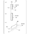
- FIG. 1 It is a photograph which shows an example of a cell culture vessel.
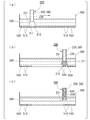
- (A) to (c) are schematic views showing the structure of the cell detachment device according to one embodiment.
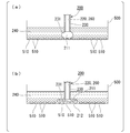
- FIG. (c) are schematic diagrams illustrating an example of a method of exfoliating cells (cell manipulation method).
- FIG. 1 are schematic views explaining an example of the method of exfoliating cells.
- FIG. 1 are schematic views explaining an example of the method of exfoliating cells.
- FIG. 1 and (b) are schematic views explaining an example of the method of exfoliating cells.
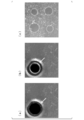
- (A) to (e) are micrographs of the flow path of the cell culture vessel in Experimental Example 1.
- (A) to (c) are micrographs of the state of the cell detachment experiment in Experimental Example 2.
- (A) to (c) are micrographs of the state of the cell detachment experiment in Experimental Example 3.
- the present invention comprises a step of culturing cells in a liquid, a step of arranging a flow path into which a gas can be introduced in the liquid, and a step of forming bubbles at the end of the flow path.
- a cell manipulation method including a step of attaching the cell to the bubble.
- the method of the present embodiment comprises contacting an adherent cell cultured on the surface of a solid phase with a gas-liquid interface and moving the interface along the surface. It can also be said that it is a method of peeling from the solid phase.
- the adherent cells can be exfoliated from the solid phase by the method of the present embodiment without using a proteolytic enzyme or the like.
- the adherent cell means a cell adhered to a solid phase.
- the floating cells are originally cultured in a floating state, they are treated as adherent cells when they are cultured under the condition of adhering to a solid phase.
- the gas is not particularly limited, and examples thereof include air and nitrogen.
- the gas may be sterilized.
- the method for sterilizing the gas is not particularly limited, and examples thereof include passing through a filter having a pore size of about 0.22 ⁇ m or less.
- a filter having a pore size of about 0.22 ⁇ m or less.
- the liquid a cell medium, a buffer solution, or the like is used.
- the interface between the gas and the liquid is not particularly limited as long as it is the surface in which the gas and the liquid are in contact with each other. It can be the interface between liquid and gas, the interface between liquid and gas when the liquid is flowed after flowing the gas through the fluid device, and the like.
- FIG. 1 is a photograph showing an example of a cell culture container.
- the solid phase forms a channel, and the medium can be supplied to the channel to culture the adherent cells on the surface of the solid phase.
- the flow path is provided with an inlet and an outlet. Medium, cells, gas, etc. can be introduced from the inlet and discharged from the outlet.
- the gas is introduced from the introduction port of the cell culture vessel illustrated in FIG. 1 and flowed toward the discharge port, so that the interface between the gas and the medium becomes adherent cells. Since they come into contact with each other and move along the surface of the flow path, the adherent cells cultured on the surface of the flow path of the cell culture vessel can be peeled off.
- the gas needs to be introduced into the cells on the surface of the flow path in such an amount that the interface between the gas and the liquid comes into contact with each other.
- the gas may be continuously introduced from the introduction port of the flow path, or the gas is introduced from the introduction port of the flow path to form bubbles and then the introduction port of the flow path.
- a liquid or gas may be further introduced from the above, and the bubbles may be moved toward the discharge port.
- the liquid may be a cell medium, a buffer solution, or the like.
- the solid phase refers to a surface on which adherent cells can be adhered and cultured, and is a component of one or more extracellular matrix selected from glass; resin such as polystyrene; metal; collagen, fibronectin, laminin, polylysine and the like. Coated surface; Examples thereof include, but are not limited to, a surface coated with various polymers (for example, a polymer whose hydrophilicity and adsorption to cells can be controlled).
- the present invention is disposed in a liquid, comprising a flow path capable of introducing a gas into the liquid, capable of forming the bubbles at the end of the flow path, and culturing in the liquid.
- a cell manipulation device that detaches cells and attaches them to bubbles.
- the cell manipulation device of the present embodiment can also be said to be a cell detachment device provided with a tubular portion capable of generating air bubbles at the end when the end is arranged in a liquid.
- the cell detachment device of the present embodiment is configured so that the bubbles can contact the adherent cells cultured on the surface of the solid phase.
- the cell detachment device 200 has a tubular portion 230 including a flow path 220 through which the gas 210 flows, and by introducing or discharging the gas 210 into the flow path 220.
- the bubbles 211 can be generated in the end 231.
- the cell detachment device 200 shown in FIG. 2A is connected to a control unit 250 that manually or automatically controls the volume of the bubbles 211 by controlling the amount of gas 210 introduced or discharged into the flow path 220. It constitutes a cell detachment system. Therefore, the volume of the bubble 211 can be controlled.
- the cell detachment device 200 can manually or automatically change the distance of the end portion 231 from the solid phase or the cell, and can move the end portion 231 along the surface of the solid phase.
- the control unit 250 may be composed of, for example, a syringe, a pump, or the like.
- the flow path 220 is the lumen of the tubular portion 230.
- FIG. 2B is a cross-sectional view taken along the line bb'of the tubular portion 230 shown in FIG. 2A.
- the tubular portion 230 of the cell detachment device 200 includes a flow path 220 having a circular cross section in a plane perpendicular to the axial direction of the tubular portion.
- the opening area at the end 231 of the flow path 220 is not particularly limited as long as the cells can be detached, but can be, for example, an area larger than the adhesion area of one cell.
- the shape of the tip of the flow path 220 is not particularly limited, and the inner diameter of the flow path 220 may be the same up to the tip, may be gradually increased toward the tip, or may be gradually decreased toward the tip.
- the end surface may be a surface perpendicular to the axis of the flow path 220, or may be a surface not perpendicular to the axis of the flow path 220.
- the flow path 220 can be used for collecting cells, but the tubular portion 230 may further include a second flow path for collecting the detached cells.
- FIG. 3A the tubular portion 230 of the cell detachment device 300 has a double structure of an outer cylinder 221 and an inner cylinder 261.
- the gas 210 is between the outer cylinder 221 and the inner cylinder 261. Is a first flow path 220 through which gas flows, and the inside of the inner cylinder 261 is a second flow path 260 for collecting detached cells.
- the cell detachment device 300 arranges the bubbles 211 in the end 231 when the end 231 of the tubular portion 230 is arranged in the liquid 240 by introducing or discharging the gas 210 into the first flow path 220.
- control unit P 1 which controls the volume of the bubble 211, may constitute a cell detachment system.
- the control unit P 1 includes, for example, a pump.
- cell detachment device 300 may be connected to the control unit P 2 for controlling the flow of liquid in the second flow path 260.
- FIG. 3B is a cross-sectional view taken along the line bb'of the tubular portion 230 shown in FIG. 3A.
- the tubular portion 230 of the cell detachment device 300 has a first flow path 220 having a donut-shaped cross section and a second flow path 260 surrounded by the first flow path 220. And have.
- the gas 210 is introduced or discharged into the first flow path 220, and the cells exfoliated in the second flow path 260 are collected.
- the gas 210 is introduced or discharged into the second flow path 260. It may be drained and the cells collected in the first channel 220.
- the cell detachment device 300 has an independent first flow path 220 for flowing a gas 210 to form bubbles and a second flow path 260 for collecting cells. Mainly different in.
- the shape of the bubble 211 arranged at the end 231 of the tubular portion 230 of the cell detachment device 300 is a donut shape. According to the cell detachment device 300, since the first flow path 220 and the second flow path 260 are independent, the cells are detached by the bubbles 211 arranged at the end 231 of the first flow path 220. , The detached cells can be recovered through the second flow path 260.
- (Modification 2) 4 (a) to 4 (c) are schematic views showing the structure of the cell detachment device according to the embodiment.
- the cell detachment device 400 has a tubular portion 230 having a flow path 220 through which the gas 210 flows, and a tubular portion 230 by introducing or discharging the gas 210 into the flow path 220.
- the control unit P 1 which controls the volume of the bubble 211 is disposed or bubbles 211 may constitute a cell detachment system .
- the control unit P 1 includes, for example, a pump.
- the flow path 220 also serves as a flow path for collecting cells.
- FIG. 4B is a cross-sectional view taken along the line bb'of the tubular portion 230 shown in FIG. 4A.
- the tubular portion 230 of the cell detachment device 400 is mainly different in cross-sectional shape in the plane perpendicular to the axial direction of the tubular portion 230 as compared with the cell detachment device 200 described above.
- FIG. 4C is a perspective view showing a state in which the bubbles 211 are arranged at the end 231 of the tubular portion 230 of the cell detachment device 400.
- the bubble 211 formed at the end 231 of the tubular portion 230 of the cell detachment device 400 is long in one direction. Therefore, it is easy to exfoliate a wider range of adherent cells.
- the adherent cells can be efficiently detached.
- the flow path 220 also serves as a flow path for collecting cells, but the flow path 220 and the cell recovery flow path 260 may be independent.
- the cell recovery flow path 260 may be arranged inside the flow path 220, the flow path 220 may be arranged inside the cell recovery flow path 260, or the flow path 220 may be arranged.
- the cell recovery channel 260 have the same shape and may be arranged adjacent to each other.
- the method for exfoliating the cells according to the second embodiment includes bringing the gas-liquid interface into contact with the adherent cells cultured on the surface of the solid phase, and moving the interface along the surface. .. Then, the interface between the gas and the liquid is brought into contact with the adherent cells by bringing the bubbles generated at the end of the tubular portion of the cell detaching device provided with the tubular portion into contact with the adherent cells. Also, moving the interface along the surface is done by moving the bubbles along the surface of the solid phase.
- FIG. 5A shows a state in which adherent cells 510 are cultured on the surface of the culture vessel 500.
- Adherent cells 510 are cultured in medium (liquid) 240.
- the gas 210 is introduced into the flow path 220 of the cell detachment device 200, and the bubbles 211 are arranged at the end 231 of the tubular portion 230. Then, the bubbles 211 are brought into contact with the adherent cells 510. As a result, the interface 212 between the gas 210 and the liquid 240 (around the contact surface between the bubble 211 and the culture vessel 500) comes into contact with the adherent cells 510.
- FIG. 5A shows the moving direction of the cell detachment device 200 with arrows.
- the direction along the surface of the solid phase is not particularly limited as long as it is parallel to the surface of the solid phase, and may be any direction.
- the adherent cells 510 can be detached from the culture vessel 500 by the above operation.
- FIG. 5B is a schematic view showing a state in which the adherent cells 510 are detached. If the cell detachment device 200 is moved in a line drawing manner, the adherent cells 510 can be detached in a line shape. Further, by changing the size of the bubbles 211, the adherent cells 510 can be detached in a line shape having a desired thickness. Furthermore, as shown in FIG. 5B, the inventors have found that the detached adherent cells 510 adhere to the surface of the bubble 211.
- the cells 510 attached to the surface of the bubble 211 may be recovered by sucking the gas 210 in the flow path 220.
- cells can be selectively detached by a device having a simple structure, and can be further recovered.
- FIG. 6A is a top view showing a state in which adherent cells 510 are cultured on the surface of the culture vessel 500.
- Adherent cells 510 are cultured in medium (liquid) 240.
- the gas 210 is introduced into the flow path 220 of the cell detachment device 400, and the bubbles 211 are arranged at the end 231 of the tubular portion 230. Then, the bubbles 211 are brought into contact with the adherent cells 510. As a result, the interface 212 between the gas 210 and the liquid 240 comes into contact with the adherent cells 510.
- FIG. 6A shows the moving direction of the cell detachment device 200 with arrows.
- the direction along the surface of the solid phase is not particularly limited as long as it is parallel to the surface of the solid phase, and may be any direction.
- FIG. 6B is a schematic view showing a state in which the adherent cells 510 are detached. After that, the detached adherent cells 510 may be collected through the flow path 260.
- the method of the second embodiment has been described above by taking the case of using the cell detachment devices 200 and 400 as an example.
- a cell detachment device other than the cell detachment devices 200 and 400 may be used as the cell detachment device.
- Examples of the cell detachment device other than the cell detachment devices 200 and 400 include, but are not limited to, the above-mentioned cell detachment device 300 and the like.
- the method for exfoliating the cells according to the third embodiment is to bring the gas-liquid interface into contact with the adherent cells cultured on the surface of the solid phase, and to move the interface in a direction along the surface. including. Then, the interface between the gas and the liquid is brought into contact with the adherent cells by contacting the adherent cells with the bubbles of the above-mentioned cell detachment device in which the bubbles are arranged at the ends. Also, moving the interface along the surface is performed by changing the volume of bubbles in the cell detachment device.
- FIG. 7A shows a state in which adherent cells 510 are cultured on the surface of the culture vessel 500.
- Adherent cells 510 are cultured in medium (liquid) 240.
- the gas 210 is introduced into the flow path 220 of the cell detachment device 200, and the bubbles 211 are arranged at the end 231 of the tubular portion 230. Then, the bubbles 211 are brought into contact with the adherent cells 510. As a result, the interface 212 between the gas 210 and the liquid 240 comes into contact with the adherent cells 510.
- the volume of the bubble 211 of the cell detachment device 200 is changed. Specifically, as shown in FIG. 7B, the gas 210 is introduced into the flow path 220 to increase the volume of the bubbles 211.
- the gas-liquid interface 212 (around the contact surface between the bubble 211 and the culture vessel 500) moves in the direction along the surface of the culture vessel. That is, the surface of the bubbles moves in all directions around the adherent cells 510 that existed directly under the flow path 220.
- the adherent cells 510 can also be detached from the culture vessel 500 by the above operation. Further, as shown in FIG. 7B, the inventors have found that the detached adherent cells 510 adhere to the surface of the bubble 211.
- the cells 510 attached to the surface of the bubble 211 may be recovered by sucking the gas 210 in the flow path 220.
- the method of the third embodiment has been described above by taking the case of using the cell detachment device 200 as an example.
- a cell detachment device other than the cell detachment device 200 may be used as the cell detachment device.
- Examples of the cell detachment device other than the cell detachment device 200 include, but are not limited to, the cell detachment device 300 and the cell detachment device 400 described above.
- the method for exfoliating the cells according to the fourth embodiment is to bring the gas-liquid interface into contact with the adherent cells cultured on the surface of the solid phase, and to move the interface in a direction along the surface. including. Then, the interface between the gas and the liquid is brought into contact with the adherent cells by contacting the adherent cells with the bubbles of the above-mentioned cell detachment device in which the bubbles are arranged at the ends. Also, moving the interface along the surface is done by changing the distance between the cell detachment device and the adherent cells.
- FIG. 8A shows a state in which adherent cells 510 are cultured on the surface of the culture vessel 500.
- Adherent cells 510 are cultured in medium (liquid) 240.
- the gas 210 is introduced into the flow path 220 of the cell detachment device 200, and the bubbles 211 are arranged at the end 231 of the tubular portion 230. Then, the bubbles 211 are brought into contact with the adherent cells 510. As a result, the interface 212 between the gas 210 and the liquid 240 comes into contact with the adherent cells 510.
- the distance between the cell detachment device and the adherent cell is changed. Specifically, as shown in FIG. 8B, the tubular portion 230 is brought close to the surface of the culture vessel. As a result, the bubble 211 is deformed.
- the gas-liquid interface 212 (around the contact surface between the bubble 211 and the culture vessel 500) moves in the direction along the surface of the culture vessel. That is, the surface of the bubbles moves in all directions around the adherent cells 510 that existed directly under the flow path 220.
- the adherent cells 510 can also be detached from the culture vessel 500 by the above operation. Further, as shown in FIG. 8B, the inventors have found that the detached adherent cells 510 adhere to the surface of the bubble 211.
- the cells 510 attached to the surface of the bubble 211 may be recovered by sucking the gas 210 in the flow path 220.
- the method of the fourth embodiment has been described above by taking the case of using the cell detachment device 200 as an example.
- a cell detachment device other than the cell detachment device 200 may be used as the cell detachment device.
- Examples of the cell detachment device other than the cell detachment device 200 include, but are not limited to, the cell detachment device 300 and the cell detachment device 400 described above.
- the technique of exfoliating the adherent cells adhered to the solid phase has been described, but the embodiments of the present invention are not limited thereto.
- the detached adherent cells adhere to the surface of the cells by contacting with the cells, but the adhesion of the cells to the surface of the cells can also be applied to the suspended cells floating in the culture medium. it can.
- the present invention comprises (i) a cell detachment device comprising a tubular portion capable of generating air bubbles at the end when the end is placed in a liquid, and (ii) said cell detachment.
- a cell exfoliation system including a control unit that controls the generation of the bubbles by introducing or discharging the gas into the tubular portion of the device.
- the control unit is the same as that described above, and may be composed of, for example, a syringe, a pump, a CPU that controls these, and the like.
- the present invention provides a fluid device system comprising a fluid device in which a solid phase capable of culturing adherent cells on the surface is arranged in a flow path, and the cell detachment system described above.
- the fluid device system of the present embodiment allows adherent cells to be cultured and further exfoliated. The detached cells can also be recovered.
- the cell detachment device, the cell detachment system, and the fluid device system are devices having a simple structure, and can selectively detach and collect cells. Therefore, for example, when the target cells are cultured on the feeder cells, it can be used to remove only unnecessary feeder cells, and can be applied to regenerative medicine. It is also useful in a scratch assay to evaluate the rate of cell migration to the exfoliated and recovered portion of cells.
- FIG. 1 A cell culture vessel shown in FIG. 1 was prepared. Specifically, on a glass substrate, a first polydimethylsiloxane (PDMS) sheet having a thickness of 0.1 mm, a first acrylic plate having a thickness of 2 mm, a second PDMS sheet having a thickness of 0.1 mm, and a thickness. A second acrylic plate having a size of 2 mm was laminated in this order to prepare a cell culture container.
- PDMS polydimethylsiloxane
- the first and second PDMS sheets and the first acrylic plate were laminated by hollowing out a flow path pattern having the shape shown in FIG. 1 using a laser processing machine (model "VLS 2.30", Yokohama Systems Co., Ltd.). Further, the second acrylic plate was laminated by forming holes serving as an introduction port and an discharge port. Subsequently, the adapter shown in FIG. 1 was attached to the introduction port and the discharge port to obtain a cell culture container.
- ⁇ Cell culture The cells were cultured in the flow path of the prepared cell culture vessel. As cells, Kato III cells, which are human gastric cancer cell lines, were used.
- FIG. 9A is a photograph of the flow path before introducing air.
- FIG. 9B is a photograph of a state in which air is flowing into the observation area of the flow path.
- FIG. 9C is a photograph of a state in which the observation area of the flow path is completely filled with air.
- FIG. 9D is a photograph of a state in which air is flowing out from the observation area of the flow path.
- FIG. 9E is a photograph of a state in which the observation area of the flow path is filled with the medium again.
- HeLa cells which are cell lines derived from human cervical cancer, were used. After culturing the cells until they became confluent, a detachment experiment was performed.
- 10 (a) to 10 (c) are micrographs of a cell detachment experiment. The magnification is 4 times.
- FIG. 10A the end of the cell detachment device was brought close to the cell.
- the arrow points to the end of the cell detachment device.
- FIG. 10B air bubbles were formed at the ends of the cell detachment device to bring them into contact with the cells, and the cell detachment device was moved in a direction parallel to the bottom surface of the cell culture dish. ..
- the arrow points to the end of the cell detachment device.
- FIG. 10 (c) is a photograph of the state after the cells have been detached.
- the portion surrounded by the dotted line indicates the region where the cells have detached. It can be seen that the cells were detached in a line as the bubbles moved. The result is that the adherent cells cultured on the surface of the solid phase are brought into contact with the interface between gas and liquid, and then the interface is moved along the surface to detach the adherent cells from the solid phase. It further supports what can be done.
- HeLa cells which are cell lines derived from human cervical cancer, were used. After culturing the cells until they became confluent, a detachment experiment was performed.
- FIGS. 11 (a) to 11 (c) are photomicrographs of a cell detachment experiment. The magnification is 4 times. First, as shown in FIG. 11A, the end of the cell detachment device was brought close to the cell. In FIG. 11 (a), the arrow points to the end of the cell detachment device.
- FIG. 11B bubbles were formed at the end of the cell detachment device, the amount of air introduced into the flow path of the cell detachment device was increased, and the volume of the bubbles was increased.
- the arrow points to the end of the cell detachment device. The same operation was performed four times. Moreover, the volume of the bubble was changed every time.
- FIG. 11 (c) is a photograph of the state after the cells have been detached.
- the portion surrounded by the dotted line indicates the region where the cells have detached.
- the cells in the substantially circular region that passed around the bubble were detached. It was clarified that the area where cells exfoliate can be controlled by changing the volume of bubbles. The result is that the adherent cells cultured on the surface of the solid phase are brought into contact with the interface between gas and liquid, and then the interface is moved along the surface to detach the adherent cells from the solid phase. It further supports what can be done.
- Cell detachment device cell manipulation device
- 210 ... Gas
- 211 ... Bubbles
- 212 ... Interface
- 220 ... Flow path (first flow path), 221 ... Outer cylinder, 230 ... Cylindrical part, 231 ... end, 240 ... liquid, 250, P 1 , P 2 ... control unit, 260 ... second flow path, 261 ... inner cylinder, 500 ... culture vessel, 510 ... adherent cells.
Landscapes
- Life Sciences & Earth Sciences (AREA)
- Health & Medical Sciences (AREA)
- Engineering & Computer Science (AREA)
- Chemical & Material Sciences (AREA)
- Wood Science & Technology (AREA)
- Organic Chemistry (AREA)
- Biotechnology (AREA)
- Genetics & Genomics (AREA)
- Bioinformatics & Cheminformatics (AREA)
- Zoology (AREA)
- Biomedical Technology (AREA)
- Biochemistry (AREA)
- General Health & Medical Sciences (AREA)
- Microbiology (AREA)
- General Engineering & Computer Science (AREA)
- Cell Biology (AREA)
- Analytical Chemistry (AREA)
- Immunology (AREA)
- Hydrology & Water Resources (AREA)
- Physics & Mathematics (AREA)
- Pathology (AREA)
- General Physics & Mathematics (AREA)
- Sustainable Development (AREA)
- Mechanical Engineering (AREA)
- Medicinal Chemistry (AREA)
- Tropical Medicine & Parasitology (AREA)
- Virology (AREA)
- Clinical Laboratory Science (AREA)
- Chemical Kinetics & Catalysis (AREA)
- Apparatus Associated With Microorganisms And Enzymes (AREA)
- Micro-Organisms Or Cultivation Processes Thereof (AREA)
Priority Applications (7)
| Application Number | Priority Date | Filing Date | Title |
|---|---|---|---|
| US17/593,544 US12504353B2 (en) | 2019-03-25 | 2020-03-25 | Cell manipulation device and cell manipulation method |
| JP2021509515A JP7331921B2 (ja) | 2019-03-25 | 2020-03-25 | 細胞操作システム及び細胞操作方法 |
| CN202080032753.4A CN113785044A (zh) | 2019-03-25 | 2020-03-25 | 细胞操作装置及细胞操作方法 |
| EP20777867.1A EP3950920A4 (en) | 2019-03-25 | 2020-03-25 | Cell manipulation device and cell manipulation method |
| JP2023131499A JP7643495B2 (ja) | 2019-03-25 | 2023-08-10 | 生物体操作装置及び生物体操作方法 |
| JP2025028725A JP2025074131A (ja) | 2019-03-25 | 2025-02-26 | 細胞操作方法 |
| US19/404,532 US20260086001A1 (en) | 2019-03-25 | 2025-12-01 | Cell manipulation device and cell manipulation method |
Applications Claiming Priority (2)
| Application Number | Priority Date | Filing Date | Title |
|---|---|---|---|
| JP2019-055986 | 2019-03-25 | ||
| JP2019055986 | 2019-03-25 |
Related Child Applications (2)
| Application Number | Title | Priority Date | Filing Date |
|---|---|---|---|
| US17/593,544 A-371-Of-International US12504353B2 (en) | 2019-03-25 | 2020-03-25 | Cell manipulation device and cell manipulation method |
| US19/404,532 Continuation US20260086001A1 (en) | 2019-03-25 | 2025-12-01 | Cell manipulation device and cell manipulation method |
Publications (1)
| Publication Number | Publication Date |
|---|---|
| WO2020196635A1 true WO2020196635A1 (ja) | 2020-10-01 |
Family
ID=72610018
Family Applications (1)
| Application Number | Title | Priority Date | Filing Date |
|---|---|---|---|
| PCT/JP2020/013367 Ceased WO2020196635A1 (ja) | 2019-03-25 | 2020-03-25 | 細胞操作デバイス及び細胞操作方法 |
Country Status (5)
| Country | Link |
|---|---|
| US (2) | US12504353B2 (https=) |
| EP (1) | EP3950920A4 (https=) |
| JP (3) | JP7331921B2 (https=) |
| CN (1) | CN113785044A (https=) |
| WO (1) | WO2020196635A1 (https=) |
Cited By (3)
| Publication number | Priority date | Publication date | Assignee | Title |
|---|---|---|---|---|
| WO2022065458A1 (ja) * | 2020-09-24 | 2022-03-31 | 株式会社ニコン | 生物体に力を加える方法および生物体加力装置 |
| WO2022065459A1 (ja) * | 2020-09-24 | 2022-03-31 | 株式会社ニコン | 生物体操作方法および生物体操作装置 |
| JPWO2022065460A1 (https=) * | 2020-09-24 | 2022-03-31 |
Families Citing this family (1)
| Publication number | Priority date | Publication date | Assignee | Title |
|---|---|---|---|---|
| EP4219673A4 (en) * | 2020-09-24 | 2025-05-07 | Nikon Corporation | METHOD FOR MANIPULATING AN ORGANISM AND DEVICE FOR MANIPULATING AN ORGANISM |
Citations (5)
| Publication number | Priority date | Publication date | Assignee | Title |
|---|---|---|---|---|
| JPH0350900U (https=) * | 1989-09-21 | 1991-05-17 | ||
| WO2015098919A1 (ja) * | 2013-12-27 | 2015-07-02 | 積水化学工業株式会社 | 細胞の剥離方法、細胞支持用基材、並びに、細胞の培養方法 |
| JP2017112923A (ja) | 2015-12-25 | 2017-06-29 | 株式会社Screenホールディングス | 細胞剥離装置および細胞剥離方法 |
| US20180298318A1 (en) * | 2015-12-30 | 2018-10-18 | Berkeley Lights, Inc. | Microfluidic Devices for Optically-Driven Convection and Displacement, Kits and Methods Thereof |
| JP2019055986A (ja) | 2013-03-07 | 2019-04-11 | エフ.ホフマン−ラ ロシュ アーゲーF. Hoffmann−La Roche Aktiengesellschaft | 新規ピラゾール誘導体 |
Family Cites Families (6)
| Publication number | Priority date | Publication date | Assignee | Title |
|---|---|---|---|---|
| JP2010172231A (ja) * | 2009-01-28 | 2010-08-12 | Olympus Corp | 細胞またはコロニーの採取装置及び細胞またはコロニーの採取方法 |
| JP5549209B2 (ja) | 2009-12-11 | 2014-07-16 | 株式会社Ihi | 付着性細胞培養装置 |
| WO2012002497A1 (ja) * | 2010-07-01 | 2012-01-05 | 株式会社カネカ | 細胞培養用ディスポセット、細胞培養装置及び細胞調製方法 |
| CN102985526A (zh) * | 2010-07-16 | 2013-03-20 | 株式会社日立制作所 | 细胞培养容器及细胞培养装置 |
| JP5722329B2 (ja) * | 2010-08-12 | 2015-05-20 | 株式会社日立製作所 | 自動培養装置 |
| CN118562610A (zh) | 2013-06-24 | 2024-08-30 | 威尔逊沃夫制造公司 | 用于透气性细胞培养过程的封闭系统装置和方法 |
-
2020
- 2020-03-25 US US17/593,544 patent/US12504353B2/en active Active
- 2020-03-25 CN CN202080032753.4A patent/CN113785044A/zh active Pending
- 2020-03-25 JP JP2021509515A patent/JP7331921B2/ja active Active
- 2020-03-25 EP EP20777867.1A patent/EP3950920A4/en active Pending
- 2020-03-25 WO PCT/JP2020/013367 patent/WO2020196635A1/ja not_active Ceased
-
2023
- 2023-08-10 JP JP2023131499A patent/JP7643495B2/ja active Active
-
2025
- 2025-02-26 JP JP2025028725A patent/JP2025074131A/ja active Pending
- 2025-12-01 US US19/404,532 patent/US20260086001A1/en active Pending
Patent Citations (5)
| Publication number | Priority date | Publication date | Assignee | Title |
|---|---|---|---|---|
| JPH0350900U (https=) * | 1989-09-21 | 1991-05-17 | ||
| JP2019055986A (ja) | 2013-03-07 | 2019-04-11 | エフ.ホフマン−ラ ロシュ アーゲーF. Hoffmann−La Roche Aktiengesellschaft | 新規ピラゾール誘導体 |
| WO2015098919A1 (ja) * | 2013-12-27 | 2015-07-02 | 積水化学工業株式会社 | 細胞の剥離方法、細胞支持用基材、並びに、細胞の培養方法 |
| JP2017112923A (ja) | 2015-12-25 | 2017-06-29 | 株式会社Screenホールディングス | 細胞剥離装置および細胞剥離方法 |
| US20180298318A1 (en) * | 2015-12-30 | 2018-10-18 | Berkeley Lights, Inc. | Microfluidic Devices for Optically-Driven Convection and Displacement, Kits and Methods Thereof |
Cited By (3)
| Publication number | Priority date | Publication date | Assignee | Title |
|---|---|---|---|---|
| WO2022065458A1 (ja) * | 2020-09-24 | 2022-03-31 | 株式会社ニコン | 生物体に力を加える方法および生物体加力装置 |
| WO2022065459A1 (ja) * | 2020-09-24 | 2022-03-31 | 株式会社ニコン | 生物体操作方法および生物体操作装置 |
| JPWO2022065460A1 (https=) * | 2020-09-24 | 2022-03-31 |
Also Published As
| Publication number | Publication date |
|---|---|
| JP2023138839A (ja) | 2023-10-02 |
| JP2025074131A (ja) | 2025-05-13 |
| CN113785044A (zh) | 2021-12-10 |
| JPWO2020196635A1 (https=) | 2020-10-01 |
| US20260086001A1 (en) | 2026-03-26 |
| EP3950920A4 (en) | 2023-02-01 |
| EP3950920A1 (en) | 2022-02-09 |
| JP7331921B2 (ja) | 2023-08-23 |
| JP7643495B2 (ja) | 2025-03-11 |
| US20220170826A1 (en) | 2022-06-02 |
| US12504353B2 (en) | 2025-12-23 |
Similar Documents
| Publication | Publication Date | Title |
|---|---|---|
| JP7643495B2 (ja) | 生物体操作装置及び生物体操作方法 | |
| US8114646B2 (en) | Method for ultrasonic cell removal | |
| JP4507845B2 (ja) | 細胞培養容器、及び培養細胞 | |
| JP7019601B2 (ja) | 高密度細胞増殖と代謝産物交換のための基材 | |
| US10351811B2 (en) | Cell culture container | |
| CN117264765A (zh) | 细胞捕获与肿瘤球培养的阵列化芯片及其制备和操作方法 | |
| CN108779422A (zh) | 细胞培养用容器及其使用方法 | |
| JP2010011747A (ja) | 細胞培養容器および細胞培養方法 | |
| Huang et al. | Embryo formation from low sperm concentration by using dielectrophoretic force | |
| JP2008259445A (ja) | 細胞分離装置 | |
| JP4649224B2 (ja) | 付着性細胞の培養方法および培養装置 | |
| JP5828823B2 (ja) | 細胞培養モジュール及び細胞培養方法 | |
| JP6169869B2 (ja) | 細胞培養容器 | |
| Choi et al. | Development of an air-knife system for highly reproducible fabrication of polydimethylsiloxane microstencils | |
| Price et al. | Subtractive methods for forming microfluidic gels of extracellular matrix proteins | |
| CN112608848B (zh) | 一种适用于太空环境的细胞悬浮培养单元 | |
| JP4967520B2 (ja) | 細胞転写用部材 | |
| JP5943456B2 (ja) | 生物学的対象物の分化制御方法及びその装置 | |
| JP2006050975A (ja) | 細胞操作用基板およびそれを用いる灌流培養装置 | |
| Kaji et al. | Stepwise formation of patterned cell co‐cultures in silicone tubing | |
| JP2017046591A (ja) | 細胞培養システムおよび細胞の剥離方法 | |
| JP2016000008A (ja) | 接着細胞の培養装置および培養方法 | |
| CN117535150B (zh) | 一种2d微型培养芯片及其制备方法与应用 | |
| US20250186659A1 (en) | Fabrication method of directional tissue with acoustic patterning of pore- forming particles | |
| Yahya | 3-Dimensional Carbon Micro-Electro Mechanical System (MEMS) Electrode for Potential Dielectrophoretic Hepatic Cell Patterning Application |
Legal Events
| Date | Code | Title | Description |
|---|---|---|---|
| 121 | Ep: the epo has been informed by wipo that ep was designated in this application |
Ref document number: 20777867 Country of ref document: EP Kind code of ref document: A1 |
|
| ENP | Entry into the national phase |
Ref document number: 2021509515 Country of ref document: JP Kind code of ref document: A |
|
| NENP | Non-entry into the national phase |
Ref country code: DE |
|
| ENP | Entry into the national phase |
Ref document number: 2020777867 Country of ref document: EP Effective date: 20211025 |