WO2020196558A1 - 操作装置 - Google Patents
操作装置 Download PDFInfo
- Publication number
- WO2020196558A1 WO2020196558A1 PCT/JP2020/013155 JP2020013155W WO2020196558A1 WO 2020196558 A1 WO2020196558 A1 WO 2020196558A1 JP 2020013155 W JP2020013155 W JP 2020013155W WO 2020196558 A1 WO2020196558 A1 WO 2020196558A1
- Authority
- WO
- WIPO (PCT)
- Prior art keywords
- user
- control unit
- operating environment
- operating
- operating device
- Prior art date
- Legal status (The legal status is an assumption and is not a legal conclusion. Google has not performed a legal analysis and makes no representation as to the accuracy of the status listed.)
- Ceased
Links
Images







Classifications
-
- B—PERFORMING OPERATIONS; TRANSPORTING
- B60—VEHICLES IN GENERAL
- B60R—VEHICLES, VEHICLE FITTINGS, OR VEHICLE PARTS, NOT OTHERWISE PROVIDED FOR
- B60R16/00—Electric or fluid circuits specially adapted for vehicles and not otherwise provided for; Arrangement of elements of electric or fluid circuits specially adapted for vehicles and not otherwise provided for
- B60R16/02—Electric or fluid circuits specially adapted for vehicles and not otherwise provided for; Arrangement of elements of electric or fluid circuits specially adapted for vehicles and not otherwise provided for electric constitutive elements
-
- B—PERFORMING OPERATIONS; TRANSPORTING
- B60—VEHICLES IN GENERAL
- B60R—VEHICLES, VEHICLE FITTINGS, OR VEHICLE PARTS, NOT OTHERWISE PROVIDED FOR
- B60R16/00—Electric or fluid circuits specially adapted for vehicles and not otherwise provided for; Arrangement of elements of electric or fluid circuits specially adapted for vehicles and not otherwise provided for
- B60R16/02—Electric or fluid circuits specially adapted for vehicles and not otherwise provided for; Arrangement of elements of electric or fluid circuits specially adapted for vehicles and not otherwise provided for electric constitutive elements
- B60R16/023—Electric or fluid circuits specially adapted for vehicles and not otherwise provided for; Arrangement of elements of electric or fluid circuits specially adapted for vehicles and not otherwise provided for electric constitutive elements for transmission of signals between vehicle parts or subsystems
- B60R16/027—Electric or fluid circuits specially adapted for vehicles and not otherwise provided for; Arrangement of elements of electric or fluid circuits specially adapted for vehicles and not otherwise provided for electric constitutive elements for transmission of signals between vehicle parts or subsystems between relatively movable parts of the vehicle, e.g. between steering wheel and column
-
- G—PHYSICS
- G06—COMPUTING OR CALCULATING; COUNTING
- G06F—ELECTRIC DIGITAL DATA PROCESSING
- G06F3/00—Input arrangements for transferring data to be processed into a form capable of being handled by the computer; Output arrangements for transferring data from processing unit to output unit, e.g. interface arrangements
- G06F3/01—Input arrangements or combined input and output arrangements for interaction between user and computer
- G06F3/048—Interaction techniques based on graphical user interfaces [GUI]
- G06F3/0481—Interaction techniques based on graphical user interfaces [GUI] based on specific properties of the displayed interaction object or a metaphor-based environment, e.g. interaction with desktop elements like windows or icons, or assisted by a cursor's changing behaviour or appearance
- G06F3/0482—Interaction with lists of selectable items, e.g. menus
-
- G—PHYSICS
- G06—COMPUTING OR CALCULATING; COUNTING
- G06F—ELECTRIC DIGITAL DATA PROCESSING
- G06F3/00—Input arrangements for transferring data to be processed into a form capable of being handled by the computer; Output arrangements for transferring data from processing unit to output unit, e.g. interface arrangements
- G06F3/01—Input arrangements or combined input and output arrangements for interaction between user and computer
- G06F3/048—Interaction techniques based on graphical user interfaces [GUI]
- G06F3/0487—Interaction techniques based on graphical user interfaces [GUI] using specific features provided by the input device, e.g. functions controlled by the rotation of a mouse with dual sensing arrangements, or of the nature of the input device, e.g. tap gestures based on pressure sensed by a digitiser
- G06F3/0488—Interaction techniques based on graphical user interfaces [GUI] using specific features provided by the input device, e.g. functions controlled by the rotation of a mouse with dual sensing arrangements, or of the nature of the input device, e.g. tap gestures based on pressure sensed by a digitiser using a touch-screen or digitiser, e.g. input of commands through traced gestures
Definitions
- the present invention relates to an operating device.
- Patent Document 1 An input device provided in a vehicle and displaying an input content operated by a driver on a display unit provided in the vehicle is known (see, for example, Patent Document 1).
- This input device includes a touch pad provided on the steering wheel of the vehicle.
- An object of the present invention is to provide an operating device capable of configuring an operating environment suitable for a user's characteristics.
- An operation device includes an operation unit that is arranged in a vehicle and accepts an operation performed on an operation surface, and at least a display screen configuration and an operation method for the operation unit according to the characteristics of a user. It has a control unit that constitutes an environment.
- an operating device that constitutes an operating environment suitable for the characteristics of the user.
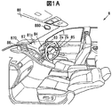
- FIG. 1A is an explanatory view showing the inside of the vehicle according to the embodiment.
- FIG. 1B is a block diagram of the control system of the operating device according to the embodiment.
- FIG. 2A is an explanatory diagram showing a display screen of the display device according to the embodiment.
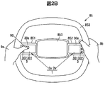
- FIG. 2B is an explanatory view showing the steering according to the embodiment.
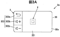
- FIG. 3A is an explanatory view showing the left touch pad unit according to the embodiment.
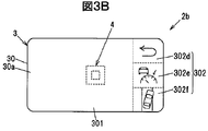
- FIG. 3B is an explanatory view showing a touch pad unit on the right side according to the embodiment.
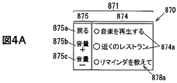
- FIG. 4A is an explanatory diagram for explaining an operating environment provided by the operating device according to the embodiment to the entry user.
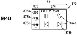
- FIG. 4B is an explanatory diagram for explaining an operating environment provided by the operating device according to the embodiment to the entry user.
- FIG. 4A is an explanatory diagram for explaining an operating environment provided by the operating device according to the embodiment to the entry user.
- FIG. 4C is an explanatory diagram for explaining an operating environment provided by the operating device according to the embodiment to the entry user.
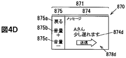
- FIG. 4D is an explanatory diagram for explaining an operating environment provided by the operating device according to the embodiment to the entry user.
- FIG. 5A is an explanatory diagram for explaining an operating environment provided by the operating device according to the embodiment to a senior user.
- FIG. 5B is an explanatory diagram for explaining an operating environment provided by the operating device according to the embodiment to a senior user.
- FIG. 6A is an explanatory diagram for explaining an operating environment provided by the operating device to digital native users.
- FIG. 6B is an explanatory diagram for explaining an operating environment provided by the operating device to digital native users.
- FIG. 6C is an explanatory diagram for explaining an operating environment provided by the operating device to digital native users.
- FIG. 6D is an explanatory diagram for explaining an operating environment provided by the operating device to digital native users.
- FIG. 7A is an explanatory diagram for explaining an operating environment provided by the operating device to the high literacy user.
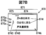
- FIG. 7B is an explanatory diagram for explaining the operating environment provided by the operating device to the high literacy user.
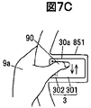
- FIG. 7C is an explanatory diagram for explaining an operating environment provided by the operating device to the high literacy user.
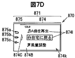
- FIG. 7D is an explanatory diagram for explaining the operating environment provided by the operating device to the high literacy user.
- FIG. 7E is an explanatory diagram for explaining an operating environment provided by the operating device to the high literacy user.
- FIG. 7F is an explanatory diagram for explaining the operating environment provided by the operating device to the high literacy user.
- the operating device constitutes an operating environment including an operating unit that is arranged in the vehicle and accepts operations performed on the operating surface, and at least a display screen configuration and an operating method for the operating unit according to the characteristics of the user. It has a control unit and a control unit.
- the operation device 1 is arranged on the vehicle 8 and receives an operation performed on the operation surface 30a, and at least the configuration and operation unit of the display screen 870 according to the characteristics of the user. It has a control unit 6 that constitutes an operating environment including an operation method for 2.
- the operation device 1 is configured so that, for example, the in-vehicle device of the vehicle 8 can be operated as the operation target device 89.
- the in-vehicle device is, for example, a music and video playback device, a navigation device, an electric seat device, a cruise control device, a lane keeping device, an automatic driving device, a vehicle control device capable of making various settings related to the vehicle 8, and the like. ..
- the vehicle 8 is arranged on the meter display 84 arranged on the meter panel 83, the main display 86 arranged on the center console 81b, and the instrument panel 81c as shown in FIG. 1A, and the projection area of the windshield 88. It is provided with a display device such as a head-up display 87 that projects a display object on the windshield and a room mirror monitor 880 arranged on the windshield 88.
- a display device such as a head-up display 87 that projects a display object on the windshield and a room mirror monitor 880 arranged on the windshield 88.
- GUI Graphical User Interface
- the display screen 870 of the display device 5 includes a menu display area 874 and a menu display area 876, and a direct display area 875 and a direct display area 877.
- the operation unit 2 includes a touch pad unit 2a and a touch pad unit 2b.
- the touch pad unit 2a and the touch pad unit 2b are arranged on the left and right spoke portions (spoke portions 851 and spoke portions 852) of the steering wheel 85, for example, as shown in FIG. 2B.
- the spoke portions 851 and spoke portions 852 connect a base portion 850 on which an alarm, an airbag, or the like is arranged and a ring portion 853 gripped by the user. Further, as shown in FIG. 2B, the spoke portions 851 and the spoke portions 852 extend substantially horizontally at the steering position in a state where the vehicle 8 is traveling straight, and connect the base portion 850 and the ring portion 853.
- the touch pad unit 2a and the touch pad unit 2b can be operated by the user in a state where the ring portion 853, the spoke portion 851, and the spoke portion 852 are gripped by the left hand 9a and the right hand 9b.
- the operating device 1 may be configured to include either the touch pad unit 2a or the touch pad unit 2b.
- the touchpad unit 2a and the touchpad unit 2b each have a touchpad 3 and a switch 4.
- the touch pad 3 of the touch pad unit 2a has a rectangular operation surface 30a.
- the touch pad 3 of the touch pad unit 2b has the same shape as the touch pad 3 of the touch pad unit 2a, as shown in FIG. 3B.
- the shape of the touch pad 3 is not limited to this.
- the touch pad unit 2a will be mainly described.
- the touch pad 3 is configured to detect a touch input, a tracing operation, a flick operation, and the like on the operation surface 30a.
- a touch pad such as a resistive film type or a capacitance type can be used.
- the touch pad 3 of the present embodiment uses a capacitance type touch pad.
- the left and right touch pads 3 output detection information S 1 and detection information S 3 indicating the detection result to the control unit 6.
- the user can make a selection decision (selection decision) by, for example, performing a push operation on the touch pad 3.
- the operation surface 30a of the touch pad 3 is divided into a menu input area 301 and a direct input area 302 by dotted lines on the paper surfaces of FIGS. 3A and 3B, for example.
- the dotted lines shown in FIGS. 3A and 3B are lines attached for explanation and not actually attached lines.
- the dividing line between the menu input area 301 and the direct input area 302 may be formed on the operation surface 30a by printing or the like.
- the mark of the direct input area 302 imitates a function that can be operated, and is provided on the operation surface 30a by printing.
- the touch pad 3 on the right side has an arrangement in which the touch pad 3 on the left side, the menu input area 301, and the direct input area 302 are interchanged. That is, the direct input area 302 is set on the ring portion 853 side of the steering 85, and the menu input area 301 is set on the base 850 side. This is because the direct input area 302 is arranged at a position where touch input is easy while the steering wheel 85 is gripped, and the menu input area 301 is arranged at a position where the operating finger is extended and traced easily.
- the menu input area 301 of the touch pad 3 of the touch pad unit 2a is an area in which the list 874A displayed in the menu display area 874 of the display screen 870 can be scrolled up and down, as shown in FIGS. 2A and 3A. ..
- the menu input area 301 of the touch pad 3 of the touch pad unit 2b is an area in which the list 876A displayed in the menu display area 876 of the display screen 870 can be scrolled up and down as shown in FIGS. 2A and 3B. is there.
- the first touch area 302a to the third touch area 302c are displayed in the direct display area 875 of the display screen 870. It corresponds to the icon 875a to the icon 875c.
- the user can select a desired icon from the icons 875a to 875c by performing touch input in the touch area of the direct input area 302 on the touch pad unit 2a side.
- the icon 875a is assigned a function of returning to the state before the processing when the processing instructed via the touch pad 3 on the left side is performed.
- the icon 875b is assigned a function to raise the volume.
- the icon 875c is assigned a function of lowering the volume.
- the first touch area 302d to the third touch area 302f are displayed in the direct display area 877 of the display screen 870. It corresponds to the icon 877a to the icon 877c.
- the user makes a desired touch input from the icons 877a to 877c by performing touch input to any of the first touch area 302d to the third touch area 302f of the direct input area 302 of the touch pad 3 of the touch pad unit 2b. You can select the icon.
- the icon 877a is assigned a function of returning to the state before the processing when the processing instructed via the touch pad 3 on the right side is performed.
- the icon 877b is assigned an auto-cruise control function, which is a driving assistance function.
- the icon 877c is assigned a lane keep assist function, which is a driving assistance function.
- the control unit 6 sets an absolute coordinate system suitable for touch input with respect to the direct input area 302 of the touch pad 3. Further, the control unit 6 sets a relative coordinate system or an absolute coordinate system with respect to the menu input area 301 according to the display of the display device 5. The control unit 6 sets the relative coordinate system to the menu input area 301 when the trace operation is suitable according to the screen transition, and sets the absolute coordinate system to the menu input area when the touch input is suitable. Set to 301.
- the switch 4 is arranged near the center of the operation surface 30a.
- the switch 4 is a micro switch that detects the push-down of the touch pad 3, that is, the push operation performed on the operation surface 30a.
- the switch 4 is not limited to a mechanical switch such as a micro switch, and may be a non-contact switch using a magnetic sensor or the like, a load sensor that detects a push operation by detecting a load associated with the push operation, or the like. ..
- the switch 4 of the touch pad unit 2a outputs the switch signal S 2 to the control unit 6. Further, the switch 4 of the touch pad unit 2b outputs the switch signal S 4 to the control unit 6.
- the display screen 870 of the head-up display 87 has a left display area 871, a right display area 872, and a center display area 873.
- the left display area 871 is a display area corresponding to the touch pad 3 arranged on the left side of the steering wheel 85.
- the left display area 871 includes a menu display area 874 and a direct display area 875.
- the menu display area 874 is an area for displaying a menu, an icon, a cursor, and the like based on an operation performed on the menu input area 301 of the touch pad unit 2a.
- the direct display area 875 is an area for displaying corresponding to the first touch area 302a to the third touch area 302c of the direct input area 302 of the touchpad unit 2a.
- the right display area 872 is a display area corresponding to the touch pad 3 arranged on the right side of the steering wheel 85.
- the right display area 872 includes a menu display area 876 and a direct display area 877.
- the menu display area 876 is an area for displaying a menu, an icon, a cursor, or the like based on an operation performed on the menu input area 301 of the touch pad unit 2b.
- the direct display area 877 is an area for displaying corresponding to the first touch area 302d to the third touch area 302f of the direct input area 302 of the touch pad unit 2b.
- the user By operating the menu input area 301 of the left and right touchpads 3, the user selects and determines the icons displayed in the menu display area 874 and the menu display area 876, scrolls the menu, operates the cursor, and the like. Can be done.
- the user can select and determine the icons displayed in the direct display area 875 and the direct display area 877 by operating the direct input areas 302 of the left and right touch pads 3.
- the image 873a relating to the function selected and determined by the operation unit 2 is displayed.
- a program for operating the control unit 6 is stored.
- the RAM 61 is used, for example, as a storage area for temporarily storing a calculation result or the like.
- the RAM 61 stores image information 890, which is image information to be displayed on the display device 5, acquired from the operation target device 89. Further, the RAM 61 stores the operating environment information 610 as an example.
- the control unit 6 generates display control information S 5 based on the acquired image information 890 and controls the display device 5.
- Display device 5 displays an image based on the display control information S 5.
- Display device 5 of this embodiment since the head-up display 87, and displays the image on the display screen 870 based on display control information S 5.
- the operating environment information 610 is, for example, information regarding the operating environment for each characteristic of the user.
- the control unit 6 configures the operating environment based on the operating environment information 610.
- the characteristics of the user may be determined by the user himself / herself, may be determined by the vehicle control device from analysis of the user's operation, or may be determined by the dealer or the manufacturer who sold the vehicle 8. Is also good.
- control unit 6 generates the operation information S6 based on the operation performed on the touch pad 3 and the operation performed on the switch 4, and outputs the operation information S 6 to the operation target device 89.
- the control unit 6 gives the operating environment with or without functional restrictions according to the characteristics of the user.
- the control unit 6 has a function limitation, the function is limited only for the purpose and the operation content. Further, the control unit 6 can perform registration and deletion when there is no functional restriction.
- the control unit 6 configures an operating environment centered on a character menu that makes it easy for users who have low recognition of the functions of the vehicle 8 to recognize the configuration of the display screen 870. In this embodiment, this user is described as an entry user.
- the entry user is a user who is anxious about the operation due to lack of knowledge about the function of the vehicle 8. Therefore, as shown in FIGS. 4A to 4D, the operating environment is from a menu (menu 878a, menu 878c and menu 878d) consisting of wording items that promote functional recognition, a display screen 878b with a narrowed operation load and a small operation load. It is composed.
- a menu menu 878a, menu 878c and menu 878d
- the menu 878a is composed of the wording item 874a.
- the menu 878a can be scrolled by tracing the operation surface 30a or swiping, and can execute the function assigned by the push operation.
- FIG. 4B is composed of four icons 874b.
- the icon 874b is configured like a switch with the menu input area 301 acting as an absolute coordinate system, and the assigned function is executed by performing a push operation on the corresponding area.
- the wording of the mail is displayed as a fixed phrase 874c.
- the user can transmit the transmission sentence 874d generated by using the fixed phrase selected from the fixed phrase 874c.
- the control unit 6 configures an operating environment in which users with reduced cognitive ability can operate with only a single function button for the operation unit 2. In this embodiment, this user is referred to as a senior user.
- the operating environment is a simple operating environment such as a switch so as not to incur new learning costs.
- the function is displayed as an icon 874e. As in the case of the icon 874b shown in FIG. 4B of the entry user, the function assigned by the push operation on the operation surface 30a is executed.
- the control unit 6 configures an operating environment using a plurality of cards on which tasks are written for users who desire efficient operations.
- this user is referred to as a digital native user.
- a digital native user is configured to display a plurality of cards (display screens) to quickly operate a desired task.
- the starting point image 874g and the starting point image 874h are displayed on the right side and the upper side of the first display screen 878f, and two types of display images, that is, two types of cards can be pulled out.
- items to be reproduced are displayed as a list 874f.
- Other songs are displayed by scrolling.
- the operation of pulling out the second display screen 878 g from the upper end is the same as the scroll direction as shown in FIG. 6B. However, since the user can perform the tracing operation from the upper end to the lower end of the touch pad 3 with the starting image 874h as a guide, it is possible to prevent the list 874f from being scrolled by mistake.
- items 874i of "audio”, “navigation”, and “air conditioner” are vertically arranged as images to which functions are assigned to form a list 874j.
- a starting point image 874n is displayed at the lower end.
- FIG. 6D shows a task manager screen as a second display screen 878h drawn from the right end to the left of the menu input area 301 of the touch pad 3 by a tracing operation or a flick operation using the starting point image 874 g shown in FIG. 6A as a guide. Is shown. Menu 874o is displayed on this task manager screen. Further, the task manager screen can be returned, that is, hidden by a rightward tracing operation or a flick operation from the left end of the menu input area 301 of the touch pad 3.
- the control unit 6 configures a customizable operating environment for users who want to create their own operating environment. In this embodiment, this user is referred to as a high literacy user.
- High literacy users can master everything and seek better methods for themselves, so configure an operating environment that can be freely customized by registering or deleting items.
- FIG. 7A shows a first display screen 878A, which is a menu screen for high literacy users.
- the list 874A and the starting image 874B are displayed on the first display screen 878A.
- the high literacy user performs a tracing operation from the right end of the operation surface 30a of the touch pad 3 to the left with the starting point image 874B as a guide.
- the second display screen 878B shown in FIG. 7B is displayed.
- a list 874k having items 874l of "playing song A”, "returning to home”, and "air volume adjustment” and a starting image 874C are displayed.
- the user traces the operation surface 30a up and down with the thumb 90 to select a desired item.
- This long press operation is an operation of pressing the thumb 90 against the operation surface 30a for a certain period of time or longer.
- the long touch operation is an operation in which the thumb 90 is brought into contact with the operation surface 30a for a certain period of time or longer.
- the control unit 6 registers the item 874l of "return to home" in the list 874m on the menu screen based on the operation of pulling the thumb 90.
- the deletion of item 874l is performed by the operation of extending the thumb 90.
- the user can return to the menu screen shown in FIG. 7A by performing a tracing operation from the left end of the menu input area 301 of the touch pad 3 to the right with reference to the starting point image 874C displayed in FIG. 7B or the like.
- the high literacy user customizes his / her own operating environment in order to operate efficiently with less operation load from his / her own operation history.
- the operating device 1 can configure an operating environment according to the characteristics of the user and provide it to the user.
- the control unit 6 of the operation device 1 determines the characteristics after the user gets on the vehicle 8.
- the characteristics of the user may be obtained from the electronic key held by the user, or may be registered in the vehicle 8 in advance.
- the control unit 6 reads out and sets the operating environment according to the characteristics from the characteristic information 610 based on the determined characteristics of the user.
- the operating device 1 according to the present embodiment can provide an operating environment suitable for the characteristics of the user, the operability is better than that in the case where this configuration is not adopted.
- Operation device 2 Operation unit 2a, 2b Touch pad unit 3 Touch pad 5
- Display device 6 Control unit 8
- Vehicle 30a Operation surface 86 Main display 87 Head-up display 870 Display screen 878A First display screen 878B Second display screen 880 Room Mirror monitor
Landscapes
- Engineering & Computer Science (AREA)
- General Engineering & Computer Science (AREA)
- Theoretical Computer Science (AREA)
- Human Computer Interaction (AREA)
- Physics & Mathematics (AREA)
- General Physics & Mathematics (AREA)
- Mechanical Engineering (AREA)
- User Interface Of Digital Computer (AREA)
Abstract
操作装置1は、車両8に配置され、操作面30aになされた操作を受け付ける操作部2と、ユーザの特性に応じて少なくとも表示画面870の構成と操作部2に対する操作方法とを含む操作環境を構成する制御部6と、を有する。この操作装置1は、ユーザの特性に適した操作環境を構成することができるので機能性が良い。
Description
本出願は、2019年3月26日に出願された日本国特許出願2019-059345号の優先権を主張するものであり、日本国特許出願2019-059345号の全内容を本出願に参照により援用する。
本発明は、操作装置に関する。
車両に設けられ、運転手の操作による入力内容を該車両内に設けられた表示部に表示する入力装置が知られている(例えば、特許文献1参照。)。
この入力装置は、車両のステアリングホイールに設けられたタッチパッドを備えている。
ユーザによって操作スキルなどに差がある場合、一律で同じ操作環境であると、操作性が悪かったり、物足りなかったりして操作性に問題が生じる可能性がある。
本発明の目的は、ユーザの特性に適した操作環境を構成することができる操作装置を提供することにある。
本発明の一実施形態に係る操作装置は、車両に配置され、操作面になされた操作を受け付ける操作部と、ユーザの特性に応じて少なくとも表示画面の構成と操作部に対する操作方法とを含む操作環境を構成する制御部と、を有する。
本発明の一実施形態によれば、ユーザの特性に適した操作環境を構成する操作装置を提供することができる。
(実施の形態の要約)
実施の形態に係る操作装置は、車両に配置され、操作面になされた操作を受け付ける操作部と、ユーザの特性に応じて少なくとも表示画面の構成と操作部に対する操作方法とを含む操作環境を構成する制御部と、を有する。
実施の形態に係る操作装置は、車両に配置され、操作面になされた操作を受け付ける操作部と、ユーザの特性に応じて少なくとも表示画面の構成と操作部に対する操作方法とを含む操作環境を構成する制御部と、を有する。
この操作装置は、ユーザの特性に応じて操作環境を変えることができるので、操作環境が変わらない場合と比べて、操作性が向上する。
[実施の形態]
(操作装置1の概要)
以下に記載する実施の形態に係る各図において、図形間の比率は、実際の比率とは異なる場合がある。また図1Bでは、主な信号や情報の流れを矢印で示している。
(操作装置1の概要)
以下に記載する実施の形態に係る各図において、図形間の比率は、実際の比率とは異なる場合がある。また図1Bでは、主な信号や情報の流れを矢印で示している。
操作装置1は、図1A~図2Bに示すように、車両8に配置され、操作面30aになされた操作を受け付ける操作部2と、ユーザの特性に応じて少なくとも表示画面870の構成と操作部2に対する操作方法とを含む操作環境を構成する制御部6と、を有する。
この操作装置1は、例えば、車両8の車載装置を操作対象装置89として操作することができるように構成されている。この車載装置とは、一例として、音楽及び映像再生装置、ナビゲーション装置、電動シート装置、クルーズコントロール装置、レーンキープ装置、自動運転装置、車両8に関する各種設定を行うことができる車両制御装置などである。
車両8は、一例として、図1Aに示すように、メータパネル83に配置されたメータディスプレイ84、センターコンソール81bに配置されたメインディスプレイ86、インストルメントパネル81cに配置され、フロントガラス88の投影領域に表示対象を投影するヘッドアップディスプレイ87、及びフロントガラス88に配置されたルームミラーモニタ880などの表示装置を備えている。
操作装置1は、これらのうち、少なくとも1つの表示装置に階層式のGUI(=Graphical User Interface)の表示画面を表示させるように構成されている。本実施の形態の操作装置1は、例えば、図2Aに示すように、表示装置5としてヘッドアップディスプレイ87の投影領域にGUIの表示画面を表示させるように構成されている。以下では、投影領域は、表示画面870と記載する。このGUIの表示画面870には、操作装置1によって制御可能な機能や設定値が画像として表示される。従って操作装置1は、後述する操作部2と表示装置5とが離れた遠隔操作システムである。
表示装置5の表示画面870は、図2Aに示すように、メニュー表示領域874及びメニュー表示領域876と、ダイレクト表示領域875及びダイレクト表示領域877と、を備えている。
(操作部2の構成)
操作部2は、図1Bに示すように、タッチパッドユニット2a及びタッチパッドユニット2bを備えている。
操作部2は、図1Bに示すように、タッチパッドユニット2a及びタッチパッドユニット2bを備えている。
このタッチパッドユニット2a及びタッチパッドユニット2bは、例えば、図2Bに示すように、ステアリング85の左右のスポーク部(スポーク部851及びスポーク部852)に配置されている。このスポーク部851及びスポーク部852は、警報機やエアバッグなどが配置された基部850と、ユーザが把持するリング部853と、を連結するものである。またスポーク部851及びスポーク部852は、例えば、図2Bに示すように、車両8が直進する状態のステアリング位置において略水平に伸びて基部850とリング部853とを連結している。
タッチパッドユニット2a及びタッチパッドユニット2bは、ユーザがリング部853とスポーク部851及びスポーク部852との連結部分周辺を左手9a及び右手9bで把持した状態で操作可能となっている。なお操作装置1は、タッチパッドユニット2a及びタッチパッドユニット2bのいずれか一方を備える構成であっても良い。
タッチパッドユニット2a及びタッチパッドユニット2bは、それぞれがタッチパッド3及びスイッチ4を有する。
(タッチパッド3の構成)
タッチパッドユニット2aのタッチパッド3は、図3A及び図3Bに示すように、矩形の操作面30aを有する。タッチパッドユニット2bのタッチパッド3は、一例として、図3Bに示すように、タッチパッドユニット2aのタッチパッド3と同形状とされている。なおタッチパッド3の形状は、これに限定されない。以下では、主にタッチパッドユニット2aについて説明する。
タッチパッドユニット2aのタッチパッド3は、図3A及び図3Bに示すように、矩形の操作面30aを有する。タッチパッドユニット2bのタッチパッド3は、一例として、図3Bに示すように、タッチパッドユニット2aのタッチパッド3と同形状とされている。なおタッチパッド3の形状は、これに限定されない。以下では、主にタッチパッドユニット2aについて説明する。
タッチパッド3は、操作面30aに対するタッチ入力、なぞり操作及びフリック操作などを検出するように構成されている。タッチパッド3は、例えば、抵抗膜方式や静電容量方式などのタッチパッドを用いることが可能である。本実施の形態のタッチパッド3は、一例として、静電容量方式のタッチパッドを用いている。左右のタッチパッド3は、検出した結果を示す検出情報S1及び検出情報S3を制御部6に出力する。
ユーザは、例えば、タッチパッド3に対してプッシュ操作を行うことによって選択の決定(選択決定)を行うことができる。
タッチパッド3の操作面30aは、例えば、図3A及び図3Bの紙面において点線によってメニュー入力領域301とダイレクト入力領域302とに分かれている。なお図3A及び図3Bに示す点線は、説明のために付された線であって実際に付された線ではない。このメニュー入力領域301とダイレクト入力領域302の分かつ線は、印刷などで操作面30aに形成されても良い。またダイレクト入力領域302のマークは、操作可能な機能を模して示したものであり、印刷によって操作面30aに設けられている。
ここで右側のタッチパッド3は、図3A及び図3Bに示すように、左側のタッチパッド3とメニュー入力領域301とダイレクト入力領域302とが入れ替わった配置となっている。つまりステアリング85のリング部853側には、ダイレクト入力領域302が設定され、基部850側には、メニュー入力領域301が設定されている。これはステアリング85を把持した状態でタッチ入力し易い位置にダイレクト入力領域302を配置し、操作指を伸ばしてなぞり操作し易い位置にメニュー入力領域301を配置したためである。
タッチパッドユニット2aのタッチパッド3のメニュー入力領域301は、図2A及び図3Aに示すように、表示画面870のメニュー表示領域874に表示されたリスト874Aを上下にスクロールさせることができる領域である。またタッチパッドユニット2bのタッチパッド3のメニュー入力領域301は、図2A及び図3Bに示すように、表示画面870のメニュー表示領域876に表示されたリスト876Aを上下にスクロールさせることができる領域である。
タッチパッドユニット2aのタッチパッド3のダイレクト入力領域302は、図2A及び図3Aに示すように、第1のタッチ領域302a~第3のタッチ領域302cが表示画面870のダイレクト表示領域875に表示されたアイコン875a~アイコン875cに対応している。ユーザは、タッチパッドユニット2a側のダイレクト入力領域302のタッチ領域にタッチ入力を行うことでアイコン875a~アイコン875cの中から所望のアイコンを選択することができる。
アイコン875aは、左側のタッチパッド3を介して指示した処理がなされた場合、処理がなされる前の状態に戻ることができる機能が割り付けられている。アイコン875bは、音量を上げる機能が割り付けられている。アイコン875cは、音量を下げる機能が割り付けられている。
タッチパッドユニット2bのタッチパッド3のダイレクト入力領域302は、図2A及び図3Bに示すように、第1のタッチ領域302d~第3のタッチ領域302fが表示画面870のダイレクト表示領域877に表示されたアイコン877a~アイコン877cに対応している。ユーザは、タッチパッドユニット2bのタッチパッド3のダイレクト入力領域302の第1のタッチ領域302d~第3のタッチ領域302fのいずれかにタッチ入力を行うことでアイコン877a~アイコン877cの中から所望のアイコンを選択することができる。
アイコン877aは、右側のタッチパッド3を介して指示した処理がなされた場合、処理がなされる前の状態に戻ることができる機能が割り付けられている。アイコン877bは、運転補助機能であるオートクルーズコントロール機能が割り付けられている。アイコン877cは、運転補助機能であるレーンキープアシスト機能が割り付けられている。
制御部6は、タッチパッド3のダイレクト入力領域302に対してタッチ入力に適した絶対座標系を設定する。また制御部6は、表示装置5の表示に応じてメニュー入力領域301に対して相対座標系又は絶対座標系を設定する。制御部6は、画面遷移に応じて、なぞり操作が適した表示である場合、相対座標系をメニュー入力領域301に設定し、タッチ入力が適した表示である場合、絶対座標系をメニュー入力領域301に設定する。
(スイッチ4の構成)
スイッチ4は、図3A及び図3Bに示すように、操作面30aの中央付近に配置されている。このスイッチ4は、タッチパッド3の押し下げ、つまり操作面30aになされたプッシュ操作を検出するマイクロスイッチである。
スイッチ4は、図3A及び図3Bに示すように、操作面30aの中央付近に配置されている。このスイッチ4は、タッチパッド3の押し下げ、つまり操作面30aになされたプッシュ操作を検出するマイクロスイッチである。
スイッチ4は、マイクロスイッチのような機械式スイッチに限定されず、磁気センサなどを用いた非接触スイッチやプッシュ操作に伴う荷重を検出することでプッシュ操作を検出する荷重センサなどであっても良い。
タッチパッドユニット2aのスイッチ4は、スイッチ信号S2を制御部6に出力する。またタッチパッドユニット2bのスイッチ4は、スイッチ信号S4を制御部6に出力する。
(表示装置5の構成)
表示装置5は、有機EL(=Electro-Luminescence)ディスプレイ、液晶ディスプレイやヘッドアップディスプレイなどである。本実施の形態の表示装置5は、上述のように、ヘッドアップディスプレイ87である。
表示装置5は、有機EL(=Electro-Luminescence)ディスプレイ、液晶ディスプレイやヘッドアップディスプレイなどである。本実施の形態の表示装置5は、上述のように、ヘッドアップディスプレイ87である。
ヘッドアップディスプレイ87の表示画面870は、図2Aに示すように、左表示領域871、右表示領域872及び中央表示領域873を有している。
左表示領域871は、ステアリング85の左側に配置されたタッチパッド3に対応した表示領域である。この左表示領域871は、メニュー表示領域874と、ダイレクト表示領域875と、を備えている。
メニュー表示領域874は、タッチパッドユニット2aのメニュー入力領域301になされた操作に基づいてメニュー、アイコン及びカーソルなどを表示する領域である。
ダイレクト表示領域875は、タッチパッドユニット2aのダイレクト入力領域302の第1のタッチ領域302a~第3のタッチ領域302cに対応する表示を行う領域である。
右表示領域872は、ステアリング85の右側に配置されたタッチパッド3に対応した表示領域である。この右表示領域872は、メニュー表示領域876と、ダイレクト表示領域877と、を備えている。
メニュー表示領域876は、タッチパッドユニット2bのメニュー入力領域301になされた操作に基づいてメニュー、アイコン及びカーソルなどを表示する領域である。
ダイレクト表示領域877は、タッチパッドユニット2bのダイレクト入力領域302の第1のタッチ領域302d~第3のタッチ領域302fに対応する表示を行う領域である。
ユーザは、左右のタッチパッド3のメニュー入力領域301に操作を行うことにより、メニュー表示領域874及びメニュー表示領域876に表示されたアイコンの選択及び決定、メニューのスクロール、カーソルの操作などを行うことができる。
またユーザは、左右のタッチパッド3のダイレクト入力領域302に操作を行うことにより、ダイレクト表示領域875及びダイレクト表示領域877に表示されたアイコンを選択、決定することができる。
中央表示領域873は、操作部2によって選択、決定された機能に関する画像873aが表示される。
(制御部6の構成)
制御部6は、例えば、記憶されたプログラムに従って、取得したデータに演算、加工などを行うCPU(=Central Processing Unit)、半導体メモリであるRAM(=Random Access Memory)61及びROM(=Read Only Memory)などから構成されるマイクロコンピュータである。このROMには、例えば、制御部6が動作するためのプログラムが格納されている。RAM61は、例えば、一時的に演算結果などを格納する記憶領域として用いられる。またRAM61は、操作対象装置89から取得した、表示装置5に表示させる画像の情報である画像情報890を記憶する。またRAM61には、一例として、操作環境情報610が記憶されている。
制御部6は、例えば、記憶されたプログラムに従って、取得したデータに演算、加工などを行うCPU(=Central Processing Unit)、半導体メモリであるRAM(=Random Access Memory)61及びROM(=Read Only Memory)などから構成されるマイクロコンピュータである。このROMには、例えば、制御部6が動作するためのプログラムが格納されている。RAM61は、例えば、一時的に演算結果などを格納する記憶領域として用いられる。またRAM61は、操作対象装置89から取得した、表示装置5に表示させる画像の情報である画像情報890を記憶する。またRAM61には、一例として、操作環境情報610が記憶されている。
制御部6は、取得した画像情報890に基づいて表示制御情報S5を生成して表示装置5を制御する。表示装置5は、表示制御情報S5に基づいて画像を表示させる。本実施の形態の表示装置5は、ヘッドアップディスプレイ87であるので、表示制御情報S5に基づいて表示画面870に画像を表示する。
また操作環境情報610は、例えば、ユーザの特性ごとの操作環境に関する情報である。制御部6は、操作環境情報610に基づいて操作環境を構成する。なおユーザの特性は、例えば、ユーザ自身が選択して定めても良いし、車両制御装置がユーザの操作などの解析から定めても良いし、車両8を販売した販売店や製造元によって定められても良い。
また制御部6は、タッチパッド3になされた操作、及びスイッチ4になされた操作に基づいて操作情報S6を生成し、操作対象装置89に出力する。
制御部6は、ユーザの特性に応じて操作環境を機能制限ありとなしを与える。制御部6は、機能制限ありの場合、機能が制限されるのは、目的限定、操作内容限定である。また制御部6は、機能制限なしの場合、登録及び削除を行うことができる。
以下では、ユーザの特性ごとの操作環境や機能制限ありとなしの一例について説明する
・エントリーユーザについて
制御部6は、車両8の機能に関する認知が低いユーザに対しては、表示画面870の構成を認知し易い文字メニューを中心とした操作環境を構成する。本実施の形態では、このユーザをエントリーユーザと記載する。
制御部6は、車両8の機能に関する認知が低いユーザに対しては、表示画面870の構成を認知し易い文字メニューを中心とした操作環境を構成する。本実施の形態では、このユーザをエントリーユーザと記載する。
エントリーユーザは、一例として、車両8の機能についての知識が少ないことによる操作への不安を抱いているユーザである。従って操作環境は、図4A~図4Dに示すように、機能認知を促進させる文言の項目からなるメニュー(メニュー878a、メニュー878c及びメニュー878d)、機能を絞った操作負荷が少ない表示画面878bなどから構成される。
図4Aは、メニュー878aが文言の項目874aによって構成されている。このメニュー878aは、操作面30aになぞり操作を行ったり、スワイプ操作を行ったりすることでスクロール可能であり、プッシュ操作で割り当てられた機能を実行させることができる。
図4Bは、4つのアイコン874bによって構成されている。このアイコン874bは、メニュー入力領域301が絶対座標系となってスイッチのように構成され、対応する領域にプッシュ操作を行うことで割り当てられた機能が実行される。
図4Cは、メールの文言が定型文874cとして表示されている。ユーザは、図4Dに示すように、この定型文874cから選択した定型文を用いて生成された送信文874dを送信することができる。
・シニアユーザについて
制御部6は、認知能力が低下しているユーザに対しては、操作部2に対する単機能ボタンのみで操作可能な操作環境を構成する。本実施の形態では、このユーザをシニアユーザと記載する。
制御部6は、認知能力が低下しているユーザに対しては、操作部2に対する単機能ボタンのみで操作可能な操作環境を構成する。本実施の形態では、このユーザをシニアユーザと記載する。
シニアユーザは、身体能力の衰えで今までできたことができなくなってきたユーザである。従って操作環境は、新たに学習コストをかけさせないよう、スイッチなどのシンプルな操作環境とされる。
図5A及び図5Bでは、機能がアイコン874eとして表示されている。これは、エントリーユーザの図4Bに示すアイコン874bと同様に操作面30aに対するプッシュ操作によって割り当てられた機能が実行される。
・デジタルネイティブユーザについて
制御部6は、効率的な操作を求めるユーザに対しては、タスクが書き込まれた複数のカードを利用した操作環境を構成する。本実施の形態では、このユーザをデジタルネイティブユーザと記載する。
制御部6は、効率的な操作を求めるユーザに対しては、タスクが書き込まれた複数のカードを利用した操作環境を構成する。本実施の形態では、このユーザをデジタルネイティブユーザと記載する。
デジタルネイティブユーザには、例えば、図6A~図6Dに示すように、複数のカード(表示画面)を表示させて所望のタスクを素早く操作する操作環境を構成する。
図6Aは、第1の表示画面878fの右側と上側に起点画像874g及び起点画像874hが表示され、2種類の表示画像、つまり2種類のカードを引き出すことができる。この第1の表示画面878fには、再生対象となる項目がリスト874fとして表示されている。他の曲は、スクロールによって表示される。
この第2の表示画面878gを上端から引き出す操作は、図6Bに示すように、スクロール方向と同じである。しかしユーザは、起点画像874hを目安としてタッチパッド3の上端から下端に向かってなぞり操作を行うことができるので、誤ってリスト874fがスクロールされることを抑制することができる。
この第2の表示画面878gは、図6Cに示すように、機能が割り当てられた画像として「オーディオ」、「ナビ」及び「エアコン」の項目874iが縦に並んでリスト874jを構成している。また下端には、起点画像874nが表示されている。
図6Dは、図6Aに示す起点画像874gを目安としてタッチパッド3のメニュー入力領域301の右端から左方向になされたなぞり操作やフリック操作によって引き出された第2の表示画面878hとしてのタスクマネージャー画面を示している。このタスクマネージャー画面には、メニュー874oが表示されている。またタスクマネージャー画面は、タッチパッド3のメニュー入力領域301の左端から右方向のなぞり操作やフリック操作によって戻す、つまり非表示とすることができる。
このようにデジタルネイティブユーザは、カードで構成されたタスクを渡り歩き、既存の機能の制約に捉われずに効率的な操作環境を構成する。
・ハイリテラシーユーザについて
制御部6は、自分なりの操作環境を作りたいユーザに対しては、カスタマイズ可能な操作環境を構成する。本実施の形態では、このユーザをハイリテラシーユーザと記載する。
制御部6は、自分なりの操作環境を作りたいユーザに対しては、カスタマイズ可能な操作環境を構成する。本実施の形態では、このユーザをハイリテラシーユーザと記載する。
ハイリテラシーユーザは、なんでも使いこなせ、自分にとってより良い方法を求めるので、項目などの登録や削除を行って自由にカスタマイズできる操作環境を構成する。
図7Aは、ハイリテラシーユーザ向けのメニュー画面である第1の表示画面878Aを示している。この第1の表示画面878Aには、リスト874Aと起点画像874Bが表示されている。ハイリテラシーユーザは、この起点画像874Bを目安にしてタッチパッド3の操作面30aの右端から左方向になぞり操作を行う。その結果、図7Bに示す第2の表示画面878Bが表示される。
図7Bに示す第2の表示画面878Bには、「A曲を再生」、「自宅に戻る」及び「風量調整」の項目874lを有するリスト874kと起点画像874Cが表示されている。ユーザは、図7Cに示すように、親指90によって操作面30aを上下になぞり、所望の項目を選択状態とする。
次にユーザは、所望の項目が選択状態となると、操作面30aに長押し操作又は長タッチ操作を行う。この長押し操作は、親指90を一定時間以上、操作面30aに押し付ける操作である。長タッチ操作とは、親指90を一定時間以上、操作面30aに接触させる操作である。登録モードに移行した場合、図7Dに示すように、登録可能な項目の周囲に枠が表示される。
ユーザは、この長押し操作又は長タッチ操作が受け付けられて登録が可能となる登録モードとなると、図7Eに示すように、操作がし易い親指90を引く操作を行う。制御部6は、図7Fに示すように、この親指90を引く操作に基づいてリスト874mの「自宅に戻る」の項目874lをメニュー画面に登録する。なお項目874lの削除は、親指90を伸ばす操作によって行われる。
またユーザは、図7Bなどに表示される起点画像874Cを目安にしてタッチパッド3のメニュー入力領域301の左端から右方向になぞり操作を行うと、図7Aに示すメニュー画面に戻ることができる。
このように、ハイリテラシーユーザは、自身の操作履歴から操作負荷を少なくまた効率的に操作するため、自分なりの操作環境をカスタマイズする。
以上説明したように、操作装置1は、ユーザの特性に応じて操作環境を構成し、ユーザに提供することができる。
以下では、操作装置1の動作の一例について説明する。
(動作)
操作装置1の制御部6は、車両8にユーザが乗車した後、特性を判定する。このユーザの特性は、ユーザが保持する電子キーから特性に関する情報を取得しても良いし、事前に車両8に登録されていても良い。
操作装置1の制御部6は、車両8にユーザが乗車した後、特性を判定する。このユーザの特性は、ユーザが保持する電子キーから特性に関する情報を取得しても良いし、事前に車両8に登録されていても良い。
制御部6は、判定したユーザの特性に基づいて特性情報610から特性に応じた操作環境を読み出し、設定する。
(実施の形態の効果)
本実施の形態に係る操作装置1は、ユーザの特性に適した操作環境を提供することができるので、この構成を採用しない場合と比べて、操作性が良い。
本実施の形態に係る操作装置1は、ユーザの特性に適した操作環境を提供することができるので、この構成を採用しない場合と比べて、操作性が良い。
以上、本発明のいくつかの実施の形態及び変形例を説明したが、これらの実施の形態及び変形例は、一例に過ぎず、請求の範囲に係る発明を限定するものではない。これら新規な実施の形態及び変形例は、その他の様々な形態で実施されることが可能であり、本発明の要旨を逸脱しない範囲で、種々の省略、置き換え、変更などを行うことができる。また、これら実施の形態及び変形例の中で説明した特徴の組合せの全てが発明の課題を解決するための手段に必須であるとは限らない。さらに、これら実施の形態及び変形例は、発明の範囲及び要旨に含まれると共に、請求の範囲に記載された発明とその均等の範囲に含まれる。
1 操作装置
2 操作部
2a,2b タッチパッドユニット
3 タッチパッド
5 表示装置
6 制御部
8 車両
30a 操作面
86 メインディスプレイ
87 ヘッドアップディスプレイ
870 表示画面
878A 第1の表示画面
878B 第2の表示画面
880 ルームミラーモニタ
2 操作部
2a,2b タッチパッドユニット
3 タッチパッド
5 表示装置
6 制御部
8 車両
30a 操作面
86 メインディスプレイ
87 ヘッドアップディスプレイ
870 表示画面
878A 第1の表示画面
878B 第2の表示画面
880 ルームミラーモニタ
Claims (10)
- 車両に配置され、操作面になされた操作を受け付ける操作部と、
ユーザの特性に応じて少なくとも表示画面の構成と前記操作部に対する操作方法とを含む操作環境を構成する制御部と、
を備えた操作装置。 - 前記制御部は、ユーザ自身の選択操作、前記車両を制御する車両制御装置に基づく前記ユーザの操作の解析結果、及び前記車両を販売した販売店や製造元による選択操作から選択された少なくとも1つによって定められた、前記ユーザの特性に基づいて前記操作環境を構成する、
請求項1に記載の操作装置。 - 前記制御部は、前記車両の機能に関する認知が低いユーザに対しては、前記表示画面の構成を認知し易い文字メニューを中心とした操作環境を構成する、
請求項1又は2に記載の操作装置。 - 前記制御部は、認知能力が低下しているユーザに対しては、前記操作部に対する単押し操作のみで操作可能な操作環境を構成する、
請求項1乃至3のいずれか1項に記載の操作装置。 - 前記制御部は、効率的な操作を求めるユーザに対しては、タスクが書き込まれた複数のカードを利用した操作環境を構成する、
請求項1乃至4のいずれか1項に記載の操作装置。 - 前記制御部は、複数の表示画像の引き出し操作、又は引き出した表示画像を戻す操作によって複数の表示画面を表示させて前記複数のカードを利用した操作環境を構成する、
請求項5に記載の操作装置。 - 前記制御部は、自分なりの操作環境を作りたいユーザに対しては、カスタマイズ可能な操作環境を構成する、
請求項1乃至6のいずれか1項に記載の操作装置。 - 前記制御部は、前記ユーザの特性に応じて前記操作環境を機能制限ありとなしを与える、
請求項1乃至7のいずれか1項に記載の操作装置。 - 前記制御部は、前記機能制限ありの場合、機能が制限されるのは、目的限定、操作内容限定である、
請求項8に記載の操作装置。 - 前記制御部は、前記機能制限なしの場合、登録及び削除を行うことができる、
請求項8又は9に記載の操作装置。
Applications Claiming Priority (2)
| Application Number | Priority Date | Filing Date | Title |
|---|---|---|---|
| JP2019059345A JP2020157925A (ja) | 2019-03-26 | 2019-03-26 | 操作装置 |
| JP2019-059345 | 2019-03-26 |
Publications (1)
| Publication Number | Publication Date |
|---|---|
| WO2020196558A1 true WO2020196558A1 (ja) | 2020-10-01 |
Family
ID=72608487
Family Applications (1)
| Application Number | Title | Priority Date | Filing Date |
|---|---|---|---|
| PCT/JP2020/013155 Ceased WO2020196558A1 (ja) | 2019-03-26 | 2020-03-24 | 操作装置 |
Country Status (2)
| Country | Link |
|---|---|
| JP (1) | JP2020157925A (ja) |
| WO (1) | WO2020196558A1 (ja) |
Citations (4)
| Publication number | Priority date | Publication date | Assignee | Title |
|---|---|---|---|---|
| JPH10255167A (ja) * | 1997-03-14 | 1998-09-25 | Tec Corp | 商品販売登録データ処理装置 |
| JP2005122271A (ja) * | 2003-10-14 | 2005-05-12 | Sony Ericsson Mobilecommunications Japan Inc | 携帯型電子装置 |
| JP2015041317A (ja) * | 2013-08-23 | 2015-03-02 | インターナショナル・ビジネス・マシーンズ・コーポレーションInternational Business Machines Corporation | 電子機器の操作についてのユーザの習熟度を推定するためのモデルを構築する方法、当該ユーザの習熟度を推定する方法、及び、当該ユーザの習熟度に応じたユーザ支援をする方法、並びに、それらのコンピュータ及びコンピュータ・プログラム |
| JP2016033726A (ja) * | 2014-07-31 | 2016-03-10 | カシオ計算機株式会社 | 電子機器、タッチスクリーン制御方法及びプログラム |
-
2019
- 2019-03-26 JP JP2019059345A patent/JP2020157925A/ja active Pending
-
2020
- 2020-03-24 WO PCT/JP2020/013155 patent/WO2020196558A1/ja not_active Ceased
Patent Citations (4)
| Publication number | Priority date | Publication date | Assignee | Title |
|---|---|---|---|---|
| JPH10255167A (ja) * | 1997-03-14 | 1998-09-25 | Tec Corp | 商品販売登録データ処理装置 |
| JP2005122271A (ja) * | 2003-10-14 | 2005-05-12 | Sony Ericsson Mobilecommunications Japan Inc | 携帯型電子装置 |
| JP2015041317A (ja) * | 2013-08-23 | 2015-03-02 | インターナショナル・ビジネス・マシーンズ・コーポレーションInternational Business Machines Corporation | 電子機器の操作についてのユーザの習熟度を推定するためのモデルを構築する方法、当該ユーザの習熟度を推定する方法、及び、当該ユーザの習熟度に応じたユーザ支援をする方法、並びに、それらのコンピュータ及びコンピュータ・プログラム |
| JP2016033726A (ja) * | 2014-07-31 | 2016-03-10 | カシオ計算機株式会社 | 電子機器、タッチスクリーン制御方法及びプログラム |
Also Published As
| Publication number | Publication date |
|---|---|
| JP2020157925A (ja) | 2020-10-01 |
Similar Documents
| Publication | Publication Date | Title |
|---|---|---|
| US9001035B2 (en) | Configured input display for communicating to computational apparatus | |
| US8677284B2 (en) | Method and apparatus for controlling and displaying contents in a user interface | |
| KR20190069371A (ko) | 기능들의 세트에 액세스하기 위한 사용자 인터페이스, 기능들의 세트에 액세스하기 위한 사용자 인터페이스를 제공하는 방법 및 컴퓨터 판독 가능한 저장 매체 | |
| US10866726B2 (en) | In-vehicle touch device having distinguishable touch areas and control character input method thereof | |
| CN105283840A (zh) | 用于同步两个或更多个显示器的设备、方法和图形用户界面 | |
| CN108431757B (zh) | 车载器、显示区域分割方法和计算机可读取的存储介质 | |
| CN101631689B (zh) | 信息装置以及具有改善操纵性的机动车中信息提供的方法 | |
| US20160231977A1 (en) | Display device for vehicle | |
| TW201310327A (zh) | 車輛互動系統及其控制車輛應用的方法,及電腦可讀取記錄媒體 | |
| CN104220970B (zh) | 显示装置 | |
| US20100005412A1 (en) | In-vehicle display apparatus | |
| CN108108042B (zh) | 车辆用显示装置及其控制方法 | |
| JP5452770B2 (ja) | 入力装置 | |
| CN106687905A (zh) | 触感控制系统及触感控制方法 | |
| US11880555B2 (en) | Display control device and display control method for controlling the display of specific display object on the boundary line | |
| US20130201126A1 (en) | Input device | |
| JP2018195134A (ja) | 車載用情報処理システム | |
| KR101626427B1 (ko) | 차량, 멀티미디어 장치 및 그 제어 방법 | |
| JP2007042029A (ja) | 表示装置およびプログラム | |
| JP2005352619A (ja) | 機能選択装置 | |
| WO2021125179A1 (en) | Display control device and display control method | |
| WO2018123320A1 (ja) | ユーザーインターフェイス装置及び電子機器 | |
| WO2020196560A1 (ja) | 操作装置 | |
| JP2020157925A (ja) | 操作装置 | |
| WO2020196561A1 (ja) | 操作装置 |
Legal Events
| Date | Code | Title | Description |
|---|---|---|---|
| 121 | Ep: the epo has been informed by wipo that ep was designated in this application |
Ref document number: 20777347 Country of ref document: EP Kind code of ref document: A1 |
|
| NENP | Non-entry into the national phase |
Ref country code: DE |
|
| 122 | Ep: pct application non-entry in european phase |
Ref document number: 20777347 Country of ref document: EP Kind code of ref document: A1 |