WO2020196417A1 - Film heater - Google Patents
Film heater Download PDFInfo
- Publication number
- WO2020196417A1 WO2020196417A1 PCT/JP2020/012748 JP2020012748W WO2020196417A1 WO 2020196417 A1 WO2020196417 A1 WO 2020196417A1 JP 2020012748 W JP2020012748 W JP 2020012748W WO 2020196417 A1 WO2020196417 A1 WO 2020196417A1
- Authority
- WO
- WIPO (PCT)
- Prior art keywords
- conductive
- pattern
- connection terminal
- film heater
- conductive wire
- Prior art date
Links
Images


Classifications
-
- H—ELECTRICITY
- H05—ELECTRIC TECHNIQUES NOT OTHERWISE PROVIDED FOR
- H05B—ELECTRIC HEATING; ELECTRIC LIGHT SOURCES NOT OTHERWISE PROVIDED FOR; CIRCUIT ARRANGEMENTS FOR ELECTRIC LIGHT SOURCES, IN GENERAL
- H05B3/00—Ohmic-resistance heating
- H05B3/02—Details
-
- H—ELECTRICITY
- H05—ELECTRIC TECHNIQUES NOT OTHERWISE PROVIDED FOR
- H05B—ELECTRIC HEATING; ELECTRIC LIGHT SOURCES NOT OTHERWISE PROVIDED FOR; CIRCUIT ARRANGEMENTS FOR ELECTRIC LIGHT SOURCES, IN GENERAL
- H05B3/00—Ohmic-resistance heating
- H05B3/10—Heater elements characterised by the composition or nature of the materials or by the arrangement of the conductor
- H05B3/12—Heater elements characterised by the composition or nature of the materials or by the arrangement of the conductor characterised by the composition or nature of the conductive material
-
- H—ELECTRICITY
- H05—ELECTRIC TECHNIQUES NOT OTHERWISE PROVIDED FOR
- H05B—ELECTRIC HEATING; ELECTRIC LIGHT SOURCES NOT OTHERWISE PROVIDED FOR; CIRCUIT ARRANGEMENTS FOR ELECTRIC LIGHT SOURCES, IN GENERAL
- H05B3/00—Ohmic-resistance heating
- H05B3/20—Heating elements having extended surface area substantially in a two-dimensional plane, e.g. plate-heater
Definitions
- the present invention relates to a film heater, and more particularly to a film heater provided on a film with a conductive pattern that can be electrically connected to an external power source.
- a film-like planar heating element having a conductive pattern for heating which is used by being attached to an adherend to be heated for the purpose of preventing ice / snow adhesion, snow melting, fogging, and heat retention. It has been known.
- Patent Document 1 discloses a planar heating element in which a bare nichrome wire processed into an arbitrary shape is arranged inside two multilayer composite films via an adhesive layer made of an insulating material. , It is described that this planar heating element is attached to a heating object by a double-sided adhesive tape, a double-sided adhesive film, or the like.
- Patent Document 2 describes a semi-cured sheet for manufacturing a hard planar heating element, which comprises a flexible planar heating element and a semi-cured semi-cured resin coating layer formed so as to include the heat-generating portion. Is disclosed.
- the semi-cured resin coating layer containing the heat generating portion is in a semi-cured state (B stage), has flexibility and plasticity, and has an adhesive surface, so that it can be applied to any shape of the adherend. It is described that it can be followed and pasted.
- Patent Document 3 a metal wire resistor formed in a predetermined pattern is provided on the surface or inside of a circular sheet-shaped flexible transparent base material having a fan-shaped notch having a central angle of 90 degrees or less.
- a planar heater for a traffic light is disclosed, wherein the straight portions of the fan-shaped notches are brought into contact with or close to each other to deform the flexible transparent substrate from a circular sheet to a conical sheet. It is described that even if the display window of the signal light has a dome shape, it is easy to make close contact with it.
- Patent Document 1 a bare nichrome wire is disposed inside between two multilayer composite films using an adhesive layer for fixing wiring, and a peripheral portion of the multilayer composite film is heat-sealed. ,
- the configuration is complicated.
- the invention disclosed in Patent Document 2 requires the use of a special resin film, requires special equipment such as completely curing the semi-cured resin coating layer by a photocuring method, and tends to complicate the construction method.
- the invention disclosed in Patent Document 3 is effective when the display window of the signal light has a dome shape, but it is difficult to use it in other cases.
- Patent Document 1 the bare nichrome wire is arranged on the adhesive layer for fixing the wiring, but the adhesive layer is liable to adhere dust in the manufacturing process, and the molded bare nichrome wire is formed. There is a problem that the shape of the is easily collapsed.
- Patent Document 2 uses a specific woven fabric woven by crossing a weft yarn made of a conductive yarn for heat generation and a warp yarn made of an insulating yarn at predetermined intervals as a heat generating portion, and Patent Document 3 uses a flexible woven fabric.
- a meandering groove is carved on the surface of the transparent transparent base material and a heating wire resistor is embedded along the groove to form a heat generating portion, the configuration and manufacturing process become complicated.
- the present inventors are super as a film heater that is easier to manufacture and can be easily attached to an adherend having an uneven shape without impairing the design of the adherend. It was examined to embed the conductive wire on the surface of the support sheet by utilizing the principle of ultrasonic fusion. In ultrasonic fusion, the surface of the support sheet made of a thermoplastic resin is melted while the conductive wire is fed out, and the conductive wire can be embedded in the surface of the support sheet.
- the material of the support sheet is a durable and hard material, or if a thin conductive wire is used in consideration of design, the conductive wire becomes thin due to the tension at the time of arrangement, and as a result, the conductive wire becomes thin. There was a problem that the resistance value increased. Further, even when the conductive wire was thick, an increase in the resistance value, which was considered to be caused by an increase in the shear stress between the conductive wire and the support sheet, was observed. Furthermore, it was also found that the problem of increasing the resistance value of the conductive wire was remarkable when the conductive wire was coated.
- a bonding layer that is solid at room temperature and exhibits adhesiveness by heating and melting is provided on one surface of a support sheet made of a transparent thermoplastic resin sheet, and a conductive pattern made of conductive wires is provided on the bonding layer.
- the conductive pattern is a continuous line consisting of a connection terminal portion, a lead portion extending from the connection terminal portion, and an overall non-linear heater portion continuing from the lead portion. It is a film heater characterized by being provided as a shape pattern.
- the present invention is a film heater in which the conductive pattern has a certain diameter and a circular conductive wire is embedded in a predetermined pattern on the surface of the bonding layer by ultrasonic fusion. Is.
- the surface rubber hardness of the bonding layer based on JIS K6301: 1995 is preferably 50 ° or less.
- the bonding layer may be made of a hot melt adhesive.
- the support sheet may be made of a polycarbonate resin.
- the conductive wires constituting the conductive pattern are covered with a self-bonding insulating film.
- the diameter of the conductive wire constituting the conductive pattern is preferably 150 ⁇ m or less.
- the conductive pattern has two connection terminal portions in which the conductive wire is bent at a plurality of locations, and at least two lead portions extending from one of the two connection terminal portions, and the two conductor portions.
- connection terminal portion can be formed in a lattice shape in which a linear pattern in which conductive wires are bent at a plurality of points intersect vertically and horizontally.
- an exterior sheet made of another transparent thermoplastic resin sheet that covers the conductive pattern is provided on the surface of the support sheet provided with the conductive pattern, and the exterior sheet is provided with the connection terminal portion. It can be a film heater provided with a through hole that exposes at least a part of the above.
- a metal plate can be further provided on the connection terminal portion.
- the conductive wires constituting the conductive pattern are covered with a self-bonding insulating film.
- the adhesive layer may be provided on the surface of the support sheet opposite to the surface on which the conductive pattern is provided.
- the film heater of the present invention is a transparent film heater as a whole, and can be attached to various adherends without impairing the design of the adherend to be heated.
- a bonding layer having a low surface rubber hardness on the surface of the support sheet, it is possible to suppress an increase in the resistance value of the conductive wire even if the material of the support sheet is a durable and hard material.
- the bonding layer can be heat-bonded, and when the adherend is a resin molded body, in-mold transfer capable of forming a film heater on the surface of the resin molded body at the same time as resin molding is possible.
- the conductive pattern can be continuously formed by a single conductive wire, which facilitates manufacturing.
- the present invention is a film heater having good moldability, high mechanical strength, and excellent adhesiveness to an adherend, and can be applied to various applications such as prevention of ice and snow adhesion, snow melting, fogging prevention, and heat retention.
- (A) is a plan view schematically showing an example of the film heater of the present invention, and (b) is a sectional view thereof.
- (A) is a plan view schematically showing another example of the film heater of the present invention, and (b) is a sectional view thereof.
- It is a schematic diagram which shows another example of the conductive pattern of this invention.
- (A) is a plan view schematically showing an example of the film heater of the present invention using an exterior sheet, and (b) is a sectional view thereof.
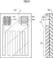
- (A) is a plan view schematically showing an example using the exterior sheet of the present invention, and (b) is a sectional view thereof.
- FIG. 1A is a plan view schematically showing an example of the film heater of the present invention.
- FIG. 1B is a cross-sectional view schematically showing an example of the film heater of the present invention.
- a bonding layer 2 which is solid at room temperature and exhibits adhesiveness by heating and melting is provided on one surface of a support sheet 1 made of a transparent thermoplastic resin sheet, and a conductive wire made of a conductive wire is provided on the bonding layer.
- Pattern 3 is provided.
- connection terminal portion 31, the lead portion 32 extending from the connection terminal portion 31, and the overall non-linear heater portion 33 continuing from the lead portion 32 are continuous with one conductive wire. It is provided as a linear pattern.
- end portion of the lead portion 32 extending linearly is referred to as a continuous terminal portion 31.
- the support sheet is made of a transparent thermoplastic resin sheet in order to produce a transparent film heater as a whole. If the film heater is transparent as a whole, it can be attached to various adherends without impairing the design of the adherend to be heated. Further, by using a thermoplastic resin sheet, it can be easily attached to an adherend having an uneven shape. In particular, when the adherend is a resin molded body, vacuum forming or heat pressing is performed.
- a film heater can be formed on the surface of a resin molded body by a molding method such as molding, laminating molding, in-mold molding, or insert molding.
- thermoplastic resin sheet ethylene-based resin, propylene-based resin, polyolefin-based resin, thermoplastic polyester-based resin, polyamide-based resin, polyvinyl chloride, polycarbonate, ABS resin and the like can also be used, and two or more of these are contained. It may be something to do. Especially for outdoor applications, it is preferable to use a polycarbonate resin having excellent mechanical strength and weather resistance. Inorganic fine powder or organic filler, dispersant, antioxidant, compatibilizer, ultraviolet stabilizer, antiblocking agent, antistatic agent and the like can be appropriately added to the thermoplastic resin sheet.
- the thickness of the thermoplastic resin sheet is preferably 0.030 mm to 1.000 mm, preferably 0.100 mm to 0.700 mm.
- the bonding layer is preferably a bonding layer that is solid at room temperature and exhibits adhesiveness by heating and melting. Since it is solid at room temperature and does not have tack, adhesion of dust and the like is suppressed, and handling at the time of sticking to the adherend is improved.
- a hot melt adhesive can be used.
- an adhesive composed of ethylene vinyl acetate, an olefin, synthetic rubber, polyamide, polyester or the like as a main component can be used.
- the thickness of the bonding layer is preferably 0.05 mm to 0.5 mm, preferably 0.1 mm to 0.3 mm.
- the bonding layer is used for embedding a conductive wire on the surface of a support sheet by utilizing the principle of attachment to an adherend or ultrasonic fusion.
- ultrasonic fusion the surface of the bonding layer is melted while feeding out the conductive wire, and the conductive wire can be embedded in the surface of the bonding layer.
- the material of the layer in which the conductive wire is embedded is a durable and hard material, or if a thin conductive wire is used in consideration of design, the resistance value of the conductive wire will increase due to the tension at the time of arrangement.
- the surface rubber hardness based on JIS K6301: 1995 is 50 ° or less.
- the bonding layer has a softening temperature higher than the operating temperature of the film heater of the present invention and melts at the temperature at which the conductive wire is embedded in the surface of the bonding layer.
- the conductive pattern can be formed by printing with a conductive ink such as silver paste or by etching a metal foil such as copper foil, but a circular conductive wire having a certain diameter in a cross-sectional view is formed as a predetermined pattern. It is preferable that the heater portion, the lead portion, and the connection terminal portion can be easily formed as one continuous linear shape.
- the conductive wires are configured to include at least a metal wire, preferably the metal wire is coated with a self-bonding insulating film.
- the metal wire is, for example, a metal wire such as copper, iron, gold, copper nickel, nickel chromium, iron nickel chromium, etc., but other materials may be used as long as they have conductivity. From the viewpoint of electrical resistance, durability, and cost, it is preferable to use copper or a copper alloy in which zinc, lead, tin, silver, aluminum, nickel, beryllium, zirconium, or the like is used alone or in combination with copper.
- the insulating film that coats the metal wire is an insulating resin film, and the conductive wire coated with the insulating film can be a commercially available enamel wire.
- Specific examples of the insulating resin film include polyester, polyethylene, polyurethane, polyvinyl chloride, polyamide, polyimide, polyesterimide, polyamideimide, and fluororesin.
- the insulating film is typically black, but may be colored in any color according to the color of the adherend to be heated.
- the diameter of the conductive wire constituting the conductive pattern is, for example, 0.03 mm to 0.2 mm.
- the film heater is transparent as a whole, and for that purpose, the conductive wire should be as thin as possible.
- the diameter of the conductive wire is preferably 0.05 mm to 0.15 mm.
- the length of the conductive wire depends on the pattern form of the conductive pattern and the like. To form a conductive pattern, it can typically be formed by drawing a conductive wire on the bonding layer and drawing a predetermined pattern form, and fixing by embedding the conductive wire at least on the surface of the bonding layer. can do.
- the conductive wire For embedding the conductive wire in the surface of the bonding layer, for example, it is desirable to embed the conductive wire in the surface of the support sheet by utilizing the principle of ultrasonic fusion.
- a wiring drawing device capable of melting the surface of the bonding layer while feeding out the conductive wire and embedding the conductive wire in the surface of the bonding layer can be used.
- the ultrasonic head provided in such a wiring drawing device, the conductive wire can be embedded in the surface of the joint layer by vibration and pressurization while feeding the conductive wire onto the surface of the joint layer.
- the conductive pattern By embedding the conductive wire in the surface of the joint layer, the conductive pattern can be positioned on the joint layer, and the displacement of the conductive wire due to an external impact or the like can be suppressed. Further, by embedding the conductive wire on the surface of the bonding layer, it is possible to reduce the degree of surface unevenness due to the arrangement of the conductive wire on the surface of the bonding layer.
- connection terminal portion 31 the connection terminal portion 31, the lead portion 32 extending from the connection terminal portion 31, and the overall non-linear heater portion 33 continuing from the lead portion 32 are one. It is provided as a continuous linear pattern composed of conductive wires.
- connection terminal portion 31 the end portion of the lead portion 32 drawn from one continuous conductive wire is used as the connection terminal portion 31.
- the connection terminal portion may be further provided with a conductive piece made of a metal plate on the connection terminal portion in order to improve the connection efficiency with the external electrode.
- the metal plate for example, copper, copper alloy, iron, iron and nickel alloy and the like can be used.
- the conductive wire is covered with an insulating film, the insulating film covering the conductive wire at the connection terminal portion is removed to expose the metal wire inside. As a method of exposing, cutting with a milling device or the like is possible, but the insulating film can be melted and removed by heat when soldering to a metal plate or an external electrode.
- the heater portion 33 is routed from the lead portion 32 extending from the connection terminal portion 31 and is formed as a non-linear linear pattern as a whole.
- the heater portion 33 has a relatively short length.
- the bent part and the straight part having a relatively long length are repeated, and the pattern is bent and meandered at a plurality of places.
- the pattern of the heater portion can be any pattern in consideration of the shape of the adherend, the heating area, and the heating efficiency, and may be a repeating curved shape that does not include a straight portion or a spiral shape. In FIG.
- the conductive pattern is composed of a pair of left and right connection terminal portions 31 and a pair of left and right lead portions 32 centered on the heater portion 33, and the lead portion 32a starts from the end of one connection terminal portion 31a by a conductive wire.
- the heater portion 33 is formed by the conductive wire drawn from the lead portion 32a, the other lead portion 32b is extended from the heater portion 33, and the other lead portion 32b is extended to the other connection terminal portion 31b.
- a continuous linear heater portion 33, a lead portion 32, and a connection terminal portion 31 are formed of the conductive wires of the above.
- an antifouling layer an antifogging layer, an antistatic layer, a hard coat layer and the like may be formed on the surface opposite to the bonding layer of the support sheet, if necessary.
- FIG. 2A is a plan view schematically showing an example of the film heater of the present invention.
- FIG. 2B is a cross-sectional view schematically showing an example of the film heater of the present invention.
- a conductive pattern 22 made of a conductive wire is provided on one surface of a support sheet 1 made of a transparent thermoplastic resin sheet.
- the conductive pattern is a non-linear shape as a whole connected to the connection terminal portions 21a and 21b (21 in FIG.
- the heater portions 231 and 232 are provided as a continuous linear pattern composed of a single conductive wire.
- a conductive pattern it can typically be formed by drawing a conductive wire around on the support sheet and drawing a predetermined pattern form, and fixing by embedding the conductive wire at least on the surface of the support sheet. can do.
- a wiring drawing device capable of melting the surface of a support sheet made of a thermoplastic resin while feeding out the conductive wire and embedding the conductive wire in the surface of the support sheet can be used.
- the conductive wire can be embedded in the surface of the support sheet by vibration and pressurization while feeding the conductive wire onto the surface of the support sheet.
- the conductive pattern can be positioned on the support sheet, and the displacement of the conductive wire due to an external impact or the like can be suppressed.
- the conductive wire on the surface of the support sheet it is possible to reduce the degree of surface unevenness due to the arrangement of the conductive wire on the surface of the support sheet.
- a bonding layer that is solid at room temperature and exhibits adhesiveness by heating and melting is provided on one surface of the support sheet 1, and the conductive wire is provided on the surface of the bonding layer.
- a conductive pattern composed of conductive wires may be provided on the bonding layer.
- the conductive pattern is an overall non-linear heater connected to the connection terminal portions 21a and 21b, the lead wires 221 and 222 extending from the connection terminal portions 21a and 21b, and the lead wires 221 and 222.
- the portions 231 and 232 are provided as a continuous linear pattern composed of one conductive wire.
- the conductive pattern includes at least two first lead wires 221 and second lead wire 222, and a first lead wire 221 extending from one connection terminal portion 21 in which the conductive wires are bent at a plurality of places. It has a connected first heater section 231 and a second heater section 232 connected to the second lead wire 222, and the first heater section 231 and the second heater section 232 are arranged in parallel. By arranging the first heater portion 231 and the second heater portion 232 in parallel, each of these heater portions is connected to the two connection terminal portions. The combined resistance of the conductive wires arranged in parallel is lower than the combined resistance of the conductive wires arranged in series between the two connection terminals using the conductive wires of the same length.
- connection terminal portion 21a is arranged in parallel as a continuous linear pattern composed of one conductive wire by forming a lattice shape in which the linear patterns in which the conductive wires are bent at a plurality of points intersect vertically and horizontally.
- the heater portions 231 and 232 are routed from the lead wire extending from the connection terminal portion 21 and formed as a non-linear linear pattern as a whole.
- the heater portions 231 and 232 are relatively long. A short bent part and a relatively long straight part are repeated, and the pattern is bent and meandered at a plurality of places.
- the pattern of the heater portion can be any pattern in consideration of the shape of the adherend, the heating area, and the heating efficiency, and may be a repeating curved shape that does not include a straight portion or a spiral shape. In FIG.
- the conductive pattern is composed of a pair of left and right connection terminal portions 21a and 21b and a pair of left and right lead portions 221a and 222a, 221b and 222b, and becomes one connection terminal portion 21a by a conductive wire.
- a folded shape pattern is formed, one of the first lead wires 221a is extended from the folded shape pattern, and the first heater portion 231 is formed by the conductive wire drawn from the first lead wire 221a, and the first heater portion 231 is formed.
- the other first lead wire 221b is extended from the heater portion 231 to form the other folded-shaped connection terminal portion 21b, and the other second lead wire 222b is extended from the other connection terminal portion 21b.
- the second heater portion 232 is formed by the conductive wire drawn from the other second lead wire 222b, and one second lead wire 222a is extended from the second heater portion 232 to connect with the one connection terminal portion 21a.
- a folded shape pattern is formed that is bent in a direction that intersects with the folded shape pattern, and one connection terminal portion 21a is formed in a lattice shape in which a linear pattern in which conductive wires are bent at a plurality of points intersect vertically and horizontally. There is.
- FIG. 3 shows an example in which both the pair of left and right connection terminal portions 21a and 21b are formed in a lattice shape in which a linear pattern in which conductive wires are bent at a plurality of locations intersect vertically and horizontally.
- an exterior sheet made of another transparent thermoplastic resin sheet that covers the conductive pattern is provided on the surface of the support sheet provided with the conductive pattern, and the exterior sheet is provided with a connection terminal portion. It can be a film heater provided with a through hole that exposes at least a part of the above.
- FIG. 4A is a plan view schematically showing an example of the exterior sheet of the present invention.
- FIG. 4B is a cross-sectional view schematically showing an example of the exterior sheet of the present invention.
- the exterior sheet 3 having substantially the same dimensions as the support sheet is provided with through holes 331a and 331b for exposing at least a part of the connection terminal portion to the outside.
- thermoplastic resin sheet similar to the support sheet can be used, and the surface of the support sheet on which the conductive pattern is formed can be bonded by heat treatment and / or press treatment. If necessary, an adhesive layer, an adhesive layer, a heat seal layer, or the like may be interposed between the support sheet and the exterior sheet for bonding.
- the exterior sheet may be provided with a through hole that exposes at least a part of the connection terminal portion to the outside.
- a cutting means such as punching with a die or a laser device can be used to form a through hole in the exterior sheet for exposing the contact terminal portion. Specifically, a biku blade, a cutting blade, a laser cutter, or A milling device or the like can be used.
- FIG. 5A is a plan view schematically showing an example using the exterior sheet of the present invention.
- FIG. 5B is a cross-sectional view schematically showing an example using the exterior sheet of the present invention.
- the entire surface of the support sheet 1 on which the conductive pattern is formed is covered with the exterior sheet 3 except for the through hole 331, whereby the overall transparent thermoplastic resin sheet is used.
- the connection terminal portion 21 can be reliably electrically connected to an external power source. Further, it becomes possible to protect the heater portion and the lead portion on the surface of the support sheet by covering them with the exterior sheet.
- an antifouling layer, an antifogging layer, an antistatic layer, a hard coat layer, or the like may be formed on the surface of the exterior sheet.
- the adhesive layer may be provided on the surface of the support sheet opposite to the surface on which the conductive pattern is provided. By using the adhesive layer, it can be easily attached to an adherend having an uneven shape.
- the adhesive layer for example, an acrylic-based, urethane-based, epoxy-based, rubber-based, polyester-based, cellulose-based, or emulsion-based adhesive can be used. Further, if necessary, fillers, tackifiers, hardeners and the like can be appropriately used as additives for improving the characteristics of the pressure-sensitive adhesive.
- the thickness of the adhesive layer is not particularly limited as long as the adhesive strength can be obtained, and is usually 20 ⁇ m to 200 ⁇ m, preferably about 25 ⁇ m to 75 ⁇ m.
- the adhesive can be formed by using a coating method such as gravure coating, gravure reverse coating, comma coating, knife coating, and die coating.
- Example 1 A thermoplastic resin sheet (polycarbonate sheet DPI-AO manufactured by Mitsubishi Plastics, thickness 0.075 mm) to be a support sheet was prepared, and a bonding layer was formed on the surface of the support sheet.
- a polyester hot melt Toagosei Aron Melt PES-111EHW, thickness 0.1 mm was used.
- the surface rubber hardness of the joint layer was measured from a spring type A type based on JIS K6301: 1995 using HARDNESSTESTER ATYPE manufactured by Furusato Seiki Seisakusho. The measured surface rubber hardness was 50 °.
- a conductive wire (ELEKTRISOLA self-bonding coating lead wire AB15 ⁇ 0.1 mm) was applied to the surface of the bonding layer, and a wiring drawing device (Ruhramat WCE150, setting condition: USP1200, speed40%) equipped with an ultrasonic head was used. It was embedded to form a conductive pattern as shown in FIG.
- the conductive pattern has a lead portion length of 130 mm, a heater portion of 90 mm in a straight portion, a folded portion (pitch) of 10 mm, a number of folds (the number of lines in the straight portion) of 8 times, and a connection terminal portion of 17 mm in a straight portion. ..
- the film was cut into a length of 170 mm and a width of 120 mm to prepare a film heater.
- the resistance value before and after embedding was measured and the resistance increase rate was calculated.
- the resistance value was measured using an IWATSU multimeter.
- the resistance increase rate of the produced film heater was 2.0%.
- Example 2 A film heater was produced in the same manner as in Example 1 except that a bonding layer having a surface rubber hardness of 43 ° was used. The resistance increase rate of the produced film heater was 0.1%.
- Example 1 A film heater was produced in the same manner as in Example 1 except that a conductive pattern was directly formed on the surface of the support sheet without forming a bonding layer.
- the resistance increase rate of the produced film heater was 15.9%.
- Example 3 A thermoplastic resin sheet (polycarbonate sheet DPI-AO manufactured by Mitsubishi Resin Co., Ltd., thickness 0.075 mm) to be a support sheet is prepared, and a conductive wire (self-bonding film conducting wire AB15 ⁇ 0.10 mm manufactured by ELEKTRISOLA) is placed on the surface of the support sheet. It was embedded using a wiring drawing device equipped with an ultrasonic head (WCE150 manufactured by Ruhlamat, setting conditions: USP1200, speed 40%) to form a conductive pattern as shown in FIG. Regarding the conductive pattern, the lengths of the first heater portion and the second heater portion were set to 525 mm and 735 mm, respectively.
- WCE150 ultrasonic head
- the length of the heater portion is the length of the portion where the straight portion is repeated at a constant pitch (the bracket portion in FIG. 2).
- the first connection terminal portion has a straight line portion of 17 mm, a folded portion (pitch) of 0.3 mm, and the number of turns is a grid shape obtained by intersecting the folded shapes of 6 times, and the second connection terminal portion has a straight portion of 17 mm and a folded portion (folded portion).
- the pitch was 0.3 mm, and the number of turns was 6 times.
- a film heater was produced by punching a die into a length of 170 mm and a width of 120 mm.
- Example 4 A thermoplastic resin sheet (polycarbonate sheet DPI-AO thickness 0.075 mm manufactured by Mitsubishi Resin Co., Ltd.) to be an exterior sheet is attached to the surface of the support sheet to which the conductive pattern of Example 3 is wired, and a vacuum laminating machine (180 ° C.) is attached. After heat-pressing with 60 N / cm 2 ) and sufficiently adhering it on the support sheet, a milling device is used on the exterior sheet to expose the connection terminal part, and a through hole of 10 mm ⁇ 10 mm is formed at the position of the connection terminal part. Formed. At this time, the insulating film covering the conductive wire of the connection terminal exposed in the through hole was removed to expose the metal wire inside. Finally, a film heater was produced by punching a die into a length of 170 mm and a width of 120 mm.
Landscapes
- Surface Heating Bodies (AREA)
Abstract
Provided is a film heater which is transparent as a whole, and which can be bonded to various adherends without compromising the design of the adherend, which is to be heated. This film heater is characterized in that: a joining layer which is a solid at room temperature and which exhibits adhesion when melted by heating is provided on one surface of a support sheet comprising a transparent thermoplastic resin sheet; an electrically conductive pattern comprising electrically conductive wires is provided on the joining layer; and in the electrically conductive pattern, connecting terminal portions, lead portions extending from the connecting terminal portions, and a heater portion which is continuous with the lead portions and which is non-linear as a whole are provided as a continuous thread-like pattern comprising one electrically conductive wire.
Description
本発明はフィルムヒータに係り、特に、外部電源と電気的に接続可能な導電性パターンをフィルム上に設けたフィルムヒータに関する。
The present invention relates to a film heater, and more particularly to a film heater provided on a film with a conductive pattern that can be electrically connected to an external power source.
従来から、加熱対象となる被着体に貼着させて使用する、氷雪付着防止や融雪、曇り防止、保温などを目的とした、加熱用の導電性パターンを有したフィルム状の面状発熱体が知られている。
Conventionally, a film-like planar heating element having a conductive pattern for heating, which is used by being attached to an adherend to be heated for the purpose of preventing ice / snow adhesion, snow melting, fogging, and heat retention. It has been known.
例えば、特許文献1には、任意の形状に加工された裸ニクロム線を、絶縁材料からなる粘着層を介して2枚の多層複合フィルムの内部に配設した面状発熱体が開示されており、この面状発熱体を、両面粘着テープ、両面粘着フィルム等によって加熱対象物に貼着することが記載されている。
特許文献2には、柔軟性を有する面状の発熱部と、この発熱部を内包するよう形成された半硬化状態の半硬化樹脂被覆層と、を有する硬質面状発熱体製造用半硬化シートが開示されている。発熱部を内包する半硬化樹脂被覆層は、半硬化状態(Bステージ)であり、柔軟性および可塑性を有すると共に、その表面は粘着性を有しているため、あらゆる被着体の形状に対して追従し、貼付させることができることが記載されている。 For example,Patent Document 1 discloses a planar heating element in which a bare nichrome wire processed into an arbitrary shape is arranged inside two multilayer composite films via an adhesive layer made of an insulating material. , It is described that this planar heating element is attached to a heating object by a double-sided adhesive tape, a double-sided adhesive film, or the like.
Patent Document 2 describes a semi-cured sheet for manufacturing a hard planar heating element, which comprises a flexible planar heating element and a semi-cured semi-cured resin coating layer formed so as to include the heat-generating portion. Is disclosed. The semi-cured resin coating layer containing the heat generating portion is in a semi-cured state (B stage), has flexibility and plasticity, and has an adhesive surface, so that it can be applied to any shape of the adherend. It is described that it can be followed and pasted.
特許文献2には、柔軟性を有する面状の発熱部と、この発熱部を内包するよう形成された半硬化状態の半硬化樹脂被覆層と、を有する硬質面状発熱体製造用半硬化シートが開示されている。発熱部を内包する半硬化樹脂被覆層は、半硬化状態(Bステージ)であり、柔軟性および可塑性を有すると共に、その表面は粘着性を有しているため、あらゆる被着体の形状に対して追従し、貼付させることができることが記載されている。 For example,
特許文献3には、所定のパターンに形成された金属線抵抗体を、中心角が90度以下である扇形の切欠部を有する円形シート状の可撓性透明基材の表面または内部に備えてなることを特徴とする信号灯用の面状ヒータが開示されており、扇形の切欠部の直線部を互いに接触または近接させ、可撓性透明基材を円形シートから円錐シートの形状に変形させることで、信号灯の表示窓がドーム形の形状であっても密着させやすいことが記載されている。
In Patent Document 3, a metal wire resistor formed in a predetermined pattern is provided on the surface or inside of a circular sheet-shaped flexible transparent base material having a fan-shaped notch having a central angle of 90 degrees or less. A planar heater for a traffic light is disclosed, wherein the straight portions of the fan-shaped notches are brought into contact with or close to each other to deform the flexible transparent substrate from a circular sheet to a conical sheet. It is described that even if the display window of the signal light has a dome shape, it is easy to make close contact with it.
特許文献1に開示されている発明は、2枚の多層複合フィルムの間の内部に配線固定用粘着層を用いて裸ニクロム線が配設され、多層複合フィルムの周辺部分がヒートシールされており、構成が複雑である。
特許文献2に開示されている発明は、特殊な樹脂皮膜を用いる必要があり、光硬化法により半硬化樹脂被覆層を完全硬化させるなど特殊な設備が必要で、施工法が複雑になりやすい。
特許文献3に開示されている発明は、信号灯の表示窓がドーム形の形状である場合には効果的であるが、それ以外に使用することは難しい。 In the invention disclosed inPatent Document 1, a bare nichrome wire is disposed inside between two multilayer composite films using an adhesive layer for fixing wiring, and a peripheral portion of the multilayer composite film is heat-sealed. , The configuration is complicated.
The invention disclosed inPatent Document 2 requires the use of a special resin film, requires special equipment such as completely curing the semi-cured resin coating layer by a photocuring method, and tends to complicate the construction method.
The invention disclosed inPatent Document 3 is effective when the display window of the signal light has a dome shape, but it is difficult to use it in other cases.
特許文献2に開示されている発明は、特殊な樹脂皮膜を用いる必要があり、光硬化法により半硬化樹脂被覆層を完全硬化させるなど特殊な設備が必要で、施工法が複雑になりやすい。
特許文献3に開示されている発明は、信号灯の表示窓がドーム形の形状である場合には効果的であるが、それ以外に使用することは難しい。 In the invention disclosed in
The invention disclosed in
The invention disclosed in
また、導電線の配設において、特許文献1では、配線固定用粘着層上に裸ニクロム線が配設されるが、粘着層は、製造工程でゴミが付着しやすく、また成形した裸ニクロム線の形状が崩れやすいという問題がある。特許文献2では、発熱用導電性糸からなる横糸と絶縁性糸からなる縦糸とを所定間隔で交差させて織り込まれた特定の織布を発熱部として用いており、特許文献3では、可撓性透明基材の表面に蛇行状の溝を彫り、この溝に沿って発熱線抵抗体を埋設して発熱部を形成しているため、構成、製造工程が複雑になってしまう。
本発明者らは、より製造が容易で、被着体の意匠性を損なうことなく、凹凸があるような形状の被着体に対しても簡単に貼着することができるフィルムヒータとして、超音波融着の原理を活用して導電線を支持シートの表面に埋め込むことを検討した。
超音波融着は、導電線を繰り出しながら熱可塑性樹脂からなる支持シートの表面を溶融させ、導電線を支持シートの表面に埋め込むことができる。しかし支持シートの材質が耐久性のある硬い材料であったり、意匠性を考慮して細い導電線を用いたりした場合、配設時の張力により導電線が細くなってしまい、その結果導電線の抵抗値が増加してしまうという問題が生じた。また、導電線が太い場合であっても、導電線と支持シートとの間のずり応力の増大に起因すると考えられる抵抗値の増加が認められた。さらに、導電線の抵抗値の増加の問題は、導電線が被覆されている場合に顕著であることも認められた。 Further, in the arrangement of the conductive wire, inPatent Document 1, the bare nichrome wire is arranged on the adhesive layer for fixing the wiring, but the adhesive layer is liable to adhere dust in the manufacturing process, and the molded bare nichrome wire is formed. There is a problem that the shape of the is easily collapsed. Patent Document 2 uses a specific woven fabric woven by crossing a weft yarn made of a conductive yarn for heat generation and a warp yarn made of an insulating yarn at predetermined intervals as a heat generating portion, and Patent Document 3 uses a flexible woven fabric. Since a meandering groove is carved on the surface of the transparent transparent base material and a heating wire resistor is embedded along the groove to form a heat generating portion, the configuration and manufacturing process become complicated.
The present inventors are super as a film heater that is easier to manufacture and can be easily attached to an adherend having an uneven shape without impairing the design of the adherend. It was examined to embed the conductive wire on the surface of the support sheet by utilizing the principle of ultrasonic fusion.
In ultrasonic fusion, the surface of the support sheet made of a thermoplastic resin is melted while the conductive wire is fed out, and the conductive wire can be embedded in the surface of the support sheet. However, if the material of the support sheet is a durable and hard material, or if a thin conductive wire is used in consideration of design, the conductive wire becomes thin due to the tension at the time of arrangement, and as a result, the conductive wire becomes thin. There was a problem that the resistance value increased. Further, even when the conductive wire was thick, an increase in the resistance value, which was considered to be caused by an increase in the shear stress between the conductive wire and the support sheet, was observed. Furthermore, it was also found that the problem of increasing the resistance value of the conductive wire was remarkable when the conductive wire was coated.
本発明者らは、より製造が容易で、被着体の意匠性を損なうことなく、凹凸があるような形状の被着体に対しても簡単に貼着することができるフィルムヒータとして、超音波融着の原理を活用して導電線を支持シートの表面に埋め込むことを検討した。
超音波融着は、導電線を繰り出しながら熱可塑性樹脂からなる支持シートの表面を溶融させ、導電線を支持シートの表面に埋め込むことができる。しかし支持シートの材質が耐久性のある硬い材料であったり、意匠性を考慮して細い導電線を用いたりした場合、配設時の張力により導電線が細くなってしまい、その結果導電線の抵抗値が増加してしまうという問題が生じた。また、導電線が太い場合であっても、導電線と支持シートとの間のずり応力の増大に起因すると考えられる抵抗値の増加が認められた。さらに、導電線の抵抗値の増加の問題は、導電線が被覆されている場合に顕著であることも認められた。 Further, in the arrangement of the conductive wire, in
The present inventors are super as a film heater that is easier to manufacture and can be easily attached to an adherend having an uneven shape without impairing the design of the adherend. It was examined to embed the conductive wire on the surface of the support sheet by utilizing the principle of ultrasonic fusion.
In ultrasonic fusion, the surface of the support sheet made of a thermoplastic resin is melted while the conductive wire is fed out, and the conductive wire can be embedded in the surface of the support sheet. However, if the material of the support sheet is a durable and hard material, or if a thin conductive wire is used in consideration of design, the conductive wire becomes thin due to the tension at the time of arrangement, and as a result, the conductive wire becomes thin. There was a problem that the resistance value increased. Further, even when the conductive wire was thick, an increase in the resistance value, which was considered to be caused by an increase in the shear stress between the conductive wire and the support sheet, was observed. Furthermore, it was also found that the problem of increasing the resistance value of the conductive wire was remarkable when the conductive wire was coated.
本発明は、透明な熱可塑性樹脂シートからなる支持シートの一方の面に、常温では固体で加熱溶融により接着性を示す接合層を設け、該接合層上に導電線からなる導電性パターンが設けられ、該導電性パターンは、接続端子部と、該接続端子部から延びたリード部と、該リード部から続く全体として非直線状のヒータ部とが、一本の導電線からなる連続した線状パターンとして設けられたことを特徴とするフィルムヒータである。
本発明は、1つの実施形態において、前記導電性パターンが、一定の径を有する断面視で円形の導電線が超音波融着により前記接合層の表面に所定のパターンに埋め込まれてなるフィルムヒータである。
本発明では、前記接合層のJIS K6301:1995に基づく表面ゴム硬度が50°以下であるとよい。具体的には、前記接合層がホットメルト接着剤からなるとよい。
本発明では、前記支持シートがポリカーボネート樹脂からなるとよい。
本発明では、前記導電性パターンを構成する導電線が、自己融着性の絶縁被膜により被覆されているとよい。
本発明では、前記導電性パターンを構成する導電線の直径が150μm以下であるとよい。
また、本発明では、前記導電性パターンが、導電線が複数箇所で折れ曲がった2つの接続端子部と、該2つの接続端子部の1つから延びた少なくとも2本のリード部と、該2本のリード部と繋がった少なくとも2つのヒータ部とを有し、前記少なくとも2つのヒータ部を並列に配設したフィルムヒータとすることができる。
本発明では、前記接続端子部は、導電線が複数箇所で折れ曲がった線状パターンが縦横に交差した格子形状で構成することができる。
本発明では、前記支持シートの前記導電性パターンを設けた面に、前記導電性パターンを覆う別の透明な熱可塑性樹脂シートからなる外装シートが設けられ、該外装シートには、前記接続端子部の少なくとも一部を外部に露出させる貫通孔が設けられたフィルムヒータとすることができる。
本発明では、前記接続端子部上に、さらに金属板が設けることができる。
本発明では、前記導電性パターンを構成する導電線が、自己融着性の絶縁皮膜により被覆されているとよい。
前記支持シートの導電性パターンが設けられた面とは反対の面に粘着層を設けた構成とすることができる。 In the present invention, a bonding layer that is solid at room temperature and exhibits adhesiveness by heating and melting is provided on one surface of a support sheet made of a transparent thermoplastic resin sheet, and a conductive pattern made of conductive wires is provided on the bonding layer. The conductive pattern is a continuous line consisting of a connection terminal portion, a lead portion extending from the connection terminal portion, and an overall non-linear heater portion continuing from the lead portion. It is a film heater characterized by being provided as a shape pattern.
In one embodiment, the present invention is a film heater in which the conductive pattern has a certain diameter and a circular conductive wire is embedded in a predetermined pattern on the surface of the bonding layer by ultrasonic fusion. Is.
In the present invention, the surface rubber hardness of the bonding layer based on JIS K6301: 1995 is preferably 50 ° or less. Specifically, the bonding layer may be made of a hot melt adhesive.
In the present invention, the support sheet may be made of a polycarbonate resin.
In the present invention, it is preferable that the conductive wires constituting the conductive pattern are covered with a self-bonding insulating film.
In the present invention, the diameter of the conductive wire constituting the conductive pattern is preferably 150 μm or less.
Further, in the present invention, the conductive pattern has two connection terminal portions in which the conductive wire is bent at a plurality of locations, and at least two lead portions extending from one of the two connection terminal portions, and the two conductor portions. A film heater having at least two heater portions connected to the lead portion of the above and having the at least two heater portions arranged in parallel can be obtained.
In the present invention, the connection terminal portion can be formed in a lattice shape in which a linear pattern in which conductive wires are bent at a plurality of points intersect vertically and horizontally.
In the present invention, an exterior sheet made of another transparent thermoplastic resin sheet that covers the conductive pattern is provided on the surface of the support sheet provided with the conductive pattern, and the exterior sheet is provided with the connection terminal portion. It can be a film heater provided with a through hole that exposes at least a part of the above.
In the present invention, a metal plate can be further provided on the connection terminal portion.
In the present invention, it is preferable that the conductive wires constituting the conductive pattern are covered with a self-bonding insulating film.
The adhesive layer may be provided on the surface of the support sheet opposite to the surface on which the conductive pattern is provided.
本発明のフィルムヒータは、全体として透明なフィルムヒータであり、加熱対象となる被着体の意匠性を損なうことなく、さまざまな被着体に貼着可能である。特に支持シートの表面に表面ゴム硬度の小さい接合層を形成することにより、支持シートの材質が耐久性のある硬い材料であっても導電線の抵抗値が増加することを抑えることができる。また接合層は熱接着可能であり、被着体が樹脂成形体の場合、樹脂成形と同時に樹脂成形体の表面にフィルムヒータを形成することができるインモールド転写が可能である。また、導電性パターンを一本の導電線で連続形成でき、製造が容易となり、導電性パターンを形成した支持シートの全面を外装シートにより覆うことで、導電性パターンを保護することが可能になる。
本発明は、成形性がよく、機械的強度が高く、被着体に対する接着性に優れたフィルムヒータで、氷雪付着防止や融雪、曇り防止、保温など目的とした各種用途に適用可能である。 The film heater of the present invention is a transparent film heater as a whole, and can be attached to various adherends without impairing the design of the adherend to be heated. In particular, by forming a bonding layer having a low surface rubber hardness on the surface of the support sheet, it is possible to suppress an increase in the resistance value of the conductive wire even if the material of the support sheet is a durable and hard material. Further, the bonding layer can be heat-bonded, and when the adherend is a resin molded body, in-mold transfer capable of forming a film heater on the surface of the resin molded body at the same time as resin molding is possible. In addition, the conductive pattern can be continuously formed by a single conductive wire, which facilitates manufacturing. By covering the entire surface of the support sheet on which the conductive pattern is formed with an exterior sheet, the conductive pattern can be protected. ..
The present invention is a film heater having good moldability, high mechanical strength, and excellent adhesiveness to an adherend, and can be applied to various applications such as prevention of ice and snow adhesion, snow melting, fogging prevention, and heat retention.
以下に、図面を参照しながら本発明の実施の形態について説明する。
[第1の実施形態]
図1(a)は本発明のフィルムヒータの一例を模式的に示す平面図である。図1(b)は本発明のフィルムヒータの一例を模式的に示す断面図である。
図1によると、透明な熱可塑性樹脂シートからなる支持シート1の一方の面に、常温では固体で加熱溶融により接着性を示す接合層2を設け、該接合層上に導電線からなる導電性パターン3が設けられている。導電性パターン3は、接続端子部31と、接続端子部31から延びたリード部32と、リード部32から続く全体として非直線状のヒータ部33とが、一本の導電線からなる連続した線状パターンとして設けられている。図1では直線状に延びたリード部32の端部を続端子部31としている。 Hereinafter, embodiments of the present invention will be described with reference to the drawings.
[First Embodiment]
FIG. 1A is a plan view schematically showing an example of the film heater of the present invention. FIG. 1B is a cross-sectional view schematically showing an example of the film heater of the present invention.
According to FIG. 1, abonding layer 2 which is solid at room temperature and exhibits adhesiveness by heating and melting is provided on one surface of a support sheet 1 made of a transparent thermoplastic resin sheet, and a conductive wire made of a conductive wire is provided on the bonding layer. Pattern 3 is provided. In the conductive pattern 3, the connection terminal portion 31, the lead portion 32 extending from the connection terminal portion 31, and the overall non-linear heater portion 33 continuing from the lead portion 32 are continuous with one conductive wire. It is provided as a linear pattern. In FIG. 1, the end portion of the lead portion 32 extending linearly is referred to as a continuous terminal portion 31.
[第1の実施形態]
図1(a)は本発明のフィルムヒータの一例を模式的に示す平面図である。図1(b)は本発明のフィルムヒータの一例を模式的に示す断面図である。
図1によると、透明な熱可塑性樹脂シートからなる支持シート1の一方の面に、常温では固体で加熱溶融により接着性を示す接合層2を設け、該接合層上に導電線からなる導電性パターン3が設けられている。導電性パターン3は、接続端子部31と、接続端子部31から延びたリード部32と、リード部32から続く全体として非直線状のヒータ部33とが、一本の導電線からなる連続した線状パターンとして設けられている。図1では直線状に延びたリード部32の端部を続端子部31としている。 Hereinafter, embodiments of the present invention will be described with reference to the drawings.
[First Embodiment]
FIG. 1A is a plan view schematically showing an example of the film heater of the present invention. FIG. 1B is a cross-sectional view schematically showing an example of the film heater of the present invention.
According to FIG. 1, a
支持シートは、透明な熱可塑性樹脂シートからなることが、全体として透明なフィルムヒータを作製する上で好ましい。全体として透明なフィルムヒータであれば加熱対象となる被着体の意匠性を損なうことなく、さまざまな被着体に貼着可能である。
また、熱可塑性樹脂シートを用いることにより、凹凸があるような形状の被着体に対して簡単に貼着することができ、特に、被着体が樹脂成形体の場合、真空成型、熱プレス成型、ラミネート成型、インモールド成型、インサート成型などの成型方法で、樹脂成形体の表面にフィルムヒータを形成することができる。 It is preferable that the support sheet is made of a transparent thermoplastic resin sheet in order to produce a transparent film heater as a whole. If the film heater is transparent as a whole, it can be attached to various adherends without impairing the design of the adherend to be heated.
Further, by using a thermoplastic resin sheet, it can be easily attached to an adherend having an uneven shape. In particular, when the adherend is a resin molded body, vacuum forming or heat pressing is performed. A film heater can be formed on the surface of a resin molded body by a molding method such as molding, laminating molding, in-mold molding, or insert molding.
熱可塑性樹脂シートとしては、エチレン系樹脂、プロピレン系樹脂、ポリオレフィン系樹脂、熱可塑性ポリエステル系樹脂、ポリアミド系樹脂、ポリ塩化ビニル、ポリカーボネート、ABS樹脂等を用いることもでき、これらを2種以上含有するものであってもよい。特に屋外の用途においては、機械的強度、耐候性に優れるポリカーボネート系樹脂を用いるのがよい。
熱可塑性樹脂シートには無機微細粉末あるいは有機フィラー、分散剤、酸化防止剤、相溶化剤、紫外線安定剤、アンチブロッキング剤、帯電防止剤等を適宜添加することができる。
熱可塑性樹脂シートの厚みは、0.030mm~1.000mm、好ましくは0.100mm~0.700mmであるとよい。 As the thermoplastic resin sheet, ethylene-based resin, propylene-based resin, polyolefin-based resin, thermoplastic polyester-based resin, polyamide-based resin, polyvinyl chloride, polycarbonate, ABS resin and the like can also be used, and two or more of these are contained. It may be something to do. Especially for outdoor applications, it is preferable to use a polycarbonate resin having excellent mechanical strength and weather resistance.
Inorganic fine powder or organic filler, dispersant, antioxidant, compatibilizer, ultraviolet stabilizer, antiblocking agent, antistatic agent and the like can be appropriately added to the thermoplastic resin sheet.
The thickness of the thermoplastic resin sheet is preferably 0.030 mm to 1.000 mm, preferably 0.100 mm to 0.700 mm.
接合層は、常温では固体で加熱溶融により接着性を示す接合層であるとよい。常温では固体でタックを有しないことにより、ゴミ等の付着が抑えられ、被着体への貼り付け時のハンドリングも良好になる。具体的にはホットメルト接着剤を用いることができる。ホットメルト接着剤としては、主成分としてエチレン酢酸ビニル、オレフィン、合成ゴム、ポリアミド、ポリエステルなどをベースとして構成されたものを用いることができる。
接合層の厚みは0.05mm~0.5mm、好ましくは0.1mm~0.3mmであるとよい。
接合層は、被着体への貼り付けや超音波融着の原理を活用して導電線を支持シートの表面に埋め込むために用いられる。超音波融着は、導電線を繰り出しながら接合層の表面を溶融させ、導電線を接合層の表面に埋め込むことができる。導電線を埋め込む層の材質が耐久性のある硬い材料であったり、意匠性を考慮して細い導電線を用いたりした場合、配設時の張力により導電線の抵抗値が増加してしまため、接合層としてはJIS K6301:1995に基づく表面ゴム硬度が50°以下であることが好ましい。これにより比較的硬いポリカーボネート樹脂を支持シートに用いても導電線の抵抗値増加を抑えることができる。
接合層は、本発明のフィルムヒータの使用温度よりも高い軟化温度を有するとともに、導電線を接合層の表面に埋め込む際の温度で溶融するものであるのが好ましい。
導電性パターンは、銀ペースト等の導電性インキを用いた印刷や銅箔等の金属箔のエッチングによりを形成することもできるが、一定の径を有する断面視で円形の導電線を所定のパターンに形成することが、一つの連続した線状としてヒータ部とリード部、接続端子部を容易に形成できる点で好ましい。
導電性パターンを導電線で構成する場合、その導電線は、少なくとも金属線を含んで構成され、好ましくは金属線が自己融着性の絶縁皮膜により被覆されてなるものとする。金属線は、例えば、銅、鉄、金、銅ニッケル、ニッケルクロム、鉄ニッケルクロム等の金属線であるが、導電性を有するものであれば他の材料を用いることもできる。電気抵抗や耐久性、コストの観点から、金属線として銅又は銅に亜鉛や鉛、錫、銀、アルミ、ニッケル、ベリリウム、ジルコニウムなどを単独もしくは複数組み合わせてある銅合金を用いることが好ましい。 The bonding layer is preferably a bonding layer that is solid at room temperature and exhibits adhesiveness by heating and melting. Since it is solid at room temperature and does not have tack, adhesion of dust and the like is suppressed, and handling at the time of sticking to the adherend is improved. Specifically, a hot melt adhesive can be used. As the hot melt adhesive, an adhesive composed of ethylene vinyl acetate, an olefin, synthetic rubber, polyamide, polyester or the like as a main component can be used.
The thickness of the bonding layer is preferably 0.05 mm to 0.5 mm, preferably 0.1 mm to 0.3 mm.
The bonding layer is used for embedding a conductive wire on the surface of a support sheet by utilizing the principle of attachment to an adherend or ultrasonic fusion. In ultrasonic fusion, the surface of the bonding layer is melted while feeding out the conductive wire, and the conductive wire can be embedded in the surface of the bonding layer. If the material of the layer in which the conductive wire is embedded is a durable and hard material, or if a thin conductive wire is used in consideration of design, the resistance value of the conductive wire will increase due to the tension at the time of arrangement. As the bonding layer, it is preferable that the surface rubber hardness based on JIS K6301: 1995 is 50 ° or less. As a result, even if a relatively hard polycarbonate resin is used for the support sheet, an increase in the resistance value of the conductive wire can be suppressed.
It is preferable that the bonding layer has a softening temperature higher than the operating temperature of the film heater of the present invention and melts at the temperature at which the conductive wire is embedded in the surface of the bonding layer.
The conductive pattern can be formed by printing with a conductive ink such as silver paste or by etching a metal foil such as copper foil, but a circular conductive wire having a certain diameter in a cross-sectional view is formed as a predetermined pattern. It is preferable that the heater portion, the lead portion, and the connection terminal portion can be easily formed as one continuous linear shape.
When the conductive pattern is composed of conductive wires, the conductive wires are configured to include at least a metal wire, preferably the metal wire is coated with a self-bonding insulating film. The metal wire is, for example, a metal wire such as copper, iron, gold, copper nickel, nickel chromium, iron nickel chromium, etc., but other materials may be used as long as they have conductivity. From the viewpoint of electrical resistance, durability, and cost, it is preferable to use copper or a copper alloy in which zinc, lead, tin, silver, aluminum, nickel, beryllium, zirconium, or the like is used alone or in combination with copper.
金属線を被覆する絶縁皮膜は絶縁性の樹脂皮膜であり、絶縁皮膜で被覆された導電線は市販のエナメル線とすることができる。絶縁性の樹脂皮膜の具体例としては、ポリエステル、ポリエチレン、ポリウレタン、ポリ塩化ビニル、ポリアミド、ポリイミド、ポリエステルイミド、ポリアミドイミド、フッ素樹脂等を挙げることができる。絶縁性皮膜は、典型的には黒色であるが、加熱対象となる被着体の色彩にあわせて任意の色に着色させてもよい。
導電性パターンを構成する導電線の直径は、例えば、0.03mm~0.2mmである。加熱対象となる被着体の意匠性を損なわないためには、全体として透明なフィルムヒータであることが好ましく、そのためには導電線はできるだけ細いほうがよい。導電線の直径は好ましくは、0.05mm~0.15mmである。また導電線の長さは、導電性パターンのパターン形態等に応じたものになる。
導電性パターンを形成するには、典型的には接合層上で導電線を引き回して、所定のパターン形態を描くことにより形成することができ、導電線を少なくとも接合層の表面に埋め込むことにより固定することができる。
接合層の表面への導電線の埋め込みは、例えば、超音波融着の原理を活用して導電線を支持シートの表面に埋め込むことが望ましい。超音波融着を行うに際しては、導電線を繰り出しながら接合層の表面を溶融させ、導電線を接合層の表面に埋め込むことが可能な配線描画装置を用いることができる。このような配線描画装置が備える超音波ヘッドにより、導電線を接合層の表面上へ繰り出しつつ、振動と加圧により接合層の表面に導電線を埋め込むことができる。
接合層の表面への導電線の埋め込みにより、接合層上での導電性パターンの位置決めを行うことができ、外部からの衝撃等による導電線の位置ずれの抑制を図ることができる。また、接合層の表面に導電線を埋め込むことで、接合層の表面上に導電線を配置することによる表面の凹凸の程度を低減することができる。 The insulating film that coats the metal wire is an insulating resin film, and the conductive wire coated with the insulating film can be a commercially available enamel wire. Specific examples of the insulating resin film include polyester, polyethylene, polyurethane, polyvinyl chloride, polyamide, polyimide, polyesterimide, polyamideimide, and fluororesin. The insulating film is typically black, but may be colored in any color according to the color of the adherend to be heated.
The diameter of the conductive wire constituting the conductive pattern is, for example, 0.03 mm to 0.2 mm. In order not to impair the design of the adherend to be heated, it is preferable that the film heater is transparent as a whole, and for that purpose, the conductive wire should be as thin as possible. The diameter of the conductive wire is preferably 0.05 mm to 0.15 mm. Further, the length of the conductive wire depends on the pattern form of the conductive pattern and the like.
To form a conductive pattern, it can typically be formed by drawing a conductive wire on the bonding layer and drawing a predetermined pattern form, and fixing by embedding the conductive wire at least on the surface of the bonding layer. can do.
For embedding the conductive wire in the surface of the bonding layer, for example, it is desirable to embed the conductive wire in the surface of the support sheet by utilizing the principle of ultrasonic fusion. When performing ultrasonic fusion, a wiring drawing device capable of melting the surface of the bonding layer while feeding out the conductive wire and embedding the conductive wire in the surface of the bonding layer can be used. With the ultrasonic head provided in such a wiring drawing device, the conductive wire can be embedded in the surface of the joint layer by vibration and pressurization while feeding the conductive wire onto the surface of the joint layer.
By embedding the conductive wire in the surface of the joint layer, the conductive pattern can be positioned on the joint layer, and the displacement of the conductive wire due to an external impact or the like can be suppressed. Further, by embedding the conductive wire on the surface of the bonding layer, it is possible to reduce the degree of surface unevenness due to the arrangement of the conductive wire on the surface of the bonding layer.
次に本発明のフィルムヒータの導電性パターンについて説明する。
図1を参照すると、導電性パターン3は、接続端子部31と、接続端子部31から延びたリード部32と、リード部32から続く全体として非直線状のヒータ部33とが、一本の導電線からなる連続した線状パターンとして設けられる。
一本の連続した導電線で、接続端子部と、リード部と、ヒータ部とを形成することで、製造工程を容易にでき、低コストのフィルムヒータを製造することが可能となる。 Next, the conductive pattern of the film heater of the present invention will be described.
Referring to FIG. 1, in theconductive pattern 3, the connection terminal portion 31, the lead portion 32 extending from the connection terminal portion 31, and the overall non-linear heater portion 33 continuing from the lead portion 32 are one. It is provided as a continuous linear pattern composed of conductive wires.
By forming the connection terminal portion, the lead portion, and the heater portion with one continuous conductive wire, the manufacturing process can be facilitated, and a low-cost film heater can be manufactured.
図1を参照すると、導電性パターン3は、接続端子部31と、接続端子部31から延びたリード部32と、リード部32から続く全体として非直線状のヒータ部33とが、一本の導電線からなる連続した線状パターンとして設けられる。
一本の連続した導電線で、接続端子部と、リード部と、ヒータ部とを形成することで、製造工程を容易にでき、低コストのフィルムヒータを製造することが可能となる。 Next, the conductive pattern of the film heater of the present invention will be described.
Referring to FIG. 1, in the
By forming the connection terminal portion, the lead portion, and the heater portion with one continuous conductive wire, the manufacturing process can be facilitated, and a low-cost film heater can be manufactured.
図1では、接続端子部31は、一本の連続した導電線から引き回されたリード部32の端部を接続端子部31としている。接続端子部はまた、必要により、接続端子部上に外部電極との接続効率を上げるためにさらに金属板からなる導電片を設けることができる。金属板としては、例えば銅、銅合金、鉄、鉄とニッケル合金等を用いることができる。
導電線が絶縁皮膜で被覆されている場合は、接続端子部の導電線を被覆する絶縁皮膜を除去し、内部の金属線を露出させる。露出させる方法としては、ミーリング装置等による切削で可能であるが、金属板や外部電極と半田接続するときの熱で絶縁皮膜を溶融除去することができる。 In FIG. 1, in theconnection terminal portion 31, the end portion of the lead portion 32 drawn from one continuous conductive wire is used as the connection terminal portion 31. If necessary, the connection terminal portion may be further provided with a conductive piece made of a metal plate on the connection terminal portion in order to improve the connection efficiency with the external electrode. As the metal plate, for example, copper, copper alloy, iron, iron and nickel alloy and the like can be used.
When the conductive wire is covered with an insulating film, the insulating film covering the conductive wire at the connection terminal portion is removed to expose the metal wire inside. As a method of exposing, cutting with a milling device or the like is possible, but the insulating film can be melted and removed by heat when soldering to a metal plate or an external electrode.
導電線が絶縁皮膜で被覆されている場合は、接続端子部の導電線を被覆する絶縁皮膜を除去し、内部の金属線を露出させる。露出させる方法としては、ミーリング装置等による切削で可能であるが、金属板や外部電極と半田接続するときの熱で絶縁皮膜を溶融除去することができる。 In FIG. 1, in the
When the conductive wire is covered with an insulating film, the insulating film covering the conductive wire at the connection terminal portion is removed to expose the metal wire inside. As a method of exposing, cutting with a milling device or the like is possible, but the insulating film can be melted and removed by heat when soldering to a metal plate or an external electrode.
ヒータ部33は、接続端子部31から延びたリード部32から引き回され、全体として非直線状の線状パターンとして形成される、図1では、ヒータ部33は、相対的に長さの短い折れ曲がり部分と相対的に長さの長い直線部分とが繰り返され、複数個所で折れ曲がって蛇行するパターンとなっている。ヒータ部のパターンは、被着体の形状や加熱面積、加熱効率を考慮し任意のパターンとすることができ、直線部分を含まない曲線形状の繰り返しや渦巻状であってもよい。
図1では、導電性パターンは、ヒータ部33を中心に左右一対の接続端子部31と左右一対のリード部32からなり、導電線により一方の接続端子部31aの端部を始点としてリード部32aが延ばされ、このリード部32aから引き回された導電線でヒータ部33が形成され、このヒータ部33から他方のリード部32bが延ばされ、他方の接続端子部31bへと続く一本の導電線で、一つの連続した線状のヒータ部33、リード部32、接続端子部31が形成されている。 Theheater portion 33 is routed from the lead portion 32 extending from the connection terminal portion 31 and is formed as a non-linear linear pattern as a whole. In FIG. 1, the heater portion 33 has a relatively short length. The bent part and the straight part having a relatively long length are repeated, and the pattern is bent and meandered at a plurality of places. The pattern of the heater portion can be any pattern in consideration of the shape of the adherend, the heating area, and the heating efficiency, and may be a repeating curved shape that does not include a straight portion or a spiral shape.
In FIG. 1, the conductive pattern is composed of a pair of left and rightconnection terminal portions 31 and a pair of left and right lead portions 32 centered on the heater portion 33, and the lead portion 32a starts from the end of one connection terminal portion 31a by a conductive wire. The heater portion 33 is formed by the conductive wire drawn from the lead portion 32a, the other lead portion 32b is extended from the heater portion 33, and the other lead portion 32b is extended to the other connection terminal portion 31b. A continuous linear heater portion 33, a lead portion 32, and a connection terminal portion 31 are formed of the conductive wires of the above.
図1では、導電性パターンは、ヒータ部33を中心に左右一対の接続端子部31と左右一対のリード部32からなり、導電線により一方の接続端子部31aの端部を始点としてリード部32aが延ばされ、このリード部32aから引き回された導電線でヒータ部33が形成され、このヒータ部33から他方のリード部32bが延ばされ、他方の接続端子部31bへと続く一本の導電線で、一つの連続した線状のヒータ部33、リード部32、接続端子部31が形成されている。 The
In FIG. 1, the conductive pattern is composed of a pair of left and right
本発明では、支持シートの接合層とは反対の表面には、必要により、防汚層や防曇層、帯電防止層、ハードコート層などを形成してもよい。
In the present invention, an antifouling layer, an antifogging layer, an antistatic layer, a hard coat layer and the like may be formed on the surface opposite to the bonding layer of the support sheet, if necessary.
[第2の実施形態]
以下に、第2の実施形態について、第1の実施形態と共通する部分については適宜省略しながら、図面を参照しながら説明する。
図2(a)は本発明のフィルムヒータの一例を模式的に示す平面図である。図2(b)は本発明のフィルムヒータの一例を模式的に示す断面図である。
図2によると、透明な熱可塑性樹脂シートからなる支持シート1の一方の面に導電線からなる導電性パターン22が設けられている。導電性パターンは、接続端子部21a、21b(図2(b)の21)と、接続端子部21a、21bから延びたリード線221、222と、リード線221、222と繋がった全体として非直線状のヒータ部231、232(図2(b)の23)とが、一本の導電線からなる連続した線状パターンとして設けられている。 [Second Embodiment]
Hereinafter, the second embodiment will be described with reference to the drawings while appropriately omitting the parts common to the first embodiment.
FIG. 2A is a plan view schematically showing an example of the film heater of the present invention. FIG. 2B is a cross-sectional view schematically showing an example of the film heater of the present invention.
According to FIG. 2, aconductive pattern 22 made of a conductive wire is provided on one surface of a support sheet 1 made of a transparent thermoplastic resin sheet. The conductive pattern is a non-linear shape as a whole connected to the connection terminal portions 21a and 21b (21 in FIG. 2B), the lead wires 221 and 222 extending from the connection terminal portions 21a and 21b, and the lead wires 221 and 222. The heater portions 231 and 232 (23 in FIG. 2B) are provided as a continuous linear pattern composed of a single conductive wire.
以下に、第2の実施形態について、第1の実施形態と共通する部分については適宜省略しながら、図面を参照しながら説明する。
図2(a)は本発明のフィルムヒータの一例を模式的に示す平面図である。図2(b)は本発明のフィルムヒータの一例を模式的に示す断面図である。
図2によると、透明な熱可塑性樹脂シートからなる支持シート1の一方の面に導電線からなる導電性パターン22が設けられている。導電性パターンは、接続端子部21a、21b(図2(b)の21)と、接続端子部21a、21bから延びたリード線221、222と、リード線221、222と繋がった全体として非直線状のヒータ部231、232(図2(b)の23)とが、一本の導電線からなる連続した線状パターンとして設けられている。 [Second Embodiment]
Hereinafter, the second embodiment will be described with reference to the drawings while appropriately omitting the parts common to the first embodiment.
FIG. 2A is a plan view schematically showing an example of the film heater of the present invention. FIG. 2B is a cross-sectional view schematically showing an example of the film heater of the present invention.
According to FIG. 2, a
導電性パターンを形成するには、典型的には支持シート上で導電線を引き回して、所定のパターン形態を描くことにより形成することができ、導電線を少なくとも支持シートの表面に埋め込むことにより固定することができる。
支持シートの表面への導電線の埋め込みは、例えば、超音波融着の原理を活用して導電線を支持シートの表面に埋め込むことが望ましい。超音波融着を行うに際しては、導電線を繰り出しながら熱可塑性樹脂からなる支持シートの表面を溶融させ、導電線を支持シートの表面に埋め込むことが可能な配線描画装置を用いることができる。このような配線描画装置が備える超音波ヘッドにより、導電線を支持シートの表面上へ繰り出しつつ、振動と加圧により支持シートの表面に導電線を埋め込むことができる。
支持シートの表面への導電線の埋め込みにより、支持シート上での導電性パターンの位置決めを行うことができ、外部からの衝撃等による導電線の位置ずれの抑制を図ることができる。また、支持シートの表面に導電線を埋め込むことで、支持シートの表面上に導電線を配置することによる表面の凹凸の程度を低減することができる。
なお、導電線を支持シートの表面に埋め込むことに代えて、支持シート1の一方の面に、常温では固体で加熱溶融により接着性を示す接合層を設け、この接合層の表面に導電線を埋め込むこととして、接合層上に導電線からなる導電性パターンが設けられるようにしてもよい。 To form a conductive pattern, it can typically be formed by drawing a conductive wire around on the support sheet and drawing a predetermined pattern form, and fixing by embedding the conductive wire at least on the surface of the support sheet. can do.
For embedding the conductive wire in the surface of the support sheet, for example, it is desirable to embed the conductive wire in the surface of the support sheet by utilizing the principle of ultrasonic fusion. When performing ultrasonic fusion, a wiring drawing device capable of melting the surface of a support sheet made of a thermoplastic resin while feeding out the conductive wire and embedding the conductive wire in the surface of the support sheet can be used. With the ultrasonic head provided in such a wiring drawing device, the conductive wire can be embedded in the surface of the support sheet by vibration and pressurization while feeding the conductive wire onto the surface of the support sheet.
By embedding the conductive wire in the surface of the support sheet, the conductive pattern can be positioned on the support sheet, and the displacement of the conductive wire due to an external impact or the like can be suppressed. Further, by embedding the conductive wire on the surface of the support sheet, it is possible to reduce the degree of surface unevenness due to the arrangement of the conductive wire on the surface of the support sheet.
Instead of embedding the conductive wire in the surface of the support sheet, a bonding layer that is solid at room temperature and exhibits adhesiveness by heating and melting is provided on one surface of thesupport sheet 1, and the conductive wire is provided on the surface of the bonding layer. As an embedding, a conductive pattern composed of conductive wires may be provided on the bonding layer.
支持シートの表面への導電線の埋め込みは、例えば、超音波融着の原理を活用して導電線を支持シートの表面に埋め込むことが望ましい。超音波融着を行うに際しては、導電線を繰り出しながら熱可塑性樹脂からなる支持シートの表面を溶融させ、導電線を支持シートの表面に埋め込むことが可能な配線描画装置を用いることができる。このような配線描画装置が備える超音波ヘッドにより、導電線を支持シートの表面上へ繰り出しつつ、振動と加圧により支持シートの表面に導電線を埋め込むことができる。
支持シートの表面への導電線の埋め込みにより、支持シート上での導電性パターンの位置決めを行うことができ、外部からの衝撃等による導電線の位置ずれの抑制を図ることができる。また、支持シートの表面に導電線を埋め込むことで、支持シートの表面上に導電線を配置することによる表面の凹凸の程度を低減することができる。
なお、導電線を支持シートの表面に埋め込むことに代えて、支持シート1の一方の面に、常温では固体で加熱溶融により接着性を示す接合層を設け、この接合層の表面に導電線を埋め込むこととして、接合層上に導電線からなる導電性パターンが設けられるようにしてもよい。 To form a conductive pattern, it can typically be formed by drawing a conductive wire around on the support sheet and drawing a predetermined pattern form, and fixing by embedding the conductive wire at least on the surface of the support sheet. can do.
For embedding the conductive wire in the surface of the support sheet, for example, it is desirable to embed the conductive wire in the surface of the support sheet by utilizing the principle of ultrasonic fusion. When performing ultrasonic fusion, a wiring drawing device capable of melting the surface of a support sheet made of a thermoplastic resin while feeding out the conductive wire and embedding the conductive wire in the surface of the support sheet can be used. With the ultrasonic head provided in such a wiring drawing device, the conductive wire can be embedded in the surface of the support sheet by vibration and pressurization while feeding the conductive wire onto the surface of the support sheet.
By embedding the conductive wire in the surface of the support sheet, the conductive pattern can be positioned on the support sheet, and the displacement of the conductive wire due to an external impact or the like can be suppressed. Further, by embedding the conductive wire on the surface of the support sheet, it is possible to reduce the degree of surface unevenness due to the arrangement of the conductive wire on the surface of the support sheet.
Instead of embedding the conductive wire in the surface of the support sheet, a bonding layer that is solid at room temperature and exhibits adhesiveness by heating and melting is provided on one surface of the
次に本発明のフィルムヒータの導電性パターンについて説明する。
図2を参照すると、導電性パターンは、接続端子部21a、21bと、接続端子部21a、21bから延びたリード線221、222と、リード線221、222と繋がった全体として非直線状のヒータ部231、232とが、一本の導電線からなる連続した線状パターンとして設けられている。 Next, the conductive pattern of the film heater of the present invention will be described.
Referring to FIG. 2, the conductive pattern is an overall non-linear heater connected to the connection terminal portions 21a and 21b, the lead wires 221 and 222 extending from the connection terminal portions 21a and 21b, and the lead wires 221 and 222. The portions 231 and 232 are provided as a continuous linear pattern composed of one conductive wire.
図2を参照すると、導電性パターンは、接続端子部21a、21bと、接続端子部21a、21bから延びたリード線221、222と、リード線221、222と繋がった全体として非直線状のヒータ部231、232とが、一本の導電線からなる連続した線状パターンとして設けられている。 Next, the conductive pattern of the film heater of the present invention will be described.
Referring to FIG. 2, the conductive pattern is an overall non-linear heater connected to the
図2では、導電性パターンは、導電線が複数個所で折れ曲がった1つの接続端子部21から延びた少なくともの2本の第1リード線221と第2リード線222と、第1リード線221と繋がった第1ヒータ部231と、第2リード線222と繋がった第2ヒータ部232とを有し、第1ヒータ部231と第2ヒータ部232とは並列に配設されている。
第1ヒータ部231と第2ヒータ部232を並列に配設することで、これらのヒータ部はそれぞれが2つの接続端子部に接続されることとなる。並列に配設された導電線の合成抵抗は、同じ長さの導電線を用いて2つの接続端子部の間に直列で配設された導電線の合成抵抗よりも低くなる。結果として、本発明によれば、2つの接続端子部の間にヒータ部を直列に配設した場合に比べて抵抗を下げることが可能となる。
接続端子部21aを導電線が複数箇所で折れ曲がった線状パターンが縦横に交差した格子形状にすることで、一本の導電線からなる連続した線状パターンとして設けられた並列に配設された2つのヒータ部231、232が機能するように、一本の導電線の両端部を接続することを確実にするとともに、接続端子部が外部電極等と半田接続される際の接続を一層確実にすることができ、好ましい。 In FIG. 2, the conductive pattern includes at least two first lead wires 221 and second lead wire 222, and a first lead wire 221 extending from oneconnection terminal portion 21 in which the conductive wires are bent at a plurality of places. It has a connected first heater section 231 and a second heater section 232 connected to the second lead wire 222, and the first heater section 231 and the second heater section 232 are arranged in parallel.
By arranging thefirst heater portion 231 and the second heater portion 232 in parallel, each of these heater portions is connected to the two connection terminal portions. The combined resistance of the conductive wires arranged in parallel is lower than the combined resistance of the conductive wires arranged in series between the two connection terminals using the conductive wires of the same length. As a result, according to the present invention, it is possible to reduce the resistance as compared with the case where the heater portion is arranged in series between the two connection terminal portions.
Theconnection terminal portion 21a is arranged in parallel as a continuous linear pattern composed of one conductive wire by forming a lattice shape in which the linear patterns in which the conductive wires are bent at a plurality of points intersect vertically and horizontally. Make sure that both ends of one conductive wire are connected so that the two heaters 231 and 232 function, and make the connection when the connection terminal is soldered to an external electrode or the like more reliably. Can be preferred.
第1ヒータ部231と第2ヒータ部232を並列に配設することで、これらのヒータ部はそれぞれが2つの接続端子部に接続されることとなる。並列に配設された導電線の合成抵抗は、同じ長さの導電線を用いて2つの接続端子部の間に直列で配設された導電線の合成抵抗よりも低くなる。結果として、本発明によれば、2つの接続端子部の間にヒータ部を直列に配設した場合に比べて抵抗を下げることが可能となる。
接続端子部21aを導電線が複数箇所で折れ曲がった線状パターンが縦横に交差した格子形状にすることで、一本の導電線からなる連続した線状パターンとして設けられた並列に配設された2つのヒータ部231、232が機能するように、一本の導電線の両端部を接続することを確実にするとともに、接続端子部が外部電極等と半田接続される際の接続を一層確実にすることができ、好ましい。 In FIG. 2, the conductive pattern includes at least two first lead wires 221 and second lead wire 222, and a first lead wire 221 extending from one
By arranging the
The
ヒータ部231、232は、接続端子部21から延びたリード線から引き回され、全体として非直線状の線状パターンとして形成される、図2では、ヒータ部231、232は、相対的に長さの短い折れ曲がり部分と相対的に長さの長い直線部分とが繰り返され、複数個所で折れ曲がって蛇行するパターンとなっている。ヒータ部のパターンは、被着体の形状や加熱面積、加熱効率を考慮し任意のパターンとすることができ、直線部分を含まない曲線形状の繰り返しや渦巻状であってもよい。
図2(a)では、導電性パターンは、左右一対の接続端子部21a、21bと左右2本一対のリード部221aと222a、221bと222bからなり、導電線により一方の接続端子部21aとなる折り返し形状パターンが形成され、この折り返し形状パターンから一方の第1リード線221aが延ばされ、この第1リード線221aから引き回された導電線で第1ヒータ部231が形成され、この第1ヒータ部231から他方の第1リード線221bが延ばされ、他方の折り返し形状の接続端子部21bを形成し、この他方の接続端子部21bから他方の第2リード線222bが延ばされ、この他方の第2リード線222bから引き回された導電線で第2ヒータ部232が形成され、この第2ヒータ部232から一方の第2リード線222aが延ばされ、一方の接続端子部21aとなる先の折り返し形状パターンと交差する方向に折れ曲がった折り返し形状パターンが形成され、一方の接続端子部21aは、導電線が複数箇所で折れ曲がった線状パターンが縦横に交差した格子形状に構成されている。 The heater portions 231 and 232 are routed from the lead wire extending from the connection terminal portion 21 and formed as a non-linear linear pattern as a whole. In FIG. 2, the heater portions 231 and 232 are relatively long. A short bent part and a relatively long straight part are repeated, and the pattern is bent and meandered at a plurality of places. The pattern of the heater portion can be any pattern in consideration of the shape of the adherend, the heating area, and the heating efficiency, and may be a repeating curved shape that does not include a straight portion or a spiral shape.
In FIG. 2A, the conductive pattern is composed of a pair of left and right connection terminal portions 21a and 21b and a pair of left and right lead portions 221a and 222a, 221b and 222b, and becomes one connection terminal portion 21a by a conductive wire. A folded shape pattern is formed, one of the first lead wires 221a is extended from the folded shape pattern, and the first heater portion 231 is formed by the conductive wire drawn from the first lead wire 221a, and the first heater portion 231 is formed. The other first lead wire 221b is extended from the heater portion 231 to form the other folded-shaped connection terminal portion 21b, and the other second lead wire 222b is extended from the other connection terminal portion 21b. The second heater portion 232 is formed by the conductive wire drawn from the other second lead wire 222b, and one second lead wire 222a is extended from the second heater portion 232 to connect with the one connection terminal portion 21a. A folded shape pattern is formed that is bent in a direction that intersects with the folded shape pattern, and one connection terminal portion 21a is formed in a lattice shape in which a linear pattern in which conductive wires are bent at a plurality of points intersect vertically and horizontally. There is.
図2(a)では、導電性パターンは、左右一対の接続端子部21a、21bと左右2本一対のリード部221aと222a、221bと222bからなり、導電線により一方の接続端子部21aとなる折り返し形状パターンが形成され、この折り返し形状パターンから一方の第1リード線221aが延ばされ、この第1リード線221aから引き回された導電線で第1ヒータ部231が形成され、この第1ヒータ部231から他方の第1リード線221bが延ばされ、他方の折り返し形状の接続端子部21bを形成し、この他方の接続端子部21bから他方の第2リード線222bが延ばされ、この他方の第2リード線222bから引き回された導電線で第2ヒータ部232が形成され、この第2ヒータ部232から一方の第2リード線222aが延ばされ、一方の接続端子部21aとなる先の折り返し形状パターンと交差する方向に折れ曲がった折り返し形状パターンが形成され、一方の接続端子部21aは、導電線が複数箇所で折れ曲がった線状パターンが縦横に交差した格子形状に構成されている。 The
In FIG. 2A, the conductive pattern is composed of a pair of left and right
図3は左右一対の接続端子部21a、21bの両方が、導電線が複数箇所で折れ曲がった線状パターンが縦横に交差した格子形状に構成されている例である。
本発明の別の実施形態では、支持シートの導電性パターンを設けた面に、導電性パターンを覆う別の透明な熱可塑性樹脂シートからなる外装シートが設けられ、外装シートには、接続端子部の少なくとも一部を外部に露出させる貫通孔が設けられたフィルムヒータとすることができる。 FIG. 3 shows an example in which both the pair of left and right connection terminal portions 21a and 21b are formed in a lattice shape in which a linear pattern in which conductive wires are bent at a plurality of locations intersect vertically and horizontally.
In another embodiment of the present invention, an exterior sheet made of another transparent thermoplastic resin sheet that covers the conductive pattern is provided on the surface of the support sheet provided with the conductive pattern, and the exterior sheet is provided with a connection terminal portion. It can be a film heater provided with a through hole that exposes at least a part of the above.
本発明の別の実施形態では、支持シートの導電性パターンを設けた面に、導電性パターンを覆う別の透明な熱可塑性樹脂シートからなる外装シートが設けられ、外装シートには、接続端子部の少なくとも一部を外部に露出させる貫通孔が設けられたフィルムヒータとすることができる。 FIG. 3 shows an example in which both the pair of left and right
In another embodiment of the present invention, an exterior sheet made of another transparent thermoplastic resin sheet that covers the conductive pattern is provided on the surface of the support sheet provided with the conductive pattern, and the exterior sheet is provided with a connection terminal portion. It can be a film heater provided with a through hole that exposes at least a part of the above.
図4(a)は、本発明の外装シートの一例を模式的に示す平面図である。図4(b)本発明の外装シートの一例を模式的に示す断面図である。
図4では、支持シートと略同一寸法の外装シート3に、接続端子部の少なくとも一部を外部に露出させる貫通孔331a、331bが設けられている。 FIG. 4A is a plan view schematically showing an example of the exterior sheet of the present invention. FIG. 4B is a cross-sectional view schematically showing an example of the exterior sheet of the present invention.
In FIG. 4, theexterior sheet 3 having substantially the same dimensions as the support sheet is provided with through holes 331a and 331b for exposing at least a part of the connection terminal portion to the outside.
図4では、支持シートと略同一寸法の外装シート3に、接続端子部の少なくとも一部を外部に露出させる貫通孔331a、331bが設けられている。 FIG. 4A is a plan view schematically showing an example of the exterior sheet of the present invention. FIG. 4B is a cross-sectional view schematically showing an example of the exterior sheet of the present invention.
In FIG. 4, the
外装シートは、支持シートと同様の熱可塑性樹脂シートを用いることができ、導電性パターンを形成した支持シートの表面に熱処理及び/又はプレス処理を施すことで貼り合わすことができる。貼り合わせには、必要により、支持シートと外装シートの間に、接着層、粘着層、ヒートシール層などを介在させてもよい。
外装シートには、接続端子部の少なくとも一部を外部に露出させる貫通孔が設けられるとよい。接触端子部を露出させるための外装シートの貫通孔の形成には、金型による打ち抜きやレーザー装置等の切削手段を用いることができ、具体的には、ビク刃、切削刃、レーザーカッター、又はミーリング装置等を用いることができる。 As the exterior sheet, a thermoplastic resin sheet similar to the support sheet can be used, and the surface of the support sheet on which the conductive pattern is formed can be bonded by heat treatment and / or press treatment. If necessary, an adhesive layer, an adhesive layer, a heat seal layer, or the like may be interposed between the support sheet and the exterior sheet for bonding.
The exterior sheet may be provided with a through hole that exposes at least a part of the connection terminal portion to the outside. A cutting means such as punching with a die or a laser device can be used to form a through hole in the exterior sheet for exposing the contact terminal portion. Specifically, a biku blade, a cutting blade, a laser cutter, or A milling device or the like can be used.
図5(a)は、本発明の外装シートを用いた一例を模式的に示す平面図である。図5(b)は、本発明の外装シートを用いた一例を模式的に示す断面図である。
図5に示す実施形態から解かるように、導電性パターンを形成した支持シート1の全面が貫通孔331を除いて外装シート3により覆われており、これにより全体として透明な熱可塑性樹脂シートからなる支持シート1と外装タシート3の間に導電線からなる導電性パターンが挟持された構成であっても、接続端子部21は外部電源と確実に電気的に接続することができる。また、支持シートの表面のヒータ部とリード部を外装シートで覆って保護することが可能になる。
外装シートの表面には、必要により、防汚層や防曇層、帯電防止層、ハードコート層などを形成してもよい。 FIG. 5A is a plan view schematically showing an example using the exterior sheet of the present invention. FIG. 5B is a cross-sectional view schematically showing an example using the exterior sheet of the present invention.
As can be seen from the embodiment shown in FIG. 5, the entire surface of thesupport sheet 1 on which the conductive pattern is formed is covered with the exterior sheet 3 except for the through hole 331, whereby the overall transparent thermoplastic resin sheet is used. Even in a configuration in which a conductive pattern made of a conductive wire is sandwiched between the support sheet 1 and the exterior sheet 3, the connection terminal portion 21 can be reliably electrically connected to an external power source. Further, it becomes possible to protect the heater portion and the lead portion on the surface of the support sheet by covering them with the exterior sheet.
If necessary, an antifouling layer, an antifogging layer, an antistatic layer, a hard coat layer, or the like may be formed on the surface of the exterior sheet.
図5に示す実施形態から解かるように、導電性パターンを形成した支持シート1の全面が貫通孔331を除いて外装シート3により覆われており、これにより全体として透明な熱可塑性樹脂シートからなる支持シート1と外装タシート3の間に導電線からなる導電性パターンが挟持された構成であっても、接続端子部21は外部電源と確実に電気的に接続することができる。また、支持シートの表面のヒータ部とリード部を外装シートで覆って保護することが可能になる。
外装シートの表面には、必要により、防汚層や防曇層、帯電防止層、ハードコート層などを形成してもよい。 FIG. 5A is a plan view schematically showing an example using the exterior sheet of the present invention. FIG. 5B is a cross-sectional view schematically showing an example using the exterior sheet of the present invention.
As can be seen from the embodiment shown in FIG. 5, the entire surface of the
If necessary, an antifouling layer, an antifogging layer, an antistatic layer, a hard coat layer, or the like may be formed on the surface of the exterior sheet.
本発明では、必要により、支持シートの導電性パターンが設けられた面とは反対の面に粘着層が設けられた構成とすることができる。粘着層を用いることにより、凹凸があるような形状の被着体に対して簡単に貼着することができる。粘着層としては、例えば、アクリル系、ウレタン系、エポキシ系、ゴム系、ポリエステル系、セルロース系、エマルジョン等の粘着剤が使用可能である。 また必要により粘着剤の特性向上のための添加剤として、フィラーや粘着付与剤や硬化剤なども適宜使用できる。
粘着層の厚みは接着力が得られる厚みであれば特に限定されず、通常は20μm~200μmとし、好ましくは25μm~75μm程度がよい。粘着層を形成する場合、粘着剤をグラビアコーティング、グラビアリバースコーティング、コンマコーティング、ナイフコーティング、ダイコーティング等の塗布方式を用いて形成できる。 In the present invention, if necessary, the adhesive layer may be provided on the surface of the support sheet opposite to the surface on which the conductive pattern is provided. By using the adhesive layer, it can be easily attached to an adherend having an uneven shape. As the adhesive layer, for example, an acrylic-based, urethane-based, epoxy-based, rubber-based, polyester-based, cellulose-based, or emulsion-based adhesive can be used. Further, if necessary, fillers, tackifiers, hardeners and the like can be appropriately used as additives for improving the characteristics of the pressure-sensitive adhesive.
The thickness of the adhesive layer is not particularly limited as long as the adhesive strength can be obtained, and is usually 20 μm to 200 μm, preferably about 25 μm to 75 μm. When forming the adhesive layer, the adhesive can be formed by using a coating method such as gravure coating, gravure reverse coating, comma coating, knife coating, and die coating.
(実施例1)
支持シートとなる熱可塑性樹脂シート(三菱樹脂社製ポリカシートDPI-AO、厚み0.075mm)を準備し、支持シートの表面に接合層を形成した。接合層としては、ポリエステル系ホットメルト(東亞合成社アロンメルトPES-111EHW、厚み0.1mm))を使用した。
接合層の表面ゴム硬度の測定を、古里精機製作所製HARDNESSTESTER ATYPEを使用し、JIS K6301:1995に基づくスプリング式A型より測定した。測定された表面ゴム硬度は、50°であった。
次に接合層の表面に導電線(ELEKTRISOLA社製自己融着被膜導線AB15φ0.1mm)を、超音波ヘッドを備えた配線描画装置(Ruhlamat社製WCE150、設定条件:USP1200、speed40%)を用いて埋め込み、図1に示すような導電性パターンを形成した。
導電性パターンは、リード部の長さが130mm、ヒータ部は、直線部分90mm、折り返し部分(ピッチ)10mm、折り返し回数(直線部分の線数)8回とし、接続端子部は直線部分17mmとした。最後に、縦170mmm×横120mmにカットし、フィルムヒータを作製した。
作製したフィルムヒータについて、埋め込み前後の抵抗値を測定し抵抗増加率を算出した。抵抗値の測定は、IWATSU製マルチメーターを使用した。抵抗増加率は、
抵抗増加率(%)=描画後抵抗値(Ω/m)/ 描画前抵抗値(Ω/m)×100-100
より算出した。ここでΩ/mは導電線1m当たりの抵抗値である。
作製したフィルムヒータの抵抗増加率は、2.0%であった。 (Example 1)
A thermoplastic resin sheet (polycarbonate sheet DPI-AO manufactured by Mitsubishi Plastics, thickness 0.075 mm) to be a support sheet was prepared, and a bonding layer was formed on the surface of the support sheet. As the bonding layer, a polyester hot melt (Toagosei Aron Melt PES-111EHW, thickness 0.1 mm) was used.
The surface rubber hardness of the joint layer was measured from a spring type A type based on JIS K6301: 1995 using HARDNESSTESTER ATYPE manufactured by Furusato Seiki Seisakusho. The measured surface rubber hardness was 50 °.
Next, a conductive wire (ELEKTRISOLA self-bonding coating lead wire AB15 φ0.1 mm) was applied to the surface of the bonding layer, and a wiring drawing device (Ruhramat WCE150, setting condition: USP1200, speed40%) equipped with an ultrasonic head was used. It was embedded to form a conductive pattern as shown in FIG.
The conductive pattern has a lead portion length of 130 mm, a heater portion of 90 mm in a straight portion, a folded portion (pitch) of 10 mm, a number of folds (the number of lines in the straight portion) of 8 times, and a connection terminal portion of 17 mm in a straight portion. .. Finally, the film was cut into a length of 170 mm and a width of 120 mm to prepare a film heater.
For the produced film heater, the resistance value before and after embedding was measured and the resistance increase rate was calculated. The resistance value was measured using an IWATSU multimeter. The rate of increase in resistance is
Resistance increase rate (%) = resistance value after drawing (Ω / m) / resistance value before drawing (Ω / m) x 100-100
Calculated from Here, Ω / m is a resistance value per 1 m of the conductive wire.
The resistance increase rate of the produced film heater was 2.0%.
(実施例2)
表面ゴム硬度が43°である接合層を使用したことを除き、実施例1と同様にフィルムヒータを作製した。
作製したフィルムヒータの抵抗増加率は、0.1%であった。 (Example 2)
A film heater was produced in the same manner as in Example 1 except that a bonding layer having a surface rubber hardness of 43 ° was used.
The resistance increase rate of the produced film heater was 0.1%.
表面ゴム硬度が43°である接合層を使用したことを除き、実施例1と同様にフィルムヒータを作製した。
作製したフィルムヒータの抵抗増加率は、0.1%であった。 (Example 2)
A film heater was produced in the same manner as in Example 1 except that a bonding layer having a surface rubber hardness of 43 ° was used.
The resistance increase rate of the produced film heater was 0.1%.
(比較例1)
接合層を形成せず支持シートの表面に導電性パターンを直接形成したことを除き、実施例1と同様にフィルムヒータを作製した。
作製したフィルムヒータの抵抗増加率は、15.9%であった。 (Comparative Example 1)
A film heater was produced in the same manner as in Example 1 except that a conductive pattern was directly formed on the surface of the support sheet without forming a bonding layer.
The resistance increase rate of the produced film heater was 15.9%.
(実施例3)
支持シートとなる熱可塑性樹脂シート(三菱樹脂株式会社製ポリカシートDPI-AO 厚み0.075mm)を準備し、支持シートの表面に導電線(ELEKTRISOLA社製自己融着皮膜導線AB15φ0.10mm)を、超音波ヘッドを備えた配線描画装置(Ruhlamat社製WCE150、設定条件:USP1200、speed40%)を用いて埋め込み、図2に示すような導電性パターンを形成した。
導電性パターンに関して、第1ヒータ部と第2ヒータ部の長さはそれぞれ525mm、735mmとした。本実施例では、リード部とヒータ部の境界が必ずしも明確でないため、ヒータ部の長さは直線部分が一定のピッチで繰り返されている部分の長さ(図2の括弧部分)としている。
第1の接続端子部は直線部分17mm、折り返し部分(ピッチ)0.3mm、返し回数を6回の折り返し形状を交差させた格子形状とし、第2の接続端子部は直線部分17mm、折り返し部分(ピッチ)0.3mm、返し回数を6回の折り返し形状とした。
最後に、金型による縦170mmm×横120mmに打ち抜き、フィルムヒータを作製した。 (Example 3)
A thermoplastic resin sheet (polycarbonate sheet DPI-AO manufactured by Mitsubishi Resin Co., Ltd., thickness 0.075 mm) to be a support sheet is prepared, and a conductive wire (self-bonding film conducting wire AB15 φ0.10 mm manufactured by ELEKTRISOLA) is placed on the surface of the support sheet. It was embedded using a wiring drawing device equipped with an ultrasonic head (WCE150 manufactured by Ruhlamat, setting conditions: USP1200, speed 40%) to form a conductive pattern as shown in FIG.
Regarding the conductive pattern, the lengths of the first heater portion and the second heater portion were set to 525 mm and 735 mm, respectively. In this embodiment, since the boundary between the lead portion and the heater portion is not always clear, the length of the heater portion is the length of the portion where the straight portion is repeated at a constant pitch (the bracket portion in FIG. 2).
The first connection terminal portion has a straight line portion of 17 mm, a folded portion (pitch) of 0.3 mm, and the number of turns is a grid shape obtained by intersecting the folded shapes of 6 times, and the second connection terminal portion has a straight portion of 17 mm and a folded portion (folded portion). The pitch was 0.3 mm, and the number of turns was 6 times.
Finally, a film heater was produced by punching a die into a length of 170 mm and a width of 120 mm.
(実施例4)
実施例3の導電性パターンを配線した支持シートの表面に外装シートとなる熱可塑性樹脂シート(三菱樹脂株式会社製ポリカシートDPI-AO 厚み0.075mm)を貼り合わせて、真空ラミネート機(180℃ 60N/cm2)により加熱プレスし、支持シート上に十分に密着させた後、接続端子部を露出させるため外装シートにミーリング装置を用いて、接続端子部の位置に10mm×10mmの貫通孔を形成した。このとき貫通孔に露出する接続端子の導電線を被覆する絶縁皮膜を除去し、内部の金属線を露出させた。最後に、金型による縦170mm×横120mmに打ち抜き、フィルムヒータを作製した。 (Example 4)
A thermoplastic resin sheet (polycarbonate sheet DPI-AO thickness 0.075 mm manufactured by Mitsubishi Resin Co., Ltd.) to be an exterior sheet is attached to the surface of the support sheet to which the conductive pattern of Example 3 is wired, and a vacuum laminating machine (180 ° C.) is attached. After heat-pressing with 60 N / cm 2 ) and sufficiently adhering it on the support sheet, a milling device is used on the exterior sheet to expose the connection terminal part, and a through hole of 10 mm × 10 mm is formed at the position of the connection terminal part. Formed. At this time, the insulating film covering the conductive wire of the connection terminal exposed in the through hole was removed to expose the metal wire inside. Finally, a film heater was produced by punching a die into a length of 170 mm and a width of 120 mm.
1 支持シート
2 接合層
21a、21b 接続端子部
22 導電性パターン
221a、221b 第1リード線
222a、222b 第2リード線
231 第1ヒータ部
232 第2ヒータ部
3 外装シート
31a、31b 接続端子部
32a、32b リード部
33 ヒータ部
331 貫通孔 1Support sheet 2 Bonding layer 21a, 21b Connection terminal part 22 Conductive pattern 221a, 221b First lead wire 222a, 222b Second lead wire 231 First heater part 232 Second heater part 3 Exterior sheets 31a, 31b Connection terminal part 32a , 32b Lead part 33 Heater part 331 Through hole
2 接合層
21a、21b 接続端子部
22 導電性パターン
221a、221b 第1リード線
222a、222b 第2リード線
231 第1ヒータ部
232 第2ヒータ部
3 外装シート
31a、31b 接続端子部
32a、32b リード部
33 ヒータ部
331 貫通孔 1
Claims (12)
- 透明な熱可塑性樹脂シートからなる支持シートの一方の面に、常温では固体で加熱溶融により接着性を示す接合層を設け、該接合層上に導電線からなる導電性パターンが設けられ、該導電性パターンは、接続端子部と、該接続端子部から延びたリード部と、該リード部から続く全体として非直線状のヒータ部とが、一本の導電線からなる連続した線状パターンとして設けられたことを特徴とするフィルムヒータ。 A bonding layer that is solid at room temperature and exhibits adhesiveness by heating and melting is provided on one surface of a support sheet made of a transparent thermoplastic resin sheet, and a conductive pattern made of conductive wires is provided on the bonding layer. The property pattern is provided as a continuous linear pattern in which a connection terminal portion, a lead portion extending from the connection terminal portion, and an overall non-linear heater portion continuing from the lead portion are formed of a single conductive wire. A film heater characterized by being made.
- 前記導電性パターンは、一定の径を有する断面視で円形の導電線が超音波融着により前記接合層の表面に所定のパターンに埋め込まれてなる請求項1に記載のフィルムヒータ。 The film heater according to claim 1, wherein the conductive pattern is formed by embedding a circular conductive wire having a constant diameter in a predetermined pattern on the surface of the bonding layer by ultrasonic fusion.
- 前記接合層は、JIS K6301:1995に基づく表面ゴム硬度が50°以下であることを特徴とする請求項1又は2に記載のフィルムヒータ。 The film heater according to claim 1 or 2, wherein the bonding layer has a surface rubber hardness of 50 ° or less based on JIS K6301: 1995.
- 前記支持シートがポリカーボネート樹脂からなる請求項1~3のいずれか1項に記載のフィルムヒータ。 The film heater according to any one of claims 1 to 3, wherein the support sheet is made of a polycarbonate resin.
- 前記導電性パターンを構成する導電線が、自己融着性の絶縁皮膜により被覆されてなる請求項1~4のいずれか1項に記載のフィルムヒータ。 The film heater according to any one of claims 1 to 4, wherein the conductive wire constituting the conductive pattern is covered with a self-bonding insulating film.
- 前記導電性パターンを構成する導電線の直径が150μm以下である請求項1~5のいずれか1項に記載のフィルムヒータ。 The film heater according to any one of claims 1 to 5, wherein the diameter of the conductive wire constituting the conductive pattern is 150 μm or less.
- 前記導電性パターンは、導電線が複数箇所で折れ曲がった2つの接続端子部と、該2つの接続端子部の1つから延びた少なくとも2本のリード部と、該2本のリード部と繋がった少なくとも2つのヒータ部とを有し、前記少なくとも2つのヒータ部を並列に配設したことを特徴とするフィルムヒータ。 The conductive pattern was connected to two connection terminal portions in which the conductive wire was bent at a plurality of locations, at least two lead portions extending from one of the two connection terminal portions, and the two lead portions. A film heater having at least two heater portions and having the at least two heater portions arranged in parallel.
- 前記2つの接続端子部は、導電線が複数箇所で折れ曲がった線状パターンが縦横に交差した格子形状で構成されている請求項7に記載のフィルムヒータ。 The film heater according to claim 7, wherein the two connection terminal portions are formed in a lattice shape in which a linear pattern in which conductive wires are bent at a plurality of locations intersect vertically and horizontally.
- 前記支持シートの前記導電性パターンを設けた面に、前記導電性パターンを覆う別の透明な熱可塑性樹脂シートからなる外装シートが設けられ、該外装シートには、前記接続端子部の少なくとも一部を外部に露出させる貫通孔が設けられた請求項7又は8に記載のフィルムヒータ。 An exterior sheet made of another transparent thermoplastic resin sheet that covers the conductive pattern is provided on the surface of the support sheet provided with the conductive pattern, and the exterior sheet is provided with at least a part of the connection terminal portion. The film heater according to claim 7 or 8, which is provided with a through hole for exposing the film to the outside.
- 前記接続端子部上に、さらに金属板が設けられた請求項7~9のいずれか1項に記載のフィルムヒータ。 The film heater according to any one of claims 7 to 9, wherein a metal plate is further provided on the connection terminal portion.
- 前記導電性パターンを構成する導電線が、自己融着性の絶縁皮膜により被覆されてなる請求項7~10のいずれか1項に記載のフィルムヒータ。 The film heater according to any one of claims 7 to 10, wherein the conductive wire constituting the conductive pattern is covered with a self-bonding insulating film.
- 前記支持シートの導電性パターンが設けられた面とは反対の面に粘着層が設けられた請求項7~11のいずれか1項に記載のフィルムヒータ。 The film heater according to any one of claims 7 to 11, wherein an adhesive layer is provided on a surface opposite to the surface of the support sheet on which the conductive pattern is provided.
Applications Claiming Priority (4)
| Application Number | Priority Date | Filing Date | Title |
|---|---|---|---|
| JP2019063084A JP7249187B2 (en) | 2019-03-28 | 2019-03-28 | film heater |
| JP2019063085A JP7332317B2 (en) | 2019-03-28 | 2019-03-28 | film heater |
| JP2019-063084 | 2019-03-28 | ||
| JP2019-063085 | 2019-03-28 |
Publications (1)
| Publication Number | Publication Date |
|---|---|
| WO2020196417A1 true WO2020196417A1 (en) | 2020-10-01 |
Family
ID=72609819
Family Applications (1)
| Application Number | Title | Priority Date | Filing Date |
|---|---|---|---|
| PCT/JP2020/012748 WO2020196417A1 (en) | 2019-03-28 | 2020-03-23 | Film heater |
Country Status (1)
| Country | Link |
|---|---|
| WO (1) | WO2020196417A1 (en) |
Citations (7)
| Publication number | Priority date | Publication date | Assignee | Title |
|---|---|---|---|---|
| JPS59146182A (en) * | 1984-01-13 | 1984-08-21 | 松下電器産業株式会社 | Panel heater device |
| JPS6090790U (en) * | 1983-11-28 | 1985-06-21 | 昭和電線電纜株式会社 | heating unit |
| JP2003257597A (en) * | 2002-02-28 | 2003-09-12 | Yukio Shiroo | Flat heater element |
| JP2009252712A (en) * | 2008-04-11 | 2009-10-29 | Yazaki Corp | Waterproof connector and method for manufacturing same |
| JP2010212222A (en) * | 2009-03-06 | 2010-09-24 | Tachibana Denki Kk | Planar heating element, and method of manufacturing planar heating element |
| JP2017004918A (en) * | 2015-06-10 | 2017-01-05 | 菱有工業株式会社 | Planar heater for signal light and ice or snow adhesion prevention method using the same |
| WO2019188575A1 (en) * | 2018-03-26 | 2019-10-03 | 株式会社トッパンインフォメディア | Film heater |
-
2020
- 2020-03-23 WO PCT/JP2020/012748 patent/WO2020196417A1/en active Application Filing
Patent Citations (7)
| Publication number | Priority date | Publication date | Assignee | Title |
|---|---|---|---|---|
| JPS6090790U (en) * | 1983-11-28 | 1985-06-21 | 昭和電線電纜株式会社 | heating unit |
| JPS59146182A (en) * | 1984-01-13 | 1984-08-21 | 松下電器産業株式会社 | Panel heater device |
| JP2003257597A (en) * | 2002-02-28 | 2003-09-12 | Yukio Shiroo | Flat heater element |
| JP2009252712A (en) * | 2008-04-11 | 2009-10-29 | Yazaki Corp | Waterproof connector and method for manufacturing same |
| JP2010212222A (en) * | 2009-03-06 | 2010-09-24 | Tachibana Denki Kk | Planar heating element, and method of manufacturing planar heating element |
| JP2017004918A (en) * | 2015-06-10 | 2017-01-05 | 菱有工業株式会社 | Planar heater for signal light and ice or snow adhesion prevention method using the same |
| WO2019188575A1 (en) * | 2018-03-26 | 2019-10-03 | 株式会社トッパンインフォメディア | Film heater |
Similar Documents
| Publication | Publication Date | Title |
|---|---|---|
| WO2017154726A1 (en) | Stretchable conductor sheet, stretchable conductor sheet having adhesiveness, and method for forming wiring line formed of stretchable conductor on fabric | |
| JP5375408B2 (en) | Coaxial wire harness | |
| JP2008041298A (en) | Flexible ptc heating body | |
| US9860982B1 (en) | Electrical connection of electrical wires to flexible conductive elements | |
| KR20130020901A (en) | Flat cable and its manufacturing method | |
| WO2020196417A1 (en) | Film heater | |
| JP2022066435A (en) | Film heater | |
| JP7332317B2 (en) | film heater | |
| JP2008300050A (en) | Polymer heating element | |
| WO2019188575A1 (en) | Film heater | |
| JP7249187B2 (en) | film heater | |
| CN204230234U (en) | Distribution component | |
| JP7121514B2 (en) | film heater | |
| US11170911B2 (en) | Wiring member | |
| CN106710756A (en) | Circuit protection assembly with external electrical test points | |
| US11342303B2 (en) | Member connection method and adhesive tape | |
| JP2005294094A (en) | Flat heating element | |
| JP6617505B2 (en) | Flat cable connection structure | |
| KR200328855Y1 (en) | Conductive Hot Melt Adhesive Film | |
| JP7089430B2 (en) | Manufacturing method of conductive connection material | |
| JP5516514B2 (en) | Wiring member | |
| JP4085609B2 (en) | Wiring board with terminals | |
| JP2004119036A (en) | Insulating film for flat cable, and flat cable using the same | |
| JP2024044119A (en) | Transparent Film Heater | |
| CN115176518A (en) | Sheet-like heating element and heating device |
Legal Events
| Date | Code | Title | Description |
|---|---|---|---|
| 121 | Ep: the epo has been informed by wipo that ep was designated in this application |
Ref document number: 20778227 Country of ref document: EP Kind code of ref document: A1 |
|
| NENP | Non-entry into the national phase |
Ref country code: DE |
|
| 122 | Ep: pct application non-entry in european phase |
Ref document number: 20778227 Country of ref document: EP Kind code of ref document: A1 |