WO2020196358A1 - 車速制御装置 - Google Patents
車速制御装置 Download PDFInfo
- Publication number
- WO2020196358A1 WO2020196358A1 PCT/JP2020/012584 JP2020012584W WO2020196358A1 WO 2020196358 A1 WO2020196358 A1 WO 2020196358A1 JP 2020012584 W JP2020012584 W JP 2020012584W WO 2020196358 A1 WO2020196358 A1 WO 2020196358A1
- Authority
- WO
- WIPO (PCT)
- Prior art keywords
- vehicle
- vehicle speed
- deceleration torque
- control device
- control unit
- Prior art date
- Legal status (The legal status is an assumption and is not a legal conclusion. Google has not performed a legal analysis and makes no representation as to the accuracy of the status listed.)
- Ceased
Links
Images



Classifications
-
- B—PERFORMING OPERATIONS; TRANSPORTING
- B60—VEHICLES IN GENERAL
- B60W—CONJOINT CONTROL OF VEHICLE SUB-UNITS OF DIFFERENT TYPE OR DIFFERENT FUNCTION; CONTROL SYSTEMS SPECIALLY ADAPTED FOR HYBRID VEHICLES; ROAD VEHICLE DRIVE CONTROL SYSTEMS FOR PURPOSES NOT RELATED TO THE CONTROL OF A PARTICULAR SUB-UNIT
- B60W30/00—Purposes of road vehicle drive control systems not related to the control of a particular sub-unit, e.g. of systems using conjoint control of vehicle sub-units
- B60W30/14—Adaptive cruise control
- B60W30/143—Speed control
-
- B—PERFORMING OPERATIONS; TRANSPORTING
- B60—VEHICLES IN GENERAL
- B60W—CONJOINT CONTROL OF VEHICLE SUB-UNITS OF DIFFERENT TYPE OR DIFFERENT FUNCTION; CONTROL SYSTEMS SPECIALLY ADAPTED FOR HYBRID VEHICLES; ROAD VEHICLE DRIVE CONTROL SYSTEMS FOR PURPOSES NOT RELATED TO THE CONTROL OF A PARTICULAR SUB-UNIT
- B60W30/00—Purposes of road vehicle drive control systems not related to the control of a particular sub-unit, e.g. of systems using conjoint control of vehicle sub-units
- B60W30/14—Adaptive cruise control
- B60W30/16—Control of distance between vehicles, e.g. keeping a distance to preceding vehicle
-
- B—PERFORMING OPERATIONS; TRANSPORTING
- B60—VEHICLES IN GENERAL
- B60T—VEHICLE BRAKE CONTROL SYSTEMS OR PARTS THEREOF; BRAKE CONTROL SYSTEMS OR PARTS THEREOF, IN GENERAL; ARRANGEMENT OF BRAKING ELEMENTS ON VEHICLES IN GENERAL; PORTABLE DEVICES FOR PREVENTING UNWANTED MOVEMENT OF VEHICLES; VEHICLE MODIFICATIONS TO FACILITATE COOLING OF BRAKES
- B60T8/00—Arrangements for adjusting wheel-braking force to meet varying vehicular or ground-surface conditions, e.g. limiting or varying distribution of braking force
-
- B—PERFORMING OPERATIONS; TRANSPORTING
- B60—VEHICLES IN GENERAL
- B60W—CONJOINT CONTROL OF VEHICLE SUB-UNITS OF DIFFERENT TYPE OR DIFFERENT FUNCTION; CONTROL SYSTEMS SPECIALLY ADAPTED FOR HYBRID VEHICLES; ROAD VEHICLE DRIVE CONTROL SYSTEMS FOR PURPOSES NOT RELATED TO THE CONTROL OF A PARTICULAR SUB-UNIT
- B60W10/00—Conjoint control of vehicle sub-units of different type or different function
- B60W10/18—Conjoint control of vehicle sub-units of different type or different function including control of braking systems
-
- B—PERFORMING OPERATIONS; TRANSPORTING
- B60—VEHICLES IN GENERAL
- B60W—CONJOINT CONTROL OF VEHICLE SUB-UNITS OF DIFFERENT TYPE OR DIFFERENT FUNCTION; CONTROL SYSTEMS SPECIALLY ADAPTED FOR HYBRID VEHICLES; ROAD VEHICLE DRIVE CONTROL SYSTEMS FOR PURPOSES NOT RELATED TO THE CONTROL OF A PARTICULAR SUB-UNIT
- B60W10/00—Conjoint control of vehicle sub-units of different type or different function
- B60W10/18—Conjoint control of vehicle sub-units of different type or different function including control of braking systems
- B60W10/196—Conjoint control of vehicle sub-units of different type or different function including control of braking systems acting within the driveline, e.g. retarders
-
- F—MECHANICAL ENGINEERING; LIGHTING; HEATING; WEAPONS; BLASTING
- F02—COMBUSTION ENGINES; HOT-GAS OR COMBUSTION-PRODUCT ENGINE PLANTS
- F02D—CONTROLLING COMBUSTION ENGINES
- F02D13/00—Controlling the engine output power by varying inlet or exhaust valve operating characteristics, e.g. timing
- F02D13/02—Controlling the engine output power by varying inlet or exhaust valve operating characteristics, e.g. timing during engine operation
- F02D13/04—Controlling the engine output power by varying inlet or exhaust valve operating characteristics, e.g. timing during engine operation using engine as brake
-
- F—MECHANICAL ENGINEERING; LIGHTING; HEATING; WEAPONS; BLASTING
- F02—COMBUSTION ENGINES; HOT-GAS OR COMBUSTION-PRODUCT ENGINE PLANTS
- F02D—CONTROLLING COMBUSTION ENGINES
- F02D29/00—Controlling engines, such controlling being peculiar to the devices driven thereby, the devices being other than parts or accessories essential to engine operation, e.g. controlling of engines by signals external thereto
- F02D29/02—Controlling engines, such controlling being peculiar to the devices driven thereby, the devices being other than parts or accessories essential to engine operation, e.g. controlling of engines by signals external thereto peculiar to engines driving vehicles; peculiar to engines driving variable pitch propellers
-
- F—MECHANICAL ENGINEERING; LIGHTING; HEATING; WEAPONS; BLASTING
- F02—COMBUSTION ENGINES; HOT-GAS OR COMBUSTION-PRODUCT ENGINE PLANTS
- F02D—CONTROLLING COMBUSTION ENGINES
- F02D9/00—Controlling engines by throttling air or fuel-and-air induction conduits or exhaust conduits
- F02D9/04—Controlling engines by throttling air or fuel-and-air induction conduits or exhaust conduits concerning exhaust conduits
- F02D9/06—Exhaust brakes
-
- B—PERFORMING OPERATIONS; TRANSPORTING
- B60—VEHICLES IN GENERAL
- B60W—CONJOINT CONTROL OF VEHICLE SUB-UNITS OF DIFFERENT TYPE OR DIFFERENT FUNCTION; CONTROL SYSTEMS SPECIALLY ADAPTED FOR HYBRID VEHICLES; ROAD VEHICLE DRIVE CONTROL SYSTEMS FOR PURPOSES NOT RELATED TO THE CONTROL OF A PARTICULAR SUB-UNIT
- B60W2530/00—Input parameters relating to vehicle conditions or values, not covered by groups B60W2510/00 or B60W2520/00
- B60W2530/16—Driving resistance
-
- B—PERFORMING OPERATIONS; TRANSPORTING
- B60—VEHICLES IN GENERAL
- B60W—CONJOINT CONTROL OF VEHICLE SUB-UNITS OF DIFFERENT TYPE OR DIFFERENT FUNCTION; CONTROL SYSTEMS SPECIALLY ADAPTED FOR HYBRID VEHICLES; ROAD VEHICLE DRIVE CONTROL SYSTEMS FOR PURPOSES NOT RELATED TO THE CONTROL OF A PARTICULAR SUB-UNIT
- B60W2552/00—Input parameters relating to infrastructure
- B60W2552/15—Road slope, i.e. the inclination of a road segment in the longitudinal direction
-
- B—PERFORMING OPERATIONS; TRANSPORTING
- B60—VEHICLES IN GENERAL
- B60W—CONJOINT CONTROL OF VEHICLE SUB-UNITS OF DIFFERENT TYPE OR DIFFERENT FUNCTION; CONTROL SYSTEMS SPECIALLY ADAPTED FOR HYBRID VEHICLES; ROAD VEHICLE DRIVE CONTROL SYSTEMS FOR PURPOSES NOT RELATED TO THE CONTROL OF A PARTICULAR SUB-UNIT
- B60W2554/00—Input parameters relating to objects
- B60W2554/40—Dynamic objects, e.g. animals, windblown objects
-
- B—PERFORMING OPERATIONS; TRANSPORTING
- B60—VEHICLES IN GENERAL
- B60W—CONJOINT CONTROL OF VEHICLE SUB-UNITS OF DIFFERENT TYPE OR DIFFERENT FUNCTION; CONTROL SYSTEMS SPECIALLY ADAPTED FOR HYBRID VEHICLES; ROAD VEHICLE DRIVE CONTROL SYSTEMS FOR PURPOSES NOT RELATED TO THE CONTROL OF A PARTICULAR SUB-UNIT
- B60W2554/00—Input parameters relating to objects
- B60W2554/80—Spatial relation or speed relative to objects
- B60W2554/802—Longitudinal distance
-
- B—PERFORMING OPERATIONS; TRANSPORTING
- B60—VEHICLES IN GENERAL
- B60W—CONJOINT CONTROL OF VEHICLE SUB-UNITS OF DIFFERENT TYPE OR DIFFERENT FUNCTION; CONTROL SYSTEMS SPECIALLY ADAPTED FOR HYBRID VEHICLES; ROAD VEHICLE DRIVE CONTROL SYSTEMS FOR PURPOSES NOT RELATED TO THE CONTROL OF A PARTICULAR SUB-UNIT
- B60W30/00—Purposes of road vehicle drive control systems not related to the control of a particular sub-unit, e.g. of systems using conjoint control of vehicle sub-units
- B60W30/18—Propelling the vehicle
- B60W30/18009—Propelling the vehicle related to particular drive situations
- B60W30/18109—Braking
- B60W30/18136—Engine braking
Definitions
- the present invention relates to a vehicle speed control device that controls the vehicle speed of a vehicle provided with a plurality of auxiliary brakes.
- Patent Document 1 calculates a target value of deceleration torque according to the vehicle operating condition, and controls the drive of the valve drive mechanism according to the calculated target value to operate an appropriate engine brake according to the vehicle operating condition.
- the control device to be operated is disclosed.
- the conventional control device has a poor driving feeling because the auxiliary brake does not operate properly mainly on a downward slope or the like, which causes a large deviation from the set vehicle speed or hunting of the vehicle speed. Have a challenge.
- An object of the present disclosure is to provide a vehicle speed control device capable of improving the driving feeling and suppressing the use of the main brake on a downhill slope by facilitating the actual vehicle speed to match the target vehicle speed. Is to provide.
- the vehicle speed control device is a vehicle speed control device that controls the vehicle speed of a vehicle provided with a plurality of auxiliary brakes, and includes a calculation unit that calculates a required deceleration torque based on the traveling resistance of the vehicle. It has a control unit that selects an auxiliary brake to be operated from the plurality of auxiliary brakes according to the deceleration torque and operates the selected auxiliary brake.
- FIG. 1 is a block diagram showing a configuration of a vehicle speed control device according to an embodiment of the present disclosure.
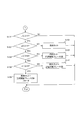
- FIG. 2 is a flow chart showing the operation of the vehicle speed control device according to the embodiment of the present disclosure.
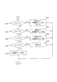
- FIG. 3 is a flow chart showing the operation of the vehicle speed control device according to the embodiment of the present disclosure.
- FIG. 4 is a flow chart showing the operation of the vehicle speed control device according to the embodiment of the present disclosure.
- FIG. 5 is a diagram showing the relationship between the engine rotation speed and the deceleration torque used in the vehicle speed control device according to the embodiment of the present disclosure.
- the vehicle speed control device 1 is composed of an electronic control device such as an ECU (Electronic Control Unit), and is mounted on a vehicle that transmits the driving force of an engine (not shown) to the drive wheels.
- ECU Electronic Control Unit
- the vehicle speed control device 1 includes a CPU (Central Processing Unit) 2, a memory 5, a fuel injection valve operating circuit 6, a compression / opening brake mechanism operating circuit 7, and a retarder operating circuit 8. ing.
- the CPU 2 includes a calculation unit 3 and a control unit 4.
- the arithmetic unit 3 and the control unit 4 are configured as functional blocks when the control program is executed in the CPU 2, but these may be configured as electric circuits, if necessary.
- the calculation unit 3 fired an electric signal according to the vehicle speed input from the vehicle speed sensor 11, a positioning signal received from the positioning satellite input from the positioning signal receiving unit 12, and around the vehicle input from the radar 13.
- the required deceleration torque (hereinafter, hereinafter, based on the electric signal according to the intensity of the reflected wave of the radio wave, the image signal of the image around the vehicle input from the camera 14, and the information stored in the memory 5). (Simply described as "deceleration torque”) is calculated.
- the control unit 4 calculates the engine speed based on the electric signal corresponding to the crank angle of the engine input from the crank angle sensor 15. Further, the control unit 4 calculates the rotation speed of the output shaft of the transmission based on the frequency of the pulse signal corresponding to the rotation of the output shaft of the transmission input from the pulse sensor (not shown). Further, the control unit 4 calculates the braking force of each auxiliary brake based on the engine rotation speed, the rotation speed of the output shaft of the transmission, and the like. The control unit 4 operates a control signal that operates an auxiliary brake selected from a plurality of auxiliary brakes mounted on the vehicle according to the calculated braking force of each auxiliary brake and the deceleration torque calculated by the calculation unit 3.
- the auxiliary brakes are an engine brake, a compression / release brake, and a retarder.
- the auxiliary brake is not limited to the above, and any brake that can be mounted on a vehicle such as an exhaust brake other than the main brake can be used.
- the memory 5 stores in advance a control program executed by the CPU 2 and three-dimensional map information including gradient information.
- the memory 5 stores a threshold value, which will be described later, used when operating each auxiliary brake.
- the fuel injection valve operating circuit 6 operates according to a control signal input from the control unit 4 to control the operation of the fuel injection valve 16.
- the compression release brake mechanism operation circuit 7 operates according to a control signal input from the control unit 4 to control the operation of the compression release brake mechanism 17.
- the retarder operation circuit 8 operates by a control signal input from the control unit 4 to control the operation of the retarder 18.
- the vehicle speed control device 1 repeats the operations shown in FIGS. 2 to 4 in a predetermined control cycle until the operation of stopping the vehicle speed control is performed.
- the calculation unit 3 of the CPU 2 calculates the current vehicle speed based on the electric signal input from the vehicle speed sensor 11 when traveling independently, sets the target vehicle speed, and sets the current vehicle speed and the target. calculates the target acceleration a t by PID (Proportional-Integral-Differential) control or the like by using the vehicle speed. Further, when the calculation unit 3 executes ACC (Adaptive Cruise Control; adaptive cruise control (constant speed traveling / inter-vehicle distance control)) to follow the vehicle in front and travels, various known devices are known. The target acceleration at is calculated using the logic (S001).
- PID Proportional-Integral-Differential
- ACC Adaptive Cruise Control
- adaptive cruise control constant speed traveling / inter-vehicle distance control
- the CPU When the ACC is performed, the CPU also functions as a follow-up state detection unit, which is a function unit for detecting whether or not the vehicle is following the preceding vehicle, for example, whether or not the vehicle is following the preceding vehicle.
- a vehicle capable of executing ACC is equipped with a sensor such as a camera or a millimeter-wave radar that detects the situation around the vehicle, and the CPU and these sensors are connected.
- the calculation unit 3 calculates the deceleration torque u (t) based on the various detected values input and the values stored in the memory 5 (S002).
- the calculation unit 3 calculates the deceleration torque u (t) using the equation (1).
- u (t) (rd / (i ⁇ ⁇ )) ⁇ (( ⁇ ⁇ S ⁇ V 2 ) + (m ⁇ g ⁇ ( ⁇ + sin ⁇ )) + ((m + ⁇ m) ⁇ at)) ⁇ ⁇ ⁇ (1)
- rd is the effective radius of the tire
- i is the total reduction ratio according to the shift stage
- ⁇ is the transmission efficiency
- ⁇ is the air resistance coefficient
- S is the front projected area of the vehicle
- V is the vehicle speed
- m is the vehicle.
- Weight g is gravity acceleration
- ⁇ rolling resistance coefficient
- ⁇ is the slope of the road surface
- ⁇ m is the inertial weight of the rotating part of the drive mechanism
- ⁇ ⁇ S ⁇ V 2 is the air resistance
- m ⁇ g ⁇ ⁇ is the rolling resistance
- m ⁇ g ⁇ sin ⁇ is the gradient resistance
- (m + ⁇ m) ⁇ at is the acceleration resistance.
- These air resistance, rolling resistance, gradient resistance and acceleration resistance are the running resistance of the vehicle.
- Each value of rd, i, ⁇ , ⁇ , S, ⁇ and ⁇ m in the equation (1) is stored in the memory 5 in advance.
- the calculation unit 3 calculates each value not stored in the memory 5 in the equation (1). Specifically, the calculation unit 3 calculates the vehicle speed V based on the electric signal input from the vehicle speed sensor 11. The calculation unit 3 calculates the current position based on the positioning signal input from the positioning signal receiving unit 12, and calculates the gradient ⁇ at the current position by referring to the three-dimensional map information stored in the memory 5. .. If the three-dimensional map information cannot be referred to, the gradient ⁇ is estimated using a signal or the like input from the acceleration sensor. The calculation unit 3 estimates the vehicle weight m using a known logic.
- the calculation unit 3 calculates the deceleration torque u (t) by the equation (1) using each value stored in the memory 5 and each value calculated and estimated by the above.
- control unit 4 calculates the braking force of each auxiliary brake by calculation (S003). Specifically, the control unit 4 calculates the engine speed and the rotation speed of the output shaft of the transmission, and S1 shown in FIG. 5 as the calculated engine speed and the braking force of each auxiliary brake at the transmission output shaft rotation speed. From S4, and from S11 to S14, the respective thresholds are calculated. Then, the control unit 4 stores each calculated threshold value in the memory 5.
- the threshold S11 has hysteresis in the deceleration torque decreasing direction with respect to the threshold S1
- the threshold S12 has hysteresis in the deceleration torque decreasing direction with respect to the threshold S2
- the threshold S13 becomes the threshold S3.
- the threshold value S14 has hysteresis in the decreasing direction of the deceleration torque
- the threshold value S14 has hysteresis in the decreasing direction of the deceleration torque with respect to the threshold value S4. Therefore, it is possible to prevent the auxiliary brake once activated or strengthened from immediately stopping or weakening.
- control unit 4 adjusts the width of hysteresis according to the state of following the vehicle in front of the vehicle. For example, when ACC is executed and the vehicle is traveling following the vehicle in front, the control unit 4 increases the width H of hysteresis as compared with the case where the vehicle is traveling without following the vehicle in front. As a result, when the vehicle is traveling following the vehicle in front, the behavior of the vehicle is unpredictable. It can be prevented from becoming stable.
- control unit 4 determines the downward slope of the road surface based on the positioning signal input from the positioning signal receiving unit 12 and the map information stored in the memory 5 when the vehicle is not traveling following the vehicle in front. When it is detected, the width H of the hysteresis is reduced as compared with the case where the downward gradient is not detected. As a result, it is possible to suppress the generation of unnecessary deceleration force.
- control unit 4 is not limited to the case where the hysteresis width H is changed according to the above conditions, and can change the hysteresis width H according to any condition other than the above.
- the control unit 4 determines whether or not the deceleration torque u (t) has changed relatively (S004).
- the deceleration torque u (t) changes relatively there are the following two cases. One is a case where the value of the deceleration torque u (t) calculated last time and the value of the deceleration torque u (t) calculated this time are different. The other is that the value of the deceleration torque u (t) calculated last time is equal to the value of the deceleration torque u (t) calculated this time, but the engine speed, the speed of the output shaft of the transmission, the road gradient, etc. This is a case where the braking force obtained by each auxiliary brake changes due to a change in the conditions of the vehicle and its surroundings.
- the control unit 4 ends the operation when there is no relative change in the deceleration torque u (t) (S004: NO).
- the control unit 4 determines whether or not the deceleration torque u (t) is relatively increased when there is a relative change in the deceleration torque u (t) (S004: YES) (S005). ..
- the deceleration torque u (t) increases relatively, there are the following two cases. One is a case where the value of the deceleration torque u (t) calculated this time is larger than the value of the deceleration torque u (t) calculated last time.
- the value of the deceleration torque u (t) calculated last time is equal to the value of the deceleration torque u (t) calculated this time, but the engine speed, the speed of the output shaft of the transmission, the road gradient, etc. This is a case where the braking force obtained by each auxiliary brake is reduced due to a change in the conditions of the vehicle and its surroundings.
- the control unit 4 determines whether or not the deceleration torque u (t) is equal to or greater than the threshold value S1 (S101).
- the deceleration torque u (t) when the deceleration torque u (t) is less than the threshold value S1 (S101: NO), the deceleration torque u (t) is relatively increased within the range of the region A shown in FIG. Since the state has changed from the state in which the auxiliary brake is not activated to the state in which it is not necessary to operate the auxiliary brake, the operation is terminated without controlling the operation of the auxiliary brake.
- the control unit 4 determines whether or not the deceleration torque u (t) is the threshold value S2 or more (S102).
- the control unit 4 applies the braking force of the engine brake because the deceleration torque u (t) is within the range of the region B shown in FIG.
- a control signal for stopping fuel injection (fuel cut) is output to the fuel injection valve operating circuit 6 (S103) in order to obtain the fuel, and then the operation is terminated.
- the control unit 4 determines whether or not the deceleration torque u (t) is the threshold value S3 or more (S104).
- the control unit 4 When the deceleration torque u (t) is less than the threshold value S3 (S104: NO), the control unit 4 has a deceleration torque u (t) within the range of the region C shown in FIG.
- a control signal for obtaining a weak braking force of the compression / release brake is output to the compression / release brake mechanism operating circuit 7 (S105), and then the operation is terminated.
- the braking force of the compression / release brake is set to 50%.
- the braking force of the compression release brake is not limited to 50%, and can be any value other than 0% and 100%.
- the control unit 4 determines whether or not the deceleration torque u (t) is the threshold value S4 or more (S106).
- the control unit 4 When the deceleration torque u (t) is less than the threshold value S4 (S106: NO), the control unit 4 has a deceleration torque u (t) within the range of the region D shown in FIG. A control signal for obtaining a strong braking force of the compression release brake is output to the compression release brake mechanism operating circuit 7 (S107), and then the operation is terminated.
- the braking force of the compression / release brake is set to 100%.
- the braking force of the compression / release brake is set to 100%, but also a brake stronger than the braking force when obtaining a weaker braking force of the compression / release brake If it is a force, it can be any value.
- the control unit 4 cuts and compresses the fuel because the deceleration torque u (t) is within the range of the region E shown in FIG.
- a control signal for obtaining the braking force of the retarder is output to the retarder operating circuit 8 (S108), and then the operation is terminated.
- control unit 4 determines whether or not the deceleration torque u (t) is less than the threshold value S14 when the deceleration torque u (t) is relatively reduced (S005: NO) (S201). ..
- the control unit 4 cuts fuel and cuts fuel because the deceleration torque u (t) is within the range of the region E shown in FIG.
- the strong braking force of the compression release brake and the braking force of the retarder are maintained (S202), and then the operation is terminated.
- the control unit 4 determines whether or not the deceleration torque u (t) is less than the threshold value S13 (S203).
- the control unit 4 cuts the fuel and cuts the fuel because the deceleration torque u (t) is within the range D shown in FIG.
- the strong braking force of the compression release brake is maintained (S204), and then the operation is terminated.
- the control unit 4 determines whether or not the deceleration torque u (t) is less than the threshold value S12 (S205).
- the control unit 4 cuts the fuel and cuts the fuel because the deceleration torque u (t) is within the range of the region C shown in FIG.
- the weak braking force of the compression release brake is maintained (S206), and then the operation is terminated.
- the control unit 4 determines whether or not the deceleration torque u (t) is less than the threshold value S11 (S207).
- the control unit 4 cuts the fuel because the deceleration torque u (t) is within the range of the region B shown in FIG. 5 (S208). ), And then end the operation.
- the control unit 4 has all the auxiliary brakes because the deceleration torque u (t) is within the range of the region A shown in FIG. Stops the operation (S209), and then ends the operation.
- the required deceleration torque is calculated based on the running resistance of the vehicle, and the auxiliary brake selected from the plurality of auxiliary brakes is operated according to the deceleration torque.
- the vehicle speed control device is suitable for controlling the vehicle speed of a vehicle provided with a plurality of auxiliary brakes.
- Vehicle speed control device 1
- CPU 3 Calculation unit 4
- Memory 6
- Fuel injection valve operation circuit 7
- Compression release brake mechanism operation circuit 8
- Retarder operation circuit 11
- Vehicle speed sensor 12 Positioning signal receiver 13 Radar 14
- Camera 15
- Crank angle sensor 16 Fuel injection valve 17 Compression release brake mechanism 18 retarder
Landscapes
- Engineering & Computer Science (AREA)
- Mechanical Engineering (AREA)
- Transportation (AREA)
- Chemical & Material Sciences (AREA)
- Combustion & Propulsion (AREA)
- General Engineering & Computer Science (AREA)
- Automation & Control Theory (AREA)
- Regulating Braking Force (AREA)
- Control Of Vehicle Engines Or Engines For Specific Uses (AREA)
- Control Of Driving Devices And Active Controlling Of Vehicle (AREA)
- Output Control And Ontrol Of Special Type Engine (AREA)
Abstract
実際の車速を目標車速に一致させ易くすることにより、運転のフィーリングを良好にすると共に、下り勾配において主ブレーキの使用を抑制する車速制御装置。複数の補助ブレーキを備える車両の車速を制御する車速制御装置は、車両の走行抵抗に基づいて必要な減速トルクを演算する演算部と、減速トルクに応じて複数の補助ブレーキの中から作動させる補助ブレーキを選択し、選択した補助ブレーキを作動させる制御部と、を有する。
Description
本発明は、複数の補助ブレーキを備える車両の車速を制御する車速制御装置に関する。
従来、設定された車速からの逸脱上限値を設け、車速がこの逸脱上限値を上回った場合に補助ブレーキを作動させる制御装置が知られている。
特許文献1は、車両運転状態に応じて減速トルクの目標値を算出し、算出した目標値に応じてバルブ駆動機構の駆動を制御することにより、車両運転状況に応じた適切なエンジンブレーキを作動させる制御装置を開示している。
しかしながら、従来の制御装置は、主に下り勾配等で補助ブレーキが適切に作動しないことにより、設定された車速から大きく逸脱したり車速のハンチングが発生したりするため、運転のフィーリングが悪いという課題を有する。
本開示の目的は、実際の車速を目標車速に一致させ易くすることにより、運転のフィーリングを良好にすることができると共に、下り勾配において主ブレーキの使用を抑制することができる車速制御装置を提供することである。
本開示の一態様に係る車速制御装置は、複数の補助ブレーキを備える車両の車速を制御する車速制御装置であって、前記車両の走行抵抗に基づいて必要な減速トルクを演算する演算部と、前記減速トルクに応じて前記複数の補助ブレーキの中から作動させる補助ブレーキを選択し、選択した補助ブレーキを作動させる制御部と、を有する。
本開示によれば、実際の車速を目標車速に一致させ易くすることにより、運転のフィーリングを良好にすることができると共に、下り勾配において主ブレーキの使用を抑制することができる。
以下、図面を適宜参照して、本開示の実施の形態につき、詳細に説明する。
<車速制御装置の構成>
本開示の実施の形態に係る車速制御装置1の構成につき、図1を参照しながら、以下に詳細に説明する。
本開示の実施の形態に係る車速制御装置1の構成につき、図1を参照しながら、以下に詳細に説明する。
車速制御装置1は、ECU(Electronic Control Unit)等の電子制御装置によって構成され、図示を省略するエンジンの駆動力を駆動輪に伝達する車両に搭載されている。
具体的には、車速制御装置1は、CPU(Central Processing Unit)2と、メモリ5と、燃料噴射弁作動回路6と、圧縮開放ブレーキ機構作動回路7と、リターダ作動回路8と、を有している。CPU2は、演算部3と、制御部4と、を備えている。演算部3と、制御部4と、はCPU2における制御プログラム実行時の機能ブロックとして構成されるが、これらは、必要に応じて、電気回路として構成されてもよい。
演算部3は、車速センサ11から入力される車両の車速に応じた電気信号、測位信号受信部12から入力される測位衛星から受信した測位信号、レーダ13から入力される車両の周囲に発射した電波の反射波の強度に応じた電気信号、及びカメラ14から入力される車両の周囲の画像の画像信号と、メモリ5に記憶されている情報と、に基づいて、必要な減速トルク(以下、単に「減速トルク」と記載する)を算出する。
制御部4は、クランク角センサ15から入力されるエンジンのクランク角に応じた電気信号に基づいて、エンジン回転数を算出する。また、制御部4は、図示しないパルスセンサから入力されるトランスミッションのアウトプットシャフトの回転に応じたパルス信号の周波数に基づいてトランスミッションのアウトプットシャフトの回転数を算出する。また、制御部4は、エンジン回転数及びトランスミッションのアウトプットシャフトの回転数等に基づいて、各補助ブレーキのブレーキ力を算出する。制御部4は、算出した各補助ブレーキのブレーキ力と、演算部3により算出された減速トルクと、に応じて、車両が搭載する複数の補助ブレーキの中から選択した補助ブレーキを作動させる制御信号を、燃料噴射弁作動回路6、圧縮開放ブレーキ機構作動回路7又はリターダ作動回路8に出力する。ここで、補助ブレーキは、エンジンブレーキ、圧縮開放ブレーキ及びリターダである。なお、補助ブレーキとしては、上記に限らず、主ブレーキ以外の排気ブレーキ等の車両に搭載可能な任意のブレーキを用いることができる。
メモリ5は、CPU2によって実行される制御プログラム、及び勾配情報を含む三次元の地図情報を予め記憶している。メモリ5は、各補助ブレーキを作動させる際に使用される後述の閾値を記憶する。
燃料噴射弁作動回路6は、制御部4から入力される制御信号により動作して燃料噴射弁16の作動を制御する。
圧縮開放ブレーキ機構作動回路7は、制御部4から入力される制御信号により動作して圧縮開放ブレーキ機構17の作動を制御する。
リターダ作動回路8は、制御部4から入力される制御信号により動作してリターダ18の作動を制御する。
<車速制御装置の動作>
本開示の実施の形態に係る車速制御装置1の動作につき、図1から図4を参照しながら、以下に詳細に説明する。
本開示の実施の形態に係る車速制御装置1の動作につき、図1から図4を参照しながら、以下に詳細に説明する。
車速制御装置1は、車速制御を停止させる操作がなされるまで、図2から図4に示す動作を所定の制御周期で繰り返し行う。
まず、CPU2の演算部3は、単独で走行している場合には、車速センサ11から入力される電気信号に基づいて現在の車速を算出し、目標車速を設定すると共に、現在の車速と目標車速とを用いてPID(Proportional-Integral-Differential)制御等によって目標加速度atを算出する。また、演算部3は、ACC(Adaptive Cruise Control;アダプティブ・クルーズ・コントロール(定速走行・車間距離制御))を実行して前方車両に追従して走行している場合には、公知の種々のロジックを用いて目標加速度atを算出する(S001)。ACCが行われる際、CPUは、車両の先行車への追従状態、例えば、車両が先行車に追従しているか否かを検出する機能部である追従状態検出部としても機能する。なお、ACCを実行可能な車両がカメラ又はミリ波レーダ等の、車両の周辺の状況を検出するセンサを搭載し、CPUとこれらセンサが接続されていることは言うまでも無い。
次に、演算部3は、入力される各種検出値及びメモリ5に記憶されている値に基づいて、減速トルクu(t)を計算により算出する(S002)。
具体的には、演算部3は、(1)式を用いて、減速トルクu(t)を算出する。
u(t)=(rd/(i×η))×((λ×S×V2)+(m×g×(μ+sinθ))+((m+Δm)×at))・・・(1)
(1)式において、rdはタイヤの有効半径、iは変速段に応じた総減速比、ηは伝達効率、λは空気抵抗係数、Sは車両の前面投影面積、Vは車速、mは車重、gは重力加速度、μは転がり抵抗係数、θは路面の勾配、Δmは駆動機構回転部の慣性重量及びatは目標加速度である。
(1)式において、λ×S×V2は空気抵抗、m×g×μは転がり抵抗、m×g×sinθは勾配抵抗、及び(m+Δm)×atは加速抵抗である。これらの空気抵抗、転がり抵抗、勾配抵抗及び加速抵抗は、車両の走行抵抗となる。(1)式におけるrd、i、η、λ、S、μ及びΔmの各値は、メモリ5に予め記憶されている。
また、演算部3は、(1)式におけるメモリ5に記憶されていない各値を算出する。具体的には、演算部3は、車速センサ11から入力される電気信号に基づいて車速Vを算出する。演算部3は、測位信号受信部12から入力される測位信号に基づいて現在位置を算出し、メモリ5に記憶されている3次元の地図情報を参照して、現在位置における勾配θを算出する。3次元の地図情報を参照できない場合は、加速度センサから入力される信号等を用いて勾配θを推定する。演算部3は、公知のロジックを用いて車重mを推定する。
演算部3は、上記のメモリ5に記憶されている各値と、上記により算出及び推定した各値とを用いて、(1)式により減速トルクu(t)を算出する。
次に、制御部4は、各補助ブレーキのブレーキ力を計算により算出する(S003)。具体的には、制御部4は、エンジン回転数およびトランスミッションのアウトプットシャフトの回転数を算出し、算出したエンジン回転数および、トランスミッションアウトプットシャフト回転数における各補助ブレーキのブレーキ力として図5に示すS1からS4、及び、S11からS14の各閾値を算出する。そして、制御部4は、算出した各閾値をメモリ5に記憶する。
ここで、閾値S11は、閾値S1に対して減速トルクの低下方向にヒステリシスを有し、閾値S12は、閾値S2に対して減速トルクの低下方向にヒステリシスを有し、閾値S13は、閾値S3に対して減速トルクの低下方向にヒステリシスを有し、閾値S14は、閾値S4に対して減速トルクの低下方向にヒステリシスを有している。よって、一度作動した又は強まった補助ブレーキが、すぐに作動を停止するまたは弱まることを防止できる。
また、制御部4は、車両の先行車への追従状態に応じて、ヒステリシスの幅を調整する。例えば、ACCを実行して前方車両に追従して走行している場合には、前方車両に追従しないで走行している場合に比べて、制御部4はヒステリシスの幅Hを大きくする。これにより、前方車両に追従して走行している場合に、挙動が予測できない前方車両の車速の影響を受けて補助ブレーキを作動する場合と作動しない場合とが繰り返されることによる車両の挙動が不安定になることを防ぐことができる。
更に、制御部4は、前方車両に追従して走行していない場合において、測位信号受信部12から入力される測位信号とメモリ5に記憶されている地図情報とに基づいて路面の下り勾配を検出した際に、下り勾配を検出しない場合に比べて、ヒステリシスの幅Hを小さくする。これにより、不要な減速力の発生を抑制することが出来る。
なお、制御部4は、上記の条件に応じてヒステリシスの幅Hを変化させる場合に限らず、上記以外の任意の条件に応じてヒステリシスの幅Hを変化させることができる。
次に、制御部4は、減速トルクu(t)が相対的に変化したか否かを判定する(S004)。減速トルクu(t)が相対的に変化する場合には、以下の2つの場合がある。1つは、前回算出した減速トルクu(t)の値と、今回算出した減速トルクu(t)の値とが異なる場合である。もう1つは、前回算出した減速トルクu(t)の値と、今回算出した減速トルクu(t)の値とが等しいものの、エンジン回転数、トランスミッションのアウトプットシャフトの回転数、道路勾配等、車両及びその周辺の条件が変化したことにより、各補助ブレーキによって得られるブレーキ力が変化した場合である。
制御部4は、減速トルクu(t)に相対的な変化が無い場合に(S004:NO)、動作を終了する。
一方、制御部4は、減速トルクu(t)に相対的な変化が有る場合に(S004:YES)、減速トルクu(t)が相対的に増加しているか否かを判定する(S005)。減速トルクu(t)が相対的に増加する場合には、以下の2つの場合がある。1つは、前回算出した減速トルクu(t)の値よりも、今回算出した減速トルクu(t)の値の方が大きい場合である。もう1つは、前回算出した減速トルクu(t)の値と、今回算出した減速トルクu(t)の値とが等しいものの、エンジン回転数、トランスミッションのアウトプットシャフトの回転数、道路勾配等、車両及びその周辺の条件が変化したことにより、各補助ブレーキによって得られるブレーキ力が低下した場合である。
減速トルクu(t)が相対的に増加している場合(S005:YES)、制御部4は、減速トルクu(t)が閾値S1以上であるか否かを判定する(S101)。
制御部4は、減速トルクu(t)が閾値S1未満の場合に(S101:NO)、図5に示す領域Aの範囲内で減速トルクu(t)が相対的に増加したものであり、補助ブレーキを作動していない状態から補助ブレーキを作動させる必要の無い状態へ変化したものであるため、補助ブレーキを作動させる制御を行なわずに動作を終了する。
一方、制御部4は、減速トルクu(t)が閾値S1以上の場合に(S101:YES)、減速トルクu(t)が閾値S2以上であるか否かを判定する(S102)。
制御部4は、減速トルクu(t)が閾値S2未満の場合に(S102:NO)、減速トルクu(t)が図5に示す領域Bの範囲内であるため、エンジンブレーキの制動力を得るために燃料の噴射を停止(燃料カット)する制御信号を燃料噴射弁作動回路6に出力して(S103)、その後に動作を終了する。
一方、制御部4は、減速トルクu(t)が閾値S2以上の場合に(S102:YES)、減速トルクu(t)が閾値S3以上であるか否かを判定する(S104)。
制御部4は、減速トルクu(t)が閾値S3未満の場合に(S104:NO)、減速トルクu(t)が図5に示す領域Cの範囲内であるため、燃料カットに加えて、圧縮開放ブレーキの弱めの制動力を得るための制御信号を圧縮開放ブレーキ機構作動回路7に出力して(S105)、その後に動作を終了する。ここで、圧縮開放ブレーキの弱めの制動力を得るためには、例えば圧縮開放ブレーキの最大ブレーキ力を100%とした場合において、圧縮開放ブレーキのブレーキ力を50%にする。なお、圧縮開放ブレーキの弱めの制動力を得るためには、圧縮開放ブレーキのブレーキ力を50%にする場合に限らず0%及び100%以外の任意の値にすることができる。
一方、制御部4は、減速トルクu(t)が閾値S3以上の場合に(S104:YES)、減速トルクu(t)が閾値S4以上であるか否かを判定する(S106)。
制御部4は、減速トルクu(t)が閾値S4未満の場合に(S106:NO)、減速トルクu(t)が図5に示す領域Dの範囲内であるため、燃料カットに加えて、圧縮開放ブレーキの強めの制動力を得るための制御信号を圧縮開放ブレーキ機構作動回路7に出力して(S107)、その後に動作を終了する。ここで、圧縮開放ブレーキの強めの制動力を得るためには、例えば圧縮開放ブレーキの最大ブレーキ力を100%とした場合に圧縮開放ブレーキのブレーキ力を100%にする。なお、圧縮開放ブレーキの強めの制動力を得るためには、圧縮開放ブレーキのブレーキ力を100%にする場合に限らず、圧縮開放ブレーキの弱めの制動力を得る場合のブレーキ力よりも強いブレーキ力であれば任意の値にすることができる。
一方、制御部4は、減速トルクu(t)が閾値S4以上の場合に(S106:YES)、減速トルクu(t)が図5に示す領域Eの範囲内であるため、燃料カット及び圧縮開放ブレーキの強めの制動力に加えて、リターダの制動力を得るための制御信号をリターダ作動回路8に出力して(S108)、その後に動作を終了する。
また、制御部4は、減速トルクu(t)が相対的に減少している場合に(S005:NO)、減速トルクu(t)が閾値S14未満であるか否かを判定する(S201)。
制御部4は、減速トルクu(t)が閾値S14以上の場合に(S201:NO)、減速トルクu(t)が図5に示す領域Eの範囲内であるため、燃料カットを行うと共に、圧縮開放ブレーキの強めの制動力及びリターダの制動力を保持し(S202)、その後に動作を終了する。
一方、制御部4は、減速トルクu(t)が閾値S14未満の場合に(S201:YES)、減速トルクu(t)が閾値S13未満であるか否かを判定する(S203)。
制御部4は、減速トルクu(t)が閾値S13以上の場合に(S203:NO)、減速トルクu(t)が図5に示す領域Dの範囲内であるため、燃料カットを行うと共に、圧縮開放ブレーキの強めの制動力を保持し(S204)、その後に動作を終了する。
一方、制御部4は、減速トルクu(t)が閾値S13未満の場合に(S203:YES)、減速トルクu(t)が閾値S12未満であるか否かを判定する(S205)。
制御部4は、減速トルクu(t)が閾値S12以上の場合に(S205:NO)、減速トルクu(t)が図5に示す領域Cの範囲内であるため、燃料カットを行うと共に、圧縮開放ブレーキの弱めの制動力を保持し(S206)、その後に動作を終了する。
一方、制御部4は、減速トルクu(t)が閾値S12未満の場合に(S205:YES)、減速トルクu(t)が閾値S11未満であるか否かを判定する(S207)。
制御部4は、減速トルクu(t)が閾値S11以上の場合に(S207:NO)、減速トルクu(t)が図5に示す領域Bの範囲内であるため、燃料カットを行い(S208)、その後に動作を終了する。
一方、制御部4は、減速トルクu(t)が閾値S11未満の場合に(S207:YES)、減速トルクu(t)が図5に示す領域Aの範囲内であるため、全ての補助ブレーキの作動を停止し(S209)、その後に動作を終了する。
このように、本実施の形態によれば、車両の走行抵抗に基づいて必要な減速トルクを演算し、減速トルクに応じて複数の補助ブレーキの中から選択した補助ブレーキを作動させることにより、実際の車速を目標車速に一致させ易くすることにより、運転のフィーリングを良好にすることができると共に、下り勾配において主ブレーキの使用を抑制することができる。
なお、本開示は、部材の種類、配置、個数等は前述の実施の形態に限定されるものではなく、その構成要素を同等の作用効果を奏するものに適宜置換する等、開示の要旨を逸脱しない範囲で適宜変更可能であることはもちろんである。
本出願は、2019年3月27日付で出願された日本国特許出願(特願2019-061594)に基づくものであり、その内容はここに参照として取り込まれる。
本発明に係る車速制御装置は、複数の補助ブレーキを備える車両の車速を制御するのに好適である。
1 車速制御装置
2 CPU
3 演算部
4 制御部
5 メモリ
6 燃料噴射弁作動回路
7 圧縮開放ブレーキ機構作動回路
8 リターダ作動回路
11 車速センサ
12 測位信号受信部
13 レーダ
14 カメラ
15 クランク角センサ
16 燃料噴射弁
17 圧縮開放ブレーキ機構
18 リターダ
2 CPU
3 演算部
4 制御部
5 メモリ
6 燃料噴射弁作動回路
7 圧縮開放ブレーキ機構作動回路
8 リターダ作動回路
11 車速センサ
12 測位信号受信部
13 レーダ
14 カメラ
15 クランク角センサ
16 燃料噴射弁
17 圧縮開放ブレーキ機構
18 リターダ
Claims (5)
- 複数の補助ブレーキを備える車両の車速を制御する車速制御装置であって、
前記車両の走行抵抗に基づいて必要な減速トルクを演算する演算部と、
前記減速トルクに応じて前記複数の補助ブレーキの中から作動させる補助ブレーキを選択し、選択した補助ブレーキを作動させる制御部と、
を有する車速制御装置。 - 前記制御部は、前記減速トルクにヒステリシスを設けて、前記複数の補助ブレーキの中から作動させる補助ブレーキを選択する、
請求項1に記載の車速制御装置。 - 前記車両の先行車への追従状態を検出する追従状態検出部をさらに有し、
前記制御部は、前記車両の先行車への追従状態に応じて前記ヒステリシスの幅を調整する、
請求項2に記載の車速制御装置。 - 前記制御部は、前記車両が前記先行車に追従している場合には、前記先行車に追従していない場合に比べて、前記ヒステリシスの幅を大きくする、
請求項3に記載の車速制御装置。 - 前記制御部は、前記先行車に追従していない場合において、路面の下り勾配を検出した場合には、前記路面の下り勾配を検出しない場合に比べて、前記ヒステリシスの幅を小さくする、
請求項3に記載の車速制御装置。
Priority Applications (3)
| Application Number | Priority Date | Filing Date | Title |
|---|---|---|---|
| US17/442,607 US12017650B2 (en) | 2019-03-27 | 2020-03-23 | Vehicle speed control device |
| CN202080022583.1A CN113631451B (zh) | 2019-03-27 | 2020-03-23 | 车速控制装置 |
| DE112020001462.2T DE112020001462T5 (de) | 2019-03-27 | 2020-03-23 | Fahrzeuggeschwindigkeitssteuervorrichtung |
Applications Claiming Priority (2)
| Application Number | Priority Date | Filing Date | Title |
|---|---|---|---|
| JP2019-061594 | 2019-03-27 | ||
| JP2019061594A JP2020159326A (ja) | 2019-03-27 | 2019-03-27 | 車速制御装置 |
Publications (1)
| Publication Number | Publication Date |
|---|---|
| WO2020196358A1 true WO2020196358A1 (ja) | 2020-10-01 |
Family
ID=72610927
Family Applications (1)
| Application Number | Title | Priority Date | Filing Date |
|---|---|---|---|
| PCT/JP2020/012584 Ceased WO2020196358A1 (ja) | 2019-03-27 | 2020-03-23 | 車速制御装置 |
Country Status (5)
| Country | Link |
|---|---|
| US (1) | US12017650B2 (ja) |
| JP (1) | JP2020159326A (ja) |
| CN (1) | CN113631451B (ja) |
| DE (1) | DE112020001462T5 (ja) |
| WO (1) | WO2020196358A1 (ja) |
Families Citing this family (3)
| Publication number | Priority date | Publication date | Assignee | Title |
|---|---|---|---|---|
| FR3116497B1 (fr) * | 2020-11-23 | 2024-02-16 | Foundation Brakes France | Procédé de commande du couple de serrage d’un frein électromécanique amélioré |
| US20240043002A1 (en) * | 2022-08-03 | 2024-02-08 | International Engine Intellectual Property Company, Llc | Systems and methods for managing vehicle following distance using engine braking |
| DE102023204036A1 (de) * | 2023-05-02 | 2024-11-07 | Volkswagen Aktiengesellschaft | Verfahren und Fahrerassistenzvorrichtung zum Ausführen wenigstens einer Fahrerassistenzfunktion zur Unterstützung eines Fahrers bei Bergabfahrten |
Citations (8)
| Publication number | Priority date | Publication date | Assignee | Title |
|---|---|---|---|---|
| JPH0891188A (ja) * | 1994-09-26 | 1996-04-09 | Nissan Diesel Motor Co Ltd | 車両の補助ブレーキ制御装置 |
| JPH11321606A (ja) * | 1998-05-20 | 1999-11-24 | Hino Motors Ltd | ブレーキシステム |
| JP2003341494A (ja) * | 2002-05-23 | 2003-12-03 | Hino Motors Ltd | ブレーキ連動制御装置 |
| JP2008279924A (ja) * | 2007-05-11 | 2008-11-20 | Hino Motors Ltd | 補助ブレーキ制御装置 |
| JP2009149173A (ja) * | 2007-12-19 | 2009-07-09 | Mitsubishi Fuso Truck & Bus Corp | オートクルーズ装置 |
| US20140316669A1 (en) * | 2011-10-31 | 2014-10-23 | Scania Cv Ab | Device and method for controlling braking of a motor vehicle |
| JP2015000605A (ja) * | 2013-06-13 | 2015-01-05 | いすゞ自動車株式会社 | ハイブリッド車両及びその制御方法 |
| JP2017520452A (ja) * | 2014-06-24 | 2017-07-27 | ボルボトラックコーポレーション | 車両のクルーズコントロールブレーキを支援する機構および方法 |
Family Cites Families (14)
| Publication number | Priority date | Publication date | Assignee | Title |
|---|---|---|---|---|
| JPS6476733A (en) | 1987-09-17 | 1989-03-22 | Nec Corp | Wire bonding method for ic |
| JP2572402B2 (ja) | 1987-10-23 | 1997-01-16 | 日本電信電話株式会社 | 光ファイバ回線のアクセス方法及びそのコネクタプラグ |
| JPH1120496A (ja) * | 1997-06-27 | 1999-01-26 | Denso Corp | オートクルーズ制御装置 |
| JPH11301308A (ja) | 1998-04-17 | 1999-11-02 | Nissan Diesel Motor Co Ltd | オートクルーズ装置 |
| DE19920096B4 (de) * | 1999-05-03 | 2004-05-27 | Bayerische Motoren Werke Ag | Vorrichtung zur Bremslichtansteuerung |
| JP2003176733A (ja) | 2001-12-11 | 2003-06-27 | Denso Corp | 車両のエンジンブレーキ制御装置 |
| DE10231360A1 (de) * | 2002-07-11 | 2004-01-22 | Robert Bosch Gmbh | Verfahren zur Regelung der Geschwindigkeit eines Fahrzeugs |
| JP2007253715A (ja) | 2006-03-22 | 2007-10-04 | Fujitsu Ten Ltd | 車両制御装置および車両制御方法 |
| JP2008239002A (ja) * | 2007-03-28 | 2008-10-09 | Mitsubishi Fuso Truck & Bus Corp | 車両の定速走行装置 |
| JP5177627B2 (ja) | 2007-07-30 | 2013-04-03 | Udトラックス株式会社 | 自動省燃費運転システム |
| JP2010234987A (ja) | 2009-03-31 | 2010-10-21 | Mitsubishi Fuso Truck & Bus Corp | オートクルーズ制御方法と装置 |
| DE112011105109T5 (de) * | 2011-03-30 | 2014-01-16 | Toyota Jidosha Kabushiki Kaisha | Fahrzeugsteuerungsvorrichtung |
| JP2015058926A (ja) | 2013-09-20 | 2015-03-30 | いすゞ自動車株式会社 | ハイブリッド車両、及びその制御方法 |
| JP7046546B2 (ja) | 2017-09-28 | 2022-04-04 | 株式会社野村総合研究所 | 会議支援システムおよび会議支援プログラム |
-
2019
- 2019-03-27 JP JP2019061594A patent/JP2020159326A/ja active Pending
-
2020
- 2020-03-23 CN CN202080022583.1A patent/CN113631451B/zh active Active
- 2020-03-23 WO PCT/JP2020/012584 patent/WO2020196358A1/ja not_active Ceased
- 2020-03-23 DE DE112020001462.2T patent/DE112020001462T5/de active Pending
- 2020-03-23 US US17/442,607 patent/US12017650B2/en active Active
Patent Citations (8)
| Publication number | Priority date | Publication date | Assignee | Title |
|---|---|---|---|---|
| JPH0891188A (ja) * | 1994-09-26 | 1996-04-09 | Nissan Diesel Motor Co Ltd | 車両の補助ブレーキ制御装置 |
| JPH11321606A (ja) * | 1998-05-20 | 1999-11-24 | Hino Motors Ltd | ブレーキシステム |
| JP2003341494A (ja) * | 2002-05-23 | 2003-12-03 | Hino Motors Ltd | ブレーキ連動制御装置 |
| JP2008279924A (ja) * | 2007-05-11 | 2008-11-20 | Hino Motors Ltd | 補助ブレーキ制御装置 |
| JP2009149173A (ja) * | 2007-12-19 | 2009-07-09 | Mitsubishi Fuso Truck & Bus Corp | オートクルーズ装置 |
| US20140316669A1 (en) * | 2011-10-31 | 2014-10-23 | Scania Cv Ab | Device and method for controlling braking of a motor vehicle |
| JP2015000605A (ja) * | 2013-06-13 | 2015-01-05 | いすゞ自動車株式会社 | ハイブリッド車両及びその制御方法 |
| JP2017520452A (ja) * | 2014-06-24 | 2017-07-27 | ボルボトラックコーポレーション | 車両のクルーズコントロールブレーキを支援する機構および方法 |
Also Published As
| Publication number | Publication date |
|---|---|
| CN113631451B (zh) | 2024-04-26 |
| US12017650B2 (en) | 2024-06-25 |
| JP2020159326A (ja) | 2020-10-01 |
| CN113631451A (zh) | 2021-11-09 |
| DE112020001462T5 (de) | 2021-12-09 |
| US20220169248A1 (en) | 2022-06-02 |
Similar Documents
| Publication | Publication Date | Title |
|---|---|---|
| CN101998913B (zh) | 追随距离控制装置和追随距离控制方法 | |
| US20160016469A1 (en) | Vehicle travel control apparatus | |
| JP3646660B2 (ja) | 車両用追従走行制御装置 | |
| US10000211B2 (en) | Vehicle travel control apparatus | |
| CN104724103B (zh) | 交通工具间控制设备和交通工具间控制方法 | |
| US9630621B2 (en) | Automatic drive control method for vehicle | |
| JP6246382B2 (ja) | 車両用制御システム | |
| US20090118958A1 (en) | Vehicle travel control device and vehicle travel control method | |
| CN113631451B (zh) | 车速控制装置 | |
| JP6720812B2 (ja) | 車両用運転支援装置 | |
| EP3144198B1 (en) | Control apparatus of vehicle | |
| JP6014185B2 (ja) | 車両走行制御装置、車両走行制御方法、および車両走行制御プログラム | |
| EP2937254B1 (en) | Vehicle control apparatus | |
| US20200384995A1 (en) | Speed controller for platooning vehicle and method therefor | |
| US7359788B2 (en) | Apparatus for controlling distance between vehicles | |
| CN111542464A (zh) | 车辆控制方法及车辆控制装置 | |
| CN110382322B (zh) | 行驶控制装置、车辆及行驶控制方法 | |
| CN110446643B (zh) | 行驶控制装置、车辆及行驶控制方法 | |
| JP4613124B2 (ja) | ナビ協調走行制御装置 | |
| JP2019034633A (ja) | 走行制御装置、車両および走行制御方法 | |
| JP7824577B2 (ja) | 車両の制御装置 | |
| JP2018154231A (ja) | 衝突緩和装置 | |
| JP4649279B2 (ja) | 車両のブレーキ制御装置 | |
| JP2014134156A (ja) | ブレーキ制御装置 | |
| JP7471248B2 (ja) | 車両制御装置および車両制御方法 |
Legal Events
| Date | Code | Title | Description |
|---|---|---|---|
| 121 | Ep: the epo has been informed by wipo that ep was designated in this application |
Ref document number: 20779942 Country of ref document: EP Kind code of ref document: A1 |
|
| 122 | Ep: pct application non-entry in european phase |
Ref document number: 20779942 Country of ref document: EP Kind code of ref document: A1 |