WO2020196048A1 - 複合ケーブル - Google Patents
複合ケーブル Download PDFInfo
- Publication number
- WO2020196048A1 WO2020196048A1 PCT/JP2020/011518 JP2020011518W WO2020196048A1 WO 2020196048 A1 WO2020196048 A1 WO 2020196048A1 JP 2020011518 W JP2020011518 W JP 2020011518W WO 2020196048 A1 WO2020196048 A1 WO 2020196048A1
- Authority
- WO
- WIPO (PCT)
- Prior art keywords
- composite cable
- resin
- sheath
- silane
- resin composition
- Prior art date
- Legal status (The legal status is an assumption and is not a legal conclusion. Google has not performed a legal analysis and makes no representation as to the accuracy of the status listed.)
- Ceased
Links
Images

Classifications
-
- H—ELECTRICITY
- H01—ELECTRIC ELEMENTS
- H01B—CABLES; CONDUCTORS; INSULATORS; SELECTION OF MATERIALS FOR THEIR CONDUCTIVE, INSULATING OR DIELECTRIC PROPERTIES
- H01B7/00—Insulated conductors or cables characterised by their form
- H01B7/17—Protection against damage caused by external factors, e.g. sheaths or armouring
- H01B7/18—Protection against damage caused by wear, mechanical force or pressure; Sheaths; Armouring
-
- H—ELECTRICITY
- H01—ELECTRIC ELEMENTS
- H01B—CABLES; CONDUCTORS; INSULATORS; SELECTION OF MATERIALS FOR THEIR CONDUCTIVE, INSULATING OR DIELECTRIC PROPERTIES
- H01B3/00—Insulators or insulating bodies characterised by the insulating materials; Selection of materials for their insulating or dielectric properties
- H01B3/18—Insulators or insulating bodies characterised by the insulating materials; Selection of materials for their insulating or dielectric properties mainly consisting of organic substances
- H01B3/20—Insulators or insulating bodies characterised by the insulating materials; Selection of materials for their insulating or dielectric properties mainly consisting of organic substances liquids, e.g. oils
- H01B3/22—Insulators or insulating bodies characterised by the insulating materials; Selection of materials for their insulating or dielectric properties mainly consisting of organic substances liquids, e.g. oils hydrocarbons
-
- H—ELECTRICITY
- H01—ELECTRIC ELEMENTS
- H01B—CABLES; CONDUCTORS; INSULATORS; SELECTION OF MATERIALS FOR THEIR CONDUCTIVE, INSULATING OR DIELECTRIC PROPERTIES
- H01B3/00—Insulators or insulating bodies characterised by the insulating materials; Selection of materials for their insulating or dielectric properties
- H01B3/18—Insulators or insulating bodies characterised by the insulating materials; Selection of materials for their insulating or dielectric properties mainly consisting of organic substances
- H01B3/28—Insulators or insulating bodies characterised by the insulating materials; Selection of materials for their insulating or dielectric properties mainly consisting of organic substances natural or synthetic rubbers
-
- B—PERFORMING OPERATIONS; TRANSPORTING
- B29—WORKING OF PLASTICS; WORKING OF SUBSTANCES IN A PLASTIC STATE IN GENERAL
- B29C—SHAPING OR JOINING OF PLASTICS; SHAPING OF MATERIAL IN A PLASTIC STATE, NOT OTHERWISE PROVIDED FOR; AFTER-TREATMENT OF THE SHAPED PRODUCTS, e.g. REPAIRING
- B29C48/00—Extrusion moulding, i.e. expressing the moulding material through a die or nozzle which imparts the desired form; Apparatus therefor
- B29C48/15—Extrusion moulding, i.e. expressing the moulding material through a die or nozzle which imparts the desired form; Apparatus therefor incorporating preformed parts or layers, e.g. extrusion moulding around inserts
- B29C48/154—Coating solid articles, i.e. non-hollow articles
-
- B—PERFORMING OPERATIONS; TRANSPORTING
- B29—WORKING OF PLASTICS; WORKING OF SUBSTANCES IN A PLASTIC STATE IN GENERAL
- B29K—INDEXING SCHEME ASSOCIATED WITH SUBCLASSES B29B, B29C OR B29D, RELATING TO MOULDING MATERIALS OR TO MATERIALS FOR MOULDS, REINFORCEMENTS, FILLERS OR PREFORMED PARTS, e.g. INSERTS
- B29K2019/00—Use of rubber not provided for in a single one of main groups B29K2007/00 - B29K2011/00, as moulding material
-
- B—PERFORMING OPERATIONS; TRANSPORTING
- B29—WORKING OF PLASTICS; WORKING OF SUBSTANCES IN A PLASTIC STATE IN GENERAL
- B29K—INDEXING SCHEME ASSOCIATED WITH SUBCLASSES B29B, B29C OR B29D, RELATING TO MOULDING MATERIALS OR TO MATERIALS FOR MOULDS, REINFORCEMENTS, FILLERS OR PREFORMED PARTS, e.g. INSERTS
- B29K2509/00—Use of inorganic materials not provided for in groups B29K2503/00 - B29K2507/00, as filler
-
- B—PERFORMING OPERATIONS; TRANSPORTING
- B29—WORKING OF PLASTICS; WORKING OF SUBSTANCES IN A PLASTIC STATE IN GENERAL
- B29L—INDEXING SCHEME ASSOCIATED WITH SUBCLASS B29C, RELATING TO PARTICULAR ARTICLES
- B29L2031/00—Other particular articles
- B29L2031/34—Electrical apparatus, e.g. sparking plugs or parts thereof
- B29L2031/3462—Cables
-
- H—ELECTRICITY
- H01—ELECTRIC ELEMENTS
- H01B—CABLES; CONDUCTORS; INSULATORS; SELECTION OF MATERIALS FOR THEIR CONDUCTIVE, INSULATING OR DIELECTRIC PROPERTIES
- H01B13/00—Apparatus or processes specially adapted for manufacturing conductors or cables
- H01B13/003—Apparatus or processes specially adapted for manufacturing conductors or cables using irradiation
-
- H—ELECTRICITY
- H01—ELECTRIC ELEMENTS
- H01B—CABLES; CONDUCTORS; INSULATORS; SELECTION OF MATERIALS FOR THEIR CONDUCTIVE, INSULATING OR DIELECTRIC PROPERTIES
- H01B13/00—Apparatus or processes specially adapted for manufacturing conductors or cables
- H01B13/22—Sheathing; Armouring; Screening; Applying other protective layers
- H01B13/24—Sheathing; Armouring; Screening; Applying other protective layers by extrusion
-
- H—ELECTRICITY
- H01—ELECTRIC ELEMENTS
- H01B—CABLES; CONDUCTORS; INSULATORS; SELECTION OF MATERIALS FOR THEIR CONDUCTIVE, INSULATING OR DIELECTRIC PROPERTIES
- H01B3/00—Insulators or insulating bodies characterised by the insulating materials; Selection of materials for their insulating or dielectric properties
- H01B3/18—Insulators or insulating bodies characterised by the insulating materials; Selection of materials for their insulating or dielectric properties mainly consisting of organic substances
- H01B3/20—Insulators or insulating bodies characterised by the insulating materials; Selection of materials for their insulating or dielectric properties mainly consisting of organic substances liquids, e.g. oils
- H01B3/24—Insulators or insulating bodies characterised by the insulating materials; Selection of materials for their insulating or dielectric properties mainly consisting of organic substances liquids, e.g. oils containing halogen in the molecules, e.g. halogenated oils
-
- H—ELECTRICITY
- H01—ELECTRIC ELEMENTS
- H01B—CABLES; CONDUCTORS; INSULATORS; SELECTION OF MATERIALS FOR THEIR CONDUCTIVE, INSULATING OR DIELECTRIC PROPERTIES
- H01B7/00—Insulated conductors or cables characterised by their form
- H01B7/04—Flexible cables, conductors, or cords, e.g. trailing cables
-
- H—ELECTRICITY
- H01—ELECTRIC ELEMENTS
- H01B—CABLES; CONDUCTORS; INSULATORS; SELECTION OF MATERIALS FOR THEIR CONDUCTIVE, INSULATING OR DIELECTRIC PROPERTIES
- H01B9/00—Power cables
- H01B9/003—Power cables including electrical control or communication wires
Definitions
- the present invention relates to a composite cable.
- Electronic control is used to control various operations and functions in various products such as industrial machines, industrial robots, and vehicles (automobiles, trains, etc.).
- ABS anti-lock braking system
- EPB electric parking brake
- These electronic controls typically include a control device, a sensor, and a cable that electrically connects them.
- the cable usually consists of a wire as a core and a sheath covering the wire.
- the composite cable has various characteristics, such as abrasion resistance, flexibility (flexibility), heat resistance, and low temperature (for example, characteristics that the sheath is not easily damaged even at a low temperature of -40 ° C), depending on the application. Further, bending resistance (also referred to as bending prevention property of the conductor against bending and bending durability) is required.
- ABS and EPB are configured by connecting a control device mounted on the vehicle body and a sensor arranged on the tire (suspension) side with a cable. Since the cables used in these brake control devices are exposed to vibration due to running, position fluctuations of tires and the like with respect to the vehicle body, etc., excellent flexibility and bending resistance are required among the above characteristics.
- An object of the present invention is to provide a composite cable having excellent flexibility and bending resistance while maintaining wear resistance and low temperature resistance.
- the present inventors have formed a sheath of a composite cable with a resin composition containing a base resin containing at least one of ethylene rubber and a styrene-based elastomer in an amount of 10 to 50% by mass among various rubbers to resist abrasion.
- a resin composition containing a base resin containing at least one of ethylene rubber and a styrene-based elastomer in an amount of 10 to 50% by mass among various rubbers to resist abrasion.
- ⁇ 3> The composite cable according to ⁇ 1> or ⁇ 2>, wherein the base resin contains an organic mineral oil.
- ⁇ 5> The composite cable according to any one of ⁇ 1> to ⁇ 4>, wherein the resin composition contains 10 to 150 parts by mass of an inorganic filler with respect to 100 parts by mass of the base resin.
- ⁇ 6> The composite cable according to ⁇ 5>, wherein the inorganic filler is at least one selected from the group consisting of silica, aluminum hydroxide, magnesium hydroxide, calcium carbonate and antimony trioxide.
- Two of the plurality of large-diameter electric wires serve as a pair of power lines for supplying electric power from the control device of the electric parking brake to the actuator.
- Two of the plurality of small diameter electric wires are used as a pair of signal lines for transmitting a signal from the antilock brake system sensor to the antilock brake system control device.
- the numerical range represented by using “-” means a range including the numerical values before and after “-” as the lower limit value and the upper limit value.
- “consisting of at least XXX” includes an embodiment formed of XXX and other materials, components, etc., in addition to the embodiment formed of XXX.
- the composite cable of the present invention maintains excellent wear resistance and low temperature resistance, and is also excellent in flexibility and bending resistance.
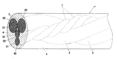
- FIG. 1 is an end perspective perspective view schematically showing a preferred embodiment of the composite cable of the present invention. It is the schematic which shows the outline of the apparatus used for the bending durability test in an Example.
- the composite cable of the present invention includes a sheath that surrounds at least the outer surface of a core composed of a plurality of large-diameter electric wires having a resin layer on the outer circumference of the conductor and a plurality of small-diameter electric wires having a resin layer on the outer circumference of the conductor. ing.
- the sheath is formed of a resin composition containing a base resin containing at least one of ethylene rubber and a styrene-based elastomer in an amount of 10 to 50% by mass.
- the core and the sheath are balanced, and flexibility when a composite cable is formed. It is considered that the wear resistance can be improved without impairing the bending resistance.
- the sheath made of the above resin composition can maintain excellent flexibility even in a low temperature range, and is therefore considered to exhibit excellent low temperature properties.
- the fact that the sheath surrounds the outer surface of the core means that the sheath is arranged (covered) on the outer surface of the core, that is, the sheath contains the core collectively.
- the sheath may collectively cover (built-in) the core with a separator (a layer formed of a resin such as paper, cloth, polyethylene terephthalate) interposed therebetween, and directly coat the core collectively. You may be doing it.
- the composite cable of the present invention is not particularly limited except for the material forming the sheath, and the same configuration as a known composite cable in which two or more sets of electric wires are integrated can be applied.
- a preferred embodiment of the composite cable of the present invention is a pair of large-diameter electric wires 2 having a resin layer 22 on the outer periphery of the conductor 21, and a conductor 31, as in the composite cable 1 shown in FIG. It has at least a core composed of a pair of small-diameter electric wires 3 having a resin layer 32 on the outer periphery, and has a sheath 4 surrounding the outer surface of the core.
- the core also referred to as a conductor core
- consisting of at least two large-diameter electric wires 2 and two small-diameter electric wires 3 consists of three stranded wires of the small-diameter electric wires 3 and two large-diameter electric wires 2. It is configured as a twisted wire.
- the composite cable of the present invention includes at least two types of electric wires having different diameters, specifically, a plurality of large-diameter electric wires and a plurality of small-diameter electric wires as a core.
- the large-diameter electric wire is the electric wire having the largest diameter among the electric wires constituting the conductor core
- the small-diameter electric wire is the electric wire having the smallest diameter among the electric wires constituting the conductor core.
- the large-diameter electric wire and the small-diameter electric wire are used for different purposes.
- the large-diameter electric wire and the small-diameter electric wire are usually used as a one-to-one set, but three or more electric wires may be used as one set.
- each set may be used for the same purpose or for different purposes.
- the arrangement state of the large-diameter electric wire and the small-diameter electric wire in the conductor core is not particularly limited, and an arrangement state applied to a normal core can be appropriately adopted. For example, they may be arranged independently of each other in parallel (parallel arrangement) or twisted and arranged (twisted wire).
- the large-diameter electric wire and the small-diameter electric wire may each form a stranded wire, but it is preferable that they form one stranded wire as a whole.
- the large-diameter electric wire and the small-diameter electric wire may be twisted wires, respectively, but as shown in FIG. It is preferable to use a uniform twisted wire.
- the number of electric wires, the arrangement of the electric wires, the twisting direction, the twisting pitch, etc. are not particularly limited and are appropriately set according to the application and the like.
- a resin such as polyethylene terephthalate (PET) or polypropylene (PP) can be interposed and twisted. As a result, the shape of the conductor core can be freely controlled.
- the large-diameter electric wire may have a resin layer on the outer periphery of the conductor, and a normal (insulated) electric wire can be used without particular limitation.
- the composite cable of the present invention may have at least two large-diameter electric wires, preferably 2 to 6, and more preferably 2 to 4. Further, the plurality of large-diameter electric wires may be built in as one set, or may be divided into a plurality of sets and built in.
- the outer diameter of the large-diameter electric wire is not particularly limited as long as it is thicker than the small-diameter electric wire described later, and can be appropriately determined according to the application and the like.
- the conductor cross section of the large-diameter electric wire is appropriately determined depending on the application and the like, but is preferably 0.3 to 8.0 SQ, and more preferably 0.5 to 3.0 SQ.
- the large-diameter electric wire is used for applications in which a larger current flows than the small-diameter electric wire described later.
- the conductor is not particularly limited, and examples thereof include a strand or a stranded wire obtained by twisting a plurality of strands, and a stranded wire is preferable.
- the cross-sectional shape of the conductor (wire) is not particularly limited, and may be a circular cross section (round line) or a rectangular cross section (flat line).
- the material for forming the conductor (wire) is not particularly limited, and examples thereof include copper, aluminum, and alloys thereof.
- the number of strands constituting the stranded wire is not particularly limited as long as it is a plurality (two or more). The arrangement, twisting direction, twisting pitch, etc. of the strands when twisting the strands are appropriately set according to the application and the like.
- the outer diameter of the conductor is not particularly limited, but is preferably larger than that of the conductor of the small-diameter electric wire described later, and can be appropriately determined according to the application and the like.
- the outer diameter is preferably 0.5 to 4.0 mm, more preferably 1.0 to 3.5 mm.
- the outer diameter of the strands constituting the stranded wire is not particularly limited as long as the outer diameter of the conductor is satisfied, but for example, 0.05 to 0.5 mm is preferable, and 0.05 to 0.3 mm is more preferable.
- the resin layer may be a single layer or a plurality of layers as long as it surrounds the outer peripheral surface of the conductor (covers the conductor).
- the resin layer is usually formed of a heat resistant resin.
- the heat-resistant resin is not particularly limited, and a resin that forms an ordinary (insulated) electric wire can be used without particular limitation. Examples thereof include thermoplastic resins and thermosetting resins, and more specifically, (cross-linked) polyethylene, polyamide, polyamideimide (PAI), polyimide (PI), polyurethane, chloroprene rubber, ethylene-vinyl acetate copolymer. Examples thereof include rubber made of (EVA rubber) and the like.
- the resin layer may contain various commonly used additives.
- the (total) layer thickness of the resin layer is not particularly limited and can be appropriately determined according to the application and the like. For example, in terms of heat resistance, flexibility, and abrasion resistance, 0.2 to 1.5 mm is preferable, and 0.2 to 1.0 mm is more preferable.
- the layer thickness of the resin layer is the shortest distance between the virtual circumscribed circle of all the strands constituting the conductor and the outer contour line of the resin layer in the cross section perpendicular to the axis of the electric wire. Means.
- the small-diameter electric wire may have a resin layer on the outer periphery of the conductor, and a normal (insulated) electric wire can be used without particular limitation.
- the composite cable of the present invention may have at least two small-diameter electric wires, preferably 2 to 12, and more preferably 2 to 6. Further, the plurality of small diameter electric wires may be built in as one set, or may be divided into a plurality of sets and built in.
- the small-diameter electric wire has an outer diameter smaller than that of the large-diameter electric wire, and has the same configuration, material, and the like as the large-diameter electric wire.
- the outer diameter of the small-diameter electric wire can be appropriately determined according to the application and the like.
- 0.5 to 2.5 mm is preferable, and 1.0 to 2.0 mm is preferable. More preferred.
- the difference in outer diameter from the large-diameter electric wire is not particularly limited, but is preferably 0.5 to 2.0 mm, for example.
- the conductor cross section of the small-diameter electric wire is appropriately determined depending on the application and the like, but for example, 0.05 to 2.0 SQ is preferable, and 0.05 to 1.25 SQ is more preferable.
- the outer diameter of the conductor in the small-diameter electric wire is appropriately determined according to the application and the like, and is preferably 0.3 to 2.0 mm, more preferably 0.3 to 1.5 mm, for example.
- the outer diameter of the strands constituting the stranded wire is not particularly limited as long as the outer diameter of the conductor is satisfied, but for example, 0.05 to 0.4 mm is preferable, and 0.05 to 0.05 to 0.3 mm is more preferable.
- the (total) layer thickness of the resin layer is not particularly limited and can be appropriately determined according to the application and the like. For example, in terms of heat resistance, flexibility, and abrasion resistance, 0.2 to 1.0 mm is preferable, and 0.2 to 0.5 mm is more preferable.
- a cross-linked polyethylene electric wire As the large-diameter electric wire and the small-diameter electric wire, it is preferable to use a cross-linked polyethylene electric wire.
- electric wires include cross-linked polyethylene insulated heat-resistant low-pressure electric wires for automobiles (AEX) and ultra-thin cross-linked polyethylene insulated heat-resistant low-pressure electric wires for automobiles (AESSX) as defined in Japan Automobile Technology Association (JASO) D 611. ), An electric wire using cross-linked polyethylene having a heat resistant temperature equivalent to 120 ° C. as a base resin can be mentioned.
- the cross-linked polyethylene electric wire may be appropriately manufactured or a commercially available one may be used.
- the conductor core may have (insulated) electric wires in addition to the above-mentioned large-diameter electric wires and small-diameter electric wires.
- the outer diameter of this electric wire may be smaller than that of the large-diameter electric wire and thicker than that of the small-diameter electric wire, and the structure and material thereof are the same as those of the large-diameter electric wire and the small-diameter electric wire.
- the composite cable of the present invention has a sheath that covers the outer surface of the conductor core.
- the sheath can be a sheath of a normal composite cable except that it is formed of a resin composition described later.
- the sheath may be a single layer or a plurality of layers, and the layer thickness thereof can be appropriately determined according to the application and the like.
- the layer thickness of the sheath is preferably, for example, 0.5 to 3.0 mm, more preferably 0.8 to 2.0 mm in terms of flexibility, bending resistance and abrasion resistance.
- the layer thickness of the sheath means the shortest distance between the virtual circumscribed circle of all conductors constituting the conductor core and the outer contour line of the sheath in the cross section perpendicular to the axis of the composite cable.
- the cross-sectional shape (outer contour line) of the composite cable is not particularly limited, but is usually circular.
- the outer diameter of the sheath (synonymous with the diameter of the composite cable and corresponding to the diameter of the outer contour line) can be appropriately determined according to the application and is not particularly limited. For example, 5.0 to 30.0 mm is preferable, and 5.0 to 15.0 mm is more preferable, in terms of flexibility, bending resistance, and abrasion resistance.
- the sheath is made of a resin composition containing a base resin containing at least one of ethylene rubber and a styrene-based elastomer in an amount of 10 to 50% by mass.
- a resin composition containing a base resin containing at least one of ethylene rubber and a styrene-based elastomer in an amount of 10 to 50% by mass.
- the fact that the sheath (resin layer) is made of a resin composition means that the sheath (resin layer) is made of a resin composition, and is formed of a non-crosslinked product of the resin composition. It includes both aspects of the resin composition formed of a crosslinked product. In terms of abrasion resistance and heat resistance, an embodiment formed of a crosslinked resin composition is preferable.
- the crosslinked product of the resin composition forming the sheath is an electron beam crosslinked product or a silane crosslinked product of the (crosslinkable) resin composition (silane crosslinkability described later) in terms of abrasion resistance, heat resistance, and assembly workability.
- the silanol condensed and cured product of the resin composition) is preferable, and the silane crosslinked product is more preferable. Details of the resin composition and the cured product thereof will be described in the method for manufacturing a composite cable described later.
- the composite cable of the present invention is suitably used as an electronic control cable for various products such as industrial machines, industrial robots, and vehicles. Among them, since it is excellent in flexibility and bending resistance, it is more preferably used as an electronic control cable for a product having two or more relatively movable members. In particular, it is suitably used for brake control of automobiles (ABS and EPB), moving parts of industrial robots, and the like. When used in an automobile brake system, it is preferable that two large-diameter electric wires of a composite cable are used as a pair of power lines for EPB and two small-diameter electric wires are used as a pair of signal lines for ABS.
- the large-diameter electric wire (power line) is electrically connected to the control device of the electric parking brake mounted on the vehicle body and the actuator arranged on the tire side, and the control device supplies electric power to the actuator.
- the small diameter electric wire (signal line) is electrically connected to the ABS control device mounted on the vehicle body and the ABS sensor arranged on the tire side, and the ABS sensor is transferred to the ABS control device (tire locked state). (Transmit) Send a signal.
- the cable for transmitting the signal for controlling the brake caliper based on this signal may be the same as or different from the small diameter electric wire (signal line), and is appropriately determined.
- the composite cable is usually connected to a predetermined control device and sensor by processing the end (terminal) of the small-diameter electric wire and the large-diameter electric wire.
- the composite cable of the present invention is excellent not only in bending resistance but also in flexibility, the terminal-processed composite cable can be easily bent (with a weak force) for wiring work (assembly work).
- the material or component used for manufacturing the composite cable of the present invention will be described.
- ⁇ Electric wire> In manufacturing the composite cable of the present invention, two or more types of electric wires having different diameters, for example, the cross-linked polyethylene electric wire as the large diameter electric wire and the small diameter electric wire are prepared. This electric wire may be appropriately manufactured according to a usual method, or a commercially available product may be used.
- the resin composition used to form the sheath contains a base resin containing at least one of ethylene rubber and a styrene-based elastomer in an amount of 10 to 50% by mass.
- This resin composition may be non-crosslinked when the sheath is formed, but it is preferably crosslinked by irradiation with an electron beam (electron beam crosslink) or crosslinked by a silane crosslinking method described later (silane crosslinking). ..
- Base resin Ethylene rubber and styrene-based elastomers have a grafting reaction with a silane coupling agent grafting reaction site at a site that can be crosslinked by electron beam cross-linking or at a silane cross-linking (in the presence of radicals generated from an organic peroxide described later). It has a possible site, in or at the end of the main chain. Examples of the crosslinkable site or the grafting reactionable site include an unsaturated bond site of a carbon chain and a carbon atom having a hydrogen atom.
- the base resin may contain other resins, and may further contain organic mineral oils and the like.
- the ethylene rubber is not particularly limited as long as it is a rubber (including an elastomer) made of a copolymer obtained by copolymerizing a compound having an ethylenically unsaturated bond, and known ones can be used.
- Preferred examples of ethylene rubber include a binary copolymer rubber of ethylene and ⁇ -olefin, and a ternary copolymer rubber of ethylene, ⁇ -olefin and diene.
- the diene component of the ternary copolymer may be a conjugated diene component or a non-conjugated diene component, but a non-conjugated diene component is preferable.
- each ⁇ -olefin component having 3 to 12 carbon atoms is preferable.
- the conjugated diene component include butadiene, isoprene, 1,3-pentadiene, 2,3-dimethyl-1,3-butadiene and the like, and butadiene component and the like are preferable.
- Specific examples of the non-conjugated diene component include, for example, dicyclopentadiene (DCPD), ethylidene norbornene (ENB), 1,4-hexadiene and the like.
- EPM Ethylene-propylene rubber
- EPDM ethylene-propylene-diene rubber
- ethylene rubber one type may be used alone or two or more types may be used.
- the styrene-based elastomer refers to a polymer composed of an aromatic vinyl compound in the molecule.
- examples of such styrene-based elastomers include block copolymers and random copolymers of conjugated diene compounds and aromatic vinyl compounds, and hydrogenated products thereof.
- examples of such styrene-based elastomers include styrene-ethylene-butylene-styrene block copolymer (SEBS), styrene-isoprene-styrene block copolymer (SIS), hydride SIS, and styrene-butadiene-styrene block.
- SBS Polymer
- SEEPS styrene-ethylene-ethylene-propylene-styrene block copolymer
- SEPS styrene-ethylene-propylene-styrene block copolymer
- SBR styrene-butadiene rubber
- HSBR styrene-hydride rubber hydride
- the styrene-based elastomer one type may be used alone or two or more types may be used.
- the other resin that may be contained in the base resin is not particularly limited, but a polyolefin resin is preferable because it can be crosslinked with an electron beam or a silane coupling agent described later can undergo a grafting reaction.
- the polyolefin-based resin is not particularly limited as long as it is a resin composed of a homopolymer or a copolymer of a compound having an ethylenically unsaturated bond, and those used for ordinary electric wires or cables can be used.
- Examples thereof include resins such as polyethylene, polypropylene, ethylene- ⁇ -olefin copolymers, polyolefin copolymers having an acid copolymer component or an acid ester copolymer component, and rubbers or elastomers of these polymers.
- the rubber or elastomer may be any other than ethylene rubber and styrene-based elastomer, and examples thereof include copolymer rubber of alkyl acrylate and ethylene (ethylene acrylic rubber).
- each resin such as polyethylene, polypropylene, ethylene- ⁇ -olefin copolymer, and polyolefin copolymer having an acid copolymer component is preferable.
- Polyethylene resin is more preferable because it has a large effect of improving wear resistance when used in combination with ethylene rubber or a styrene-based elastomer.
- the polyethylene resin may be a polymer resin containing an ethylene component, for example, high density polyethylene (HDPE), low density polyethylene (LDPE), ultrahigh molecular weight polyethylene (UHMW-PE), linear low density polyethylene. (LLDPE), ultra-low density polyethylene (VLDPE). Of these, linear low-density polyethylene and low-density polyethylene are preferable.
- Examples of the resin of the polyolefin copolymer having an acid copolymer component or an acid ester copolymer component include an ethylene-vinyl acetate copolymer, an ethylene- (meth) acrylic acid copolymer, and an ethylene- (meth) acrylic acid alkyl. Examples thereof include each resin made of a copolymer (preferably 1 to 12 carbon atoms) copolymer or the like.
- One type of polyolefin resin may be used alone, or two or more types may be used in combination.
- organic mineral oil those usually used in the resin composition can be used without particular limitation, and paraffin-based oils and naphthenic oils are mentioned, and paraffin-based oils are preferable.
- One type of organic mineral oil may be used alone, or two or more types may be used in combination.
- the total content of the ethylene rubber and the styrene-based elastomer in the base resin is 10 to 50% by mass, preferably 20% by mass or more, and more preferably 30% by mass or more.
- the upper limit of the total content is preferably 45% by mass or less.
- the content of ethylene rubber or styrene-based elastomer in the base resin is appropriately set within a range that satisfies the above total content.
- the content of ethylene rubber or styrene-based elastomer is preferably 10 to 40% by mass, more preferably 20 to 40% by mass, respectively.
- the total content of the polyolefin-based resin in the base resin is not particularly limited, but is preferably 0 to 50% by mass, more preferably 10 to 40% by mass.
- the content of each of the above resins included in the polyolefin-based resin in the base resin is appropriately set within a range that satisfies the above-mentioned content of the polyolefin-based resin.
- the content of the polyethylene resin is preferably 0 to 40% by mass, more preferably 20 to 30% by mass.
- the content of the organic mineral oil in the base resin is not particularly limited, but is preferably 0 to 40% by mass, more preferably 10 to 35% by mass.
- the ratio ( CE : CO ) of the (total) content ( CE ) of ethylene rubber and styrene-based elastomer to the content ( CO ) of organic mineral oil is 50:50 to 75:25. Is preferable, and 55:45 to 65:35 is more preferable.
- the resin composition preferably contains the following inorganic filler in addition to the above base resin, and may contain various additives such as antioxidants.
- the content of the inorganic filler in the base resin is as described later.
- the resin composition When the resin composition is silane crosslinkable, it preferably contains a silane coupling agent graft-bonded to the base resin and a silanol condensation catalyst in addition to the base resin, and may further contain an inorganic filler. preferable. Thereby, the heat resistance and the wear resistance can be improved to a higher level. As each of these components, one type may be used, or two or more types may be used.
- silane coupling agent grafted and bonded to the base resin has undergone a grafting reaction with the base resin in the resin composition.
- a silane coupling agent is preferably obtained by grafting reaction with a base resin in the presence of an organic peroxide.
- a grafting reaction site (group) capable of performing a grafting reaction with a site capable of grafting the base resin in the presence of radicals generated by decomposition of an organic peroxide described later.
- it is not particularly limited as long as it has a hydrolyzable silyl group capable of condensing silanol).
- silane coupling agent examples include silane coupling agents used in ordinary silane cross-linking methods.
- silane coupling agent examples include a silane coupling agent having a vinyl group or a (meth) acryloyl group as a grafting reaction site. Specifically, vinyltrimethoxysilane, vinyltriethoxysilane, vinyltributoxysilane, vinyldimethoxyethoxysilane, vinyldimethoxybutoxysilane, vinyldiethoxybutoxysilane, allyltrimethoxysilane, allyltriethoxysilane, vinyltriacetoxysilane.
- Examples thereof include (meth) acryloxisilanes such as vinylsilane, methacrypropyltrimethoxysilane, methacrypropyltriethoxysilane, and methaloxypropylmethyldimethoxysilane. Of these, vinyltrimethoxysilane or vinyltriethoxysilane is particularly preferable.
- the organic peroxide used in the grafting reaction generates radicals by at least thermal decomposition, and as a catalyst, the grafting reaction by the radical reaction of the silane coupling agent to the base resin (the grafting reaction site of the silane coupling agent). It is a covalent bond forming reaction with a site capable of grafting reaction of the base resin, and also has a function of causing a (radical) addition reaction).
- an organic peroxide those having the above-mentioned functions and used in radical polymerization or a usual silane cross-linking method can be used without particular limitation.
- the decomposition temperature of the organic peroxide is preferably 80 to 195 ° C, particularly preferably 125 to 180 ° C.
- the decomposition temperature refers to the temperature at which heat absorption or heat generation starts when heated from room temperature at a heating rate of 5 ° C./min in a nitrogen gas atmosphere by thermal analysis such as the DSC method.
- silane crosslinkable resin composition as the base resin and the silane coupling agent grafted and bonded to the base resin, a base resin appropriately synthesized or commercially available, and a base resin grafted and bonded to the base resin and the silane coupling agent. (Silane graft resin) can be used.
- the silanol condensation catalyst causes a silanol condensation reaction (promotion) of a silane coupling agent grafted on a base resin in the presence of water.
- silanol condensation catalyst is not particularly limited, and examples thereof include an organotin compound, a metallic soap, and a platinum compound.
- organotin compound include organotin compounds such as dibutyltin dilaurate, dioctyltin dilaurate, dibutyltin dioctate, and dibutyltin diacetate.
- the silanol condensation catalyst is preferably used as a mixture (catalyst masterbatch) with a resin (carrier resin).
- the resin is not particularly limited, but each resin described in the above base resin can be used.
- the inorganic filler preferably has a site on the surface where a hydrogen bond or the like can be formed with the hydrolyzable silyl group of the silane coupling agent or a site where a chemical bond can be formed by a covalent bond.
- the site capable of chemically bonding with the hydrolyzable silyl group of the silane coupling agent include an OH group (hydroxyl group, water molecule of water-containing or water of crystallization, OH group such as carboxy group), amino group, SH group and the like.
- inorganic filler examples include aluminum hydroxide, magnesium hydroxide, calcium carbonate, magnesium carbonate, calcium silicate, magnesium silicate, calcium oxide, magnesium oxide, aluminum oxide, aluminum nitride, aluminum borate whisker, and hydrated aluminum silicate.
- at least one selected from the group consisting of silica, aluminum hydroxide, magnesium hydroxide, calcium carbonate and antimony trioxide is preferable.
- the inorganic filler is preferably particles, and its average particle size is appropriately set. As the inorganic filler, one that has been surface-treated with a normal surface treatment agent can also be used.
- the content of the base resin in the resin composition is not particularly limited, but is preferably 30 to 80% by mass, more preferably 40 to 70% by mass, for example.
- the content of each component is set with respect to 100 parts by mass of the base resin.
- the 100 parts by mass of the base resin means the total content of each component constituting the base resin, and usually means the total amount of the resin component including ethylene rubber, styrene elastomer and polyolefin resin and the organic mineral oil. To do.
- the silane crosslinkable resin composition the content of each component constituting the base resin in the base resin is as described above.
- the content of the silane coupling agent in the silane crosslinkable resin composition is preferably 1 to 15 parts by mass, more preferably 3 to 12 parts by mass, and 4 to 12 parts by mass with respect to 100 parts by mass of the base resin. More preferred.
- the silane coupling agent is grafted to the polyolefin resin, the content of the silane coupling agent is the content converted into the content of the silane coupling agent before the grafting reaction.
- the content of the silanol condensation catalyst in the silane crosslinkable resin composition is not particularly limited, but is preferably 0.001 to 0.6 parts by mass, more preferably 0.01 to 0.01 parts by mass with respect to 100 parts by mass of the base resin. It is 0.4 parts by mass.
- the silane crosslinkable resin composition contains an inorganic filler
- the content of the inorganic filler is preferably 10 to 150 parts by mass, more preferably 30 to 120 parts by mass, and 50 to 100 parts by mass with respect to 100 parts by mass of the base resin. Parts by mass are more preferred.
- the blending amount of other resins and the above additives that can be used in addition to the above components is appropriately set as long as the object of the present invention is not impaired.
- the method for manufacturing the composite cable of the present invention will be described.
- ⁇ Manufacturing of conductor core> When the conductor core has a stranded wire structure, the prepared electric wire is used and twisted by a usual method to form a stranded wire.
- the production method in the examples can be mentioned.
- the sheath can be formed by arranging a resin composition on the outer surface of the conductor core and optionally cross-linking the sheath.
- the method of forming the sheath differs depending on the presence or absence of cross-linking and the cross-linking method.
- each component is mixed to prepare a resin composition.
- the mixing method is not particularly limited as long as it is a method usually used for preparing a composition, and various mixing devices can be used.
- the mixing conditions are not particularly limited and are appropriately set, but usually, the mixture is mixed under the melting of the base resin.
- the obtained resin composition is placed (molded) on the outer surface of the conductor core.
- the method of arranging is not particularly limited, and examples thereof include an extrusion molding method, an injection molding method, and a molding method using another molding machine, and a method of extrusion molding at the same time as the conductor core is preferable.
- the molding temperature is set to a temperature at which the base resin melts according to various conditions of the type of the base resin and the extrusion speed (take-up speed), and can be set to, for example, 80 to 250 ° C.
- the preparation and molding of the resin composition can be carried out simultaneously or continuously.
- the composite cable of the present invention can be manufactured by arranging the layer of the resin composition on the outer surface of the conductor core and having a sheath made of a non-crosslinked product of the resin composition.
- a polyfunctional vinyl compound such as divinylbenzene or triallyl cyanurate, ethylene glycol dimethacrylate, diethylene glycol dimethacrylate, or tri.
- examples thereof include polyfunctional (meth) acrylate compounds such as ethylene glycol dimethacrylate, polyethylene glycol dimethacrylate, trimethyl propantrimethacrylate, and allyl methacrylate.
- the cross-linking aid used in the examples can be mentioned.
- the content of the cross-linking agent is preferably 1 to 5 parts by mass with respect to 100 parts by mass of the base resin.
- the electron beam irradiation conditions are appropriately set according to the type of base resin, the degree of cross-linking, and the like. In this way, the composite cable of the present invention having a sheath made of an electron beam crosslinked product of a resin composition can be manufactured.
- Silane crosslinkable resin composition It contains a base resin containing at least one of ethylene rubber and a styrene-based elastomer in an amount of 10 to 50% by mass, a silane coupling agent graft-bonded to the base resin, and a silanol condensation catalyst, preferably containing an inorganic filler.
- the silane crosslinkable resin composition can be prepared in the same manner as the above non-crosslinkable resin composition using a commercially available silane graft resin, but is preferably prepared by the following step (1).
- Step (1) The base resin, the silane coupling agent, the silanol condensation catalyst, and preferably the inorganic filler are melt-mixed in the presence of the organic peroxide at a temperature equal to or higher than the decomposition temperature of the organic peroxide.
- Step (2) Step of arranging the silane crosslinkable resin composition on the outer peripheral surface of the conductor core
- Step (3) Step of bringing the silane crosslinkable resin composition into contact with water to crosslink.
- the mixing order of each component is not particularly limited, and may be mixed in any order.
- the conditions in the step (1-1b) described later can be applied.
- the base resin and the silane coupling agent are grafted with radicals generated from the organic peroxide.
- a silane graft resin is synthesized, and a silane crosslinkable resin composition containing the silane graft resin is prepared as a reaction composition.
- the silane graft resin to be synthesized is also called a silane crosslinkable resin.
- This silane crosslinkable resin composition contains a silane graft resin in which a silane coupling agent is grafted onto the base resin to the extent that it can be molded by the step (2) described later.
- each component can be melt-mixed at once (also referred to as melt-kneading or kneading), but each of the above-mentioned components is melted by the following steps (1-1) and (1-2). It is preferable to mix.
- Step (1-1) A step of melt-mixing the base resin, the silane coupling agent, and preferably an inorganic filler at a temperature equal to or higher than the decomposition temperature of the organic peroxide in the presence of the organic peroxide.
- silane MB silane masterbatch
- the silane MB contains a silane graft resin in which a silane coupling agent is grafted onto the base resin to the extent that it can be molded by the step (2) described later.
- the mixing order of each component is not particularly limited, and any order may be used, and each of the above components may be melt-mixed at once. In this case, it is preferable to dry-blend the above components in advance and then melt-mix them.
- the methods and conditions for dry blending and melt mixing the methods and conditions described in the following steps (1-1a) and (1-1b) can be adopted.
- the step (1-2) of melt-mixing the silane MB and the silanol condensation catalyst is then performed.
- a mixture with a carrier resin as a silanol condensation catalyst can be used.
- the catalyst masterbatch (catalyst MB) can be prepared, for example, by melting and mixing the balance of the base resin and the silanol condensation catalyst.
- the melt-mixing at this time may be performed under melting of the carrier resin, and can be performed in the same manner as the melt-mixing in the above step (1-1b), for example.
- the mixing temperature can be set, for example, 80 to 250 ° C, more preferably 100 to 240 ° C.
- the mixing of the silane MB with the silanol condensation catalyst or the catalyst MB may be carried out under the melting of the base resin, and can be carried out in the same manner as the melting and mixing of the step (1-1b), for example.
- the mixing temperature can be set, for example, 80 to 250 ° C, more preferably 100 to 240 ° C.
- the blending amount of the silanol condensation catalyst is as described above.
- a resin other than the base resin, an inorganic filler, or the like can be mixed.
- silane crosslinkable resin composition can be obtained as a melt mixture of the silane MB and the silanol condensation catalyst or the catalyst MB.
- This silane crosslinkable resin composition is an uncrosslinked product in which the hydrolyzable silyl group derived from the silane coupling agent is not silanol-condensed.
- partial cross-linking is unavoidable by melt-mixing in step (1-2), but it is preferable that the moldability in step (2) described later is maintained.
- the base resin can be melt-mixed in the above step (1-1) or step (1-1b), a part thereof is melt-mixed and the rest is used as a carrier resin in the above step (1-2). It is preferable to melt and mix.
- 100 parts by mass of the base resin means the total amount of the base resin blended in the step (1-1) or the step (1-1b) and the base resin blended in the step (1-2). ..
- a part of the base resin to be blended is preferably 50 to 98% by mass with respect to the total amount, and the balance is preferably 2 to 50% by mass.
- the method of premixing the inorganic filler and the silane coupling agent is not particularly limited, and may be wet mixing or dry mixing.
- dry mixing dry blending in which a silane coupling agent is added to an inorganic filler with or without heating and mixed is preferable.
- the mixing temperature can be set at preferably 10 to 60 ° C., more preferably around room temperature (25 ° C.) (for example, 20 to 35 ° C.), and set to a condition of about several minutes to several hours.
- the inorganic filler to which the silane coupling agent is bonded or adsorbed with a strong bond via a hydrolyzable silyl group capable of silanol condensation
- the silane cup with a weak bond on the surface can be prepared.
- Weak bonds include hydrogen bond interactions, ion, partial charge or dipole interactions, and adsorption actions, and strong bonds are chemical bonds with potential chemical bonds on the surface of the inorganic filler. And so on. This bond can reduce the volatilization of the silane coupling agent during melt mixing in the subsequent steps (1-1b) and step (1-2).
- the organic peroxide may be present or the base resin may be present as long as the mixture is mixed at a temperature lower than the decomposition temperature of the organic peroxide.
- step (1-1a) The mixture obtained in step (1-1a), the base resin (all or part), and the residual components not mixed in step (1-1a) were then added in the presence of an organic peroxide. , Melting and mixing at a temperature equal to or higher than the decomposition temperature of the organic peroxide (step (1-1b)).
- the organic peroxide may be present when the step (1-1b) is performed, and may be mixed in the step (1-1a) or may be mixed in the step (1-1b).
- the blending amount of the organic peroxide is not particularly limited, but is preferably 0.01 to 0.6 parts by mass, and more preferably 0.05 to 0.3 parts by mass with respect to 100 parts by mass of the base resin.
- the temperature at which the above components are melt-mixed is equal to or higher than the decomposition temperature of the organic peroxide, preferably the decomposition temperature of the organic peroxide + (25 to 110) ° C., for example, 150 to The temperature is 230 ° C.
- Other melt-mixing conditions, such as mixing time, can be set as appropriate.
- the organic peroxide is decomposed and acts on the silane coupling agent to proceed with the grafting reaction of the silane coupling agent to the base resin.
- the mixing method is not particularly limited as long as it is a method usually used for rubber, plastic and the like.
- the mixing device is appropriately selected depending on, for example, the blending amount of the inorganic filler.
- a single-screw extruder, a twin-screw extruder, a roll, a Banbury mixer, various kneaders, or the like is used as the mixing device.
- a closed mixer such as a Banbury mixer or various kneaders is preferable in terms of the dispersibility of the resin component and the stability of the crosslinking reaction.
- step (1-1b) is performed to cause the base resin and the silane coupling agent to undergo a grafting reaction.
- a silane MB containing a silane graft resin is prepared.
- the silane coupling agent binds or adsorbs to or adsorbs a chemically bonded site of the inorganic filler with its hydrolyzable silyl group. Further, in the melt mixing of the above step (1-1b), this silane coupling agent undergoes a grafting reaction with a site capable of a grafting reaction of the base resin at the grafting reaction site.
- Examples of the grafting reaction include a mode in which the silane coupling agent bonded or adsorbed to the inorganic filler with a weak bond is desorbed from the inorganic filler and grafted to the base resin, and a silane cup bonded or adsorbed with the inorganic filler with a strong bond.
- Examples thereof include an embodiment in which the ring agent undergoes a grafting reaction with the base resin while maintaining the bond with the inorganic filler.
- silane crosslinkable resin composition is prepared by performing the above step (1-2).
- the silanol condensation catalyst for example, 0.01 mass with respect to 100 parts by mass of the resin composition. It is preferable to melt and mix at a ratio of less than one part) to suppress the condensation reaction of the silane coupling agent.
- the step (2) of arranging the silane cross-linking resin composition on the outer peripheral surface of the conductor core is then performed.
- the step (2) may be any method as long as the conductor core can be coated with the silane crosslinkable resin composition, and an appropriate molding method is applied.
- examples of the molding method include extrusion molding using an extruder, injection molding using an injection molding machine, and molding using another molding machine.
- extrusion molding in which the conductor core and the silane crosslinkable resin composition are coextruded is preferable. Extrusion molding can be performed using a general-purpose extrusion molding machine.
- the extrusion molding temperature is appropriately set according to the type of the base resin or the carrier resin and various conditions of the extrusion speed (take-up speed), and is preferably set to, for example, 80 to 250 ° C.
- a powdery lubricant such as talc, a liquid lubricant such as silicone, or a tape or the like is applied to the outer peripheral surface of the conductor core to hold the conductor core between the conductor core and the sheath. Adhesion force can be appropriately controlled.
- the cross-sectional shape and thickness of the sheath can be adjusted using a base with an appropriate structure. It is preferable that the step (2) is carried out at the same time as or continuously of the step (1-2).
- each MB can be mixed under unmelted base resin or carrier resin, for example, dry blended.
- the method and conditions for dry blending are not particularly limited, and examples thereof include dry mixing in step (1-1a) and the conditions thereof.
- the silane MB and the silanol condensation catalyst are not kept in a high temperature state for a long time in a mixed state.
- the step (3) of bringing the silane cross-linking resin composition into contact with water for cross-linking is then performed.
- the hydrolyzable silyl group of the silane coupling agent is hydrolyzed to silanol (OH group bonded to the silicon atom), and the hydroxyl groups of silanol are bonded to each other by the silanol condensation catalyst present in the silane crosslinkable resin composition. Condense.
- Step (3) can be performed by a usual method.
- the condensation reaction proceeds at room temperature in the presence of a silanol condensation catalyst. Therefore, it is not necessary to positively contact the silane crosslinkable resin composition arranged on the outer peripheral surface of the conductor core with water.
- the silane cross-linking resin composition can also be brought into contact with water. For example, a method of actively contacting with water such as exposure to a high humidity atmosphere, flooding with hot water, charging into a moist heat tank, and exposure to high-temperature steam can be adopted. Further, at that time, pressure may be applied to allow water to permeate inside.
- the silane coupling agent strongly bonded to the inorganic filler does not easily undergo a silanol condensation reaction, maintains the bond with the inorganic filler, and enables strong adhesion (high affinity) between the base resin and the inorganic filler.
- the silane coupling agent weakly bonded to the inorganic filler undergoes a silanol condensation reaction to crosslink the base resins via silanol bonds (siloxane bonds).
- steps (1) to (3) are carried out, and a sheath made of a silane crosslinked product of the silane crosslinkable resin composition is formed on the outer peripheral surface of the conductor core.
- the silane crosslinked product is a hydrolyzable silyl of a silane coupling agent bonded to a silane graft resin with respect to a silane graft resin in which a specific amount of the silane coupling agent is grafted onto a base resin containing an ethylene rubber or a styrene elastomer.
- the group is crosslinked by silanol condensation.
- This silane graft resin contains a crosslinked resin in which base resins are bonded to each other via a silane coupling agent (siloxane bond).
- the silanol condensate-cured product of the silane crosslinkable resin composition containing the inorganic filler is at least two types of crosslinked resins according to the binding force between the inorganic filler and the silane coupling agent in the above step (1-1a), that is,
- the base resin contains a crosslinked resin bonded (crosslinked) to the inorganic filler via a silane coupling agent.
- the silane crosslinked product has, as a constituent component, a constituent component derived from at least one of ethylene rubber and a styrene-based elastomer, a constituent component derived from a silane coupling agent, and preferably a constituent component derived from an inorganic filler.
- JP-A-2017-145370 can be appropriately applied to each step in the above production method, the reaction in the silane cross-linking method, and the form of the obtained condensed cured product, and the content described in this publication remains unchanged. Incorporated as part of the description herein.
- Baymac DP Product name, Acrylic rubber, DuPont Skyprene E-33: Product name, Chloroprene rubber, Tosoh ⁇ Inorganic filler>
- Magnesium hydroxide Magnes LN-6 (trade name), manufactured by Konoshima Chemical Co., Ltd.
- Perhexa 25B Trade name, 2,5-dimethyl-2,5-di (tert-butylperoxy) hexane, decomposition temperature 154 ° C, manufactured by NOF CORPORATION ⁇ Silanol condensation catalyst> ADEKA STAB OT-1: Product name, Dioctyl tin dilaurate, manufactured by ADEKA ⁇ Crosslinking aid> Ogmont T200: Product name, trimethylolpropane trimethacrylate, NK ester 3G manufactured by Shin-Nakamura Chemical Industry Co., Ltd .: Product name, methacrylate-based cross-linking aid, manufactured by Shin-Nakamura Chemical Industry Co., Ltd.
- Example 1 A sheath was formed by electron beam cross-linking as follows to manufacture a 4-core composite cable shown in FIG. As shown in the column 1 of Example 1 in Table 1, each component is put into a Banbury mixer, melt-mixed at 120 to 200 ° C. for 10 minutes, discharged at a material discharge temperature of 200 ° C., and passed through a feeder ruder to form a resin composition. Pellets were obtained. Using the prepared conductor core and the obtained pellets, a sheath was formed as follows.
- the pellets were directly extruded (arranged) on the outer peripheral surface of the conductor core with a wall thickness of 1 mm to obtain a cable having an outer diameter of 8 mm.
- the resin composition arranged on the outer peripheral surface of the conductor core was irradiated with an electron beam under an accelerating voltage of 500 kV. In this way, the composite cable (outer diameter 8 mm) of Example 1 provided with a sheath having a layer thickness of 1 mm formed of an electron beam crosslinked product was manufactured.
- Examples 2 and 3 The composite cables of Examples 2 and 3 were produced in the same manner as in Example 1 except that the resin composition was prepared with the composition shown in each Example column of Table 1.
- Example 4 A sheath was formed by a silane cross-linking method as follows to manufacture a 4-core composite cable shown in FIG. (Preparation of silane MB) The silane coupling agent and the organic peroxide are mixed at 25 ° C. (dry blend) at the blending amount shown in Example 4 of Table 1, then the inorganic filler is added thereto and mixed at 30 ° C. (dry blend). (Step (1-1a)).
- the obtained mixture and the base resin in the blending amount shown in column 4 of Example 4 of Table 1 are put into a Banbury mixer and melt-mixed at 120 to 200 ° C. for 10 minutes. After that, the material was discharged at a material discharge temperature of 200 ° C., and pellets of silane MB were obtained through a feeder ruder (step (1-1b)).
- a silane graft resin was synthesized by inducing a silane grafting reaction by melt mixing with the above Banbury mixer.
- Example 4 Example 4 of Table 1.
- Example 4 the composite cable (outer diameter 8 mm) of Example 4 provided with a sheath having a layer thickness of 1 mm formed of a silane crosslinked product was manufactured.
- Examples 5 to 10, 12 to 18 and Comparative Examples 2 to 5 Composite cables were produced in the same manner as in Example 4 except that the silane MB and the catalyst MB were prepared with the compositions shown in each Example column or Comparative Example column of Table 1 or Table 2. However, in Example 13 and Comparative Examples 2 to 4, the step (1-1b) was performed instead of the step (1-1a).
- Example 11 In Example 11 having a sheath having a layer thickness of 1 mm formed of a non-crosslinked resin composition in the same manner as in Example 1 except that the resin composition arranged on the outer peripheral surface of the conductor core is not irradiated with an electron beam. A composite cable (outer diameter 8 mm) was manufactured.
- Each of the manufactured examples and comparative composite cables is a 4-core composite cable in which the large-diameter electric wire is an EPB cable (power supply line) and the small-diameter electric wire is an ABS cable (signal line).
- a 2-core ABS cable was manufactured. Two cross-linked polyethylene electric wires (small diameter electric wires) having a conductor cross-sectional area of 0.25 SQ were twisted together to prepare a conductor core made of twisted wires (twisting ratio 2%) of the small diameter electric wires. Next, a reference having a sheath having a layer thickness of 1 mm as an electron beam crosslinked product in the same manner as in Example 1 except that a resin composition having the composition shown in the reference example column of Table 2 was prepared using this conductor core. The example cable (outer diameter 5 mm) was manufactured.
- the value of the minor axis of the test piece deformed into an elliptical shape with the weight attached was measured to evaluate the flexibility.
- the evaluation is performed based on which of the following criteria the minor axis value is included, and rank D or higher is a pass of this test.
- FIG. 2 is a schematic view of the apparatus used in this test as viewed from the axial direction of the mandrel.
- the cable 102 is passed vertically between the two mandrel 51 and 52 arranged horizontally and parallel to each other, and between the pressers 61 and 62 for preventing shaking, and the weight is placed below the cable 102. 7 was attached.
- the upper end of the cable 102 was bent so as to alternately contact the upper outer circumference of the left and right mandrel 51 or 52 (repeatedly repeating left and right).
- the number of times of bending was counted with the case where the cable 102 was bent so as to be in contact with the outer periphery of either the left or right mandrel 51 or 52 as one time.
- the test conditions were a mandrel diameter of 10 mm, a left-right bending angle of 90 °, a speed of 60 bends / minute, a weight of 500 g, a clearance between the cable and the mandrel of 1 mm, and the upper side surface of the cable 102 was the upper outer circumference of each mandrel.
- the bending length was adjusted so as to be in contact with the water, and the test was conducted in an atmosphere of 25 ° C.
- the cables were connected in series in a loop to energize, and the number of bends until disconnection occurred was measured.
- the evaluation is performed based on which of the following criteria includes the number of bends until disconnection occurs, and rank C or higher is a pass of this test.
- D Less than 50,000 times
- Heat resistance test The heat resistance and terminal workability of the cables manufactured in Examples and Comparative Examples were evaluated by the following reference tests. Heat resistance and terminal workability are suitable characteristics required for the cable depending on the application.
- Heat resistance test The cable was wound around a mandrel having the same outer diameter as the cable, placed in a constant temperature bath at 250 ° C. for 30 minutes, and the presence or absence of cracks in the sheath was confirmed. The test results are marked with " ⁇ " when the sheath is not cracked (cannot be confirmed) (passed this reference test), and "x" when cracked (failed this reference test). expressed.
- Terminal workability test The peelability at the end of the cable at 100 mm when the sheath was peeled off was evaluated. Specifically, a notch that goes around in the circumferential direction perpendicular to the axial direction of the composite cable is made at a depth of 90% of the coating thickness of the composite cable. Next, the sheath of one composite cable was grasped with this notch as a boundary, and the other composite cable was pulled out. For the composite cable pulled out in this way, the end workability test of the sheath was evaluated according to the following criteria. The pass of this reference test is " ⁇ ".
- a sheath formed of a resin composition containing a base resin containing at least one of ethylene rubber and a styrene-based elastomer in an amount of 10 to 50% by mass is provided on the outer surface of the conductor core.
- the composite cable has a high level of abrasion resistance, low temperature resistance, flexibility and bending resistance. That is, when a resin other than ethylene rubber and styrene-based elastomer or a base resin containing rubber (polyurethane, acrylic rubber or chloroprene rubber) is used, any of the above four characteristics is inferior and does not exhibit sufficient characteristics.
- the ABS cable of the reference example has an outer diameter of 5 mm and a small diameter, it has passed the flexibility test and the bending resistance test, but the composite cable of Comparative Example 1 in which the sheath is formed of the same material (outside). (Diameter 8 mm) failed both the flexibility and bending resistance tests, and the characteristics deteriorated significantly.
- a base resin containing ethylene rubber and a styrene-based elastomer in a specific amount is used, the above four characteristics can be improved to an excellent level even if the outer diameter is increased to 8 mm by compounding.
- a sheath is formed of a crosslinked product of a resin composition, particularly a crosslinked product of silane, a composite cable having the above four characteristics at a higher level and exhibiting high heat resistance can be obtained.
Landscapes
- Physics & Mathematics (AREA)
- Spectroscopy & Molecular Physics (AREA)
- Chemical & Material Sciences (AREA)
- Oil, Petroleum & Natural Gas (AREA)
- Insulated Conductors (AREA)
Abstract
導体(21)の外周に樹脂層(22)を有する、複数の太径電線(2)と、導体(31)の外周に樹脂層(32)を有する、複数の細径電線(3)とから少なくともなるコアの外面を囲繞するシース(4)を備えた複合ケーブル(1)であって、シースがエチレンゴム及びスチレン系エラストマーの少なくとも1種を10~50質量%含有するベース樹脂を含む樹脂組成物からなる、複合ケーブルを提供する。
Description
本発明は、複合ケーブルに関する。
産業機械、産業用ロボット、車両(自動車、電車等)等をはじめ種々の製品において、各種の動作や機能の制御に電子制御が採用されている。例えば、自動車では、急ブレーキ又は低摩擦路でのブレーキ操作において車輪のロックを防止して自動車の滑走を制御するアンチロックブレーキシステム(ABS)等が挙げられる。また、近年、従来の油圧や機械式に代えて電動で停車状態を制御(維持)する電動パーキングブレーキ(EPB)も普及している。これらの電子制御は、通常、制御デバイスと、センサと、これらを電気的に接続するケーブルとを備えている。ケーブルは、通常、コアとしての電線と、この電線を被覆するシースとからなる。
上記各種の製品において、電子制御を多用する傾向にあり、制御デバイスに接続されるケーブル数も増える一方である。多数のケーブルを配線するに際して、ケーブルを別々に配線するのではなく、いくつかのケーブルを一体とした複合ケーブル(ケーブルを構成する複数の電線からなるコアを一括してシースで被覆したケーブル)を用いることにより、ケーブル配線の省スペース化が可能になる(特許文献1)。
上記各種の製品において、電子制御を多用する傾向にあり、制御デバイスに接続されるケーブル数も増える一方である。多数のケーブルを配線するに際して、ケーブルを別々に配線するのではなく、いくつかのケーブルを一体とした複合ケーブル(ケーブルを構成する複数の電線からなるコアを一括してシースで被覆したケーブル)を用いることにより、ケーブル配線の省スペース化が可能になる(特許文献1)。
複合ケーブルには、用途等に応じて、種々の特性、例えば、耐摩耗性、可撓性(柔軟性)、耐熱性、低温性(例えば-40℃の低温でもシースが損傷しにくい特性)、更には耐屈曲性(屈曲に対する導体の破断防止特性、屈曲耐久性ともいう。)が求められる。例えば、上述のABSやEPBは、車体に搭載された制御デバイスと、タイヤ(サスペンション)側に配設されたセンサとがケーブルで接続されて、構成されている。これらのブレーキ制御装置に用いられるケーブルは、走行による振動や、車体に対するタイヤ等の位置変動等に晒されるため、上記特性の中でも、優れた可撓性及び耐屈曲性が求められる。
このような複合ケーブルのシースを形成する材料としては、耐摩耗性や低温性に優れるポリウレタンが使用されてきた(特許文献1参照)。しかし、複合ケーブルは、2組以上の電線を内蔵して太径になるため、複合ケーブル自体の可撓性及び耐屈曲性が低下し、より多くの電線をシースに内蔵させるとその低下が顕著になる。しかも、シースをポリウレタン製とすると可撓性及び耐屈曲性の低下は避けられない。
このような複合ケーブルのシースを形成する材料としては、耐摩耗性や低温性に優れるポリウレタンが使用されてきた(特許文献1参照)。しかし、複合ケーブルは、2組以上の電線を内蔵して太径になるため、複合ケーブル自体の可撓性及び耐屈曲性が低下し、より多くの電線をシースに内蔵させるとその低下が顕著になる。しかも、シースをポリウレタン製とすると可撓性及び耐屈曲性の低下は避けられない。
本発明は、耐摩耗性及び低温性を維持しつつも、可撓性及び耐屈曲性に優れた複合ケーブルを提供することを課題とする。
本発明者らは、複合ケーブルのシースを、種々のゴムの中でもエチレンゴム及びスチレン系エラストマーの少なくとも1種を10~50質量%含有するベース樹脂を含む樹脂組成物で形成することにより、耐摩耗性、低温性、可撓性及び耐屈曲性を高い水準で兼ね備えた複合ケーブルを創出できることを見出した。本発明者らはこの知見に基づき、更に研究を重ね、本発明をなすに至った。
すなわち、本発明の上記課題は下記の手段により解決される。
<1>導体の外周に樹脂層を有する、複数の太径電線と、導体の外周に樹脂層を有する、複数の細径電線とから少なくともなるコアの外面を囲繞するシースを備えた複合ケーブルであって、
前記シースが、エチレンゴム及びスチレン系エラストマーの少なくとも1種を10~50質量%含有するベース樹脂を含む樹脂組成物からなる、複合ケーブル。
<2>前記シースが、前記樹脂組成物の架橋物からなる<1>に記載の複合ケーブル。
<3>前記ベース樹脂が、有機鉱物油を含有する<1>又は<2>に記載の複合ケーブル。
<4>前記エチレンゴム及びスチレン系エラストマーの含有率(CE)と前記有機鉱物油の含有率(CO)との比(CE:CO)が、50:50~75:25である<3>に記載の複合ケーブル。
<5>前記樹脂組成物が、ベース樹脂100質量部に対して無機フィラーを10~150質量部含有している<1>~<4>のいずれか1項に記載の複合ケーブル。
<6>前記無機フィラーが、シリカ、水酸化アルミニウム、水酸化マグネシウム、炭酸カルシウム及び三酸化アンチモンからなる群から選択される少なくとも1種である<5>に記載の複合ケーブル。
<7>前記複合ケーブルが、車両のブレーキ制御用である、<1>~<6>のいずれか1項に記載の複合ケーブル。
<8>前記複数の太径電線のうちの2本が、電動パーキングブレーキの制御デバイスからアクチュエータに電力を供給する一対の電源線として、
前記複数の細径電線のうちの2本が、アンチロックブレーキシステムセンサからアンチロックブレーキシステム制御デバイスに信号を送信する一対の信号線として用いられる、
<7>に記載の複合ケーブル。
本発明において、「~」を用いて表される数値範囲は、「~」の前後に記載される数値を下限値及び上限値として含む範囲を意味する。
また、「XXXから少なくともなる」とは、XXXで形成される態様に加えて、XXXとこれ以外の材料、成分等で形成される態様を包含する。
また、「XXXから少なくともなる」とは、XXXで形成される態様に加えて、XXXとこれ以外の材料、成分等で形成される態様を包含する。
本発明の複合ケーブルは、優れた耐摩耗性及び低温性を維持し、可撓性及び耐屈曲性にも優れる。
本発明の上記及び他の特徴及び利点は、適宜添付の図面を参照して、下記の記載からより明らかになるであろう。
本発明の上記及び他の特徴及び利点は、適宜添付の図面を参照して、下記の記載からより明らかになるであろう。
[複合ケーブル]
本発明の複合ケーブルは、導体の外周に樹脂層を有する、複数の太径電線と、導体の外周に樹脂層を有する、複数の細径電線とから少なくともなるコアの外面を囲繞するシースを備えている。そして、このシースがエチレンゴム及びスチレン系エラストマーの少なくとも1種を10~50質量%含有するベース樹脂を含む樹脂組成物で形成されている。
複合ケーブルのシースを上記樹脂組成物で形成すると、耐摩耗性、低温性、可撓性及び耐屈曲性を高い水準で兼ね備えた複合ケーブルとすることができる。その理由の詳細は、まだ定かではないが、以下のように考えられる。
複数の太径電線及び複数の細径電線を含むコアと、シースを形成する材料として上記樹脂組成物とを組み合わせることにより、コアとシースのバランスがとれ、複合ケーブルとしたときの、可撓性と耐屈曲性を損なわずに、耐摩耗性を改善できると考えられる。また、上記樹脂組成物からなるシースは優れた可撓性を低温域まで維持できるため、優れた低温性を発揮すると考えられる。
本発明において、シースがコアの外面を囲繞するとは、シースがコアの外面に配置(被覆)されること、すなわち、シースがコアを一括して内蔵していることを意味する。本発明において、シースは、セパレータ(紙、布、ポリエチレンテレフタレート等の樹脂で形成された層)を介在してコアを一括して被覆(内蔵)していてもよく、コアを一括して直接被覆していてもよい。
本発明の複合ケーブルは、シースを形成する材料以外は、特に制限されず、2組以上の電線を一体化した公知の複合ケーブルと同じ構成を適用することができる。
本発明の複合ケーブルの好ましい形態は、図1に示される複合ケーブル1のように、導体21の外周に樹脂層22を有する、2本1組(一対)の太径電線2と、導体31の外周に樹脂層32を有する、2本1組(一対)の細径電線3とから少なくともなるコアを有し、かつ、このコアの外面を囲繞するシース4を備えている。2本の太径電線2と2本の細径電線3とから少なくともなるコア(導体コアともいう。)は、細径電線3の撚線と、2本の太径電線2との3本を撚り合わせた撚線として、構成されている。
以下、本発明の複合ケーブル及びその実施形態について説明する。
<コア>
本発明の複合ケーブルは、コアとして、径の異なる2種類の電線、具体的には、複数の太径電線と複数の細径電線とを少なくとも備えている。太径電線は導体コアを構成する電線のうち最も太径の電線であり、細径電線は導体コアを構成する電線のうち最も細径の電線である。
太径電線と細径電線とは、互いに異なる用途に用いられる。太径電線と細径電線とは、それぞれ、通常、一対1組として用いられるが、3本以上を1組として用いることもできる。太径電線及び細径電線がそれぞれ複数組を構成する場合は、各組が同じ用途に用いられても異なる用途に用いられてもよい。
導体コアにおける太径電線と細径電線との配置状態としては、特に制限されず、通常のコアに適用される配置状態を適宜に採用できる。例えば、互いに独立して平行に配置(並置)してもよく、撚り合わせて配置してもよい(撚線)。複合ケーブルとしての可撓性及び耐屈曲性の点で、撚り合わせて配置することが好ましい。太径電線と細径電線とは、それぞれが撚線を構成していてもよいが、全体として1つの撚線を構成していることが好ましい。この場合、太径電線及び細径電線はそれぞれ撚線とされてもよいが、図1に示されるように、対撚りにした一対の細径電線と太径電線とを撚り合わせて撚り込み率を均一にした撚線とすることが好ましい。電線を撚り合わせる際の、電線の本数、電線の配置、撚り方向、撚りピッチ等は、特に制限されず、用途等に応じて、適宜に設定される。電線を撚り合わせる際、ポリエチレンテレフタラート(PET)やポリプロピレン(PP)等の樹脂を介在させて撚り合わせることもできる。これにより、導体コアの形を自由に制御することができる。
(太径電線)
太径電線は、導体の外周に樹脂層を有していればよく、通常の(絶縁)電線を特に制限されることなく用いることができる。
本発明の複合ケーブルが有する太径電線は、少なくとも2本であればよく、好ましくは2~6本であり、より好ましくは2~4本である。また、複数の太径電線は、1組とされて内蔵されていてもよく、複数組に分けて内蔵されていてもよい。
太径電線の外径は、後述する細径電線よりも太ければ特に制限されず、用途等に応じて適宜に決定することができる。例えば、強度と可撓性の点で、1.0~5.0mmが好ましく、2.0~4.0mmがより好ましい。太径電線の導体断面積としては、用途等に応じて適宜に決定されるが、0.3~8.0SQが好ましく、0.5~3.0SQがより好ましい。
太径電線は、後述する細径電線よりも大電流が流れる用途に用いられる。
- 導体 -
導体としては、特に制限されず、素線、又は複数本の素線を撚り合わせた撚線が挙げられ、撚線が好ましい。導体(素線)の断面形状としては、特に制限されず、断面円形(丸線)でも断面矩形(平角線)でもよい。導体(素線)を形成する材料は、特に制限されず、銅、アルミニウム又はこれらの合金等が挙げられる。
撚線を構成する素線の数としては、複数(2本以上)であれば特に制限されない。素線を撚り合わせる際の、素線の配置、撚り方向、撚りピッチ等は、用途等に応じて、適宜に設定される。
導体の外径は、特に制限されないが、後述する細径電線の導体よりも太径であることが好ましく、用途等に応じて適宜に決定することができる。例えば、強度と可撓性の点で、外径としては、0.5~4.0mmが好ましく、1.0~3.5mmがより好ましい。撚線を構成する素線の外径としては、上記導体の外径を満たす限り特に制限されないが、例えば、0.05~0.5mmが好ましく、0.05~0.3mmがより好ましい。
- 樹脂層 -
樹脂層は、導体の外周面を囲繞(導体を被覆)していれば、単層でも複層でもよい。樹脂層は、通常、耐熱性樹脂で形成される。耐熱性樹脂としては、特に制限されず、通常の(絶縁)電線を形成する樹脂を特に制限されることなく用いることができる。例えば、熱可塑性樹脂及び熱硬化性樹脂が挙げられ、より具体的には、(架橋)ポリエチレン、ポリアミド、ポリアミドイミド(PAI)、ポリイミド(PI)、ポリウレタン、クロロプレンゴム、エチレン-酢酸ビニル共重合体からなるゴム(EVAゴム)等が挙げられる。樹脂層は、通常用いられる各種の添加剤を含有していてもよい。
樹脂層の(合計)層厚は、特に制限されず、用途等に応じて適宜に決定することができる。例えば、耐熱性、可撓性、耐摩耗性の点で、0.2~1.5mmが好ましく、0.2~1.0mmがより好ましい。
本発明において、樹脂層の層厚は、導体が撚線である場合、電線の軸線に垂直な断面において、導体を構成する全素線の仮想外接円と樹脂層の外側輪郭線との最短距離を意味する。
(細径電線)
細径電線は、導体の外周に樹脂層を有していればよく、通常の(絶縁)電線を特に制限されることなく用いることができる。
本発明の複合ケーブルが有する細径電線は、少なくとも2本であればよく、好ましくは2~12本であり、より好ましくは2~6本である。また、複数の細径電線は、1組とされて内蔵されていてもよく、複数組に分けて内蔵されていてもよい。
細径電線は、その外径が上記太径電線よりも細径の電線であり、構成、材料等については上記太径電線と同じである。
細径電線の外径は、用途等に応じて適宜に決定することができ、例えば、強度と可撓性の点で、0.5~2.5mmが好ましく、1.0~2.0mmがより好ましい。太径電線との外径差は、特に制限されないが、例えば、0.5~2.0mmが好ましい。細径電線の導体断面積としては、用途等に応じて適宜に決定されるが、例えば、0.05~2.0SQが好ましく、0.05~1.25SQがより好ましい。細径電線における導体の外径は、用途等に応じて適宜に決定され、例えば、0.3~2.0mmが好ましく、0.3~1.5mmがより好ましい。導体が撚線である場合、撚線を構成する素線の外径としては、上記導体の外径を満たす限り特に制限されないが、例えば、0.05~0.4mmが好ましく、0.05~0.3mmがより好ましい。樹脂層の(合計)層厚は、特に制限されず、用途等に応じて適宜に決定することができる。例えば、耐熱性、可撓性、耐摩耗性の点で、0.2~1.0mmが好ましく、0.2~0.5mmがより好ましい。
太径電線及び細径電線としては、架橋ポリエチレン電線を用いることが好ましい。このような電線としては、例えば、日本自動車技術会(JASO) D 611に規定されるような、自動車用架橋ポリエチレン絶縁耐熱低圧電線(AEX)や自動車用極薄肉形架橋ポリエチレン絶縁耐熱低圧電線(AESSX)に該当する、120℃相当の耐熱温度を持つ架橋ポリエチレンをベース樹脂とする電線が挙げられる。架橋ポリエチレン電線は、適宜に製造してもよいし、市販のものを使用してもよい。
(その他の電線)
導体コアは、上記太径電線及び細径電線の他に(絶縁)電線を有していてもよい。この電線は、外径が太径電線よりも細く、細径電線よりも太いものであればよく、その構成及び材料は太径電線及び細径電線と同じである。
導体コアは、上記太径電線及び細径電線の他に(絶縁)電線を有していてもよい。この電線は、外径が太径電線よりも細く、細径電線よりも太いものであればよく、その構成及び材料は太径電線及び細径電線と同じである。
<シース>
本発明の複合ケーブルは、上記導体コアの外面を被覆するシースを有している。このシースは、後述する樹脂組成物で形成されていること以外は、通常の複合ケーブルにおけるシースを適用できる。
シースは単層でも複層でもよく、その層厚は用途等に応じて適宜に決定することができる。シースの層厚は、可撓性、耐屈曲性及び耐摩耗性の点で、例えば、0.5~3.0mmが好ましく、0.8~2.0mmがより好ましい。本発明において、シースの層厚は、複合ケーブルの軸線に垂直な断面において、導体コアを構成する全導体の仮想外接円とシースの外側輪郭線との最短距離を意味する。
複合ケーブルの断面形状(外側輪郭線)は、特に制限されないが、通常、円形である。
シースの外径(複合ケーブルの直径と同義であり、外側輪郭線の直径に相当する)は、用途等に応じて適宜に決定することができ、特に制限されない。例えば、可撓性、耐屈曲性及び耐摩耗性の点で、5.0~30.0mmが好ましく、5.0~15.0mmがより好ましい。
シースは、エチレンゴム及びスチレン系エラストマーの少なくとも1種を10~50質量%含有するベース樹脂を含む樹脂組成物からなる。これにより、上述のように、複合ケーブルに耐摩耗性、低温性、可撓性及び耐屈曲性を高い水準で付与することができる。
本発明において、シース(樹脂層)が樹脂組成物からなるとは、シース(樹脂層)が樹脂組成物で形成されていることを意味し、樹脂組成物の非架橋物で形成される態様と、樹脂組成物の架橋物で形成される態様との両態様を包含する。耐摩耗性、更には耐熱性の点で、樹脂組成物の架橋物で形成される態様が好ましい。
シースを形成する樹脂組成物の架橋物は、耐摩耗性、耐熱性、更には組み付け作業性の点で、(架橋性)樹脂組成物の電子線架橋物若しくはシラン架橋物(後述するシラン架橋性樹脂組成物のシラノール縮合硬化物)が好ましく、シラン架橋物がより好ましい。
樹脂組成物及びその硬化物の詳細は、後述する複合ケーブルの製造方法において、説明する。
[複合ケーブルの用途]
本発明の複合ケーブルは、各種の製品、例えば、産業機械、産業用ロボット、車両等の電子制御用ケーブルとして好適に用いられる。中でも、可撓性及び耐屈曲性に優れることから、相対的に可動する2つ以上の部材を有する製品の電子制御用ケーブルとしてより好適に用いられる。特に、自動車のブレーキ制御(ABS及びEPB)、産業ロボットの可動部等に好適に用いられる。
自動車のブレーキシステムに用いる場合、複合ケーブルの太径電線2本を一対としてEPB用の電源線とし、細径電線2本を一対としてABS用の信号線として用いられることが好ましい。太径電線(電源線)は、車体に搭載された電動パーキングブレーキの制御デバイスと、タイヤ側に配設されたアクチュエータとに電気的に接続され、制御デバイスからアクチュエータに電力を供給する。一方、細径電線(信号線)は、車体に搭載されたABS制御デバイスと、タイヤ側に配設されたABSセンサとに電気的に接続され、ABSセンサからABS制御デバイスに(タイヤのロック状態を伝達する)信号を送信する。更に、この信号に基づいてブレーキキャリパーを制御する信号を送信するケーブルは、細径電線(信号線)と同じでも異なっていてもよく、適宜に決定される。
複合ケーブルは、通常、細径電線及び太径電線の端部(端末)を加工して、所定の制御デバイス及びセンサに接続される。このとき、本発明の複合ケーブルは、耐屈曲性だけでなく可撓性にも優れているから、端末加工した複合ケーブルを安易に(弱い力で)屈曲させて配線作業(組み付け作業)できる。
[複合ケーブルの製造方法]
本発明の複合ケーブルの製造に用いる材料若しくは成分について説明する。
<電線>
本発明の複合ケーブルを製造するに当たり、径が異なる2種類以上の電線、例えば、上記太径電線及び細径電線として上記架橋ポリエチレン電線を、準備する。この電線は、通常の方法に準じて適宜に製造してもよく、市販品を用いてもよい。
本発明の複合ケーブルの製造に用いる材料若しくは成分について説明する。
<電線>
本発明の複合ケーブルを製造するに当たり、径が異なる2種類以上の電線、例えば、上記太径電線及び細径電線として上記架橋ポリエチレン電線を、準備する。この電線は、通常の方法に準じて適宜に製造してもよく、市販品を用いてもよい。
<シース形成用の樹脂組成物>
シースを形成するのに用いられる樹脂組成物は、エチレンゴム及びスチレン系エラストマーの少なくとも1種を10~50質量%含有するベース樹脂を含む。この樹脂組成物は、シースの形成に際して、非架橋であってもよいが、電子線の照射により架橋(電子線架橋)され、又は後述するシラン架橋法により架橋(シラン架橋)されることが好ましい。
シースを形成するのに用いられる樹脂組成物は、エチレンゴム及びスチレン系エラストマーの少なくとも1種を10~50質量%含有するベース樹脂を含む。この樹脂組成物は、シースの形成に際して、非架橋であってもよいが、電子線の照射により架橋(電子線架橋)され、又は後述するシラン架橋法により架橋(シラン架橋)されることが好ましい。
(ベース樹脂)
エチレンゴム及びスチレン系エラストマーは、電子線架橋において架橋可能な部位、又は、シラン架橋(後述する有機過酸化物から発生したラジカルの存在下)においてシランカップリング剤のグラフト化反応部位とグラフト化反応可能な部位、を主鎖中又はその末端に有している。この架橋可能な部位又はグラフト化反応可能な部位としては、例えば、炭素鎖の不飽和結合部位、水素原子を有する炭素原子等が挙げられる。
ベース樹脂は、他の樹脂を含有してもよく、更に有機鉱物油等を含有してもよい。
エチレンゴム及びスチレン系エラストマーは、電子線架橋において架橋可能な部位、又は、シラン架橋(後述する有機過酸化物から発生したラジカルの存在下)においてシランカップリング剤のグラフト化反応部位とグラフト化反応可能な部位、を主鎖中又はその末端に有している。この架橋可能な部位又はグラフト化反応可能な部位としては、例えば、炭素鎖の不飽和結合部位、水素原子を有する炭素原子等が挙げられる。
ベース樹脂は、他の樹脂を含有してもよく、更に有機鉱物油等を含有してもよい。
- エチレンゴム -
エチレンゴムは、エチレン性不飽和結合を有する化合物を共重合して得られる共重合体からなるゴム(エラストマーを含む)であれば特に限定されず、公知のものを使用することができる。エチレンゴムとしては、好ましくは、エチレンとα-オレフィンとの二元共重合体ゴム、エチレンとα-オレフィンとジエンとの三元共重合体ゴム等が挙げられる。三元共重合体のジエン構成成分は、共役ジエン構成成分であっても非共役ジエン構成成分であってもよいが、非共役ジエン構成成分が好ましい。
α-オレフィン構成成分としては、炭素数3~12の各α-オレフィン構成成分が好ましい。共役ジエン構成成分としては、例えば、ブタジエン、イソプレン、1,3-ペンタジエン、2,3-ジメチル-1,3-ブタジエン等の各構成成分が挙げられ、ブタジエン構成成分等が好ましい。非共役ジエン構成成分の具体例としては、例えば、ジシクロペンタジエン(DCPD)、エチリデンノルボルネン(ENB)、1,4-ヘキサジエン等の各構成成分が挙げられる。
二元共重合体ゴムとしては、エチレン-プロピレンゴム(EPM)が好ましく、三元共重合体ゴムとしては、エチレン-プロピレン-ジエンゴム(EPDM)が好ましい。
エチレンゴムは、1種を単独で用いても2種以上を用いてもよい。
- スチレン系エラストマー -
スチレン系エラストマーとしては、分子内に芳香族ビニル化合物を構成成分とする重合体からなるものをいう。このようなスチレン系エラストマーとしては、共役ジエン化合物と芳香族ビニル化合物とのブロック共重合体及びランダム共重合体、又は、それらの水素添加物等が挙げられる。このようなスチレン系エラストマーとしては、例えば、スチレン-エチレン-ブチレン-スチレンブロック共重合体(SEBS)、スチレン-イソプレン-スチレンブロック共重合体(SIS)、水素化SIS、スチレン-ブタジエン-スチレンブロック共重合体(SBS)、水素化SBS、スチレン-エチレン-エチレン-プロピレン-スチレンブロック共重合体(SEEPS)、スチレン-エチレン-プロピレン-スチレンブロック共重合体(SEPS)、スチレン-ブタジエンゴム(SBR)、水素化スチレン-ブタジエンゴム(HSBR)等が挙げられる。
スチレン系エラストマーは、1種を単独で用いても2種以上を用いてもよい。
- 他の樹脂 -
ベース樹脂が含有してもよい他の樹脂としては、特に制限されないが、電子線架橋でき、又は後述するシランカップリング剤がグラフト化反応しうる点で、ポリオレフィン系樹脂が好ましい。
ポリオレフィン系樹脂は、エチレン性不飽和結合を有する化合物の単独重合体又は共重合体からなる樹脂であれば特に制限されず、通常の電線若しくはケーブルに使用されるものを使用することができる。例えば、ポリエチレン、ポリプロピレン、エチレン-α-オレフィン共重合体、酸共重合成分もしくは酸エステル共重合成分を有するポリオレフィン共重合体等の各樹脂、及び、これら重合体のゴム若しくはエラストマー等が挙げられる。ゴム若しくはエラストマーとしては、エチレンゴム及びスチレン系エラストマー以外のものであればよく、例えば、アクリル酸アルキルとエチレンとの共重合ゴム(エチレンアクリルゴム)等が挙げられる。中でも、ポリエチレン、ポリプロピレン、エチレン-α-オレフィン共重合体、酸共重合成分を有するポリオレフィン共重合体等の各樹脂が好ましい。エチレンゴム又はスチレン系エラストマーと併用されることにより耐摩耗性の改善効果が大きい点で、ポリエチレン樹脂がより好ましい。
ポリエチレン樹脂は、エチレン構成成分を含む重合体の樹脂であればよく、例えば、高密度ポリエチレン(HDPE)、低密度ポリエチレン(LDPE)、超高分子量ポリエチレン(UHMW-PE)、直鎖型低密度ポリエチレン(LLDPE)、超低密度ポリエチレン(VLDPE)が挙げられる。中でも、直鎖型低密度ポリエチレン、低密度ポリエチレンが好ましい。
酸共重合成分若しくは酸エステル共重合成分を有するポリオレフィン共重合体の樹脂としては、例えば、エチレン-酢酸ビニル共重合体、エチレン-(メタ)アクリル酸共重合体、エチレン-(メタ)アクリル酸アルキル共重合体(好ましくは炭素数1~12)共重合体等からなる各樹脂が挙げられる。
ポリオレフィン系樹脂は、1種類を単独で用いてもよいし、2種類以上を併用してもよい。
- 有機鉱物油 -
有機鉱物油としては、樹脂組成物に通常用いられるものを特に制限されることなく用いることができ、パラフィン系オイル及びナフテン系オイルが挙げられ、パラフィン系オイルが好ましい。有機鉱物油は、1種類を単独で用いてもよいし、2種類以上を併用してもよい。
有機鉱物油としては、樹脂組成物に通常用いられるものを特に制限されることなく用いることができ、パラフィン系オイル及びナフテン系オイルが挙げられ、パラフィン系オイルが好ましい。有機鉱物油は、1種類を単独で用いてもよいし、2種類以上を併用してもよい。
- ベース樹脂中の各成分の含有率 -
ベース樹脂中の、エチレンゴム及びスチレン系エラストマーの合計含有率は、10~50質量%であり、20質量%以上が好ましく、30質量%以上がより好ましい。合計含有率の上限値は、45質量%以下が好ましい。
ベース樹脂中の、エチレンゴム又はスチレン系エラストマーの含有率は、それぞれ、上記合計含有率を満たす範囲内で適宜に設定される。例えば、エチレンゴム又はスチレン系エラストマーの含有率は、それぞれ、10~40質量%が好ましく、20~40質量%がより好ましい。
ベース樹脂中の、エチレンゴム及びスチレン系エラストマーの合計含有率は、10~50質量%であり、20質量%以上が好ましく、30質量%以上がより好ましい。合計含有率の上限値は、45質量%以下が好ましい。
ベース樹脂中の、エチレンゴム又はスチレン系エラストマーの含有率は、それぞれ、上記合計含有率を満たす範囲内で適宜に設定される。例えば、エチレンゴム又はスチレン系エラストマーの含有率は、それぞれ、10~40質量%が好ましく、20~40質量%がより好ましい。
ベース樹脂中の、ポリオレフィン系樹脂の合計含有率は、特に制限されないが、0~50質量%が好ましく、10~40質量%がより好ましい。
本発明において、ポリオレフィン系樹脂に包含される上記各樹脂の、ベース樹脂中の含有率は、それぞれ、ポリオレフィン系樹脂の上記含有率を満足する範囲で適宜に設定される。例えば、ポリエチレン樹脂の含有率は、0~40質量%が好ましく、20~30質量%がより好ましい。
ベース樹脂中の、有機鉱物油の含有率は、特に制限されないが、0~40質量%が好ましく、10~35質量%がより好ましい。
ベース樹脂において、エチレンゴム及びスチレン系エラストマーの(合計)含有率(CE)と有機鉱物油の含有率(CO)との比(CE:CO)は、50:50~75:25が好ましく、55:45~65:35がより好ましい。
本発明において、ポリオレフィン系樹脂に包含される上記各樹脂の、ベース樹脂中の含有率は、それぞれ、ポリオレフィン系樹脂の上記含有率を満足する範囲で適宜に設定される。例えば、ポリエチレン樹脂の含有率は、0~40質量%が好ましく、20~30質量%がより好ましい。
ベース樹脂中の、有機鉱物油の含有率は、特に制限されないが、0~40質量%が好ましく、10~35質量%がより好ましい。
ベース樹脂において、エチレンゴム及びスチレン系エラストマーの(合計)含有率(CE)と有機鉱物油の含有率(CO)との比(CE:CO)は、50:50~75:25が好ましく、55:45~65:35がより好ましい。
樹脂組成物は、上記ベース樹脂以外に、下記無機フィラーを含有することが好ましく、酸化防止剤等の各種添加剤を含有していてもよい。ベース樹脂に対する無機フィラーの含有量は後述する通りである。
樹脂組成物は、シラン架橋性である場合、ベース樹脂に加えて、ベース樹脂にグラフト化結合したシランカップリング剤と、シラノール縮合触媒とを含有することが好ましく、更に無機フィラーを含有することが好ましい。これにより、耐熱性、更には耐摩耗性をより高い水準に改善できる。これらの各成分は、1種類を用いても、2種類以上を用いてもよい。
(ベース樹脂にグラフト化結合したシランカップリング剤)
シランカップリング剤は、樹脂組成物においてベース樹脂にグラフト化反応している。
このようなシランカップリング剤は、好ましくは、有機過酸化物の存在下でベース樹脂にグラフト化反応させて得られる。
- シランカップリング剤 -
グラフト化反応に用いるシランカップリング剤としては、後述する有機過酸化物の分解により生じたラジカルの存在下で、ベース樹脂のグラフト化反応可能な部位にグラフト化反応しうるグラフト化反応部位(基又は原子)と、シラノール縮合可能な加水分解性シリル基とを有するものであれば、特に限定されない。このようなシランカップリング剤としては、通常のシラン架橋法に用いられるシランカップリング剤が挙げられる。このようなシランカップリング剤としては、グラフト化反応部位として、ビニル基若しくは(メタ)アクリロイル基を有するシランカップリング剤が挙げられる。具体的には、ビニルトリメトキシシラン、ビニルトリエトキシシラン、ビニルトリブトキシシラン、ビニルジメトキシエトキシシラン、ビニルジメトキシブトキシシラン、ビニルジエトキシブトキシシラン、アリルトリメトキシシラン、アリルトリエトキシシラン、ビニルトリアセトキシシラン等のビニルシラン、メタクリロキシプロピルトリメトキシシラン、メタクリロキシプロピルトリエトキシシラン、メタクリロキシプロピルメチルジメトキシシラン等の(メタ)アクリロキシシラン等が挙げられる。中でも、ビニルトリメトキシシラン又はビニルトリエトキシシランが特に好ましい。
- 有機過酸化物 -
グラフト化反応に用いる有機過酸化物は、少なくとも熱分解によりラジカルを発生して、触媒として、シランカップリング剤のベース樹脂へのラジカル反応によるグラフト化反応(シランカップリング剤のグラフト化反応部位とベース樹脂のグラフト化反応可能な部位との共有結合形成反応であって、(ラジカル)付加反応ともいう。)を生起させる働きをする。このような有機過酸化物としては、上記機能を有し、ラジカル重合又は通常のシラン架橋法に用いられるものを特に制限されずに用いることができる。例えば、ベンゾイルパーオキサイド、ジクミルパーオキサイド(DCP)、2,5-ジメチル-2,5-ジ-(tert-ブチルパーオキシ)ヘキサン又は2,5-ジメチル-2,5-ジ-(tert-ブチルペルオキシ)ヘキシン-3が好ましい。
有機過酸化物の分解温度は、80~195℃が好ましく、125~180℃が特に好ましい。分解温度は、DSC法等の熱分析により、窒素ガス雰囲気下で5℃/分の昇温速度で、室温から加熱したとき、吸熱又は発熱を開始する温度をいう。
- シランカップリング剤がグラフト化結合したベース樹脂 -
シラン架橋性樹脂組成物において、上記ベース樹脂、及びベース樹脂にグラフト化結合したシランカップリング剤として、適宜に合成した、又は市販の、ベース樹脂、及びシランカップリング剤がグラフト化結合したベース樹脂(シラングラフト樹脂)を用いることができる。
シラン架橋性樹脂組成物において、上記ベース樹脂、及びベース樹脂にグラフト化結合したシランカップリング剤として、適宜に合成した、又は市販の、ベース樹脂、及びシランカップリング剤がグラフト化結合したベース樹脂(シラングラフト樹脂)を用いることができる。
(シラノール縮合触媒)
シラノール縮合触媒は、ベース樹脂にグラフト化反応したシランカップリング剤を水の存在下でシラノール縮合反応(促進)させる。
このようなシラノール縮合触媒としては、特に制限されず、例えば、有機スズ化合物、金属石けん、白金化合物等が挙げられる。有機スズ化合物としては、例えば、ジブチルスズジラウレート、ジオクチルスズジラウレート、ジブチルスズジオクチエート、ジブチルスズジアセテート等の有機スズ化合物が挙げられる。
シラノール縮合触媒は、ベース樹脂にグラフト化反応したシランカップリング剤を水の存在下でシラノール縮合反応(促進)させる。
このようなシラノール縮合触媒としては、特に制限されず、例えば、有機スズ化合物、金属石けん、白金化合物等が挙げられる。有機スズ化合物としては、例えば、ジブチルスズジラウレート、ジオクチルスズジラウレート、ジブチルスズジオクチエート、ジブチルスズジアセテート等の有機スズ化合物が挙げられる。
- キャリア樹脂 -
シラノール縮合触媒は、樹脂(キャリア樹脂)との混合物(触媒マスターバッチ)として用いることが好ましい。樹脂としては、特に制限されないが、上記ベース樹脂で説明した各樹脂を用いることができる。
シラノール縮合触媒は、樹脂(キャリア樹脂)との混合物(触媒マスターバッチ)として用いることが好ましい。樹脂としては、特に制限されないが、上記ベース樹脂で説明した各樹脂を用いることができる。
(無機フィラー)
無機フィラーは、その表面に、シランカップリング剤の加水分解性シリル基と水素結合等が形成できる部位もしくは共有結合による化学結合しうる部位を有するものが好ましい。シランカップリング剤の加水分解性シリル基と化学結合しうる部位としては、OH基(水酸基、含水若しくは結晶水の水分子、カルボキシ基等のOH基)、アミノ基、SH基等が挙げられる。
無機フィラーとしては、例えば、水酸化アルミニウム、水酸化マグネシウム、炭酸カルシウム、炭酸マグネシウム、ケイ酸カルシウム、ケイ酸マグネシウム、酸化カルシウム、酸化マグネシウム、酸化アルミニウム、窒化アルミニウム、ほう酸アルミニウムウイスカ、水和ケイ酸アルミニウム、水和ケイ酸マグネシウム、塩基性炭酸マグネシウム、ハイドロタルサイト等の水酸基若しくは結晶水を有する化合物のような金属水和物、更には、窒化ほう素、シリカ(結晶質シリカ、非晶質シリカ等)、カーボン、クレー、酸化亜鉛、酸化錫、酸化チタン、酸化モリブデン、三酸化アンチモン、シリコーン化合物、石英、タルク、ほう酸亜鉛、ホワイトカーボン、硼酸亜鉛、ヒドロキシスズ酸亜鉛、スズ酸亜鉛が挙げられる。中でも、シリカ、水酸化アルミニウム、水酸化マグネシウム、炭酸カルシウム及び三酸化アンチモンからなる群から選択される少なくとも1種が好ましい。
無機フィラーは、粒子であることが好ましく、その平均粒径は適宜に設定される。
無機フィラーは、通常の表面処理剤で表面処理されたものを用いることもできる。
- 樹脂組成物中の各成分の含有量 -
樹脂組成物中の、ベース樹脂の含有率は、特に制限されないが、例えば、30~80質量%が好ましく、40~70質量%がより好ましい。
シラン架橋性の樹脂組成物(シラン架橋性樹脂組成物)である場合、各成分の含有量は、ベース樹脂100質量部に対して、設定される。ベース樹脂100質量部とは、ベース樹脂を構成する各成分の合計含有量を意味し、通常、エチレンゴム、スチレン系エラストマー及びポリオレフィン系樹脂を含む樹脂成分と、有機鉱物油との合計量を意味する。
シラン架橋性樹脂組成物において、ベース樹脂を構成する各成分の、ベース樹脂中の含有率は上述した通りである。
シラン架橋性樹脂組成物中の、シランカップリング剤の含有量は、ベース樹脂100質量部に対して、1~15質量部が好ましく、3~12質量部がより好ましく、4~12質量部が更に好ましい。シランカップリング剤がポリオレフィン系樹脂にグラフト化反応している場合、シランカップリング剤の含有量は、グラフト化反応前のシランカップリング剤の含有量に換算した含有量とする。
シラン架橋性樹脂組成物中の、シラノール縮合触媒の含有量は、特に制限されないが、ベース樹脂100質量部に対して、好ましくは0.001~0.6質量部、より好ましくは0.01~0.4質量部である。シラノール縮合触媒の配合量が上述の範囲内にあると、シランカップリング剤のシラノール縮合反応による架橋反応がほぼ均一に進みやすく、シラン架橋物の耐熱性を高めることができる。更には、外観荒れ及び物性の低下を防止でき、生産性も向上する。
シラン架橋性樹脂組成物が無機フィラーを含有する場合、無機フィラーの含有量は、ベース樹脂100質量部に対して、10~150質量部が好ましく、30~120質量部がより好ましく、50~100質量部が更に好ましい。
上記成分の他に用いることができる他の樹脂や上記添加物の配合量は、本発明の目的を損なわない範囲で、適宜に設定される。
本発明の複合ケーブルの製造方法を説明する。
<導体コアの作製>
導体コアを撚り線構造とする場合、準備した電線を用いて、通常の方法により、撚り合わせて撚線を形成する。例えば、実施例での作製方法が挙げられる。
<導体コアの作製>
導体コアを撚り線構造とする場合、準備した電線を用いて、通常の方法により、撚り合わせて撚線を形成する。例えば、実施例での作製方法が挙げられる。
<シースの形成>
シースは、導体コアの外面に樹脂組成物を配置し、所望により架橋して、形成することができる。
シースの形成方法は、架橋の有無及び架橋方法により異なる。
シースは、導体コアの外面に樹脂組成物を配置し、所望により架橋して、形成することができる。
シースの形成方法は、架橋の有無及び架橋方法により異なる。
- 樹脂組成物の非架橋物でシースを形成する方法 -
まず、各成分を混合して樹脂組成物を調製する。混合する方法は、組成物の調製に通常用いられる方法であれば、特に制限されず、各種の混合装置を用いることができる。混合条件も特に制限されず、適宜に設定されるが、通常、ベース樹脂の溶融下で混合する。
次いで、得られた樹脂組成物を導体コアの外面に配置(成形)する。配置する方法は、特に制限されず、押出成形法、射出成形法、その他の成形機を用いた成形法が挙げられ、導体コアと同時に押出成形する法が好ましい。成形温度は、ベース樹脂の種類、押出速度(引取り速度)の諸条件に応じて、ベース樹脂が溶融する温度に設定され、例えば、80~250℃に設定できる。
樹脂組成物の調製及び成形は、同時に又は連続して行うことができる。
このようにして、樹脂組成物の層を導体コアの外面に配置して、樹脂組成物の非架橋物からなるシースを備えた本発明の複合ケーブルを製造できる。
- 樹脂組成物の電子線架橋物でシースを形成する方法 -
シースを樹脂組成物の電子線架橋物で形成する場合、上述の、樹脂組成物の非架橋物でシースを形成する方法と同様にして、導体コアの外面に配置した樹脂組成物の層に電子線を照射して架橋する。
電子線架橋の樹脂組成物においては架橋助剤としてメタクリレート系の架橋助剤を適宜加えることで、架橋度を向上させることができる。
架橋助剤としては、樹脂の架橋に通常用いられる多官能性化合物を用いることができ、例えば、ジビニルベンゼン、トリアリルシアヌレート等の多官能性ビニル化合物、エチレングリコールジメタクリレート、ジエチレングリコールジメタクリレート、トリエチレングリコールジメタクリレート、ポリエチレングリコールジメタクリレート、トリメチロールプロパントリメタクリレート、アリルメタクリレート等の多官能(メタ)アクリレート化合物が挙げられる。より具体的には実施例で用いた架橋助剤が挙げられる。
架橋剤の含有量は、ベース樹脂100質量部に対して、1~5質量部が好ましい。
電子線の照射条件は、ベース樹脂の種類、架橋度等に応じて適宜に設定される。
こうして、樹脂組成物の電子線架橋物からなるシースを備えた本発明の複合ケーブルを製造できる。
- 樹脂組成物のシラン架橋物でシースを形成する方法 -
シラン架橋物でシースを形成する方法(シラン架橋法によるケーブル製造方法)においては、まず、下記のシラン架橋性樹脂組成物を調製する。
下記シラン架橋性樹脂組成物における各成分の含有量(配合量)は上述の通りである。
シラン架橋性樹脂組成物:
エチレンゴム及びスチレン系エラストマーの少なくとも一方を10~50質量%含有するベース樹脂と、ベース樹脂にグラフト化結合したシランカップリング剤と、シラノール縮合触媒とを含有し、好ましくは無機フィラーを含有する、シラン架橋性樹脂組成物
シラン架橋物でシースを形成する方法(シラン架橋法によるケーブル製造方法)においては、まず、下記のシラン架橋性樹脂組成物を調製する。
下記シラン架橋性樹脂組成物における各成分の含有量(配合量)は上述の通りである。
シラン架橋性樹脂組成物:
エチレンゴム及びスチレン系エラストマーの少なくとも一方を10~50質量%含有するベース樹脂と、ベース樹脂にグラフト化結合したシランカップリング剤と、シラノール縮合触媒とを含有し、好ましくは無機フィラーを含有する、シラン架橋性樹脂組成物
シラン架橋性樹脂組成物は、市販のシラングラフト樹脂を用いて上記非架橋性樹脂組成物と同様にして、調製することができるが、好ましくは下記工程(1)により調製する。
シラン架橋法によるケーブル製造方法としては、下記工程(1)~(3)を有する方法が好ましい。
工程(1):上記ベース樹脂と、上記シランカップリング剤と、シラノール縮合触媒と、好ましくは無機フィラーとを、有機過酸化物の存在下で有機過酸化物の分解温度以上の温度において溶融混合する工程
工程(2):シラン架橋性樹脂組成物を導体コアの外周面に配置する工程
工程(3):シラン架橋性樹脂組成物を水と接触させて架橋する工程
工程(1):上記ベース樹脂と、上記シランカップリング剤と、シラノール縮合触媒と、好ましくは無機フィラーとを、有機過酸化物の存在下で有機過酸化物の分解温度以上の温度において溶融混合する工程
工程(2):シラン架橋性樹脂組成物を導体コアの外周面に配置する工程
工程(3):シラン架橋性樹脂組成物を水と接触させて架橋する工程
工程(1)において、各成分の混合順は、特に制限されず、どのような順で混合してもよい。溶融混合条件は後述する工程(1-1b)における条件を適用できる。
この工程により、有機過酸化物から発生したラジカルによってベース樹脂とシランカップリング剤とをグラフト化反応させる。これにより、シラングラフト樹脂が合成され、反応組成物として、このシラングラフト樹脂を含むシラン架橋性樹脂組成物が調製される。合成されるシラングラフト樹脂はシラン架橋性樹脂ともいう。このシラン架橋性樹脂組成物は、後述の工程(2)により成形可能な程度にシランカップリング剤がベース樹脂にグラフトしたシラングラフト樹脂を含有している。
この工程により、有機過酸化物から発生したラジカルによってベース樹脂とシランカップリング剤とをグラフト化反応させる。これにより、シラングラフト樹脂が合成され、反応組成物として、このシラングラフト樹脂を含むシラン架橋性樹脂組成物が調製される。合成されるシラングラフト樹脂はシラン架橋性樹脂ともいう。このシラン架橋性樹脂組成物は、後述の工程(2)により成形可能な程度にシランカップリング剤がベース樹脂にグラフトしたシラングラフト樹脂を含有している。
工程(1)では、各成分を一度に溶融混合(溶融混練、混練りともいう。)することもできるが、上記各成分を、下記工程(1-1)及び(1-2)により、溶融混合することが好ましい。
工程(1-1):上記ベース樹脂と、上記シランカップリング剤と、好ましくは無機フィラーとを、有機過酸化物の存在下で有機過酸化物の分解温度以上の温度において溶融混合する工程
工程(1-2):シランマスターバッチとシラノール縮合触媒とを溶融混合して、シラン架橋性樹脂組成物を調製する工程
工程(1-1):上記ベース樹脂と、上記シランカップリング剤と、好ましくは無機フィラーとを、有機過酸化物の存在下で有機過酸化物の分解温度以上の温度において溶融混合する工程
工程(1-2):シランマスターバッチとシラノール縮合触媒とを溶融混合して、シラン架橋性樹脂組成物を調製する工程
工程(1-1)の溶融混合により、ベース樹脂とシランカップリング剤とをグラフト化反応させる。これにより、シラングラフト樹脂を含むシランマスターバッチ(シランMB)が調製される。シランMBは、後述の工程(2)により成形可能な程度にシランカップリング剤がベース樹脂にグラフトしたシラングラフト樹脂を含有している。
工程(1-1)において、各成分の混合順は、特に制限されず、どのような順で混合してもよく、上記各成分を一度に溶融混合することもできる。この場合、上記成分を予めドライブレンドした後に溶融混合することが好ましい。ドライブレンド及び溶融混合の方法及び条件は下記工程(1-1a)及び工程(1-1b)で説明する方法及び条件を採用できる。
シラン架橋性樹脂組成物の調製方法においては、次いで、シランMBとシラノール縮合触媒とを溶融混合する工程(1-2)を行う。
工程(1-2)においては、上記工程(1-1)又は下記工程(1-1b)でベース樹脂の一部を溶融混合した場合、シラノール縮合触媒としてキャリア樹脂との混合物(触媒マスターバッチ)を用いることができる。触媒マスターバッチ(触媒MB)は、例えば、ベース樹脂の残部とシラノール縮合触媒とを溶融混合して調製できる。このときの溶融混合は、キャリア樹脂の溶融下で行う方法であればよく、例えば、上記工程(1-1b)の溶融混合と同様に行うことができる。混合温度は、例えば、80~250℃、より好ましくは100~240℃に設定できる。
シランMBと、シラノール縮合触媒又は触媒MBとの混合は、ベース樹脂の溶融下で行う方法であればよく、例えば、工程(1-1b)の溶融混合と同様に行うことができる。混合温度は、例えば、80~250℃、より好ましくは100~240℃に設定できる。
シラノール縮合触媒の配合量は、上述の通りである。
本工程においては、ベース樹脂以外の樹脂、無機フィラー等を混合することもできる。
このようにして、シランMBとシラノール縮合触媒又は触媒MBとの溶融混合物としてシラン架橋性樹脂組成物が得られる。このシラン架橋性樹脂組成物は、シランカップリング剤由来の加水分解性シリル基がシラノール縮合していない未架橋体である。実際的には、工程(1-2)の溶融混合により、一部架橋(部分架橋)は避けられないが、後述する工程(2)での成形性が保持されたものとすることが好ましい。
シラン架橋性樹脂組成物の調製方法において、無機フィラーを用いる場合、工程(1-1)として、下記工程(1-1a)及び(1-1b)の2段階で各成分を混合することが好ましい。
工程(1-1a):無機フィラー及びシランカップリング剤を前混合して混合物を調製する工程
工程(1-1b):工程(1-1a)で得られた混合物と、ベース樹脂とを、有機過酸化物の存在下で有機過酸化物の分解温度以上の温度において溶融混合する工程
工程(1-1a):無機フィラー及びシランカップリング剤を前混合して混合物を調製する工程
工程(1-1b):工程(1-1a)で得られた混合物と、ベース樹脂とを、有機過酸化物の存在下で有機過酸化物の分解温度以上の温度において溶融混合する工程
上記工程(1-1)又は工程(1-1b)において、ベース樹脂の全部を溶融混合することもできるが、その一部を溶融混合し、残部を上記工程(1-2)においてキャリア樹脂として溶融混合することが好ましい。この場合、ベース樹脂100質量部とは、工程(1-1)又は工程(1-1b)で配合するベース樹脂と、工程(1-2)で配合するベース樹脂との合計配合量を意味する。配合するベース樹脂の一部は、その全量に対して、好ましくは50~98質量%であり、残部は、好ましくは2~50質量%である。
工程(1-1a)において、無機フィラーとシランカップリング剤を前混合する方法としては、特に限定されず、湿式混合でも乾式混合でもよい。本発明においては、無機フィラー中にシランカップリング剤を加熱又は非加熱で加え混合する乾式混合(ドライブレンド)が好ましい。混合温度としては、好ましくは10~60℃、より好ましくは室温(25℃)付近(例えば20~35℃)で、数分~数時間程度の条件に設定できる。
この混合により、表面(化学結合しうる部位)に(シラノール縮合可能な加水分解性シリル基を介して)強い結合でシランカップリング剤が結合又は吸着した無機フィラーと、表面に弱い結合でシランカップリング剤が結合又は吸着した無機フィラーとを調製できる。弱い結合としては、水素結合による相互作用、イオン、部分電荷若しくは双極子間での相互作用、吸着による作用等が挙げられ、強い結合としては、無機フィラー表面の化学結合しうる部位との化学結合等が挙げられる。この結合により、後の工程(1-1b)及び工程(1-2)での溶融混合の際にシランカップリング剤の揮発を低減できる。
この混合により、表面(化学結合しうる部位)に(シラノール縮合可能な加水分解性シリル基を介して)強い結合でシランカップリング剤が結合又は吸着した無機フィラーと、表面に弱い結合でシランカップリング剤が結合又は吸着した無機フィラーとを調製できる。弱い結合としては、水素結合による相互作用、イオン、部分電荷若しくは双極子間での相互作用、吸着による作用等が挙げられ、強い結合としては、無機フィラー表面の化学結合しうる部位との化学結合等が挙げられる。この結合により、後の工程(1-1b)及び工程(1-2)での溶融混合の際にシランカップリング剤の揮発を低減できる。
工程(1-1a)等においては、有機過酸化物の分解温度未満の温度で混合する限り、有機過酸化物が存在していてもよく、またベース樹脂が存在していてもよい。
次いで、工程(1-1a)で得られた混合物と、ベース樹脂(全部又は一部)と、工程(1-1a)で混合されていない残余の成分とを、有機過酸化物の存在下で、有機過酸化物の分解温度以上の温度において溶融混合する(工程(1-1b))。
有機過酸化物は、工程(1-1b)を行う際に存在していればよく、工程(1-1a)で混合してもよく、工程(1-1b)で混合してもよい。有機過酸化物の配合量は、特に制限されないが、ベース樹脂100質量部に対して、0.01~0.6質量部が好ましく、0.05~0.3質量部がより好ましい。
有機過酸化物は、工程(1-1b)を行う際に存在していればよく、工程(1-1a)で混合してもよく、工程(1-1b)で混合してもよい。有機過酸化物の配合量は、特に制限されないが、ベース樹脂100質量部に対して、0.01~0.6質量部が好ましく、0.05~0.3質量部がより好ましい。
工程(1-1b)において、上記成分を溶融混合する温度は、有機過酸化物の分解温度以上、好ましくは有機過酸化物の分解温度+(25~110)℃の温度であり、例えば150~230℃の温度である。その他の溶融混合条件、例えば混合時間は適宜設定することができる。これにより、有機過酸化物が分解し、シランカップリング剤に作用して、シランカップリング剤のベース樹脂へのグラフト化反応が進行する。
混合方法としては、ゴム、プラスチック等で通常用いられる方法であれば、特に限定されない。混合装置は、例えば無機フィラーの配合量に応じて適宜に選択される。混合装置として、一軸押出機、二軸押出機、ロール、バンバリーミキサー又は各種のニーダー等が用いられる。樹脂成分の分散性、及び架橋反応の安定性の面で、バンバリーミキサー又は各種のニーダー等の密閉型ミキサーが好ましい。
混合方法としては、ゴム、プラスチック等で通常用いられる方法であれば、特に限定されない。混合装置は、例えば無機フィラーの配合量に応じて適宜に選択される。混合装置として、一軸押出機、二軸押出機、ロール、バンバリーミキサー又は各種のニーダー等が用いられる。樹脂成分の分散性、及び架橋反応の安定性の面で、バンバリーミキサー又は各種のニーダー等の密閉型ミキサーが好ましい。
このようにして、工程(1-1b)を行い、ベース樹脂とシランカップリング剤とをグラフト化反応させる。これにより、シラングラフト樹脂を含むシランMBが調製される。
無機フィラーを用いる上記工程(1-1a)においては、シランカップリング剤は、その加水分解性シリル基で、無機フィラーの化学結合しうる部位と結合又は吸着する。更に、このシランカップリング剤は、上記工程(1-1b)の溶融混合において、そのグラフト化反応部位でベース樹脂のグラフト化反応可能な部位とグラフト化反応する。グラフト化反応の態様としては、無機フィラーと弱い結合で結合又は吸着したシランカップリング剤が無機フィラーから脱離してベース樹脂にグラフト化反応する態様、無機フィラーと強い結合で結合又は吸着したシランカップリング剤が無機フィラーとの結合を保持した状態でベース樹脂にグラフト化反応する態様等が挙げられる。
無機フィラーを用いる上記工程(1-1a)においては、シランカップリング剤は、その加水分解性シリル基で、無機フィラーの化学結合しうる部位と結合又は吸着する。更に、このシランカップリング剤は、上記工程(1-1b)の溶融混合において、そのグラフト化反応部位でベース樹脂のグラフト化反応可能な部位とグラフト化反応する。グラフト化反応の態様としては、無機フィラーと弱い結合で結合又は吸着したシランカップリング剤が無機フィラーから脱離してベース樹脂にグラフト化反応する態様、無機フィラーと強い結合で結合又は吸着したシランカップリング剤が無機フィラーとの結合を保持した状態でベース樹脂にグラフト化反応する態様等が挙げられる。
次いで、上記工程(1-2)を行うことにより、シラン架橋性樹脂組成物を調製する。
シラン架橋性樹脂組成物の調製方法において、工程(1-1)、特に工程(1-1b)においては、シラノール縮合触媒の非存在下(例えば樹脂組成物100質量部に対して0.01質量部以下の割合)で溶融混合して、シランカップリング剤の縮合反応を抑えることが好ましい。
シラン架橋法によるケーブル製造方法においては、次いで、シラン架橋性樹脂組成物を導体コアの外周面に配置する工程(2)を行う。
工程(2)は、シラン架橋性樹脂組成物で導体コアを被覆できる方法であればよく、適宜の成形方法が適用される。例えば、成形方法としては、押出機を用いた押出成形、射出成形機を用いた射出成形、その他の成形機を用いた成形が挙げられる。本発明においては、導体コアとシラン架橋性樹脂組成物とを共押出する押出成形が好ましい。
押出成形は、汎用の押出成形機を用いて、行うことができる。押出成形温度は、ベース樹脂又はキャリア樹脂の種類、押出速度(引取り速度)の諸条件に応じて適宜に設定され、例えば、好ましくは80~250℃に設定することが好ましい。
工程(2)において、導体コアの外周面にタルク等の粉状の滑材や、シリコーン等の液体状の滑材、更にはテープ等での抑え巻きを施すことで、導体コアとシース間の密着力を適切に制御することができる。シースの断面形状及び厚さは適切な構造の口金を用いて調整できる。
工程(2)は工程(1-2)と同時に又は連続して実施することが好ましい。例えば、シランMBとシラノール縮合触媒(又は触媒MB)とを被覆装置内で溶融混合し、次いで、導体コアの外周面に押出して成形する一連の工程を採用できる。
工程(2)又は工程(1-1b)の溶融混合に先立って、各MBをベース樹脂又はキャリア樹脂の非溶融下で混合、例えばドライブレンドすることができる。ドライブレンドの方法及び条件は、特に限定されず、例えば、工程(1-1a)での乾式混合及びその条件が挙げられる。
工程(2)においては、シラノール縮合反応を避けるため、シランMBとシラノール縮合触媒が混合された状態で高温状態に長時間保持されないことが好ましい。
シラン架橋法によるケーブル製造方法においては、次いで、シラン架橋性樹脂組成物を水と接触させて架橋する工程(3)を行う。これにより、シランカップリング剤の加水分解性シリル基を加水分解してシラノール(ケイ素原子に結合するOH基)とし、シラン架橋性樹脂組成物中に存在するシラノール縮合触媒により、シラノールの水酸基同士を縮合させる。
工程(3)は、通常の方法によって行うことができる。上記縮合反応はシラノール縮合触媒の存在下では常温で進行する。したがって、導体コアの外周面に配置されたシラン架橋性樹脂組成物を水に積極的に接触させる必要はない。この架橋反応を促進させるために、シラン架橋性樹脂組成物を水分と接触させることもできる。例えば、高湿度雰囲気への暴露、温水への浸水、湿熱槽への投入、高温の水蒸気への暴露等の積極的に水に接触させる方法を採用できる。また、その際に水分を内部に浸透させるために圧力をかけてもよい。
本工程において、無機フィラーと強く結合したシランカップリング剤は、シラノール縮合反応しにくく、無機フィラーとの結合を維持して、ベース樹脂と無機フィラーとの強固な密着(高い親和性)を可能とする。一方、無機フィラーと弱く結合したシランカップリング剤は、シラノール縮合反応して、シラノール結合(シロキサン結合)を介してベース樹脂同士を架橋させる。
このようにして、工程(1)~(3)が実施され、導体コアの外周面にシラン架橋性樹脂組成物のシラン架橋物からなるシースが形成される。
シラン架橋物は、エチレンゴム又はスチレン系エラストマーを含むベース樹脂に対して特定量のシランカップリング剤がグラフト化反応したシラングラフト樹脂について、シラングラフト樹脂に結合したシランカップリング剤の加水分解性シリル基をシラノール縮合により架橋させたものである。このシラングラフト樹脂は、ベース樹脂同士がシランカップリング剤(シロキサン結合)を介して結合した架橋樹脂を含んでいる。
無機フィラーを含有するシラン架橋性樹脂組成物のシラノール縮合硬化物は、上記工程(1-1a)における、無機フィラーとシランカップリング剤との結合力に応じた少なくとも2種の架橋樹脂、すなわち、上記架橋樹脂に加えて、ベース樹脂がシランカップリング剤を介して無機フィラーに結合(架橋)した架橋樹脂を含んでいる。
シラン架橋物は、構成成分として、エチレンゴム及びスチレン系エラストマーの少なくとも一方に由来する構成成分、シランカップリング剤に由来する構成成分、好ましくは無機フィラーに由来する構成成分を有している。
上記製造方法における各工程、更にはシラン架橋法における反応及び得られる縮合硬化物の形態については、例えば、特開2017-145370号公報の記載を適宜に適用でき、この公報に記載の内容はそのまま本明細書の記載の一部として取り込まれる。
以下、本発明を実施例に基づき更に詳細に説明するが、本発明はこれらに限定されない。
表1において、各例の配合量に関する数値は特に断らない限り質量部を表す。また、各成分欄において「-」は対応する成分の配合量が0質量部であることを意味する。
表1において、各例の配合量に関する数値は特に断らない限り質量部を表す。また、各成分欄において「-」は対応する成分の配合量が0質量部であることを意味する。
表1中に示す各成分(化合物)の詳細を以下に示す。
<ベース樹脂>
- エチレンゴム -
三井3092M:商品名、エチレン-プロピレン-ジエンゴム、三井化学社製
ノーデル3720P:商品名、EPDM(エチレン-プロピレン-エチリデンノルボルネンゴム)、ダウ・ケミカル社製
- スチレン系エラストマー -
セプトン4077:商品名、SEPS、クラレ社製
タフテック(登録商標)N504:商品名、SEBS、旭化成社製
- ポリオレフィン系樹脂 -
エボリューSP1540:商品名、LLDPE、プライムポリマー社製)
- 有機鉱物油 -
ダイアナプロセスPW-90:商品名、パラフィン系オイル、出光興産社製
SUNTHENE410:商品名、ナフテン系オイル、日本サン石油社製
- 他の樹脂 -
レザミンP2288:商品名、ポリウレタン、大日精化工業社製
ベイマックDP:商品名、アクリルゴム、デュポン社製
スカイプレンE-33:商品名、クロロプレンゴム、東ソー社製
<無機フィラー>
水酸化マグネシウム:マグシーズLN-6(商品名)、神島化学工業社製
<シランカップリング剤>
KBM-1003:商品名、ビニルトリメトキシシラン、信越化学工業社製
<有機過酸化物>
パーヘキサ25B:商品名、2,5-ジメチル-2,5-ジ(tert-ブチルパーオキシ)ヘキサン、分解温度154℃、日本油脂社製
<シラノール縮合触媒>
アデカスタブOT-1:商品名、ジオクチルスズジラウレート、ADEKA社製
<架橋助剤>
オグモントT200:商品名、トリメチロールプロパントリメタクリレート、新中村化学工業社製
NKエステル3G:商品名、メタクリレート系の架橋助剤、新中村化学工業社製
<導体コアの作製>
まず、導体断面積が0.25SQの架橋ポリエチレン電線(細径電線:導体外径1.4mm、樹脂層の厚さ0.3mm)2本を対撚りして、細径電線の撚線(撚り込み率1%)を得た。得られた細径電線の撚線と、導体断面積が1.8SQの架橋ポリエチレン電線(太径電線:導体外径2.6mm、樹脂層の厚さ0.3mm)2本とを撚り合わせて、図1に示す導体コア(撚り込み率1.5%、各細径電線の撚り込み率は合計で約2.5%)を作製した。
まず、導体断面積が0.25SQの架橋ポリエチレン電線(細径電線:導体外径1.4mm、樹脂層の厚さ0.3mm)2本を対撚りして、細径電線の撚線(撚り込み率1%)を得た。得られた細径電線の撚線と、導体断面積が1.8SQの架橋ポリエチレン電線(太径電線:導体外径2.6mm、樹脂層の厚さ0.3mm)2本とを撚り合わせて、図1に示す導体コア(撚り込み率1.5%、各細径電線の撚り込み率は合計で約2.5%)を作製した。
<実施例1>
以下のようにして、電子線架橋によりシースを形成して、図1に示す4芯複合ケーブルを製造した。
表1の実施例1欄に示すように、各成分をバンバリーミキサーに投入して120~200℃で10分溶融混合した後、材料排出温度200℃で排出し、フィーダールーダーを通して、樹脂組成物のペレットを得た。
調製した導体コア及び得られたペレットを用いて次のようにしてシースを形成した。すなわち、得られたペレットを、直径が90mmのスクリューを備えた押出機(スクリュー有効長Lと直径Dとの比:L/D=24、圧縮部スクリュー温度190℃、ヘッド温度200℃)に導入した。この押出機内にてペレットを溶融しつつ、導体コアの外周面に肉厚1mmで直接押出(配置)して、外径8mmのケーブルを得た。
次いで、導体コアの外周面に配置した樹脂組成物に、電子線を加速電圧500kV条件で照射した。
こうして、電子線架橋物で形成した層厚1mmのシースを備えた実施例1の複合ケーブル(外径8mm)を製造した。
<実施例2及び3>
表1の各実施例欄に示す組成で樹脂組成物を調製したこと以外は、実施例1と同様にして、実施例2及び3の複合ケーブルをそれぞれ製造した。
表1の各実施例欄に示す組成で樹脂組成物を調製したこと以外は、実施例1と同様にして、実施例2及び3の複合ケーブルをそれぞれ製造した。
以下の実施例において、シラン架橋法によりシースを形成する場合、ベース樹脂として、表1の各実施例欄に示す合計100質量%のうち95質量%をシランMBの調製に用い、残りの5質量%を触媒MBの調製に用いた。
<実施例4>
以下のようにして、シラン架橋法によりシースを形成して、図1に示す4芯複合ケーブルを製造した。
(シランMBの調製)
表1の実施例4欄に示す配合量で、シランカップリング剤と有機過酸化物を25℃で混合(ドライブレンド)し、次いでそこへ無機フィラーを投入して30℃で混合(ドライブレンド)した(工程(1-1a))。次いで、得られた混合物と、表1の実施例4欄に示す配合量(キャリア樹脂として用いる残部を除く。)で、ベース樹脂とをバンバリーミキサーに投入して120~200℃で10分溶融混合した後、材料排出温度200℃で排出し、フィーダールーダーを通して、シランMBのペレットを得た(工程(1-1b))。
上記バンバリーミキサーでの溶融混合により、シラングラフト化反応を惹起させて、シラングラフト樹脂を合成した。
(触媒MBの調製)
キャリア樹脂(表1の実施例4欄に示す配合量のうちの残部)と、表1の実施例4欄に示す配合量のシラノール縮合触媒をバンバリーミキサーに投入して170℃で溶融混合した後、材料排出温度180℃で排出し、フィーダールーダーを通して、触媒MBのペレットを得た。
キャリア樹脂(表1の実施例4欄に示す配合量のうちの残部)と、表1の実施例4欄に示す配合量のシラノール縮合触媒をバンバリーミキサーに投入して170℃で溶融混合した後、材料排出温度180℃で排出し、フィーダールーダーを通して、触媒MBのペレットを得た。
(押出被覆)
次いで、調製した、シランMBのペレットと触媒MBのペレットを表1の実施例4欄に示す配合割合でドライブレンドした。得られたドライブレンド物を、直径が90mmのスクリューを備えた押出機(スクリュー有効長Lと直径Dとの比:L/D=24、圧縮部スクリュー温度190℃、ヘッド温度200℃)に導入した。この押出機内にてドライブレンド物を溶融混合(シラン架橋性樹脂組成物を調製)しつつ、撚り合わせた導体コアの外周面に肉厚1mmで直接押出(配置)して、外径8mmの被覆導体を得た(工程(1-2)及び工程(2))。
次いで、調製した、シランMBのペレットと触媒MBのペレットを表1の実施例4欄に示す配合割合でドライブレンドした。得られたドライブレンド物を、直径が90mmのスクリューを備えた押出機(スクリュー有効長Lと直径Dとの比:L/D=24、圧縮部スクリュー温度190℃、ヘッド温度200℃)に導入した。この押出機内にてドライブレンド物を溶融混合(シラン架橋性樹脂組成物を調製)しつつ、撚り合わせた導体コアの外周面に肉厚1mmで直接押出(配置)して、外径8mmの被覆導体を得た(工程(1-2)及び工程(2))。
(シラノール縮合反応)
得られた被覆導体を、温度60℃、相対湿度95%の雰囲気に24時間放置して、水と接触させた(工程(3))。
得られた被覆導体を、温度60℃、相対湿度95%の雰囲気に24時間放置して、水と接触させた(工程(3))。
こうして、シラン架橋物で形成した層厚1mmのシースを備えた実施例4の複合ケーブル(外径8mm)を製造した。
<実施例5~10、12~18及び比較例2~5>
表1又は表2の各実施例欄又は各比較例欄に示す組成で、シランMB及び触媒MBを調製したこと以外は、実施例4と同様にして、複合ケーブルをそれぞれ製造した。
ただし、実施例13及び比較例2~4は、工程(1-1a)を行わず、工程(1-1b)を行った。
表1又は表2の各実施例欄又は各比較例欄に示す組成で、シランMB及び触媒MBを調製したこと以外は、実施例4と同様にして、複合ケーブルをそれぞれ製造した。
ただし、実施例13及び比較例2~4は、工程(1-1a)を行わず、工程(1-1b)を行った。
<実施例11>
導体コアの外周面に配置した樹脂組成物に電子線を照射しないこと以外は、実施例1と同様にして、非架橋の樹脂組成物で形成した層厚1mmのシースを備えた実施例11の複合ケーブル(外径8mm)を製造した。
導体コアの外周面に配置した樹脂組成物に電子線を照射しないこと以外は、実施例1と同様にして、非架橋の樹脂組成物で形成した層厚1mmのシースを備えた実施例11の複合ケーブル(外径8mm)を製造した。
<比較例1>
表2の比較例1欄に示す組成の樹脂組成物を調製したこと以外は、実施例1と同様にして、電子線架橋物で層厚1mmのシースを備えた比較例1の複合ケーブルを製造した。
表2の比較例1欄に示す組成の樹脂組成物を調製したこと以外は、実施例1と同様にして、電子線架橋物で層厚1mmのシースを備えた比較例1の複合ケーブルを製造した。
製造した実施例及び比較例の各複合ケーブルは、太径電線をEPBケーブル(電源線)、細径電線をABSケーブル(信号線)とする4芯の複合ケーブルである。
<参考例>
参考例として、2芯のABSケーブルを製造した。
導体断面積が0.25SQの架橋ポリエチレン電線(細径電線)2本を対撚りして、細径電線の撚線(撚り込み率2%)からなる導体コアを作製した。
次いで、この導体コアを用い、表2の参考例欄に示す組成の樹脂組成物を調製したこと以外は、実施例1と同様にして、電子線架橋物で層厚1mmのシースを備えた参考例のケーブル(外径5mm)を製造した。
参考例として、2芯のABSケーブルを製造した。
導体断面積が0.25SQの架橋ポリエチレン電線(細径電線)2本を対撚りして、細径電線の撚線(撚り込み率2%)からなる導体コアを作製した。
次いで、この導体コアを用い、表2の参考例欄に示す組成の樹脂組成物を調製したこと以外は、実施例1と同様にして、電子線架橋物で層厚1mmのシースを備えた参考例のケーブル(外径5mm)を製造した。
製造した各ケーブルについて下記評価をし、その結果を表1に示した。
<可撓性試験>
製造した各ケーブルを長さ600mmに切り出し、両端部を接合してリング状試験体を得た。リング状試験体をその中心軸が水平となるように配置して、リング状試験体の最下部にカギ付きの重り(荷重2kgf:19.6N)をカギで引掛けて取り付けて、垂直方向に延びた楕円形に変形させた。重りを取り付ける際はリング状試験体の底部(最下端)に初速がかからないようにした。
こうして重りを取り付けて楕円形に変形した試験片の短径の値(楕円の短軸内径)を測定して、可撓性を評価した。
評価は、短径の値が下記基準のいずれに含まれるかで行い、ランクD以上が本試験の合格である。
A: 7.5mm以下
B: 7.5mmを越え、10.0mm以下
C:10.0mmを越え、12.5mm以下
D:12.5mmを越え、15.0mm以下
E:15.0mmを越える
<耐屈曲性試験>
図2は、本試験に用いる装置の概略を、マンドレルの軸方向から見た概略図である。
図2に示すように、水平かつ互いに平行に配置された2本のマンドレル51、52間、及び揺れ防止用の押え61、62間に、ケーブル102を鉛直方向に通し、ケーブル102の下方に重り7を取り付けた。この状態で、ケーブル102の上端を左右のマンドレル51又は52の上側外周に交互に接するように(左右交互に繰り返し)屈曲させた。屈曲回数は、ケーブル102を左右のマンドレル51、52のいずれかの外周に接するように屈曲させた場合を1回として、カウントした。なお、試験条件は、マンドレル径10mm、左右曲げ角度90°、速度60屈曲/分で行い、重りは500g、ケーブルとマンドレルとのクリアランスは1mmとし、ケーブル102の上方の側面が各マンドレルの上方外周に接するように、屈曲させる長さを調製して、25℃の雰囲気で、試験を行った。ケーブルをループ状に直列につないで通電し、断線が生じるまでの屈曲回数を測定した。
評価は、断線が生じるまでの屈曲回数が下記基準のいずれに含まれるかで行い、ランクC以上が本試験の合格である。
A:10万回以上
B: 7万回以上、10万回未満
C: 5万回以上、 7万回未満
D: 5万回未満
<耐摩耗性試験>
JASO D 618に規定される摩耗試験機及び摩耗テープを使用して、ケーブルのシースが完全に摩耗し、導体コアに摩耗テープが接触するまでの摩耗テープ長を測定した。荷重は0.45kgf(4.4N)とした。
評価は、摩耗テープ長さが下記基準のいずれに含まれるかで行い、ランクC以上が本試験の合格である。
A:20m以上
B:10m以上、20m未満
C: 5m以上、10m未満
D: 5m未満
JASO D 618に規定される摩耗試験機及び摩耗テープを使用して、ケーブルのシースが完全に摩耗し、導体コアに摩耗テープが接触するまでの摩耗テープ長を測定した。荷重は0.45kgf(4.4N)とした。
評価は、摩耗テープ長さが下記基準のいずれに含まれるかで行い、ランクC以上が本試験の合格である。
A:20m以上
B:10m以上、20m未満
C: 5m以上、10m未満
D: 5m未満
<低温性試験>
ケーブルを-40℃の恒温槽に投入し、ケーブルと同一の外径を有するマンドレルに巻付け、シースの割れの有無を確認した。
試験結果を、シースに割れが発生しなかった(確認できなかった)場合(合格)を「〇」、割れが発生した場合(不合格)を「×」で、表した。
ケーブルを-40℃の恒温槽に投入し、ケーブルと同一の外径を有するマンドレルに巻付け、シースの割れの有無を確認した。
試験結果を、シースに割れが発生しなかった(確認できなかった)場合(合格)を「〇」、割れが発生した場合(不合格)を「×」で、表した。
<参考試験>
実施例及び比較例で製造したケーブルについて、耐熱性及び端末加工性を下記参考試験により評価した。
耐熱性及び端末加工性は、ケーブルについて用途に応じて求められる好適な特性である。
(耐熱性試験)
ケーブルをケーブルと同一の外径を有するマンドレルに巻付け、250℃の恒温槽内に30分投入し、シースの割れの有無を確認した。
試験結果を、シースに割れが発生しなかった(確認できなかった)場合(本参考試験に合格)を「〇」、割れが発生した場合(本参考試験に不合格)を「×」で、表した。
実施例及び比較例で製造したケーブルについて、耐熱性及び端末加工性を下記参考試験により評価した。
耐熱性及び端末加工性は、ケーブルについて用途に応じて求められる好適な特性である。
(耐熱性試験)
ケーブルをケーブルと同一の外径を有するマンドレルに巻付け、250℃の恒温槽内に30分投入し、シースの割れの有無を確認した。
試験結果を、シースに割れが発生しなかった(確認できなかった)場合(本参考試験に合格)を「〇」、割れが発生した場合(本参考試験に不合格)を「×」で、表した。
(端末加工性試験)
ケーブルの端部100mmにおいて、シースを剥ぎ取る際の皮むき性を評価した。
具体的には、複合ケーブルの軸線方向に対して垂直な周方向に一周する切込みを、複合ケーブルの被覆厚の90%の深さに入れた。次いで、この切込みを境に一方の複合ケーブルのシースを把持して、他方の複合ケーブルを引き抜いた。
こうして引き抜いた複合ケーブルについて、シースの端末加工性試験を下記基準により評価した。本参考試験の合格は「△」である。
「〇」:引き抜いたケーブルに、引き抜かれるべきシースの残りがなく、引き抜いたケーブルのシース端部の伸びが1.0mm未満である場合
「△」:引き抜いたケーブルに、引き抜かれるべきシースの残りがなく、引き抜いたケーブルのシース端部の伸びが1.0mm以上5mm以下である場合
「×」:引き抜いたケーブルに、引き抜かれるべきシースが残存する場合

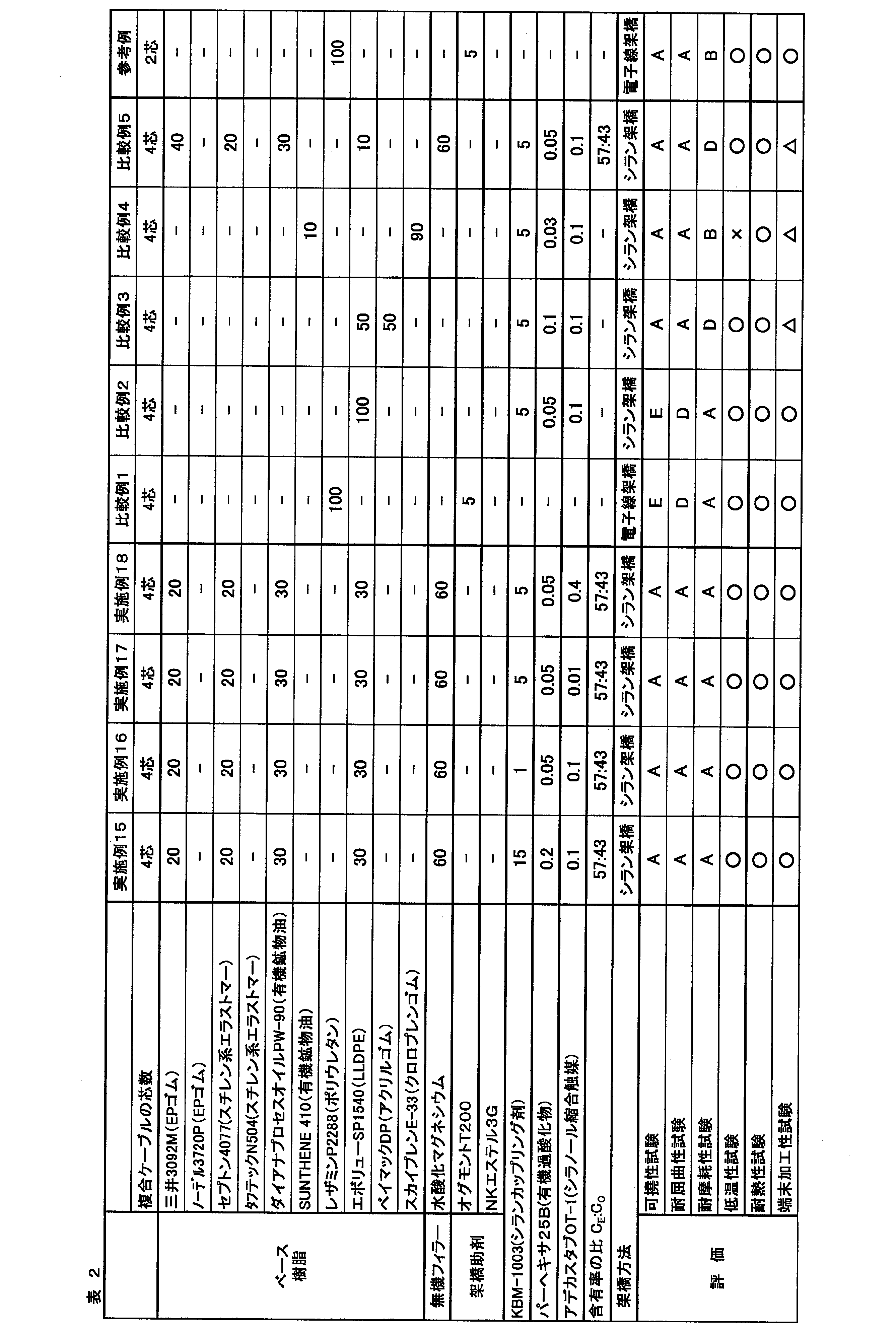
表1及び表2に示されるように、エチレンゴム及びスチレン系エラストマーの少なくとも1種を10~50質量%で含有するベース樹脂を含む樹脂組成物で形成されたシースを導体コアの外面に備えていると、複合ケーブルは、耐摩耗性、低温性、可撓性及び耐屈曲性を高い水準で兼ね備えていることが分かる。
すなわち、エチレンゴム及びスチレン系エラストマー以外の樹脂又はゴム(ポリウレタン、アクリルゴム又はクロロプレンゴム)を含むベース樹脂を用いると、上記4特性のいずれかが劣り、十分な特性を示さない。なお、参考例のABSケーブルは外径5mmで小径であるため、可撓性試験及び耐屈曲性試験に合格しているが、これと同じ材料でシースを形成した比較例1の複合ケーブル(外径8mm)は可撓性及び耐屈曲試験のいずれも不合格となり、特性の低下が著しい。
これに対して、エチレンゴム及びスチレン系エラストマーを特定量で含むベース樹脂を用いると、複合化により外径が8mmと大径化していても、上記4特性を優れたレベルに改善できる。とりわけ樹脂組成物の架橋物、特にシラン架橋物でシースを形成すると、上記4特性を更に高いレベルで兼ね備え、しかも高い耐熱性を示す複合ケーブルとすることができる。
本発明をその実施態様とともに説明したが、我々は特に指定しない限り我々の発明を説明のどの細部においても限定しようとするものではなく、添付の請求の範囲に示した発明の精神と範囲に反することなく幅広く解釈されるべきであると考える。
本願は、2019年3月27日に日本国で特許出願された特願2019-061382に基づく優先権を主張するものであり、これはここに参照してその内容を本明細書の記載の一部として取り込む。
1 複合ケーブル
2 太径電線
21 導体
22 樹脂層
3 細径電線
31 導体
32 樹脂層
4 シース
51、52 マンドレル
61、62 揺れ防止用の押え
7 おもり
102 ケーブル
2 太径電線
21 導体
22 樹脂層
3 細径電線
31 導体
32 樹脂層
4 シース
51、52 マンドレル
61、62 揺れ防止用の押え
7 おもり
102 ケーブル
Claims (8)
- 導体の外周に樹脂層を有する、複数の太径電線と、導体の外周に樹脂層を有する、複数の細径電線とから少なくともなるコアの外面を囲繞するシースを備えた複合ケーブルであって、
前記シースが、エチレンゴム及びスチレン系エラストマーの少なくとも1種を10~50質量%含有するベース樹脂を含む樹脂組成物からなる、複合ケーブル。 - 前記シースが、前記樹脂組成物の架橋物からなる請求項1に記載の複合ケーブル。
- 前記ベース樹脂が、有機鉱物油を含有する請求項1又は2に記載の複合ケーブル。
- 前記エチレンゴム及びスチレン系エラストマーの含有率(CE)と前記有機鉱物油の含有率(CO)との比(CE:CO)が、50:50~75:25である請求項3に記載の複合ケーブル。
- 前記樹脂組成物が、ベース樹脂100質量部に対して無機フィラーを10~150質量部含有している請求項1~4のいずれか1項に記載の複合ケーブル。
- 前記無機フィラーが、シリカ、水酸化アルミニウム、水酸化マグネシウム、炭酸カルシウム及び三酸化アンチモンからなる群から選択される少なくとも1種である請求項5に記載の複合ケーブル。
- 前記複合ケーブルが、車両のブレーキ制御用である、請求項1~6のいずれか1項に記載の複合ケーブル。
- 前記複数の太径電線のうちの2本が、電動パーキングブレーキの制御デバイスからアクチュエータに電力を供給する一対の電源線として、
前記複数の細径電線のうちの2本が、アンチロックブレーキシステムセンサからアンチロックブレーキシステム制御デバイスに信号を送信する一対の信号線として用いられる、
請求項7に記載の複合ケーブル。
Priority Applications (1)
| Application Number | Priority Date | Filing Date | Title |
|---|---|---|---|
| US17/483,955 US11810692B2 (en) | 2019-03-27 | 2021-09-24 | Composite cable |
Applications Claiming Priority (2)
| Application Number | Priority Date | Filing Date | Title |
|---|---|---|---|
| JP2019061382A JP7166973B2 (ja) | 2019-03-27 | 2019-03-27 | 複合ケーブル |
| JP2019-061382 | 2019-03-27 |
Related Child Applications (1)
| Application Number | Title | Priority Date | Filing Date |
|---|---|---|---|
| US17/483,955 Continuation US11810692B2 (en) | 2019-03-27 | 2021-09-24 | Composite cable |
Publications (1)
| Publication Number | Publication Date |
|---|---|
| WO2020196048A1 true WO2020196048A1 (ja) | 2020-10-01 |
Family
ID=72610142
Family Applications (1)
| Application Number | Title | Priority Date | Filing Date |
|---|---|---|---|
| PCT/JP2020/011518 Ceased WO2020196048A1 (ja) | 2019-03-27 | 2020-03-16 | 複合ケーブル |
Country Status (3)
| Country | Link |
|---|---|
| US (1) | US11810692B2 (ja) |
| JP (1) | JP7166973B2 (ja) |
| WO (1) | WO2020196048A1 (ja) |
Families Citing this family (5)
| Publication number | Priority date | Publication date | Assignee | Title |
|---|---|---|---|---|
| JP7665942B2 (ja) | 2020-09-25 | 2025-04-22 | 住友金属鉱山株式会社 | リチウムイオン二次電池用正極活物質およびその製造方法、リチウムイオン二次電池 |
| JP2023064842A (ja) * | 2021-10-27 | 2023-05-12 | 株式会社プロテリアル | 電線及びケーブル |
| JP2023111123A (ja) * | 2022-01-31 | 2023-08-10 | 古河電気工業株式会社 | 複合ケーブル |
| CN118475990A (zh) * | 2022-02-01 | 2024-08-09 | 住友电气工业株式会社 | 线缆 |
| JP2024138584A (ja) * | 2023-03-27 | 2024-10-09 | 古河電気工業株式会社 | 複合ケーブル |
Citations (4)
| Publication number | Priority date | Publication date | Assignee | Title |
|---|---|---|---|---|
| JP2013237428A (ja) * | 2012-04-20 | 2013-11-28 | Hitachi Cable Ltd | 複合ハーネス |
| JP2017145307A (ja) * | 2016-02-16 | 2017-08-24 | 古河電気工業株式会社 | 耐熱性シラン架橋樹脂成形体及び耐熱性シラン架橋性樹脂組成物とそれらの製造方法、シランマスターバッチ、並びに、耐熱性製品 |
| JP2017145370A (ja) * | 2016-02-19 | 2017-08-24 | 古河電気工業株式会社 | シラン架橋樹脂成形体及びシラン架橋性樹脂組成物とそれらの製造方法、シランマスターバッチ、並びに、成形品 |
| JP2018178029A (ja) * | 2017-04-19 | 2018-11-15 | 古河電気工業株式会社 | シラン架橋用触媒組成物、シラン架橋樹脂成形体調製用キット及びシラン架橋樹脂成形体の製造方法 |
Family Cites Families (7)
| Publication number | Priority date | Publication date | Assignee | Title |
|---|---|---|---|---|
| JPS54167385U (ja) * | 1978-05-17 | 1979-11-26 | ||
| JP3935320B2 (ja) * | 2001-01-19 | 2007-06-20 | 住友電装株式会社 | 樹脂組成物、その製法およびそれにより被覆された電線 |
| JP4816719B2 (ja) * | 2008-12-16 | 2011-11-16 | 住友電気工業株式会社 | 難燃ケーブル |
| JP2014009238A (ja) * | 2012-06-27 | 2014-01-20 | Furukawa Electric Co Ltd:The | 耐熱性樹脂組成物、当該耐熱性樹脂組成物を有する配線材、ケーブル及び成形品 |
| JP2016110836A (ja) | 2014-12-05 | 2016-06-20 | 矢崎総業株式会社 | キャブタイヤケーブル、及び、コネクタ付ケーブル |
| JP6219263B2 (ja) * | 2014-12-22 | 2017-10-25 | 日立金属株式会社 | 車両用複合ケーブル及び車両用複合ハーネス |
| JP6830297B2 (ja) * | 2016-02-15 | 2021-02-17 | 古河電気工業株式会社 | ケーブル |
-
2019
- 2019-03-27 JP JP2019061382A patent/JP7166973B2/ja active Active
-
2020
- 2020-03-16 WO PCT/JP2020/011518 patent/WO2020196048A1/ja not_active Ceased
-
2021
- 2021-09-24 US US17/483,955 patent/US11810692B2/en active Active
Patent Citations (4)
| Publication number | Priority date | Publication date | Assignee | Title |
|---|---|---|---|---|
| JP2013237428A (ja) * | 2012-04-20 | 2013-11-28 | Hitachi Cable Ltd | 複合ハーネス |
| JP2017145307A (ja) * | 2016-02-16 | 2017-08-24 | 古河電気工業株式会社 | 耐熱性シラン架橋樹脂成形体及び耐熱性シラン架橋性樹脂組成物とそれらの製造方法、シランマスターバッチ、並びに、耐熱性製品 |
| JP2017145370A (ja) * | 2016-02-19 | 2017-08-24 | 古河電気工業株式会社 | シラン架橋樹脂成形体及びシラン架橋性樹脂組成物とそれらの製造方法、シランマスターバッチ、並びに、成形品 |
| JP2018178029A (ja) * | 2017-04-19 | 2018-11-15 | 古河電気工業株式会社 | シラン架橋用触媒組成物、シラン架橋樹脂成形体調製用キット及びシラン架橋樹脂成形体の製造方法 |
Also Published As
| Publication number | Publication date |
|---|---|
| US20220013252A1 (en) | 2022-01-13 |
| JP2020161397A (ja) | 2020-10-01 |
| JP7166973B2 (ja) | 2022-11-08 |
| US11810692B2 (en) | 2023-11-07 |
Similar Documents
| Publication | Publication Date | Title |
|---|---|---|
| JP7086025B2 (ja) | 複合ケーブル及びその製造方法 | |
| JP6767438B2 (ja) | 耐熱性シラン架橋樹脂成形体及びその製造方法、耐熱性シラン架橋性樹脂組成物及びその製造方法、シランマスターバッチ、並びに耐熱性シラン架橋樹脂成形体を用いた耐熱性製品 | |
| JP6391580B2 (ja) | 耐熱性シラン架橋樹脂成形体及びその製造方法、耐熱性シラン架橋性樹脂組成物及びその製造方法、シランマスターバッチ、並びに耐熱性シラン架橋樹脂成形体を用いた耐熱性製品 | |
| JP7166973B2 (ja) | 複合ケーブル | |
| WO2016056635A1 (ja) | 架橋樹脂成形体及び架橋性樹脂組成物とそれらの製造方法、シランマスターバッチ、並びに、成形品 | |
| JP6858115B2 (ja) | シラン架橋性ゴム組成物及びシラン架橋ゴム成形体の製造方法 | |
| JP2015086385A (ja) | 耐熱性シラン架橋樹脂成形体及びその製造方法、耐熱性シラン架橋性樹脂組成物及びその製造方法、シランマスターバッチ、並びに耐熱性シラン架橋樹脂成形体を用いた耐熱性製品 | |
| JPWO2018180689A1 (ja) | 難燃性架橋樹脂成形体及びその製造方法、シランマスターバッチ、マスターバッチ混合物及びその成形体、並びに、難燃性製品 | |
| JP6800081B2 (ja) | シラン架橋樹脂成形体調製用キット及びシラン架橋樹脂成形体の製造方法 | |
| JP2019116583A (ja) | 耐熱性シラン架橋樹脂成形体及びその製造方法、並びに、耐熱性シラン架橋樹脂成形体を用いた耐熱性製品 | |
| JP2020161447A (ja) | キャブタイヤケーブル、キャブタイヤケーブル用絶縁電線及びこれらの製造方法 | |
| WO2016056634A1 (ja) | 難燃性架橋樹脂成形体及び難燃性架橋性樹脂組成物とそれらの製造方法、難燃性シランマスターバッチ、並びに、成形品 | |
| JP6395745B2 (ja) | シラン架橋樹脂成形体及びシラン架橋性樹脂組成物とそれらの製造方法、シランマスターバッチ、並びに、成形品 | |
| JP6738799B2 (ja) | シラン架橋性ゴム組成物及びシラン架橋ゴム成形体の製造方法 | |
| JP6325413B2 (ja) | 架橋樹脂成形体及び架橋性樹脂組成物とそれらの製造方法、シランマスターバッチ、並びに、成形品 | |
| JP2019116581A (ja) | シラン架橋用触媒組成物、シラン架橋性樹脂組成物及び配線材 | |
| JP6614937B2 (ja) | 半導電性シラン架橋樹脂成形体及び半導電性シラン架橋性樹脂組成物とそれらの製造方法、シランマスターバッチ、並びに、成形品 | |
| JP6782222B2 (ja) | シラン架橋アクリルゴム成形体及びその製造方法、シラン架橋性アクリルゴム組成物、並びに耐油性製品 | |
| JP2020143185A (ja) | シラン架橋用触媒組成物、シラン架橋樹脂成形体調製用キット及びシラン架橋樹脂成形体の製造方法 | |
| JP7593857B2 (ja) | 難燃性ポリオレフィン樹脂組成物及びこれを用いた配線材 | |
| JP6688634B2 (ja) | シラン架橋性ゴム組成物及びシラン架橋ゴム成形体とそれらの製造方法、並びに、シラン架橋ゴム成形品 | |
| JP6462606B2 (ja) | 耐熱性シラン架橋樹脂成形体及び耐熱性シラン架橋性樹脂組成物とそれらの製造方法、シランマスターバッチ、並びに、耐熱性製品 | |
| JP6928627B2 (ja) | 絶縁電線、キャブタイヤケーブル、及びこれらの製造方法 | |
| JP2024138584A (ja) | 複合ケーブル | |
| JP6523513B2 (ja) | 架橋樹脂成形体及び架橋性樹脂組成物とそれらの製造方法、シランマスターバッチ、並びに、成形品 |
Legal Events
| Date | Code | Title | Description |
|---|---|---|---|
| 121 | Ep: the epo has been informed by wipo that ep was designated in this application |
Ref document number: 20776319 Country of ref document: EP Kind code of ref document: A1 |
|
| NENP | Non-entry into the national phase |
Ref country code: DE |
|
| 122 | Ep: pct application non-entry in european phase |
Ref document number: 20776319 Country of ref document: EP Kind code of ref document: A1 |