WO2020195601A1 - トラクタ - Google Patents
トラクタ Download PDFInfo
- Publication number
- WO2020195601A1 WO2020195601A1 PCT/JP2020/008856 JP2020008856W WO2020195601A1 WO 2020195601 A1 WO2020195601 A1 WO 2020195601A1 JP 2020008856 W JP2020008856 W JP 2020008856W WO 2020195601 A1 WO2020195601 A1 WO 2020195601A1
- Authority
- WO
- WIPO (PCT)
- Prior art keywords
- state
- work machine
- tractor
- control device
- speed side
- Prior art date
- Legal status (The legal status is an assumption and is not a legal conclusion. Google has not performed a legal analysis and makes no representation as to the accuracy of the status listed.)
- Ceased
Links
Images


Classifications
-
- A—HUMAN NECESSITIES
- A01—AGRICULTURE; FORESTRY; ANIMAL HUSBANDRY; HUNTING; TRAPPING; FISHING
- A01B—SOIL WORKING IN AGRICULTURE OR FORESTRY; PARTS, DETAILS, OR ACCESSORIES OF AGRICULTURAL MACHINES OR IMPLEMENTS, IN GENERAL
- A01B63/00—Lifting or adjusting devices or arrangements for agricultural machines or implements
- A01B63/02—Lifting or adjusting devices or arrangements for agricultural machines or implements for implements mounted on tractors
- A01B63/10—Lifting or adjusting devices or arrangements for agricultural machines or implements for implements mounted on tractors operated by hydraulic or pneumatic means
Definitions
- the present invention mainly relates to a tractor to which a working machine can be attached.
- Patent Document 1 discloses a halo for puddling, which is a working machine of this type.
- the halo for scratching in Patent Document 1 includes a central working portion and side working portions arranged on the left and right sides of the central working portion.
- the side working portion is configured to be foldable inward in the left-right direction.
- the work machine when using this kind of retractable work machine, the work machine is used (for example, the side work part of the halo is expanded) and the work is performed in the field. After that, when returning after finishing the work in the field, the work machine is retracted (for example, the side work part of the halo is folded) and the work is carried out outside the field. Therefore, if the operator forgets to store the work equipment, the tractor may travel outside the field while the work equipment is in use.
- the present invention has been made in view of the above circumstances, and a main object thereof is to provide a tractor that cannot travel outside the field unless the working machine is stored.
- a tractor having the following configuration.
- This tractor includes a vehicle body, a communication unit, a work equipment elevating unit, and a control device.
- the vehicle body can be equipped with a work machine whose state can be changed between a retracted state and a used state.
- the communication unit receives from the work machine whether the work machine is in the stored state or the use state.
- the work machine elevating part raises and lowers the work machine between the ascending position and the descending position.
- the control device receives that the working machine is in the retracted state, and permits the running outside the field when the working machine is in the ascending position.
- the tractor described above preferably has the following configuration. That is, this tractor includes an auxiliary transmission that can switch the shifting state to at least the low speed side and the high speed side.
- the control device receives that the working machine is in the retracted state, and when the working machine is in the ascending position, the auxiliary transmission permits traveling on the high speed side.
- the tractor described above preferably has the following configuration. That is, this tractor includes an auxiliary transmission that can switch the shifting state to at least the low speed side and the high speed side.
- the control device maintains the auxiliary shift on the low speed side until it receives that the working machine has switched to the retracted state.
- the auxiliary transmission is maintained on the low speed side, so that the operator can be made aware that he / she has forgotten to store the work equipment.
- the tractor described above preferably has the following configuration. That is, the working machine is a halo for scraping.
- the stored state is a state in which a part of the tillage portion of the halo is stored.
- the used state is a state in which the cultivated portion stored in the stored state can be used.
- the tractor described above preferably has the following configuration. That is, this tractor includes a display unit that displays information about the working machine. If the control device does not receive from the work machine that the work machine has switched to the retracted state even if the elapsed time after detecting that the work machine is in the ascending position exceeds the threshold value, Information on switching from the used state of the working machine to the stored state is displayed on the display unit.
- the tractor described above preferably has the following configuration. That is, this tractor includes an auxiliary transmission device, an auxiliary transmission operation tool, and a display unit.
- the auxiliary transmission can switch the shifting state at least between the low speed side and the high speed side.
- the auxiliary transmission operating tool can be operated to switch the auxiliary transmission.
- the display unit displays information about the working machine. In the case where the working machine is in the used state, the control device switches from the used state of the working machine to the stored state when the auxiliary transmission tool instructs the switching to the high speed side. Information about the above is displayed on the display unit.
- the side view which shows the tractor and the working machine which concerns on one Embodiment of this invention.
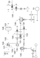
- Power transmission diagram of the tractor The rear view which shows the retracted state and the used state of a work machine.
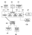
- the block diagram which shows the structure for performing the traveling prohibition control.
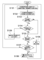
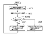
- a flowchart showing a running prohibition control The figure which shows the setting of the work machine and the warning message shown on the sub-display.
- FIG. 1 is a side view showing a tractor 10 and a working machine 3 according to an embodiment of the present invention.
- FIG. 1 shows an example in which a halo for scraping is used as the working machine 3.
- the terms "left side”, “right side”, and the like mean the left side and the right side in the direction in which the tractor 10 advances.
- the tractor 10 includes a vehicle body 11, a pair of left and right front wheels 12, and a pair of left and right rear wheels 13.
- a bonnet 14 is arranged at the front portion of the vehicle body 11, and an engine 15 is arranged inside the bonnet 14.
- a mission case 16 is arranged between the pair of left and right rear wheels 13.
- the output of the engine 15 is changed by a hydraulic transmission 120 or the like, which will be described later, arranged in the transmission case 16 and transmitted to the front wheels 12 and the rear wheels 13.
- lower links 18 are arranged in pairs on the left and right, and one top link 19 is arranged. Further, the PTO shaft 20 is arranged so as to project from the rear portion of the mission case 16.
- the work machine 3 is connected to the lower link 18 and the top link 19 and is driven by the PTO shaft 20.
- a work machine elevating mechanism 25 At the rear of the vehicle body 11, a work machine elevating mechanism 25, a work machine angle changing mechanism 26, and a connecting member 28 are provided.
- the work equipment elevating mechanism 25 includes a pair of left and right lift arms 21 and a lift cylinder (working equipment elevating part) 22 configured as a hydraulic cylinder.
- the tip of one of the left and right lift arms 21 is connected to one lower link 18 via a link member 23, and the tip of the other lift arm 21 is connected to the other lower link 18 via a rolling cylinder 24 described later. It is connected. With this configuration, the height at which the work machine 3 is supported by the vehicle body 11 can be changed by driving the lift cylinder 22.
- the work machine angle changing mechanism 26 includes a rolling cylinder 24 configured as a hydraulic cylinder.
- the rolling cylinder 24 is arranged so as to connect the lift arm 21 on the right side of the pair on the left and right and the lower link 18 on the right side. With this configuration, by driving the rolling cylinder 24, it is possible to change the tilting posture of the working machine 3 in the left-right direction supported by the vehicle body 11.
- the connecting member 28 is a member for connecting the lower link 18, the top link 19, and the working machine 3.
- a cabin 31 for an operator to board is arranged above the mission case 16 and behind the bonnet 14. Inside the cabin 31, a meter panel 36 capable of displaying a traveling speed, an engine rotation speed, a state of a working machine, a warning light, and the like is provided. In addition, these information may be displayed on the sub-display (display unit) 37 arranged in the cabin 31.
- a driver's seat 32 is provided inside the cabin 31, and various operating tools are provided in the vicinity of the driver's seat 32. Specifically, a steering wheel 33, an auxiliary transmission lever (auxiliary transmission operation tool) 34, and a reverser lever 35 are arranged in the vicinity of the driver's seat 32.
- the steering handle 33 is an operating tool for the operator to steer.
- the auxiliary shift lever 34 is an operating tool for instructing, for example, one of two stages (low speed side and high speed side).
- the operator specifies a rough speed with the auxiliary shift lever 34, and then specifies a fine speed with the main shift lever (not shown).
- the auxiliary transmission may be switched to three or more steps.
- it is preferable that the three or more auxiliary gears are classified into either a gear for field work (low speed side) and a gear for traveling on the road (outside the field) (high speed side). (For example, in the case of 3 stages, low speed 1 stage, high speed 1 stage, high speed 2 stages, etc.).
- the reversal lever 35 is an operation tool for instructing, for example, forward, reverse, and neutral.
- the power of the engine 15 When instructed to move forward, the power of the engine 15 is transmitted to move the tractor 10 forward.
- neutral When neutral is indicated, engine power is not transmitted to the drive wheels.
- a hydraulic transmission (HST) 120 for appropriately shifting the power transmitted from the engine 15 is housed in the mission case 16.
- the power of the engine 15 is transmitted to the main shift input shaft 121 of the transmission case 16 via the output shaft of the engine 15 shown in FIG. 2, and is appropriately shifted by the hydraulic transmission 120 and the traveling transmission mechanism, and the front wheels 12 and It is transmitted to the rear wheel 13.
- the hydraulic transmission 120 is configured to include a hydraulic pump 124 and a hydraulic motor 126 that are interconnected by a hydraulic pipe.
- the hydraulic pump 124 is driven by the main shift input shaft 121, while the hydraulic motor 126 drives the first sub-transmission shaft 131.
- One of the hydraulic pump 124 and the hydraulic motor 126 is a fixed capacity type, and the other is a variable capacity type.
- the hydraulic motor 126 is of the fixed capacity type and the hydraulic pump 124 is of the variable capacity type, and the amount of oil (discharge amount) discharged by the hydraulic pump 124 can be changed.
- the hydraulic motor 126 may be a variable capacity type, and the hydraulic pump 124 may be a fixed capacity type.
- the hydraulic pump 124 is provided with a movable swash plate 125 that changes the discharge amount according to the inclination angle.
- the tilt angle of the movable swash plate 125 changes when the operator performs a shift operation related to the main shift. Thereby, the rotation speed of the first sub-transmission shaft 131 can be changed.
- the main shift input shaft 121 is rotated by the power of the engine 15. Further, a first main transmission shaft 122 is connected to the main shift input shaft 121, and the first main transmission shaft 122 is configured to rotate integrally with the main shift input shaft 121.
- a PTO clutch 128 for switching whether to transmit or cut off power to the PTO shaft 20 is connected to the first main transmission shaft 122.
- the power of the engine 15 transmitted to the first main transmission shaft 122 is transmitted to the second main transmission shaft 123 via the PTO clutch 128.
- the power of the engine 15 transmitted to the second main transmission shaft 123 is output to the PTO shaft 20 after shifting and being transmitted via the PTO gear group 129. With this configuration, power can be transmitted to and driven by the working machine 3 mounted on the tractor 10.
- a first sub-transmission shaft 131 and a front wheel transmission shaft 133 are further arranged in the vicinity of the hydraulic transmission 120.
- the first sub-transmission shaft 131 is arranged so as to project from the hydraulic motor 126, and the rotation that is steplessly changed by the hydraulic transmission 120 is output to the first sub-transmission shaft 131.
- the auxiliary transmission 130 is connected to the first auxiliary transmission shaft 131.
- the sub-transmission device 130 is configured to shift the rotation of the first sub-transmission shaft 131 and transmit it to the second sub-transmission shaft 132.
- the rotation of the second sub-transmission shaft 132 is input to the rear wheel differential device 136, and drives the rear wheel 13 via the axle, transmission gear, and the like in the rear axle case.
- the rotation of the second sub-transmission shaft 132 is transmitted to the front wheel transmission shaft 133.
- the rotation of the front wheel transmission shaft 133 is input to the front wheel differential device 135, and drives the front wheel 12 via the axle, transmission gear, etc. in the front axle case.
- Working machine 3 is a halo for scraping. Scraping is the work of crushing the soil and flattening the surface of the rice field after pouring water into the rice field (field).
- the working machine 3 includes a connecting member 28 provided at the rear portion of the vehicle body 11 and a connecting portion 71 for connecting the working machine 3.
- the connecting portion 71 may be configured to be directly connected to the lower link 18 and the top link 19 without the need for the connecting member 28.
- a tillage cover 72 is provided behind the connecting member 28.
- a tillage rotation shaft 73 is rotatably attached to the tillage cover 72.
- the cultivated rotation shaft 73 rotates about the left-right direction as a rotation axis by the power transmitted from the PTO shaft 20 by the power transmission mechanism (not shown).
- a plurality of tilling claws 74 are connected to the tilling rotation shaft 73 side by side in the left-right direction. With this configuration, the soil of the rice field can be crushed by rotating the tilling claw 74 together with the tilling rotating shaft 73.
- a ground preparation plate 75 is arranged behind the tillage cover 72.
- the ground leveling plate 75 is attached to the tillage cover 72 so that it can rotate about the left-right direction as a rotation axis. Further, the ground leveling plate 75 is urged downward by an urging member (not shown). With this configuration, the field surface can be flattened.
- An extended ground leveling plate 76 for widening the ground leveling width is provided on the outside of the ground leveling plate 75 in the left-right direction.
- the working machine 3 is configured to be openable and closable. More specifically, the working machine 3 has a three-divided structure, and includes a central tillage portion 3a and left and right side tillage portions 3b.
- a tillage cover 72, a tillage rotation shaft 73, a tillage claw 74, and a ground preparation plate 75 are provided on each of the central tillage portion 3a and the side tillage portion 3b.
- the side tillage portion 3b is rotatably connected to the central tillage portion 3a via a rotation shaft member (not shown). Further, the central tillage portion 3a and the side tillage portion 3b are connected by an opening / closing cylinder 77.
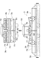
- the working machine 3 can switch between a retracted state (upper side of FIG. 3) and a used state (lower side of FIG. 3).
- the stored state is a state in which the two lateral tillage portions 3b are positioned above the central tillage portion 3a, that is, the two lateral tillage portions 3b are folded and stored.
- the used state is a state in which the two lateral tillage portions 3b are positioned on the outer side in the left-right direction of the central tillage portion 3a to widen the working width. Further, in the used state, after the lift cylinder 22 is operated to lower the working machine 3 (at the position of the two-dot chain line on the lower side of FIG. 3), the working machine 3 is used for the field.
- the working machine 3 is provided with a state detection sensor 81 and a ground level plate rotation angle sensor 82.
- the state detection sensor 81 is a sensor that detects whether or not the work machine 3 is in the retracted state or in the used state (in other words, whether or not the side tillage portion 3b is expanded).
- the state detection sensor 81 is a limit switch, and has a configuration in which when the side tillage portion 3b is in the retracted state, it comes into contact with any portion and energizes. Since the state detection sensors 81 are arranged in pairs on the left and right, the states of both the left and right side tillage portions 3b can be individually detected.
- the ground leveling plate rotation angle sensor 82 detects the rotation angle of the ground leveling plate 75 (in other words, how much the ground leveling plate 75 moves up and down during leveling).
- the ground leveling plate rotation angle sensor 82 is, for example, a potentiometer that detects the rotation angle of the ground leveling plate 75 or a link attached to the rotation shaft thereof. Based on the detection result of the ground level plate rotation angle sensor 82, for example, the degree of the size of the soil mass in the field after tilling can be detected. That is, when the soil mass remaining after plowing is large, the ground leveling plate rotation angle sensor 82 rotates greatly up and down. On the other hand, when the soil mass remaining after plowing is small, the ground level plate rotation angle sensor 82 rotates small up and down. Therefore, it is possible to obtain information on the size of the soil mass remaining in the field after plowing based on the magnitude and frequency of rotation of the ground level plate rotation angle sensor 82.
- the structure of the above two sensors is an example, and may have different structures.
- the state detection sensor 81 may be configured to detect the rotation angle of the rotation shaft of the side tillage portion 3b, or may be configured to detect the expansion / contraction length of the opening / closing cylinder 77.
- the tractor 10 includes a control device 50 for controlling the work machine 3.
- the control device 50 controls the operation, height, posture, and the like of the work machine 3.
- the control device 50 includes an arithmetic unit such as a CPU and a storage device including a ROM, RAM, and the like.
- the control device 50 can be used as a communication unit 51, a travel control unit 52, a work control unit 53, a display control unit 54, and the like. Can work.
- the detection value of the work equipment height sensor 41 is input to the control device 50.
- the work machine height sensor 41 is a sensor that detects the height of the work machine 3, for example, a sensor that detects the position of the cylinder rod of the lift cylinder 22 (the length of the lift cylinder 22).
- the communication unit 51 performs a process of communicating with the work machine side control device 80 provided in the work machine 3.
- the communication unit 51 may be configured to perform wired communication or may be configured to perform wireless communication.
- the control device 50 can receive information from the work machine side control device 80.
- the information received by the control device 50 includes, for example, the type of the work machine 3 (rotary, halo, etc.), the special function of the work machine 3 (for example, the presence / absence of the storage function, etc.), the detection value of the state detection sensor 81, and the adjustment. It is a detection value of the main plate rotation angle sensor 82 and the like.
- the work machine side control device 80 determines whether the work machine 3 is in the retracted state or the use state, and transmits the determination result to the control device 50. You may.
- the travel control unit 52 controls the travel of the tractor 10.
- the travel control unit 52 controls, for example, to prohibit the tractor 10 from traveling under certain conditions.
- the travel control unit 52 prohibits the travel of the tractor 10 by, for example, operating an actuator (not shown) to neutralize the movable swash plate 125 (a state in which power is not transmitted).
- the travel control unit 52 may prohibit the tractor 10 from traveling by operating the brake, or may disengage the clutch so that power is not transmitted from the engine 15 to the front wheels 12 and the rear wheels 13.
- the running of the tractor 10 may be prohibited.
- the travel control unit 52 can also control to change the vehicle speed in response to an operator's instruction or autonomously.
- the travel control unit 52 changes the vehicle speed of the tractor 10 by changing the rotation angle of the movable swash plate 125, for example.
- the work control unit 53 controls a solenoid valve arranged between the lift cylinder 22 and the hydraulic pump to change the height (work machine height) at which the work machine 3 is supported by the vehicle body 11. I do. Further, the height of the working machine is mainly divided into a descending position, which is the height when working on the field, and an ascending position, which is higher than the descending position and is mainly the height of the working machine 3 during traveling. be able to. Further, the work control unit 53 also controls to change the tilting posture of the work machine 3 in the left-right direction by controlling the solenoid valve arranged between the rolling cylinder 24 and the hydraulic pump.
- the display control unit 54 controls, for example, to display information about the work machine 3 on the sub-display 37 or the like.
- the communication unit 51 of the control device 50 communicates with the work machine side control device 80 immediately after mounting the work machine 3, for example, and the work machine 3 is a halo for scraping (type of work machine). It receives that the work machine 3 has a storage function (presence or absence of the storage function) (S101).
- the communication unit 51 of the control device 50 acquires the open / closed state of the work machine 3 from the work machine side control device 80 (S102).
- the open / closed state is whether the working machine 3 is in the stored state or the used state, in other words, whether or not the side tillage portion 3b is stored.
- the information acquired by the control device 50 is the detected value of the state detection sensor 81 or the information obtained from the detected value.
- the control device 50 determines whether or not the work machine 3 is in the stored state based on the information acquired in step S102 (S103).
- the traveling control unit 52 of the control device 50 prohibits traveling on the high-speed side of the auxiliary transmission as described later. Further, the control device 50 determines whether or not the work equipment height is in the ascending position based on the work equipment height sensor 41 (S104), and the work equipment height is not in the ascending position (that is, in the descending position). ), The auxiliary shift prohibits driving on the high-speed side.
- the control device 50 determines whether or not the auxiliary transmission is on the high speed side based on the detection result of the sensor or the like that detects the position of the auxiliary transmission lever 34 (S105). Then, when it is determined that the auxiliary transmission is on the high speed side, the travel control unit 52 performs a travel prohibition process (S106). As described above, the travel prohibition process is a process for making the movable swash plate 125 neutral so that the tractor 10 cannot travel. The traveling prohibition process is continuously performed as long as the auxiliary transmission is on the high speed side. Further, when the auxiliary transmission is on the low speed side, the traveling prohibition process is not performed. In addition, in the determination of step S105, the condition that the reverser lever is in the forward position may be added.
- FIG. 6 shows an example in which the warning message 96 is displayed on the screen for displaying the information about the work machine.
- a display object 91 showing a tractor and a working machine, an inclination meter 92, and a reference setting button 93 are displayed.
- the tilt meter 92 indicates whether the work machine 3 is tilted to the left or right. Based on the detection result of the tilt sensor (not shown) provided on the tractor 10 or the work machine 3, for example, when it is determined that the work machine 3 is tilted to the left, the bar of the tilt meter 92 moves to the left. .. Further, by operating the reference setting button 93, the inclination meter 92 is adjusted so that the inclination of the working machine 3 at the time of operation is displayed as a reference state (horizontal state). On the sub-display 37, the depth meter 94 and the reference setting button 95 are displayed not only in the horizontal direction of the work equipment 3 but also in the depth direction.
- the display control unit 54 may display a warning message 96 on the screen. Further, the display control unit 54 may display a warning message 96 on the meter panel 36 in place of or in addition to the sub-display 37.
- the warning message 96 is displayed at the timing when the traveling prohibition process is performed, so that the operator can notice that the work machine 3 is in use. Further, even if the auxiliary transmission is on the low speed side, if the elapsed time after the height of the work equipment reaches the ascending position exceeds the threshold value (S107), the warning message 96 is similarly displayed. This is because it is difficult to assume that the work will be performed when the work machine 3 is raised to the raised position, and the operator is urged to return the work machine 3 to the retracted state.
- the tractor 10 cannot travel outside the field with the side tillage portion 3b of the working machine 3 expanded. Further, by displaying the warning message 96, the operator can notice that he / she has forgotten to store the work equipment 3.
- the control device 50 repeats the process shown in FIG. Then, when the work equipment is in the retracted state and the height of the work equipment is in the ascending position, traveling on the high speed side of the auxiliary transmission is permitted (S109). In this case, even if the auxiliary transmission is switched to the high speed side, the traveling prohibition process is not performed. This allows the tractor 10 to travel outside the field.
- the communication unit 51 of the control device 50 acquires a change in the rotation angle of the ground preparation plate 75 from the work machine side control device 80 (S201). As described above, information on the size of the soil mass remaining in the field after tilling can be obtained based on the magnitude and frequency of the change in the rotation angle of the ground preparation plate 75.
- the control device 50 estimates the size of the soil mass in the field after tilling based on the information acquired in step S201 (S202). As described above, the larger the size of the soil mass, the larger the change in the rotation angle of the ground preparation plate 75. When a large angle and a small angle are mixed in the rotation angle of the ground preparation plate 75, the average value of the size of the soil mass is estimated by, for example, calculating the average value.
- the control device 50 determines whether or not the size of the soil mass calculated in step S202 is equal to or greater than the threshold value (S203).
- the threshold value for example, a predetermined initial value is set from the time of shipment from the factory, and the operator can change the magnitude of the threshold value as needed.
- the control device 50 increases the PTO rotation speed by the work control unit 53 and the travel control unit 52. At least one of the vehicle speed reductions is performed (S204).
- a method of increasing the PTO rotation speed for example, there are a method of changing the shift stage of the device for shifting the PTO and a method of increasing the engine rotation speed. By increasing the PTO rotation speed, the rotation speed of the tilling claw 74 is increased, so that the tilling work can be performed more finely. Further, even when the vehicle speed is reduced, the number of times the tilling claw 74 acts per unit area increases, so that the tilling work can be performed more finely.
- control device 50 when the difference between the size of the soil mass and the threshold value is equal to or larger than a predetermined value, the control device 50 both increases the PTO rotation speed and decreases the vehicle speed to quickly and surely bring the size of the soil mass close to the threshold value. Processing may be performed.
- the tillage claw 74 may excessively cultivate the soil, so that the control device 50 reduces the PTO rotation speed by the work control unit 53 and the vehicle speed by the travel control unit 52. At least one of the rises in (S205). The effects of PTO rotation speed and vehicle speed on tillage are as described above.
- the control device 50 continuously performs the process shown in FIG. 7. That is, for example, when the size of the soil mass falls below the threshold value as a result of increasing the PTO rotation speed, the PTO rotation speed is decreased. As a result, the size of the soil mass can always be brought close to the threshold value.
- the threshold value for the size of the soil mass is one, but two threshold values, an upper limit threshold value and a lower limit threshold value, may be set. That is, when the size of the soil mass is equal to or greater than the lower limit threshold value and less than or equal to the upper limit threshold value, the PTO rotation speed and the vehicle speed are maintained. Further, when the size of the soil mass falls below the lower limit threshold value, the PTO rotation speed is lowered or the vehicle speed is increased. Further, when the size of the soil mass exceeds the upper limit threshold value, the PTO rotation speed is increased or the vehicle speed is decreased. This makes it difficult for the PTO rotation speed and vehicle speed to be changed frequently.
- the tractor 10 of the present embodiment includes a vehicle body 11, a communication unit 51, a lift cylinder 22, and a control device 50.
- the vehicle body 11 can be equipped with a work machine 3 whose state can be changed between the retracted state and the used state.
- the communication unit 51 receives from the work machine 3 whether the work machine 3 is in the stored state or the used state.
- the lift cylinder 22 raises and lowers the work machine 3 between the ascending position and the descending position.
- the control device 50 receives that the work machine 3 is in the retracted state, and permits the work machine 3 to travel outside the field when the work machine 3 is in the ascending position.
- the state of the work machine 3 can be specified on the tractor 10 side. As a result, it is possible to realize a configuration in which traveling outside the field is permitted only when the working machine 3 is in the retracted state.
- the tractor 10 of the present embodiment includes an auxiliary transmission 130 capable of switching the shifting state at least between the low speed side and the high speed side.
- the control device 50 receives that the working machine 3 is in the retracted state, and when the working machine 3 is in the ascending position, the auxiliary shift permits the traveling on the high speed side.
- control device 50 of the tractor 10 may be configured to maintain the auxiliary shift on the low speed side until the work machine 3 is switched to the retracted state.
- auxiliary transmission lever 34 by providing a structure that can regulate the movement of the auxiliary transmission lever 34, it is possible to realize a configuration in which the auxiliary transmission lever 34 cannot move to the high speed side (maintain at the low speed side).
- auxiliary transmission lever 34 by adopting a structure in which the instruction of the auxiliary transmission is electrically transmitted, it is possible to prevent the auxiliary transmission from being switched even if the operator operates so that the auxiliary transmission is on the high speed side. ..
- the auxiliary transmission is maintained on the low speed side, so that the operator can be made aware that he / she has forgotten to store the work machine 3.
- the working machine 3 is a halo for scraping.
- the stored state is a state in which a part of the cultivated portion of the halo (side cultivated portion 3b) is stored.
- the used state is a state in which the cultivated portion (side cultivated portion 3b) stored in the stored state can be used.
- the tractor 10 of the present embodiment includes a sub-display 37 that displays information about the work machine 3. If the control device 50 does not receive from the work machine that the work machine 3 has been switched to the retracted state even if the elapsed time after detecting that the work machine 3 is in the ascending position exceeds the threshold value, the work machine 50 Information on switching from the used state to the stored state of 3 is displayed on the sub-display 37.
- the control device 50 when the working machine 3 is in the working state, the control device 50 starts from the working state of the working machine 3 when the auxiliary shift lever 34 instructs the switching to the high speed side. Information on switching to the stored state is displayed on the sub-display 37.
- the tractor 10 in addition to displaying the warning message 96, the tractor 10 is physically prohibited from traveling by setting the movable swash plate 125 to neutral. Instead of this, for example, only the process of displaying the warning message 96 may be performed to prohibit the operator from traveling on the tractor 10.
- the flowchart shown in the above embodiment is an example, and some processes may be omitted, the contents of some processes may be changed, or new processes may be added. For example, the process of step S107 in FIG. 5 may be omitted.
- the warning message 96 is displayed after the auxiliary transmission is on the high speed side (S105), but instead of this, traveling outside the field is prohibited after the conditions of steps S103 and S104 are satisfied. A message indicating that the transmission has been performed (the auxiliary transmission cannot be set to the high speed side) may be displayed.
- the warning message 96 of the above embodiment is an example, and different contents may be displayed. For example, it may be further displayed that the vehicle cannot travel outside the field, the auxiliary transmission cannot be set to the high speed side, and the like.
- a halo for scraping is used as the work machine 3
- the work machine is a work machine capable of switching between a stored state and a use state and works in a lowered position, other than the halo.
- the present invention can also be applied to the working machine of.
Landscapes
- Life Sciences & Earth Sciences (AREA)
- Engineering & Computer Science (AREA)
- Mechanical Engineering (AREA)
- Soil Sciences (AREA)
- Environmental Sciences (AREA)
- Lifting Devices For Agricultural Implements (AREA)
- Agricultural Machines (AREA)
Abstract
トラクタは、車体と、通信部と、リフトシリンダと、制御装置と、を備える。車体は、格納状態と使用状態の間で状態を変更可能な作業機を取付可能である。通信部は、作業機が格納状態か使用状態の何れの状態であるかを当該作業機から受信する。リフトシリンダは、作業機を上昇位置と下降位置との間で昇降する。制御装置は、作業機が格納状態であることを受信し、かつ、作業機が上昇位置である場合に、圃場外での走行を許可する。
Description
本発明は、主として、作業機を取付可能なトラクタに関する。
トラクタに取り付けられる作業機の中には、格納状態と使用状態を切替可能なものが知られている。特許文献1には、この種の作業機である代掻き用のハローが開示されている。
特許文献1の代掻き用のハローは、中央作業部と、中央作業部の左右両側に配置されるサイド作業部と、を備える。サイド作業部は、左右方向の内側に折り畳み可能に構成されている。
ここで、この種の格納可能な作業機を用いる場合は、作業機を使用状態にして(例えばハローのサイド作業部を広げて)圃場で作業を行う。その後、圃場での作業を終えて帰還する場合は、作業機を格納状態にして(例えばハローのサイド作業部を折り畳んで)圃場外を走行する。そのため、オペレータが作業機を格納状態にすることを忘れた場合、作業機が使用状態のままトラクタが圃場外を走行する可能性がある。
本発明は以上の事情に鑑みてされたものであり、その主要な目的は、作業機を格納状態にしないと圃場外を走行できないトラクタを提供することにある。
本発明の解決しようとする課題は以上の如くであり、次にこの課題を解決するための手段とその効果を説明する。
本発明の観点によれば、以下の構成のトラクタが提供される。このトラクタは、車体と、通信部と、作業機昇降部と、制御装置と、を備える。前記車体は、格納状態と使用状態の間で状態を変更可能な作業機を取付可能である。前記通信部は、前記作業機が前記格納状態と前記使用状態の何れの状態であるかを当該作業機から受信する。前記作業機昇降部は、前記作業機を上昇位置と下降位置との間で昇降する。前記制御装置は、前記作業機が前記格納状態であることを受信し、かつ、前記作業機が前記上昇位置である場合に、圃場外での走行を許可する。
このように、作業機が使用状態か格納状態かの情報を作業機から受信することで、トラクタ側で作業機の状態を特定できる。これにより、作業機を格納状態にした場合のみで圃場外の走行が許可される構成が実現できる。
前記のトラクタにおいては、以下の構成とすることが好ましい。即ち、このトラクタは、少なくとも低速側と高速側に変速状態を切替可能な副変速装置を備える。前記制御装置は、前記作業機が前記格納状態であることを受信し、かつ、前記作業機が前記上昇位置である場合に、副変速が前記高速側での走行を許可する。
これにより、圃場外を走行する場合は副変速の高速側を用いるため、作業機を使用状態にしての圃場外の走行をより確実に禁止できる。
前記のトラクタにおいては、以下の構成とすることが好ましい。即ち、このトラクタは、少なくとも低速側と高速側に変速状態を切替可能な副変速装置を備える。前記制御装置は、前記作業機が前記格納状態に切り替わったことを受信するまでは、副変速を前記低速側で維持する。
これにより、副変速が低速側で維持されるため、作業機の格納を忘れていることをオペレータに気付かせることができる。
前記のトラクタにおいては、以下の構成とすることが好ましい。即ち、前記作業機は代掻き用のハローである。前記格納状態は、前記ハローの耕耘部の一部が格納された状態である。前記使用状態は、前記格納状態で格納された耕耘部が使用可能となる状態である。
これにより、代掻き用のハローが広げられた状態で圃場外をトラクタが走行することを防止できる。
前記のトラクタにおいては、以下の構成とすることが好ましい。即ち、このトラクタは、前記作業機に関する情報を表示する表示部を備える。前記制御装置は、前記作業機が前記上昇位置であることを検出した後の経過時間が閾値以上となっても前記作業機が前記格納状態に切り替わったことを当該作業機から受信しない場合は、前記作業機の前記使用状態から前記格納状態への切替えに関する情報を前記表示部に表示する。
これにより、作業機の格納を忘れていることをオペレータに気付かせることができる。
前記のトラクタにおいては、以下の構成とすることが好ましい。即ち、このトラクタは、副変速装置と、副変速操作具と、表示部と、を備える。前記副変速装置は、少なくとも低速側と高速側に変速状態を切替可能である。前記副変速操作具は、前記副変速を切り替える操作が可能である。前記表示部は、前記作業機に関する情報を表示する。前記制御装置は、前記作業機が前記使用状態である場合において、前記副変速操作具により前記高速側への切替えが指示されたときに、前記作業機の前記使用状態から前記格納状態への切替えに関する情報を前記表示部に表示する。
これにより、走行が禁止される理由をオペレータに知らせることで、作業機を前記格納状態に戻すことをオペレータに促すことができる。
次に、図面を参照して発明の実施の形態について説明する。図1は、本発明の一実施形態に係るトラクタ10と作業機3を示す側面図である。
図1に示すトラクタ10は、ロータリ、ハロー、ローダ、プラウ、ボックススクレーパー等の各種の作業機3を必要に応じて車体11に装着し、車体11に支持された作業機3により各種の作業を行うことができる。図1では、作業機3として代掻き用のハローを用いた例が示されている。なお、以下の説明では、単に「左側」「右側」等というときは、トラクタ10が前進する方向に向かって左側及び右側を意味するものとする。
図1に示すように、トラクタ10は、車体11と、左右1対の前輪12と、左右1対の後輪13と、を備える。車体11の前部にはボンネット14が配置されており、当該ボンネット14の内部にはエンジン15が配置されている。
左右1対の後輪13の間には、ミッションケース16が配置されている。エンジン15の出力は、このミッションケース16内に配置された後述の油圧式変速装置120等によって変速されて、前輪12及び後輪13へ伝達される。
ミッションケース16の後部には、ロワーリンク18が左右1対で配置されるとともに、1つのトップリンク19が配置されている。更に、ミッションケース16の後部からPTO軸20が突出して配置されている。作業機3は、ロワーリンク18及びトップリンク19に連結され、PTO軸20によって駆動される。
車体11の後部には、作業機昇降機構25と、作業機角度変更機構26と、連結部材28と、が設けられている。
作業機昇降機構25は、左右1対のリフトアーム21と、油圧シリンダとして構成されるリフトシリンダ(作業機昇降部)22と、を備える。左右一方のリフトアーム21の先端部は、リンク部材23を介して一方のロワーリンク18に連結され、他方のリフトアーム21の先端部は、後述のローリングシリンダ24を介して他方のロワーリンク18に連結されている。この構成で、リフトシリンダ22を駆動することにより、作業機3が車体11に支持される高さを変更することができる。
作業機角度変更機構26は、油圧シリンダとして構成されるローリングシリンダ24を備える。ローリングシリンダ24は、左右1対のうち右側のリフトアーム21と、右側のロワーリンク18と、を連結するように配置される。この構成で、ローリングシリンダ24を駆動することにより、作業機3が車体11に対して支持される左右方向の傾斜姿勢を変更することができる。
連結部材28は、ロワーリンク18及びトップリンク19と、作業機3と、を連結するための部材である。
ミッションケース16の上方であってボンネット14の後方には、オペレータが搭乗するためのキャビン31が配置されている。キャビン31内には、走行速度、エンジン回転速度、作業機の状態、警告灯等を表示可能なメータパネル36が設けられている。なお、これらの情報は、キャビン31に配置されるサブディスプレイ(表示部)37に表示してもよい。
また、キャビン31の内部には運転座席32が設けられており、運転座席32の近傍には各種の操作具が設けられている。具体的に説明すると、運転座席32の近傍には、ステアリングハンドル33と、副変速レバー(副変速操作具)34と、リバーサレバー35と、が配置されている。
ステアリングハンドル33は、オペレータが操舵を行うための操作具である。副変速レバー34は、例えば2段階(低速側と高速側)の何れかを指示するための操作具である。オペレータは、副変速レバー34で大まかな速度を指定した後に、図略の主変速レバーを用いて細かい速度を指定する。なお、副変速は3段階以上に切替可能であってもよい。この場合、3以上の副変速段は、圃場作業用の変速段(低速側)と、路上(圃場外)の走行用の変速段(高速側)と、の何れかに区分されることが好ましい(例えば3段の場合、低速1段、高速1段、及び高速2段等)。リバーサレバー35は、例えば前進、後進、ニュートラルを指示するための操作具である。前進が指示された場合、トラクタ10を前進させるようにエンジン15の動力が伝達される。後進が指示された場合、トラクタ10を後進させるようにエンジン15の動力が伝達される。ニュートラルが指示された場合、エンジンの動力は駆動輪に伝達されない。
ミッションケース16内には、エンジン15から伝達される動力を適宜に変速するための油圧式変速装置(HST)120が収容される。エンジン15の動力は、図2に示すエンジン15の出力軸を経由してミッションケース16の主変速入力軸121に伝達され、油圧式変速装置120及び走行変速機構によって適宜変速されて、前輪12及び後輪13に伝達されるようになっている。
油圧式変速装置120は、油圧管によって相互に接続された油圧ポンプ124と油圧モータ126とを備えて構成されている。油圧ポンプ124は主変速入力軸121によって駆動される一方、油圧モータ126は第1副伝達軸131を駆動する。
油圧ポンプ124と油圧モータ126の一方は固定容量型とされ、他方は可変容量型とされている。本実施形態においては、油圧モータ126が固定容量型とされ、油圧ポンプ124が可変容量型とされており、当該油圧ポンプ124が吐出するオイルの量(吐出量)を変化させることができる。なお、油圧モータ126を可変容量型とし、油圧ポンプ124を固定容量型としても良い。
油圧ポンプ124には、傾斜角度に応じて吐出量を変化させる可動斜板125が設けられている。オペレータが主変速に関する変速操作を行うことで、この可動斜板125の傾斜角度が変化する。これにより、第1副伝達軸131の回転速度を変化させることができる。
主変速入力軸121は、エンジン15の動力により回転する。また、主変速入力軸121には第1主伝達軸122が連結され、この第1主伝達軸122は、主変速入力軸121と一体的に回転するように構成されている。
第1主伝達軸122には、PTO軸20へ動力を伝達するか遮断するかを切り替えるためのPTOクラッチ128が接続されている。第1主伝達軸122に伝達されたエンジン15の動力は、PTOクラッチ128を介して、第2主伝達軸123に伝達される。第2主伝達軸123に伝達されたエンジン15の動力は、PTOギア群129を介して変速及び伝達された後に、PTO軸20に出力される。この構成により、トラクタ10に装着された作業機3に動力を伝達して駆動することができる。
油圧式変速装置120の近傍には、更に、第1副伝達軸131及び前輪伝達軸133が配置される。第1副伝達軸131は油圧モータ126から突出するように配置され、この第1副伝達軸131には、油圧式変速装置120で無段階に変速された回転が出力される。
第1副伝達軸131には、副変速装置130が接続される。副変速装置130は、第1副伝達軸131の回転を変速して、第2副伝達軸132に伝達するように構成されている。第2副伝達軸132の回転は、後輪デフ装置136に入力され、後車軸ケース内の車軸、伝達歯車等を経由して後輪13を駆動する。
また、第2副伝達軸132の回転は、前輪伝達軸133に伝達される。前輪伝達軸133の回転は、前輪デフ装置135に入力され、前車軸ケース内の車軸、伝達歯車等を介して前輪12を駆動する。
作業機3は、代掻き用のハローである。代掻きとは、田(圃場)に水を入れた後に、土を砕くとともに田面を平らにする作業である。
図1に示すように、作業機3は、車体11の後部に設けれらた連結部材28と作業機3を連結するための連結部71を備える。連結部71は、連結部材28を介さずに、ロワーリンク18及びトップリンク19と直接接続できる構成であってもよい。
連結部材28の後方には、耕耘カバー72が設けられている。耕耘カバー72には、耕耘回転軸73が回転可能に取り付けられている。耕耘回転軸73は、図略の動力伝達機構により、PTO軸20から伝達された動力によって左右方向を回転軸として回転する。また、耕耘回転軸73には、左右方向に並べて複数の耕耘爪74が接続されている。この構成により、耕耘回転軸73ととも耕耘爪74が回転することで、田の土を砕くことができる。
耕耘カバー72の後方には、整地板75が配置されている。整地板75は、耕耘カバー72に対して、左右方向を回転軸として回転できるように取り付けられている。また、整地板75は、図略の付勢部材により下方に付勢されている。この構成により、田面を平らにすることができる。なお、整地板75の左右方向の外側には、整地幅を広げるための延長整地板76が設けられている。
また、図3に示すように、作業機3は開閉可能に構成されている。具体的に説明すると、作業機3は、3分割構造であり、中央耕耘部3aと、左右の側方耕耘部3bと、を備える。中央耕耘部3a及び側方耕耘部3bのそれぞれに、耕耘カバー72、耕耘回転軸73、耕耘爪74、及び整地板75が設けられている。側方耕耘部3bは、図略の回動軸部材を介して中央耕耘部3aに対して回動可能に接続されている。また、中央耕耘部3aと側方耕耘部3bは、開閉シリンダ77によって接続されている。開閉シリンダ77を伸縮させることで、作業機3は、格納状態(図3の上側)と、使用状態(図3の下側)と、の間で状態を切替可能である。格納状態とは、2つの側方耕耘部3bを中央耕耘部3aの上方に位置させて、即ち2つの側方耕耘部3bを折り畳んで格納させた状態である。使用状態とは、2つの側方耕耘部3bを中央耕耘部3aの左右方向外側に位置させて作業幅を広げた状態である。また、使用状態において、リフトシリンダ22を動作させて作業機3を下げた後に(図3の下側の2点鎖線の位置で)、圃場に対して作業機3による作業が行われる。
図3に示すように、作業機3には、状態検出センサ81と、整地板回転角センサ82と、が設けられている。
状態検出センサ81は、作業機3が格納状態にあるか使用状態にあるか否か(言い換えれ側方耕耘部3bが広げられているか否か)を検出するセンサである。状態検出センサ81は、リミットスイッチであり、側方耕耘部3bが格納状態になったときに何れかの部分と接触して通電する構成である。状態検出センサ81は、左右一対で配置されているため、左右の側方耕耘部3bの両方の状態を個別に検出できる。
整地板回転角センサ82は、整地板75の回転角度(言い換えれば、整地時に整地板75が上下にどの程度動いたか)を検出する。整地板回転角センサ82は、例えば整地板75又はその回転軸に取り付けられたリンクの回転角を検出するポテンショメータである。整地板回転角センサ82の検出結果に基づいて、例えば耕耘後の圃場内の土塊の大きさの程度を検出できる。即ち、耕耘後に残っている土塊が大きい場合、整地板回転角センサ82は、大きく上下に回動する。一方、耕耘後に残っている土塊が小さい場合、整地板回転角センサ82は小さく上下に回動する。従って、整地板回転角センサ82の回動の大きさ及びその頻度に基づいて、耕耘後の圃場に残っている土塊の大きさについての情報を取得できる。
上記の2つのセンサの構造は一例であり、別の構造であってもよい。例えば、状態検出センサ81は、側方耕耘部3bの回動軸の回転角度を検出する構成であってもよいし、開閉シリンダ77の伸縮長さを検出する構成であってもよい。
次に、図3を参照して、走行禁止制御を行うための電気的な構成について説明する。図3に示すように、トラクタ10は、作業機3を制御するための制御装置50を備える。制御装置50は、作業機3の動作、高さ及び姿勢等を制御する。制御装置50は、CPU等の演算装置と、ROMやRAM等からなる記憶装置と、を備えている。これらのハードウェアと、上記記憶装置に記憶された制御プログラムと、が協働することにより、制御装置50を、通信部51、走行制御部52、作業制御部53、及び表示制御部54等として機能させることができる。
制御装置50には、作業機高さセンサ41の検出値が入力されている。作業機高さセンサ41は、作業機3の高さを検出するセンサであり、例えばリフトシリンダ22のシリンダロッドの位置(リフトシリンダ22の長さ)を検出するセンサである。
通信部51は、作業機3に設けられた作業機側制御装置80と通信する処理を行う。通信部51は、有線通信を行う構成であってもよいし、無線通信を行う構成であってもよい。これにより、制御装置50は、作業機側制御装置80から情報を受信できる。制御装置50が受信する情報としては、例えば、作業機3の種類(ロータリ、ハロー等)、作業機3が有する特別な機能(例えば格納機能の有無等)、状態検出センサ81の検出値、整地板回転角センサ82の検出値等である。なお、例えば状態検出センサ81の検出値をそのまま制御装置50に送信せずに、作業機3が格納状態か使用状態か作業機側制御装置80が判断し、その判断結果を制御装置50へ送信してもよい。
走行制御部52は、トラクタ10の走行に関する制御を行う。走行制御部52は、例えば一定条件下でトラクタ10の走行を禁止する制御を行う。走行制御部52は、例えば図略のアクチュエータを動作させて可動斜板125をニュートラル(動力が伝達されない状態)にすることで、トラクタ10の走行を禁止する。あるいは、走行制御部52は、ブレーキを作動させることでトラクタ10の走行を禁止してもよいし、エンジン15から前輪12及び後輪13へ動力が伝達しないようにクラッチを遮断状態にすることでトラクタ10の走行を禁止してもよい。
また、走行制御部52は、オペレータの指示に応じて又は自律的に車速を変更する制御も行うことができる。走行制御部52は、例えば可動斜板125の回動角度を変化させることで、トラクタ10の車速を変更する。
作業制御部53は、リフトシリンダ22と油圧ポンプとの間に配置されている電磁弁を制御することで、作業機3が車体11に支持される高さ(作業機高さ)を変更する制御を行う。また、作業機高さは、主として圃場に対して作業を行う際の高さである下降位置と、下降位置よりも高く主として走行時の作業機3の高さである上昇位置と、に区分することができる。また、作業制御部53は、ローリングシリンダ24と油圧ポンプとの間に配置されている電磁弁を制御することで、作業機3の左右方向の傾斜姿勢を変更する制御も行う。
表示制御部54は、例えば作業機3に関する情報をサブディスプレイ37等に表示する制御を行う。
次に、図5のフローチャートを参照して、作業機3が使用状態である場合等にトラクタ10の圃場外の走行を禁止する走行禁止制御について説明する。
初めに、制御装置50の通信部51は、例えば作業機3の装着の直後に作業機側制御装置80と通信を行い、作業機3が代掻き用のハローであること(作業機の種類)、作業機3が格納機能を有していること(格納機能の有無)を受信する(S101)。
次に、制御装置50の通信部51は、作業機側制御装置80から作業機3の開閉状態を取得する(S102)。開閉状態とは、作業機3が格納状態と使用状態の何れであるか、言い換えれば側方耕耘部3bが格納されているか否かである。制御装置50が取得する情報は、状態検出センサ81の検出値又は当該検出値から得られる情報である。次に、制御装置50は、ステップS102で取得した情報に基づいて、作業機3が格納状態か否かを判定する(S103)。
作業機3が格納状態でない場合(即ち使用状態である場合)、制御装置50の走行制御部52は、後述のように副変速が高速側での走行を禁止する。また、制御装置50は、作業機高さセンサ41に基づいて、作業機高さが上昇位置か否かを判定しており(S104)、作業機高さが上昇位置でない(即ち下降位置である)と判定した場合も、副変速が高速側での走行を禁止する。
具体的には、制御装置50は、副変速レバー34の位置を検出するセンサ等の検出結果に基づいて、副変速が高速側か否かを判定する(S105)。そして、副変速が高速側であると判定した場合、走行制御部52は、走行禁止処理を行う(S106)。走行禁止処理とは、上述したように、可動斜板125をニュートラルにする等して、トラクタ10が走行できなくなるようにする処理である。なお、走行禁止処理は、副変速が高速側である限り継続して行われる。また、副変速が低速側である場合は、走行禁止処理は行われない。なお、ステップS105の判断において、リバーサレバーが前進位置であるという条件を追加してもよい。
また、走行禁止処理を行った場合、制御装置50の表示制御部54は、警告音を発生させるとともに、図6に示すようにサブディスプレイ37に警告メッセージ96を表示する(S108)。図6には、作業機に関する情報を表示する画面に、警告メッセージ96を表示した例が示されている。図6には、トラクタ及び作業機を示す表示物91と、傾斜メータ92と、基準設定ボタン93と、が表示されている。
傾斜メータ92は、作業機3が左右の何れに傾斜しているかを示す。トラクタ10又は作業機3に設けられた図略の傾斜センサの検出結果に基づいて、例えば作業機3が左側に傾斜していると判定された場合は、傾斜メータ92のバーが左側に移動する。また、基準設定ボタン93が操作されることで、操作された時点での作業機3の傾斜が基準状態(水平状態)として表示されるように、傾斜メータ92が調整される。サブディスプレイ37には、作業機3の左右方向の傾斜だけでなく、深さ方向についても同様に、深さメータ94と基準設定ボタン95とが表示されている。
なお、サブディスプレイ37に別の画面が表示されている場合、表示制御部54は、当該画面に警告メッセージ96を表示してもよい。また、表示制御部54は、サブディスプレイ37に代えて又は加えてメータパネル36に警告メッセージ96を表示してもよい。
このように、走行禁止処理が行われたタイミングで警告メッセージ96が表示されることで、オペレータは作業機3が使用状態であることに気付くことができる。また、副変速が低速側であっても、作業機高さが上昇位置になった後の経過時間が閾値以上となった場合(S107)、同様に警告メッセージ96が表示される。これは、作業機3を上昇位置まで上昇させた場合、作業を行うことは想定しにくいため、作業機3を格納状態に戻すことをオペレータに促すためである。
以上の処理を行うことで、作業機3の側方耕耘部3bが広げられた状態でトラクタ10が圃場外を走行できない。また、警告メッセージ96を表示することで、オペレータは作業機3の格納を忘れていることに気付くことができる。
走行禁止処理が行われた後も、制御装置50は、図5の処理を繰り返し行う。そして、作業機が格納状態であって、かつ、作業機高さが上昇位置となった場合、副変速が高速側での走行が許可される(S109)。この場合、副変速を高速側に切り替えても、走行禁止処理が行われない。これにより、トラクタ10に圃場外を走行させることができる。
次に、図7のフローチャートを参照して、作業機3から取得した情報に基づいて作業機3の動作を調整する処理について説明する。
初めに、制御装置50の通信部51は、作業機側制御装置80から整地板75の回転角の変化を取得する(S201)。上述したように、整地板75の回転角の変化の大きさ及びその頻度に基づいて、耕耘後の圃場に残っている土塊の大きさについての情報を取得できる。
次に、制御装置50は、ステップS201で取得した情報に基づいて、耕耘後の圃場の土塊の大きさを推定する(S202)。上述したように、土塊の大きさが大きいほど、整地板75の回転角の変化が大きくなる。なお、整地板75の回転角に大きい角度と小さい角度が混在している場合は、例えば平均値を算出する等して、土塊の大きさの平均値を推定する。
制御装置50は、ステップS202で算出した土塊の大きさが閾値以上か否かを判定する(S203)。この閾値は、例えば工場出荷時から所定の初期値が設定されており、必要に応じてオペレータが閾値の大きさを変更できる。
土塊の大きさが閾値以上である場合、耕耘爪74による耕耘が不十分である可能性があるため、制御装置50は、作業制御部53によるPTO回転速度の上昇、及び、走行制御部52による車速の低下の少なくとも一方を行う(S204)。PTO回転速度を上昇させる方法としては、例えば、PTOを変速する装置の変速段を変更する方法や、エンジン回転速度を上昇させる方法がある。PTO回転速度を上昇させることで、耕耘爪74の回転速度が上昇するため、より細かく耕耘作業を行うことができる。また、車速を低下させた場合でも、単位面積あたりに耕耘爪74が作用する回数が増加するため、より細かく耕耘作業を行うことができる。
また、例えば土塊の大きさと閾値の差が所定値以上である場合、制御装置50は、PTO回転速度の上昇と車速の低下の両方を行って、土塊の大きさを早期かつ確実に閾値に近づける処理を行ってもよい。
土塊の大きさが閾値未満である場合、耕耘爪74による耕耘が過剰である可能性があるため、制御装置50は、作業制御部53によるPTO回転速度の低下、及び、走行制御部52による車速の上昇の少なくとも一方を行う(S205)。PTO回転速度と車速が耕耘に与える影響は上述した通りである。
制御装置50は、図7に示す処理を継続的に行う。つまり、例えばPTO回転速度を上昇させた結果、土塊の大きさが閾値を下回った場合、PTO回転速度を低下させる。これにより、土塊の大きさを閾値に常に近づけることができる。
なお、本実施形態では、土塊の大きさの閾値は1つであるが、上限閾値と下限閾値の2つが設定されていてもよい。即ち、土塊の大きさが下限閾値以上で上限閾値以下の場合はPTO回転速度と車速を維持する。また、土塊の大きさが下限閾値を下回った場合、PTO回転速度を低下させたり車速を上昇させたりする。また、土塊の大きさが上限閾値を上回った場合、PTO回転速度を上昇させたり車速を低下させたりする。これにより、PTO回転速度及び車速が頻繁に変更されにくくなる。
以上に説明したように、本実施形態のトラクタ10は、車体11と、通信部51と、リフトシリンダ22と、制御装置50と、を備える。車体11は、格納状態と使用状態の間で状態を変更可能な作業機3を取付可能である。通信部51は、作業機3が格納状態と使用状態の何れの状態であるかを当該作業機3から受信する。リフトシリンダ22は、作業機3を上昇位置と下降位置との間で昇降する。制御装置50は、作業機3が格納状態であることを受信し、かつ、作業機3が上昇位置である場合に、圃場外での走行を許可する。
このように、作業機3が使用状態か格納状態かの情報を作業機3から受信することで、トラクタ10側で作業機3の状態を特定できる。これにより、作業機3を格納状態にした場合のみで圃場外の走行が許可される構成が実現できる。
また、本実施形態のトラクタ10は、少なくとも低速側と高速側に変速状態を切替可能な副変速装置130を備える。制御装置50は、作業機3が格納状態であることを受信し、かつ、作業機3が上昇位置である場合に、副変速が高速側での走行を許可する。
これにより、圃場外を走行する場合は副変速の高速側を用いるため、圃場外の走行をより確実に禁止できる。
あるいは、トラクタ10の制御装置50は、作業機3が格納状態に切り替わったことを受信するまでは、副変速を低速側で維持する構成であってもよい。
具体的には、副変速レバー34の動きを規制可能な構造等を設けることで、副変速レバー34が高速側に移動できないような(低速側で維持されるような)構成を実現できる。あるいは、副変速の指示が電気的に伝達される構造にすることで、副変速が高速側になるようにオペレータが操作を行っても、副変速の切替が行われないようにすることもできる。
これにより、副変速が低速側で維持されるため、作業機3の格納を忘れていることをオペレータに気付かせることができる。
また、本実施形態のトラクタ10において、作業機3は代掻き用のハローである。格納状態は、ハローの耕耘部の一部(側方耕耘部3b)が格納された状態である。使用状態は、格納状態で格納された耕耘部(側方耕耘部3b)が使用可能となる状態である。
これにより、代掻き用のハローが広げられた状態で圃場外をトラクタが走行することを防止できる。
また、本実施形態のトラクタ10は、作業機3に関する情報を表示するサブディスプレイ37を備える。制御装置50は、作業機3が上昇位置であることを検出した後の経過時間が閾値以上となっても作業機3が格納状態に切り替わったことを当該作業機から受信しない場合は、作業機3の使用状態から格納状態への切替えに関する情報をサブディスプレイ37に表示する。
これにより、作業機3の格納を忘れていることをオペレータに気付かせることができる。
また、本実施形態のトラクタ10において、制御装置50は、作業機3が使用状態である場合において、副変速レバー34により高速側への切替えが指示されたときに、作業機3の使用状態から格納状態への切替えに関する情報をサブディスプレイ37に表示する。
これにより、走行が禁止される理由をオペレータに知らせることで、作業機3を格納状態に戻すことをオペレータに促すことができる。
以上に本発明の好適な実施の形態を説明したが、上記の構成は例えば以下のように変更することができる。
上記実施形態では、警告メッセージ96の表示に加え、可動斜板125をニュートラルにする等してトラクタ10の走行を物理的に禁止する。これに代えて、例えば警告メッセージ96を表示する処理のみを行って、オペレータに対してトラクタ10の走行を禁止してもよい。
上記実施形態で示したフローチャートは一例であり、一部の処理を省略したり、一部の処理の内容を変更したり、新たな処理を追加したりしてもよい。例えば、図5のステップS107の処理を省略してもよい。また、上記実施形態では、副変速が高速側になった後に(S105)警告メッセージ96が表示されるが、これに代えて、ステップS103とS104の条件を満たした後に、圃場外の走行が禁止されていること(副変速を高速側にできないこと)を示すメッセージを表示してもよい。
上記実施形態の警告メッセージ96は、一例であり、異なる内容が表示されてもよい。例えば、圃場外の走行ができないこと、副変速を高速側にできないこと等を更に表示してもよい。
上記実施形態では、作業機3として代掻き用のハローを用いる例を説明したが、格納状態と使用状態とを切替可能な作業機であり、下降位置で作業を行う作業機であれば、ハロー以外の作業機に対しても本発明を適用できる。
3 作業機
10 トラクタ
22 リフトシリンダ(作業機昇降部)
37 サブディスプレイ(表示部)
50 制御装置
51 通信部
52 走行制御部
53 作業制御部
80 作業機側制御装置
81 状態検出センサ
82 整地板回転角センサ
10 トラクタ
22 リフトシリンダ(作業機昇降部)
37 サブディスプレイ(表示部)
50 制御装置
51 通信部
52 走行制御部
53 作業制御部
80 作業機側制御装置
81 状態検出センサ
82 整地板回転角センサ
Claims (6)
- 圃場で作業を行うトラクタにおいて、
格納状態と使用状態の間で状態を変更可能な作業機を取付可能な車体と、
前記作業機が前記格納状態と前記使用状態の何れの状態であるかを当該作業機から受信する通信部と、
前記作業機を上昇位置と下降位置との間で昇降する作業機昇降部と、
前記作業機が前記格納状態であることを受信し、かつ、前記作業機が前記上昇位置である場合に、圃場外での走行を許可する制御装置と、
を備えることを特徴とするトラクタ。 - 請求項1に記載のトラクタであって、
少なくとも低速側と高速側に変速状態を切替可能な副変速装置を備え、
前記制御装置は、前記作業機が前記格納状態であることを受信し、かつ、前記作業機が前記上昇位置である場合に、副変速が前記高速側での走行を許可することを特徴とするトラクタ。 - 請求項1に記載のトラクタであって、
少なくとも低速側と高速側に変速状態を切替可能な副変速装置を備え、
前記制御装置は、前記作業機が前記格納状態に切り替わったことを受信するまでは、副変速を前記低速側で維持することを特徴とするトラクタ。 - 請求項1から3までの何れか一項に記載のトラクタであって、
前記作業機は代掻き用のハローであり、
前記格納状態は、前記ハローの耕耘部の一部が格納された状態であり、
前記使用状態は、前記格納状態で格納された耕耘部が使用可能となる状態であることを特徴とするトラクタ。 - 請求項1から4までの何れか一項に記載のトラクタであって、
前記作業機に関する情報を表示する表示部を備え、
前記制御装置は、前記作業機が前記上昇位置であることを検出した後の経過時間が閾値以上となっても前記作業機が前記格納状態に切り替わったことを当該作業機から受信しない場合は、前記作業機の前記使用状態から前記格納状態への切替えに関する情報を前記表示部に表示することを特徴とするトラクタ。 - 請求項1に記載のトラクタであって、
少なくとも低速側と高速側に変速状態を切替可能な副変速装置と、
副変速を切り替える操作が可能な副変速操作具と、
前記作業機に関する情報を表示する表示部と、
を備え、
前記制御装置は、前記作業機が前記使用状態である場合において、前記副変速操作具により前記高速側への切替えが指示されたときに、前記作業機の前記使用状態から前記格納状態への切替えに関する情報を前記表示部に表示することを特徴とするトラクタ。
Applications Claiming Priority (2)
| Application Number | Priority Date | Filing Date | Title |
|---|---|---|---|
| JP2019-058787 | 2019-03-26 | ||
| JP2019058787A JP7139274B2 (ja) | 2019-03-26 | 2019-03-26 | トラクタ |
Publications (1)
| Publication Number | Publication Date |
|---|---|
| WO2020195601A1 true WO2020195601A1 (ja) | 2020-10-01 |
Family
ID=72608901
Family Applications (1)
| Application Number | Title | Priority Date | Filing Date |
|---|---|---|---|
| PCT/JP2020/008856 Ceased WO2020195601A1 (ja) | 2019-03-26 | 2020-03-03 | トラクタ |
Country Status (2)
| Country | Link |
|---|---|
| JP (1) | JP7139274B2 (ja) |
| WO (1) | WO2020195601A1 (ja) |
Families Citing this family (4)
| Publication number | Priority date | Publication date | Assignee | Title |
|---|---|---|---|---|
| JP7362101B2 (ja) * | 2019-04-26 | 2023-10-17 | 松山株式会社 | 農作業機用状態検知システム |
| JP7373198B2 (ja) * | 2020-10-19 | 2023-11-02 | 株式会社ササキコーポレーション | 農作業機 |
| WO2022202013A1 (ja) * | 2021-03-26 | 2022-09-29 | ヤンマーホールディングス株式会社 | トラクタの表示装置 |
| JP7851772B2 (ja) | 2022-04-13 | 2026-04-27 | ヤンマーホールディングス株式会社 | 作業方法、作業車両及び作業システム |
Citations (13)
| Publication number | Priority date | Publication date | Assignee | Title |
|---|---|---|---|---|
| JPS6089828U (ja) * | 1983-11-28 | 1985-06-20 | 三菱農機株式会社 | 移動農機における作業機の安全装置 |
| JPS61247302A (ja) * | 1985-04-25 | 1986-11-04 | 井関農機株式会社 | 作業車両の作業機昇降制御装置 |
| JPH10164907A (ja) * | 1996-12-16 | 1998-06-23 | Iseki & Co Ltd | トラクタ等のエンジン制御装置 |
| JPH11289815A (ja) * | 1998-04-08 | 1999-10-26 | Matsuyama Plow Mfg Co Ltd | 砕土作業機 |
| JP2001095313A (ja) * | 1999-09-27 | 2001-04-10 | Iseki & Co Ltd | 移動農機の作業機昇降制御装置 |
| JP2001352807A (ja) * | 1999-03-31 | 2001-12-25 | Matsuyama Plow Mfg Co Ltd | 折り畳み農作業機 |
| JP2004033020A (ja) * | 2002-06-28 | 2004-02-05 | Kobashi Kogyo Co Ltd | 折り畳み農作業機 |
| JP2008109868A (ja) * | 2006-10-30 | 2008-05-15 | Sasaki Corporation | 農作業機の電動操作部 |
| JP2010200664A (ja) * | 2009-03-03 | 2010-09-16 | Kyuuhoo:Kk | 折り畳み式ツールバー |
| JP2010263827A (ja) * | 2009-05-14 | 2010-11-25 | Tomabechi Giken Kogyo:Kk | 部分深耕機 |
| JP2012228957A (ja) * | 2011-04-26 | 2012-11-22 | Iseki & Co Ltd | 作業車両 |
| JP2016136878A (ja) * | 2015-01-27 | 2016-08-04 | 井関農機株式会社 | 対地作業車の作業機昇降制御 |
| JP2019009600A (ja) * | 2017-06-23 | 2019-01-17 | 松山株式会社 | 農作業機用通信システム |
-
2019
- 2019-03-26 JP JP2019058787A patent/JP7139274B2/ja active Active
-
2020
- 2020-03-03 WO PCT/JP2020/008856 patent/WO2020195601A1/ja not_active Ceased
Patent Citations (13)
| Publication number | Priority date | Publication date | Assignee | Title |
|---|---|---|---|---|
| JPS6089828U (ja) * | 1983-11-28 | 1985-06-20 | 三菱農機株式会社 | 移動農機における作業機の安全装置 |
| JPS61247302A (ja) * | 1985-04-25 | 1986-11-04 | 井関農機株式会社 | 作業車両の作業機昇降制御装置 |
| JPH10164907A (ja) * | 1996-12-16 | 1998-06-23 | Iseki & Co Ltd | トラクタ等のエンジン制御装置 |
| JPH11289815A (ja) * | 1998-04-08 | 1999-10-26 | Matsuyama Plow Mfg Co Ltd | 砕土作業機 |
| JP2001352807A (ja) * | 1999-03-31 | 2001-12-25 | Matsuyama Plow Mfg Co Ltd | 折り畳み農作業機 |
| JP2001095313A (ja) * | 1999-09-27 | 2001-04-10 | Iseki & Co Ltd | 移動農機の作業機昇降制御装置 |
| JP2004033020A (ja) * | 2002-06-28 | 2004-02-05 | Kobashi Kogyo Co Ltd | 折り畳み農作業機 |
| JP2008109868A (ja) * | 2006-10-30 | 2008-05-15 | Sasaki Corporation | 農作業機の電動操作部 |
| JP2010200664A (ja) * | 2009-03-03 | 2010-09-16 | Kyuuhoo:Kk | 折り畳み式ツールバー |
| JP2010263827A (ja) * | 2009-05-14 | 2010-11-25 | Tomabechi Giken Kogyo:Kk | 部分深耕機 |
| JP2012228957A (ja) * | 2011-04-26 | 2012-11-22 | Iseki & Co Ltd | 作業車両 |
| JP2016136878A (ja) * | 2015-01-27 | 2016-08-04 | 井関農機株式会社 | 対地作業車の作業機昇降制御 |
| JP2019009600A (ja) * | 2017-06-23 | 2019-01-17 | 松山株式会社 | 農作業機用通信システム |
Also Published As
| Publication number | Publication date |
|---|---|
| JP2020156389A (ja) | 2020-10-01 |
| JP7139274B2 (ja) | 2022-09-20 |
Similar Documents
| Publication | Publication Date | Title |
|---|---|---|
| WO2020195601A1 (ja) | トラクタ | |
| JP4769265B2 (ja) | 作業車の作業条件表示構造 | |
| JP5772222B2 (ja) | 作業車両 | |
| JP4031700B2 (ja) | 農用トラクタ | |
| JP2012244939A5 (ja) | ||
| JP2008182913A (ja) | 作業車両 | |
| JP5280131B2 (ja) | 移植機 | |
| JP2012200237A (ja) | トラクタの耕深自動制御装置 | |
| JP5138392B2 (ja) | 農作業機 | |
| JP7229143B2 (ja) | 作業機用通信システム | |
| JP5331933B2 (ja) | 作業車両のエンジン負荷制御装置 | |
| JP7042769B2 (ja) | トラクタ | |
| JP5173902B2 (ja) | 作業車両のエンジン負荷制御装置 | |
| JP4107589B2 (ja) | 作業機のローリング制御装置 | |
| JPH1056813A (ja) | 作業車両の昇降装置 | |
| JP7369072B2 (ja) | トラクタ | |
| JP2022096485A (ja) | 作業車両 | |
| JP4863347B2 (ja) | 姿勢制御装置 | |
| JP4733422B2 (ja) | 作業機の姿勢制御装置 | |
| JP4587392B2 (ja) | 耕耘制御装置 | |
| JP6644255B2 (ja) | トラクタ | |
| JP5524753B2 (ja) | 作業車両 | |
| JP5125260B2 (ja) | トラクタ | |
| JPH0889010A (ja) | 作業車の自動変速構造 | |
| JP7155091B2 (ja) | 作業機用通信システム |
Legal Events
| Date | Code | Title | Description |
|---|---|---|---|
| 121 | Ep: the epo has been informed by wipo that ep was designated in this application |
Ref document number: 20778907 Country of ref document: EP Kind code of ref document: A1 |
|
| NENP | Non-entry into the national phase |
Ref country code: DE |
|
| 122 | Ep: pct application non-entry in european phase |
Ref document number: 20778907 Country of ref document: EP Kind code of ref document: A1 |