WO2020195438A1 - ガラス板及びその製造方法 - Google Patents
ガラス板及びその製造方法 Download PDFInfo
- Publication number
- WO2020195438A1 WO2020195438A1 PCT/JP2020/007202 JP2020007202W WO2020195438A1 WO 2020195438 A1 WO2020195438 A1 WO 2020195438A1 JP 2020007202 W JP2020007202 W JP 2020007202W WO 2020195438 A1 WO2020195438 A1 WO 2020195438A1
- Authority
- WO
- WIPO (PCT)
- Prior art keywords
- glass plate
- plate according
- glass
- recessed region
- less
- Prior art date
- Legal status (The legal status is an assumption and is not a legal conclusion. Google has not performed a legal analysis and makes no representation as to the accuracy of the status listed.)
- Ceased
Links
Images



Classifications
-
- B—PERFORMING OPERATIONS; TRANSPORTING
- B23—MACHINE TOOLS; METAL-WORKING NOT OTHERWISE PROVIDED FOR
- B23K—SOLDERING OR UNSOLDERING; WELDING; CLADDING OR PLATING BY SOLDERING OR WELDING; CUTTING BY APPLYING HEAT LOCALLY, e.g. FLAME CUTTING; WORKING BY LASER BEAM
- B23K26/00—Working by laser beam, e.g. welding, cutting or boring
- B23K26/50—Working by transmitting the laser beam through or within the workpiece
- B23K26/53—Working by transmitting the laser beam through or within the workpiece for modifying or reforming the material inside the workpiece, e.g. for producing break initiation cracks
-
- C—CHEMISTRY; METALLURGY
- C03—GLASS; MINERAL OR SLAG WOOL
- C03B—MANUFACTURE, SHAPING, OR SUPPLEMENTARY PROCESSES
- C03B33/00—Severing cooled glass
- C03B33/02—Cutting or splitting sheet glass or ribbons; Apparatus or machines therefor
-
- C—CHEMISTRY; METALLURGY
- C03—GLASS; MINERAL OR SLAG WOOL
- C03B—MANUFACTURE, SHAPING, OR SUPPLEMENTARY PROCESSES
- C03B33/00—Severing cooled glass
- C03B33/09—Severing cooled glass by thermal shock
-
- C—CHEMISTRY; METALLURGY
- C03—GLASS; MINERAL OR SLAG WOOL
- C03C—CHEMICAL COMPOSITION OF GLASSES, GLAZES OR VITREOUS ENAMELS; SURFACE TREATMENT OF GLASS; SURFACE TREATMENT OF FIBRES OR FILAMENTS MADE FROM GLASS, MINERALS OR SLAGS; JOINING GLASS TO GLASS OR OTHER MATERIALS
- C03C15/00—Surface treatment of glass, not in the form of fibres or filaments, by etching
-
- C—CHEMISTRY; METALLURGY
- C03—GLASS; MINERAL OR SLAG WOOL
- C03C—CHEMICAL COMPOSITION OF GLASSES, GLAZES OR VITREOUS ENAMELS; SURFACE TREATMENT OF GLASS; SURFACE TREATMENT OF FIBRES OR FILAMENTS MADE FROM GLASS, MINERALS OR SLAGS; JOINING GLASS TO GLASS OR OTHER MATERIALS
- C03C17/00—Surface treatment of glass, not in the form of fibres or filaments, by coating
- C03C17/34—Surface treatment of glass, not in the form of fibres or filaments, by coating with at least two coatings having different compositions
-
- C—CHEMISTRY; METALLURGY
- C03—GLASS; MINERAL OR SLAG WOOL
- C03C—CHEMICAL COMPOSITION OF GLASSES, GLAZES OR VITREOUS ENAMELS; SURFACE TREATMENT OF GLASS; SURFACE TREATMENT OF FIBRES OR FILAMENTS MADE FROM GLASS, MINERALS OR SLAGS; JOINING GLASS TO GLASS OR OTHER MATERIALS
- C03C3/00—Glass compositions
- C03C3/12—Silica-free oxide glass compositions
- C03C3/16—Silica-free oxide glass compositions containing phosphorus
Definitions
- the present invention relates to a glass plate and a method for manufacturing the same.
- the spectral sensitivity of solid-state image sensors such as CCD and CMOS used in digital still cameras and video cameras has strong sensitivity to light in the near-infrared region.
- a luminosity factor is generally used to match the spectral sensitivities of these solid-state image sensors with the luminosity characteristics of humans.
- the luminosity factor correcting member for example, as disclosed in Patent Document 1, a glass plate having an optical film having an infrared shielding function formed on the main surface of the glass plate is used. Further, in order to prevent reflection on the surface of the glass plate, an optical film having an antireflection function may be formed.
- An object of the present invention is to improve the end face strength of the glass plate and reduce the breakage of the glass plate.
- the glass plate of the present invention is a glass plate having a pair of main surfaces on the front and back surfaces and an end surface connecting the ends of each of the pair of main surfaces, and the end surface has a recessed region composed of a plurality of recesses.
- the recesses included in an arbitrary range of 30 ⁇ m ⁇ in the recess region the ratio of the first recess in which the maximum value of the linear distance between two points on the outer circumference of the top is 0.5 ⁇ m or more is 50% or more. It is characterized in that the recessed region does not reach the main surface.
- the maximum value of the linear distance between two points on the outer circumference of the top of the concave portion included in an arbitrary range of 30 ⁇ m ⁇ of the concave region is 0.5 ⁇ m.
- the above relatively large first recess occupies the majority. Therefore, even when an external force such as an impact acts on the end face of the glass plate, it is considered that the force can be dispersed by the relatively large first recess formed. As a result, cracks starting from the end surface of the glass plate are less likely to develop, and damage to the glass plate can be reduced.
- the recess is formed by permeating the etching solution into the crack existing in the modified portion of the end face of the glass.
- the "recessed region” is a region where a large number of recesses exist
- the "modified portion” is a portion where the refractive index, transmittance, etc. of the glass are changed by irradiation with laser light or the like.
- the total number of recesses included in an arbitrary 30 ⁇ m ⁇ range of the end face recessed region is 1 or more and 300 or less.
- the depth of the first recess is preferably 0.5 ⁇ m or more.
- the center of the end face in the thickness direction and the center of the recessed region in the thickness direction are at the same position.
- (depth D ( ⁇ m) of the recessed region) / (width W ( ⁇ m) of the recessed region) is 0.03 or more.
- (depth D ( ⁇ m) of the concave region) / (width W ( ⁇ m) of the concave region) means that the depth D ( ⁇ m) of the concave region is the width W ( ⁇ m) of the concave region. It is the value divided.
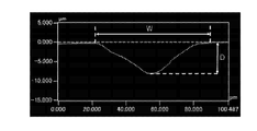
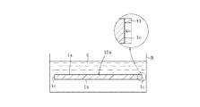
- “(depth D ( ⁇ m) of the recessed region) / (width W ( ⁇ m) of the recessed region)” is measured by the following method. First, the end face of the glass plate as shown in FIG. 1 is observed with a laser microscope.
- the depth is measured by scanning the laser in the thickness direction of the glass. This measurement was performed at 90 points, and the averaged profile is shown in FIG. From the profile shown in FIG. 2, the depth D ( ⁇ m) of the recessed region and the width W ( ⁇ m) of the recessed region are obtained, and (depth D ( ⁇ m) of the recessed region) / (width W of the recessed region). ( ⁇ m)) is calculated.
- the thickness of the glass plate is preferably 0.3 mm or less.
- the three-point bending strength of the glass plate is preferably 285 N / mm 2 or more.
- an optical film is formed on at least one main surface.
- the optical film is at least one of an antireflection film, a visible light shielding film, a near infrared ray shielding film, an ultraviolet ray shielding film, and an ultraviolet ray and a near infrared ray shielding film.
- the glass plate contains 10% or more of P 2 O 5 in mass% by mass.
- the glass plate has a thickness of 0.05 mm and a light transmittance of 80% or more at a wavelength of 400 nm.
- the glass plate has a thickness of 0.05 mm and a light transmittance of 50% or less at a wavelength of 800 nm.
- the glass plate is near infrared absorbing glass.
- the method for manufacturing a glass plate of the present invention includes a step of preparing a base material of a glass plate having a pair of front and back main surfaces, and a modified portion inside the base material by irradiating the base material with laser light.
- the modified portion is provided so as not to reach the pair of main surfaces, the glass plate is made of phosphate glass, and the etching solution is provided. However, it is an alkaline detergent, and the thickness of the end face of the glass plate removed by the etching solution is 1 ⁇ m or more.
- the etching solution contains an alkaline salt of a chelating agent as an alkaline component.
- a film forming step of forming an optical film on at least one main surface of the glass plate before the etching step it is preferable to include a film forming step of forming an optical film on at least one main surface of the glass plate before the etching step.
- FIG. 3 is a schematic perspective view showing the glass plate of the present invention.
- the glass plate 10 has a first main surface 1a and a second main surface 1b facing each other, and an end surface 1c connecting the first main surface 1a and the second main surface 1b.
- the main surface of the glass plate 10 is formed in a quadrangular shape, but the shape is not limited to this, and may be, for example, a triangle, a polygon of a pentagon or more, or a circle.
- the end face 1c is formed so that the main surface is substantially orthogonal to the main surface 1a on each side of the rectangular glass plate 1.
- the thickness of the glass plate 10 is preferably 0.3 mm or less. It is more preferably 0.19 mm or less, still more preferably 0.15 mm or less, and particularly preferably 0.12 mm or less. On the other hand, the thickness of the glass plate 10 is preferably 0.01 mm or more, 0.02 mm or more, 0.03 mm or more, 0.05 mm or more, and particularly preferably 0.08 mm or more.
- Area of the main surface 1a, 1b of the glass plate 10 can be a 1 mm 2 or more 25000 mm 2 or less.
- the main surface 1a, a preferred range of area 1b is, 3 mm 2 or more 25000 mm 2 or less, more preferably 9 mm 2 or more 25000 mm 2 or less, more preferably 15 mm 2 or more 25000 mm 2 or less, particularly preferably is 20 mm 2 or more 25000 mm 2 or less .
- the end face 1c is provided with a recessed region 2.
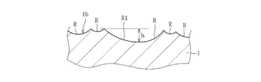
- a plurality of recesses R are formed in the recessed region 2 of the end surface 1c of the glass plate 10 as schematically shown in FIG.
- the outer circumference of the top of the recess R (the ridgeline of the recess R if it is adjacent) C has, for example, a substantially circular shape or a substantially elliptical shape.
- the first recess R1 in which the maximum value d of the linear distance between two points on the outer circumference C of the top is 0.5 ⁇ m or more.
- the ratio is 50% or more.
- the maximum value d of the linear distance between two points on the outer circumference C of the top is less than 0.5 ⁇ m.
- the ratio of the two recesses (not shown) is less than 50%.
- the maximum value d of the linear distance is a diameter when the concave portion R is circular, and a major diameter when the concave portion R is elliptical.
- the force is appropriately applied by the relatively large first recess R1 formed in the recess region 2 of the end surface 1c. It is thought that it can be dispersed. As a result, cracks starting from the end surface 1c of the glass plate 10 are less likely to develop, and damage to the glass plate 10 can be reduced.
- the relatively small second recess cannot be expected to have the above-mentioned effect of dispersing the external force so much, and may cause damage on the contrary. Therefore, it is preferable to increase the proportion of the first recess R1 and decrease the proportion of the second recess.
- the ratio of the first recess R1 is preferably 85% or more, and more preferably 90% or more.
- the total number of recesses R included in the arbitrary 30 ⁇ m ⁇ range S of the recessed region 2 of the end face 1c, that is, the total of the first recess R1 and the second recess is preferably 1 or more and 300 or less. As the total number of recesses R decreases, the number of second recesses tends to decrease and the first recess R1 tends to become more dominant. Therefore, in consideration of this point, the total number of recesses R is preferably 300 or less, and more preferably 150 or less. On the other hand, if the total number of recesses R is reduced more than necessary, the processing time in the etching process described later becomes long, and the production efficiency deteriorates.
- the total number of recesses R is preferably 1 or more, and more preferably 3 or more.
- the depth h of the first recess R1 is preferably 0.5 ⁇ m or more, and more preferably 1 ⁇ m or more.
- the depth h is the height difference between the deepest position of the first recess R1 and the highest position on the outer circumference C of the top of the first recess R1. By doing so, it is considered that the first recess R1 becomes sufficiently deep and the effect of dispersing the external force is more exerted.
- the depth h of the first recess R1 is preferably 10 ⁇ m or less, and more preferably 5 ⁇ m or less.
- the recessed region 2 is provided on the end surface 1c and does not reach the first main surface 1a and the second main surface 1b.
- the center of the end face 1c in the thickness direction and the center of the recessed region 2 in the thickness direction are at the same position. Thereby, the glass 10 can be more reliably made hard to break.
- the center of the end face 1c in the thickness direction and the center of the recessed region 2 in the thickness direction may be different from each other.
- (Depth D ( ⁇ m) of the recessed region) / (Width W ( ⁇ m) of the recessed region) is preferably 0.03 or more, 0.035 or more, 0.04 or more, and 0. It is .045 or more, 0.05 or more, 0.055 or more, 0.06 or more, 0.065 or more, and more preferably 0.07 or more. By doing so, it is considered that the concave portion becomes sufficiently deep and the effect of dispersing the external force is more exerted. Further, when packaging with peripheral parts using an adhesive, it is considered that the adhesive force is increased by the anchor effect and peeling is less likely to occur.
- the upper limit of (depth D ( ⁇ m) of the recessed region) / (width W ( ⁇ m) of the recessed region) is not particularly limited, but is actually 1 or less.
- 3-point bending strength of the glass plate 10 is preferably 285N / mm 2 or more and 290 N / mm 2 or more and 295N / mm 2 or more and 300N / mm 2 or more, at 310N / mm 2 or more There is a 315N / mm 2 or more and 320N / mm 2 or more, more preferably 325N / mm 2 or more.
- the upper limit of the three-point bending strength of the glass plate 10 is not particularly limited, but is about 450 N / mm 2 due to the nature of the material.
- the glass plate 10 is a phosphate-based glass having an excellent near-infrared absorbing function.
- the phosphate-based glass used for the glass plate 10 does not substantially contain F (fluorine).
- substantially free means that the fluorine content is 0.1% or less in mass%.
- Examples of such phosphate type glasses such as P 2 O 5 can be used which contain more than 10 wt%. Specifically, in terms of mass%, P 2 O 5 10 to 70%, Al 2 O 30 to 19%, RO (where R is at least one selected from Mg, Ca, Sr and Ba) 0 to 50. %, ZnO 0 to 13%, K 2 O 0 to 50%, Na 2 O 0 to 50%, Li 2 O 0 to 50%, and CuO 1 to 40%, and substantially free of fluorine. Glass can be used.
- P 2 O 5 is a component that forms a glass skeleton.
- the content of P 2 O 5 is 10 to 70%, 15 to 65%, 16 to 64%, 17 to 63%, 18 to 62%, 19 to 61%, 20 to 60%, 25 to% by mass. It is preferably 58%, 31-56%, 41-55%, 45-54%, particularly 47-53%. If the content of P 2 O 5 is too small, vitrification may become unstable. On the other hand, if the content of P 2 O 5 is too large, the weather resistance may be easily lowered.
- Al 2 O 3 is a component that further improves weather resistance.
- the content of A1 2 O 3 is preferably 0 to 19%, 1 to 14%, 2 to 10%, 3 to 8%, and particularly 4 to 6% in mass%. If the content of Al 2 O 3 is too low, the weather resistance may not be sufficient. On the other hand, if the content of Al 2 O 3 is too large, the meltability may decrease and the melting temperature may rise. When the melting temperature rises, Cu ions are reduced and it becomes easy to shift from Cu 2+ to Cu + , so that it may be difficult to obtain desired optical characteristics. Specifically, the light transmittance in the near-ultraviolet to visible region may decrease, or the near-infrared absorption characteristic may easily decrease.
- RO (however, R is at least one selected from Mg, Ca, Sr and Ba) is a component that improves weather resistance and meltability.
- the content of RO is 0 to 50%, 3 to 30%, 3.3 to 29%, 3.4 to 28%, 3.5 to 27%, 3.6 to 26%, and 3. It is preferably 7 to 25%, 3.8 to 24%, 3.9 to 23%, 4 to 22%, and particularly preferably 5 to 20%. If the RO content is too low, the weather resistance and meltability may not be sufficient. On the other hand, if the content of RO is too large, the stability of the glass tends to decrease, and crystals due to the RO component may easily precipitate.
- the preferable range of the content of each component of RO is as follows.
- MgO is a component that improves weather resistance.
- the content of MgO is 0 to 15%, 0.2 to 7%, 0.3 to 5%, 0.4 to 3.7%, 0.5 to 3.6%, 0.6 in mass%. ⁇ 3.5%, 0.7 ⁇ 3.4%, 0.8 ⁇ 3.3%, 0.9 ⁇ 3.2%, 0.8 ⁇ 3.1%, especially 0.9 ⁇ 3% It is preferable to have. If the MgO content is too high, the stability of the glass may easily decrease.
- CaO is a component that improves weather resistance like MgO.
- the CaO content is preferably 0 to 15%, 0.4 to 10%, and particularly preferably 1 to 7% in terms of mass%. If the CaO content is too high, the stability of the glass may easily decrease.
- SrO is a component that improves weather resistance like MgO.
- the content of SrO is preferably 0 to 12%, 0.3 to 10%, and particularly preferably 0.5 to 5% in terms of mass%. If the content of SrO is too high, the stability of the glass may easily decrease.
- BaO is a component that stabilizes glass and improves weather resistance.
- the content of BaO is preferably 0 to 30%, 5 to 30%, 7 to 25%, 10 to 23%, and particularly preferably 15 to 20% in terms of mass%. If the content of BaO is too small, the glass may not be sufficiently stabilized or the weather resistance may not be sufficiently improved. On the other hand, if the content of BaO is too large, crystals derived from BaO may easily precipitate during molding.
- ZnO is a component that improves the stability and weather resistance of glass.
- the content of ZnO is mass%, preferably 0 to 13%, more preferably 0 to 12%, and even more preferably 0 to 10%. If the content of ZnO is too large, the meltability is lowered and the melting temperature is raised, and as a result, it may be difficult to obtain desired optical characteristics. In addition, the stability of the glass may decrease, and crystals due to the ZnO component may easily precipitate.
- RO and ZnO have an effect of improving the stabilization of glass, and it is easy to enjoy the effect especially when P 2 O 5 is small.
- the ratio of the content of P 2 O 5 with respect to RO is preferably 1.0 to 1.9, and more preferably 1.2 to 1.8. If the ratio (P 2 O 5 / RO) is too small, the liquidus temperature may rise and devitrification due to RO may easily precipitate. On the other hand, if P 2 O 5 / RO is too large, the weather resistance may easily decrease.
- K 2 O is a component that lowers the melting temperature.
- the K 2 O content in mass%, 0-50%, greater than 0 to 40% 3-30% 3.3 - 28% 4-25% 5-20% 6 to 19% It is preferably 6.2 to 18.5%, 10 to 18%, and particularly preferably 14 to 17%. If the content of K 2 O is too small, the melting temperature may become high and it may be difficult to obtain desired optical characteristics. On the other hand, if the content of K 2 O is too large, crystals derived from K 2 O are likely to precipitate during molding, and vitrification may become unstable.
- Na 2 O is also a component that lowers the melting temperature.
- the content of Na 2 O is preferably 0 to 50%, more than 0 to 40%, 0.5 to 30%, 0.8 to 20%, and particularly preferably 1 to 10% in terms of mass%. If the Na 2 O content is too high, vitrification may become unstable.
- Li 2 O is also, along with a component that lowers the same melting temperature and K 2 O, Li 2 O is a component to increase the light transmittance of the ultraviolet to visible region.
- the content of Li 2 O is 0 to 50%, more than 0 to 40%, 0.2 to 30%, 0.3 to 20%, 0.4 to 6%, 0.5 to 5%, 0.6 to 4%, 0.65 to 3%, 0.66 to 2%, 0.67 to 1.5%, 0.68 to 1.2%, 0.69 to 1.0%, especially 0.7 to 0 It is preferably 9.9%. If the content of Li 2 O is too large, the liquidus temperature rises and the devitrification resistance tends to decrease.
- CuO is a component for absorbing near infrared rays.
- the content of CuO is 1 to 40% by mass, preferably 2 to 35%, 3 to 30%, 4 to 25%, 5 to 20%, and particularly preferably 6 to 15%. If the CuO content is too low, the desired near-infrared absorption characteristics may not be obtained. On the other hand, if the content of CuO is too large, the light transmittance in the ultraviolet to visible region may be easily lowered. In addition, vitrification may become unstable.
- the CuO content for obtaining desired optical characteristics is preferably adjusted appropriately depending on the plate thickness.
- B 2 O 3 , Nb 2 O 5 , Y 2 O 3 , La 2 O 3 , Ta 2 O 5 , CeO 2 or Sb 2 O 3 and the like are within the range that does not impair the effects of the present invention. It may be contained in. Specifically, the content of each of these components is mass%, preferably 0 to 3%, and more preferably 0 to 2%.
- SiO 2 is a component that strengthens the glass skeleton. It also has the effect of improving weather resistance.
- the content of SiO 2 is 0 to 10%, 0.1 to 8%, 0.6 to 7.5%, 0.7 to 7%, 0.8 to 6.5%, 0.85 to 6.4. %, 0.9 to 6.2%, particularly preferably 1 to 6%. If the content of SiO 2 is too large, the weather resistance tends to decrease. In addition, vitrification tends to be unstable.
- the glass plate 10 having the above composition By using the glass plate 10 having the above composition, it is possible to achieve both a higher light transmittance in the visible region and an even better light absorption characteristic in the near infrared region.
- the light transmittance at a thickness of 0.05 mm and a wavelength of 400 nm is 80% or more, 81% or more, 82% or more, 83% or more, 84% or more, 85% or more, 86% or more, especially 87%.
- the light transmittance at a wavelength of 800 nm is 50% or less, 40% or less, 35% or less, 30% or less, 29% or less, 28% or less, 27% or less, 26% or less, and particularly 25% or less.
- the light transmittance at a wavelength of 1200 nm is 70% or less, 65% or less, 60% or less, 59% or less, 58% or less, 57% or less, 56% or less, 55% or less, 54% or less, 53% or less, particularly. It is preferably 52% or less.
- the visible region means a wavelength of 380 to 700 nm
- the near infrared region means a wavelength of 700 to 1200 nm.
- an optical film may be formed on the main surface 1a and / or the main surface 1b of the glass plate 10.
- the optical film is appropriately selected depending on the application, and is, for example, an antireflection film (AR film), a visible light shielding film, a near infrared ray shielding film (IR cut film), an ultraviolet ray shielding film, an ultraviolet ray and a near infrared ray shielding film.
- Functional membranes such as membranes can be mentioned.
- the optical film may have the functions of both an antireflection film and a near-infrared shielding film.
- a dielectric multilayer film formed by alternately laminating low refractive index layers and high refractive index layers can be used.
- a silicon oxide film or the like is used.
- a metal oxide film composed of at least one selected from tantalum oxide, niobium oxide, titanium oxide, hafnium oxide, silicon nitride, and zirconium oxide is used.
- the optical film formed on one main surface 1a of the glass plate 10 and the optical film formed on the other main surface 1b of the glass plate 1 may have the same function or different functions. It may be a film having.
- the configuration of the glass plate with an optical film is, for example, antireflection film / glass plate / antireflection film, antireflection film / glass plate / near infrared ray shielding film, near infrared ray shielding film / glass plate / near infrared ray shielding film. Films, near-infrared shielding films / glass plates / ultraviolet rays and near-infrared shielding films.
- FIGS. 6 (a) and 6 (b) are schematic cross-sectional views for explaining an example of the method for manufacturing a glass plate of the present invention.
- 7 (a) and 7 (b) are schematic cross-sectional views for explaining an example of the method for manufacturing a glass plate of the present invention.
- the directions z in FIGS. 6 (a) and 6 (b) and 7 (a) and 7 (b) indicate the thickness direction.
- the direction x and the direction y indicate the respective directions in the plane direction.
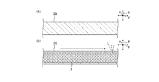
- 6 (a) and 6 (b) are cross-sectional views seen from the x direction
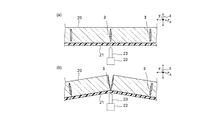
- FIGS. 7 (a) and 7 (b) are cross-sectional views seen from the y direction perpendicular to the x direction.
- a glass base material 20 is prepared.
- the glass base material 20 can be formed into a plate shape by, for example, a casting method, a rollout method, a downdraw method, a redraw method, a float method, an overflow method, or the like. Further, it is preferable to use a glass base material 20 having the above-mentioned composition and characteristics.
- the laser beam L is scanned and irradiated along the portion where the base material 20 is divided. The laser beam L is irradiated so that the focal position is inside the base material 20.
- the modified portion 3 is provided inside the base material 20.
- one modification unit 3 is provided in the thickness direction z.
- the modification unit 3 may be provided by scanning the laser beam L a plurality of times, or may be provided by scanning the laser beam L once.
- the reforming portion 3 extending in the y direction is shown, but the modifying portion 3 extending in the x direction is also provided in the same manner. Further, a plurality of modification units 3 may be provided in the y direction and the x direction, respectively.
- a support 21 used for cutting the base material 20 is prepared.
- the configuration of the support 21 is not particularly limited, but the support 21 has a resin film and an adhesive layer provided on the resin film.
- the base material 20 is attached to the pressure-sensitive adhesive layer of the support 21.
- the pressing member 22 is arranged on the support 21 side so as to overlap the region of the base material 20 where the modified portion 3 is provided in a plan view.
- the pressing member 22 is a member for cutting the base material 20, and has a blade 23 extending linearly in the y direction.
- the base material 20 is pressed from the support 21 side by moving the pressing member 22 toward the base material 20 side.
- the region of the base material 20 where the modified portion 3 is provided is indirectly pressed by the blade 23 via the support 21.
- the base metal 20 is cut along the modified portion 3 in the thickness direction z. In this way, the base metal 20 is cut along the modified portion 3 to obtain the glass plate 10a.
- the base metal 20 is divided as described above, cracks extending in the x direction or the y direction are unlikely to occur. Therefore, the glass plate 10a is less likely to be damaged.
- the reformed portion 3 is modified so as not to reach the main surface and at the center of the cross section (end face of the glass plate after cutting) of the base metal 20 in the thickness direction z and in the thickness direction z. It is more preferable to provide the reforming section 3 so that the center of the quality section 3 is at the same position. Thereby, the distance between both main surfaces of the base material 20 and the modified portion 3 can be more reliably increased. As a result, cracks are less likely to propagate to the main surface, and damage to the glass plate 10 can be made less likely to occur.
- the ratio of the modified portion 3 to the cross section in the thickness direction z is 10 to 90%, 20 to 80%, 30 to 70%, 35 to 65%, 40 to 60%. In particular, it may be set to 45 to 55%.
- the glass plate 10 of the present invention is obtained by etching the end face 1c of the obtained glass plate 10a with the etching solution E contained in the etching tank D.
- An alkaline detergent is used as the etching solution E.
- a detergent containing an alkaline component such as Na or K, a surfactant such as triethanolamine, benzyl alcohol or glycol, or water or alcohol can be used.
- the alkaline component contained in the alkaline detergent contains an alkaline salt of a chelating agent such as aminopolycarboxylic acid.
- a chelating agent such as aminopolycarboxylic acid.
- the alkaline salt of the aminopolycarboxylic acid include sodium salts and potassium salts such as diethylenetriaminepentacetic acid, ethylenediaminetetraacetic acid, triethylenetetraaminehexacetic acid and nitrilotriacetic acid.
- diethylenetriamine pentaacetate pentasodium diethylenetriamine pentaacetate pentasodium, ethylenediaminetetraacetate tetrasodium, triethylenetetraamine hexaacetic acid hexasodium, and nitrilotriacetate trisodium are preferably used, and diethylenetriamine pentaacetate pentasodium is particularly preferably used.
- the etching step conditions such as etching time are adjusted so that the thickness t1 removed in the plane direction by etching the end face 1c of the glass plate 10a is 1 ⁇ m or more.
- the end face 1c of the glass plate 10a is sufficiently etched by the etching solution E made of an alkaline detergent, and the ratio of the first recess R1 in the recess region 2 of the end face 1c after etching tends to exceed 50%.
- the removal thickness t1 is preferably 5 ⁇ m or more, more preferably 7 ⁇ m or more, and particularly preferably 10 ⁇ m or more.
- An optical film may be formed on the main surface 1a and / or the main surface 1b of the glass plate 10a before etching.
- the film forming method include a vacuum vapor deposition method, an ion plating method, and a sputtering method.
- Example 2 A glass plate having a thickness of 0.10 mm made of phosphate-based glass containing 10% by mass or more of P 2 O 5 was prepared, and a modified portion was provided inside the glass plate by irradiating with laser light. Next, the glass plate was cut along the area where the modified portion was provided. Then, the cut glass plate was immersed in an alkaline detergent (etching solution) containing an alkaline salt of a chelating agent and etched. The etching time was set within a range in which the thickness removed by etching the end face of the glass plate was 1 ⁇ m or more. As a result, a glass plate having a concave region having a main surface having a size of 6 mm ⁇ 6 mm and a thickness of 0.10 mm was obtained.
- etching solution alkaline detergent
- the 3-point bending strength means that a glass plate with a thickness of 6 mm ⁇ and a plate thickness of 0.1 mm is placed on two fulcrums arranged at a distance of 2.5 mm, and a crosshead speed of 0.5 mm / min is applied to one central point between the fulcrums.
- the bending strength was as high as 329 MPa because there were recesses and the recessed region did not reach the main surface.
- the bending strength was as low as 224 MPa because there were no recesses.
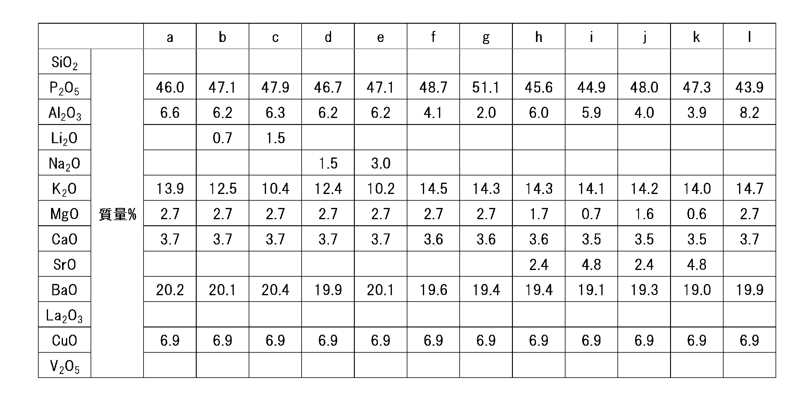
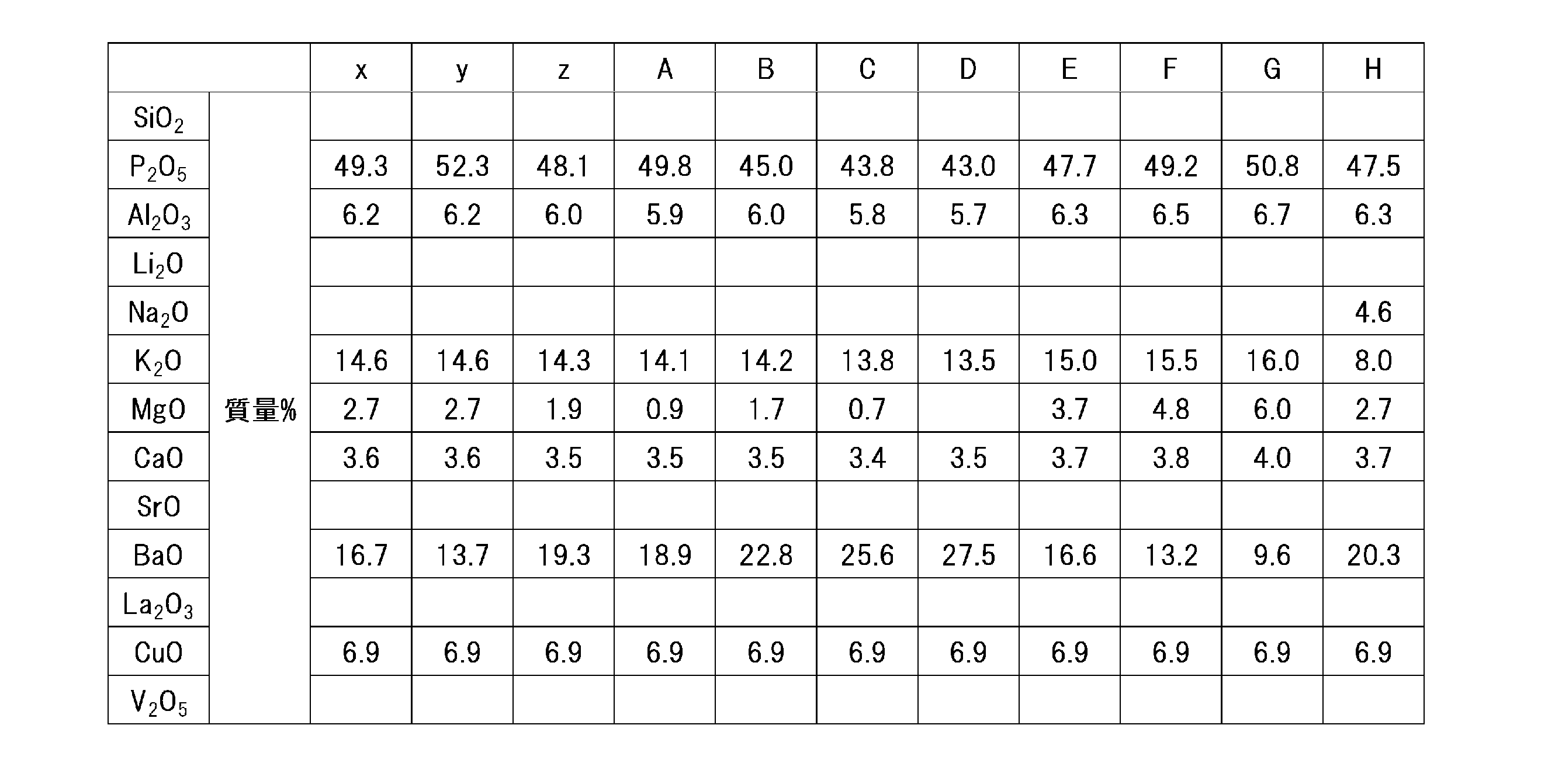
- Tables 2 to 5 show examples of glass composition of the glass plate of the present invention.
Landscapes
- Chemical & Material Sciences (AREA)
- Engineering & Computer Science (AREA)
- Materials Engineering (AREA)
- Organic Chemistry (AREA)
- Chemical Kinetics & Catalysis (AREA)
- General Chemical & Material Sciences (AREA)
- Geochemistry & Mineralogy (AREA)
- Life Sciences & Earth Sciences (AREA)
- Physics & Mathematics (AREA)
- Optics & Photonics (AREA)
- Thermal Sciences (AREA)
- Oil, Petroleum & Natural Gas (AREA)
- Plasma & Fusion (AREA)
- Mechanical Engineering (AREA)
- Glass Compositions (AREA)
Abstract
ガラス板の端面強度の向上を図り、ガラス板の破損を低減する。 表裏一対の主表面と、前記一対の主表面各々の端部を結ぶ端面とを備えたガラス板において、 前記端面は、複数の凹部からなる凹部領域を有し、 前記凹部領域の任意の30μm□の範囲内に含まれる前記凹部のうち、頂部外周上の二地点間の直線距離の最大値が0.5μm以上となる第一凹部の割合が50%以上であり、 前記凹部領域が前記主表面に至っていないことを特徴とするガラス板。
Description
本発明は、ガラス板及びその製造方法に関する。
デジタルスチルカメラやビデオカメラに利用されるCCDやCMOSなどの固体撮像素子の分光感度は、近赤外域の光に対して強い感度を有する。これらの固体撮像素子の分光感度を人間の視感度特性に合わせるために視感度補正部材が用いられるのが一般的である。
視感度補正部材としては、例えば、特許文献1に開示されているように、ガラス板の主表面に赤外線遮蔽機能を有する光学膜が形成されたガラス板が利用される。また、ガラス板表面の反射を防止するために、反射防止機能を有する光学膜が形成される場合もある。
ところで、固体撮像素子などに利用されるガラス板は薄板化が進められている。これに伴って、ガラス板が搬送時の衝撃などによって容易に破損するという問題がある。特に、このようなガラス板の破損は、ガラス板の端面を起点とするクラックの進展により生じることが多く、端面強度の更なる向上が望まれている。
本発明は、ガラス板の端面強度の向上を図り、ガラス板の破損を低減することを課題とする。
本発明のガラス板は、表裏一対の主表面と、前記一対の主表面各々の端部を結ぶ端面とを備えたガラス板において、前記端面は、複数の凹部からなる凹部領域を有し、前記凹部領域の任意の30μm□の範囲内に含まれる前記凹部のうち、頂部外周上の二地点間の直線距離の最大値が0.5μm以上となる第一凹部の割合が50%以上であり、前記凹部領域が前記主表面に至っていないことを特徴とする。このような構成によれば、端面の凹部領域において、前記凹部領域の任意の30μm□の範囲内に含まれる前記凹部のうち、頂部外周上の二地点間の直線距離の最大値が0.5μm以上となる相対的に大きな第一凹部が過半数を占める。従って、ガラス板の端面に衝撃などの外力が作用した場合であっても、その力を形成された相対的に大きな第一凹部によって分散できると考えられる。その結果、ガラス板の端面を起点とするクラックが進展し難くなり、ガラス板の破損を低減することができる。なお、凹部はガラスの端面の改質部に存在するクラックにエッチング液が浸透することにより形成される。また、「凹部領域」は多数の凹部が存在する領域であり、「改質部」はレーザー光の照射等により、ガラスの屈折率や透過率等に変化が生じた部分である。
上記の構成において、端面凹部領域の任意の30μm□の範囲内に含まれる凹部の総数が、1個以上300個以下であることが好ましい。
上記の構成において、第一凹部の深さが0.5μm以上であることが好ましい。
上記の構成において、厚み方向における端面の中心と、厚み方向における凹部領域の中心とが同じ位置であることが好ましい。
上記の構成において、(前記凹部領域の深さD(μm))/(前記凹部領域の幅W(μm))が0.03以上であることが好ましい。なお、(前記凹部領域の深さD(μm))/(前記凹部領域の幅W(μm))とは、前記凹部領域の深さD(μm)を前記凹部領域の幅W(μm)で除した値である。ここで、「(前記凹部領域の深さD(μm))/(前記凹部領域の幅W(μm))」は、以下の方法で測定する。まず、図1に示すようなガラス板の端面をレーザー顕微鏡にて観察する。次に、ガラスの板厚方向にレーザーを走査し深さ測定を行う。この測定を90箇所行い、平均化したプロファイルを図2に示す。図2に示すプロファイルから、前記凹部領域の深さD(μm)、前記凹部領域の幅W(μm)を求め、(前記凹部領域の深さD(μm))/(前記凹部領域の幅W(μm))を算出する。
上記の構成において、ガラス板の厚みが0.3mm以下であることが好ましい。
上記の構成において、ガラス板の3点曲げ強度が285N/mm2以上であることが好ましい。
上記の構成において、少なくとも一方の主表面に光学膜が形成されていることが好ましい。
この場合、光学膜が、反射防止膜、可視光遮蔽膜、近赤外線遮蔽膜、紫外線遮蔽膜、紫外線及び近赤外線遮蔽膜の少なくとも1種であることが好ましい。
上記の構成において、ガラス板が、組成として質量%でP2O5を10%以上含むことが好ましい。
上記の構成において、ガラス板が、厚み0.05mm換算、波長400nmにおける光透過率が80%以上であることが好ましい。
上記の構成において、ガラス板が、厚み0.05mm換算、波長800nmにおける光透過率が50%以下であることが好ましい。
上記の構成において、ガラス板が近赤外線吸収ガラスであることが好ましい。
本発明のガラス板の製造方法は、表裏一対の主表面を備えたガラス板の母材を用意する工程と、前記母材にレーザー光を照射することにより、前記母材の内部に改質部を設ける工程と、前記改質部が設けられている部分に沿い前記母材を割断してガラス板を得る工程と、前記母材の割断により生じた前記ガラス板の端面をエッチング液に接触させてエッチングするエッチング工程を備え、前記改質部を設ける工程において、前記改質部が前記一対の主表面に至らないように設け、前記ガラス板が、リン酸塩系ガラスからなり、前記エッチング液が、アルカリ洗剤であり、前記ガラス板の前記端面の前記エッチング液による除去厚みが、1μm以上であることを特徴とする。
上記の構成において、エッチング液が、アルカリ成分としてキレート剤のアルカリ塩を含むことが好ましい。
上記の構成において、エッチング工程の前に、ガラス板の少なくとも一方の主表面に光学膜を形成する成膜工程を備えていることが好ましい。
以上のような本発明によれば、ガラス板の端面強度の向上を図り、ガラス板の破損を低減することができる。
本発明のガラス板及びその製造方法について、図面を参照しながら説明する。
図3は、本発明のガラス板を示す模式的斜視図である。図3に示すように、ガラス板10は、対向し合う第1の主表面1a及び第2の主表面1bと、第1の主表面1a及び第2の主表面1bを接続する端面1cとを有する。ガラス板10の主表面は、四角形状に形成されるが、この形状に限定されず、例えば三角形や五角形以上の多角形や円形などであってもよい。本実施形態では、端面1cは、主表面が四角形状のガラス板1の各辺において、主表面1aとほぼ直交するように形成されている。
ガラス板10の厚みは、0.3mm以下であることが好ましい。より好ましくは0.19mm以下であり、さらに好ましくは、0.15mm以下、特に好ましくは0.12mm以下である。一方、ガラス板10の厚みは、0.01mm以上、0.02mm以上、0.03mm以上、0.05mm以上、特に0.08mm以上であることが好ましい。
ガラス板10における主表面1a、1bの面積は、1mm2以上25000mm2以下とすることができる。主表面1a、1bの面積の好ましい範囲は、3mm2以上25000mm2以下、より好ましくは9mm2以上25000mm2以下、さらに好ましくは15mm2以上25000mm2以下、特に好ましくは20mm2以上25000mm2以下である。
端面1cには、凹部領域2が設けられている。ガラス板10の端面1cの凹部領域2には、図4に模式的に示すように、凹部Rが複数形成されている。凹部Rの頂部外周(凹部Rが隣接する場合はその稜線)Cは、例えば略円形又は略楕円形を呈する。
端面1cの凹部領域2の任意の30μm□の範囲S内に含まれる凹部Rのうち、頂部外周C上の二地点間の直線距離の最大値dが0.5μm以上となる第一凹部R1の割合は50%以上である。換言すれば、端面1cの凹部領域2の任意の30μm□の範囲S内に含まれる凹部Rのうち、頂部外周C上の二地点間の直線距離の最大値dが0.5μm未満となる第二凹部(不図示)の割合は50%未満である。ここで、直線距離の最大値dは、凹部Rが円形の場合は直径、楕円形の場合は長径となる。このようにすれば、ガラス板10の端面1cに衝撃などの外力が作用した場合であっても、その力を端面1cの凹部領域2に形成された相対的に大きな第一凹部R1によって適度に分散できると考えられる。その結果、ガラス板10の端面1cを起点とするクラックが進展し難くなり、ガラス板10の破損を低減することができる。なお、相対的に小さな第二凹部は、上記の外力の分散効果はあまり期待できず、逆に破損の原因になるおそれがある。従って、第一凹部R1の割合を多くし、第二凹部の割合を少なくすることが好ましい。第一凹部R1の割合は85%以上であることが好ましく、90%以上であることがより好ましい。
端面1cの凹部領域2の任意の30μm□の範囲S内に含まれる凹部Rの総数、すなわち、第一凹部R1と第二凹部の合計は、1個以上300個以下であることが好ましい。凹部Rの総数が少なくなるに連れ、第二凹部の数は少なくなり、第一凹部R1がより支配的になる傾向がある。従って、この点を勘案すると、凹部Rの総数は300個以下であることが好ましく、150個以下であることがより好ましい。一方、凹部Rの総数を必要以上に少なくしようとすると、後述するエッチング工程における処理時間が長くなり、生産効率が悪くなる。また、凹部Rの総数がある程度少なくなると、凹部Rの総数を更に少なくしてもガラス板1の破損率が変化しなくなる場合がある。従って、これらの点を勘案すると、凹部Rの総数は1個以上であることが好ましく、3個以上であることがより好ましい。
図5に示すように、第一凹部R1の深さhは、0.5μm以上であることが好ましく、1μm以上であることがより好ましい。ここで、深さhは、第一凹部R1の最も深い位置と、第一凹部R1の頂部外周C上の最も高い位置との高低差である。このようにすれば、第一凹部R1が十分深くなり、外力の分散効果がより発揮されると考えられる。なお、第一凹部R1の深さhは、10μm以下であることが好ましく、5μm以下であることがより好ましい。
本実施形態においては、凹部領域2は、端面1cに設けられており、第1の主表面1a及び第2の主表面1bには至っていない。これにより、凹部領域2が設けられた部分に沿って母材を割断してガラス10を得る際に、凹部領域2を起点としてクラックが発生しても、発生したクラックが第1の端縁部1d及び第2の端縁部1eまで進展し難くなり、端面強度が向上しやすくなる。
厚み方向における端面1cの中心と、厚み方向における凹部領域2の中心とが同じ位置であることが好ましい。それによって、ガラス10をより確実に破損し難くすることができる。なお、厚み方向における端面1cの中心と、厚み方向における凹部領域2の中心とは異なる位置であっても構わない。
(前記凹部領域の深さD(μm))/(前記凹部領域の幅W(μm))は、好ましくは0.03以上であり、0.035以上であり、0.04以上であり、0.045以上であり、0.05以上であり、0.055以上であり、0.06以上であり、0.065以上であり、より好ましくは0.07以上である。このようにすれば、凹部が充分深くなり、外力の分散効果がより発揮されると考えられる。また、接着剤を使用した周辺部品とのパッケージングの際に、アンカー効果により接着力が高まり剥離が起こりにくくなる効果が考えられる。なお、(前記凹部領域の深さD(μm))/(前記凹部領域の幅W(μm))の上限は特に限定されないが現実的には1以下である。
ガラス板10の3点曲げ強度は、好ましくは285N/mm2以上であり、290N/mm2以上であり、295N/mm2以上であり、300N/mm2以上であり、310N/mm2以上であり、315N/mm2以上であり、320N/mm2以上であり、より好ましくは325N/mm2以上である。3点曲げ強度が上記下限以上である場合、ガラス板10の割れをより一層生じ難くすることができる。なお、ガラス板10の3点曲げ強度の上限は、特に制限されないが、材料の性質上450N/mm2程度である。
以下に、ガラス板10が、近赤外線吸収機能に優れるリン酸塩系ガラスである場合の例を示す。
ガラス板10に用いられるリン酸塩系ガラスは、F(フッ素)を実質的に含んでいないことが望ましい。ここで、「実質的に含んでいない」とは、フッ素の含有量が質量%で0.1%以下であることを意味している。
このようなリン酸塩系ガラスとしては、例えばP2O5を10質量%以上含有するものを用いることができる。具体的には、質量%で、P2O5 10~70%、Al2O3 0~19%、RO(ただしRは、Mg、Ca、Sr及びBaから選択される少なくとも一種) 0~50%、ZnO 0~13%、K2O 0~50%、Na2O 0~50%、Li2O 0~50%及びCuO 1~40%を含有し、フッ素を実質的に含んでいない、ガラスを用いることができる。
P2O5は、ガラス骨格を形成する成分である。P2O5の含有量は、質量%で、10~70%、15~65%、16~64%、17~63%、18~62%、19~61%、20~60%、25~58%、31~56%、41~55%、45~54%、特に47~53%であることが好ましい。P2O5の含有量が少なすぎると、ガラス化が不安定になる場合がある。一方、P2O5の含有量が多すぎると、耐候性が低下し易くなることがある。
Al2O3は、耐候性をより一層向上させる成分である。A12O3の含有量は、質量%で、0~19%、1~14%、2~10%、3~8%、特に4~6%であることが好ましい。Al2O3の含有量が少なすぎると、耐候性が十分でないことがある。一方、Al2O3の含有量が多すぎると、溶融性が低下して溶融温度が上昇する場合がある。なお、溶融温度が上昇すると、Cuイオンが還元されてCu2+からCu+にシフトし易くなるため、所望の光学特性が得られ難くなる場合がある。具体的には、近紫外~可視域における光透過率が低下したり、近赤外線吸収特性が低下し易くなったりすることがある。
RO(ただしRは、Mg、Ca、Sr及びBaから選択される少なくとも一種)は、耐候性を改善するとともに、溶融性を向上させる成分である。ROの含有量は、質量%で、0~50%、3~30%、3.3~29%、3.4~28%、3.5~27%、3.6~26%、3.7~25%、3.8~24%、3.9~23%、4~22%、特に5~20%であることが好ましい。ROの含有量が少なすぎると、耐候性及び溶融性が十分でない場合がある。一方、ROの含有量が多すぎると、ガラスの安定性が低下し易く、RO成分起因の結晶が析出し易くなることがある。
なお、ROの各成分の含有量の好ましい範囲は以下の通りである。
MgOは、耐候性を改善させる成分である。MgOの含有量は、質量%で、0~15%、0.2~7%、0.3~5%、0.4~3.7%、0.5~3.6%、0.6~3.5%、0.7~3.4%、0.8~3.3%、0.9~3.2%、0.8~3.1%、特に0.9~3%であることが好ましい。MgOの含有量が多すぎると、ガラスの安定性が低下し易くなることがある。
CaOは、MgOと同様に耐候性を改善させる成分である。CaOの含有量は、質量%で、0~15%、0.4~10%、特に1~7%であることが好ましい。CaOの含有量が多すぎると、ガラスの安定性が低下し易くなることがある。
SrOは、MgOと同様に耐候性を改善させる成分である。SrOの含有量は、質量%で、0~12%、0.3~10%、特に0.5~5%であることが好ましい。SrOの含有量が多すぎると、ガラスの安定性が低下し易くなることがある。
BaOは、ガラスを安定化するとともに、耐候性を向上させる成分である。BaOの含有量は、質量%で、0~30%、5~30%、7~25%、10~23%、特に15~20%であることが好ましい。BaOの含有量が少なすぎると、十分にガラスを安定化できなかったり、十分に耐候性を向上できなかったりする場合がある。一方、BaOの含有量が多すぎると、成形中にBaO起因の結晶が析出し易くなることがある。
ZnOは、ガラスの安定性及び耐候性を改善させる成分である。ZnOの含有量は、質量%で、好ましくは0~13%であり、より好ましくは0~12%であり、さらに好ましくは0~10%である。ZnOの含有量が多すぎると、溶融性が低下して溶融温度が高くなり、結果として所望の光学特性が得られ難くなる場合がある。また、ガラスの安定性が低下し、ZnO成分起因の結晶が析出し易くなる場合がある。
以上のように、RO及びZnOはガラスの安定化を改善する効果があり、特にP2O5が少ない場合に、その効果を享受し易い。
なお、ROに対するP2O5の含有量の比(P2O5/RO)は、好ましくは1.0~1.9であり、より好ましくは、1.2~1.8である。比(P2O5/RO)が小さすぎると、液相温度が高くなってRO起因の失透が析出し易くなる場合がある。一方、P2O5/ROが大きすぎると、耐候性が低下し易くなる場合がある。
K2Oは、溶融温度を低下させる成分である。K2Oの含有量は、質量%で、0~50%、0超~40%、3~30%、3.3~28%、4~25%、5~20%、6~19%、6.2~18.5%、10~18%、特に14~17%であることが好ましい。K2Oの含有量が少なすぎると、溶融温度が高くなって所望の光学特性が得られ難くなることがある。一方、K2Oの含有量が多すぎると、K2O起因の結晶が成形中に析出し易くなり、ガラス化が不安定になることがある。
Na2Oも、K2Oと同様に溶融温度を低下させる成分である。Na2Oの含有量は、質量%で、0~50%、0超~40%、0.5~30%、0.8~20%、特に1~10%であることが好ましい。Na2Oの含有量が多すぎると、ガラス化が不安定になることがある。
Li2Oも、K2Oと同様に溶融温度を低下させる成分であるとともに、Li2Oは紫外~可視域の光透過率を上昇させる成分である。Li2Oを含有することにより、紫外~可視域の光透過率を低下させている酸素と銅イオンの間での電荷移動遷移による吸収を減少させることができる。Li2Oの含有量は0~50%、0超~40%、0.2~30%、0.3~20%、0.4~6%、0.5~5%、0.6~4%、0.65~3%、0.66~2%、0.67~1.5%、0.68~1.2%、0.69~1.0%、特に0.7~0.9%であることが好ましい。Li2Oの含有量が多すぎると液相温度が高くなり、耐失透性が低下しやすくなる。
CuOは、近赤外線を吸収するための成分である。CuOの含有量は、質量%で、1~40%であり、2~35%、3~30%、4~25%、5~20%、特に6~15%であることが好ましい。CuOの含有量が少なすぎると、所望の近赤外線吸収特性が得られない場合がある。一方、CuOの含有量が多すぎると、紫外~可視域の光透過性が低下し易くなることがある。また、ガラス化が不安定になる場合がある。なお、所望の光学特性を得るためのCuOの含有量は、板厚によって適宜調整することが好ましい。
また、上記成分以外にも、B2O3、Nb2O5、Y2O3、La2O3、Ta2O5、CeO2又はSb2O3などを本発明の効果を損なわない範囲で含有させてもよい。具体的には、これらの成分の含有量は、それぞれ、質量%で、好ましくは0~3%であり、より好ましくは0~2%である。
SiO2はガラス骨格を強化する成分である。また、耐候性を向上させる効果がある。SiO2の含有量は0~10%、0.1~8%、0.6~7.5%、0.7~7%、0.8~6.5%、0.85~6.4%、0.9~6.2%、特に1~6%であることが好ましい。SiO2の含有量が多すぎると、かえって耐候性が低下しやすくなる。また、ガラス化が不安定になる傾向がある。
ガラス板10を上記組成とすることにより、可視域におけるより一層高い光透過率と近赤外域におけるより一層優れた光吸収特性の両者を達成することが可能となる。具体的には、厚み0.05mm換算、波長400nmにおける光透過率は、80%以上、81%以上、82%以上、83%以上、84%以上、85%以上、86%以上、特に87%以上であることが好ましい。一方、波長800nmにおける光透過率は、50%以下、40%以下、35%以下、30%以下、29%以下、28%以下、27%以下、26%以下、特に25%以下であることが好ましく、波長1200nmにおける光透過率は70%以下、65%以下、60%以下、59%以下、58%以下、57%以下、56%以下、55%以下、54%以下、53%以下、特に52%以下であることが好ましい。ここで可視域とは波長380~700nm、近赤外域とは波長700~1200nmをいう。
また、ガラス板10の主表面1a及び/又は主表面1bに光学膜が形成されていても構わない。光学膜は、用途に応じて適宜選択されるものであり、例えば、反射防止膜(AR膜)、可視光遮蔽膜、近赤外線遮蔽膜(IRカット膜)、紫外線遮蔽膜、紫外線及び近赤外線遮蔽膜などの機能膜が挙げられる。また、光学膜は、反射防止膜及び近赤外線遮蔽膜の両方の機能を備えるものであってもよい。このような機能を有する光学膜には、例えば、低屈折率層と高屈折率層を交互に積層してなる誘電体多層膜を用いることができる。低屈折率層としては、酸化ケイ素膜などが用いられる。高屈折率層としては、酸化タンタル、酸化ニオブ、酸化チタン、酸化ハフニウム、窒化シリコン、酸化ジルコニウムから選ばれる少なくとも1種からなる金属酸化膜などが用いられる。なお、ガラス板10の一方の主表面1aに形成された光学膜と、ガラス板1の他方の主表面1bに形成された光学膜は、同じ機能を有する膜であってもよいし、異なる機能を有する膜であってもよい。具体的には、光学膜付きガラス板の構成は、例えば、反射防止膜/ガラス板/反射防止膜、反射防止膜/ガラス板/近赤外線遮蔽膜、近赤外線遮蔽膜/ガラス板/近赤外線遮蔽膜、近赤外線遮蔽膜/ガラス板/紫外線及び近赤外線遮蔽膜などである。
次に、ガラス板10の製造方法を説明する。
図6(a)及び(b)は、本発明のガラス板の製造方法の一例を説明するための模式的断面図である。図7(a)及び(b)は、本発明のガラス板の製造方法の一例を説明するための模式的断面図である。図6(a)及び(b)並びに図7(a)及び(b)における方向zは厚み方向を示す。方向x及び方向yは面方向のそれぞれの方向を示す。図6(a)及び(b)はx方向から見た断面図であり、図7(a)及び(b)は、x方向に垂直なy方向から見た断面図である。
図6(a)に示すように、ガラスの母材20を用意する。ガラス母材20は、例えば、鋳込み法、ロールアウト法、ダウンドロー法、リドロー法、フロート法、オーバーフロー法などの成形方法によって板状に成形することができる。また、ガラス母材20は上記した組成、特性を有するものを使用することが好ましい。次に、図6(b)に示すように、母材20を分割する部分に沿いレーザー光Lを走査させて照射する。なお、焦点の位置が母材20の内部となるように、レーザー光Lを照射する。これにより、母材20の内部に改質部3を設ける。本実施形態においては、改質部3は、厚み方向zにおいて1つ設けている。改質部3は、レーザー光Lを複数回走査させて設けてもよく、レーザー光Lの1回の走査により設けてもよい。
図6(b)においては、y方向に延びる改質部3を示しているが、x方向に延びる改質部3も同様に設ける。また、改質部3はy方向及びx方向に各々複数設けてもよい。
一方で、図7(a)に示すように、母材20の割断に用いる支持体21を用意する。支持体21の構成は特に限定されないが、支持体21は、樹脂フィルムと、樹脂フィルム上に設けられた粘着剤層とを有する。次に、支持体21の粘着剤層に母材20を貼り付ける。
次に、押圧部材22を、母材20における改質部3が設けられた領域と平面視において重なるように、支持体21側に配置する。なお、押圧部材22は母材20を割断するための部材であり、y方向に直線状に延びているブレード23を有する。次に、押圧部材22を母材20側に移動させることにより、支持体21側から母材20を押圧する。具体的には、母材20における改質部3が設けられた領域を、支持体21を介して間接的に、ブレード23によって押圧する。これにより、図7(b)に示すように、改質部3に沿い厚み方向zに母材20を割断する。このようにして、改質部3に沿い母材20を割断してガラス板10aを得る。
本実施形態においては、上記のように母材20を割断しているため、x方向またはy方向に延びるクラックは生じ難い。そのため、ガラス板10aが破損し難くなる。
改質部3を設ける工程においては、改質部3が主表面まで達しないように、且つ厚み方向zにおける母材20の断面(割断後のガラス板の端面)の中心と厚み方向zにおける改質部3の中心とが同じ位置になるように、改質部3を設けることがより好ましい。それによって、母材20の両主表面と改質部3との距離をより確実に長くすることができる。結果として、主表面までクラックが進展しがたく、ガラス板10の破損をより確実に生じ難くすることができる。さらにガラス板10の破損を抑制するには、厚み方向zにおける断面に対する改質部3の割合を、10~90%、20~80%、30~70%、35~65%、40~60%、特に45~55%としてやればよい。
次に、図8に示すように、得られたガラス板10aの端面1cをエッチング槽Dに収容されたエッチング液Eでエッチングすることにより、本発明のガラス板10を得る。
エッチング液Eとしては、アルカリ洗剤が用いられる。アルカリ洗剤としては、例えば、Na、Kなどのアルカリ成分や、トリエタノールアミン、ベンジルアルコール又はグリコールなどの界面活性剤や、水又はアルコールなどを含有する洗剤を使用できる。
アルカリ洗剤に含まれるアルカリ成分として、アミノポリカルボン酸などのキレート剤のアルカリ塩が含まれることが好ましい。アミノポリカルボン酸のアルカリ塩としては、ジエチレントリアミン五酢酸、エチレンジアミン四酢酸、トリエチレンテトラアミン六酢酸、ニトリロ三酢酸などのナトリウム塩及びカリウム塩が挙げられる。これらの中でも、ジエチレントリアミン五酢酸五ナトリウム、エチレンジアミン四酢酸四ナトリウム、トリエチレンテトラアミン六酢酸六ナトリウム、ニトリロ三酢酸三ナトリウムが好ましく使用され、特にジエチレントリアミン五酢酸五ナトリウムが好ましく使用される。
エッチング工程では、ガラス板10aの端面1cのエッチングによる平面方向の除去厚みt1が1μm以上となるように、エッチング時間等の条件を調整する。このようにすれば、ガラス板10aの端面1cがアルカリ洗剤からなるエッチング液Eによって十分にエッチングされ、エッチング後の端面1cの凹部領域2において第一凹部R1の割合が50%を超え易くなる。除去厚みt1は、5μm以上であることが好ましく、7μm以上であることがより好ましく、10μm以上であることが特に好ましい。
なお、エッチングする前に、ガラス板10aの主表面1a及び/又は主表面1bに光学膜を形成させても構わない。成膜方法としては、真空蒸着法、イオンプレーティング法、スパッタリング法等が挙げられる。
<実施例及び比較例>
(実施例)
P2O5を10質量%以上含むリン酸塩系ガラスからなり厚み0.10mmのガラス板を用意し、レーザー光を照射することにより、ガラス板の内部に改質部を設けた。次に、改質部が設けられた領域に沿い、ガラス板を割断した。その後、割断したガラス板をキレート剤のアルカリ塩を含むアルカリ洗剤(エッチング液)に浸漬し、エッチングした。エッチング時間は、ガラス板端面のエッチングによる除去厚みが1μm以上となる範囲で行なった。これにより、主表面が6mm×6mmの大きさであり、厚みが0.10mmである凹部領域を有するガラス板を得た。
(実施例)
P2O5を10質量%以上含むリン酸塩系ガラスからなり厚み0.10mmのガラス板を用意し、レーザー光を照射することにより、ガラス板の内部に改質部を設けた。次に、改質部が設けられた領域に沿い、ガラス板を割断した。その後、割断したガラス板をキレート剤のアルカリ塩を含むアルカリ洗剤(エッチング液)に浸漬し、エッチングした。エッチング時間は、ガラス板端面のエッチングによる除去厚みが1μm以上となる範囲で行なった。これにより、主表面が6mm×6mmの大きさであり、厚みが0.10mmである凹部領域を有するガラス板を得た。
(比較例)
エッチングを行っていないこと以外においては、実施例1と同様にしてガラス板を作製した。
エッチングを行っていないこと以外においては、実施例1と同様にしてガラス板を作製した。
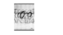
次に、実施例、比較例のガラス板について、ガラス板端面に形成される凹部の有無を顕微鏡画像により検査した。また、ガラス板端面の凹部領域が主表面に至っているか否かもSEM画像により確認した。さらに、実施例、比較例のガラス板について、3点曲げ強度を実施した。なお、3点曲げ強度とは、6mm□、板厚0.1mmのガラス板を距離2.5mmに配置した2支点上に置き、支点間の中央の1点にクロスヘッド速度0.5mm/minで荷重を加え、ガラスが破壊された際の破壊荷重(単位N/mm2)の20回繰り返し測定の平均値である。その結果を表1に示す。また、実施例のガラス板端面のレーザー顕微鏡画像を図9に示す。

表1、図9に示すように、実施例は、凹部が存在し、凹部領域も主表面に至っていなかったため、曲げ強度が329MPaと高かった。一方、比較例は、凹部が存在しなかったため、曲げ強度が224MPaと低かった。
参考として、本発明のガラス板のガラス組成例を表2~5に示す。


1 ガラス板
1a 第1の主表面
1b 第2の主表面
1c 端面
1d 第1の端縁部
1e 第2の端縁部
2 凹部領域
3 改質部
10 ガラス板
10a エッチング前のガラス板
20 母材
21 支持体
22 押圧部材
23 ブレード
R 凹部
R1 第一凹部
C 凹部の頂部外周
D エッチング槽
E エッチング液
1a 第1の主表面
1b 第2の主表面
1c 端面
1d 第1の端縁部
1e 第2の端縁部
2 凹部領域
3 改質部
10 ガラス板
10a エッチング前のガラス板
20 母材
21 支持体
22 押圧部材
23 ブレード
R 凹部
R1 第一凹部
C 凹部の頂部外周
D エッチング槽
E エッチング液
Claims (16)
- 表裏一対の主表面と、前記一対の主表面各々の端部を結ぶ端面とを備えたガラス板において、
前記端面は、複数の凹部からなる凹部領域を有し、
前記凹部領域の任意の30μm□の範囲内に含まれる前記凹部のうち、頂部外周上の二地点間の直線距離の最大値が0.5μm以上となる第一凹部の割合が50%以上であり、
前記凹部領域が前記主表面に至っていないことを特徴とするガラス板。 - 前記凹部領域の任意の30μm□の範囲内に含まれる前記凹部の総数が、1個以上300個以下であることを特徴とする請求項1に記載のガラス板。
- 前記第一凹部の深さが0.5μm以上であることを特徴とする請求項1又は2に記載のガラス板。
- 厚み方向における前記端面の中心と、厚み方向における前記凹部領域の中心とが同じ位置であることを特徴とする請求項1~3のいずれかに記載のガラス板。
- (前記凹部領域の深さD(μm))/(前記凹部領域の幅W(μm))が0.03以上であることを特徴とする請求項1~4のいずれかに記載のガラス板。
- 厚みが0.3mm以下であることを特徴とする請求項1~5のいずれかに記載のガラス板。
- 3点曲げ強度が285N/mm2以上であることを特徴とする請求項1~6のいずれかに記載のガラス板。
- 少なくとも一方の前記主表面に光学膜が形成されていることを特徴とする請求項1~7のいずれかに記載のガラス板。
- 前記光学膜が、反射防止膜、可視光遮蔽膜、近赤外線遮蔽膜、紫外線遮蔽膜、紫外線及び近赤外線遮蔽膜の少なくとも1種であることを特徴とする請求項8に記載のガラス板。
- 前記ガラス板が、組成として質量%でP2O5を10%以上含むことを特徴とする請求項1~9のいずれかに記載のガラス板。
- 厚み0.05mm換算、波長400nmにおける光透過率が80%以上であることを特徴とする請求項1~10のいずれかに記載のガラス板。
- 厚み0.05mm換算、波長800nmにおける光透過率が50%以下であることを特徴とする請求項1~11のいずれかに記載のガラス板。
- 近赤外線吸収ガラスであることを特徴とする請求項1~12のいずれかに記載のガラス板。
- 表裏一対の主表面を備えたガラス板の母材を用意する工程と、
前記母材にレーザー光を照射することにより、前記母材の内部に改質部を設ける工程と、
前記改質部が設けられている部分に沿い前記母材を割断してガラス板を得る工程と、
前記母材の割断により生じた前記ガラス板の端面をエッチング液に接触させてエッチングするエッチング工程を備え、
前記改質部を設ける工程において、前記改質部が前記一対の主表面に至らないように設け、
前記ガラス板が、リン酸塩系ガラスからなり、
前記エッチング液が、アルカリ洗剤であり、
前記ガラス板の前記端面の前記エッチング液による除去厚みが、1μm以上であることを特徴とするガラス板の製造方法。 - 前記エッチング液が、アルカリ成分としてキレート剤のアルカリ塩を含むことを特徴とする請求項14に記載のガラス板の製造方法。
- 前記エッチング工程の前に、前記ガラス板の少なくとも一方の主表面に光学膜を形成する成膜工程を備えていることを特徴とする請求項14又は15に記載のガラス板の製造方法。
Applications Claiming Priority (4)
| Application Number | Priority Date | Filing Date | Title |
|---|---|---|---|
| JP2019054419 | 2019-03-22 | ||
| JP2019-054419 | 2019-03-22 | ||
| JP2020008478A JP7445189B2 (ja) | 2019-03-22 | 2020-01-22 | ガラス板及びその製造方法 |
| JP2020-008478 | 2020-01-22 |
Publications (1)
| Publication Number | Publication Date |
|---|---|
| WO2020195438A1 true WO2020195438A1 (ja) | 2020-10-01 |
Family
ID=72609451
Family Applications (1)
| Application Number | Title | Priority Date | Filing Date |
|---|---|---|---|
| PCT/JP2020/007202 Ceased WO2020195438A1 (ja) | 2019-03-22 | 2020-02-21 | ガラス板及びその製造方法 |
Country Status (1)
| Country | Link |
|---|---|
| WO (1) | WO2020195438A1 (ja) |
Cited By (1)
| Publication number | Priority date | Publication date | Assignee | Title |
|---|---|---|---|---|
| WO2025023184A1 (ja) * | 2023-07-24 | 2025-01-30 | Agc株式会社 | ガラス、近赤外線吸収カットフィルタ及び固体撮像素子 |
Citations (6)
| Publication number | Priority date | Publication date | Assignee | Title |
|---|---|---|---|---|
| JP2005219960A (ja) * | 2004-02-05 | 2005-08-18 | Nishiyama Stainless Chem Kk | ガラスの切断分離方法、フラットパネルディスプレイ用ガラス基板、フラットパネルディスプレイ |
| WO2015046088A1 (ja) * | 2013-09-25 | 2015-04-02 | 旭硝子株式会社 | 光学ガラス |
| WO2015182300A1 (ja) * | 2014-05-29 | 2015-12-03 | 旭硝子株式会社 | 光学ガラスおよびガラス基板の切断方法 |
| JP2017190282A (ja) * | 2016-04-11 | 2017-10-19 | 日本電気硝子株式会社 | 赤外線吸収ガラス板及びその製造方法、並びに固体撮像素子デバイス |
| WO2019065100A1 (ja) * | 2017-09-27 | 2019-04-04 | 日本電気硝子株式会社 | ガラス板及びその製造方法 |
| JP2019064883A (ja) * | 2017-10-04 | 2019-04-25 | 日本電気硝子株式会社 | ガラス及びその製造方法 |
-
2020
- 2020-02-21 WO PCT/JP2020/007202 patent/WO2020195438A1/ja not_active Ceased
Patent Citations (6)
| Publication number | Priority date | Publication date | Assignee | Title |
|---|---|---|---|---|
| JP2005219960A (ja) * | 2004-02-05 | 2005-08-18 | Nishiyama Stainless Chem Kk | ガラスの切断分離方法、フラットパネルディスプレイ用ガラス基板、フラットパネルディスプレイ |
| WO2015046088A1 (ja) * | 2013-09-25 | 2015-04-02 | 旭硝子株式会社 | 光学ガラス |
| WO2015182300A1 (ja) * | 2014-05-29 | 2015-12-03 | 旭硝子株式会社 | 光学ガラスおよびガラス基板の切断方法 |
| JP2017190282A (ja) * | 2016-04-11 | 2017-10-19 | 日本電気硝子株式会社 | 赤外線吸収ガラス板及びその製造方法、並びに固体撮像素子デバイス |
| WO2019065100A1 (ja) * | 2017-09-27 | 2019-04-04 | 日本電気硝子株式会社 | ガラス板及びその製造方法 |
| JP2019064883A (ja) * | 2017-10-04 | 2019-04-25 | 日本電気硝子株式会社 | ガラス及びその製造方法 |
Cited By (1)
| Publication number | Priority date | Publication date | Assignee | Title |
|---|---|---|---|---|
| WO2025023184A1 (ja) * | 2023-07-24 | 2025-01-30 | Agc株式会社 | ガラス、近赤外線吸収カットフィルタ及び固体撮像素子 |
Similar Documents
| Publication | Publication Date | Title |
|---|---|---|
| JP6137202B2 (ja) | ガラス基板の切断方法、ガラス基板、近赤外線カットフィルタガラス、ガラス基板の製造方法 | |
| JP6811053B2 (ja) | 赤外線吸収ガラス板及びその製造方法、並びに固体撮像素子デバイス | |
| TWI791530B (zh) | 紅外線吸收玻璃板及其製造方法、以及固體攝像元件裝置 | |
| CN106414352A (zh) | 光学玻璃及玻璃基板的切断方法 | |
| KR102555595B1 (ko) | 유리판 및 그 제조 방법 | |
| JP7445189B2 (ja) | ガラス板及びその製造方法 | |
| TWI753884B (zh) | 紅外線吸收玻璃板及其製造方法、以及固體攝像元件裝置 | |
| JP7054066B2 (ja) | 光学膜付きガラス板及びその製造方法 | |
| WO2015030015A1 (ja) | 光学多層膜付きガラス部材、近赤外線カットフィルタガラスおよび光学多層膜付きガラス部材の製造方法 | |
| JP6406263B2 (ja) | 光学ガラス | |
| TWI727841B (zh) | 繞射光學元件 | |
| JP7092135B2 (ja) | ガラス | |
| JP2020142952A (ja) | 近赤外線吸収ガラス板 | |
| KR20230017178A (ko) | 지지 유리 기판 및 이것을 사용한 적층 기판 | |
| JP2019014610A (ja) | 光学膜付きガラス部材の製造方法及び光学膜付き母ガラス基板 |
Legal Events
| Date | Code | Title | Description |
|---|---|---|---|
| 121 | Ep: the epo has been informed by wipo that ep was designated in this application |
Ref document number: 20777577 Country of ref document: EP Kind code of ref document: A1 |
|
| NENP | Non-entry into the national phase |
Ref country code: DE |
|
| 122 | Ep: pct application non-entry in european phase |
Ref document number: 20777577 Country of ref document: EP Kind code of ref document: A1 |