WO2020195349A1 - 気化器 - Google Patents
気化器 Download PDFInfo
- Publication number
- WO2020195349A1 WO2020195349A1 PCT/JP2020/006267 JP2020006267W WO2020195349A1 WO 2020195349 A1 WO2020195349 A1 WO 2020195349A1 JP 2020006267 W JP2020006267 W JP 2020006267W WO 2020195349 A1 WO2020195349 A1 WO 2020195349A1
- Authority
- WO
- WIPO (PCT)
- Prior art keywords
- tank
- vaporizer
- heat transfer
- liquid material
- heater
- Prior art date
- Legal status (The legal status is an assumption and is not a legal conclusion. Google has not performed a legal analysis and makes no representation as to the accuracy of the status listed.)
- Ceased
Links
Images




Classifications
-
- B—PERFORMING OPERATIONS; TRANSPORTING
- B01—PHYSICAL OR CHEMICAL PROCESSES OR APPARATUS IN GENERAL
- B01J—CHEMICAL OR PHYSICAL PROCESSES, e.g. CATALYSIS OR COLLOID CHEMISTRY; THEIR RELEVANT APPARATUS
- B01J7/00—Apparatus for generating gases
- B01J7/02—Apparatus for generating gases by wet methods
-
- C—CHEMISTRY; METALLURGY
- C23—COATING METALLIC MATERIAL; COATING MATERIAL WITH METALLIC MATERIAL; CHEMICAL SURFACE TREATMENT; DIFFUSION TREATMENT OF METALLIC MATERIAL; COATING BY VACUUM EVAPORATION, BY SPUTTERING, BY ION IMPLANTATION OR BY CHEMICAL VAPOUR DEPOSITION, IN GENERAL; INHIBITING CORROSION OF METALLIC MATERIAL OR INCRUSTATION IN GENERAL
- C23C—COATING METALLIC MATERIAL; COATING MATERIAL WITH METALLIC MATERIAL; SURFACE TREATMENT OF METALLIC MATERIAL BY DIFFUSION INTO THE SURFACE, BY CHEMICAL CONVERSION OR SUBSTITUTION; COATING BY VACUUM EVAPORATION, BY SPUTTERING, BY ION IMPLANTATION OR BY CHEMICAL VAPOUR DEPOSITION, IN GENERAL
- C23C16/00—Chemical coating by decomposition of gaseous compounds, without leaving reaction products of surface material in the coating, i.e. chemical vapour deposition [CVD] processes
- C23C16/44—Chemical coating by decomposition of gaseous compounds, without leaving reaction products of surface material in the coating, i.e. chemical vapour deposition [CVD] processes characterised by the method of coating
- C23C16/448—Chemical coating by decomposition of gaseous compounds, without leaving reaction products of surface material in the coating, i.e. chemical vapour deposition [CVD] processes characterised by the method of coating characterised by the method used for generating reactive gas streams, e.g. by evaporation or sublimation of precursor materials
-
- H—ELECTRICITY
- H10—SEMICONDUCTOR DEVICES; ELECTRIC SOLID-STATE DEVICES NOT OTHERWISE PROVIDED FOR
- H10P—GENERIC PROCESSES OR APPARATUS FOR THE MANUFACTURE OR TREATMENT OF DEVICES COVERED BY CLASS H10
- H10P14/00—Formation of materials, e.g. in the shape of layers or pillars
- H10P14/60—Formation of materials, e.g. in the shape of layers or pillars of insulating materials
Definitions
- the present invention relates to a vaporizer. More specifically, the present invention relates mainly to a vaporizer incorporated and used in a semiconductor manufacturing apparatus, a flat panel display manufacturing apparatus, and the like.
- a vaporizer is a device that heats a material that is in a liquid phase state at room temperature (hereinafter referred to as "liquid material”) to generate gas, and supplies the generated gas to the outside.
- a vaporizer is composed of a tank that heats a liquid material to generate gas, a valve that starts and stops the supply of gas generated in the tank, and a flow rate control means that controls the flow rate of gas.
- the vaporizer is incorporated and used in, for example, a semiconductor manufacturing apparatus and a flat panel display manufacturing apparatus, for the purpose of supplying gas as a raw material for semiconductors and optical fibers.
- a heater can be inserted into a hole or groove provided in a manifold block or the like having a main body of a flow control means and / or a device mounting surface to heat a gas flow path. The invention of the vaporizer is described.
- Patent Document 3 describes an invention of a vaporizer capable of supplying gas to the outside by using an internal flow path provided inside the outer wall of the tank. According to this, since it is not necessary to provide a pipe for providing the valve unit between the tank and the mass flow controller, it is possible to prevent gas liquefaction in the pipe and to make the vaporizer compact.
- Patent Document 4 describes an invention of a vaporizer capable of heating a conduit by using a heater plate configured by attaching a rubber heater to a flat aluminum-based material.
- the heater plate formed by attaching the rubber heater to the flat aluminum-based material is simple and compact, and the above-mentioned problems have not been a concern.
- the size of the tank provided in the vaporizer must be reduced inevitably.
- a flat rubber heater or the like provided on the outside of the tank is used.
- the surface area of the tank to which the rubber heater can be attached also becomes smaller, so that the amount of heat supplied to the liquid material in the tank per unit time also becomes smaller than before.
- the amount of gas that the vaporizer can generate per unit time is smaller than that in the past, there is a problem that the manufacturing efficiency of the semiconductor is lowered.
- the volume of liquid material that can be stored in the tank also becomes smaller. Then, the liquid material in the tank will be depleted in a shorter time due to the consumption of the liquid material due to the operation of the vaporizer. Therefore, in order to keep the accumulated amount of the liquid material in the tank constant, the liquid material is more frequently used than before. Will need to be replenished in the tank.
- the liquid material supplied into the tank from the outside is not heated, and the temperature of the liquid material is lower than the temperature of the liquid material in the tank, so that a new liquid material is supplied. As a result, the temperature of the liquid material in the tank is lowered, and there is a problem that the gas generation efficiency is further lowered.
- the present invention has been made in view of the above-mentioned problems, and the gas condenses even when the width is reduced by using a heater which has a simple structure and can be easily manufactured.
- One purpose is to provide a vaporizer that can prevent it from returning to liquid.
- another invention of the present invention is to provide a vaporizer capable of maintaining a gas generation efficiency equivalent to that of the conventional vaporizer even in a vaporizer provided with a tank having a smaller size than the conventional one. The purpose.
- the vaporizer (1a) includes a tank (2) that heats a liquid material to generate gas, and a gas supply valve (3a) that starts or stops the supply of the generated gas.
- the gas supply valve (3a) and the flow control means (4) are fixed to the fixing member (5), and the fixing member (5) is not fixed to the gas supply valve (3a) and the flow control means (4).
- a flat fixing member heater (5a) is provided on the surface of the gas supply valve (3a) and the flow control means (4) are in contact with one or more heat transfer plates (6).
- At least one of the heat transfer plates (6) is provided with a flat heat transfer plate heater (6a) on a surface on the side not in contact with the gas supply valve (3a) and the flow control means (4).
- the vaporizer (1a) according to the present invention is provided with heaters (2a, 5a, 6a) at at least three places, and has a simple structure, and even when the width is reduced, the pipe and the tank (2) can be used. On the other hand, a sufficient amount of heat can be given.
- one surface (2b) of the surfaces constituting the tank (2) is a gas supply valve (3a) and a flow rate control means (4).
- the side extending in the direction and provided with the fixing member heater (5a) of the fixing member (5) may be fixed to the extended surface (2b). According to this configuration, heat is transferred from the tank (2) to the fixing member (5), so that the piping is heated more uniformly.
- the vaporizer (1b) according to the present invention is provided inside the tank (2) in addition to the above configuration, is configured to be thermally conductive with the tank heater (2a), and is made of a metal or alloy. It further comprises one or more heat transfer members (10). According to this configuration, the heat supplied from the tank heater (2a) is efficiently transferred to the liquid material in the tank (2) via the heat transfer member (10).
- the liquid material charge pipe (9c) which is a pipe for supplying the liquid material to the tank (2), further includes an auxiliary heater (9h). According to this configuration, the liquid material newly supplied to the tank (2) can be preheated by the auxiliary heater (9h).
- a vaporizer capable of reliably preventing gas from condensing in a pipe by a heating means having a simple structure. Furthermore, even in a carburetor whose width in the left-right direction is smaller than before, and therefore the size of the tank is small, the liquid material stored in the tank can be efficiently heated to maintain the gas generation efficiency at a high level. Can be done.
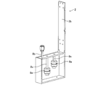
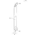
- FIG. 1 It is a perspective view which shows the example of the tank (2) of the vaporizer (1a) which concerns on 3rd Embodiment of this invention. It is a perspective view which shows the example of the plate-shaped member (5b) which comprises the fixing member (5) of the vaporizer (1a) which concerns on 4th Embodiment of this invention. It is a right side view which shows the example of the plate-shaped member (5b) which comprises the fixing member (5) of the vaporizer (1a) which concerns on 4th Embodiment of this invention.
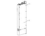
- FIG. 1 is a perspective view showing an example of the appearance of the vaporizer (1) according to the present invention.
- the vaporizer (1) is housed in a case (7) having a rectangular parallelepiped shape as a whole.
- the case (7) has a shape in which the width in the left-right direction is short and the height in the up-down direction is long when viewed from the front.
- the outer dimensions of the case (7) excluding the protruding portion are, for example, a width of 50 mm, a depth of 180 mm, and a height of 600 mm.
- the vaporizer (1) according to the present invention is characterized in that the dimension in the width direction is smaller than that of the conventional vaporizer. Therefore, a larger number of vaporizers (1) can be installed side by side in the same installation width as compared with the conventional vaporizers.
- the surface on the back side of the vaporizer (1) when viewed from the front is a surface to be fixed in contact with the wall surface, etc., and the wall surface, etc. is used by using the fixing members protruding upward and downward from the case (7). Can be fixed to.
- On the upper surface of the vaporizer (1) for example, a connection portion of a gas pipe for supplying gas to the outside or sending purge gas to the inside and a connector for exchanging an electric signal with the inside of the vaporizer (1). Etc. are provided.
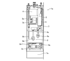
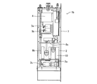
- FIG. 2 is a right side view showing an example of the internal structure of the vaporizer (1a) according to one embodiment of the present invention (hereinafter, may be referred to as “first embodiment”). .. That is, the panel constituting the right side surface of the case (7) shown in FIG. 1 is removed so that the internal structure of the vaporizer (1a) according to the first embodiment can be seen.
- the vaporizer (1a) includes a tank (2) that heats a liquid material to generate gas, a gas supply valve (3a) that starts or stops the supply of the generated gas, and a gas. It is provided with a flow rate control means (4) for controlling the flow rate of the gas flowing out from the supply valve (3a).
- Tank (2) is a container for storing liquid materials.
- the tank (2) is provided with an inlet for charging the liquid material and an outlet for discharging the generated gas.
- a liquid material charging pipe (9c) which is a pipe for charging the liquid material, can be provided between the inlet for charging the liquid material and the front surface or the upper surface of the case (7).
- the liquid material can be charged into the tank (2) from a storage means (not shown) via the liquid material charge tube (9c).
- a charge valve (3c) may be provided in the middle of the liquid material charge pipe (9c).
- the tank (2) Since the tank (2) is a component whose purpose is to store the liquid material and heat the liquid material to generate gas, it is made of a material having excellent corrosion resistance to the liquid material even at a high temperature. , It is required to have a structure that can withstand an increase in internal pressure. Therefore, the tank (2) can be assembled by welding, for example, a stainless steel plate having a thickness of 5.0 mm.
- the shape of the tank (2) is preferably a rectangular parallelepiped shape that can be stored inside the case (7) because a large internal volume can be secured.
- the tank (2) can be provided with various sensors (8) according to various purposes.
- the tank (2) may be provided with one or more liquid level sensors (8a) to know the stored amount of the charged liquid material.
- the tank (2) may be provided with a temperature sensor (8b) for measuring the temperature of the liquid material and / or a pressure sensor (8c) for measuring the pressure of the gas generated in the tank (2).
- a liquid reservoir (7a) can be provided at a position lower than the tank (2) in the case (7) in case the liquid material leaks from the tank (2) to the outside.
- the gas supply valve (3a) is a valve that starts or stops the supply of gas generated in the tank (2).
- the gas supply valve (3a) can be provided between the flow rate control means (4) and the tank (2), which will be described later.
- any type of valve may be used as long as the fluid resistance when opened is small and the gas can flow smoothly.
- known means such as those using compressed air and a cylinder or those using an electric actuator can be used.
- the flow rate control means (4) controls the flow rate of the gas flowing out from the gas supply valve (3a).
- the flow rate control means (4) it is preferable to use a known mass flow controller.
- the mass flow controller is composed of a flow rate sensor that measures the flow rate of gas, a flow rate control valve that controls the flow rate of gas based on the output from the flow rate sensor, a control circuit that controls these, and the like.
- the mass flow controller (4) used in the vaporizer (1a) according to the first embodiment is preferably configured so as to be able to control the flow rate of the gas heated to, for example, 120 ° C.
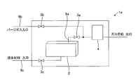
- FIG. 3 is a schematic view showing an example of piping of the vaporizer (1a) according to the first embodiment.
- FIG. 3 schematically shows the connection state of the tank (2) and the pipes around it, and does not show the actual position and direction of the pipes.
- the tank (2) is provided with an inlet for charging the liquid material and an outlet for discharging the generated gas.
- a charge valve (3c) is provided in the middle of the liquid material charge pipe (9c), which is a pipe connecting the inlet of the tank (2) and the outside.
- the liquid material is stored inside the tank (2) through the liquid material charge tube (9c). From the viewpoint of preventing the liquid level from being disturbed, it is preferable that the inlet of the tank (2) is provided at the bottom of the tank (2).
- a gas supply valve (3a) is provided in the middle of the gas supply pipe (9a), which is a pipe connecting the outlet of the tank (2) and the outside, and the gas supply valve (3a) and the outside are connected.
- a flow rate control means (4) is provided between them.
- the gas generated in the tank (2) is guided to the outside of the vaporizer (1a) through the gas supply valve (3a) and the flow rate control means (4), and is supplied to the semiconductor manufacturing apparatus or the like.
- the purge gas supply pipe (9b) which is a pipe for the purge gas.
- the purge gas supply pipe (9b) is provided between the connection portion and the outside.
- a purge valve (3b) is provided in the middle of the purge gas supply pipe (9b).
- the tank (2) includes a flat tank heater (2a) for heating the liquid material.
- the flat tank heater (2a) is provided in contact with the outer wall of the container constituting the tank (2), and the liquid material inside the tank (2) can be indirectly heated by heating the container. Any heater may be used as long as it is possible.
- the flat tank heater (2a) is preferable because it does not require much installation volume of the heater.
- a rubber heater having a thickness of 1.5 mm can be used as the tank heater (2a).
- the rubber heater is formed by sandwiching a wire-shaped or foil-shaped resistance heating element between heat-resistant rubbers. Generally, the maximum amount of heat generated per square centimeter of a rubber heater is about 1 watt, and the heat resistant temperature is about 200 ° C.
- the tank heater (2a) is preferably provided on the surface of the tank (2) at a position below the liquid level of the liquid material.
- the tank heater (2a) can be provided, for example, on the bottom surface or the side surface of the tank (2).
- the tank heater (2a) is provided on the side surface of the tank (2), if it is provided on the side surface in the left-right direction when viewed from the front of the vaporizer (1a), the width of the tank (2) in the left-right direction is reduced accordingly. Since the volume of the tank (2) is also small, it is preferable to provide it only on the side surface in the front-rear direction.
- the tank heater (2a) is provided on the bottom surface of the tank (2).
- the flat tank heater (2a) is illustrated, but a rod-shaped heater provided inside the tank (2) and capable of directly heating the liquid material is adopted as the tank heater (2a). You may.
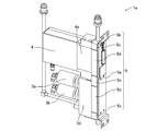
- FIG. 4 is a perspective view showing an example of a portion including a fixing member (5) of the vaporizer (1a) according to the first embodiment.
- the fixing member (5) can be composed of a plate-shaped member (5b) and a plurality of joint blocks (5c) fixed to the plate-shaped member (5b).
- the plate-shaped member (5b) is an elongated plate-shaped member on which the gas supply valve (3a) and the flow rate control means (4) can be placed via the joint block (5c), and the width thereof is from the front. It is smaller than the width of the vaporizer (1a) when viewed.
- the joint block (5c) is a member having a rectangular parallelepiped shape in which a gas flow path is formed inside.
- the bottom surface of the joint block (5c) is fixed to the plate-shaped member (5b) using screws or the like.
- the surface of the joint block (5c) opposite to the bottom surface is fixed with screws or the like so that the bottom of the gas supply valve (3a) and the flow rate control means (4) and the gas flow path coincide with each other.
- the gas flow paths of the gas supply valve (3a) and the flow rate control means (4) are connected by the flow path of the joint block (5c) arranged between them.
- the gas supply valve (3a) can be fixed to the base member (3d) alone or together with the purge valve (3b), and can be fixed to the joint block (5c) via the base member (3d).
- the flow rate control means (4) can also be fixed to the joint block (5c) via the base portion (4a).
- the portion where the gas supply valve (3a), the flow rate control means (4) and the fixing member (5) illustrated in FIG. 4 are combined with each other may be referred to as an "integrated gas supply system".
- the integrated gas supply system uses a joint block (5c) to reduce the size of the piping and facilitate the connection, and installs a gas line for handling many types of gas at the same time in a smaller area than before. be able to.
- the integrated gas supply system is distributed as individual components or as a unit including the entire system, and by using these, the manufacturing cost of the vaporizer can be reduced.
- the fixing member (5) is provided with a flat fixing member heater (5a) on a surface on the side that is not fixed to the gas supply valve (3a) and the flow rate control means (4).
- the gas supply valve (3a) of the plate-shaped member (5b) included in the fixing member (5) and the flat fixing member heater (5a) are arranged on the surface opposite to the flow rate control means (4). Will be set up.
- the plurality of joint blocks (5c) included in the fixing member (5) are heated, and the gas flow path, the gas supply valve (3a), and the flow rate control means (4) provided inside the joint block (5c) are heated. ) Can be prevented from condensing the gas flowing through the gas flow path provided inside.
- the fixing member heater (5a) is provided in contact with the plate-shaped member (5b) included in the fixing member (5), and the gas flow path and the gas supply valve (3a) provided inside the joint block (5c). Any heater may be used as long as the gas can be indirectly heated by heating the gas flow path provided inside the flow rate control means (4).
- the flat fixing member heater (5a) is preferable because it does not require much installation volume of the heater.
- a rubber heater having a thickness of 1.5 mm can be used as in the tank heater (2a).
- the gas generated in the container of the tank (2) stays in the space above the liquid level of the liquid material in the container, and then the gas supply valve from the outlet provided in the tank (2) via the pipe. It is supplied to the outside through (3a) and the flow rate control means (4). Therefore, it is preferable that the pipe at the outlet from the tank (2) is provided on the upper surface side of the container of the tank (2). Along with this, it is preferable that the gas supply valve (3a) and the flow rate control means (4) are also provided above the tank (2).
- the gas supply valve (3a) and the flow rate control means (4) are in contact with one or more heat transfer plates (6), and at least one of the heat transfer plates (6) is heat-transferred.
- the plate (6) is provided with a flat heat transfer plate heater (6a) on a surface on the side not in contact with the gas supply valve (3a) and the flow rate control means (4).
- FIG. 5 is a perspective view of a portion including the fixing member (5) of the vaporizer (1a) according to the first embodiment illustrated in FIG. 4 as viewed from another angle. As illustrated in FIG. 5, the gas supply valve (3a) and the flow rate control means (4) are in contact with one or more heat transfer plates (6).
- the number of heat transfer plates (6) in contact with the gas supply valve (3a) and the flow rate control means (4) may be one or two or more.
- two heat transfer plates (6) are provided so as to sandwich the base member (3d) of the gas supply valve (3a) and the base portion (4a) of the flow rate control means (4) from both sides. Has been done.
- the heat transfer plate (6) is preferably made of a material having high thermal conductivity so that heat from the heat transfer plate heater (6a) described later can be easily transferred.
- the heat transfer plate (6) can be made of, for example, aluminum or copper or an alloy thereof. As the aluminum alloy, for example, 5052 material, which is a general material, can be used.
- the thickness of the heat transfer plate (6) is preferably 1.6 mm or more and 2.0 mm or less, for example. By setting the thickness of the heat transfer plate (6) to 1.6 mm or more, the heat capacity of the heat transfer plate (6) increases, which is advantageous for heat retention. By setting the thickness of the heat transfer plate (6) to 2.0 mm or less, the heat transfer plate (6) can be easily processed.
- At least one heat transfer plate (6) of the heat transfer plates (6) has a flat heat transfer plate heater (6a) on the surface not in contact with the gas supply valve (3a) and the flow rate control means (4). ) Is provided.
- the heat transfer plate heater (6a) is supplied from the heat transfer plate heater (6a). By supplementing the heat generated, it is possible to more reliably prevent gas from condensing in the flow path.
- the heat transfer plate heater (6a) is provided in contact with the heat transfer plate (6), and the gas flow path, the gas supply valve (3a), and the flow rate control means (4) provided inside the joint block (5c). Any heater may be used as long as the gas can be indirectly heated by heating the gas flow path provided inside the.
- the flat heat transfer plate heater (6a) is preferable because it does not require much heater installation volume.
- a rubber heater having a thickness of 1.5 mm can be used as in the case of the tank heater (2a) and the fixed member heater (5a).
- the position where the heat transfer plate heater (6a) is provided is the side of at least one of the heat transfer plates (6) that is not in contact with the gas supply valve (3a) and the flow rate control means (4). Is the aspect of. If the heat transfer plate heater (6a) is provided in direct contact with the gas supply valve (3a) and / or the flow rate control means (4), it is difficult to remove these members for the purpose of inspection and / or repair, for example. It becomes. If the heat transfer plate heater (6a) is provided on the surface of the heat transfer plate (6) that is not in contact with the gas supply valve (3a) and the flow control means (4), the heat transfer plate (6) can be removed. Since the heat transfer plate heater (6a) can be removed at the same time, inspection and repair of these members can be facilitated.
- the heat transfer plate heater (6a) can heat the gas flow path from two directions together with the fixing member heater (5a). Therefore, the effect of the present invention can be achieved. If there are two heat transfer plates (6) and the capacity for installing the heat transfer plate heater (6a) can be secured, heat transfer plate heaters (6a) are provided on both of the two heat transfer plates (6). , The gas flow path may be heated from three directions together with the fixing member heater (5a).
- the gas generated by heating the liquid material by the tank heater (2a) is generated by the fixing member heater (5a) and the heat transfer plate heater. It can be heated from at least two directions of (6a). Therefore, even when the width of the vaporizer is reduced, the gas can be stably supplied while preventing the gas from condensing in the flow path.
- the vaporizer (1a) according to another embodiment of the present invention (hereinafter, may be referred to as "second embodiment") includes the gas supply valve (3a) and the fixing member of the first embodiment.
- the vaporizer (1a) is provided with a heat transfer block (5d) in at least one of the space between (5) and the flow rate control means (4) and the fixing member (5).
- the gas supply valve (3a) and the fixing member (5) are illustrated as illustrated in FIG. There may be a space between the airflow control means (4) and the fixing member (5).
- the heat transfer block (5d) is preferably made of a material having high thermal conductivity, similarly to the heat transfer plate (6) described above.
- a heat transfer block (5d) in at least one of the space between the gas supply valve (3a) and the fixing member (5) and the space between the flow rate control means (4) and the fixing member (5). Since the heat conduction of the portion is improved, the effect of the present invention can be achieved. It is more preferable to provide a heat transfer block (5d) in both of these spaces because the heat conduction in all the spaces is improved.
- the shape of the heat transfer block (5d) is preferably a shape and a size that can be inserted into the space without a gap.
- the vaporizer (1a) according to another embodiment of the present invention (hereinafter, may be referred to as a "third embodiment") is a tank (hereinafter, a tank of the first embodiment or the second embodiment).
- One surface (2b) of the surfaces constituting 2) extends in the direction of the gas supply valve (3a) and the flow rate control means (4), and the fixing member heater (5a) of the fixing member (5)
- the provided side is a vaporizer (1a) fixed to the extended surface (2b).
- FIG. 6 is a perspective view showing an example of a tank of the vaporizer (1a) according to the third embodiment.
- FIG. 6 is composed of six plates, of which one surface (2b) extends further upward in the figure from the container portion of the tank (2). are doing.
- the extended surface (2b) is composed of a seamless plate from the container portion to the upper end of the tank (2).
- FIG. 6 in order to show the internal structure of the tank (2), one of the six plates constituting the container portion of the tank (2) on the front side toward the drawing is omitted. ing.
- the side of the fixing member (5) provided with the fixing member heater (5a) is fixed to the extended surface (2b). That is, the side of the fixing member (5) illustrated in FIG. 5 provided with the fixing member heater (5a) is fixed to the extended surface (2b) of the tank (2) illustrated in FIG.
- the extended surface (2b) of the tank (2) is directed toward the gas supply valve (3a) and the flow rate control means (4) fixed to the fixing member (5). It will be stretched.
- the gas supply valve (3a) and the flow rate control means (4) are preferably provided above the tank (2), so that the extended surface (2b) of the tank (2) is shown in FIG. As illustrated, it is preferable that the tank (2) further extends upward in the figure from the container portion. Further, it is preferable that the portion forming the container of the tank (2) on the elongated surface (2b) and the other portion have the same thickness.
- the extended surface (2b) of the tank (2) and the fixing member heater (5a) are fixed at positions facing each other.
- the extended surface (2b) of the tank (2) exists between the fixing member heater (5a) and the case (7).
- the extended surface (2b) is composed of a seamless plate from the container portion to the upper end of the tank (2). Therefore, the heat of the liquid material warmed by the tank heater (2a) is transferred to the entire member constituting the tank (2), and the extended surface (2b), which is a portion where the fixing member (5) is fixed, is also transferred. It can be warmed up.
- the heat generated in the fixing member heater (5a) is prevented from escaping in the direction of the case (7).
- the heat generated in the fixing member heater (5a) is efficiently transferred to the fixing member (5) side, and the coagulation of gas in the flow paths of the gas supply valve (3a) and the flow rate control means (4) is more reliable. Can be prevented.
- the fixing member (5) and the tank (2) are firmly fixed by directly fixing the fixing member (5) to the extended surface (2b), the mechanical strength of the entire vaporizer (1a) is as good as possible. Will increase.
- the vaporizer (1a) according to another embodiment of the present invention is the elongated surface (2b) of the third embodiment. It is a vaporizer (1a) in which a space exists between the fixing member heater (5a) and the heater (5a).
- FIG. 7 is a perspective view showing only the plate-shaped member (5b) constituting the fixing member (5) of the vaporizer (1a) according to the present invention illustrated in FIG.
- a flat surface portion (5b1) for fixing the gas supply valve (3a) and the flow rate control means (4) and a flat surface portion (5b1) are extended via the joint block (5c).
- the plate-shaped member (5b) can be formed by the legs (5b2) provided at both ends of the flat surface portion (5b1) so as to create a space between the surface (2b) and the surface (2b).
- the legs can be extended as shown in FIG. 8 even when the fixing member heater (5a) is provided.
- a space (5s) is created between the surface (2b) and the fixing member heater (5a) (see the shaded area). Since it is difficult for the space (5s) to transfer heat, the presence of the space (5s) further prevents heat from escaping from the surface of the fixing member heater (5a) toward the extended surface (2b) of the tank (2).
- the vaporizer (1a) according to another embodiment of the present invention (hereinafter, may be referred to as a "fifth embodiment") is any one of the first to fourth embodiments.
- the tank (2) of the embodiment is provided with one or more liquid level sensors (8a), and one end of the stem (8s) to which the liquid level sensor (8a) is attached is of the tank (2).
- the vaporizer (1a) is fixed to the upper surface side of the inside and the other end of the stem (8s) is not in contact with the lower surface side of the inside of the tank (2).
- the liquid level sensor (8a) can be configured by a substantially cylindrical float attached so that it can move up and down along the stem (8s).
- the float of the liquid level sensor (8a) moves up and down as the liquid level of the liquid material fluctuates, and a lead provided inside the stem (8s) by a magnetic field generated from a permanent magnet provided inside the float.
- the switch is activated. As a result, an electric signal corresponding to the position of the liquid level can be generated.
- a stopper is provided on the bottom of the stem (8s) to prevent the float from falling off.
- the tank heater (2a) can be provided on the bottom surface of the tank (2), for example.
- the tank heater (2a) is provided on the bottom surface of the tank (2), if both ends of the stem (8s) are fixed to both the upper surface side and the lower surface side inside the tank (2), the tank heater (2a) The heat of the tank (2) is transmitted through the stem (8s) and easily escapes from the lower surface side to the upper surface side of the tank (2).
- the vaporizer (1a) according to the fifth embodiment, one end of the stem (8s) is fixed to the upper surface side inside the tank (2), and the other end of the stem (8s) is the tank (2). ) Is not in contact with the lower surface side.
- the heat of the tank heater (2a) is prevented from being transmitted through the stem (8s) and escaping from the lower surface side to the upper surface side of the tank (2), so that the heat generated from the tank heater (2a) is transferred to the tank (2). It can be used without waste for heating the liquid material stored inside the stem.
- ⁇ 6th Embodiment By the way, as described at the beginning of this specification, the width in the left-right direction when the vaporizer is viewed from the front is reduced so that the overall width does not become too large even when a large number of vaporizers are installed side by side. There is a growing demand for it. In order to meet such demands, the tank provided in the vaporizer must be inevitably made smaller. In that case, the means for heating the liquid material in the tank (for example, a rubber heater or the like) has to be miniaturized, and the amount of heat supplied to the liquid material in the tank per unit time is also smaller than in the conventional case. As a result, the amount of gas that the vaporizer can generate per unit time is smaller than in the conventional case, so that there is a problem that the manufacturing efficiency of the semiconductor is lowered.
- the means for heating the liquid material in the tank for example, a rubber heater or the like
- the vaporizer according to the sixth embodiment of the present invention is the vaporizer (1a) according to any one of the first to fifth embodiments described above, and is provided inside the tank (2).
- a vaporizer (1b) configured to be thermally conductive with a tank heater (2a) and further comprising one or more heat transfer members (10) made of a metal or alloy.
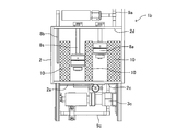
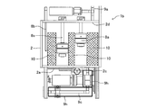
- FIG. 9 is a right side view showing an example of the configuration of the tank (2) of the vaporizer (1b) and the peripheral portion thereof according to the sixth embodiment.
- the vaporizer (1b) is a vaporizer (1a) according to any one of the first to fifth embodiments described above, is provided inside the tank (2), and has a heat conduction with the tank heater (2a).
- a vaporizer (1b) that is capable of being configured and further comprising one or more heat transfer members (10) made of metal or alloy.
- the heat transfer member (10) is provided with mesh-like hatching for the purpose of facilitating the distinction from the other members constituting the vaporizer (1b).
- the illustration and the following description are merely examples of the configuration of the vaporizer (1b), and the specific configuration of the heat transfer member (10) is not limited to the examples.
- the heat transfer member (10) made of metal or alloy has higher thermal conductivity than the liquid material.
- the heat transfer member (10) is provided inside the tank (2) and is configured to be heat conductive with the tank heater (2a). Therefore, the heat generated in the tank heater (2a) is transferred to the heat transfer member (10), the heat transfer member (10) becomes a new heat source, and the heat supplied from the tank heater (2a) is stored in the tank (2). It can be efficiently transmitted to the liquid material. As a result, the liquid material can be heated with higher efficiency than the vaporizer according to the prior art without the heat transfer member (10), so that the gas generation efficiency can be maintained at a high level. ..
- the total number of heat transfer members (10) provided inside the tank (2) may be one or two or more.
- the shapes of the heat transfer members (10) may be the same or different from each other.
- the metal or alloy constituting the heat transfer member (10) it is preferable to use a metal or alloy having excellent corrosion resistance that is not easily corroded by a liquid material such as stainless steel.
- the material constituting one heat transfer member (10) may be one kind of metal or alloy, or may be a combination of a plurality of kinds of metals or alloys.
- the heat transfer member (10) provided inside the tank (2) is preferably provided at a position lower than the liquid level of the liquid material stored in the tank (2) at least in part, and the heat transfer member (10) is preferably provided. ) Is more preferably provided at a position lower than the liquid level.
- the liquid level moves downward due to the consumption of the liquid material, and a part or the whole of the heat transfer member (10) is temporarily above the liquid level. It is permissible to be in a high position.
- the path through which the heat generated in the tank heater (2a) is transmitted to the heat transfer member (10) is not particularly limited.
- the tank heater (2a) is provided on the outer wall of the bottom of the tank (2) and the heat transfer member (10) is provided in contact with the inner wall of the bottom of the tank (2), the tank heater (2a) ( The heat supplied by 2a) is transferred to the heat transfer member (10) via the bottom of the tank (2).
- the heat transfer member (10) may be provided in contact with the inner wall of the surface of the tank (2) where the tank heater (2a) is not provided.
- the heat generated in the tank heater (2a) is transferred to the heat transfer member (10) via the bottom of the tank (2) and / or the liquid material. That is, in any case, the heat transfer member (10) is configured to be heat conductive with the tank heater (2a).
- the heat transfer member (10) may be provided at a position away from the inner wall of the tank (2). In this case, the heat supplied by the tank heater (2a) is transferred to the heat transfer member (10) via the liquid material. That is, even in this case, the heat transfer member (10) is configured to be heat conductive with the tank heater (2a).
- the heat transfer member (10) made of metal or alloy has a higher thermal conductivity than the liquid material and the vaporized gas, so that the heat supplied by the tank heater (2a) is always the heat transfer member. It is transmitted preferentially to (10). As a result, the heat transfer member (10) becomes a new heat source, and heat can be efficiently transferred to the liquid material around the heat transfer member (10) to heat the liquid material.
- the piping of the vaporizer (1b) has the same configuration as the piping of the vaporizer (1a) illustrated in FIG. 3, refer to FIG. 3 for the following explanation.
- a gas supply pipe (9a) a purge gas supply pipe (9b)
- a liquid material charge pipe (9c) is a pipe that supplies the liquid material from the outside to the liquid material supply port (2c) of the tank (2).
- the liquid material charge tube (9c) may be provided with a charge valve (3c) capable of starting or stopping the supply of the liquid material.
- the inlet side of the liquid material charge pipe (9c) is connected to an external storage means (not shown) in which the liquid material is stored.
- the amount of liquid material stored in the tank (2) is detected by a liquid level sensor (8a) or the like, and when the liquid material is insufficient, the charge valve (3c) is opened and the liquid material stored in the storage means is stored in the tank (2). To replenish. When the replenishment of the liquid material is completed, the charge valve (3c) is closed.
- the gas supply pipe (9a) is a pipe for taking out the gas generated in the vaporizer (1b) to the outside and using it.
- the gas supply pipe (9a) may be provided with a gas supply valve (3a) capable of starting or stopping the release of gas.
- a mass flow controller as a flow rate control means (4) capable of controlling the amount of gas released per unit time can be provided.
- the gas supply valve (3a) and the flow rate control means (4) can be operated to take out the required amount of gas when necessary.
- a heating means can be provided in the gas supply pipe (9a) for the purpose of preventing the gas from being cooled and returning to the liquid.
- the purge gas supply pipe (9b) is a pipe that supplies purge gas such as an inert gas for the purpose of discharging the gas remaining inside the gas supply pipe (9a) to the outside.
- the purge gas supply pipe (9b) may be provided with a purge valve (3b) capable of starting or stopping the discharge of the purge gas.
- the purge gas supply pipe (9b) is not an essential component.
- FIG. 10 is a right side view showing an example of the internal structure of the vaporizer (1b) according to the sixth embodiment.
- FIG. 10 in order to show the internal structures of the vaporizer (1b) and the tank (2), a state in which a part of the case (7) of the vaporizer (1b) and the side wall of the tank (2) are removed is shown. Has been done.
- the vaporizer (1b) illustrated in FIG. 10 each component and piping of the above-mentioned vaporizer (1b) are compactly housed in the case (7) with reference to FIGS. 9 and 3.
- the vaporizer (1b) can be provided with a pressure sensor (8c) that measures the pressure of the vaporized gas released from the vaporized gas discharge port (2d).
- the vaporizer (1b) according to the sixth embodiment can also have the same appearance as the vaporizer (1a) illustrated in FIG. That is, the vaporizer (1b) is also suitable for installing a large number of vaporizers side by side in the width direction. Further, in the vaporizer (1b), although the dimension in the width direction is small, the liquid stored in the tank (2) is compared with the vaporizer according to the prior art due to the action of the heat transfer member (10). The material can be efficiently heated to maintain a high level of gas generation efficiency.
- the vaporizer (1b) according to the seventh embodiment is the vaporizer (1b) according to the sixth embodiment described above, wherein the heat transfer member (10) includes a flow path (10a) of a liquid material. It is a vessel (1b).
- the heat transfer member (10) includes a flow path (10a) for the liquid material
- a path through which the liquid material can flow is provided inside the heat transfer member (10).
- a liquid material is replenished at any time from the liquid material supply port (2c), and a flow of substances is formed in which gas is released from the liquid surface of the liquid material.
- the heat transfer member (10) in contact with the liquid material at least in part includes the flow path (10a)
- the liquid material not only flows along the outer surface of the heat transfer member (10) but also flows through the flow path (10a).
- the efficiency of heat transfer from the heat transfer member (10) to the liquid material can be further improved.
- the form of the flow path (10a) included in the heat transfer member (10) is not particularly limited as long as the liquid material can flow.
- the flow path (10a) may be one continuous hole, or two or more holes may be provided in parallel. Further, a plurality of flow paths may be provided in a complicated manner by branching or merging.
- the vaporizer (1b) includes a plurality of heat transfer members (10)
- the flow paths (10a) of the individual heat transfer members (10) may have the same form or different forms. You may be.
- the vaporizer (1b) according to the eighth embodiment is the vaporizer (1b) according to the seventh embodiment described above, and at least a part of the heat transfer member (10) is made of a porous material. It is a vaporizer (1b) in which at least a part of the flow path (10a) is formed by the pores provided in the porous material.
- the flow path (10a) is formed by the holes provided in the porous material
- at least a part of the heat transfer member (10) is made of the porous material. It means that the pores provided in the porous material function as the above-mentioned flow path (10a). In this case, it is preferable that at least a part of the pores provided in the porous material is continuous so that the liquid material can flow.
- the porous material has a larger surface area per unit volume than the bulk body. Therefore, since at least a part of the heat transfer member (10) is made of the porous material, heat can be transferred from the heat transfer member (10) to the liquid material with high efficiency. Further, the surface of the porous material has an effect of preventing large growth of gas bubbles vaporized from the liquid material. Therefore, it is possible to prevent the liquid material from suddenly boiling and to stabilize the pressure of the gas generated from the vaporizer (1b). It should be noted that these effects of the porous material are exerted not only on the portion that functions as the flow path (10a) of the liquid material, but also on the surface of the heat transfer member (10) that does not correspond to the flow path (10a). It can be exerted in the same way.
- the porous material constituting at least a part of the heat transfer member (10) is a metal or alloy having a shape having a large number of pores, and the liquid material can flow through the pores. Any material may be used as long as it is.
- the porous material may be, for example, a punching metal which is a metal plate having a large number of holes having a diameter of several millimeters, or a member made of a wire rod made of a metal or an alloy woven in a mesh pattern. You may.
- the porous material may be a material called "foam metal" having a large number of small bubble-like pores formed by gas. In this case, it is preferable that at least a part of the bubble-shaped holes is continuous with each other.
- the vaporizer (1b) according to the ninth embodiment is the vaporizer (1b) according to the seventh embodiment or the eighth embodiment described above, and is a liquid material which is a supply port of the liquid material to the tank (2). At least one heat transfer member (10) is provided so that at least a portion of the liquid material that has flowed into the tank (2) from the supply port (2c) can flow inside the flow path (10a). It is a vaporizer (1b).
- the liquid material newly supplied from the liquid material charge pipe (9c) flows in from the liquid material supply port (2c) of the tank (2). Therefore, by arranging at least one heat transfer member (10) so that at least a part of the liquid material flowing into the tank (2) can flow inside the flow path (10a), the liquid material is provided. It can be heated more efficiently.
- the specific arrangement of the heat transfer member (10) is not particularly limited.
- at least one heat transfer member (10) may be arranged in the vicinity of the liquid material supply port (2c).
- the heat transfer member (10) may be arranged. In any case, the entrance of the flow path (10a) of the heat transfer member (10) is directed in the direction in which the liquid material flowing into the tank (2) from the liquid material supply port (2c) flows. It is preferable that it is provided.
- the vaporizer (1b) according to the tenth embodiment is the vaporizer (1b) according to any one of the sixth to ninth embodiments described above, and has a heat transfer area ratio (Sr / (St + Sr)).
- the heat transfer area ratio (Sr / (St + Sr)) is the ratio of the first area (Sr) to the sum (St + Sr) of the first area (Sr) and the second area (St).
- the first area (Sr) is the total area of the parts of the heat transfer member (10) that come into contact with the liquid material
- the second area (St) is the area of the part of the tank (2) that comes into contact with the liquid material. Is the total value of.
- the value of the heat transfer area ratio (Sr / (St + Sr)) is only the heat transfer member (10) occupying the total area of the tank (2) and the heat transfer member (10) in the portion in contact with the liquid material. Is the ratio of the area of. Therefore, the value of the heat transfer area ratio (Sr / (St + Sr)) serves as a guide for the ratio of the heat given from the tank heater (2a) to the liquid material through the heat transfer member (10). It is a numerical value. In the vaporizer according to the prior art not provided with the heat transfer member (10), the value of the heat transfer area ratio (Sr / (St + Sr)) is 0 (zero).
- the value of the heat transfer area ratio (Sr / (St + Sr)) is 0.1 or more, the effect of improving the heating efficiency of the liquid material according to the present invention is achieved. If the value of the heat transfer area ratio (Sr / (St + Sr)) is 0.5 or less, the volume of the heat transfer member (10) installed inside the tank (2) becomes excessive and the liquid material is used. It is possible to prevent the amount of storage from being reduced. A more preferable range of the value of the heat transfer area ratio (Sr / (St + Sr)) is 0.2 or more and 0.4 or less.
- the liquid material supplied into the tank from the outside is not heated, and the temperature of the liquid material is lower than the temperature of the liquid material in the tank, so that a new liquid material is supplied.
- the temperature of the liquid material in the tank is lowered, and there is a problem that the gas generation efficiency is further lowered.
- the vaporizer (1b) according to the eleventh embodiment is the vaporizer (1b) according to any one of the sixth to tenth embodiments described above, and supplies the liquid material to the tank (2).
- the liquid material charge pipe (9c), which is a pipe, is a vaporizer (1b) further provided with an auxiliary heater (9h).
- FIG. 11 is a right side view showing an example of the configuration of the tank (2) of the vaporizer (1b) and the peripheral portion thereof according to the eleventh embodiment.
- FIG. 5 shows a state in which the case of the carburetor (1b) and the side wall of the tank (2) are removed in order to show the internal structure of the carburetor (1b) and the tank (2).
- the liquid material charge pipe (9c) which is a pipe for supplying the liquid material to the tank (2), provides an auxiliary heater (9h). Further prepare.
- the liquid material led from an external storage means (not shown) to the liquid material supply port (2c) of the tank (2) through the liquid material charge pipe (9c) can be preheated. Therefore, even when the volume of the tank (2) is small and the liquid material must be replenished frequently, the liquid material inside the tank (2) can be maintained at a high temperature, and the gas generation efficiency can be improved. Can be maintained at a high level.
- the auxiliary heater (9h) may be provided over the entire length of the liquid material charge pipe (9c), or may be provided only in a part of the liquid material charge pipe (9c).
- the auxiliary heater (9h) should be provided as close to the tank (2) as possible from the viewpoint of improving the heating efficiency of the liquid material. preferable.
- the heat supplied from the auxiliary heater (9h) not only heats the liquid material flowing inside the liquid material charge pipe (9c), but also around the liquid material supply port (2c) of the tank (2). Since heat can also be supplied, the action of the heat transfer member (10) in the present invention is further enhanced.
- FIG. 12 is a drawing-substituting photograph showing an example of a heat transfer member (10) made of a porous material.
- the heat transfer member (10) is formed into a cylindrical shape by bending a punching metal which is a plate material made of stainless steel in which a large number of through holes having a diameter of several millimeters are formed. Inside the cylindrical punching metal, a stainless steel wire mesh is further disposed. The punching metal and the wire mesh are assembled so as to be in contact with each other, and have a shape like a tea strainer (strainer) as a whole.
- a punching metal which is a plate material made of stainless steel in which a large number of through holes having a diameter of several millimeters are formed.
- a stainless steel wire mesh is further disposed inside the cylindrical punching metal.
- the punching metal and the wire mesh are assembled so as to be in contact with each other, and have a shape like a tea strainer (strainer) as a whole.
- the heat transfer member (10) is arranged so that the central axis of the cylindrical shape stands perpendicular to the bottom surface of the tank (2). Therefore, in this heat transfer member (10), the outer diameter of the cylindrical punching metal is smaller than the shortest dimension of the inner bottom surface of the tank (2), and the height of the cylindrical punching metal is inside the tank (2). It is configured to be lower than the height of the space. Only one heat transfer member (10) may be provided inside the tank (2), or two or more may be provided.
- the liquid material receives heat from the heat transfer member (10) when entering and exiting the holes of the heat transfer member (10) provided inside the tank (2). Further, since the wire mesh is arranged inside the cylindrical punching metal, the liquid material can also receive heat from the wire mesh when entering and exiting the mesh of the wire mesh. That is, the holes formed in the punching metal and the mesh of the wire mesh correspond to the flow path (10a) provided in the heat transfer member (10). Further, regarding the liquid material that does not enter and exit the holes and the mesh of the heat transfer member (10), the liquid material may receive heat from the surface of the punching metal and the wire mesh when it flows inside the tank (2) by convection, for example. it can.
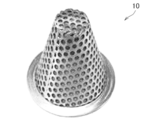
- FIG. 13 is a drawing substitute photograph showing another example of the heat transfer member (10) made of the porous material.
- This heat transfer member (10) is made by processing the same punching metal as in Example 1 into a conical shape.
- the heat transfer member (10) is arranged so that the bottom portion having a conical shape is in contact with the liquid material supply port (2c) on the inner bottom surface of the tank (2). Since a flange is provided on the outer periphery of the conical bottom of the heat transfer member (10), the heat from the tank heater (2a) passes through the bottom surface of the tank (2) to the heat transfer member (10). It is transmitted efficiently to.
- the liquid material flowing in from the liquid material supply port (2c) surely passes through the hole of the heat transfer member (10), the liquid material can receive heat more reliably from the heat transfer member (10). Further, since the heat transfer member (10) has a conical shape, the shape of the heat transfer member (10) can be made more compact than that of the heat transfer member (10) according to the first embodiment.
- the heat transfer member (10) can be made of foamed metal.
- a heat transfer member (10) can be made of, for example, a rectangular foam metal having a bottom surface and a top surface of 30 mm square and a height of 100 mm.
- the heat transfer member (10) included in the vaporizer (1b) according to the fourth embodiment is composed of a pipe-shaped member, and the internal space of the pipe-shaped member corresponds to the flow path (10a).
- the overall shape of the heat transfer member (10) made of a pipe-shaped member and the number and paths of the flow paths (10a) formed by the internal space of the pipe-shaped member are not particularly limited. From the viewpoint of making the shape of the heat transfer member (10) compact, it is preferable to form the heat transfer member (10) with, for example, a pipe-shaped member having a spiral shape or a zigzag shape.
- the shape of the cross section of the internal space of the pipe-shaped member corresponding to the flow path (10a) is also not particularly limited, and may be, for example, circular, semicircular, or other shapes.
- FIG. 14 is a schematic view showing an example of a heat transfer member (10) included in the vaporizer (1b) according to the fourth embodiment.
- Each of the heat transfer members (10) illustrated in FIGS. 14 (a) and 14 (b) is composed of one pipe-shaped member having a spiral shape and is arranged at the bottom of the tank (2). It is installed.
- One end (10b) of the flow path (10a) which is the internal space of the pipe-shaped member, is connected to the liquid material supply port (2c) of the tank (2). Further, the liquid material is supplied to the inside of the tank (2) from the other end (10c) of the flow path (10a).
- the heat supplied from the tank heater (2a) passes through the bottom of the tank (2) and one end (10b) of the flow path (10a) to the heat transfer member (10b). It is transferred to 10), and the heat is transferred to the liquid material flowing through the flow path (10a).
- the liquid material that flows inside the tank (2) due to convection can also receive heat from the surface of the heat transfer member (10).
- a gap may be present between the pipe-shaped members as in the heat transfer member (10) shown in FIG. 14 (b).
- the liquid material flowing inside the tank (2) can flow into the voids and receive heat from the surface of the heat transfer member (10).
- Example 5 is a modification of Example 4.
- a groove is formed in the metal plate constituting the bottom of the tank (2), and a flat plate is welded to the upper portion of the groove.
- the flow path (10a) is formed by closing the lid.
- the tank (2) since the bottom of the tank (2) also serves as the heat transfer member (10) provided with the flow path (10a), the tank (2) has a heat transfer member (10) as compared with the case where the heat transfer member (10) is separately provided. There is an advantage that it is not necessary to reduce the volume of the liquid material that can be stored.
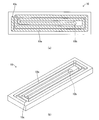
- FIG. 15 shows one example of the bottom of the tank (2) constituting the heat transfer member (10) included in the vaporizer (1b) according to the fifth embodiment of the present invention (a) top view and (b) perspective view. It is a figure.
- the bottom of the tank (2) illustrated in FIG. 19 is a stainless steel plate having a predetermined thickness, and a groove having a predetermined width and depth is cut in the plate, and another plate (not shown) is used.
- a heat transfer member (10) provided with a flow path (10a) can be formed by welding and covering the upper portion of the groove.
- one end (10b) of the groove as the flow path (10a) needs to also serve as the liquid material supply port (2c) of the tank (2) communicating with the liquid material charge pipe (9c), that end.
- the portion (10b) needs to be formed with a through hole connecting the bottom of the tank (2) from the inside to the outside.
- the plate material to be the lid of the groove is a tank (10a). It is necessary to form a through hole for communicating the inside of 2) with the end portion (10c).
- the heat transfer member (10) provided in the vaporizer (1b) according to the fifth embodiment having such a configuration, from the tank heater (2a) while the liquid material flows through the groove as the flow path (10a). The supplied heat is transferred to the liquid material via the bottom of the tank (2).
- the heat transfer member (10) functions as a medium for transferring the heat supplied from the tank heater (2a) to the liquid material, and efficiently transfers the liquid material stored in the tank (2). Can be heated.
- the present invention efficiently utilizes the heat of the heater having a limited installation area to ensure that the gas generated in the tank condenses in the flow path.
- a vaporizer having a smaller width in the left-right direction than the conventional one is realized.
- the heat transfer member becomes a new heat source by providing the heat transfer member inside the tank, and the heat supplied from the heater is used as a liquid material. It is possible to maintain a high level of gas generation efficiency by efficiently communicating to.
- the embodiment of the present invention is not limited to the embodiments and examples described here, and a part of the configuration can be modified and implemented without departing from the gist of the present invention.
- Vaporizer 1a Vaporizer (1st to 5th embodiments according to one aspect of the present invention) 1b: Vaporizer (sixth to eleventh embodiments according to another aspect of the present invention) 2: Tank 2a: Tank heater 2b: Extended surface 2c: Liquid material supply port 2d: Vaporized gas discharge port 3: Valve 3a: Gas supply valve 3b: Purge valve 3c: Charge valve 3d: Base member 4: Flow control means (mass flow) controller) 4a: Base part 5: Fixing member 5a: Fixing member heater 5b: Plate-shaped member 5b1: Flat part 5b2: Leg part 5c: Joint block 5d: Heat transfer block 5s: Space 6: Heat transfer plate 6a: Heat transfer plate heater 7 : Case 7a: Liquid pool 8: Sensor 8a: Liquid level sensor 8b: Temperature sensor 8c: Pressure sensor 8s: Stem 9: Piping 9a: Gas supply pipe 9b: Purge gas supply pipe 9c: Liquid material charge pipe 9
Landscapes
- Chemical & Material Sciences (AREA)
- Organic Chemistry (AREA)
- Chemical Kinetics & Catalysis (AREA)
- General Chemical & Material Sciences (AREA)
- Engineering & Computer Science (AREA)
- Materials Engineering (AREA)
- Mechanical Engineering (AREA)
- Metallurgy (AREA)
- Chemical Vapour Deposition (AREA)
- Feeding, Discharge, Calcimining, Fusing, And Gas-Generation Devices (AREA)
- Filling Or Discharging Of Gas Storage Vessels (AREA)
Abstract
液体材料を加熱してガスを発生させるタンク(2)と、発生したガスの供給を開始又は停止するガス供給バルブ(3a)と、ガス供給バルブ(3a)から流出したガスの流量を制御する流量制御手段(4)とを備えた気化器(1a)であって、ガス供給バルブ(3a)及び流量制御手段(4)は固定部材(5)に固定され、固定部材(5)のガス供給バルブ(3a)及び流量制御手段(4)と固定されていない側の面に固定部材ヒータ(5a)を備え、ガス供給バルブ(3a)及び流量制御手段(4)は1つ又は2つ以上の伝熱板(6)と接し、少なくとも1つの伝熱板(6)のガス供給バルブ(3a)及び流量制御手段(4)と接していない側の面に伝熱板ヒータ(6a)を備える。
Description
この発明は、気化器に関する。より具体的には、この発明は、主として半導体の製造装置及びフラットパネルディスプレイの製造装置等に組み込まれて使用される気化器に関する。
気化器は、常温において液相状態にある材料(以下、「液体材料」と称呼する。)を加熱してガスを発生させ、発生したガスを外部に供給する装置である。一般に、気化器は、液体材料を加熱してガスを発生させるタンクと、タンクにおいて発生したガスの供給の開始及び停止を行うバルブと、ガスの流量を制御する流量制御手段と、によって構成されている。気化器は、例えば半導体の製造装置及びフラットパネルディスプレイの製造装置等に半導体及び光ファイバーの原料となるガスを供給すること等を目的として、これらの製造装置等に組み込まれて使用される。
気化器のタンクにおいて発生したガスが通過する配管の温度が十分に高くないと、配管の内壁表面においてガスが凝結して液体に戻ることがある。これを防止するためには、配管を加熱して高い温度に保持することが有効である。例えば、特許文献1及び2には、流量制御手段の本体及び/又は機器取り付け面を有するマニホールドブロック等に設けられた穴又は溝にヒータを挿入して、ガスの流路を加熱することができる気化器の発明が記載されている。
また、例えば特許文献3には、タンクの外壁の内部に設けられた内部流路を使ってガスを外部に供給することができる気化器の発明が記載されている。これによれば、バルブユニットを設けるための配管をタンクとマスフローコントローラの間に設ける必要が無いため、配管におけるガスの液化を防ぎ且つ気化器をコンパクトに構成することができる。更に、特許文献4には、平板状のアルミニウム系材料にラバーヒータを貼り付けることによって構成されたヒータプレートを使用して導管を加熱することができる気化器の発明が記載されている。
上述したようにガスの流路の近くに穴又は溝を設けてヒータを挿入する従来技術及びタンクの外壁の内部に内部流路を設ける従来技術においては、構成部材を特殊な形状に加工する必要がある。このため、製造コストが増大したり構成部材の小型化が困難になったりするという課題がある。一方、上述したように平板状のアルミニウム系材料にラバーヒータを貼り付けることによって構成されたヒータプレートは単純且つコンパクトであり、上記のような課題は懸念されていなかった。
しかしながら、最近、半導体製造装置において、異なる種類の液体材料から発生するガスを供給する複数の気化器が左右に隣接して壁面に設置されることが多い。また、半導体製造装置自体の小型化が進んでいる。このため、気化器を正面から見た場合における左右方向の幅を小さくして、多数の気化器を並べて設置した場合においても全体の幅があまり大きくならならようにしたいという要求が従来にも増して高まっている。このような要求に応えるためにヒータプレートの幅を小さくすると、配管及びタンクに対して十分な熱量を与えることができなくなるという課題がある。
また、気化器の左右方向の幅を小さくしたり、気化器全体の大きさを小さくしたりすると、気化器が備えるタンクの大きさも必然的に小さくせざるを得ない。一般にタンク内の液体材料を加熱する手段としては、タンクの外側に設けられた平面状のラバーヒータ等が用いられる。タンクの大きさが小さくなると、ラバーヒータを貼ることができるタンクの表面積も小さくなるので、タンク内の液体材料に単位時間当たりに供給される熱量も従来に比べて少なくなる。そうすると、気化器が単位時間当たりに生成することができるガスの量が従来に比べて少なくなるので、半導体の製造効率が低下するという課題がある。
更に、タンクの大きさが小さくなると、タンクに蓄えることができる液体材料の容積も小さくなる。そうすると、気化器の運転に伴う液体材料の消費によりタンク内の液体材料がより短時間で欠乏するので、タンク内の液体材料の蓄積量を一定に保つためには、従来よりも頻繁に液体材料をタンク内に補給する必要が生ずる。しかしながら、一般的には、外部からタンク内に補給される液体材料は加熱されておらず、当該液体材料の温度はタンク内の液体材料の温度よりも低いため、新たな液体材料が供給されることによってタンク内の液体材料の温度が低下し、ガスの発生効率が更に低下するという課題がある。
本発明は、上記のような諸課題に鑑みてなされたものであり、簡単な構造を有し、容易に製造することができるヒータを用いて、幅を小さくした場合においてもガスが凝結して液体に戻ることを防ぐことができる気化器を提供することを1つの目的とする。更に、本発明は、従来に比べて大きさが小さいタンクを備えた気化器においても、従来の気化器と同等のガスの発生効率を維持することができる気化器を提供することをもう1つの目的とする。
1つの態様において、本発明に係る気化器(1a)は、液体材料を加熱してガスを発生させるタンク(2)と、発生したガスの供給を開始又は停止するガス供給バルブ(3a)と、ガス供給バルブ(3a)から流出するガスの流量を制御する流量制御手段(4)とを備える気化器(1a)であって、タンク(2)は液体材料を加熱する平面状のタンクヒータ(2a)を備え、ガス供給バルブ(3a)及び流量制御手段(4)は固定部材(5)に固定され、固定部材(5)はガス供給バルブ(3a)及び流量制御手段(4)と固定されない側の面に平面状の固定部材ヒータ(5a)を備え、ガス供給バルブ(3a)及び流量制御手段(4)は1つ又は2つ以上の伝熱板(6)と接し、伝熱板(6)のうちの少なくとも1つの伝熱板(6)はガス供給バルブ(3a)及び流量制御手段(4)と接していない側の面に平面状の伝熱板ヒータ(6a)を備える。
本発明に係る気化器(1a)は、少なくとも3箇所にヒータ(2a、5a、6a)を備え、簡単な構造を有しながら、しかも、幅を小さくした場合においても配管及びタンク(2)に対して十分な熱量を与えることができる。
更に、本発明に係る気化器(1a)は、上記構成に加え、タンク(2)を構成する面のうちの1つの面(2b)がガス供給バルブ(3a)及び流量制御手段(4)の方向に伸長しており、固定部材(5)の固定部材ヒータ(5a)が設けられている側が当該伸長した面(2b)に固定されていてもよい。この構成によれば、タンク(2)から固定部材(5)へと熱が伝わるので、配管がより均一に加熱される。
もう1つの態様において、本発明に係る気化器(1b)は、上記構成に加え、タンク(2)の内部に設けられ、タンクヒータ(2a)と熱伝導可能に構成され、且つ金属又は合金からなる、1つ又は2つ以上の伝熱部材(10)を更に備える。この構成によれば、タンクヒータ(2a)から供給された熱が伝熱部材(10)を介してタンク(2)内の液体材料に効率よく伝わる。
更に、本発明に係る気化器(1b)は、タンク(2)に液体材料を供給する配管である液体材料チャージ管(9c)が補助ヒータ(9h)を更に備える。この構成によれば、タンク(2)に新たに供給される液体材料を、補助ヒータ(9h)によって予め加熱することができる。
本発明によれば、簡単な構造を有する加熱手段によって配管内におけるガスの凝結を確実に防止することができる気化器を提供することができる。更に、従来と比べて左右方向の幅が小さく、従ってタンクの大きさが小さな気化器においても、タンクに蓄えられた液体材料を効率よく加熱して、ガスの発生効率を高い水準に維持することができる。
本発明を実施するための形態について、図面を使って以下に詳細に説明する。以下の説明及び図面は本発明を実施するための形態の例を示したものであり、本発明を実施するための形態は、以下の説明及び図面に示された形態に限定されない。
《第1実施形態》
図1は、本発明に係る気化器(1)の外観の例を示す斜視図である。気化器(1)は全体が直方体の形状をしたケース(7)に収納されている。ケース(7)は、正面から見たときの左右方向の幅が短く、上下方向の高さが長い形状をしている。突出部を除くケース(7)の外寸は、例えば、幅が50mm、奥行きが180mm、高さが600mmである。本発明に係る気化器(1)は、従来の気化器に比べて幅方向の寸法が小さいことが特徴である。このため、従来の気化器に比べて同じ設置幅において、より多くの台数の気化器(1)を並べて設置することができる。
図1は、本発明に係る気化器(1)の外観の例を示す斜視図である。気化器(1)は全体が直方体の形状をしたケース(7)に収納されている。ケース(7)は、正面から見たときの左右方向の幅が短く、上下方向の高さが長い形状をしている。突出部を除くケース(7)の外寸は、例えば、幅が50mm、奥行きが180mm、高さが600mmである。本発明に係る気化器(1)は、従来の気化器に比べて幅方向の寸法が小さいことが特徴である。このため、従来の気化器に比べて同じ設置幅において、より多くの台数の気化器(1)を並べて設置することができる。
気化器(1)の正面から見て奥側の面は壁面等に接して固定する面となっており、ケース(7)から上方向及び下方向に突出した固定用の部材を用いて壁面等に固定することができる。気化器(1)の上面には、例えば、ガスを外部に供給したりパージガスを内部に送り込んだりするためのガス配管の接続部及び気化器(1)の内部と電気信号をやり取りするためのコネクタ等が設けられる。
図2は、本発明の1つの実施の形態(以下、「第1実施形態」と称呼される場合がある。)に係る気化器(1a)の内部の構造の例を示す右側面図である。即ち、図1に示したケース(7)の右側面を構成するパネルを取り外して、第1実施形態に係る気化器(1a)の内部の構造が見える状態にしたものである。図2に例示するように、気化器(1a)は、液体材料を加熱してガスを発生させるタンク(2)と、発生したガスの供給を開始又は停止するガス供給バルブ(3a)と、ガス供給バルブ(3a)から流出するガスの流量を制御する流量制御手段(4)とを備える。
タンク(2)は、液体材料を貯蔵するための容器である。タンク(2)には、液体材料をチャージするための入口と、発生させたガスを放出するための出口が設けられる。液体材料をチャージするための当該入口からケース(7)の前面又は上面までの間に、液体材料をチャージするための配管である液体材料チャージ管(9c)を設けることができる。液体材料は、液体材料チャージ管(9c)を経由して、図示しない貯蔵手段からタンク(2)内にチャージすることができる。液体材料チャージ管(9c)の途中にはチャージバルブ(3c)を設けてもよい。
タンク(2)は、液体材料を貯蔵し、液体材料を加熱してガスを発生させることを目的とする構成要素であるので、高温においても液体材料に対する優れた耐腐食性を有する材料によって構成され、内圧の上昇にも耐える構造を有することが求められる。このため、タンク(2)は、例えば、5.0mmの厚さを有するステンレス鋼製の板材を溶接して組み立てることができる。タンク(2)の形状は、内容積を多く確保することができることから、ケース(7)の内部に収納することができる直方体の形状とすることが好ましい。
タンク(2)には、種々の目的に応じて様々なセンサ(8)を設けることができる。例えば、タンク(2)には、チャージされた液体材料の貯蔵量を知るために1つ又は2つ以上の液位センサ(8a)を設けることができる。その他に、タンク(2)には、液体材料の温度を測定する温度センサ(8b)及び/又はタンク(2)において発生したガスの圧力を測定する圧力センサ(8c)を設けてもよい。ケース(7)内のタンク(2)よりも低い位置には、万一タンク(2)から外部に液体材料が漏れた場合に備えて液溜り(7a)を設けることができる。
ガス供給バルブ(3a)は、タンク(2)において発生したガスの供給を開始又は停止するバルブである。ガス供給バルブ(3a)は、後述する流量制御手段(4)とタンク(2)との間に設けることができる。ガス供給バルブ(3a)としては、開いたときの流体抵抗が少なく且つガスを円滑に流すことが可能である限り、どのような形式のバルブを用いてもよい。ガス供給バルブ(3a)の開閉動作を行う手段としては、例えば圧縮空気とシリンダによるもの又は電動アクチュエータによるもの等、公知の手段を用いることができる。
流量制御手段(4)は、ガス供給バルブ(3a)から流出するガスの流量を制御するものである。流量制御手段(4)としては、公知のマスフローコントローラを用いることが好ましい。マスフローコントローラは、ガスの流量を測定する流量センサ、流量センサからの出力に基づいてガスの流量を制御する流量制御バルブ及びこれらを制御する制御回路等によって構成される。第1実施形態に係る気化器(1a)に用いるマスフローコントローラ(4)は、例えば120℃に昇温されたガスの流量を制御することができるように構成されたものであることが好ましい。
図3は、第1実施形に係る気化器(1a)の配管の例を示す模式図である。図3は、タンク(2)及びその周辺の配管の接続状態を模式的に示したものであり、配管の実際の位置や方向を示すものではない。上述したように、タンク(2)には、液体材料をチャージするための入口と、発生させたガスを放出するための出口が設けられる。タンク(2)の入口と外部とを接続する配管である液体材料チャージ管(9c)の途中にはチャージバルブ(3c)が設けられる。液体材料は、液体材料チャージ管(9c)を通ってタンク(2)の内部に貯蔵される。液面の撹乱を防ぐ観点からは、タンク(2)の入口はタンク(2)の底部に設けることが好ましい。
タンク(2)の出口と外部とを接続する配管であるガス供給管(9a)の途中には、上述したように、ガス供給バルブ(3a)が設けられ、ガス供給バルブ(3a)と外部との間には流量制御手段(4)が設けられる。タンク(2)において発生したガスは、ガス供給バルブ(3a)及び流量制御手段(4)を通って気化器(1a)の外部に導かれ、半導体製造装置等に供給される。
図3に示す例においては、ガス供給バルブ(3a)と流量制御手段(4)との間に、パージガス用の配管であるパージガス供給管(9b)との接続部がある。パージガス供給管(9b)は、この接続部と外部との間に設けられる。パージガス供給管(9b)の途中にはパージバルブ(3b)が設けられる。気化器(1a)から外部へのガスの供給を停止した後にガス供給バルブ(3a)を閉じてパージバルブ(3b)を開くことにより、流量制御手段(4)及びその周囲の配管内に残存するガスを不活性ガス等のパージガスによって置換することができる。ガス供給バルブ(3a)、パージバルブ(3b)及びチャージバルブ(3c)は、何れも液体材料及びガスに対する耐食性を有し且つ加熱による温度上昇に耐えるバルブであることが好ましい。
再び図2を参照すると、第1実施形態において、タンク(2)は液体材料を加熱する平面状のタンクヒータ(2a)を備える。平面状のタンクヒータ(2a)は、タンク(2)を構成する容器の外壁に接して設けられ且つ容器を加熱することによってタンク(2)の内部にある液体材料を間接的に加熱することが可能である限り、どのようなヒータであってもよい。平面状のタンクヒータ(2a)は、ヒータの設置容積をあまり必要としないので好ましい。タンクヒータ(2a)としては、例えば1.5mmの厚さを有するラバーヒータを用いることができる。ラバーヒータは、耐熱性のゴムの間にワイヤ状又は箔状の抵抗発熱体を挟みこんだものである。一般的に、ラバーヒータの1平方センチメートル当たりの発熱量は最大で1ワット程度であり、耐熱温度は200℃程度である。
タンクヒータ(2a)は、タンク(2)の表面であって、液体材料の液面よりも下側の位置に設けることが好ましい。タンクヒータ(2a)は、例えばタンク(2)の底面又は側面に設けることができる。但し、タンクヒータ(2a)をタンク(2)の側面に設ける場合は、気化器(1a)の正面から見て左右方向の側面に設けると、その分タンク(2)の左右方向の幅を小さくしなければならずタンク(2)の容積も小さくなるので、前後方向の側面のみに設けることが好ましい。図2に例示した気化器(1a)の場合、タンクヒータ(2a)はタンク(2)の底面に設けられている。尚、上記説明においては平面状のタンクヒータ(2a)を例示したが、タンク(2)の内部に設けられ且つ液体材料を直接加熱することができる棒状のヒータをタンクヒータ(2a)として採用してもよい。
第1実施形態において、ガス供給バルブ(3a)及び流量制御手段(4)は固定部材(5)に固定され、固定部材(5)はガス供給バルブ(3a)及び流量制御手段(4)と固定されない側の面に平面状の固定部材ヒータ(5a)を備える。図4は、第1実施形態に係る気化器(1a)の固定部材(5)を含む部分の例を示す斜視図である。図4に例示するように、固定部材(5)は、板状部材(5b)と板状部材(5b)に固定された複数の継手ブロック(5c)とによって構成することができる。板状部材(5b)は、継手ブロック(5c)を介してガス供給バルブ(3a)及び流量制御手段(4)を載置することができる細長い板状の部材であって、その幅は正面から見たときの気化器(1a)の幅よりも小さい。
継手ブロック(5c)は、内部にガスの流路が形成された直方体の形状を有する部材である。継手ブロック(5c)の底面は板状部材(5b)にネジ等を使って固定される。継手ブロック(5c)の底面とは反対側の面はガス供給バルブ(3a)及び流量制御手段(4)の底部とガスの流路が一致するようにネジ等を使って固定される。これにより、ガス供給バルブ(3a)及び流量制御手段(4)のガスの流路は、これらの中間に配置された継手ブロック(5c)の流路によって接続される。尚、ガス供給バルブ(3a)は単独で、又はパージバルブ(3b)と共に、ベース部材(3d)に固定され、ベース部材(3d)を介して継手ブロック(5c)に固定することができる。同様に、流量制御手段(4)も、ベース部(4a)を介して継手ブロック(5c)に固定することができる。
図4に例示するガス供給バルブ(3a)、流量制御手段(4)及び固定部材(5)が互いに組み合わさった部分は「集積化ガス供給システム」と称呼される場合がある。集積化ガス供給システムは、継手ブロック(5c)の採用により配管のサイズをコンパクトにすると共に接続を容易にして、多くの種類のガスを同時に取り扱うためのガスラインを従来よりも少ない面積に設置することができる。集積化ガス供給システムは、個々の構成部品として、或いはシステム全体を含むユニットとして流通しており、これらを利用することによって気化器の製造コストを削減することができる。
固定部材(5)は、図4に例示するように、ガス供給バルブ(3a)及び流量制御手段(4)と固定されない側の面に平面状の固定部材ヒータ(5a)を備える。換言すれば、固定部材(5)に含まれる板状部材(5b)のガス供給バルブ(3a)及び流量制御手段(4)とは反対側の面に平面状の固定部材ヒータ(5a)が配設される。これにより、固定部材(5)に含まれる複数の継手ブロック(5c)が加熱され、継手ブロック(5c)の内部に設けられたガスの流路並びにガス供給バルブ(3a)及び流量制御手段(4)の内部に設けられたガスの流路を流れるガスの凝結を防ぐことができる。
固定部材ヒータ(5a)は、固定部材(5)に含まれる板状部材(5b)に接して設けられ、継手ブロック(5c)の内部に設けられたガスの流路並びにガス供給バルブ(3a)及び流量制御手段(4)の内部に設けられたガスの流路を加熱することによってガスを間接的に加熱することが可能である限り、どのようなヒータであってもよい。平面状の固定部材ヒータ(5a)は、ヒータの設置容積をあまり必要としないので好ましい。固定部材ヒータ(5a)としては、タンクヒータ(2a)と同様に、例えば、1.5mmの厚さを有するラバーヒータを用いることができる。
タンク(2)の容器内において発生したガスは、容器内の液体材料の液面よりも上の空間に滞留し、その後、タンク(2)に設けられた出口から配管を経由してガス供給バルブ(3a)及び流量制御手段(4)を通って外部に供給される。従って、タンク(2)からの出口の配管は、タンク(2)の容器の上面側に設けることが好ましい。それに伴い、ガス供給バルブ(3a)及び流量制御手段(4)も、タンク(2)よりも上方に設けることが好ましい。
第1実施形態において、ガス供給バルブ(3a)及び流量制御手段(4)は1つ又は2つ以上の伝熱板(6)と接し、伝熱板(6)のうちの少なくとも1つの伝熱板(6)はガス供給バルブ(3a)及び流量制御手段(4)と接していない側の面に平面状の伝熱板ヒータ(6a)を備える。図5は、図4に例示した第1実施形態に係る気化器(1a)の固定部材(5)を含む部分を他の角度から見た斜視図である。図5に例示するように、ガス供給バルブ(3a)及び流量制御手段(4)は1つ又は2つ以上の伝熱板(6)と接する。即ち、ガス供給バルブ(3a)及び流量制御手段(4)と接する伝熱板(6)は1枚でもよいし、2枚以上であってもよい。図5の例では、2枚の伝熱板(6)が、ガス供給バルブ(3a)のベース部材(3d)及び流量制御手段(4)のベース部(4a)の部分を両側から挟むようにして設けられている。
伝熱板(6)は、後述する伝熱板ヒータ(6a)からの熱を伝え易いように、高い熱伝導性を有する材料によって構成することが好ましい。伝熱板(6)は、例えば、アルミニウム若しくは銅又はこれらの合金によって構成することができる。アルミニウム合金としては、例えば一般的な材料である5052材を用いることができる。伝熱板(6)の厚さは、例えば1.6mm以上であり且つ2.0mm以下であることが好ましい。伝熱板(6)の厚さを1.6mm以上とすることにより伝熱板(6)が有する熱容量が増えるので保温に有利である。伝熱板(6)の厚さを2.0mm以下とすることにより伝熱板(6)の加工が容易となる。
伝熱板(6)のうちの少なくとも1つの伝熱板(6)は、ガス供給バルブ(3a)及び流量制御手段(4)と接していない側の面に平面状の伝熱板ヒータ(6a)を備える。これにより、気化器(1a)の幅よりも小さい幅を有する固定部材ヒータ(5a)から供給される熱だけでは液体材料の加熱が不十分な場合においても、伝熱板ヒータ(6a)から供給される熱が補われることにより、流路におけるガスの凝結をより確実に防止することができる。
伝熱板ヒータ(6a)は、伝熱板(6)に接して設けられ、継手ブロック(5c)の内部に設けられたガスの流路並びにガス供給バルブ(3a)及び流量制御手段(4)の内部に設けられたガスの流路を加熱することによってガスを間接的に加熱することが可能である限り、どのようなヒータであってもよい。平面状の伝熱板ヒータ(6a)は、ヒータの設置容積をあまり必要としないので好ましい。伝熱板ヒータ(6a)としては、タンクヒータ(2a)や固定部材ヒータ(5a)と同様に、例えば、1.5mmの厚さを有するラバーヒータを用いることができる。
伝熱板ヒータ(6a)が設けられる位置は、伝熱板(6)のうちの少なくとも1つの伝熱板(6)のガス供給バルブ(3a)及び流量制御手段(4)と接していない側の面である。伝熱板ヒータ(6a)をガス供給バルブ(3a)及び/又は流量制御手段(4)に直接的に接して設けると、これらの部材を例えば検査及び/又は修理等を目的として取り外す作業が困難となる。伝熱板(6)のガス供給バルブ(3a)及び流量制御手段(4)と接していない側の面に伝熱板ヒータ(6a)を設ければ、伝熱板(6)を取り外すことにより伝熱板ヒータ(6a)も同時に外すことができるので、これらの部材の検査及び修理等が容易となる。
伝熱板ヒータ(6a)は、伝熱板(6)のうちの1つの伝熱板(6)に設けるだけでも、固定部材ヒータ(5a)と共に2方向からガスの流路を加熱することができるので、本発明の効果を達成することができる。伝熱板(6)が2枚あり且つ伝熱板ヒータ(6a)を設置する容積を確保できる場合は、2枚の伝熱板(6)の両方に伝熱板ヒータ(6a)を設けて、固定部材ヒータ(5a)と共に、3方向からガスの流路を加熱してもよい。
以上に説明したように、第1実施形態に係る気化器(1a)においては、タンクヒータ(2a)によって液体材料を加熱して発生させたガスを、固定部材ヒータ(5a)及び伝熱板ヒータ(6a)の少なくとも2方向から加熱することができる。従って、気化器の幅を小さくした場合においても、流路内のガスの凝結を防止しながら、ガスを安定的に供給することができる。
《第2実施形態》
本発明のもう1つの実施の形態(以下、「第2実施形態」と称呼される場合がある。)に係る気化器(1a)は、第1実施形態のガス供給バルブ(3a)と固定部材(5)との間の空間及び流量制御手段(4)と固定部材(5)との間の空間の少なくとも一方に伝熱ブロック(5d)が設けられている気化器(1a)である。図4に示された本発明に係る気化器(1a)の固定部材(5)を含む部分を再び参照すると、図4に例示されるように、ガス供給バルブ(3a)と固定部材(5)との間及び流量制御手段(4)と固定部材(5)との間に空間が存在する場合がある。
本発明のもう1つの実施の形態(以下、「第2実施形態」と称呼される場合がある。)に係る気化器(1a)は、第1実施形態のガス供給バルブ(3a)と固定部材(5)との間の空間及び流量制御手段(4)と固定部材(5)との間の空間の少なくとも一方に伝熱ブロック(5d)が設けられている気化器(1a)である。図4に示された本発明に係る気化器(1a)の固定部材(5)を含む部分を再び参照すると、図4に例示されるように、ガス供給バルブ(3a)と固定部材(5)との間及び流量制御手段(4)と固定部材(5)との間に空間が存在する場合がある。
これらの空間は、ガス供給バルブ(3a)及び流量制御手段(4)を複数の継手ブロック(5c)を介して板状部材(5b)に固定するために生ずるものである。このような空間があると、空気の層は熱を伝え難いため、固定部材ヒータ(5a)及び伝熱板ヒータ(6a)からの熱がガス供給バルブ(3a)及び流量制御手段(4)に伝わり難い部分ができてしまう。そこで、第2実施形態に係る気化器(1a)においては、これらの空間の少なくとも一方に伝熱ブロック(5d)を設けることによって、当該部分の熱伝導を改善し、固定部材ヒータ(5a)及び図5に示したような伝熱板ヒータ(6a)から供給される熱がガス供給バルブ(3a)及び流量制御手段(4)に効率良く伝わるようにすることができる。
伝熱ブロック(5d)は、上述した伝熱板(6)と同様に、高い熱伝導性を有する材料によって構成することが好ましい。ガス供給バルブ(3a)と固定部材(5)との間の空間及び流量制御手段(4)と固定部材(5)との間の空間の少なくとも一方に伝熱ブロック(5d)を設けることにより、当該部分の熱伝導が改善されるので、本発明の効果を達成することができる。これらの両方の空間に伝熱ブロック(5d)を設ければ、全ての空間の熱伝導が改善されるので、より好ましい。伝熱ブロック(5d)の形状は、上記空間に隙間なく入れることができる形状及び寸法であることが好ましい。
《第3実施形態》
更に、本発明のもう1つの実施の形態(以下、「第3実施形態」と称呼される場合がある。)に係る気化器(1a)は、第1実施形態又は第2実施形態のタンク(2)を構成する面のうちの1つの面(2b)がガス供給バルブ(3a)及び流量制御手段(4)の方向に伸長しており、固定部材(5)の固定部材ヒータ(5a)が設けられている側が当該伸長した面(2b)に固定されている気化器(1a)である。図6は、第3実施形態に係る気化器(1a)のタンクの例を示す斜視図である。図6に例示するタンク(2)の容器の部分は6枚の板によって構成されており、そのうちの1つの面(2b)がタンク(2)の容器の部分から図の上方に向かって更に伸長している。伸長した面(2b)は、タンク(2)の容器の部分から上端までが継ぎ目のない1枚の板材によって構成されている。尚、図6においては、タンク(2)の内部の構造を示すため、タンク(2)の容器の部分を構成する6枚の板のうち図面に向かって手前側の1枚の板が省略されている。
更に、本発明のもう1つの実施の形態(以下、「第3実施形態」と称呼される場合がある。)に係る気化器(1a)は、第1実施形態又は第2実施形態のタンク(2)を構成する面のうちの1つの面(2b)がガス供給バルブ(3a)及び流量制御手段(4)の方向に伸長しており、固定部材(5)の固定部材ヒータ(5a)が設けられている側が当該伸長した面(2b)に固定されている気化器(1a)である。図6は、第3実施形態に係る気化器(1a)のタンクの例を示す斜視図である。図6に例示するタンク(2)の容器の部分は6枚の板によって構成されており、そのうちの1つの面(2b)がタンク(2)の容器の部分から図の上方に向かって更に伸長している。伸長した面(2b)は、タンク(2)の容器の部分から上端までが継ぎ目のない1枚の板材によって構成されている。尚、図6においては、タンク(2)の内部の構造を示すため、タンク(2)の容器の部分を構成する6枚の板のうち図面に向かって手前側の1枚の板が省略されている。
第3実施形態に係る気化器(1a)においては、固定部材(5)の固定部材ヒータ(5a)が設けられている側が、伸長した面(2b)に固定されている。つまり、図6に例示するタンク(2)の伸長した面(2b)に、図5に例示する固定部材(5)の固定部材ヒータ(5a)が設けられている側が固定されている。このように固定部材(5)を固定した結果、タンク(2)の伸長した面(2b)が固定部材(5)に固定されたガス供給バルブ(3a)及び流量制御手段(4)の方向に伸長することになる。上述したように、ガス供給バルブ(3a)及び流量制御手段(4)は、タンク(2)よりも上方に設けることが好ましいので、タンク(2)の伸長した面(2b)は、図6に例示するように、タンク(2)の容器の部分から図の上方に向かって更に伸長していることが好ましい。また、伸長した面(2b)のタンク(2)の容器を構成する部分とそれ以外の部分とが同じ厚さを有していることが好ましい。
また、上記のように固定部材(5)を固定した結果、タンク(2)の伸長した面(2b)と固定部材ヒータ(5a)とが互いに対向する位置に固定される。その結果、固定部材ヒータ(5a)とケース(7)との間にタンク(2)の伸長した面(2b)が存在することとなる。伸長した面(2b)は、タンク(2)の容器の部分から上端までが継ぎ目のない1枚の板材によって構成されている。このため、タンクヒータ(2a)によって暖められた液体材料の熱がタンク(2)を構成する部材の全体に伝わり、固定部材(5)が固定されている部分である伸長した面(2b)も暖められる。伸長した面(2b)が暖められることによって固定部材ヒータ(5a)において発生した熱がケース(7)の方向に逃げることが妨げられる。その結果、固定部材ヒータ(5a)において発生した熱が固定部材(5)の側に効率良く伝わり、ガス供給バルブ(3a)及び流量制御手段(4)の流路におけるガスの凝結をより確実に防ぐことができる。また、固定部材(5)を伸長した面(2b)に直接固定することによって固定部材(5)とタンク(2)とが強固に固定されるので、気化器(1a)全体の機械的な強度が高まる。
《第4実施形態》
更に、本発明のもう1つの実施の形態(以下、「第4実施形態」と称呼される場合がある。)に係る気化器(1a)は、第3実施形態の伸長した面(2b)と固定部材ヒータ(5a)との間に空間が存在する気化器(1a)である。図7は、図4に例示した本発明に係る気化器(1a)の固定部材(5)を構成する板状部材(5b)のみを描いた斜視図である。図4及び図7に例示するように、継手ブロック(5c)を介してガス供給バルブ(3a)及び流量制御手段(4)を固定する平面部(5b1)と、平面部(5b1)と伸長した面(2b)との間に空間が生ずるように平面部(5b1)の両端に設けられた脚部(5b2)とによって板状部材(5b)を構成することができる。
更に、本発明のもう1つの実施の形態(以下、「第4実施形態」と称呼される場合がある。)に係る気化器(1a)は、第3実施形態の伸長した面(2b)と固定部材ヒータ(5a)との間に空間が存在する気化器(1a)である。図7は、図4に例示した本発明に係る気化器(1a)の固定部材(5)を構成する板状部材(5b)のみを描いた斜視図である。図4及び図7に例示するように、継手ブロック(5c)を介してガス供給バルブ(3a)及び流量制御手段(4)を固定する平面部(5b1)と、平面部(5b1)と伸長した面(2b)との間に空間が生ずるように平面部(5b1)の両端に設けられた脚部(5b2)とによって板状部材(5b)を構成することができる。
上記のような構成において、脚部の高さ(平面部に直交する方向における寸法H)が十分に大きければ、固定部材ヒータ(5a)を設けた状態においても、図8に示すように、伸長した面(2b)と固定部材ヒータ(5a)との間に空間(5s)が生ずる(斜線部を参照)。空間(5s)は熱を伝え難いので、空間(5s)の存在により固定部材ヒータ(5a)の表面からタンク(2)の伸長した面(2b)に向かって熱が逃げることが更に妨げられる。
《第5実施形態》
更に、本発明のもう1つの実施の形態(以下、「第5実施形態」と称呼される場合がある。)に係る気化器(1a)は、第1実施形態乃至第4実施形態の何れかの実施形態のタンク(2)が1つ又は2つ以上の液位センサ(8a)を備え、液位センサ(8a)が取り付けられたステム(8s)の一方の端部がタンク(2)の内部の上面側に固定されており、ステム(8s)の他方の端部がタンク(2)の内部の下面側とは接していない気化器(1a)である。再び図6を参照すると、液位センサ(8a)は、ステム(8s)に沿って上下に動くことができるように取り付けられた略円筒形状のフロートによって構成することができる。液位センサ(8a)のフロートは、液体材料の液面の変動に伴って上下に移動し、フロートの内部に設けられた永久磁石から発生する磁界によってステム(8s)の内部に設けられたリードスイッチが作動する。これによって、液面の位置に対応する電気信号を発生させることができる。また、ステム(8s)の底部にはストッパーが設けられており、フロートの脱落を防止する。
更に、本発明のもう1つの実施の形態(以下、「第5実施形態」と称呼される場合がある。)に係る気化器(1a)は、第1実施形態乃至第4実施形態の何れかの実施形態のタンク(2)が1つ又は2つ以上の液位センサ(8a)を備え、液位センサ(8a)が取り付けられたステム(8s)の一方の端部がタンク(2)の内部の上面側に固定されており、ステム(8s)の他方の端部がタンク(2)の内部の下面側とは接していない気化器(1a)である。再び図6を参照すると、液位センサ(8a)は、ステム(8s)に沿って上下に動くことができるように取り付けられた略円筒形状のフロートによって構成することができる。液位センサ(8a)のフロートは、液体材料の液面の変動に伴って上下に移動し、フロートの内部に設けられた永久磁石から発生する磁界によってステム(8s)の内部に設けられたリードスイッチが作動する。これによって、液面の位置に対応する電気信号を発生させることができる。また、ステム(8s)の底部にはストッパーが設けられており、フロートの脱落を防止する。
上述したように、タンクヒータ(2a)は、例えばタンク(2)の底面に設けることができる。タンク(2)の底面にタンクヒータ(2a)を設けた場合、ステム(8s)の両端がタンク(2)の内部の上面側と下面側の双方に固定されていると、タンクヒータ(2a)の熱がステム(8s)を伝わってタンク(2)の下面側から上面側へと逃げ易くなる。第5実施形態に係る気化器(1a)においては、ステム(8s)の一方の端部がタンク(2)の内部の上面側に固定され、ステム(8s)の他方の端部はタンク(2)の内部の下面側とは接していない。従って、タンクヒータ(2a)の熱がステム(8s)を伝わってタンク(2)の下面側から上面側へと逃げることが妨げられるので、タンクヒータ(2a)から発生する熱をタンク(2)の内部に貯蔵された液体材料の加熱に無駄無く使用することができる。
《第6実施形態》
ところで、本明細書の冒頭において述べたように、気化器を正面から見た場合における左右方向の幅を小さくして、多数の気化器を並べて設置した場合においても全体の幅があまり大きくならないようにしたいという要求が高まっている。このような要求に応えるためには、気化器が備えるタンクも必然的に小さくせざるを得ない。そうなると、タンク内の液体材料を加熱する手段(例えば、ラバーヒータ等)も小型化せざるを得ず、タンク内の液体材料に単位時間当たりに供給される熱量も従来に比べて少なくなる。その結果、気化器が単位時間当たりに生成することができるガスの量が従来に比べて少なくなるので、半導体の製造効率が低下するという課題がある。
ところで、本明細書の冒頭において述べたように、気化器を正面から見た場合における左右方向の幅を小さくして、多数の気化器を並べて設置した場合においても全体の幅があまり大きくならないようにしたいという要求が高まっている。このような要求に応えるためには、気化器が備えるタンクも必然的に小さくせざるを得ない。そうなると、タンク内の液体材料を加熱する手段(例えば、ラバーヒータ等)も小型化せざるを得ず、タンク内の液体材料に単位時間当たりに供給される熱量も従来に比べて少なくなる。その結果、気化器が単位時間当たりに生成することができるガスの量が従来に比べて少なくなるので、半導体の製造効率が低下するという課題がある。
そこで、本発明の第6実施形態に係る気化器は、上述した第1実施形態乃至第5実施形態の何れかに係る気化器(1a)であって、タンク(2)の内部に設けられ、タンクヒータ(2a)と熱伝導可能に構成され、且つ金属又は合金からなる、1つ又は2つ以上の伝熱部材(10)を更に備える、気化器(1b)である。
第6実施形態に係る気化器(1b)の構成について以下に詳細に説明する。図9は、第6実施形態に係る気化器(1b)のタンク(2)及びその周辺部分の構成の例を示す右側面図である。図9においては、気化器(1b)及びタンク(2)の内部の構造を示すため、気化器(1b)のケースとタンク(2)の側壁とを取り外した状態が描かれている。気化器(1b)は、上述した第1実施形態乃至第5実施形態の何れかに係る気化器(1a)であって、タンク(2)の内部に設けられ、タンクヒータ(2a)と熱伝導可能に構成され、且つ金属又は合金からなる、1つ又は2つ以上の伝熱部材(10)を更に備える、気化器(1b)である。尚、図9においては、気化器(1b)を構成する他の部材との区別を容易にすることを目的として網目状のハッチングが伝熱部材(10)に施されているが、図9における図示及び以下の説明はあくまでも気化器(1b)の構成についての例示に過ぎず、伝熱部材(10)の具体的な構成は当該例示に限定されるものではない。
金属又は合金からなる伝熱部材(10)は、液体材料と比べて、より高い熱伝導率を有する。上記のように伝熱部材(10)はタンク(2)の内部に設けられ且つタンクヒータ(2a)と熱伝導可能に構成されている。従って、タンクヒータ(2a)において発生した熱が伝熱部材(10)に伝わり、伝熱部材(10)が新たな熱源となり、タンクヒータ(2a)から供給される熱をタンク(2)に蓄えられた液体材料に効率良く伝えることができる。これにより、伝熱部材(10)を備えない従来技術に係る気化器と比べて、より高い効率にて液体材料を加熱することができるので、ガスの発生効率を高い水準に維持することができる。
タンク(2)の内部に設けられる伝熱部材(10)の総数は、1つでもよく或いは2つ以上であってもよい。タンク(2)の内部に複数の伝熱部材(10)を設ける場合、伝熱部材(10)の形状は同一であってもよく或いは互いに異なる形状であってもよい。伝熱部材(10)を構成する金属又は合金としては、例えばステンレス鋼のような液体材料によって腐食され難い優れた耐食性を有する金属又は合金を採用することが好ましい。1つの伝熱部材(10)を構成する材料は1種類の金属又は合金であってもよく或いは複数種の金属又は合金の組み合わせであってもよい。
タンク(2)の内部に設けられる伝熱部材(10)は、少なくとも一部がタンク(2)に蓄えられた液体材料の液面よりも低い位置に設けられることが好ましく、伝熱部材(10)の全体が液面よりも低い位置に設けられることがより好ましい。但し、第6実施形態に係る気化器(1b)において、液体材料が消費されることによって液面が下方に移動して伝熱部材(10)の一部又は全体が一時的に液面よりも高い位置になることは許容される。
タンクヒータ(2a)において発生した熱が伝熱部材(10)に伝わる経路は、特に限定されない。例えば、タンクヒータ(2a)がタンク(2)の底部の外壁に設けられており且つ伝熱部材(10)がタンク(2)の底部の内壁に接して設けられている場合は、タンクヒータ(2a)によって供給される熱がタンク(2)の底部を経由して伝熱部材(10)に伝わる。この場合、タンク(2)の底部の内壁と伝熱部材(10)との接触部の面積を大きくすれば、熱がより伝わり易くなるので好ましい。伝熱部材(10)は、タンク(2)のタンクヒータ(2a)が設けられていない面の内壁に接して設けられていてもよい。この場合、タンクヒータ(2a)において発生した熱がタンク(2)の底部及び/又は液体材料を経由して伝熱部材(10)に伝わる。即ち、何れの場合においても、伝熱部材(10)はタンクヒータ(2a)と熱伝導可能に構成される。
或いは、伝熱部材(10)は、タンク(2)の内壁から離れた位置に設けられていてもよい。この場合、タンクヒータ(2a)によって供給される熱が液体材料を経由して伝熱部材(10)に伝わる。即ち、この場合においても、伝熱部材(10)はタンクヒータ(2a)と熱伝導可能に構成される。上述した何れの場合においても、金属又は合金からなる伝熱部材(10)は液体材料及び気化ガスよりも高い熱伝導率を有するので、タンクヒータ(2a)によって供給される熱が常に伝熱部材(10)に優先的に伝わる。その結果、伝熱部材(10)が新たな熱源となって、伝熱部材(10)の周囲の液体材料に効率的に熱を伝達し、液体材料を加熱することができる。
次に、第6実施形態に係る気化器(1b)の使用方法について説明する。気化器(1b)の配管は、図3に例示した気化器(1a)の配管と同様の構成を有するので、以下の説明については図3を参照されたい。第6実施形態に係る気化器(1b)においても、タンク(2)に接続される配管として、ガス供給管(9a)、パージガス供給管(9b)及び液体材料チャージ管(9c)の3つの配管を設けることができる。液体材料チャージ管(9c)は、タンク(2)の液体材料供給口(2c)に外部から液体材料を供給する配管である。液体材料チャージ管(9c)には、液体材料の供給を開始又は停止することができるチャージバルブ(3c)を設けることができる。気化器(1b)を使用する際は、液体材料が貯蔵された外部の貯蔵手段(図示せず)に液体材料チャージ管(9c)の入り口側を接続しておく。タンク(2)に蓄えられた液体材料の量を液位センサ(8a)等によって検知し、液体材料が欠乏したらチャージバルブ(3c)を開いて貯蔵手段に貯蔵された液体材料をタンク(2)に補充する。液体材料の補充が完了したらチャージバルブ(3c)を閉じる。
ガス供給管(9a)は、気化器(1b)において発生したガスを外部に取り出して利用するための配管である。ガス供給管(9a)にはガスの放出を開始又は停止することができるガス供給バルブ(3a)を設けることができる。また、単位時間当たりのガスの放出量を制御することができる流量制御手段(4)としてのマスフローコントローラを設けることができる。気化器(1b)を使用する際は、ガス供給バルブ(3a)及び流量制御手段(4)を操作して、必要なときに必要な量のガスを取り出すことができる。ガスが冷却されて液体に戻ることを防止することを目的として、ガス供給管(9a)に加熱手段を設けることができる。
パージガス供給管(9b)は、ガス供給管(9a)の内部に残留したガスを外部に排出することを目的として、不活性ガス等のパージガスを供給する配管である。パージガス供給管(9b)にはパージガスの放出を開始又は停止することができるパージバルブ(3b)を設けることができる。但し、第6実施形態に係る気化器(1b)において、パージガス供給管(9b)は必須の構成要素ではない。
次に、第6実施形態に係る気化器(1b)の具体的な構成例について説明する。図10は、第6実施形態に係る気化器(1b)の内部構造の例を示す右側面図である。図10においては、気化器(1b)及びタンク(2)の内部の構造を示すため、気化器(1b)のケース(7)の一部とタンク(2)の側壁とを取り外した状態が示されている。図10に例示した気化器(1b)においては、図9及び図3を参照しながら上述した気化器(1b)の各構成部材及び配管がケース(7)の中にコンパクトに収納されている。気化器(1b)は、気化ガス放出口(2d)から放出された気化ガスの圧力を測定する圧力センサ(8c)を備えることができる。
第6実施形態に係る気化器(1b)もまた、図1に例示した気化器(1a)と同様の外観を有することができる。即ち、気化器(1b)もまた、幅方向に多数の気化器を並べて設置するのに適している。また、気化器(1b)においては、幅方向の寸法が小さいにもかかわらず、伝熱部材(10)の作用により、従来技術に係る気化器と比べて、タンク(2)に蓄えられた液体材料を効率よく加熱して、ガスの発生効率を高い水準に維持することができる。
《第7実施形態》
次に、本発明の第7実施形態に係る気化器(1b)の構成について以下に詳細に説明する。第7実施形態に係る気化器(1b)は、上述した第6実施形態に係る気化器(1b)であって、伝熱部材(10)が、液体材料の流路(10a)を備える、気化器(1b)である。
次に、本発明の第7実施形態に係る気化器(1b)の構成について以下に詳細に説明する。第7実施形態に係る気化器(1b)は、上述した第6実施形態に係る気化器(1b)であって、伝熱部材(10)が、液体材料の流路(10a)を備える、気化器(1b)である。
ここで、「伝熱部材(10)が、液体材料の流路(10a)を備える」とは、伝熱部材(10)の内部に、液体材料が流動することができる経路が設けられていることを意味する。上述したように、タンク(2)の内部においては、液体材料供給口(2c)から液体材料が随時補充され、液体材料の液面からはガスが放出されるという物質の流れが形成される。少なくとも一部が液体材料と接している伝熱部材(10)が流路(10a)を備えると、液体材料は伝熱部材(10)の外表面に沿って流れるだけでなく、流路(10a)の内部にも流れることができる。これにより、伝熱部材(10)から液体材料への熱の伝達効率をより向上させることができる。
伝熱部材(10)が備える流路(10a)の形態は、液体材料が流動することが可能である限り、特に限定されない。例えば、流路(10a)は、連続する1本の穴であってもよく、或いは2本以上の穴が並列に設けられていてもよい。また、複数の流路が複雑に分岐又は合流して設けられていてもよい。気化器(1b)が複数の伝熱部材(10)を備える場合、個々の伝熱部材(10)の流路(10a)は同一の形態を有していてもよく、或いは異なる形態を有していてもよい。
《第8実施形態》
次に、本発明の第8実施形態に係る気化器(1b)の構成について以下に詳細に説明する。第8実施形態に係る気化器(1b)は、上述した第7実施形態に係る気化器(1b)であって、伝熱部材(10)の少なくとも一部が多孔質材料によって構成されており、当該多孔質材料が備える孔によって流路(10a)の少なくとも一部が構成されている、気化器(1b)である。
次に、本発明の第8実施形態に係る気化器(1b)の構成について以下に詳細に説明する。第8実施形態に係る気化器(1b)は、上述した第7実施形態に係る気化器(1b)であって、伝熱部材(10)の少なくとも一部が多孔質材料によって構成されており、当該多孔質材料が備える孔によって流路(10a)の少なくとも一部が構成されている、気化器(1b)である。
ここで、「多孔質材料が備える孔によって流路(10a)の少なくとも一部が構成されている」とは、伝熱部材(10)の少なくとも一部が多孔質材料によって構成されており、当該多孔質材料が備える孔が上述した流路(10a)としての機能を果たしていることを意味する。この場合、多孔質材料が備える孔は、液体材料が流動することができるように少なくともその一部が連続していることが好ましい。
多孔質材料はバルク体と比べて単位体積当たりの表面積が大きい。このため、伝熱部材(10)の少なくとも一部が多孔質材料によって構成されることにより、伝熱部材(10)から液体材料へと高い効率で熱を伝達することができる。また、多孔質材料の表面は液体材料が気化したガスの気泡が大きく成長することを妨げる効果がある。このため、液体材料の突沸を防止し、気化器(1b)から発生するガスの圧力を安定させることができる。尚、多孔質材料が有するこれらの効果は、液体材料の流路(10a)として機能する部分だけでなく、伝熱部材(10)の表面であって流路(10a)に該当しない部分においても同様に発揮させることができる。
尚、伝熱部材(10)の少なくとも一部を構成する多孔質材料は、多数の孔を備えた形状を有する金属又は合金であって且つそれらの孔を通って液体材料が流動することが可能である限り、どのような材料であってもよい。多孔質材料としては、例えば、数ミリメートルの直径を有する多数の孔が形成された金属板であるパンチングメタルであってもよく或いは金属又は合金からなる線材が網目状に編まれてなる部材であってもよい。また、多孔質材料は、ガスによって形成された気泡状の小さな孔を多量に有する「発泡金属」と呼ばれる材料であってもよい。この場合、気泡状の孔の少なくとも一部は互いに連続していることが好ましい。
《第9実施形態》
次に、本発明の第9実施形態に係る気化器(1b)の構成について以下に詳細に説明する。第9実施形態に係る気化器(1b)は、上述した第7実施形態又は第8実施形態に係る気化器(1b)であって、タンク(2)への液体材料の供給口である液体材料供給口(2c)からタンク(2)に流入した液体材料の少なくとも一部が流路(10a)の内部に流れることが可能であるように、少なくとも1つの伝熱部材(10)が設けられている、気化器(1b)である。
次に、本発明の第9実施形態に係る気化器(1b)の構成について以下に詳細に説明する。第9実施形態に係る気化器(1b)は、上述した第7実施形態又は第8実施形態に係る気化器(1b)であって、タンク(2)への液体材料の供給口である液体材料供給口(2c)からタンク(2)に流入した液体材料の少なくとも一部が流路(10a)の内部に流れることが可能であるように、少なくとも1つの伝熱部材(10)が設けられている、気化器(1b)である。
上述したように、タンク(2)の液体材料供給口(2c)からは、液体材料チャージ管(9c)から新たに供給される液体材料が流入する。従って、タンク(2)に流入した液体材料の少なくとも一部が流路(10a)の内部に流れることが可能であるように少なくとも1つの伝熱部材(10)を配置することにより、液体材料をより効率的に加熱することができる。
上記要件を満足する限り、伝熱部材(10)の具体的な配置は特に限定されない。例えば、少なくとも1つの伝熱部材(10)を液体材料供給口(2c)の近傍に配置してもよい。或いは、少なくとも1つの伝熱部材(10)を必ずしも液体材料供給口(2c)の近傍に配置する必要は無い。例えば、液体材料供給口(2c)から離れた位置であっても、液体材料供給口(2c)からタンク(2)へと流入した液体材料が所定の流速以上で流動する範囲内に少なくとも1つの伝熱部材(10)を配置してもよい。何れの場合においても、当該伝熱部材(10)の流路(10a)の入り口が、液体材料供給口(2c)からタンク(2)へと流入した液体材料が流動してくる方向に向けて設けられていることが好ましい。
《第10実施形態》
次に、本発明の第10実施形態に係る気化器(1b)の構成について以下に詳細に説明する。第10実施形態に係る気化器(1b)は、上述した第6実施形態乃至第9実施形態の何れかに係る気化器(1b)であって、伝熱面積比(Sr/(St+Sr))の値が0.1以上であり且つ0.5以下である、気化器(1b)である。ここで、伝熱面積比(Sr/(St+Sr))は、第1面積(Sr)と第2面積(St)との和(St+Sr)に対する第1面積(Sr)の比である。また、第1面積(Sr)は伝熱部材(10)の液体材料と接触する部分の面積の合計値であり、第2面積(St)はタンク(2)の液体材料と接触する部分の面積の合計値である。
次に、本発明の第10実施形態に係る気化器(1b)の構成について以下に詳細に説明する。第10実施形態に係る気化器(1b)は、上述した第6実施形態乃至第9実施形態の何れかに係る気化器(1b)であって、伝熱面積比(Sr/(St+Sr))の値が0.1以上であり且つ0.5以下である、気化器(1b)である。ここで、伝熱面積比(Sr/(St+Sr))は、第1面積(Sr)と第2面積(St)との和(St+Sr)に対する第1面積(Sr)の比である。また、第1面積(Sr)は伝熱部材(10)の液体材料と接触する部分の面積の合計値であり、第2面積(St)はタンク(2)の液体材料と接触する部分の面積の合計値である。
換言すれば、伝熱面積比(Sr/(St+Sr))の値は、液体材料と接触する部分におけるタンク(2)及び伝熱部材(10)の面積の合計に占める伝熱部材(10)のみの面積の比率である。従って、伝熱面積比(Sr/(St+Sr))の値は、タンクヒータ(2a)から液体材料に与えられる熱のうち伝熱部材(10)を経由して与えられる熱の比率の目安となる数値である。伝熱部材(10)を備えない従来技術に係る気化器においては、伝熱面積比(Sr/(St+Sr))の値は0(ゼロ)である。伝熱面積比(Sr/(St+Sr))の値が0.1以上であれば、本発明による液体材料の加熱効率の向上効果が達成される。また、伝熱面積比(Sr/(St+Sr))の値が0.5以下であれば、タンク(2)の内部に設置される伝熱部材(10)の体積が過剰になって液体材料を蓄えられる量が低減することを防止できる。伝熱面積比(Sr/(St+Sr))の値のより好ましい範囲は0.2以上であり且つ0.4以下である。
《第11実施形態》
次に、本発明の第11実施形態に係る気化器(1b)の構成について以下に詳細に説明する。前述したように、気化器の左右方向の幅を小さくしたり、気化器全体の大きさを小さくしたりすると、気化器が備えるタンクの大きさも必然的に小さくせざるを得ない。タンクの大きさが小さくなると、タンクに蓄えることができる液体材料の容積も小さくなる。そうすると、気化器の運転に伴う液体材料の消費によりタンク内の液体材料がより短時間で欠乏するので、タンク内の液体材料の蓄積量を一定に保つためには、従来よりも頻繁に液体材料をタンク内に補給する必要がある。しかしながら、一般的には、外部からタンク内に補給される液体材料は加熱されておらず、当該液体材料の温度はタンク内の液体材料の温度よりも低いため、新たな液体材料が供給されることによってタンク内の液体材料の温度が低下し、ガスの発生効率が更に低下するという課題がある。
次に、本発明の第11実施形態に係る気化器(1b)の構成について以下に詳細に説明する。前述したように、気化器の左右方向の幅を小さくしたり、気化器全体の大きさを小さくしたりすると、気化器が備えるタンクの大きさも必然的に小さくせざるを得ない。タンクの大きさが小さくなると、タンクに蓄えることができる液体材料の容積も小さくなる。そうすると、気化器の運転に伴う液体材料の消費によりタンク内の液体材料がより短時間で欠乏するので、タンク内の液体材料の蓄積量を一定に保つためには、従来よりも頻繁に液体材料をタンク内に補給する必要がある。しかしながら、一般的には、外部からタンク内に補給される液体材料は加熱されておらず、当該液体材料の温度はタンク内の液体材料の温度よりも低いため、新たな液体材料が供給されることによってタンク内の液体材料の温度が低下し、ガスの発生効率が更に低下するという課題がある。
そこで、第11実施形態に係る気化器(1b)は、上述した第6実施形態乃至第10実施形態の何れかに係る気化器(1b)であって、タンク(2)に液体材料を供給する配管である液体材料チャージ管(9c)が補助ヒータ(9h)を更に備える、気化器(1b)である。
図11は、第11実施形態に係る気化器(1b)のタンク(2)及びその周辺部分の構成の例を示す右側面図である。図5においては、気化器(1b)及びタンク(2)の内部の構造を示すため、気化器(1b)のケースとタンク(2)の側壁とを取り外した状態を示している。第11実施形態において、気化器(1b)は、第6実施形態の構成に加えて、タンク(2)に液体材料を供給する配管である液体材料チャージ管(9c)が補助ヒータ(9h)を更に備える。この構成によれば、図示しない外部の貯蔵手段から液体材料チャージ管(9c)を通ってタンク(2)の液体材料供給口(2c)に導かれる液体材料を予め加熱することができる。このため、タンク(2)の容積が小さく、液体材料を頻繁に補充しなければならない場合においても、タンク(2)の内部の液体材料を高い温度に維持することができ、ガスの発生効率を高い水準に維持することができる。
補助ヒータ(9h)は、液体材料チャージ管(9c)の全長に亘って設けてもよく或いは液体材料チャージ管(9c)の一部のみに設けてもよい。液体材料チャージ管(9c)の一部のみに補助ヒータ(9h)を設ける場合、液体材料の加熱効率を高める観点からは、できるだけタンク(2)に近い位置に補助ヒータ(9h)を設けることが好ましい。この場合、補助ヒータ(9h)から供給される熱は、液体材料チャージ管(9c)の内部を流れる液体材料を加熱するだけでなく、タンク(2)の液体材料供給口(2c)の周囲にも熱を供給することができるので、本発明における伝熱部材(10)による作用が一層強化される。
本発明の第7実施形態に係る気化器(1b)が備える伝熱部材(10)の幾つかの実施例につき、必要に応じて図面を参照しながら以下に詳しく説明する。
〈実施例1〉
図12は、多孔質材料によって構成された伝熱部材(10)の1つ例を示す図面代用写真である。この伝熱部材(10)は、数ミリメートルの直径を有する多数の貫通孔が形成されたステンレス鋼製の板材であるパンチングメタルを曲げ加工することによって円筒状に成形したものである。この円筒状のパンチングメタルの内側には、ステンレス鋼製の金網が更に配設されている。パンチングメタルと金網とは互いに接触するようにして組み立てられており、全体として茶漉し(ストレーナ)のような形状を有する。
図12は、多孔質材料によって構成された伝熱部材(10)の1つ例を示す図面代用写真である。この伝熱部材(10)は、数ミリメートルの直径を有する多数の貫通孔が形成されたステンレス鋼製の板材であるパンチングメタルを曲げ加工することによって円筒状に成形したものである。この円筒状のパンチングメタルの内側には、ステンレス鋼製の金網が更に配設されている。パンチングメタルと金網とは互いに接触するようにして組み立てられており、全体として茶漉し(ストレーナ)のような形状を有する。
この伝熱部材(10)は、円筒状の形状の中心軸がタンク(2)の底面に対して垂直に立つように配置される。従って、この伝熱部材(10)は、円筒状のパンチングメタルの外径がタンク(2)の内底面の最も短い寸法よりも小さく且つ円筒状のパンチングメタルの高さがタンク(2)の内部空間の高さよりも低いように構成されている。この伝熱部材(10)は、タンク(2)の内部に1つだけ設けてもよく或いは2つ以上設けてもよい。
液体材料は、タンク(2)の内部に設けられたこの伝熱部材(10)の孔を出入りする際に伝熱部材(10)から熱を受け取る。また、円筒状のパンチングメタルの内側に金網が配設されているので、この金網の網目を出入りする際に液体材料は金網からも熱を受け取ることができる。即ち、パンチングメタルに形成された孔及び金網の網目は伝熱部材(10)が備える流路(10a)に該当する。また、伝熱部材(10)の孔及び網目を出入りしない液体材料についても、例えば対流によってタンク(2)の内部において流動する際に、パンチングメタル及び金網の表面から液体材料が熱を受け取ることができる。
〈実施例2〉
図13は、多孔質材料によって構成された伝熱部材(10)のもう1つの例を示す図面代用写真である。この伝熱部材(10)は、実施例1と同様のパンチングメタルを円錐状に加工したものである。この伝熱部材(10)は、タンク(2)の内底面の液体材料供給口(2c)の周囲に円錐状の形状の底部が接するように配置される。この伝熱部材(10)の円錐状の形状の底部の外周にはフランジが設けられているので、タンクヒータ(2a)からの熱がタンク(2)の底面を介して伝熱部材(10)へと効率良く伝わる。また、液体材料供給口(2c)から流入した液体材料が伝熱部材(10)の孔を確実に通過するので、伝熱部材(10)から液体材料がより確実に熱を受け取ることができる。更に、この伝熱部材(10)は円錐形の形状を有するので、実施例1に係る伝熱部材(10)に比べて、伝熱部材(10)の形状をよりコンパクトにすることができる。
図13は、多孔質材料によって構成された伝熱部材(10)のもう1つの例を示す図面代用写真である。この伝熱部材(10)は、実施例1と同様のパンチングメタルを円錐状に加工したものである。この伝熱部材(10)は、タンク(2)の内底面の液体材料供給口(2c)の周囲に円錐状の形状の底部が接するように配置される。この伝熱部材(10)の円錐状の形状の底部の外周にはフランジが設けられているので、タンクヒータ(2a)からの熱がタンク(2)の底面を介して伝熱部材(10)へと効率良く伝わる。また、液体材料供給口(2c)から流入した液体材料が伝熱部材(10)の孔を確実に通過するので、伝熱部材(10)から液体材料がより確実に熱を受け取ることができる。更に、この伝熱部材(10)は円錐形の形状を有するので、実施例1に係る伝熱部材(10)に比べて、伝熱部材(10)の形状をよりコンパクトにすることができる。
〈実施例3〉
前述したように、伝熱部材(10)を発泡金属によって構成することができる。このような伝熱部材(10)は、例えば30ミリメートル四方の底面及び頂面並びに100ミリメートルの高さを有する直方形の発泡金属によって構成することができる。タンク(2)の内底面の液体材料供給口(2c)を覆うように当該伝熱部材(10)を配設することにより、液体材料供給口(2c)から流入した液体材料が発泡金属の内部に形成された微細な流路(10a)を通ってタンク(2)の内部空間へと流入するので、伝熱部材(10)から液体材料がより確実に熱を受け取ることができる。また、発泡金属の流路(10a)を構成する孔は小さいので、流路(10a)の内壁面の面積の伝熱部材(10)の体積に対する比率を大きくすることができる。
前述したように、伝熱部材(10)を発泡金属によって構成することができる。このような伝熱部材(10)は、例えば30ミリメートル四方の底面及び頂面並びに100ミリメートルの高さを有する直方形の発泡金属によって構成することができる。タンク(2)の内底面の液体材料供給口(2c)を覆うように当該伝熱部材(10)を配設することにより、液体材料供給口(2c)から流入した液体材料が発泡金属の内部に形成された微細な流路(10a)を通ってタンク(2)の内部空間へと流入するので、伝熱部材(10)から液体材料がより確実に熱を受け取ることができる。また、発泡金属の流路(10a)を構成する孔は小さいので、流路(10a)の内壁面の面積の伝熱部材(10)の体積に対する比率を大きくすることができる。
〈実施例4〉
実施例4に係る気化器(1b)が備える伝熱部材(10)は、パイプ状の部材によって構成されており、このパイプ状の部材の内部空間が流路(10a)に該当する。パイプ状の部材からなる伝熱部材(10)の全体としての形状並びにパイプ状の部材の内部空間によって構成される流路(10a)の本数及び経路は特に限定されない。伝熱部材(10)の形状をコンパクトにする観点からは、例えば渦巻状又はつづら折り状の形状を有するパイプ状の部材によって伝熱部材(10)を構成することが好ましい。流路(10a)に該当するパイプ状の部材の内部空間の横断面の形状も特に限定されず、例えば円形であってもよく或いは半円形又はその他の形状であってもよい。
実施例4に係る気化器(1b)が備える伝熱部材(10)は、パイプ状の部材によって構成されており、このパイプ状の部材の内部空間が流路(10a)に該当する。パイプ状の部材からなる伝熱部材(10)の全体としての形状並びにパイプ状の部材の内部空間によって構成される流路(10a)の本数及び経路は特に限定されない。伝熱部材(10)の形状をコンパクトにする観点からは、例えば渦巻状又はつづら折り状の形状を有するパイプ状の部材によって伝熱部材(10)を構成することが好ましい。流路(10a)に該当するパイプ状の部材の内部空間の横断面の形状も特に限定されず、例えば円形であってもよく或いは半円形又はその他の形状であってもよい。
図14は、実施例4に係る気化器(1b)が備える伝熱部材(10)の例を示す模式図である。図14の(a)及び(b)に例示する伝熱部材(10)は何れも、渦巻状の形状を有する1本のパイプ状の部材によって構成されており、タンク(2)の底部に配設されている。パイプ状の部材の内部空間である流路(10a)の一方の端部(10b)はタンク(2)の液体材料供給口(2c)に接続されている。また、流路(10a)の他方の端部(10c)からは、タンク(2)の内部へと液体材料が供給される。この伝熱部材(10)によれば、タンクヒータ(2a)から供給される熱がタンク(2)の底部及び流路(10a)の一方の端部(10b)を経由して伝熱部材(10)に伝わり、その熱が流路(10a)を流れる液体材料に伝わる。
尚、前述したように、例えば対流によってタンク(2)の内部において流動する液体材料も伝熱部材(10)の表面から熱を受け取ることができる。このような観点からは、図14の(b)に示す伝熱部材(10)のようにパイプ状の部材同士の間に空隙が存在するようにしてもよい。この場合、タンク(2)の内部において流動する液体材料が当該空隙に流れ込み、伝熱部材(10)の表面から熱を受け取ることができる。
〈実施例5〉
実施例5は実施例4の変形例である。実施例5に係る気化器(1b)が備える伝熱部材(10)においては、タンク(2)の底部を構成する金属板に溝が形成されており、当該溝の上部に平板を溶接する等して蓋をすることにより流路(10a)が形成されている。この構成においては、タンク(2)の底部が流路(10a)を備える伝熱部材(10)を兼ねているので、伝熱部材(10)を別途設ける場合に比べて、タンク(2)に蓄えることができる液体材料の容積を減少させずに済むというメリットがある。
実施例5は実施例4の変形例である。実施例5に係る気化器(1b)が備える伝熱部材(10)においては、タンク(2)の底部を構成する金属板に溝が形成されており、当該溝の上部に平板を溶接する等して蓋をすることにより流路(10a)が形成されている。この構成においては、タンク(2)の底部が流路(10a)を備える伝熱部材(10)を兼ねているので、伝熱部材(10)を別途設ける場合に比べて、タンク(2)に蓄えることができる液体材料の容積を減少させずに済むというメリットがある。
図15は、本発明の実施例5に係る気化器(1b)が備える伝熱部材(10)を構成するタンク(2)の底部の1つの例を示す(a)上面図及び(b)斜視図である。図19に例示するタンク(2)の底部は、所定の厚さを有するステンレス鋼製の板材であり、この板材に所定の幅及び深さを有する溝を切削し、図示しない別の板材を当該溝の上部に溶接して蓋をすることにより、流路(10a)を備える伝熱部材(10)を構成することができる。
但し、流路(10a)としての溝の一方の端部(10b)は液体材料チャージ管(9c)と連通するタンク(2)の液体材料供給口(2c)を兼ねる必要があるので、当該端部(10b)にはタンク(2)の底部の内側から外側へと繋がる貫通孔が形成される必要がある。一方、流路(10a)としての溝の他方の端部(10c)からはタンク(2)の内部へと液体材料が供給される必要があるので、当該溝の蓋となる板材にはタンク(2)の内部と当該端部(10c)とを連通させるための貫通孔が形成される必要がある。このような構成を有する実施例5に係る気化器(1b)が備える伝熱部材(10)によれば、流路(10a)としての溝を液体材料が流れる間に、タンクヒータ(2a)から供給される熱がタンク(2)の底部を経由して液体材料に伝わる。
上述した何れの実施例においても、伝熱部材(10)は、タンクヒータ(2a)から供給される熱を液体材料に伝える媒体として機能し、タンク(2)に蓄えられた液体材料を効率良く加熱することができる。
以上に説明したように、本発明は、何れの実施形態においても、設置面積の限られたヒータの熱を効率よく利用して、タンクにおいて発生したガスが流路内で凝結することを確実に防止することによって、従来よりも左右方向の幅を小さい気化器を実現するものである。また、気化器の小型化に伴ってタンクの容積を小さくした場合においても、タンクの内部に伝熱部材を設けることにより、伝熱部材が新たな熱源となり、ヒータから供給される熱を液体材料に効率良く伝えて、ガスの発生効率を高い水準に維持することができる。
本発明の実施の形態はここに説明した実施形態及び実施例に限られるものではなく、本発明の要旨を逸脱しない範囲においてその構成の一部を変更して実施することができる。
1:気化器
1a:気化器(本発明の1つの態様に係る第1実施形態乃至第5実施形態)
1b:気化器(本発明のもう1つの態様に係る第6実施形態乃至第11実施形態)
2:タンク
2a:タンクヒータ
2b:伸長した面
2c:液体材料供給口
2d:気化ガス放出口
3:バルブ
3a:ガス供給バルブ
3b:パージバルブ
3c:チャージバルブ
3d:ベース部材
4:流量制御手段(マスフローコントローラ)
4a:ベース部
5:固定部材
5a:固定部材ヒータ
5b:板状部材
5b1:平面部
5b2:脚部
5c:継手ブロック
5d:伝熱ブロック
5s:空間
6:伝熱板
6a:伝熱板ヒータ
7:ケース
7a:液溜り
8:センサ
8a:液位センサ
8b:温度センサ
8c:圧力センサ
8s:ステム
9:配管
9a:ガス供給管
9b:パージガス供給管
9c:液体材料チャージ管
9h:補助ヒータ
10:伝熱部材
10a:流路
10b:一方の端部
10c:他方の端部
Claims (11)
- 液体材料を加熱してガスを発生させるタンク(2)と、
発生したガスの供給を開始又は停止するガス供給バルブ(3a)と、
前記ガス供給バルブ(3a)から流出するガスの流量を制御する流量制御手段(4)と、を備える気化器(1a)であって、
前記タンク(2)は前記液体材料を加熱する平面状のタンクヒータ(2a)を備え、
前記ガス供給バルブ(3a)及び前記流量制御手段(4)は固定部材(5)に固定され、前記固定部材(5)は前記ガス供給バルブ(3a)及び前記流量制御手段(4)と固定されない側の面に平面状の固定部材ヒータ(5a)を備え、
前記ガス供給バルブ(3a)及び前記流量制御手段(4)は1つ又は2つ以上の伝熱板(6)と接し、前記伝熱板(6)のうちの少なくとも1つの伝熱板(6)は前記ガス供給バルブ(3a)及び前記流量制御手段(4)と接していない側の面に平面状の伝熱板ヒータ(6a)を備える、
気化器(1a)。 - 請求項1に記載された気化器(1a)であって、
前記ガス供給バルブ(3a)と前記固定部材(5)との間の空間及び前記流量制御手段(4)と前記固定部材(5)との間の空間の少なくとも一方に伝熱ブロック(5d)が設けられている、
気化器(1a)。 - 請求項1又は請求項2に記載された気化器(1a)であって、
前記タンク(2)を構成する面のうちの1つの面(2b)が前記ガス供給バルブ(3a)及び前記流量制御手段(4)の方向に伸長しており、前記固定部材(5)の固定部材ヒータ(5a)が設けられる側が当該伸長した面(2b)に固定されている、
気化器(1a)。 - 請求項3に記載された気化器(1a)において、
前記伸長した面(2b)と前記固定部材ヒータ(5a)との間に空間が存在する、
気化器(1a)。 - 請求項1乃至請求項4の何れか1項に記載された気化器(1a)であって、
前記タンク(2)が1つ又は2つ以上の液位センサ(8a)を備え、前記液位センサ(8a)が取り付けられたステム(8s)の一方の端部が前記タンク(2)の内部の上面側に固定されており、前記ステム(8s)の他方の端部が前記タンク(2)の内部の下面側とは接していない、
気化器(1a)。 - 請求項1乃至請求項5の何れか1項に記載された気化器(1a)であって、
前記タンク(2)の内部に設けられ、前記タンクヒータ(2a)と熱伝導可能に構成され、且つ金属又は合金からなる、1つ又は2つ以上の伝熱部材(10)を更に備える、
気化器(1b)。 - 請求項6に記載された気化器(1b)であって、
前記伝熱部材(10)が、前記液体材料の流路(10a)を備える、
気化器(1b)。 - 請求項7に記載された気化器(1b)であって、
前記伝熱部材(10)の少なくとも一部が多孔質材料によって構成されており、
前記多孔質材料が備える孔によって前記流路(10a)の少なくとも一部が構成されている、
気化器(1b)。 - 請求項7又は請求項8に記載された気化器(1b)であって、
前記タンク(2)への前記液体材料の供給口である液体材料供給口(2c)から前記タンク(2)に流入した前記液体材料の少なくとも一部が前記流路(10a)の内部に流れることが可能であるように、少なくとも1つの前記伝熱部材(10)が設けられている、
気化器(1b)。 - 請求項6乃至請求項9の何れか1項に記載された気化器(1b)において、
前記伝熱部材(10)の前記液体材料と接触する部分の面積の合計値である第1面積(Sr)と前記タンク(2)の前記液体材料と接触する部分の面積の合計値である第2面積(St)との和(St+Sr)に対する前記第1面積(Sr)の比である伝熱面積比(Sr/(St+Sr))の値が0.1以上であり且つ0.5以下である、
気化器(1b)。 - 請求項6乃至請求項10の何れか1項に記載された気化器(1b)であって、
前記タンク(2)に前記液体材料を供給する配管である液体材料チャージ管(9c)が補助ヒータ(9h)を更に備える、
気化器(1b)。
Priority Applications (1)
| Application Number | Priority Date | Filing Date | Title |
|---|---|---|---|
| JP2021508260A JP7533444B2 (ja) | 2019-03-27 | 2020-02-18 | 気化器 |
Applications Claiming Priority (4)
| Application Number | Priority Date | Filing Date | Title |
|---|---|---|---|
| JP2019060257 | 2019-03-27 | ||
| JP2019-060257 | 2019-03-27 | ||
| JP2019154345 | 2019-08-27 | ||
| JP2019-154345 | 2019-08-27 |
Publications (1)
| Publication Number | Publication Date |
|---|---|
| WO2020195349A1 true WO2020195349A1 (ja) | 2020-10-01 |
Family
ID=72609012
Family Applications (1)
| Application Number | Title | Priority Date | Filing Date |
|---|---|---|---|
| PCT/JP2020/006267 Ceased WO2020195349A1 (ja) | 2019-03-27 | 2020-02-18 | 気化器 |
Country Status (2)
| Country | Link |
|---|---|
| JP (1) | JP7533444B2 (ja) |
| WO (1) | WO2020195349A1 (ja) |
Cited By (2)
| Publication number | Priority date | Publication date | Assignee | Title |
|---|---|---|---|---|
| JP2021130853A (ja) * | 2020-02-20 | 2021-09-09 | 株式会社堀場エステック | 気化システム |
| KR20250048522A (ko) | 2023-10-02 | 2025-04-09 | 가부시키가이샤 호리바 에스텍 | 기화기 및 기화 시스템 |
Citations (4)
| Publication number | Priority date | Publication date | Assignee | Title |
|---|---|---|---|---|
| JPH0774113A (ja) * | 1993-09-02 | 1995-03-17 | Ckd Corp | ガス供給装置 |
| JP2009149939A (ja) * | 2007-12-20 | 2009-07-09 | Yamatake Corp | 液体材料ガスの供給方法及び液体材料ガス供給システム |
| JP2011518256A (ja) * | 2008-04-22 | 2011-06-23 | ピコサン オーワイ | 堆積反応炉のための装置および方法 |
| JP2014007289A (ja) * | 2012-06-25 | 2014-01-16 | Tokyo Electron Ltd | ガス供給装置及び成膜装置 |
-
2020
- 2020-02-18 WO PCT/JP2020/006267 patent/WO2020195349A1/ja not_active Ceased
- 2020-02-18 JP JP2021508260A patent/JP7533444B2/ja active Active
Patent Citations (4)
| Publication number | Priority date | Publication date | Assignee | Title |
|---|---|---|---|---|
| JPH0774113A (ja) * | 1993-09-02 | 1995-03-17 | Ckd Corp | ガス供給装置 |
| JP2009149939A (ja) * | 2007-12-20 | 2009-07-09 | Yamatake Corp | 液体材料ガスの供給方法及び液体材料ガス供給システム |
| JP2011518256A (ja) * | 2008-04-22 | 2011-06-23 | ピコサン オーワイ | 堆積反応炉のための装置および方法 |
| JP2014007289A (ja) * | 2012-06-25 | 2014-01-16 | Tokyo Electron Ltd | ガス供給装置及び成膜装置 |
Cited By (3)
| Publication number | Priority date | Publication date | Assignee | Title |
|---|---|---|---|---|
| JP2021130853A (ja) * | 2020-02-20 | 2021-09-09 | 株式会社堀場エステック | 気化システム |
| JP7457522B2 (ja) | 2020-02-20 | 2024-03-28 | 株式会社堀場エステック | 気化システム |
| KR20250048522A (ko) | 2023-10-02 | 2025-04-09 | 가부시키가이샤 호리바 에스텍 | 기화기 및 기화 시스템 |
Also Published As
| Publication number | Publication date |
|---|---|
| JP7533444B2 (ja) | 2024-08-14 |
| JPWO2020195349A1 (ja) | 2020-10-01 |
Similar Documents
| Publication | Publication Date | Title |
|---|---|---|
| JP5008207B2 (ja) | 改良型毛管力気化器 | |
| JP5583021B2 (ja) | 高圧ガス貯蔵装置用の加温システム | |
| JP7533444B2 (ja) | 気化器 | |
| CN110537281A (zh) | 包括水分离器和储水罐的介质管理板,以及燃料电池系统 | |
| KR102937537B1 (ko) | 기화 장치, 가스 공급 장치 및 가스 공급 장치 제어 방법 | |
| JP6180894B2 (ja) | 水素貯蔵装置 | |
| CN103974908B (zh) | 电解装置以及具备该电解装置的热泵热水器 | |
| KR101067789B1 (ko) | 고주파 유도가열 전기보일러용 가열통 어셈블리 및 이를 구비한 고주파 유도가열 전기보일러 | |
| JP4393687B2 (ja) | 熱交換器、気化器、および、この気化器を用いた気化システム | |
| JP2015097988A (ja) | 電気分解装置及びこれを備えた温度調節水供給機 | |
| CN117916864A (zh) | 气化器 | |
| KR20110123254A (ko) | 가스 공급장치 | |
| JP2009264646A (ja) | 液体加熱装置 | |
| JP2011137604A (ja) | 温水制御ユニット | |
| JP6712440B2 (ja) | 液体材料気化装置、液体材料気化システム | |
| JP5875024B2 (ja) | 過熱水蒸気発生装置及び過熱水蒸気発生方法 | |
| KR102768408B1 (ko) | 조습 가스 발생 장치 | |
| JP5061529B2 (ja) | 高圧水素貯蔵容器 | |
| KR101393165B1 (ko) | 이온 필터 내장형 냉각수 탱크 및 이를 구비하는 연료전지 시스템 | |
| KR200330032Y1 (ko) | 액화가스 기화장치 | |
| CN223042745U (zh) | 补液装置 | |
| JP2010223546A (ja) | 貯湯式給湯器 | |
| JP5967124B2 (ja) | ドレン回収装置 | |
| CN120176006B (zh) | 一种固态储氢罐及储氢方法 | |
| KR20130076171A (ko) | 온수탱크 |
Legal Events
| Date | Code | Title | Description |
|---|---|---|---|
| 121 | Ep: the epo has been informed by wipo that ep was designated in this application |
Ref document number: 20778041 Country of ref document: EP Kind code of ref document: A1 |
|
| ENP | Entry into the national phase |
Ref document number: 2021508260 Country of ref document: JP Kind code of ref document: A |
|
| NENP | Non-entry into the national phase |
Ref country code: DE |
|
| 122 | Ep: pct application non-entry in european phase |
Ref document number: 20778041 Country of ref document: EP Kind code of ref document: A1 |