WO2020195178A1 - 電子ペン - Google Patents
電子ペン Download PDFInfo
- Publication number
- WO2020195178A1 WO2020195178A1 PCT/JP2020/004070 JP2020004070W WO2020195178A1 WO 2020195178 A1 WO2020195178 A1 WO 2020195178A1 JP 2020004070 W JP2020004070 W JP 2020004070W WO 2020195178 A1 WO2020195178 A1 WO 2020195178A1
- Authority
- WO
- WIPO (PCT)
- Prior art keywords
- electronic pen
- housing
- core body
- core
- pen
- Prior art date
- Legal status (The legal status is an assumption and is not a legal conclusion. Google has not performed a legal analysis and makes no representation as to the accuracy of the status listed.)
- Ceased
Links
Images


Classifications
-
- G—PHYSICS
- G06—COMPUTING OR CALCULATING; COUNTING
- G06F—ELECTRIC DIGITAL DATA PROCESSING
- G06F3/00—Input arrangements for transferring data to be processed into a form capable of being handled by the computer; Output arrangements for transferring data from processing unit to output unit, e.g. interface arrangements
- G06F3/01—Input arrangements or combined input and output arrangements for interaction between user and computer
- G06F3/03—Arrangements for converting the position or the displacement of a member into a coded form
- G06F3/041—Digitisers, e.g. for touch screens or touch pads, characterised by the transducing means
- G06F3/046—Digitisers, e.g. for touch screens or touch pads, characterised by the transducing means by electromagnetic means
-
- G—PHYSICS
- G06—COMPUTING OR CALCULATING; COUNTING
- G06F—ELECTRIC DIGITAL DATA PROCESSING
- G06F3/00—Input arrangements for transferring data to be processed into a form capable of being handled by the computer; Output arrangements for transferring data from processing unit to output unit, e.g. interface arrangements
- G06F3/01—Input arrangements or combined input and output arrangements for interaction between user and computer
- G06F3/03—Arrangements for converting the position or the displacement of a member into a coded form
- G06F3/033—Pointing devices displaced or positioned by the user, e.g. mice, trackballs, pens or joysticks; Accessories therefor
- G06F3/0354—Pointing devices displaced or positioned by the user, e.g. mice, trackballs, pens or joysticks; Accessories therefor with detection of two-dimensional [2D] relative movements between the device, or an operating part thereof, and a plane or surface, e.g. 2D mice, trackballs, pens or pucks
- G06F3/03545—Pens or stylus
-
- B—PERFORMING OPERATIONS; TRANSPORTING
- B43—WRITING OR DRAWING IMPLEMENTS; BUREAU ACCESSORIES
- B43K—IMPLEMENTS FOR WRITING OR DRAWING
- B43K19/00—Non-propelling pencils; Styles; Crayons; Chalks
- B43K19/16—Making non-propelling pencils
- B43K19/18—Making pencil writing-cores
-
- B—PERFORMING OPERATIONS; TRANSPORTING
- B43—WRITING OR DRAWING IMPLEMENTS; BUREAU ACCESSORIES
- B43K—IMPLEMENTS FOR WRITING OR DRAWING
- B43K29/00—Combinations of writing implements with other articles
-
- B—PERFORMING OPERATIONS; TRANSPORTING
- B43—WRITING OR DRAWING IMPLEMENTS; BUREAU ACCESSORIES
- B43K—IMPLEMENTS FOR WRITING OR DRAWING
- B43K29/00—Combinations of writing implements with other articles
- B43K29/08—Combinations of writing implements with other articles with measuring, computing or indicating devices
-
- G—PHYSICS
- G06—COMPUTING OR CALCULATING; COUNTING
- G06F—ELECTRIC DIGITAL DATA PROCESSING
- G06F2203/00—Indexing scheme relating to G06F3/00 - G06F3/048
- G06F2203/041—Indexing scheme relating to G06F3/041 - G06F3/045
- G06F2203/04105—Pressure sensors for measuring the pressure or force exerted on the touch surface without providing the touch position
-
- G—PHYSICS
- G06—COMPUTING OR CALCULATING; COUNTING
- G06F—ELECTRIC DIGITAL DATA PROCESSING
- G06F3/00—Input arrangements for transferring data to be processed into a form capable of being handled by the computer; Output arrangements for transferring data from processing unit to output unit, e.g. interface arrangements
- G06F3/01—Input arrangements or combined input and output arrangements for interaction between user and computer
- G06F3/03—Arrangements for converting the position or the displacement of a member into a coded form
- G06F3/041—Digitisers, e.g. for touch screens or touch pads, characterised by the transducing means
- G06F3/044—Digitisers, e.g. for touch screens or touch pads, characterised by the transducing means by capacitive means
- G06F3/0442—Digitisers, e.g. for touch screens or touch pads, characterised by the transducing means by capacitive means using active external devices, e.g. active pens, for transmitting changes in electrical potential to be received by the digitiser
Definitions
- the present invention relates to an electronic pen that realizes a function as a position indicator for an electronic device equipped with a position detection device such as a tablet PC (Personal Computer), for example.
- a position detection device such as a tablet PC (Personal Computer), for example.
- electronic pens and tablet PCs have come to be used in the field of education as well.
- electronic pens and tablet PCs are lent to each child and student, and the stroke order of kanji is taught through the input of characters, and answers to questions are obtained.
- electronic pen it is convenient because the input can be repeated many times without using a paper medium.
- the electronic pen is relatively hard to break, for example, a core body made of POM resin is used.
- FIG. 3 is a diagram showing a conventional example of an electronic pen.
- the electronic pens 100 and 200 shown in FIGS. 3 (A) and 3 (B) have an electromagnetic induction method for displacement.
- a component in which the coils 104 and 204 are wound around the outer surfaces of the ferrite cores 103 and 203 is mounted inside the housings 101 and 201.
- Capacitors (not shown) are connected to the coils 104 and 204 to form a resonance circuit.
- the cores 102 and 202 are inserted through the through holes of the ferrite cores 103 and 203 through the openings of the housings 101 and 201, come into contact with the pressure detection units 105 and 205, and detect the pressure applied to the cores 102 and 202. Is possible.
- drawing input to a tablet PC with an electronic pen can be easily rewritten over and over again, but the display screen can be easily switched, and the display screen can be switched in an instant. Yes, you can erase the input information. Therefore, in order to retain the input information, it is necessary to perform an operation to store the input information in the built-in storage medium. Then, there is a demand that not only an electronic pen and a tablet PC but also a paper medium such as a notebook be used together for learning. Therefore, it is required that recording can be performed on a paper medium without changing the electronic pen, and that drawing input can be performed on a tablet PC as well.
- Patent Document 1 discloses an electronic pen incorporating a mechanical pencil unit.
- a writing function on a paper medium and an input function on a tablet PC can be provided. It is possible to realize an electronic pen that combines.
- necessary information can be recorded on a paper medium and saved, and the answer to the problem can be input to the tablet PC and answered immediately.
- the present invention provides an electronic pen having both a function of writing on a paper medium and a function of a position indicator for an electronic device and also having resistance to impact.
- a tubular housing with an opening at the end on the pen tip side In the part on the pen tip side inside the housing, a tubular member fixed to the housing and It is composed of a rod-shaped body made of a material containing a pigment, and is provided with a core body having a drawing portion which is inserted and attached to the tubular member through the opening of the housing and functions when pulled out from the housing.
- an electronic pen characterized in that the diameter of a portion of the core body inserted into the tubular member is larger than the difference between the outer diameter and the inner diameter of the tubular member.
- the tubular member since the tubular member is fixed to the housing at the portion on the pen tip side inside the housing, it does not rattle against an impact (force) from the outside. Protected from damage. Since the core body is made of a material containing a pigment into a rod-like body, it is possible to physically leave a handwriting on a paper medium or the like. That is, it is provided with both a writing function on a paper medium or the like and a function as a position indicator used for an electronic device.
- the diameter of the portion inserted into the tubular member of the core body is made larger than the thickness of the tubular member in the diameter direction. That is, the thickness of the tubular member can be made thinner, and the diameter of the core body itself can be increased accordingly.
- the core body is configured to be thicker and hard to break. As a result, the strength of the core body is ensured in addition to the tubular member. Further, since the core body is provided with a pull-out portion, not only can it be easily attached to the housing, but it can also be easily pulled out. That is, it is easily exchanged.
- the electronic pen (position indicator) and the position detection device include an electromagnetic induction method (EMR (ElectroMagneticResonance technology) method) and an active electrostatic coupling method (AES (Active Electrostatic) method).
- EMR ElectroMagneticResonance technology
- AES Active Electrostatic
- the position detection device includes a sensor unit in which a plurality of loop coils are arranged in each of the X-axis direction and the Y-axis direction. Then, a transmission period in which electric power is sequentially supplied to the plurality of loop coils of the sensor unit to generate a magnetic field and a reception period in which the supply of electric power is stopped and a magnetic field from the outside is received are alternately provided.
- the corresponding electronic pen is provided with a resonance circuit consisting of a coil and a capacitor, and a signal is generated by a current flowing through the coil in response to a magnetic field from the sensor unit, and the position including the pen pressure information in this signal. Send to the detection sensor. This is received by the position detection device during the reception period, and the position indicated by the electronic pen and the writing pressure are detected.
- the electronic pen transmits the signal from the oscillation circuit mounted on the electronic pen including the pen pressure information, and receives this by the position detection device to indicate the indicated position and the brush. Detect pressure.
- the electronic pen of the present invention can be used for both electromagnetic induction type and active electrostatic coupling type.
- EMR method electromagnetic induction method
- FIG. 1 is a diagram for explaining an embodiment of the electronic pen of the present invention.
- FIG. 1A is a cross-sectional view of a pen tip side portion shown by dividing the electronic pen of this embodiment into two in the axial direction and removing the front side portion.
- the core body 2 does not show a cross section but the whole.
- FIG. 1 (B) is an enlarged view of the core body 2
- FIG. 1 (C) is a cross-sectional view showing a more enlarged view of the pen tip side portion of FIG. 1 (A).
- the housing 1 of the electronic pen of this embodiment has a cylindrical shape.
- the pen tip side of the housing 1 has a tapered shape, and the tip portion thereof has an opening 1h.
- the core body 2 described later is inserted and removed through the opening 1h.
- a ferrite core 3 formed in a tubular shape is housed in a portion on the pen tip side inside the housing 1. The end portion of the ferrite core 3 on the pen tip side (front end side) is fixed to the housing 1.
- a tubular cushioning member 5 formed of an elastomer is provided, and a tubular cushioning member 5 is provided via the cushioning member 5.
- the end portion of the ferrite core 3 on the rear end side is fixed to the housing 1.
- the ferrite core 3 is fixed to the housing 1 at both ends of the front end side and the rear end side thereof.
- the cushioning member 5 is provided only on the rear end side of the ferrite core 3, but the cushioning member may also be provided on the front end side of the ferrite core 3.
- the ferrite core 3 is fixed to the housing 1 directly or via an inclusion such as a cushioning member so as not to move or rattle in the housing 1. Just do it.
- the cushioning member 5 can be formed of various elastic materials such as rubber, sponge, and felt.
- a coil 4 is wound on the outer surface of the ferrite core 3.
- a pen pressure detection unit 7 having a variable capacitance capacitor configuration, which will be described later, and a capacitor (not shown) mounted on the circuit board 9 are connected in parallel to the coil 4 to form a resonance circuit.
- a pressing member 6 for connecting the core body 2 and the pen pressure detecting unit 7 is provided on the rear end side of the cushioning member 5.
- the end portion of the pressing member 6 on the pen tip side is a recess in which the rear end side of the core body 2 fits, and the end portion on the opposite side of the pen tip side presses the pen pressure detecting portion 7. It is a convex part of.
- the core body 2 is formed in a columnar shape (rod-shaped body) by a material containing a pigment.
- Pigment means a powder used for coloring and insoluble in water or oil. Pigments include graphite (black), titanium (white), chrome vermilion (vermilion), chrome yellow (yellow), iron oxide (red) as inorganic pigments, and permanent red (red) as organic pigments. There are phthalocyanine green (green) and first yellow (yellow). In addition to this, there are various pigments. By mixing the pigment with a medium such as resin, clay, or wax, core bodies of various colors can be formed. Therefore, depending on the pigment used, the core body 2 capable of leaving the handwriting of the desired color on a paper medium or the like can be formed.
- graphite graphite, stone ink
- the core body 2 is formed by mixing this with a predetermined resin.
- the core body 2 can leave a black handwriting similar to that of a pencil on a paper medium or the like, and has little wear.
- the hardness of the core body 2 is also about the same as that of the core body formed of the POM resin of the conventional electronic pen. Therefore, even when the electronic pen to which the core body 2 is attached is used on the operation surface of the tablet PC, it does not cause any inconvenience such as scratching the operation surface. ..
- the ratio of graphite and resin constituting the core body 2 is 50:50.
- the resin is polyethylene.
- the core body 2 is composed of four parts: a pen tip portion 2a, a pull-out portion 2b, a main body portion 2c, and a hold portion 2d.
- the pen tip portion 2a is a tapered portion, and the tip thereof is rounded.
- the pull-out portion 2b is a recess (groove portion) provided between the pen tip portion 2a and the main body portion 2c.
- the main body portion 2c is a portion located between the pull-out portion 2b and the hold portion 2d.
- the hold portion 2d is a portion located on the rear end side of the main body portion 2c and having a diameter shorter than the diameter of the main body portion 2c.
- the pen pressure detecting unit 7 includes a holding member 71 that holds the convex portion of the pressing member, a first electrode 72, a spacer 73 formed in a ring shape, a dielectric 74 that is a circular plate-like body, and a first. It is composed of 2 electrodes 75.
- the second electrode 75 is provided in contact with one surface of the dielectric.
- the first electrode 72 is positioned away from the other surface of the dielectric 74 via the spacer 73 when no pressing force (load) is applied to the first electrode 72.
- the holding member 71 is made of an elastic material such as synthetic rubber, and the spacer 73 is made of a hard resin or the like.
- the core body 2 mounted in the housing 1 is movable in the axial direction.
- a writing pressure is applied to the pen tip portion 2a of the core body 2
- the core body 2 is pushed into the housing 1 according to the writing pressure, and the pressing member 6 responds to the pressure member 6 via the holding member 71.
- the electrode 72 of 1 is brought closer to the dielectric 74 side, and the first electrode is brought into contact with the dielectric 74. Therefore, the distance and contact area between the first electrode 72 and the dielectric 74 change according to the pressing force applied to the pen tip portion 2a, and the distance between the first electrode and the second electrode is changed accordingly. Capacitance changes.
- the writing pressure applied to the pen tip portion 2a of the core body 2 can be detected according to the change in capacitance between the first electrode 72 and the second electrode 75.
- the core body 2 is pushed back by the first electrode 72 and the holding member 71 to return to the original position.
- a substrate holding member 8 is provided in the subsequent stage of the second electrode of the pen pressure detecting unit 7, and the circuit board 9 is fitted and held in the recess of the substrate holding member.
- Various circuit components such as a control IC (Integrated Circuit) and a capacitor are mounted on the circuit board 9.
- the circuit board 9 is connected to both ends of the coil 4 and the transmission wires from the first electrode and the second electrode of the pen pressure detection unit 7.
- the writing pressure is detected by the function of the circuit unit mounted on the circuit board 9, and the signal including the information indicating the writing pressure is included as the phase change of the signal (magnetic field) generated in the coil 4 by the resonance action. It is possible to send it by including it in.
- the cushioning member 5 and the substrate holding member 8 described above are held by a tubular holding member 10 provided inside the housing 1.
- the ferrite core 3, the coil 4, the cushioning member 5, the pressing member 6, the writing pressure detecting unit 7, and the substrate holding member 8 are held in the housing 1.
- the rear end side of the circuit board 9 is fixed to the rear end portion of the housing 1.
- the circuit board 9 is also held in the housing 1. In this way, the electronic pen of this embodiment is configured.
- the diameter of the housing 1 is 9.0 mm as shown in FIG. 1 (A). Further, as shown in FIG. 1C, the inner diameter of the ferrite core 3 is 3.0 mm, and the outer diameter is 5.0 mm. The diameter of the opening 1h of the housing 1 is 2.95 mm. The diameter of the main body 2c of the core 2 is 2.85.
- the core body is made of a high-strength material such as POM resin, and both ends in the diameter direction of the ferrite core are maintained in order to maintain the strength of the ferrite core. The total thickness of is made to be larger than the diameter of the core.
- the diameter of the opening 101h of the housing 101 is larger than the diameter of the through hole 103h of the ferrite core 103 (inner diameter of the ferrite core 103). Is bigger.
- the opening 201h of the housing 201 is larger than the diameter of the through hole 203h of the ferrite core 203 (the inner diameter of the ferrite core 203). The diameter of is larger.
- the total thickness of both ends of the ferrite core 3 in the radial direction is 2.0 mm, and the diameter of the main body 2c of the core body 2 is 2.85 mm.
- the diameter of the core body 2 is made larger than the conventional one, and the thickness of the ferrite core 3 is made thinner than the conventional one. Therefore, in the case of the electronic pen of this embodiment, the diameter of the main body portion 2c of the core body 2 is set to be longer than the length obtained by subtracting the inner diameter from the outer diameter of the ferrite core 3.
- the strength of the core body 2 can be increased by increasing the diameter of the main body portion 2c of the core body 2.
- the thickness of the ferrite core 3 is considerably thinner than that of the conventional electronic pen.
- the ferrite core 3 is fixed to the housing 1. Therefore, the ferrite core 3 does not move or rattle in the housing 1.
- the diameter of the opening 1h of the housing 1 is smaller than the inner diameter of the ferrite core 3. Therefore, even when the electronic pen of this embodiment is used for writing, the position of the core 2 is restricted by the inner wall portion of the opening 1h of the housing 1, and the core 2 is the ferrite core 3. There is no contact.
- the electronic pen of this embodiment is dropped and a large load (force) is applied to the pen tip portion 2a of the core body 2 protruding from the housing 1 in the direction intersecting the axial direction.
- a large load force
- the position of the core body 2 is restricted by the inner wall portion of the opening 1h of the housing 1, and the core body 2 does not come into contact with the ferrite core 3. Therefore, in the case of the electronic pen of this embodiment, the ferrite core 3 does not come into contact with the core body 2 and be damaged, and the ferrite core 3 may move or rattle in the housing 1. Since there is no ferrite core 3, the ferrite core 3 is not damaged by an external impact.
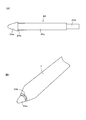
- FIG. 2 is a diagram for explaining another example of the core body of the electronic pen of the present invention.
- the core body 2A of the electronic pen of this example is formed in a columnar shape by a resin containing graphite like the core body 2 shown in FIG. 1, but its outer shape is the core body shown in FIG. Different from 2. That is, as shown in FIG. 2A, the core body 2A of this example is composed of four parts: a pen tip portion 2Aa, a pull-out portion 2Ab, a main body portion 2Ac, and a hold portion 2Ad.
- the pen tip 2Aa is a tapered part, and its tip is rounded.
- the pull-out portion 2Ab is a portion in which the main body portion 2Ac side of the pen tip portion 2Aa is a convex portion protruding outward.
- the main body portion 2Ac is a portion located between the pull-out portion 2Ab and the hold portion 2Ad.
- the hold portion 2Ad is a portion located on the rear end side of the main body portion 2Ac and having a diameter shorter than the diameter of the main body portion 2Ac.
- the core body 2A in which the pull-out portion 2Ab is configured as a convex portion in this way when this is attached to the housing 1, as shown in FIG. 2 (B), the end portion of the housing 1 and the core body 2A A gap is formed between the pull-out portion 2Ab and the pull-out portion 2Ab.
- the core body 2A mounted in the housing 1 the core body 2A is pulled out from the housing 1 by allowing the user to hook the fingernail of the hand or the like on the pull-out portion 2Ab and pull it out. It can be easily removed.
- the diameter of the core body can be made larger than the conventional one, it is possible to realize an electronic pen using a core body that is strong against impact.
- the thickness of the ferrite core 3 becomes thin, and the ferrite core 3 becomes vulnerable to impact.
- the cores 2 and 2A can be prevented from directly contacting the ferrite core 3.
- the ferrite core 3 is inside the housing 1. It can prevent rattling. With these configurations, it is possible to realize an electronic pen in which the thin ferrite core 3 is not damaged.
- the size of the diameter of the main body 2c of the core body 2 described with reference to FIG. 1 and the size of the inner diameter and outer diameter of the ferrite core 3 are examples, and may be various sizes depending on the size of the housing 1 and the like. Can be done.
- the diameter of the main body of the core 2 needs to be larger (longer) than the value (length) when the inner diameter is subtracted from the outer diameter of the ferrite core 3. That is, the diameter of the main body 2c of the core 2 is longer than the sum of the thicknesses of both ends in the radial direction of the ferrite core 3.
- the core body 2 that is thicker than the conventional electronic pen can be formed.
- the core bodies 2 and 2A have been described as being composed of a resin containing graphite.
- the graphite content by adjusting the graphite content, it is possible to construct an electronic pen having a different handwriting density when writing on a paper medium. That is, although there are pencils having different densities such as 2B, B, HB, F, H, and 2H, it is possible to realize an electronic pen having a different handwriting density.
- the type of resin containing graphite it is possible to adjust the density of the handwriting and change the writing taste.
- polyethylene is used as the resin
- polypropylene, polystyrene, polyamide and the like may be used as other examples.
- graphite and a predetermined clay can be mixed and fired to form a core body.
- the core body itself is worn down and shortened by writing on a paper medium or the like, so that the number of times the core body is replaced increases, so that the wear-out of resin or the like can be reduced. It is preferable to use.
- a core body capable of leaving handwriting of various colors can be constructed, and this can be used as the core body of the electronic pen.
- the present invention can be applied to an active electrostatic coupling type electronic pen. That is, the present invention can also be applied to realize an active electrostatic coupling type electronic pen having a writing function on a paper medium and a function as a position indicator for an electronic device.
- a coil may be mounted for charging.
- a ferrite core is arranged around the core body so as to prevent noise from being mixed into the core body.
- the present invention can be applied.
- a tubular member is used instead of a ferrite core to protect the core body or to move the core body in the axial direction. In some cases, it may be possible to move stably. The present invention can be applied even in such a case.
- the core body is made of a resin containing graphite and a conductive substance is further added, the conductive core body can be formed, so that an active electrostatic coupling type electronic pen can be realized. That is, in the case of an active electrostatic coupling type electronic pen, the core body used must have conductivity. Therefore, a core body having good conductivity can be formed by mixing graphite or the like and a material having conductivity with the core body, or by providing a metal shaft core in the core body.
Landscapes
- Engineering & Computer Science (AREA)
- Theoretical Computer Science (AREA)
- General Engineering & Computer Science (AREA)
- Physics & Mathematics (AREA)
- Human Computer Interaction (AREA)
- General Physics & Mathematics (AREA)
- Electromagnetism (AREA)
- Position Input By Displaying (AREA)
- Mechanical Pencils And Projecting And Retracting Systems Therefor, And Multi-System Writing Instruments (AREA)
Abstract
紙媒体等への筆記機能と電子機器への位置指示器としての機能との両方の機能を備え、衝撃に対する耐性をも備えた電子ペンを提供する。フェライトコア(3)は、筐体(1)の内部のペン先側の部分において、筐体(1)に対して固定される。芯体(2)は、グラファイトを含有する樹脂により棒状体に構成されている。芯体(2)は、筐体(1)の開口部(1h)を通じて、フェライトコア(3)に挿通されて取り付けられ、筐体(1)から引き抜く際に機能する引き抜き部(2b)を備えている。芯体(2)の本体部(2c)の直径は、フェライトコア(3)の直径方向の厚みよりも長くする。
Description
この発明は、例えば、タブレットPC(Personal Computer)などの位置検出装置が搭載された電子機器に対する位置指示器としての機能を実現する電子ペンに関する。
近年、教育分野においても、電子ペンとタブレットPCが活用されるようになってきている。例えば、児童、生徒の一人ひとりに電子ペンとタブレットPCを貸与し、文字の入力を通して漢字の書き順を教えたり、質問に対する解答を得るようにしたりするなどのことが行われている。電子ペンによるタブレットPCへの入力の場合、紙媒体を使用することなく、何度も繰り返し入力し直すことができるので便利である。電子ペンは、例えば、POM樹脂により形成された芯体が用いられるなど、比較的に壊れにくいものである。
図3は、電子ペンの従来例を示す図である。例えば、図3(A)、(B)に示す電子ペン100、200は、ずれも電磁誘導方式のものである。筐体101、201の内部には、フェライトコア103、203の外側面にコイル104、204が巻回された構成部分が搭載されている。コイル104、204には、図示しないコンデンサが接続されて共振回路を構成している。芯体102、202は、筐体101、201の開口部からフェライトコア103、203の貫通孔に挿通され、筆圧検出部105、205に当接し、芯体102、202にかけられる筆圧の検出が可能になっている。
そして、電子ペンによるタブレットPCへの描画入力は、紙媒体への筆記と異なり、何度も繰り返し書き直すことが簡単にできる反面、表示画面の切り替えが容易で、一瞬にして表示画面を切り替えることができ、入力情報を消去できる。従って、入力情報を保持しておくためには、入力情報を内蔵の記憶媒体に保存させるようにする操作を行わなければならない。そして、電子ペンとタブレットPCだけでなく、ノートなどの紙媒体も併用し、学習に利用するようにしたいとする要求がある。このため、電子ペンを持ち替えることなく、紙媒体に記録を行うことができると共に、タブレットPCに対しても描画入力を行えるようにすることが求められる。
後に記す特許文献1には、シャープペンシルユニットを組み込んだ電子ペンが開示されており、当該特許文献1に開示の発明を用いることによって、紙媒体への筆記機能とタブレットPCへの入力機能とを兼ね備えた電子ペンを実現することができる。当該電子ペンを利用することにより、必要な情報は紙媒体に記録して取っておくことができ、問題に対する解答などは、タブレットPCに入力して即座に解答するといったことが可能になる。
特許文献1に開示されたシャープペンシルユニットを組み込んだ電子ペンの場合、シャープペンシルの芯は、通常、0.5mm程度の細いものであり、また、電子ペン自体のペン先も細いものとなる。このため、小学校の低学年の児童が使用しようする場合にが、力の入れ加減が難しく、シャープペンシルの芯がすぐに折れてしまって、紙媒体に思ったように筆記できなかったり、タブレットPCの操作画面を傷付けてしまったりする可能性がある。
教育分野での利用を考えた場合、特に小学校の低学年の児童が使用することも考慮すると、図3を用いたように構成されている従来の電子ペンと同様にして使用できると共に、紙媒体への記録も可能な電子ペンの実現が望まれる。また、電子ペンを頻繁に落としたり、ぶつけたりするといったことも発生すると考えられる。このため、外から加わる衝撃に対しても耐性があり、壊れにくいことが要求される。
以上のことに鑑み、この発明は、紙媒体等への筆記機能と電子機器への位置指示器としての機能との両方の機能を備え、衝撃に対する耐性をも備えた電子ペンを提供する。
上記課題を解決するため、
ペン先側の端部に開口部を有する筒状の筐体と、
前記筐体の内部のペン先側の部分において、前記筐体に対して固定された筒状部材と、
顔料を含む素材によって棒状体に構成され、前記筐体の前記開口部を通じて、前記筒状部材に挿通されて取り付けられ、前記筐体から引き抜く際に機能する引き抜き部を有する芯体と
を備え、
前記芯体の前記筒状部材に挿通される部分の直径が、前記筒状部材の外径と内径の差よりも大きい
ことを特徴とする電子ペンを提供する。
ペン先側の端部に開口部を有する筒状の筐体と、
前記筐体の内部のペン先側の部分において、前記筐体に対して固定された筒状部材と、
顔料を含む素材によって棒状体に構成され、前記筐体の前記開口部を通じて、前記筒状部材に挿通されて取り付けられ、前記筐体から引き抜く際に機能する引き抜き部を有する芯体と
を備え、
前記芯体の前記筒状部材に挿通される部分の直径が、前記筒状部材の外径と内径の差よりも大きい
ことを特徴とする電子ペンを提供する。
この電子ペンによれば、筒状部材は、筐体の内部のペン先側の部分において、当該筐体に対して固定されるので、外からの衝撃(力)に対してがたつくことがなく、破損かから守られる。芯体は、顔料を含む素材によって棒状体に構成されているので、紙媒体等に対して物理的に筆跡を残すことができるようにされる。すなわち、紙媒体等への筆記機能と電子機器に対して用いられる位置指示器としての機能との両方を備えるようにされる。
更に、芯体の筒状部材に挿通される部分の直径は、筒状部材の直径方向の厚みよりも大きいものとされる。すなわち、筒状部材の厚みをより薄くすると共に、その分、芯体自体の直径を大きくすることができるようにされる。これにより、芯体をより太いものとして構成し、折れ難くされる。これにより、筒状部材に加えて、芯体の強度も確保される。また、芯体は、引き抜き部を備えているので、筐体に対して簡単に装着することができるだけでなく、簡単に引き抜くこともできようにされる。すなわち、交換容易に構成される。
以下、図を参照しながら、この発明の電子ペンの実施の形態について説明する。なお、電子ペン(位置指示器)及び位置検出装置の方式には、電磁誘導方式(EMR(Electro Magnetic Resonance technology)方式)とアクティブ静電結合方式(AES(Active Electrostatic)方式)とがある。
電磁誘導方式は、X軸方向とY軸方向とのそれぞれに複数のループコイルを配設したセンサ部を位置検出装置が備える。そして、当該センサ部の複数のループコイルに順次に電力を供給して磁界を発生させる送信期間と、電力の供給を停止し外部からの磁界を受信する受信期間とを交互に設ける。対応する電子ペンは、コイルとコンデンサとからなる共振回路を備え、当該センサ部からの磁界に応じて、当該コイルに電流が流れることにより信号を発生させ、この信号に筆圧情報を含めて位置検出センサに送信する。これを受信期間において位置検出装置が受信して、電子ペンによる指示位置と筆圧を検出する。
アクティブ静電結合方式の場合には、電子ペンは、電子ペンに搭載された発振回路からの信号に筆圧情報をも含めて送信し、これを位置検出装置で受信して、指示位置と筆圧を検出する。
この発明の電子ペンは、電磁誘導方式のものにも、また、アクティブ静電結合方式のものにも用いることができる。しかし、以下に説明する実施の形態においては、説明を簡単にするため、電磁誘導方式(EMR方式)の電子ペンに対して、この発明を適用した場合を例にして説明する。
[電子ペンの構成例]
図1は、この発明の電子ペンの実施の形態を説明するための図である。図1(A)は、この実施の形態の電子ペンを軸心方向に2分割し、前側部分を取り除いて示したペン先側部分の断面図である。但し、図1(A)において、芯体2は断面ではなく、その全体を示している。図1(B)は、芯体2を拡大して示した図であり、図1(C)は、図1(A)のペン先側部分をより拡大して示した断面図である。
図1は、この発明の電子ペンの実施の形態を説明するための図である。図1(A)は、この実施の形態の電子ペンを軸心方向に2分割し、前側部分を取り除いて示したペン先側部分の断面図である。但し、図1(A)において、芯体2は断面ではなく、その全体を示している。図1(B)は、芯体2を拡大して示した図であり、図1(C)は、図1(A)のペン先側部分をより拡大して示した断面図である。
図1(A)に示すように、この実施の形態の電子ペンの筐体1は、円筒形をなしている。図1(A)、(C)に示すように、筐体1のペン先側は、テーパー形状とされ、その先端部は開口部1hになっている。この開口部1hを介して、後述する芯体2が挿抜される。筐体1の内部のペン先側の部分には、筒状に形成されたフェライトコア3が収納される。フェライトコア3は、ペン先側(前端側)の端部部分が筐体1に対して固定される。また、フェライトコア3のペン先側とは反対側(後端側)には、例えば、エラストマ(elastomer)で形成された筒状の緩衝部材5が設けられており、この緩衝部材5を介して、フェライトコア3の後端側の端部部分が筐体1に対して固定される。
このように、フェライトコア3は、その前端側と後端側との両端部分において、筐体1に対して固定されている。なお、図1(A)においては、フェライトコア3の後端側にしか緩衝部材5を設けていないが、フェライトコア3の前端側にも緩衝部材を設けるようにしてもよい。要は、フェライトコア3は、直接に、あるいは、緩衝部材等の介在物を介して、筐体1に対して固定され、筐体1内で移動したり、がたついたりしないようにされていればよい。なお、緩衝部材5は、ゴム、スポンジ、フェルトなどの弾性のある種々の素材により形成できる。
図1(A)、(C)に示すように、フェライトコア3の外側面にはコイル4が巻回されている。コイル4には、後述する可変容量コンデンサの構成とされた筆圧検出部7や回路基板9に搭載されているコンデンサ(図示せず)が並列に接続されて、共振回路を構成する。緩衝部材5の後端側には、芯体2と筆圧検出部7とを接続する押圧部材6が設けられている。押圧部材6のペン先側の端部部分は、芯体2の後端側が嵌合する凹部になっており、ペン先側と反対側の端部部分は、筆圧検出部7を押圧するための凸部になっている。
芯体2は、顔料を含む素材によって円柱状(棒状体)に形成されたものである。顔料は、着色に用いる粉末で水や油に不溶のものを意味する。顔料には、無機顔料として、グラファイト(黒)、チタン(白)、クロムバーミリオン(朱)、黄鉛(黄)、酸化鉄(赤)などがあり、有機顔料として、パーマネントレッド(赤)、フタロシアニングリーン(緑)、ファーストイエロー(黄)などがある。この他にも種々の顔料が存在する。顔料と、樹脂、粘土、ワックスなどの媒体物とを混ぜ合わせることにより、種々の色の芯体を構成できる。したがって、用いる顔料によって、目的とする色の筆跡を紙媒体等に残すことができる芯体2を構成できる。
この実施の形態においては、顔料としてグラファイト(黒鉛、石墨)を用い、これを所定の樹脂と混ぜ合わせることによって芯体2を構成している。芯体2は、紙媒体等に対して鉛筆と同様の黒色の筆跡を残すことができると共に、擦り減りが少ないものである。また、芯体2は、その硬度も従来の電子ペンのPOM樹脂により形成された芯体と同程度とされる。従って、芯体2が装着された電子ペンがタブレットPCの操作面上で用いられた場合であっても、当該操作面に対して傷を付けることなどの不都合を生じさせることがないものである。このような芯体2を用いることによって、紙媒体等への筆記機能とタブレットPCなどに対する位置指示器としての機能との2つの機能を備えた電子ペンが実現できる。なお、この実施の形態において、芯体2を構成するグラファイトと樹脂との比率は、50:50である。また、樹脂は、ポリエチレンである。
図1(B)に示すように、芯体2は、ペン先部2a、引き抜き部2b、本体部2c、ホールド部2dの4つの部分からなる。ペン先部2aはテーパー形状とされた部分であり、その先端は丸みをおびている。引き抜き部2bは、ペン先部2aと本体部2cとの間に設けられた凹部(溝部)である。筐体1内に取り付けられた芯体2を取り外す場合に、引き抜き部2bに使用者が手の指の爪などを引っ掛けて引き抜くようにすることによって、芯体2を筐体1から容易に取り外すことができる。本体部2cは、引き抜き部2bとホールド部2dの間に位置する部分である。ホールド部2dは、本体部2cの後端側に位置し、本体部2cの直径よりも短い直径となっている部分である。
図1(A)に示すように、芯体2は、筐体1の開口部1hを通じて、フェライトコア3に挿通され、芯体2のホールド部2dが押圧部材6の凹部に嵌合して、筐体1内に取り付けられる。この場合、芯体2の引き抜き部2bを含む先端部分が、筐体1の開口部1hから突出した状態となる。筆圧検出部7は、押圧部材の凸部を保持する保持部材71と、第1の電極72と、リング状に形成されたスペーサ73と、円形の板状体である誘電体74と、第2の電極75とからなる。第2の電極75は誘電体の一方の面に接触して設けられている。第1の電極72は、これに押圧力(負荷)が掛かっていない状態のときには、スペーサ73を介して、誘電体74の他方の面から離れて位置するようにされている。なお、保持部材71は、合成ゴムなどの弾性材料により形成されており、スペーサ73は、硬質樹脂などにより形成されている。
筐体1内に取り付けられた芯体2は、軸心方向に移動可能にされている。芯体2のペン先部2aに筆圧がかけられると、筆圧に応じて、芯体2が筐体1内に押し込まれ、これに応じて押圧部材6が保持部材71を介して、第1の電極72を誘電体74側に近づけ、第1の電極を誘電体74に接触させる。従って、ペン先部2aにかかる押圧力に応じて、第1の電極72と誘電体74との距離や接触面積が変化し、これに応じて第1の電極と第2の電極との間の静電容量が変化する。この第1の電極72と第2の電極75の間の静電容量の変化に応じて、芯体2のペン先部2aに掛かっている筆圧を検出できる。芯体2のペン先部2aに掛けられた筆圧が解除されると、芯体2は第1の電極72や保持部材71により押し戻されて、元の位置に復帰する。
筆圧検出部7の第2の電極の後段には、基板保持部材8が設けられ、この基板保持部材の凹部に対して、回路基板9が嵌合して保持される。回路基板9には、制御用IC(Integrated Circuit)やコンデンサなどの種々の回路部品が搭載されている。回路基板9には、上述したコイル4の両端や筆圧検出部7の第1の電極と第2の電極からの伝電線が接続される。これにより、回路基板9に搭載された回路部の機能により、筆圧を検出すると共に、共振作用によってコイル4に生じさせる信号(磁界)の位相の変化として、筆圧を示す情報を含めて信号に含めて送信することができるようにしている。
更に、上述した緩衝部材5と基板保持部材8とは、筐体1の内側に設けられる筒状保持部材10によって保持される。これによりフェライトコア3及びコイル4、緩衝部材5、押圧部材6、筆圧検出部7、基板保持部材8は、筐体1内に保持される。また、図示しないが、回路基板9の後端側は、筐体1の後端部に固定される。これにより、回路基板9もまた筐体1内に保持される。このようにして、この実施の形態の電子ペンが構成されている。
この実施の形態の電子ペンにおいては、筐体1の直径は、図1(A)に示したように9.0mmである。また、図1(C)に示したように、フェライトコア3の内径は3.0mmであり、外径は5.0mmである。また、筐体1の開口部1hの直径は2.95mmである。また、芯体2の本体部2cの直径は、2.85である。従来の電子ペンの場合、図3にも示したように、芯体をPOM樹脂等の強度の高いもので作成し、また、フェライトコアの強度も維持するために、フェライトコアの直径方向の両端の厚みの合計は、芯体の直径よりも大きくなるようにされている。
また、図3(A)に示したように、従来の電子ペン100の場合、フェライトコア103の貫通孔103hの直径(フェライトコア103の内径)よりも、筐体101の開口部101hの直径の方が大きくなっている。同様に、図3(B)に示したように、従来の電子ペン200の場合にも、フェライトコア203の貫通孔203hの直径(フェライトコア203の内径)よりも、筐体201の開口部201hの直径の方が大きくなっている。
これは、芯体102、202の軸心方向の移動の邪魔にならないようにするなどのためである。この場合、フェライトコア103、203の厚みが厚いため、芯体102、202が、フェライトコア103、203と接触するようなことがあっても、両方とも破損することがなく、設計上の自由度が高い。このため、筐体101、201の開口部101h、201hの直径を大きく設計することができた。
しかし、この実施の形態の電子ペンの場合には、フェライトコア3のフェライトコアの直径方向の両端の厚みの合計は2.0mmであり、芯体2の本体部2cの直径は、2.85mmである。すなわち、この実施の形態の電子ペンの場合には、芯体2の直径を従来よりも太くし、フェライトコア3の厚みを従来よりも薄くしている。従って、この実施の形態の電子ペンの場合、芯体2の本体部2cの直径は、フェライトコア3の外径から内径を引いた長さよりも長くなるようにされている。
このように、芯体2の本体部2cの直径を長くすることにより、芯体2の強度を高めることができる。逆に、フェライトコア3の厚みは従来の電子ペンの場合よりもかなり薄くなる。しかし、フェライトコア3は、筐体1に対して固定されている。このため、フェライトコア3が、筐体1内で移動したり、がたついたりすることはない。また、図1(A)、(C)に示すように、筐体1の開口部1hの直径は、フェライトコア3の内径よりも小さい。このため、この実施の形態の電子ペンが筆記に用いられた場合であっても、芯体2は筐体1の開口部1hの内壁部分によって位置規制され、芯体2が、フェライトコア3と接触する場合はない。
また、この実施の形態の電子ペンが、落下するなどして、筐体1から突出している芯体2のペン先部2aに、軸心方向と交差する方向の大きな負荷(力)が掛かったとする。この場合においても、芯体2は筐体1の開口部1hの内壁部分によって位置規制され、芯体2が、フェライトコア3と接触する場合はない。従って、この実施の形態の電子ペンの場合、フェライトコア3が芯体2と接触して破損するといったこともないし、筐体1内でフェライトコア3が移動したり、がたついたりすることもないので、フェライトコア3が外的な衝撃により破損することもない。
[芯体2の他の例]
図2は、この発明の電子ペンの芯体の他の例を説明するための図である。この例の電子ペンの芯体2Aは、図1に示した芯体2と同様に、グラファイトを含有する樹脂により円柱状に形成されたものであるが、その外形が図1に示した芯体2とは異なる。すなわち、この例の芯体2Aは、図2(A)に示すように、ペン先部2Aa、引き抜き部2Ab、本体部2Ac、ホールド部2Adの4つの部分からなる。
図2は、この発明の電子ペンの芯体の他の例を説明するための図である。この例の電子ペンの芯体2Aは、図1に示した芯体2と同様に、グラファイトを含有する樹脂により円柱状に形成されたものであるが、その外形が図1に示した芯体2とは異なる。すなわち、この例の芯体2Aは、図2(A)に示すように、ペン先部2Aa、引き抜き部2Ab、本体部2Ac、ホールド部2Adの4つの部分からなる。
ペン先部2Aaはテーパー形状とされた部分であり、その先端は丸みをおびている。引き抜き部2Abは、ペン先部2Aaの本体部2Ac側が外側に張り出した凸部となっている部分である。本体部2Acは、引き抜き部2Abとホールド部2Adの間に位置する部分である。ホールド部2Adは、本体部2Acの後端側に位置し、本体部2Acの直径よりも短い直径となっている部分である。
このように、引き抜き部2Abが凸部として構成された芯体2Aの場合、これを筐体1に取り付けると、図2(B)に示すように、筐体1の端部と、芯体2Aの引き抜き部2Abとの間に隙間が生じる。これにより、筐体1内に取り付けられた芯体2Aを取り外す場合に、引き抜き部2Abに使用者が手の指の爪などを引っ掛けて引き抜くようにすることによって、芯体2Aを筐体1から容易に取り外すことができる。
なお、図1を用いて説明した電子ペンの芯体2に替えて、図2(A)に示した芯体2Aを用いるようにするだけで、図2(B)に示したように、電子ペンを構成できる。すなわち、芯体2Aの本体部2Ac、ホールド部2Adのサイズは、図1に示した芯体2の場合と同様にすれば、芯体2に替えて、芯体2Aを用いた電子ペンが構成できる。
[実施の形態の効果]
芯体2、2Aに、グラファイトなどの顔料を含有する樹脂を用いることにより、紙媒体等に対して、従来の鉛筆の場合と同様に、物理的に筆跡を残すようにできる。更に、芯体2、2Aは、グラファイトなどの顔料を含有する樹脂なので、擦り減りが少なく、電子ペンの芯体としても機能する。すなわち、紙媒体等への筆記機能と、タブレットPCなどの位置検出装置が搭載された電子機器に対する位置指示器としての機能との両方を備えた筆記具(電子ペン)が実現できる。
芯体2、2Aに、グラファイトなどの顔料を含有する樹脂を用いることにより、紙媒体等に対して、従来の鉛筆の場合と同様に、物理的に筆跡を残すようにできる。更に、芯体2、2Aは、グラファイトなどの顔料を含有する樹脂なので、擦り減りが少なく、電子ペンの芯体としても機能する。すなわち、紙媒体等への筆記機能と、タブレットPCなどの位置検出装置が搭載された電子機器に対する位置指示器としての機能との両方を備えた筆記具(電子ペン)が実現できる。
また、芯体の直径を従来のものよりも太くできるので、衝撃に強い芯体を用いた電子ペンを実現できる。逆に、直径が太い芯体を用いる場合、フェライトコア3の厚みが薄くなり、フェライトコア3が衝撃に弱いものとなる。しかし、筐体1のペン先側の開口部1hの直径を、フェライトコア3の内径よりも短くすることによって、芯体2、2Aが直接にフェライトコア3に接触しないようにできる。また、フェライトコア3を少なくとも前端側の端部において、好ましくは前端側と後端側の両方の端部において、筐体1に対して固定することによって、フェライトコア3が筐体1の内部でガタつくことを防止できる。これらの構成により、厚みの薄いフェライトコア3が破損することのない電子ペンが実現できる。
[変形例]
図1を用いて説明した芯体2の本体部2cの直径のサイズと、フェライトコア3の内径及び外形のサイズは一例であり、筐体1のサイズなどに応じて、種々のサイズとすることができる。この場合、芯体2の本体部の直径は、フェライトコア3の外径から内径を減算した場合の値(長さ)よりも大きく(長く)する必要がある。すなわち、フェライトコア3の直径方向の両端の厚みの和よりも、芯体2の本体部2cの直径の方が長くなるように構成する。これにより、従来の電子ペンよりも太い芯体2が構成できる。
図1を用いて説明した芯体2の本体部2cの直径のサイズと、フェライトコア3の内径及び外形のサイズは一例であり、筐体1のサイズなどに応じて、種々のサイズとすることができる。この場合、芯体2の本体部の直径は、フェライトコア3の外径から内径を減算した場合の値(長さ)よりも大きく(長く)する必要がある。すなわち、フェライトコア3の直径方向の両端の厚みの和よりも、芯体2の本体部2cの直径の方が長くなるように構成する。これにより、従来の電子ペンよりも太い芯体2が構成できる。
また、上述した実施の形態では、芯体2、2Aは、グラファイトを含有する樹脂により構成するものとして説明した。この場合、グラファイトの含有量を調整することにより、紙媒体への筆記時おける筆跡の濃さが異なる電子ペンを構成できる。すなわち、鉛筆には、例えば、2B、B、HB、F、H、2Hなどの濃さの違うものが存在するが、筆跡の濃さの異なる電子ペンを実現することもできる。
また、グラファイトを含有させる樹脂の種類を変えることにより、筆跡の濃さを調整したり、また、書き味を変えたりすることも可能である。上述した実施の形態では、樹脂としてポリエチレンを用いたが、その他の例としては、ポリプロピレン、ポリスチレン、ポリアミドなどでもよい。もちろん、グラファイトと所定の粘土とを混合して焼成し、芯体を構成することもできる。このような芯体の場合、紙媒体等への筆記により、芯体自体が擦り減って短くなるため、芯体の交換の回数が多くなるため、樹脂などの擦り減りを低減させることができる材料を用いるようにした方が好ましい。
また、用いる顔料を変えることにより、種々の色の筆跡を残すことができる芯体を構成し、これを電子ペンの芯体として用いるようにすることができる。
また、上述した実施の形態では、電磁誘導方式の電子ペンにこの発明を適用した場合を例にして説明したが、これに限るものではない。例えば、アクティブ静電結合方式の電子ペンにもこの発明を適用できる。すなわち、紙媒体への筆記機能と電子機器に対する位置指示器としての機能を備えたアクティブ静電結合方式の電子ペンを実現する場合にもこの発明を適用できる。
具体的には、アクティブ静電結合方式の電子ペンにおいて、充電用にコイルを搭載する場合がある。この場合に芯体の周囲にフェライトコアを配置して、芯体にノイズの混入を防止するように構成する。このような場合に、この発明を適用できる。また、アクティブ静電結合方式の電子ペンの場合、交換可能な電池式の場合には、フェライトコアではなく、筒状部材を用いて、芯体を保護したり、芯体の軸心方向への移動を安定に行うことができるようにしたりする場合がある。このような場合にも、この発明を適用できる。
なお、グラファイトを含有する樹脂により芯体を構成し、更に導電性物質を添加するようにすれば、導電性の芯体を構成できるので、アクティブ静電結合方式の電子ペンを実現できる。すなわち、アクティブ静電結合方式の電子ペンの場合、用いる芯体は導電性を有していなければならない。このため、グラファイトなどと導電性を有する材料を芯体に混ぜ合わせるようにしたり、芯体に金属性の軸芯を設けたりすることにより、導電性のよい芯体を構成できる。
1…筐体、1h…開口部、2、2A…芯体、2a、2Aa…ペン先部、2b、2Ab…引き抜き部、2c、2Ac…本体部、2d、2Ad…ホールド部、3…フェライトコア、4…コイル、5…緩衝部材、6…押圧部材、7…筆圧検出部、71…保持部材、72…第1の電極、73…スペーサ、74…誘電体、75…第2の電極、8…基板保持部材、9…回路基板、10…筒状保持部材
Claims (8)
- ペン先側の端部に開口部を有する筒状の筐体と、
前記筐体の内部のペン先側の部分において、前記筐体に対して固定された筒状部材と、
顔料を含む素材によって棒状体に構成され、前記筐体の前記開口部を通じて、前記筒状部材に挿通されて取り付けられ、前記筐体から引き抜く際に機能する引き抜き部を有する芯体と
を備え、
前記芯体の前記筒状部材に挿通される部分の直径が、前記筒状部材の外径と内径の差よりも大きい
ことを特徴とする電子ペン。 - 請求項1に記載の電子ペンであって、
前記芯体に加わる筆圧を検出するための筆圧検出部と、
前記筆圧検出部を押圧するための押圧部材と
を備え、
前記芯体のペン先側とは反対の端部が、他の部分よりも直径が短いホールド部となり、当該ホールド部が、前記押圧部材に対して、嵌合するようにされて固定される
ことを特徴とする電子ペン。 - 請求項1に記載の電子ペンであって、
前記筐体の前記開口部の直径よりも、前記筒状部材の内径の方が大きい
ことを特徴とする電子ペン。 - 請求項1に記載の電子ペンであって、
前記筒状部材は、フェライトコアであり、
前記フェライトコアの外側側面にコイルが巻回されると共に、当該コイルに対してキャパシタが接続されることにより共振回路が構成されて、電磁誘導式の電子ペンとして機能する
ことを特徴とする電子ペン。 - 請求項1に記載の電子ペンであって、
前記芯体は、前記顔料としてグラファイトを含有する樹脂により棒状体に構成されている
ことを特徴とする電子ペン。 - 請求項1に記載の電子ペンであって、
前記引き抜き部は、凹部である
ことを特徴とする電子ペン。 - 請求項1に記載の電子ペンであって、
前記引き抜き部は、凸部である
ことを特徴とする電子ペン。 - 請求項1に記載の電子ペンであって、
前記芯体のペン先側の部分は、テーパー形状になっている
ことを特徴とする電子ペン。
Priority Applications (5)
| Application Number | Priority Date | Filing Date | Title |
|---|---|---|---|
| CN202080018183.3A CN113544629A (zh) | 2019-03-22 | 2020-02-04 | 电子笔 |
| JP2021508173A JP7425043B2 (ja) | 2019-03-22 | 2020-02-04 | 電子ペン |
| US17/472,505 US11550442B2 (en) | 2019-03-22 | 2021-09-10 | Electronic pen |
| US18/064,872 US11803286B2 (en) | 2019-03-22 | 2022-12-12 | Electronic pen |
| JP2024005748A JP7601542B2 (ja) | 2019-03-22 | 2024-01-18 | 電子ペン |
Applications Claiming Priority (2)
| Application Number | Priority Date | Filing Date | Title |
|---|---|---|---|
| JP2019-055046 | 2019-03-22 | ||
| JP2019055046 | 2019-03-22 |
Related Child Applications (1)
| Application Number | Title | Priority Date | Filing Date |
|---|---|---|---|
| US17/472,505 Continuation US11550442B2 (en) | 2019-03-22 | 2021-09-10 | Electronic pen |
Publications (1)
| Publication Number | Publication Date |
|---|---|
| WO2020195178A1 true WO2020195178A1 (ja) | 2020-10-01 |
Family
ID=72611781
Family Applications (1)
| Application Number | Title | Priority Date | Filing Date |
|---|---|---|---|
| PCT/JP2020/004070 Ceased WO2020195178A1 (ja) | 2019-03-22 | 2020-02-04 | 電子ペン |
Country Status (4)
| Country | Link |
|---|---|
| US (2) | US11550442B2 (ja) |
| JP (2) | JP7425043B2 (ja) |
| CN (1) | CN113544629A (ja) |
| WO (1) | WO2020195178A1 (ja) |
Cited By (1)
| Publication number | Priority date | Publication date | Assignee | Title |
|---|---|---|---|---|
| JP2024042654A (ja) * | 2022-09-15 | 2024-03-28 | ルネッサー テクノロジー カンパニー リミテッド | 物理的な書き込み機能を有するアクティブスタイラス |
Families Citing this family (5)
| Publication number | Priority date | Publication date | Assignee | Title |
|---|---|---|---|---|
| CN113227949B (zh) * | 2019-01-17 | 2024-06-11 | 株式会社和冠 | 静电耦合方式的电子笔 |
| TWI857376B (zh) * | 2022-06-01 | 2024-10-01 | 寶德科技股份有限公司 | 觸控筆及其筆芯結構 |
| JP2024070028A (ja) * | 2022-11-10 | 2024-05-22 | 株式会社ワコム | 電子ペン |
| CN116301411B (zh) * | 2023-05-25 | 2023-08-04 | 南京湃睿半导体有限公司 | 压感分级感应装置、压感感应方法及静电容式触控笔 |
| CN116594517B (zh) * | 2023-05-25 | 2025-07-18 | 南京湃睿半导体有限公司 | 用于电容式触控笔的压感-点击融合传感系统与方法 |
Citations (3)
| Publication number | Priority date | Publication date | Assignee | Title |
|---|---|---|---|---|
| WO2016006030A1 (ja) * | 2014-07-08 | 2016-01-14 | 株式会社ワコム | 位置指示器 |
| WO2016167264A1 (ja) * | 2015-04-17 | 2016-10-20 | 株式会社ワコム | 電子ペン |
| JP2018041457A (ja) * | 2016-09-01 | 2018-03-15 | 三菱鉛筆株式会社 | デジタイザシャープペンシル |
Family Cites Families (12)
| Publication number | Priority date | Publication date | Assignee | Title |
|---|---|---|---|---|
| US602355A (en) * | 1898-04-12 | Pencil | ||
| US3262904A (en) * | 1961-08-30 | 1966-07-26 | Dow Chemical Co | Pencil leads |
| JP2007219723A (ja) | 2006-02-15 | 2007-08-30 | Pilot Corporation | 電子ペン |
| US20090122029A1 (en) * | 2007-11-13 | 2009-05-14 | Newvit Co. Ltd. | Stylus pen |
| JP5846722B2 (ja) * | 2010-03-31 | 2016-01-20 | 三菱鉛筆株式会社 | 鉛筆芯 |
| JP6261230B2 (ja) * | 2013-08-03 | 2018-01-17 | 株式会社ワコム | 筆圧検出モジュール及び位置指示器 |
| JP5999803B1 (ja) * | 2015-02-12 | 2016-09-28 | 株式会社ワコム | 位置指示器 |
| JP6150369B1 (ja) * | 2015-12-21 | 2017-06-21 | 株式会社ワコム | 電子ペン |
| JP6403181B2 (ja) * | 2016-03-01 | 2018-10-10 | 株式会社ワコム | 電子ペン、電子ペン本体部及び電子ペン本体部の製法 |
| JP6756525B2 (ja) * | 2016-06-16 | 2020-09-16 | 株式会社ワコム | 筆記具及び電子ペン本体部 |
| JP2018115322A (ja) * | 2017-01-17 | 2018-07-26 | ぺんてる株式会社 | 水溶性固形描画材 |
| JP6912297B2 (ja) * | 2017-07-11 | 2021-08-04 | 株式会社ワコム | 電子ペン |
-
2020
- 2020-02-04 CN CN202080018183.3A patent/CN113544629A/zh active Pending
- 2020-02-04 WO PCT/JP2020/004070 patent/WO2020195178A1/ja not_active Ceased
- 2020-02-04 JP JP2021508173A patent/JP7425043B2/ja active Active
-
2021
- 2021-09-10 US US17/472,505 patent/US11550442B2/en active Active
-
2022
- 2022-12-12 US US18/064,872 patent/US11803286B2/en active Active
-
2024
- 2024-01-18 JP JP2024005748A patent/JP7601542B2/ja active Active
Patent Citations (3)
| Publication number | Priority date | Publication date | Assignee | Title |
|---|---|---|---|---|
| WO2016006030A1 (ja) * | 2014-07-08 | 2016-01-14 | 株式会社ワコム | 位置指示器 |
| WO2016167264A1 (ja) * | 2015-04-17 | 2016-10-20 | 株式会社ワコム | 電子ペン |
| JP2018041457A (ja) * | 2016-09-01 | 2018-03-15 | 三菱鉛筆株式会社 | デジタイザシャープペンシル |
Cited By (2)
| Publication number | Priority date | Publication date | Assignee | Title |
|---|---|---|---|---|
| JP2024042654A (ja) * | 2022-09-15 | 2024-03-28 | ルネッサー テクノロジー カンパニー リミテッド | 物理的な書き込み機能を有するアクティブスタイラス |
| JP7627917B2 (ja) | 2022-09-15 | 2025-02-07 | ルネッサー テクノロジー カンパニー リミテッド | 物理的な書き込み機能を有するアクティブスタイラス |
Also Published As
| Publication number | Publication date |
|---|---|
| US11803286B2 (en) | 2023-10-31 |
| US20230104110A1 (en) | 2023-04-06 |
| US11550442B2 (en) | 2023-01-10 |
| JP7425043B2 (ja) | 2024-01-30 |
| US20210405786A1 (en) | 2021-12-30 |
| CN113544629A (zh) | 2021-10-22 |
| JP2024028519A (ja) | 2024-03-04 |
| JP7601542B2 (ja) | 2024-12-17 |
| JPWO2020195178A1 (ja) | 2020-10-01 |
Similar Documents
| Publication | Publication Date | Title |
|---|---|---|
| JP7425043B2 (ja) | 電子ペン | |
| US10649548B2 (en) | Retractable fang attachment for stylus | |
| JP4872111B2 (ja) | 位置指示器 | |
| US11465436B2 (en) | Position indicator | |
| TWI736580B (zh) | 電子筆及電子筆本體部 | |
| JP5999803B1 (ja) | 位置指示器 | |
| CN107111379B (zh) | 位置指示器 | |
| CN108369458B (zh) | 电子笔 | |
| JP2017224178A (ja) | 筆記具及び電子ペン本体部 | |
| US11662834B2 (en) | Electronic erasing device and writing information processing system | |
| JP6754643B2 (ja) | 手書き入力装置 | |
| TW201241676A (en) | Capacitive touch pen | |
| JP7424829B2 (ja) | 電子ペン用芯体および電子ペン | |
| JP6858546B2 (ja) | 手書き入力装置 | |
| KR102312888B1 (ko) | 입력장치, 이를 구비하는 전자기기 및 그 제어방법 | |
| WO2019045018A1 (ja) | 入力タッチペン | |
| JP7340443B2 (ja) | 多機能ペン | |
| CN206224403U (zh) | 带原子笔芯的无源电磁笔 | |
| CN221485877U (zh) | 电子笔 | |
| JP2015125744A (ja) | 位置指示器 | |
| JP2019197301A (ja) | 入力ペン | |
| KR101160098B1 (ko) | 필기구 겸용 정전식 터치펜 | |
| JP2025098324A (ja) | 電子消去具 | |
| JP2020067797A (ja) | 位置指示器 | |
| KR20160126656A (ko) | 전자 장치의 입력 장치 |
Legal Events
| Date | Code | Title | Description |
|---|---|---|---|
| 121 | Ep: the epo has been informed by wipo that ep was designated in this application |
Ref document number: 20776516 Country of ref document: EP Kind code of ref document: A1 |
|
| ENP | Entry into the national phase |
Ref document number: 2021508173 Country of ref document: JP Kind code of ref document: A |
|
| NENP | Non-entry into the national phase |
Ref country code: DE |
|
| 122 | Ep: pct application non-entry in european phase |
Ref document number: 20776516 Country of ref document: EP Kind code of ref document: A1 |