WO2020195111A1 - 車両用表示装置 - Google Patents
車両用表示装置 Download PDFInfo
- Publication number
- WO2020195111A1 WO2020195111A1 PCT/JP2020/002880 JP2020002880W WO2020195111A1 WO 2020195111 A1 WO2020195111 A1 WO 2020195111A1 JP 2020002880 W JP2020002880 W JP 2020002880W WO 2020195111 A1 WO2020195111 A1 WO 2020195111A1
- Authority
- WO
- WIPO (PCT)
- Prior art keywords
- inner frame
- panel
- vehicle
- display device
- display unit
- Prior art date
- Legal status (The legal status is an assumption and is not a legal conclusion. Google has not performed a legal analysis and makes no representation as to the accuracy of the status listed.)
- Ceased
Links
Images


Classifications
-
- B—PERFORMING OPERATIONS; TRANSPORTING
- B60—VEHICLES IN GENERAL
- B60R—VEHICLES, VEHICLE FITTINGS, OR VEHICLE PARTS, NOT OTHERWISE PROVIDED FOR
- B60R11/00—Arrangements for holding or mounting articles, not otherwise provided for
- B60R11/02—Arrangements for holding or mounting articles, not otherwise provided for for radio sets, television sets, telephones, or the like; Arrangement of controls thereof
-
- G—PHYSICS
- G01—MEASURING; TESTING
- G01D—MEASURING NOT SPECIALLY ADAPTED FOR A SPECIFIC VARIABLE; ARRANGEMENTS FOR MEASURING TWO OR MORE VARIABLES NOT COVERED IN A SINGLE OTHER SUBCLASS; TARIFF METERING APPARATUS; MEASURING OR TESTING NOT OTHERWISE PROVIDED FOR
- G01D11/00—Component parts of measuring arrangements not specially adapted for a specific variable
- G01D11/24—Housings ; Casings for instruments
-
- G—PHYSICS
- G09—EDUCATION; CRYPTOGRAPHY; DISPLAY; ADVERTISING; SEALS
- G09F—DISPLAYING; ADVERTISING; SIGNS; LABELS OR NAME-PLATES; SEALS
- G09F9/00—Indicating arrangements for variable information in which the information is built-up on a support by selection or combination of individual elements
- G09F9/30—Indicating arrangements for variable information in which the information is built-up on a support by selection or combination of individual elements in which the desired character or characters are formed by combining individual elements
-
- H—ELECTRICITY
- H05—ELECTRIC TECHNIQUES NOT OTHERWISE PROVIDED FOR
- H05B—ELECTRIC HEATING; ELECTRIC LIGHT SOURCES NOT OTHERWISE PROVIDED FOR; CIRCUIT ARRANGEMENTS FOR ELECTRIC LIGHT SOURCES, IN GENERAL
- H05B33/00—Electroluminescent light sources
- H05B33/12—Light sources with substantially two-dimensional [2D] radiating surfaces
- H05B33/14—Light sources with substantially two-dimensional [2D] radiating surfaces characterised by the chemical or physical composition or the arrangement of the electroluminescent material, or by the simultaneous addition of the electroluminescent material in or onto the light source
-
- H—ELECTRICITY
- H10—SEMICONDUCTOR DEVICES; ELECTRIC SOLID-STATE DEVICES NOT OTHERWISE PROVIDED FOR
- H10K—ORGANIC ELECTRIC SOLID-STATE DEVICES
- H10K59/00—Integrated devices, or assemblies of multiple devices, comprising at least one organic light-emitting element covered by group H10K50/00
- H10K59/80—Constructional details
- H10K59/8794—Arrangements for heating and cooling
Definitions
- the present disclosure relates to a vehicle display device using a self-luminous display unit, for example, an organic EL panel.
- Patent Document 1 As a conventional display device, for example, the one described in Patent Document 1 is known.
- a translucent protective panel is arranged on the display surface side of the organic EL display panel.
- the organic EL display panel and the translucent protective panel are joined by a translucent adhesive.
- the front surface of the organic EL display panel and the translucent protective panel has a curved curved surface, which is a display device having novelty.
- the display device of Patent Document 1 merely shows the structure of the organic EL display panel and the translucent protective member.
- the organic EL display panel is a self-luminous display unit, it is found that heat is generated at the time of light emission and it is necessary to dissipate heat according to the mounting form in the vehicle. Was done.
- An object of the present disclosure is to provide a vehicle display device capable of effectively releasing heat generated from the display unit in a vehicle in which a self-luminous display unit is used.
- the display device mounted on the vehicle is A self-luminous display that displays images and An outer frame that forms a frame and is placed around the display unit, It includes an inner frame that is connected to the outer frame and is arranged on the back side of the display unit in the inner region of the outer frame.
- the display body is formed by the display, the outer frame, and the inner frame.
- the display body is equipped with an on-dash that protrudes above the dashboard of the vehicle.
- the inner frame is made of metal A heat conductive member that transfers heat generated in the display unit to the inner frame side is interposed between the display unit and the inner frame.
- the inner frame is made of metal and a heat conductive member is provided between the display unit and the inner frame, the heat generated by the self-luminous display unit is thermally conducted. It can be effectively transmitted to the inner frame via the sex member and further released to the outside. Therefore, it is possible to provide a vehicle display device capable of effectively releasing the heat generated from the display unit in the on-dash mounted device.
- the vehicle display device 100 of the first embodiment is shown in FIGS. 1 to 14.
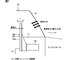
- the vehicle display device 100 of the first embodiment is mounted on the vehicle 10 and is applied to, for example, a car navigation device that displays the position of the own vehicle on a map, guidance information to a desired destination, and the like.
- the vehicle display device 100 can be used for displaying the operating state of various vehicle devices, for example, a car audio device, a car air conditioner device, a vehicle rear side display device, or the like. ..
- an organic EL panel 140 is used as a self-luminous display unit, and as shown in FIG. 1, the display surface 101a of the display main unit 101 is in a standing posture (vertical direction). Therefore, it is arranged so as to protrude above the dashboard 11 of the vehicle 10 in the central region in the vehicle width direction.
- This mounting form is so-called on-dash mounting.
- the image displayed on the display main body 101 is visually recognized by the user.
- the user is, for example, a driver.
- the display body 101 is susceptible to heat from sunlight (for example, direct sunlight) incident from the windshield 12 of the vehicle 10.
- the vehicle rear side of the vehicle display device 100 will be referred to as a user side
- the vehicle front side will be referred to as a rear side.
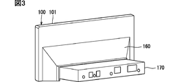
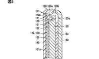
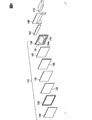
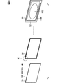
- the vehicle display device 100 includes a display panel 110, an outer frame 120, a touch panel 130, an organic EL panel 140, an inner frame 150, a heat conductive member 152, a heat insulating member 153, and a rear panel 160. It includes a communication unit 170, a cooling unit 180, and the like.
- the display main body 101 described above is mainly a portion formed by laminating the display panel 110, the outer frame 120, the touch panel 130, the organic EL panel 140, the inner frame 150, and the heat conductive member 152.
- the display panel 110 is a translucent (for example, transparent) plate-shaped member provided to protect the touch panel 130 and the organic EL panel 140.
- the display panel 110 is formed of, for example, a transparent resin member such as PMMA (polymethyl methacrylate resin) or PC (polycarbonate). Since the display panel 110 has translucency, the image formed by the organic EL panel 140 is transmitted and visually recognized by the user.
- the front shape of the display panel 110 is a horizontally long rectangle.
- a glass material or the like may also be used as the material of the display panel 110.
- the outer frame 120 is a frame-shaped contour forming portion arranged on the outer peripheral portion of the organic EL panel 140.
- the outer frame 120 can also be said to be a design member.
- the outer frame 120 is made of, for example, a resin material.
- the outer frame 120 has a flat outer peripheral portion 120a and a wall portion 120b that projects from the inner peripheral surface of the outer peripheral portion 120a to the inside of the frame to form an L-shaped cross section.
- the wall portion 120b is connected to a connecting portion 150a formed on the outer peripheral portion of the inner frame 150, which will be described later.
- the surface of the wall portion 120b on the display panel 110 side is an adhesive surface 120c.
- a narrow elastic adhesive 121 (or a liquid adhesive) having a cushioning property is provided on the adhesive surface 120c, and the outer peripheral portion on the back surface side of the display panel 110 is joined to the adhesive surface 120c. ..
- the touch panel 130 is an input operation unit for performing an input operation (for example, a finger operation) on the car navigation device, and is arranged on the back side of the display panel 110.
- the touch panel 130 has a touch panel sensor, a resin cover, and the like.
- the touch panel sensor is formed, for example, by joining transparent capacitance type electrode portions arranged in a matrix to the back surface of a transparent film member.
- the resin cover is a transparent thin-walled resin plate material that protects the touch panel sensor, and is provided on the user side of the touch panel sensor.
- the touch panel sensor (electrode unit) forms a capacitor between the user's finger and the finger via the resin cover to generate capacitance.
- the touch panel sensor and the resin cover are made of transparent members, the images of various information and the images of various operation icons on the organic EL panel 140 are transparently visually recognized by the user. It has become.
- the touch panel sensor changes the capacitance that occurs depending on the position of the operated finger when the user brings his or her finger close to any of the various operation icons (for example, about 5 mm) or when the user touches it with the finger. It is designed to be output to the communication unit 170, which will be described later, as the touch operation coordinate information.
- an optical transparent adhesive 122 having light transmission and elasticity is provided between the display panel 110 and the touch panel 130, and the display panel 110 and the touch panel 130 are joined to each other.
- the adhesive instead of the optical transparent adhesive 122, another transparent adhesive having elasticity may be used.
- the organic EL panel 140 displays various information images (for example, a map, a vehicle position, a destination guidance information image), images of various operation icons, and the like by emitting light of a plurality of pixels matrix-arranged on the display surface. It is a display unit and is arranged on the back side of the touch panel 130. "EL" of the organic EL panel 140 is an abbreviation for Electroluminescence. The organic EL panel 140 is also displayed as an OLED (Organic Light Emitting Diode).
- OLED Organic Light Emitting Diode
- the organic EL panel 140 is a self-luminous display unit and does not require a backlight like a liquid crystal type panel, for example, the thickness dimension of the display body unit 101 can be set extremely thin. (That is, it can be made thinner).
- the organic EL panel 140 is self-luminous and generates a certain amount of heat during operation due to the increase in internal heat density due to its thinness.
- the organic EL panel 140 has flexibility and can be bent or bent.
- the organic EL panel 140 has a control board 141.
- the control board 141 controls the display state of the image on the display surface of the organic EL panel 140.
- the control board 141 is connected to the organic EL panel 140 by the flexible wiring 141a.
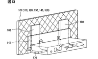
- the control board 141 is inserted into an insertion hole 150c provided in the inner frame 150, which will be described later, and is fixed to the back side of the inner frame 150 (FIGS. 11 to 13).
- the control board 141 is also a member that generates heat, like the organic EL panel 140.
- an optical transparent adhesive 135 having light transmission and elasticity is provided between the touch panel 130 and the organic EL panel 140, and the touch panel 130 and the organic EL panel 140 are joined to each other.
- the adhesive instead of the optical transparent adhesive 135, another transparent adhesive having elasticity may be used.
- optical transparent adhesive 122 and touch panel 130 may be abolished in the vehicle display device 100 that does not require finger operation.
- the organic EL panel 140 is bonded to the display panel 110 by the optical transparent adhesive 135.
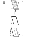
- the inner frame 150 is a metal member connected to the wall portion 120b of the outer frame 120 and arranged on the back side of the organic EL panel 140 in the inner region of the outer frame 120.
- the inner frame 150 is a skeleton member for obtaining the rigidity of the thinned display main body 101. Further, since the inner frame 150 is made of a metal member, it also serves as a member serving as a heat sink for the organic EL panel 140.
- the inner frame 150 is, for example, a metal molded product formed by die-casting using an alloy of aluminum and magnesium as a material, and a connecting portion 150a having an inverted L-shaped cross section is formed on the outer peripheral portion. There is.
- the connecting portion 150a is connected to the wall portion 120b of the outer frame 120.
- a reinforcing rib 150b projecting to the back surface side is formed so that the rigidity of the inner frame 150 itself can be increased. Further, by forming the reinforcing rib 150b on the inner frame 150, the surface area of the inner frame 150 is expanded, and the heat dissipation when functioning as a heat sink can be improved.
- An elongated insertion hole 150c extending along the lower side of the inner frame 150 is provided on the lower end side of the inner frame 150, and a plurality of fixing portions for fixing the control board 141 are provided on the back surface of the inner frame 150. It is provided. As described above, the control board 141 in the organic EL panel 140 is inserted into the insertion hole 150c and fixed to the back side of the inner frame 150.
- a narrow elastic adhesive 151 (or a liquid adhesive) having a cushioning property is provided on the four sides of the inner frame 150, which is the outer peripheral portion on the user side, on the back side of the organic EL panel 140.
- the outer peripheral portion is joined to the user-side surface of the inner frame 150.
- the elastic adhesive 151 may be set as needed and may be abolished.
- the heat conductive member 152 is arranged between the organic EL panel 140 and the inner frame 150 in an inner region surrounded by the elastic adhesive 151 having four sides, and heat generated by the organic EL panel 140 is transferred to the inner frame 150. It is a member that efficiently conveys to the side.
- the heat conductive member 152 is formed of a gel-like or sheet-like member, and the elastic adhesive 151 absorbs variations in dimensions in the thickness direction so that the organic EL panel 140 and the inner frame 150 face each other. It is designed to make sure contact with the surface to be used.
- the heat insulating member 153 is interposed between the inner frame 150 and the rear panel 160, which will be described later, to prevent heat from direct sunlight from being transmitted from the rear panel 160 side to the organic EL panel 140 side.
- the heat insulating member 153 is formed of, for example, a urethane-based independent foam, and is interposed between the inner frame 150 and the rear panel 160 in a compressed state to some extent (for example, about 30%).
- the heat insulating member 153 also plays a role of increasing the rigidity of the inner frame 150.
- the structure may be such that an air layer is provided between the inner frame 150 and the rear panel 160 without using the heat insulating member 153.
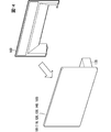
- the rear panel 160 has a flat plate shape on the upper side and a panel that bulges and opens on the lower side on the back side, and is a design member arranged on the back side of the inner frame 150.
- the inner frame 150, the heat insulating member 153, and the rear panel 160 described above have a three-layer structure, and play a role of further increasing the rigidity of the inner frame 150.
- the communication unit 170 has a flat box shape in the vertical direction and is a unit that communicates with the ECUs of other devices mounted on the vehicle 10, and is formed through an opening on the lower side of the rear panel 160. It is connected to the control board 141.
- the cooling unit 180 is a heat transfer means (in other words, a cooling means for cooling the inner frame 150) that releases heat generated in the inner frame 150 (that is, heat generated from the organic EL panel 140 and the control substrate 141) to the outside. Yes, for example, heat pipes are used.
- the cooling unit 180 has, for example, a pipe member having a flat cross section and an L-shaped overall shape in which the inside is evacuated and a refrigerant is sealed inside.
- One end side of the cooling unit 180 is interposed between the inner frame 150 and the control board 141, and is in contact with the inner frame 150 and the control board 141, respectively. Further, the other end side of the cooling unit 180 extends to the back surface side and is arranged in a region suitable for releasing heat.
- the position on the other end side can be set, for example, in the outer region of the communication unit 170, or in the inner region of the communication unit 170 when there is a cooling fan in the communication unit 170.
- the configuration of the vehicle display device 100 of the present embodiment is as described above, and its operation and action / effect will be described below.
- the light emitting state of each pixel on the display surface of the organic EL panel 140 is controlled by the control board 141 to obtain a predetermined image (for example, for example).
- a predetermined image for example, for example.
- a map, vehicle position, destination guidance information image, and images of various operation icons are displayed.
- the user can receive driving assistance based on the displayed image.
- the user can change the display state of the image (for example, enlarge / reduce the map) or display the destination guidance information by finger-operating the images of the various operation icons.
- the self-luminous organic EL panel 140 generates heat and is accompanied by a temperature rise.
- the organic EL panel 140 which does not require a backlight, is made thinner, but has a higher internal heat density and a higher degree of temperature rise.
- the inner frame 150 is made of metal, and the heat conductive member 152 is interposed between the organic EL panel 140 and the inner frame 150.
- the heat generated by the organic EL panel 140 can be effectively transferred to the inner frame 150 side via the heat conductive member 152 and further discharged to the outside.
- the metal inner frame 150 can function as a heat sink. Therefore, in the vehicle display device 100 mounted on the on-dash, the heat generated from the organic EL panel 140 can be effectively released, and the temperature rise of the organic EL panel 140 can be suppressed.
- control board 141 is also a member that generates heat and accompanies a temperature rise, but the control board 141 is fixed to the metal inner frame 150. As a result, the heat of the control board 141 can be transferred to the inner frame 150 and further discharged to the outside. Therefore, the temperature rise of the control board 141 can be suppressed.
- the inner frame 150 is provided with a cooling unit 180 (for example, a heat pipe) that releases the heat of the inner frame 150 to the outside.
- a cooling unit 180 for example, a heat pipe
- the heat of the organic EL panel 140 can be further and effectively released to the outside through the inner frame 150 and directly by the cooling unit 180.
- the vehicle display device 100 is mounted on-dash, for example, when parking in the summer, heat from direct sunlight is easily transmitted from the rear panel 160 side to the organic EL panel 140.
- the surface temperature of the rear panel 160 can rise to around 100 ° C.
- the heat insulating member 153 is interposed between the inner frame 150 and the rear panel 160. As a result, it is possible to suppress the heat from direct sunlight from being transferred to the organic EL panel 140 side.
- the inner frame 150 is made of metal, the rigidity of the inner frame 150 can be made higher than that of, for example, a resin one. Therefore, the overall rigidity of the vehicle display device 100, which is thinned by the adoption of the organic EL panel 140, is increased so that it can sufficiently withstand the external force F due to the user's hand push or the like indicated by the double-headed arrow in FIG. Can be done.
- the back side of the inner frame 150 has a three-layer structure of the inner frame 150, the heat insulating member 153, and the rear panel 160, the overall rigidity of the vehicle display device 100 can be further increased.
- the inner frame 150 is, for example, a metal molded product by die casting. As a result, unlike the sheet metal molded product (for example, a pressed product), it becomes easy to mold the connecting portion 150a with the outer frame 120, the reinforcing rib 150b on the back side, and the fixing portion for fixing the control board 141. ..
- the organic EL panel 140 is formed into a curved surface
- the inner frame 150 as a metal molded product
- the display device 100 can be used.
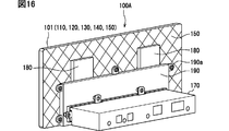
- the vehicle display device 100A of the second embodiment is shown in FIGS. 15 and 16.
- the second embodiment is obtained by adding the shield case 190 to the first embodiment.
- the shield case 190 is a metal member that blocks electrical noise generated from the control board 141 by covering the control board 141 fixed to the inner frame 150.
- a plurality of mounting portions 190a are formed on the outer peripheral portion of the shield case 190, and are fixed to the inner frame 150 by fastening members such as screws.
- a heat conductive member 191 similar to the heat conductive member 152 in the first embodiment is interposed between the control board 141 and the shield case 190. Further, one end side of the pipe member of the cooling unit 180 is in contact with the inner frame 150, and the other end side of the pipe member is arranged in a region suitable for releasing heat.
- the shield case 190 can shield the electrical noise generated from the control board 141 and effectively release the heat generated by the control board 141 to the outside. Further, by adding the shield case 190, the control board 141 can be protected even if water is received from above the vehicle display device 100A.
- the shield case 190 is fixed to the metal inner frame 150, so that the fixed structure of the shield case 190 can be easily formed.
- the communication unit 170 is attached to the shield case 190 as shown in FIG. 16 and can be connected to the control board 141.
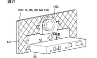
- cooling unit 180 has been described as using a heat pipe, but the present invention is not limited to this, and other cooling units using a cooling fan, for example, as shown in FIG. It may be 180A.
- the cooling unit 180A is a thin cooling fan in which a fan motor is set in the casing.
- a fan motor for example, a sirocco fan whose axial thickness dimension is set smaller than the radial dimension is used.
- the cooling unit 180A is arranged above the control board 141 of the inner frame 150, and is fixed to a mounting seat surface formed on the back side of the inner frame 150 with screws or the like.
- the cooling air generated by the fan of the cooling unit 180A flows from the inner frame 150 side to the center side of the fan, flows out in the circumferential direction, passes through the control board 141, and goes toward the communication unit 170 side. ..
- the cooling air flow may be directed from the outer side of the cooling unit 180A to the inner frame 150 side.
- the inner frame 150 can be cooled and the heat of the organic EL panel 140 and the control board 141 can be effectively released to the outside.
- the inner frame 150 is a metal molded product, a mounting seat surface for fixing the cooling unit 180A can be easily formed. Further, the power supply for the cooling unit 180A can be easily supplied from the control board 141.
- the mounting portion of the cooling unit 180A is not limited to the inner frame 150 as long as it blows air to cool the inner frame 150, and may be another portion such as the communication unit 170 or the shield case 190. Further, the power supply for the cooling unit 180A may be supplied from the communication unit 170.
- the organic EL panel 140 has been described as a typical example as the self-luminous display unit, but the present invention is not limited to this, and is applied to other fluorescent display tubes, inorganic EL displays, and the like. May be good.
- the outer frame 120 is made of resin, but may be made of metal.
- disclosure in this specification, drawings, etc. is not limited to the illustrated embodiment.
- the disclosure includes exemplary embodiments and modifications by those skilled in the art based on them.
- disclosure is not limited to the parts and / or element combinations shown in the embodiments. Disclosure can be carried out in various combinations. Disclosures can have additional parts that can be added to the embodiments.
- the disclosure includes parts and / or elements of the embodiment omitted. Disclosures include the replacement or combination of parts and / or elements between one embodiment and another.
- the technical scope disclosed is not limited to the description of the embodiments.
Landscapes
- Engineering & Computer Science (AREA)
- Physics & Mathematics (AREA)
- General Physics & Mathematics (AREA)
- Theoretical Computer Science (AREA)
- Mechanical Engineering (AREA)
- Devices For Indicating Variable Information By Combining Individual Elements (AREA)
- Electroluminescent Light Sources (AREA)
- Fittings On The Vehicle Exterior For Carrying Loads, And Devices For Holding Or Mounting Articles (AREA)
Applications Claiming Priority (2)
| Application Number | Priority Date | Filing Date | Title |
|---|---|---|---|
| JP2019-057167 | 2019-03-25 | ||
| JP2019057167A JP7036074B2 (ja) | 2019-03-25 | 2019-03-25 | 車両用表示装置 |
Publications (1)
| Publication Number | Publication Date |
|---|---|
| WO2020195111A1 true WO2020195111A1 (ja) | 2020-10-01 |
Family
ID=72609805
Family Applications (1)
| Application Number | Title | Priority Date | Filing Date |
|---|---|---|---|
| PCT/JP2020/002880 Ceased WO2020195111A1 (ja) | 2019-03-25 | 2020-01-28 | 車両用表示装置 |
Country Status (2)
| Country | Link |
|---|---|
| JP (1) | JP7036074B2 (https=) |
| WO (1) | WO2020195111A1 (https=) |
Cited By (1)
| Publication number | Priority date | Publication date | Assignee | Title |
|---|---|---|---|---|
| WO2022185770A1 (ja) * | 2021-03-05 | 2022-09-09 | 株式会社デンソー | 表示装置 |
Families Citing this family (1)
| Publication number | Priority date | Publication date | Assignee | Title |
|---|---|---|---|---|
| JP7552519B2 (ja) | 2021-07-05 | 2024-09-18 | 株式会社デンソー | 表示装置 |
Citations (5)
| Publication number | Priority date | Publication date | Assignee | Title |
|---|---|---|---|---|
| JP2006084977A (ja) * | 2004-09-17 | 2006-03-30 | Sony Corp | 表示装置 |
| JP2009157196A (ja) * | 2007-12-27 | 2009-07-16 | Hitachi Ltd | プラズマディスプレイ装置 |
| JP2009272073A (ja) * | 2008-05-01 | 2009-11-19 | Seiko Epson Corp | 有機el装置及び電子機器 |
| JP2013021357A (ja) * | 2012-09-26 | 2013-01-31 | Seiko Epson Corp | 有機el装置、有機el装置の製造方法、電子機器 |
| JP2018018842A (ja) * | 2016-07-25 | 2018-02-01 | 日本精機株式会社 | 放熱構造及び表示装置 |
Family Cites Families (2)
| Publication number | Priority date | Publication date | Assignee | Title |
|---|---|---|---|---|
| JP2011180476A (ja) | 2010-03-03 | 2011-09-15 | Panasonic Corp | 画像表示装置 |
| JP7049779B2 (ja) * | 2017-06-27 | 2022-04-07 | 株式会社デンソーテン | 表示装置 |
-
2019
- 2019-03-25 JP JP2019057167A patent/JP7036074B2/ja active Active
-
2020
- 2020-01-28 WO PCT/JP2020/002880 patent/WO2020195111A1/ja not_active Ceased
Patent Citations (5)
| Publication number | Priority date | Publication date | Assignee | Title |
|---|---|---|---|---|
| JP2006084977A (ja) * | 2004-09-17 | 2006-03-30 | Sony Corp | 表示装置 |
| JP2009157196A (ja) * | 2007-12-27 | 2009-07-16 | Hitachi Ltd | プラズマディスプレイ装置 |
| JP2009272073A (ja) * | 2008-05-01 | 2009-11-19 | Seiko Epson Corp | 有機el装置及び電子機器 |
| JP2013021357A (ja) * | 2012-09-26 | 2013-01-31 | Seiko Epson Corp | 有機el装置、有機el装置の製造方法、電子機器 |
| JP2018018842A (ja) * | 2016-07-25 | 2018-02-01 | 日本精機株式会社 | 放熱構造及び表示装置 |
Cited By (4)
| Publication number | Priority date | Publication date | Assignee | Title |
|---|---|---|---|---|
| WO2022185770A1 (ja) * | 2021-03-05 | 2022-09-09 | 株式会社デンソー | 表示装置 |
| JP2022135576A (ja) * | 2021-03-05 | 2022-09-15 | 株式会社デンソー | 表示装置 |
| JP7559624B2 (ja) | 2021-03-05 | 2024-10-02 | 株式会社デンソー | 表示装置 |
| US12532420B2 (en) | 2021-03-05 | 2026-01-20 | Denso Corporation | Display device |
Also Published As
| Publication number | Publication date |
|---|---|
| JP7036074B2 (ja) | 2022-03-15 |
| JP2020160169A (ja) | 2020-10-01 |
Similar Documents
| Publication | Publication Date | Title |
|---|---|---|
| KR102015035B1 (ko) | 차량용 인스트루먼트 패널 | |
| JP2012138300A (ja) | テレビおよび電子機器 | |
| JP7036074B2 (ja) | 車両用表示装置 | |
| CN112444994A (zh) | 佩戴型显示装置 | |
| WO2013129041A1 (ja) | ヘッドアップディスプレイ装置 | |
| WO2022185770A1 (ja) | 表示装置 | |
| CN109844605B (zh) | 包括热接触区的图像生成装置及相关的平视显示器 | |
| JP7268632B2 (ja) | 車載用表示装置 | |
| WO2014178175A1 (ja) | 車載用表示装置 | |
| JP2019008225A (ja) | 表示装置 | |
| JP7028216B2 (ja) | 車両用表示装置 | |
| JP6447822B2 (ja) | 車両用表示装置 | |
| JP2005024961A (ja) | 電気光学装置及び電子機器 | |
| JP7474028B2 (ja) | ヘッドアップディスプレイ | |
| US20200387030A1 (en) | Image generating device and associated head-up display | |
| JP2009079993A (ja) | 表示装置 | |
| CN113811815A (zh) | 热传导机构 | |
| JP2022191033A (ja) | 表示装置 | |
| JP2023033963A (ja) | 表示装置 | |
| JP2005181640A (ja) | 表示装置 | |
| JP2023003233A (ja) | 表示装置 | |
| JP2010006196A (ja) | 発光表示装置 | |
| CN116413938B (zh) | 显示设备 | |
| JP2006251600A (ja) | 表示パネル、表示装置、表示モジュール、および電子機器 | |
| JP7276234B2 (ja) | 表示装置および表示装置の製造方法 |
Legal Events
| Date | Code | Title | Description |
|---|---|---|---|
| 121 | Ep: the epo has been informed by wipo that ep was designated in this application |
Ref document number: 20779908 Country of ref document: EP Kind code of ref document: A1 |
|
| NENP | Non-entry into the national phase |
Ref country code: DE |
|
| 122 | Ep: pct application non-entry in european phase |
Ref document number: 20779908 Country of ref document: EP Kind code of ref document: A1 |