WO2020195016A1 - 管状部材洗浄装置、及び管状部材洗浄方法 - Google Patents
管状部材洗浄装置、及び管状部材洗浄方法 Download PDFInfo
- Publication number
- WO2020195016A1 WO2020195016A1 PCT/JP2020/000747 JP2020000747W WO2020195016A1 WO 2020195016 A1 WO2020195016 A1 WO 2020195016A1 JP 2020000747 W JP2020000747 W JP 2020000747W WO 2020195016 A1 WO2020195016 A1 WO 2020195016A1
- Authority
- WO
- WIPO (PCT)
- Prior art keywords
- tubular member
- stopper
- bobbin
- medium
- wiping medium
- Prior art date
- Legal status (The legal status is an assumption and is not a legal conclusion. Google has not performed a legal analysis and makes no representation as to the accuracy of the status listed.)
- Ceased
Links
Images




Classifications
-
- B—PERFORMING OPERATIONS; TRANSPORTING
- B08—CLEANING
- B08B—CLEANING IN GENERAL; PREVENTION OF FOULING IN GENERAL
- B08B9/00—Cleaning hollow articles by methods or apparatus specially adapted thereto
- B08B9/02—Cleaning pipes or tubes or systems of pipes or tubes
- B08B9/023—Cleaning the external surfaces
-
- B—PERFORMING OPERATIONS; TRANSPORTING
- B08—CLEANING
- B08B—CLEANING IN GENERAL; PREVENTION OF FOULING IN GENERAL
- B08B1/00—Cleaning by methods involving the use of tools
- B08B1/10—Cleaning by methods involving the use of tools characterised by the type of cleaning tool
- B08B1/14—Wipes; Absorbent members, e.g. swabs or sponges
-
- B—PERFORMING OPERATIONS; TRANSPORTING
- B08—CLEANING
- B08B—CLEANING IN GENERAL; PREVENTION OF FOULING IN GENERAL
- B08B1/00—Cleaning by methods involving the use of tools
- B08B1/10—Cleaning by methods involving the use of tools characterised by the type of cleaning tool
- B08B1/14—Wipes; Absorbent members, e.g. swabs or sponges
- B08B1/143—Wipes
-
- B—PERFORMING OPERATIONS; TRANSPORTING
- B21—MECHANICAL METAL-WORKING WITHOUT ESSENTIALLY REMOVING MATERIAL; PUNCHING METAL
- B21C—MANUFACTURE OF METAL SHEETS, WIRE, RODS, TUBES, PROFILES OR LIKE SEMI-MANUFACTURED PRODUCTS OTHERWISE THAN BY ROLLING; AUXILIARY OPERATIONS USED IN CONNECTION WITH METAL-WORKING WITHOUT ESSENTIALLY REMOVING MATERIAL
- B21C43/00—Devices for cleaning metal products combined with or specially adapted for use with machines or apparatus provided for in this subclass
Definitions
- the present disclosure mainly relates to a tubular member cleaning device and a tubular member cleaning method.
- synthetic resin-coated steel pipes in which the outer surface of steel pipes is coated with synthetic resin have excellent anticorrosion performance, and are widely used as buried steel pipes for gas pipes, oil pipelines, cable protection pipes, and the like.
- Such synthetic resin-coated steel pipes include, for example, polyethylene-coated steel pipes in which the outer surface of the steel pipe is coated with polyethylene.
- This polyethylene-coated steel pipe is formed by undercoating the outer surface of the steel pipe with an adhesive and then sequentially coating it with an anticorrosion layer containing a polyethylene-based resin and a packing layer also containing a polyethylene-based resin.
- Patent Document 1 discloses a descaling device that removes scale on the outer surface of a steel pipe with high-pressure water.
- Patent Document 1 may not be able to sufficiently remove foreign substances such as dust and scale adhering to the anticorrosion layer having high adhesive strength.
- fine foreign matter in the high-pressure water sprayed on the anticorrosion layer may newly adhere, and there is room for improvement.
- an object of the present invention is to provide a tubular member cleaning device capable of effectively removing foreign matter adhering to a tubular member such as a steel pipe, and a tubular member cleaning method. And.
- the tubular member cleaning device of the present disclosure is A tubular member cleaning device that cleans tubular members that move in the axial direction.
- the bobbin is provided with a bobbin moving means for moving the bobbin on an orbit along the outer peripheral surface of the tubular member on the radial outer side of the tubular member.
- the tubular member cleaning device of the present disclosure is provided on the downstream side in the moving direction of the tubular member with respect to the wiping medium, and is a stopper that restricts the wiping medium from moving downstream in the moving direction of the tubular member. It is preferable to further provide.
- the stopper is provided with at least a pair of stopper fixing members provided at positions facing each other in the radial direction with respect to the tubular member in a non-operating state of the stopper, and at least a pair of stopper fixing members. It has a stopper medium bridged between the stopper fixing members, and one of the stopper fixing members of the at least one pair of stopper fixing members moves in a plane orthogonal to the axis of the tubular member to form the tubular member. It is preferable that the stopper medium comes into contact with the stopper medium and shifts to the operating state of the stopper.
- the tension applied to the stopper medium is larger than the tension applied to the wiping medium in the above configuration.
- the bobbin moving means has a ring-shaped member that rotates around the radial outside of the tubular member at one location in the circumferential direction of the ring-shaped member. It is preferable that the bobbin is rotatably attached to the ring-shaped member.
- the tubular member cleaning device of the present disclosure preferably further includes a centering means for aligning the tubular member and the bobbin moving means.
- the centering means has a screw jack for moving the bobbin moving means in the vertical direction.
- the wiping medium includes a cloth or a sponge in the above configuration.
- the tubular member cleaning method of the present disclosure A tubular member cleaning method for cleaning tubular members that move in the axial direction.
- the tubular member cleaning method of the present disclosure preferably further includes a step of dropping a cleaning liquid onto the wiping medium in the above configuration.
- a tubular member cleaning device capable of effectively removing foreign matter adhering to a tubular member such as a steel pipe, and a tubular member cleaning method.
- tubular member cleaning device 100 and the tubular member cleaning method according to the embodiment of the present disclosure will be described in detail.
- the vertical direction is based on the vertical direction of FIG. 1A, with the side on which the screw jack 14a is arranged as the upper side and the side on which the stopper fixing members 12a and 12b are arranged as the lower side.
- the radial outside is a direction toward the outside along a straight line perpendicular to the axis O through the axis O of the ring-shaped member 6 in FIG. 1A, and the radial inside is a direction along the axis O along the straight line. It shall mean the direction to go.
- the tubular member cleaning device 100 has a bobbin 2 in which a long wiping medium 50 is wound and stored, and a wiping medium that fixes one end of the wiping medium 50 in the longitudinal direction.
- a bobbin moving means 9 for moving the fixing portion 4 and the bobbin 2 on a trajectory T (see FIGS. 1A and 4A) along the outer peripheral surface of the tubular member 70 on the radial outer side of the tubular member 70 (see FIG. 4B and the like). It includes a stopper 60 that restricts the wiping medium 50 from moving downstream in the moving direction of the tubular member 70, and a centering means 14 that aligns the tubular member 70 and the bobbin moving means 9.
- the tubular member 70 to be cleaned in the present embodiment is, for example, dust, machine oil, scale, etc. on the outer peripheral surface after forming the anticorrosion layer in the manufacturing process of the "polyethylene coated steel pipe" specified in JIS G 3469: 2016. It is a steel pipe to which foreign matter is attached.
- the present invention is not limited to this form, and a steel pipe other than the "polyethylene-coated steel pipe" or another tubular member such as a non-ferrous tubular member may be used.
- the wiping medium 50 is a long towel cloth.
- the wiping medium 50 is wound around the outer peripheral surface of the tubular member 70 while the bobbin 2 is rotated on the track T by the bobbin moving means 9 and a predetermined tension is applied. Therefore, in order to facilitate applying a predetermined tension to the wiping medium 50, it is preferable that the material of the wiping medium 50 has elasticity. Further, as will be described later, the wiping medium 50 wipes off dust and the like on the outer surface of the tubular member 70 in a moistened state by dropping a cleaning liquid. Therefore, it is preferable that the wiping medium 50 has a predetermined water absorption.
- the bobbin 2 has flange portions 2b at both ends in the axial direction of the shaft member 2a, and the wiping medium 50 is wound and stored on the outer peripheral surface of the shaft member 2a.
- the bobbin 2 is made of steel, and when the bobbin 2 rotates (rotates) relative to the ring-shaped member 6 described later by changing the magnetic flux from the permanent magnets arranged close to the shaft member 2a. The rotation resistance of the can be adjusted.
- a predetermined tension can be applied to the wiping medium 50 wound around the 70.
- the tension applied to the wiping medium 50 can be appropriately optimized depending on, for example, the material of the anticorrosion layer.
- the wiping medium fixing portion 4 is fixed to the wiping medium fixing portion 4 as shown in FIG. 1A and the like.
- the bobbin 2 revolves along the track T with one end of the wiping medium 50 fixed to the wiping medium fixing portion 4, so that the bobbin 2 is wiped with a predetermined tension applied in the longitudinal direction of the wiping medium 50.
- the medium 50 can be wound around the outer peripheral surface of the tubular member 70.
- the wiping medium fixing portion 4 is fixed to the floor, but may be fixed to the fixed frame 90 or the movable frame 95.
- the bobbin moving means 9 includes a ring-shaped member 6 that can rotate around the axis O, and a rotating means 8 that applies rotational torque to the ring-shaped member 6.
- the ring-shaped member 6 has a ring-shaped shape centered on the axis O when viewed from the front, and is supported by guide rollers (not shown) at six locations on the outer peripheral portion so as to be rotatable around the axis O. ..
- the ring-shaped member 6 has a mounting hole for mounting the bobbin 2 in a relative rotatable state at one position in the circumferential direction.
- the ring-shaped member 6 includes a set of permanent magnets arranged so as to face each other with respect to a disc portion protruding radially outward from the shaft member 2a of the attached bobbin 2.
- This set of permanent magnets By moving this set of permanent magnets relative to each other, the magnetic flux from the permanent magnets acting on the disk portion can be changed.
- the force that tends to prevent the rotation of the disc portion from the permanent magnet can be changed, so that the rotational resistance of the bobbin 2 with respect to the ring-shaped member 6 can be changed. Therefore, the rotational resistance of the bobbin 2 with respect to the ring-shaped member 6 can be adjusted by controlling the relative position of the permanent magnet.
- the rotating means 8 includes a transmission gear 8a and a bobbin revolution motor 8b that mesh with the gear portion 6b formed on the outer peripheral portion of the ring-shaped member 6 (however, the region where the guide roller described above does not abut).
- the rotational torque from the bobbin revolution motor 8b is transmitted to the gear portion 6b of the ring-shaped member 6 via the transmission gear 8a, so that the ring-shaped member 6 rotates around the axis O.
- the bobbin 2 attached to the ring-shaped member 6 has a trajectory T (FIGS. 1A and 4A) along the outer peripheral surface of the tubular member 70 on the radial outer side of the tubular member 70. Etc.) It is possible to move on.
- the stopper 60 is a pair of stoppers provided at positions facing each other in the radial direction with respect to the tubular member 70 (the outer peripheral surface when the tubular member 70 is arranged is shown by a broken line) in the non-operating state of the stopper 60 shown in FIG. 1A.
- a stopper medium 60a bridged between the stopper fixing members 10a and 12a and the stopper fixing members 10a and 12a is provided. As shown in the drawing, the stopper medium 60a hangs downward from the stopper fixing member 10a and is oriented toward the stopper fixing member 12a from an intermediate position, and has a substantially L-shape as a whole. In the non-operating state of the stopper 60 shown in FIG.
- the stopper medium 60a is arranged so as not to come into contact with the tubular member 70 even if the tubular member 70 passes through.
- the stopper 60 is also between the other pair of stopper fixing members 10b, 12b provided at positions that face each other in the radial direction with respect to the tubular member 70 in the non-operating state of the stopper 60, and the stopper fixing members 10b, 12b.
- the stopper medium 60b is provided.
- the stopper fixing members 10b and 12b and the stopper medium 60b are arranged at positions symmetrical with those of the stopper fixing members 10a and 12a and the stopper medium 60a described above in the non-operating state of the stopper 60 shown in FIG. 1A.
- the stopper fixing members 10a and 10b arranged above the tubular member 70 virtually shown in FIG. 1A are driven by the air cylinder 10 and can move horizontally along the rail 10c, respectively (in FIG. 1A, the cylinder, Control air supply port etc. are omitted).
- the stopper fixing member 10a is attached to the rail 10c on the back side of the paper surface of FIG. 1A
- the stopper fixing member 10b is attached to the rail 10c on the front side of the paper surface of FIG. 1A.
- the stopper fixing members 10a and 10b can move between the movable ranges on the rail 10c without interfering with each other.
- Both ends of the rail 10c are supported by a pair of rail support members 10d arranged at the left and right ends.
- the stopper 60 is configured to include two pairs of stopper fixing members 10a, 12a and 10b, 12b, and stopper media 60a, 60b bridged between them, but the present embodiment is limited to this embodiment. Instead, it may be configured to include only a pair of stopper fixing members 10a and 12a and a stopper medium 60a bridged between them. Further, the stopper fixing members 10a and 10b may be driven by, for example, an electromagnetic device other than the air cylinder 10.
- the bobbin moving means 9 described so far is arranged on the movable frame 95 shown in FIGS. 1A and 1B.
- the movable frame 95 is a frame movably supported in the vertical direction with respect to the fixed frame 90 forming the outer frame of the tubular member cleaning device 100, and is fixed to the screw shaft which is a movable portion of the screw jack 14a. .. Then, the rotational torque from the jack motor 14b is transmitted to the screw shaft through a worm reducer or the like, and the movable frame 95 fixed to the screw shaft moves in the vertical direction.
- the screw jack 14a By driving the screw jack 14a in this way, the movable frame 95 and the bobbin moving means 9 mounted on the movable frame 95 can be adjusted in the vertical direction. As a result, the tubular member 70 and the bobbin moving means 9 can be aligned with each other.
- the fixed frame 90 and the movable frame 95 can be locked so as not to be relatively movable by rotating the lever 91 shown in FIG. 1B or the like and inserting the lock pin 93 into the movable frame 95.
- the tubular member cleaning device 100 can be controlled by, for example, a control system 200 as shown in FIG.
- the control system 200 includes an electropneumatic (E / P) conversion unit 120 for controlling the air pressure supplied to the air cylinder 10, a current driver 130 for controlling the drive current supplied to the bobbin revolution motor 8b, and a jack motor. It is provided with a current driver 140 for controlling the drive current supplied to 14b.
- E / P electropneumatic
- the control unit 110 transmits a pressure control signal for controlling the air pressure supplied to the air cylinder 10 to the electropneumatic conversion unit 120.
- the electro-pneumatic conversion unit 120 adjusts the pressure of the pressurized air supplied from the air source 125 according to the pressure control signal generated by the control unit 110, and supplies the pressure to the air cylinder 10.
- the air cylinder 10 outputs a thrust corresponding to the pressure control signal and operates so that the stopper fixing members 10a and 10b are positioned at predetermined positions.
- the control unit 110 may acquire the position information of the stopper fixing members 10a and 10b and perform feedback control on the electropneumatic conversion unit 120.
- the control unit 110 transmits a current control signal for controlling the current supplied to the bobbin revolution motor 8b to the current driver 130.
- the current driver 130 outputs a drive current corresponding to the current control signal generated by the control unit 110 and supplies the drive current to the bobbin revolution motor 8b.
- the bobbin revolution motor 8b operates so as to output a rotational torque corresponding to the drive current to rotate the ring-shaped member 6.
- the control unit 110 may acquire the rotation angle of the ring-shaped member 6 and the like to feed-back control the current driver 130.
- the control unit 110 transmits a current control signal for controlling the current supplied to the jack motor 14b to the current driver 140.
- the current driver 140 outputs a drive current corresponding to the current control signal generated by the control unit 110 and supplies the drive current to the jack motor 14b.
- the jack motor 14b operates so as to output a rotational torque corresponding to the drive current to raise and lower the screw jack 14a.
- the control unit 110 may acquire the vertical position of the ring-shaped member 6 or the like and feed-back control the current driver 140.
- the operator rotates the lever 91 to move the lock pin 93 to the left. Pull it out (to the left of Fig. 1A).
- the lock pin 93 is released from the movable frame 95
- the lock of the movable frame 95 is released (step S101), and the movable frame 95 can be mechanically moved in the vertical direction with respect to the fixed frame 90. ..
- the screw jack 14a may be operated by unlocking the movable frame 95 and then unlocking the movable frame 95 to access the operation panel.
- the control unit 110 transmits a current control signal to the current driver 130 to raise and lower the screw jack 14a. Then, the vertical position of the movable frame 95 is adjusted so that the axis O of the ring-shaped member 6 and the axis of the tubular member 70 passing through the inside of the ring-shaped member 6 coincide with each other (step S103).
- the adjustment of the axial center position can be performed so that, for example, the axial center of the tubular member 70 obtained from the outer shape of the tubular member 70 and the axial center of the trajectory T of the bobbin 2 obtained from the outer shape of the ring-shaped member 6 coincide with each other. ..
- the tubular member 70 is carried by a polyethylene-coated steel pipe production line, and the left-right position of the axial center of the tubular member 70 in FIG. 4A and the left-right position of the axis O of the ring-shaped member 6 Is pre-aligned with the required accuracy. Therefore, here, only the vertical positions of both are adjustable, but the present invention is not limited to this mode.
- the axis O of the ring-shaped member 6 and the axis of the tubular member 70 may be aligned in two-dimensional directions in the left-right direction and the up-down direction.
- the operator prepares the bobbin 2 around which the wiping medium 50 is wound, and attaches the shaft member 2a of the bobbin 2 to the mounting hole formed in the ring-shaped member 6 (step S105).
- the initial position of the bobbin 2 can be a predetermined position relatively close to the wiping medium fixing portion 4, as shown in FIG. 1A, for example.
- step S107 the operator fixes one end of the wiping medium 50 wound around the bobbin 2 to the wiping medium fixing portion 4 (step S107). Up to this point, the preliminary preparation before the operation of the tubular member cleaning device 100 is completed.
- the operator attaches the stopper media 60a, 60b of the stopper 60 to the stopper fixing members 10a, 10b and 12a, 12b (step S109).
- the stopper medium 60a is mounted so that the stopper medium 60a hangs downward from the stopper fixing member 10a and is oriented toward the stopper fixing member 12a from an intermediate position, and has a substantially L-shape as a whole. Is doing.
- the stopper medium 60a is arranged so as not to come into contact with the tubular member 70 if the tubular member 70 passes through.
- the stopper 60 is hung between another pair of stopper fixing members 10b, 12b provided at positions facing each other in the radial direction with respect to the tubular member 70 in the non-operating state of the stopper 60, and the stopper fixing members 10b, 12b. It includes the passed stopper medium 60b.
- the stopper fixing members 10b and 12b and the stopper medium 60b are arranged at positions symmetrical with those of the stopper fixing members 10a and 12a and the stopper medium 60a described above in the non-operating state of the stopper 60 shown in FIG. 1A.
- the operator operates the manufacturing line of the tubular member 70 and moves the tubular member 70 to the right in FIG. 4B along the manufacturing line (step S111).
- the control unit 110 transmits a pressure control signal to the electropneumatic conversion unit 120 and drives the air cylinder 10 to transfer the stopper fixing members 10a and 10b to FIG. 4A.
- the stopper medium 60a passes through the left side surface of the tubular member 70 from the stopper fixing member 10a positioned on the upper right side of the movable frame 95 in front view, and the stopper fixing member 12a arranged on the lower right side of the fixing frame 90. It is bridged with a predetermined tension while drawing a substantially U-shape.
- the stopper medium 60b passes from the stopper fixing member 10b positioned on the upper left side of the movable frame 95 through the right side surface of the tubular member 70 to the stopper fixing member 12b arranged on the lower left side of the fixed frame 90. It is bridged with a predetermined tension while drawing a substantially U shape (step S113).
- the wiping medium 50 wound around the outer peripheral surface of the tubular member 70 does not move too much along with the tubular member 70.
- the movement can be restricted by the stopper media 60a and 60b.
- the two stopper fixing members 10a and 10b are simultaneously driven by one system of air pressure, but the present embodiment is not limited to this mode.
- the two stopper fixing members 10a and 10b may be individually driven by the air pressure of different systems. Further, the two stopper fixing members 10a and 10b do not necessarily have to be driven at the same time.
- the control unit 110 transmits a current control signal to the current driver 130 to drive the bobbin revolution motor 8b.
- the bobbin revolving motor 8b generates a rotational torque corresponding to the current supplied from the current driver 130, and rotates the transmission gear 8a to rotate a ring-shaped member 6 having a gear portion 6b that meshes with the transmission gear 8a around the axis O. Rotate drive.
- the bobbin 2 rotatably attached to the ring-shaped member 6 moves clockwise on the track T in front view as shown in FIG. 5 (step S115).
- bobbins 2 located at four locations in the circumferential direction are drawn.
- the wiping medium 50 is wound around the outer peripheral surface of the tubular member 70 over three turns (step S117).
- a permanent magnet is arranged in the vicinity of the shaft member 2a of the bobbin 2, and rotational resistance is generated by the magnetic flux from the permanent magnet. Therefore, when the bobbin 2 revolves with the rotation of the ring-shaped member 6, the wiping medium 50 is unwound from the bobbin 2 and wound around the outer peripheral surface of the tubular member 70 while being pulled by the tension corresponding to the above-mentioned rotational resistance. As a result, the wiping medium 50 is wound tightly on the outer peripheral surface of the tubular member 70. Therefore, when the tubular member 70 moves along the line toward the front of the paper surface in FIG.
- the wiping medium 50 in close contact with the outer peripheral surface of the tubular member 70 wipes off the foreign matter adhering to the tubular member 70 by relative movement with the tubular member 70.
- the tension applied to the stopper media 60a and 60b is larger than the tension applied to the wiping medium 50. Thereby, it is possible to effectively limit the movement of the wiping medium 50 to the downstream side with the movement of the tubular member 70.
- the present embodiment is a tubular member cleaning device 100 that cleans a tubular member 70 that moves in the axial direction, and is a bobbin 2 in which a long wiping medium 50 is wound and stored, and a bobbin 2 for wiping.
- a wiping medium fixing portion 4 for fixing one end of the medium 50 in the longitudinal direction and a bobbin moving means 9 for moving the bobbin 2 on the track T along the outer peripheral surface of the tubular member 70 on the radial outer side of the tubular member 70 are provided. It was configured as follows. By adopting such a configuration, foreign matter adhering to the tubular member 70 such as a steel pipe can be effectively removed. In particular, in the present embodiment, it is possible to automate by eliminating the manual wiping of foreign matter by the operator, so that the working time can be shortened.
- a stopper 60 is further provided on the downstream side in the moving direction of the tubular member 70 with respect to the wiping medium 50, and restricts the wiping medium 50 from moving in the downstream side in the moving direction of the tubular member 70. Configured. By adopting such a configuration, it is possible to limit the excessive movement of the wiping medium 50 with the movement of the tubular member 70 to the downstream side, and to prevent the wiping medium 50 and its supporting member from being damaged. Can be done.
- the stopper 60 is at least paired with at least a pair of stopper fixing members 10a and 12a (10b and 12b) provided at positions facing each other in the radial direction with respect to the tubular member 70 in the non-operating state of the stopper 60.
- the stopper media 60a and 60b are bridged between the stopper fixing members 10a and 12a (10b and 12b), and at least one of the stopper fixing members 10a and 12a (10b and 12b) has one stopper fixing member.
- the tension applied to the stopper media 60a and 60b is configured to be larger than the tension applied to the wiping medium 50.
- the bobbin moving means 9 has a ring-shaped member 6 that rotates the radial outside of the tubular member 70 around the axis O, and the bobbin 2 rings at one position in the circumferential direction of the ring-shaped member 6. It is configured so that it can be attached to the shape member 6 so as to be relatively rotatable. By adopting such a configuration, the wiping medium 50 can be tightly adhered to the tubular member 70 without the operator directly touching the tubular member 70.
- the centering means 14 for aligning the tubular member 70 and the bobbin moving means 9 is further provided.
- the centering means 14 is configured to have a screw jack 14a for moving the bobbin moving means 9 in the vertical direction.
- the bobbin moving means 9 can be accurately positioned in the vertical direction by the screw jack 14a.
- the wiping medium 50 is configured to include a cloth or a sponge.
- the wiping medium 50 can have both elasticity and water absorption, so that the wiping medium 50 is given an appropriate tension and the wiping medium 50 is impregnated with the cleaning liquid to remove foreign substances. Can be enhanced.
- the present embodiment is a tubular member cleaning method for cleaning a tubular member 70 that moves in the axial direction, in which a step of preparing a bobbin 2 around which a long wiping medium 50 is wound and a step of preparing the bobbin 2 of the wiping medium 50 are provided.
- a step of fixing one end in the longitudinal direction and a step of moving the bobbin 2 on the track T along the outer peripheral surface of the tubular member 70 on the radial outer side of the tubular member 70 are included.
- the step of dropping the cleaning liquid onto the wiping medium 50 is further included.
- the wiping medium 50 can always be kept moist with the cleaning liquid to enhance the cleaning effect.
- the wiping medium 50 is configured to include a stopper 60 that restricts the movement of the tubular member 70 to the downstream side in the moving direction, but the present embodiment is not limited to this, and the stopper 60 is not provided. May be.
- the stopper 60 is a stopper medium 60a bridged between two pairs of stopper fixing members 10a, 12a and 10b, 12b and a pair of stopper fixing members 10a, 12a (10b, 12b). (60b), and one of the stopper fixing members 10a (10b) moves horizontally in a plane orthogonal to the axis of the tubular member 70, so that the tubular member 70 and the stopper medium 60a (60b) are tightly adhered to each other. It is configured to shift to the operating state of the stopper 60 by (contacting), but the present invention is not limited to this mode.
- one of the stopper fixing members 10a (10b) is configured to move in the vertical direction in a plane orthogonal to the axis of the tubular member 70 so that the tubular member 70 and the stopper medium 60a (60b) are in close contact with each other. May be good.
- the stopper 60 does not necessarily have to have two pairs of stopper fixing members 10a, 12a and 10b, 12b, and may have at least a pair of stopper fixing members 10a, 12a (10b, 12b). ..
- the tension applied to the stopper media 60a and 60b is configured to be larger than the tension applied to the wiping medium 50, but the present invention is not limited to this mode, and the magnitude relation of each tension is opposite. You may.
- the bobbin moving means 9 is configured to have the ring-shaped member 6, but the present invention is not limited to this embodiment, and other means capable of moving the bobbin 2 along the outer peripheral surface of the tubular member 70. May be used.
- the driving means of the ring-shaped member 6 may be, for example, a pneumatic device, a hydraulic device, or the like other than the electromagnetic motor.
- the alignment means 14 for aligning the tubular member 70 and the bobbin moving means 9 is provided, but the present invention is not limited to this embodiment, and the alignment means 14 is not provided. May be good. Further, the centering means 14 may include a feeding mechanism other than the screw jack 14a.
- the cloth of the towel cloth is used as the material of the wiping medium 50, but the present invention is not limited to this embodiment.
- the material of the wiping medium 50 may be a cloth other than the towel cloth, a sponge, or the like.
Landscapes
- Engineering & Computer Science (AREA)
- Mechanical Engineering (AREA)
- Cleaning In General (AREA)
Abstract
鋼管等の管状部材に付着する異物を効果的に除去することができる管状部材洗浄装置、及び管状部材洗浄方法を提供する。本開示は、軸方向に移動する管状部材70を洗浄する管状部材洗浄装置100であって、長尺状の拭き取り媒体50が巻回され格納されるボビン2と、拭き取り媒体50の長手方向の一端を固定する拭き取り媒体固定部4と、ボビン2を、管状部材70の径方向外側において管状部材70の外周面に沿う軌道T上を移動させるボビン移動手段9とを備えることを特徴とする。
Description
本出願は、2019年 3月22日に出願された日本国特許出願第2019- 55247号に基づく優先権を主張するものであり、この特許出願の明細書全体を参照によって本願明細書に引用する。
本開示は、主に管状部材洗浄装置、及び管状部材洗浄方法に関するものである。
従来、鋼管の外面に合成樹脂を被覆した合成樹脂被覆鋼管は、防食性能に優れており、ガス導管、石油パイプライン及びケーブル保護管等の埋設用鋼管として広く用いられている。
このような合成樹脂被覆鋼管には、例えば鋼管の外面にポリエチレンを被覆したポリエチレン被覆鋼管がある。このポリエチレン被覆鋼管は、鋼管の外面に粘着剤をアンダーコートした後、ポリエチレン系樹脂を含む防食層と、同じくポリエチレン系樹脂を含む梱包層とにより順次被覆することによって形成されている。
ところで、上述の防食層を被覆した後に、鋼管の外周面に埃、機械油、スケール等の異物が付着すると、その後に梱包層を被覆したときに上述の異物が原因で外観不良が発生することがあった。
このような問題に対し、例えば特許文献1には、高圧水により鋼管の外面のスケールを除去するデスケーリング装置が開示されている。
しかし、特許文献1に記載のデスケーリング装置では、粘着力が高い防食層に付着した埃、スケール等の異物を十分に除去することができない場合があった。また、防食層に吹き付ける高圧水中の微細な異物が新たに付着してしまう場合があり、改善の余地があった。
本開示は、このような事情に鑑み開発されたもので、鋼管等の管状部材に付着する異物を効果的に除去することができる管状部材洗浄装置、及び管状部材洗浄方法を提供することを目的とする。
本開示の管状部材洗浄装置は、
軸方向に移動する管状部材を洗浄する管状部材洗浄装置であって、
長尺状の拭き取り媒体が巻回され格納されるボビンと、
前記拭き取り媒体の長手方向の一端を固定する拭き取り媒体固定部と、
前記ボビンを、前記管状部材の径方向外側において前記管状部材の外周面に沿う軌道上を移動させるボビン移動手段と
を備えることを特徴とする。
軸方向に移動する管状部材を洗浄する管状部材洗浄装置であって、
長尺状の拭き取り媒体が巻回され格納されるボビンと、
前記拭き取り媒体の長手方向の一端を固定する拭き取り媒体固定部と、
前記ボビンを、前記管状部材の径方向外側において前記管状部材の外周面に沿う軌道上を移動させるボビン移動手段と
を備えることを特徴とする。
本開示の管状部材洗浄装置は、上記構成において、前記拭き取り媒体よりも前記管状部材の移動方向下流側に設けられ、前記拭き取り媒体が前記管状部材の移動方向下流側へ移動するのを制限するストッパを更に備えることが好ましい。
本開示の管状部材洗浄装置は、上記構成において、前記ストッパは、該ストッパの非作動状態において前記管状部材に関して径方向に対向する位置に設けられた少なくとも一対のストッパ固定部材と、該少なくとも一対のストッパ固定部材の間に架け渡されたストッパ媒体とを有し、前記少なくとも一対のストッパ固定部材の一方のストッパ固定部材が前記管状部材の軸線に直交する面内を移動することで前記管状部材と前記ストッパ媒体とが接触し前記ストッパの作動状態へとシフトすることが好ましい。
本開示の管状部材洗浄装置は、上記構成において、前記ストッパ媒体にかかる張力は、前記拭き取り媒体にかかる張力よりも大きいことが好ましい。
本開示の管状部材洗浄装置は、上記構成において、前記ボビン移動手段は、前記管状部材の径方向外側を軸線周りに回転するリング状部材を有し、該リング状部材の周方向の1箇所において前記ボビンが前記リング状部材に対して相対回転可能に取り付けられていることが好ましい。
本開示の管状部材洗浄装置は、上記構成において、前記管状部材と前記ボビン移動手段との芯合わせを行う調芯手段を更に備えることが好ましい。
本開示の管状部材洗浄装置は、上記構成において、前記調芯手段は、前記ボビン移動手段を上下方向に移動させるスクリュージャッキを有することが好ましい。
本開示の管状部材洗浄装置は、上記構成において、前記拭き取り媒体は布又はスポンジを含むことが好ましい。
本開示の管状部材洗浄方法は、
軸方向に移動する管状部材を洗浄する管状部材洗浄方法であって、
長尺状の拭き取り媒体が巻回されたボビンを準備するステップと、
前記拭き取り媒体の長手方向の一端を固定するステップと、
前記ボビンを、前記管状部材の径方向外側において前記管状部材の外周面に沿う軌道上を移動させるステップと
を含むことを特徴とする。
軸方向に移動する管状部材を洗浄する管状部材洗浄方法であって、
長尺状の拭き取り媒体が巻回されたボビンを準備するステップと、
前記拭き取り媒体の長手方向の一端を固定するステップと、
前記ボビンを、前記管状部材の径方向外側において前記管状部材の外周面に沿う軌道上を移動させるステップと
を含むことを特徴とする。
本開示の管状部材洗浄方法は、上記構成において、前記拭き取り媒体に洗浄液を滴下するステップを更に含むことが好ましい。
本開示によれば、鋼管等の管状部材に付着する異物を効果的に除去することができる管状部材洗浄装置、及び管状部材洗浄方法を提供することができる。
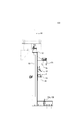
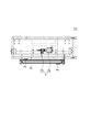
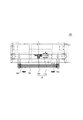
以下、図1A~図5を参照して、本開示の一実施形態に係る管状部材洗浄装置100、及び管状部材洗浄方法について詳細に例示説明する。
なお、本明細書において上下方向とは、図1Aの上下方向を基準とし、スクリュージャッキ14aが配置される側を上方、ストッパ固定部材12a,12bが配置される側を下方とする。また、径方向外側とは、図1Aにおけるリング状部材6の軸線Oを通り軸線Oに垂直な直線に沿って外側に向かう方向であり、径方向内側とは、当該直線に沿って軸線Oに向かう方向を意味するものとする。
図1Aに示すように、本実施形態に係る管状部材洗浄装置100は、長尺状の拭き取り媒体50が巻回され格納されるボビン2と、拭き取り媒体50の長手方向の一端を固定する拭き取り媒体固定部4と、ボビン2を管状部材70(図4B等参照)の径方向外側において管状部材70の外周面に沿う軌道T(図1A、図4A参照)上を移動させるボビン移動手段9と、拭き取り媒体50が管状部材70の移動方向下流側へ移動するのを制限するストッパ60と、管状部材70とボビン移動手段9との芯合わせを行う調芯手段14とを備えている。
本実施形態において洗浄の対象となる管状部材70は、例えばJIS G 3469:2016において規定されている「ポリエチレン被覆鋼管」の製造工程において、防食層形成後の外周面に埃、機械油、スケール等の異物が付着した鋼管である。しかし、この形態に限定されるものではなく、「ポリエチレン被覆鋼管」以外の鋼管や、非鉄管状部材等の他の管状部材であってもよい。
本実施形態において、拭き取り媒体50は、長尺状のタオル地の布である。拭き取り媒体50は、後述するようにボビン2がボビン移動手段9により軌道T上を回転することで所定の張力を与えられながら管状部材70の外周面に巻き付けられる。従って、拭き取り媒体50に所定の張力を与え易くするために、拭き取り媒体50の材質として伸縮性を備えていることが好ましい。また、拭き取り媒体50は、後述するように、洗浄液を滴下して湿らせた状態で管状部材70の外面上の埃等を拭き取る。従って、拭き取り媒体50は、所定の吸水性を備えていることが好ましい。
ボビン2は、図1A及び図1Bに示すように、軸材2aの軸線方向両端にフランジ部2bを有しており、軸材2aの外周面には、拭き取り媒体50が巻回され格納されている。本実施形態においてボビン2は鋼鉄製であり、軸材2aに近接配置された永久磁石からの磁束を変化させることで、ボビン2が後述するリング状部材6に対して相対回転(自転)する際の回転抵抗を調整することができる。これによって、後述するようにリング状部材6を軸線O周りに回転させてボビン2を公転させる際に、ボビン2がリング状部材6に対して容易に相対回転しないようにすることで、管状部材70に巻かれる拭き取り媒体50に所定の張力をかけることができる。なお、拭き取り媒体50に与える張力は、例えば防食層の材質等によって適宜最適化することができる。
拭き取り媒体50の長手方向の一端は、図1A等に示すように、拭き取り媒体固定部4に固定されている。このように拭き取り媒体50の一端が拭き取り媒体固定部4に固定された状態でボビン2が軌道Tに沿って公転することで、拭き取り媒体50の長手方向に所定の張力がかけられた状態で拭き取り媒体50を管状部材70の外周面に巻き付けることができる。なお、図1Aの例では、拭き取り媒体固定部4は、床に固定されているが、固定フレーム90に対して固定したり可動フレーム95に対して固定してもよい。
ボビン移動手段9は、図1Aに示すように、軸線O周りに回転可能なリング状部材6と、リング状部材6に回転トルクを与える回転手段8とを備えている。リング状部材6は、正面視で軸線Oを中心とするリング状形状を備えており、外周部の6か所において図示しないガイドローラにより支持されることで軸線O周りに回転可能とされている。リング状部材6は、周方向の1箇所においてボビン2を相対回転可能な状態で取り付けるための取り付け穴を有している。リング状部材6は、取り付けられたボビン2の軸材2aから径方向外側に突出するディスク部に関して対向配置された1組の永久磁石を備えている。この1組の永久磁石を相対移動させることでディスク部に作用する永久磁石からの磁束を変化させることができる。この磁束の変化によって、永久磁石からのディスク部の回転を妨げようとする力を変化させることができるため、リング状部材6に対するボビン2の回転抵抗を変化することができる。従って、永久磁石の相対位置制御によって、リング状部材6に対するボビン2の回転抵抗を調整することができる。
回転手段8は、リング状部材6の外周部(但し、上述のガイドローラが当接しない領域)に形成されたギヤ部6bに噛み合う変速ギヤ8aとボビン公転モータ8bとを備えている。ボビン公転モータ8bからの回転トルクが変速ギヤ8aを介してリング状部材6のギヤ部6bに伝達されることで、リング状部材6は軸線O周りに回転する。
リング状部材6が軸線O周りに回転することで、リング状部材6に取り付けられたボビン2は、管状部材70の径方向外側において管状部材70の外周面に沿う軌道T(図1A、図4A等参照)上を移動可能である。
ストッパ60は、図1Aに示すストッパ60の非作動状態において管状部材70(管状部材70が配置されたときの外周面を破線で示している)に関して径方向に対向する位置に設けられた一対のストッパ固定部材10a,12aと、ストッパ固定部材10a,12aの間に架け渡されたストッパ媒体60aを備えている。ストッパ媒体60aは、図示のようにストッパ固定部材10aから下方に垂下するとともに途中位置からストッパ固定部材12aに向けて方向付けられており、全体として略L字形状をなしている。図1Aに示すストッパ60の非作動状態では、仮に管状部材70が通過した場合にもストッパ媒体60aが管状部材70に接触しないように配置されている。同様に、ストッパ60はまた、ストッパ60の非作動状態において管状部材70に関して径方向に対向する位置に設けられた他の一対のストッパ固定部材10b,12bと、ストッパ固定部材10b,12bの間に架け渡されたストッパ媒体60bを備えている。ストッパ固定部材10b,12b及びストッパ媒体60bは、図1Aに示すストッパ60の非作動状態において上述のストッパ固定部材10a,12a及びストッパ媒体60aとは線対称となる位置に配置されている。
図1Aに仮想的に示す管状部材70の上方に配置されているストッパ固定部材10a,10bはエアシリンダ10により駆動され、それぞれレール10cに沿って水平方向に移動可能である(図1Aにおいてシリンダ、制御エア供給ポート等は省略されている)。図1A~図1Cに示すように、ストッパ固定部材10aは、図1Aの紙面の奥側のレール10cに取り付けられており、ストッパ固定部材10bは、図1Aの紙面の手前側のレール10cに取り付けられている。これによって、ストッパ固定部材10a,10bは、それぞれレール10c上の可動範囲の間で互いに干渉することなく移動することができる。レール10cは、左右端部に配置されている一対のレール支持部材10dにより両端を支持されている。
本実施形態では、ストッパ60が、二対のストッパ固定部材10a,12a並びに10b,12bと、それらの間に架け渡されるストッパ媒体60a,60bを備えるように構成したが、この態様には限定されず、一対のストッパ固定部材10a,12aと、その間に架け渡されるストッパ媒体60aのみを備えるように構成してもよい。また、ストッパ固定部材10a,10bは、エアシリンダ10以外の例えば電磁デバイス等によって駆動されるようにしてもよい。
これまで説明してきたボビン移動手段9は、図1A及び図1Bに示す可動フレーム95上に配置されている。可動フレーム95は、管状部材洗浄装置100の外枠を形成する固定フレーム90に対して上下方向に移動可能に支持されたフレームであり、スクリュージャッキ14aの可動部であるスクリューシャフトに固定されている。そして、ジャッキモータ14bからの回転トルクがウォーム減速機等を通じてスクリューシャフトに伝達され、スクリューシャフトに固定された可動フレーム95が上下方向に移動する。このように、スクリュージャッキ14aを駆動させることで可動フレーム95及び当該可動フレーム95に搭載されたボビン移動手段9を上下方向に位置調整することができる。これによって、管状部材70とボビン移動手段9との芯合わせを行うことができる。
なお、固定フレーム90と可動フレーム95とは、図1B等に示すレバー91を回動し、ロックピン93を可動フレーム95に対して挿入することで相対移動不能にロックすることができる。
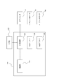
管状部材洗浄装置100は、例えば図2に示すような制御系200により制御することができる。制御系200は、エアシリンダ10に供給する空気圧を制御するための電空(E/P)変換部120と、ボビン公転モータ8bに供給する駆動電流を制御するための電流ドライバ130と、ジャッキモータ14bに供給する駆動電流を制御するための電流ドライバ140とを備えている。なお、図2において破線は各種制御信号の経路を示している。
制御部110は、エアシリンダ10に供給する空気圧を制御するための圧力制御信号を電空変換部120に送信する。電空変換部120は、エア源125から供給される加圧エアの圧力を、制御部110が生成する圧力制御信号に応じて調整して、エアシリンダ10に供給する。これによって、エアシリンダ10は、圧力制御信号に応じた推力を出力して、ストッパ固定部材10a,10bが所定の位置に位置決めされるように動作する。制御部110は、ストッパ固定部材10a,10bの位置情報を取得して、電空変換部120をフィードバック制御するようにしてもよい。
制御部110は、ボビン公転モータ8bに供給する電流を制御するための電流制御信号を電流ドライバ130に送信する。電流ドライバ130は、制御部110が生成する電流制御信号に応じた駆動電流を出力してボビン公転モータ8bに供給する。これによって、ボビン公転モータ8bは、駆動電流に応じた回転トルクを出力してリング状部材6を回転させるように動作する。制御部110は、リング状部材6の回転角等を取得して、電流ドライバ130をフィードバック制御するようにしてもよい。
制御部110は、ジャッキモータ14bに供給する電流を制御するための電流制御信号を電流ドライバ140に送信する。電流ドライバ140は、制御部110が生成する電流制御信号に応じた駆動電流を出力してジャッキモータ14bに供給する。これによって、ジャッキモータ14bは、駆動電流に応じた回転トルクを出力してスクリュージャッキ14aを昇降させるように動作する。制御部110は、リング状部材6等の上下方向位置を取得して、電流ドライバ140をフィードバック制御するようにしてもよい。
制御部110は、一以上のCPU(Central Processing Unit)、DSP(Digital Signal Processor)、又はマイクロコントローラ等でプログラムを実行することによりソフトウエア処理で実現したり、ASIC(Application Specific Integrated Circuit)、PLD(Programmable Logic Device)、又はFPGA(Field Programmable Gate Array)等によりハードウエア処理で実現することができる。
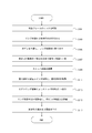
次に、図3等を用いて、本実施形態に係る管状部材洗浄方法を実施する手順を説明する。
本実施形態に係る管状部材洗浄方法を実施するに際しては、まず、図1A~図1Cに示す管状部材洗浄装置100の初期状態において、作業者は、レバー91を回転させてロックピン93を左方(図1Aの左方)に引き抜く。これによって、可動フレーム95からロックピン93が抜けて可動フレーム95のロックが解除され(ステップS101)、可動フレーム95は、固定フレーム90に対して機構的に上下方向への相対移動が可能となる。なお、上述の可動フレーム95のロックを解除した後、更に操作盤にアクセスするためのロックを解除することによりスクリュージャッキ14aの操作が可能となるように構成してもよい。
次に、作業者の操作に基づいて、制御部110は、電流ドライバ130に電流制御信号を送信してスクリュージャッキ14aを昇降させる。そして、リング状部材6の軸線Oと、リング状部材6の内側を通過する管状部材70の軸心が一致するように可動フレーム95の上下方向位置を調整する(ステップS103)。この軸心位置の調整は、例えば管状部材70の外形から求まる管状部材70の軸心と、リング状部材6の外形から求まるボビン2の軌道Tの軸心とが一致するように行うことができる。
なお、本実施形態では、管状部材70は、ポリエチレン被覆鋼管の製造ラインによって運ばれており、管状部材70の軸心の図4Aにおける左右方向位置と、リング状部材6の軸線Oの左右方向位置とはあらかじめ必要な精度で位置合わせされている。従って、ここでは両者の上下方向位置のみを調整可能に構成しているが、この態様には限定されない。リング状部材6の軸線Oと管状部材70の軸心とを左右方向及び上下方向の2次元方向に芯合わせするように構成してもよい。
次に、作業者は、拭き取り媒体50が巻回されたボビン2を準備し、ボビン2の軸材2aをリング状部材6に形成された取り付け穴に取り付ける(ステップS105)。なお、ボビン2の初期位置は、例えば図1Aに示すように、拭き取り媒体固定部4に比較的近い所定位置とすることができる。
次に、作業者は、ボビン2に巻回された拭き取り媒体50の一端を拭き取り媒体固定部4に固定する(ステップS107)。ここまでで、管状部材洗浄装置100の稼働前の事前準備が完了する。
次に、作業者は、ストッパ60のストッパ媒体60a,60bをストッパ固定部材10a,10b並びに12a,12bに装着する(ステップS109)。ストッパ媒体60aは、図1Aに示すように、ストッパ媒体60aがストッパ固定部材10aから下方に垂下するとともに途中位置からストッパ固定部材12aに向けて方向付けられるように装着され、全体として略L字形状をなしている。図1Aに示すストッパ60の非作動状態では、仮に管状部材70が通過した場合にストッパ媒体60aが管状部材70に接触しないように配置されている。同様に、ストッパ60は、ストッパ60の非作動状態において管状部材70に関して径方向に対向する位置に設けられた他の一対のストッパ固定部材10b,12bと、ストッパ固定部材10b,12bの間に架け渡されたストッパ媒体60bを備えている。ストッパ固定部材10b,12b及びストッパ媒体60bは、図1Aに示すストッパ60の非作動状態において上述のストッパ固定部材10a,12a及びストッパ媒体60aとは線対称となる位置に配置されている。
次に、作業者は、管状部材70の製造ラインを稼働させ、管状部材70を製造ラインに沿って図4Bの右方向に移動させる(ステップS111)。管状部材70がストッパ固定部材10a,10bの下方を通過すると、制御部110は、電空変換部120に圧力制御信号を送信し、エアシリンダ10を駆動してストッパ固定部材10a,10bを図4A、図4Cに示す位置まで移動させる。すなわち、ストッパ固定部材10aは、図4Aに矢印で示すように正面視でレール10c上を左端から右端まで移動し、ストッパ固定部材10bは、レール10c上を右端から左端まで移動する。これによって、ストッパ媒体60aは、正面視で可動フレーム95の上部右側に位置決めされたストッパ固定部材10aから管状部材70の左側面を通って、固定フレーム90の下部右側に配置されたストッパ固定部材12aまでの間に略U字型を描きながら所定の張力で架け渡される。同様に、ストッパ媒体60bは、可動フレーム95の上部左側に位置決めされたストッパ固定部材10bから管状部材70の右側面を通って、固定フレーム90の下部左側に配置されたストッパ固定部材12bまでの間に略U字型を描きながら所定の張力で架け渡される(ステップS113)。このような構成によって、管状部材70が図4Aの紙面の手前側に移動する際に、管状部材70の外周面に巻回された拭き取り媒体50が管状部材70に伴って移動し過ぎないようにストッパ媒体60a,60bによって移動を制限することができる。
なお、本実施形態では、一系統のエア圧力により2つのストッパ固定部材10a,10bを同時に駆動させるように構成したが、この態様には限定されない。2つのストッパ固定部材10a,10bは、別系統のエア圧力により個別に駆動されてもよい。また、2つのストッパ固定部材10a,10bは必ずしも同時に駆動させなくてもよい。
次に、制御部110は、電流ドライバ130に電流制御信号を送信し、ボビン公転モータ8bを駆動する。ボビン公転モータ8bは、電流ドライバ130から供給された電流に対応する回転トルクを発生し、変速ギヤ8aを回転させることで変速ギヤ8aに噛み合うギヤ部6bを有するリング状部材6を軸線O周りに回転駆動させる。これによって、リング状部材6に自転可能に取り付けられたボビン2は、図5に示すように軌道T上を正面視で時計回りに移動する(ステップS115)。なお、図5には、周方向の4か所に位置するボビン2が描かれている。このようにして、管状部材70の外周面には拭き取り媒体50が3周にわたって巻き付けられる(ステップS117)。上述のように、ボビン2が有する軸材2aの近傍には永久磁石が配置されており、永久磁石からの磁束によって回転抵抗が発生する。従って、ボビン2がリング状部材6の回転に伴って公転すると、拭き取り媒体50がボビン2から繰り出され、上述の回転抵抗に対応する張力で引っ張られながら管状部材70の外周面に巻き付けられる。これによって、拭き取り媒体50は、管状部材70の外周面にきつく密着しながら巻き付けられる。従って、管状部材70がラインに沿って図5の紙面手前方向に移動すると、管状部材70の外周面に密着した拭き取り媒体50が管状部材70との相対移動により管状部材70に付着した異物を拭き取る(洗浄する)ことができる。拭き取り媒体50には、洗浄液を滴下することが好ましい。洗浄液には、水等を用いてもよい。
なお、ストッパ媒体60a,60bにかかる張力は、拭き取り媒体50にかかる張力よりも大きいことが好ましい。これによって、拭き取り媒体50が管状部材70の移動に伴って下流側に移動するのを効果的に制限することができる。
以上述べたように、本実施形態は、軸方向に移動する管状部材70を洗浄する管状部材洗浄装置100であって、長尺状の拭き取り媒体50が巻回され格納されるボビン2と、拭き取り媒体50の長手方向の一端を固定する拭き取り媒体固定部4と、ボビン2を、管状部材70の径方向外側において管状部材70の外周面に沿う軌道T上を移動させるボビン移動手段9とを備えるように構成した。このような構成の採用によって、鋼管等の管状部材70に付着する異物を効果的に除去することができる。特に本実施形態では、作業者の手作業による異物の拭き取りを無くして自動化することができるので、作業時間を短縮することができる。
また、本実施形態では、拭き取り媒体50よりも管状部材70の移動方向下流側に設けられ、拭き取り媒体50が管状部材70の移動方向下流側へ移動するのを制限するストッパ60を更に備えるように構成した。このような構成の採用によって、拭き取り媒体50が管状部材70の下流側への移動に伴って過剰に移動するのを制限して、拭き取り媒体50やその支持部材等が破損するのを抑制することができる。
また、本実施形態では、ストッパ60は、ストッパ60の非作動状態において管状部材70に関して径方向に対向する位置に設けられた少なくとも一対のストッパ固定部材10a及び12a(10b及び12b)と、少なくとも一対のストッパ固定部材10a及び12a(10b及び12b)の間に架け渡されたストッパ媒体60a,60bとを有し、少なくとも一対のストッパ固定部材10a及び12a(10b及び12b)の一方のストッパ固定部材が管状部材70の軸線に直交する面内を移動することで管状部材70とストッパ媒体60a,60bとが接触しストッパ60の作動状態へとシフトするように構成した。このような構成の採用によって、作業者が管状部材70に直接触れることなくストッパ60を装着することができる。
また、本実施形態では、ストッパ媒体60a,60bにかかる張力は、拭き取り媒体50にかかる張力よりも大きいように構成した。このような構成の採用によって、拭き取り媒体50が管状部材70の移動に伴って下流側に移動するのを効果的に制限することができる。
また、本実施形態では、ボビン移動手段9は、管状部材70の径方向外側を軸線O周りに回転するリング状部材6を有し、リング状部材6の周方向の1箇所においてボビン2がリング状部材6に対して相対回転可能に取り付けられるように構成した。このような構成の採用によって、作業者が管状部材70に直接触れることなく拭き取り媒体50を管状部材70にきつく密着させることができる。
また、本実施形態では、管状部材70とボビン移動手段9との芯合わせを行う調芯手段14を更に備えるように構成した。このような構成の採用によって、拭き取り媒体50を管状部材70の外周面に巻き付ける際の張力変動を抑制することができるので、管状部材70の外周面における異物除去効果を安定化させることができる。
また、本実施形態では、調芯手段14は、ボビン移動手段9を上下方向に移動させるスクリュージャッキ14aを有するように構成した。このような構成の採用によって、ボビン移動手段9をスクリュージャッキ14aにより上下方向に精度良く位置決めすることができる。
また、本実施形態では、拭き取り媒体50は布又はスポンジを含むように構成した。このような構成の採用によって、拭き取り媒体50が伸縮性と吸水性とを兼ね備えることができるため、拭き取り媒体50に適度な張力を与えると共に拭き取り媒体50内に洗浄液を含侵させて異物の除去効果を高めることができる。
また、本実施形態は、軸方向に移動する管状部材70を洗浄する管状部材洗浄方法であって、長尺状の拭き取り媒体50が巻回されたボビン2を準備するステップと、拭き取り媒体50の長手方向の一端を固定するステップと、ボビン2を、管状部材70の径方向外側において管状部材70の外周面に沿う軌道T上を移動させるステップとを含むように構成した。このような構成の採用によって、鋼管等の管状部材70に付着する異物を効果的に除去することができる。特に本実施形態では、作業者の手作業による異物の拭き取りを無くして自動化することができるので、作業時間を短縮することができる。
また、本実施形態では、拭き取り媒体50に洗浄液を滴下するステップを更に含むように構成した。このような構成の採用によって、拭き取り媒体50を常に洗浄液で湿った状態に維持して洗浄効果を高めることができる。
本開示を諸図面や実施例に基づき説明してきたが、当業者であれば本開示に基づき種々の変形や修正を行うことが容易であることに注意されたい。従って、これらの変形や修正は本発明の範囲に含まれることに留意されたい。例えば、各構成部に含まれる機能などは論理的に矛盾しないように再配置可能であり、複数の構成部を1つに組み合わせたり、或いは分割したりすることが可能である。本発明の範囲にはこれらも包含されるものと理解されたい。
例えば、本実施形態では、拭き取り媒体50が管状部材70の移動方向下流側へ移動するのを制限するストッパ60を備えるように構成したが、この態様には限定されず、ストッパ60を設けない構成としてもよい。
また、本実施形態では、ストッパ60は、二対のストッパ固定部材10a,12a並びに10b、12bと、対になるストッパ固定部材10a,12a(10b、12b)の間に架け渡されたストッパ媒体60a(60b)とを有し、一方のストッパ固定部材10a(10b)が管状部材70の軸線に直交する面内を水平方向に移動することで管状部材70とストッパ媒体60a(60b)とをきつく密着(接触)させることでストッパ60の作動状態へとシフトするように構成したが、この態様には限定されない。例えば、一方のストッパ固定部材10a(10b)が管状部材70の軸線に直交する面内を鉛直方向に移動することで管状部材70とストッパ媒体60a(60b)とをきつく密着させるように構成してもよい。また、ストッパ60は、必ずしも二対のストッパ固定部材10a,12a並びに10b、12bを有している必要はなく、少なくとも一対のストッパ固定部材10a,12a(10b、12b)を有していればよい。
また、本実施形態では、ストッパ媒体60a,60bにかかる張力は、拭き取り媒体50にかかる張力よりも大きくなるように構成したが、この態様には限定されず、各張力の大小関係は逆であってもよい。
また、本実施形態では、ボビン移動手段9はリング状部材6を有するように構成したが、この態様には限定されず、ボビン2を管状部材70の外周面に沿って移動可能な他の手段を用いてもよい。また、リング状部材6の駆動手段は、電磁モータ以外の例えば、空圧デバイス、油圧デバイス等であってもよい。
また、本実施形態では、管状部材70とボビン移動手段9との芯合わせを行う調芯手段14を備えるように構成したが、この態様には限定されず、調芯手段14を備えていなくてもよい。また、調芯手段14は、スクリュージャッキ14a以外の送り機構を備えていてもよい。
また、本実施形態では、拭き取り媒体50の材料としてタオル地の布を用いるように構成したが、この態様には限定されない。拭き取り媒体50の材料としては、タオル地以外の布や、スポンジ等であってもよい。
2 ボビン
2a 軸材
2b フランジ部
4 拭き取り媒体固定部
6 リング状部材
6b ギヤ部
8 回転手段
8a 変速ギヤ
8b ボビン公転モータ
9 ボビン移動手段
10 エアシリンダ
10a,10b ストッパ固定部材
10c レール
10d レール支持部材
12a,12b ストッパ固定部材
14 調芯手段
14a スクリュージャッキ
14b ジャッキモータ
50 拭き取り媒体
60 ストッパ
60a,60b ストッパ媒体
70 管状部材
90 固定フレーム
91 移動レバー
93 ロックピン
95 可動フレーム
100 管状部材洗浄装置
110 制御部
120 電空変換部
125 エア源
130 電流ドライバ
140 電流ドライバ
200 制御系
O 軸線
2a 軸材
2b フランジ部
4 拭き取り媒体固定部
6 リング状部材
6b ギヤ部
8 回転手段
8a 変速ギヤ
8b ボビン公転モータ
9 ボビン移動手段
10 エアシリンダ
10a,10b ストッパ固定部材
10c レール
10d レール支持部材
12a,12b ストッパ固定部材
14 調芯手段
14a スクリュージャッキ
14b ジャッキモータ
50 拭き取り媒体
60 ストッパ
60a,60b ストッパ媒体
70 管状部材
90 固定フレーム
91 移動レバー
93 ロックピン
95 可動フレーム
100 管状部材洗浄装置
110 制御部
120 電空変換部
125 エア源
130 電流ドライバ
140 電流ドライバ
200 制御系
O 軸線
Claims (10)
- 軸方向に移動する管状部材を洗浄する管状部材洗浄装置であって、
長尺状の拭き取り媒体が巻回され格納されるボビンと、
前記拭き取り媒体の長手方向の一端を固定する拭き取り媒体固定部と、
前記ボビンを、前記管状部材の径方向外側において前記管状部材の外周面に沿う軌道上を移動させるボビン移動手段と
を備えることを特徴とする管状部材洗浄装置。 - 前記拭き取り媒体よりも前記管状部材の移動方向下流側に設けられ、前記拭き取り媒体が前記管状部材の移動方向下流側へ移動するのを制限するストッパを更に備える、請求項1に記載の管状部材洗浄装置。
- 前記ストッパは、該ストッパの非作動状態において前記管状部材に関して径方向に対向する位置に設けられた少なくとも一対のストッパ固定部材と、該少なくとも一対のストッパ固定部材の間に架け渡されたストッパ媒体とを有し、前記少なくとも一対のストッパ固定部材の一方のストッパ固定部材が前記管状部材の軸線に直交する面内を移動することで前記管状部材と前記ストッパ媒体とが接触し前記ストッパの作動状態へとシフトする、請求項2に記載の管状部材洗浄装置。
- 前記ストッパ媒体にかかる張力は、前記拭き取り媒体にかかる張力よりも大きい、請求項3に記載の管状部材洗浄装置。
- 前記ボビン移動手段は、前記管状部材の径方向外側を軸線周りに回転するリング状部材を有し、該リング状部材の周方向の1箇所において前記ボビンが前記リング状部材に対して相対回転可能に取り付けられている、請求項1から4のいずれか一項に記載の管状部材洗浄装置。
- 前記管状部材と前記ボビン移動手段との芯合わせを行う調芯手段を更に備える、請求項1から5のいずれか一項に記載の管状部材洗浄装置。
- 前記調芯手段は、前記ボビン移動手段を上下方向に移動させるスクリュージャッキを有する、請求項6に記載の管状部材洗浄装置。
- 前記拭き取り媒体は布又はスポンジを含む、請求項1から7のいずれか一項に記載の管状部材洗浄装置。
- 軸方向に移動する管状部材を洗浄する管状部材洗浄方法であって、
長尺状の拭き取り媒体が巻回されたボビンを準備するステップと、
前記拭き取り媒体の長手方向の一端を固定するステップと、
前記ボビンを、前記管状部材の径方向外側において前記管状部材の外周面に沿う軌道上を移動させるステップと
を含むことを特徴とする管状部材洗浄方法。 - 前記拭き取り媒体に洗浄液を滴下するステップを更に含む、請求項9に記載の管状部材洗浄方法。
Priority Applications (1)
| Application Number | Priority Date | Filing Date | Title |
|---|---|---|---|
| CN202080009082.XA CN113286669B (zh) | 2019-03-22 | 2020-01-10 | 管状构件清洗装置和管状构件清洗方法 |
Applications Claiming Priority (2)
| Application Number | Priority Date | Filing Date | Title |
|---|---|---|---|
| JP2019055247A JP7006644B2 (ja) | 2019-03-22 | 2019-03-22 | 管状部材洗浄装置、及び管状部材洗浄方法 |
| JP2019-055247 | 2019-03-22 |
Publications (1)
| Publication Number | Publication Date |
|---|---|
| WO2020195016A1 true WO2020195016A1 (ja) | 2020-10-01 |
Family
ID=72557065
Family Applications (1)
| Application Number | Title | Priority Date | Filing Date |
|---|---|---|---|
| PCT/JP2020/000747 Ceased WO2020195016A1 (ja) | 2019-03-22 | 2020-01-10 | 管状部材洗浄装置、及び管状部材洗浄方法 |
Country Status (3)
| Country | Link |
|---|---|
| JP (1) | JP7006644B2 (ja) |
| CN (1) | CN113286669B (ja) |
| WO (1) | WO2020195016A1 (ja) |
Cited By (1)
| Publication number | Priority date | Publication date | Assignee | Title |
|---|---|---|---|---|
| CN115532746A (zh) * | 2022-11-10 | 2022-12-30 | 深圳市博为医疗机器人有限公司 | 一种内镜清洗设备 |
Citations (4)
| Publication number | Priority date | Publication date | Assignee | Title |
|---|---|---|---|---|
| JPS54136761U (ja) * | 1978-03-14 | 1979-09-21 | ||
| JP2007127710A (ja) * | 2005-11-01 | 2007-05-24 | Showa Denko Kk | アルミニウム管の製造方法 |
| JP2007130641A (ja) * | 2005-11-08 | 2007-05-31 | Showa Denko Kk | アルミニウム管の製造方法 |
| JP2008272772A (ja) * | 2007-04-26 | 2008-11-13 | Showa Denko Kk | アルミニウム管の製造方法 |
Family Cites Families (4)
| Publication number | Priority date | Publication date | Assignee | Title |
|---|---|---|---|---|
| KR101002424B1 (ko) * | 2010-04-23 | 2010-12-21 | (주) 디아이엔바이로 | Uv살균램프를 위한 스파이럴 와이퍼 시스템 |
| CN103920677B (zh) * | 2014-04-16 | 2015-11-25 | 常熟市给排水工程有限公司 | 钢管清洗装置 |
| CN107876514B (zh) * | 2017-11-15 | 2020-11-13 | 浙江杭海镀锌钢管有限公司 | 一种长钢管外表面的清洗装置 |
| CN208341276U (zh) * | 2017-12-31 | 2019-01-08 | 河北胜华钢管有限公司 | 一种钢管清洗装置 |
-
2019
- 2019-03-22 JP JP2019055247A patent/JP7006644B2/ja active Active
-
2020
- 2020-01-10 WO PCT/JP2020/000747 patent/WO2020195016A1/ja not_active Ceased
- 2020-01-10 CN CN202080009082.XA patent/CN113286669B/zh active Active
Patent Citations (4)
| Publication number | Priority date | Publication date | Assignee | Title |
|---|---|---|---|---|
| JPS54136761U (ja) * | 1978-03-14 | 1979-09-21 | ||
| JP2007127710A (ja) * | 2005-11-01 | 2007-05-24 | Showa Denko Kk | アルミニウム管の製造方法 |
| JP2007130641A (ja) * | 2005-11-08 | 2007-05-31 | Showa Denko Kk | アルミニウム管の製造方法 |
| JP2008272772A (ja) * | 2007-04-26 | 2008-11-13 | Showa Denko Kk | アルミニウム管の製造方法 |
Cited By (1)
| Publication number | Priority date | Publication date | Assignee | Title |
|---|---|---|---|---|
| CN115532746A (zh) * | 2022-11-10 | 2022-12-30 | 深圳市博为医疗机器人有限公司 | 一种内镜清洗设备 |
Also Published As
| Publication number | Publication date |
|---|---|
| JP7006644B2 (ja) | 2022-01-24 |
| CN113286669A (zh) | 2021-08-20 |
| CN113286669B (zh) | 2022-12-27 |
| JP2020151686A (ja) | 2020-09-24 |
Similar Documents
| Publication | Publication Date | Title |
|---|---|---|
| US7597282B2 (en) | Changeover apparatus and method for changing over winding of web | |
| CN103874573B (zh) | 线缆胎圈的制造方法及其装置 | |
| CN111918199B (zh) | 膜片装配系统及扬声器装配系统 | |
| US4785512A (en) | Machine for repairing and sealing conduits | |
| JP7006644B2 (ja) | 管状部材洗浄装置、及び管状部材洗浄方法 | |
| JP2009542556A (ja) | 浮動紙継ぎ装置 | |
| JP5067172B2 (ja) | 鋼管内面塗装装置 | |
| CN107790527B (zh) | 用于使线状工件弯曲的方法和装置 | |
| JPWO2019093003A1 (ja) | フィラメントワインディング装置 | |
| CN206579913U (zh) | 光纤盘覆膜包装机 | |
| JP2009066752A (ja) | 機械ツールのキャリッジ構造 | |
| KR20180100321A (ko) | 인출 장치 및 인출 방법 | |
| JP5243259B2 (ja) | 核燃料棒の自動汚染除去のための装置および方法 | |
| JP6628409B2 (ja) | 溶射加工装置および溶射加工基材の製造方法 | |
| JP2001354360A (ja) | 綾巻ボビンを巻成する繊維機械の運転法 | |
| JP2858610B2 (ja) | 配管内面研削装置 | |
| JPS62275524A (ja) | 細径金属管の曲げ加工装置 | |
| JP2014215494A (ja) | ラビング処理方法及び装置 | |
| JP5219895B2 (ja) | Rfidラベルロール自動巻取装置 | |
| TW200909079A (en) | Brush cleaning apparatus | |
| JPH07291126A (ja) | 管内走行体 | |
| JP2016175761A (ja) | 巻取り装置 | |
| CN120244153B (zh) | 一种焊接机器人的自动焊接系统及焊接方法 | |
| CN120714817B (zh) | 一种多轴支撑喷涂定位装置 | |
| CN119340858B (zh) | 电气布线机器人 |
Legal Events
| Date | Code | Title | Description |
|---|---|---|---|
| 121 | Ep: the epo has been informed by wipo that ep was designated in this application |
Ref document number: 20778154 Country of ref document: EP Kind code of ref document: A1 |
|
| NENP | Non-entry into the national phase |
Ref country code: DE |
|
| 122 | Ep: pct application non-entry in european phase |
Ref document number: 20778154 Country of ref document: EP Kind code of ref document: A1 |