WO2020195005A1 - ロータの製造方法、およびモータの製造方法 - Google Patents
ロータの製造方法、およびモータの製造方法 Download PDFInfo
- Publication number
- WO2020195005A1 WO2020195005A1 PCT/JP2020/000564 JP2020000564W WO2020195005A1 WO 2020195005 A1 WO2020195005 A1 WO 2020195005A1 JP 2020000564 W JP2020000564 W JP 2020000564W WO 2020195005 A1 WO2020195005 A1 WO 2020195005A1
- Authority
- WO
- WIPO (PCT)
- Prior art keywords
- radial
- magnetic member
- rotor
- magnetizing
- magnetized
- Prior art date
Links
Images

Classifications
-
- H—ELECTRICITY
- H02—GENERATION; CONVERSION OR DISTRIBUTION OF ELECTRIC POWER
- H02K—DYNAMO-ELECTRIC MACHINES
- H02K1/00—Details of the magnetic circuit
- H02K1/06—Details of the magnetic circuit characterised by the shape, form or construction
- H02K1/22—Rotating parts of the magnetic circuit
- H02K1/27—Rotor cores with permanent magnets
- H02K1/2706—Inner rotors
- H02K1/272—Inner rotors the magnetisation axis of the magnets being perpendicular to the rotor axis
- H02K1/274—Inner rotors the magnetisation axis of the magnets being perpendicular to the rotor axis the rotor consisting of two or more circumferentially positioned magnets
- H02K1/2753—Inner rotors the magnetisation axis of the magnets being perpendicular to the rotor axis the rotor consisting of two or more circumferentially positioned magnets the rotor consisting of magnets or groups of magnets arranged with alternating polarity
- H02K1/278—Surface mounted magnets; Inset magnets
- H02K1/2783—Surface mounted magnets; Inset magnets with magnets arranged in Halbach arrays
-
- H—ELECTRICITY
- H02—GENERATION; CONVERSION OR DISTRIBUTION OF ELECTRIC POWER
- H02K—DYNAMO-ELECTRIC MACHINES
- H02K1/00—Details of the magnetic circuit
- H02K1/06—Details of the magnetic circuit characterised by the shape, form or construction
- H02K1/22—Rotating parts of the magnetic circuit
- H02K1/27—Rotor cores with permanent magnets
- H02K1/2706—Inner rotors
- H02K1/2713—Inner rotors the magnetisation axis of the magnets being axial, e.g. claw-pole type
-
- H—ELECTRICITY
- H02—GENERATION; CONVERSION OR DISTRIBUTION OF ELECTRIC POWER
- H02K—DYNAMO-ELECTRIC MACHINES
- H02K15/00—Methods or apparatus specially adapted for manufacturing, assembling, maintaining or repairing of dynamo-electric machines
- H02K15/02—Methods or apparatus specially adapted for manufacturing, assembling, maintaining or repairing of dynamo-electric machines of stator or rotor bodies
- H02K15/03—Methods or apparatus specially adapted for manufacturing, assembling, maintaining or repairing of dynamo-electric machines of stator or rotor bodies having permanent magnets
Definitions
- the present invention relates to a method for manufacturing a rotor and a method for manufacturing a motor.
- Patent Document 1 describes a motor in which permanent magnets are arranged in a Halbach array.
- a permanent magnet may be made by fixing a magnetic member made of a magnetic material to a rotor core and then magnetizing the magnetic member. In this case, if a hole is provided in the rotor core for, for example, positioning, the flow of magnetic flux passing through the magnetic member at the time of magnetization becomes poor, and there is a risk that the magnetic member becomes difficult to magnetize.
- one of the objects of the present invention is to provide a method for manufacturing a rotor and a method for manufacturing a motor, which easily magnetize a magnetic member.
- One aspect of the rotor manufacturing method of the present invention is a rotor manufacturing method including a rotor core that can rotate about a central axis and a rotor magnet fixed to the outer peripheral surface of the rotor core, and the outer peripheral surface of the rotor core. It includes a magnetizing step of magnetizing a first magnetic member fixed to the rotor magnet to make the rotor magnet.
- the rotor core has a hole portion recessed from one side surface in the axial direction of the rotor core to the other side in the axial direction.
- the first magnetic member is magnetized with the second magnetic member made of a magnetic material inserted into the hole.
- One aspect of the motor manufacturing method of the present invention includes the above rotor manufacturing method.
- the magnetic member is easily magnetized when the rotor is manufactured.
- FIG. 1 is a cross-sectional view showing a rotary wing device of the present embodiment.
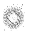
- FIG. 2 is a cross-sectional view showing the rotor and the stator of the present embodiment, and is a cross-sectional view taken along the line II-II in FIG.
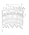
- FIG. 3 is a perspective view showing a part of the rotor magnet and a part of the stator of the present embodiment.
- FIG. 4 is a cross-sectional view showing the rotor and the stator of the present embodiment, and is a partially enlarged view of FIG.
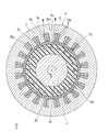
- FIG. 5 is a cross-sectional view showing a part of the procedure of the rotor manufacturing method of the present embodiment.
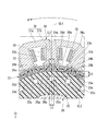
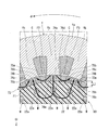
- FIG. 6 is a cross-sectional view showing a part of the procedure of the rotor manufacturing method of the present embodiment, and is a partially enlarged view of FIG.
- the Z-axis direction shown in each figure is a vertical direction in which the positive side is the "upper side” and the negative side is the “lower side”.
- the central axis J appropriately shown in each figure is a virtual line that is parallel to the Z-axis direction and extends in the vertical direction.
- the axial direction of the central axis J that is, the direction parallel to the vertical direction
- the radial direction centered on the central axis J is simply referred to as "radial direction”.
- the circumferential direction centered on is simply called the "circumferential direction”.
- the side that goes counterclockwise in the circumferential direction when viewed from the upper side to the lower side is called “one side in the circumferential direction”.
- the side that moves clockwise in the circumferential direction when viewed from the upper side to the lower side is called the “other side in the circumferential direction”.
- One side in the circumferential direction is the side that advances in the direction of the arrow ⁇ shown in FIGS. 2 to 6.
- the other side in the circumferential direction is the side that advances in the direction opposite to the direction of the arrow ⁇ shown in FIGS. 2 to 6.
- the lower side corresponds to one side in the axial direction
- the upper side corresponds to the other side in the axial direction.
- the vertical direction, the upper side, and the lower side are simply names for explaining the arrangement relationship of each part, and the actual arrangement relationship, etc. may be an arrangement relationship other than the arrangement relationship, etc. indicated by these names. Good.
- the motor 10 of this embodiment is mounted on the rotor blade device 1.
- the rotary wing device 1 is mounted on an unmanned aerial vehicle, for example.
- the rotary blade device 1 includes a motor 10 and a propeller 2.
- the motor 10 is an inner rotor type motor.
- the motor 10 includes a housing 40, a stator 30, a bus bar assembly 60, a rotor 20, a first bearing 71, a second bearing 72, a propeller mounting portion 80, and a sensor assembly 50.
- the housing 40 internally houses the rotor 20, the stator 30, the sensor assembly 50, the bus bar assembly 60, the first bearing 71, and the second bearing 72.
- a plurality of fins 45 arranged along the circumferential direction are provided on the outer peripheral surface of the housing 40.
- the stator 30 is located on the outer side in the radial direction of the rotor 20.
- the stator 30 has a stator core 31, an insulator 32, and a plurality of coils 33.
- the stator core 31 has a core back 31a and a plurality of teeth 31b.
- the core back 31a is an annular shape surrounding the central axis J.
- the core back 31a is, for example, an annular shape centered on the central axis J.
- the plurality of teeth 31b extend radially inward from the core back 31a.
- the plurality of teeth 31b are arranged at equal intervals along the circumferential direction. For example, 18 teeth 31b are provided.
- the plurality of coils 33 are mounted on the stator core 31 via the insulator 32. More specifically, the plurality of coils 33 are respectively mounted on the plurality of teeth 31b via the insulator 32. In FIGS. 2 and 3, the insulator 32 is not shown.
- the bus bar assembly 60 is located below the stator 30.
- the bus bar assembly 60 is located radially outside the sensor assembly 50.
- the bus bar assembly 60 has a bus bar holder 61 and a bus bar 62.
- the bus bar holder 61 holds the bus bar 62.
- the bus bar 62 is electrically connected to the coil 33.
- the rotor 20 can rotate about the central axis J.
- the rotor 20 is located inside the stator 30 in the radial direction.
- the rotor 20 includes a shaft 21, a rotor core 22, and a rotor magnet 23.
- the shaft 21 is arranged along the central axis J.
- the shaft 21 is a columnar shape extending in the axial direction about the central axis J. The upper end of the shaft 21 projects upward from the housing 40.
- the rotor core 22 is fixed to the outer peripheral surface of the shaft 21.
- the rotor core 22 is an annular shape surrounding the central axis J.
- the rotor core 22 is an annular shape centered on the central axis J.
- the rotor core 22 can rotate about the central axis J together with the shaft 21.
- the rotor core 22 is a non-magnetic member made of a non-magnetic material.
- the rotor core 22 is made of resin, for example.
- the rotor core 22 may be made of a non-magnetic metal such as aluminum.
- the rotor core 22 has a hole portion 22a that is recessed downward from the upper surface of the rotor core 22.
- the hole portion 22a is a through hole that penetrates the rotor core 22 in the axial direction.
- a plurality of hole portions 22a are provided at intervals along the circumferential direction.
- the plurality of hole portions 22a are arranged at equal intervals over one circumference in the circumferential direction.
- 20 holes 22a are provided.
- the number of holes 22a is, for example, the same as the number of poles of the rotor 20.
- the hole portion 22a has a shape that is line-symmetrical with respect to the circumferential center line CL1 when viewed along the axial direction.
- the circumferential center line CL1 is a virtual line that passes through the circumferential center of the radial magnetization portion 23b, which will be described later, when viewed along the axial direction.
- the hole portion 22a has, for example, a square shape when viewed along the axial direction.
- the hole portion 22a is located at a position radially inward from the outer peripheral surface of the rotor core 22.
- the hole portion 22a is provided in a portion of the rotor core 22 that is closer to the outer side in the radial direction.
- the hole portion 22a is located radially outside the radial center line CL2.
- the radial center line CL2 is a virtual line that passes through the radial center between the inner peripheral surface of the rotor core 22 and the outer peripheral surface of the rotor core 22 when viewed along the axial direction.
- the radial center line CL2 is an annular shape centered on the central axis J.
- the hole portion 22a is provided in a portion of the rotor core 22 that is radially inward in a portion located radially outside the radial center line CL2.
- the radial distance L1 from the outer peripheral surface of the rotor core 22 to the radial outer end of the hole 22a is the radial distance from the inner peripheral surface of the rotor core 22 to the radial inner end of the hole 22a. Less than the distance of.
- the distance L1 is larger than the radial distance between the radial center line CL2 and the radially inner end of the hole 22a.
- the distance L1 is 1 mm or more and 5 mm or less.
- the distance L1 is, for example, more preferably 1.5 mm or more and 3 mm or less, further preferably 2 mm.
- the circumferential dimension L2 of the hole portion 22a is equal to or less than the circumferential dimension L3 of the radial magnetization portion 23b described later.
- the dimension L2 is substantially the same as the dimension L3.
- the circumferential dimension L2 of the hole 22a is the same, for example, in any portion of the hole 22a in the radial direction.
- the rotor magnet 23 is fixed to the outer peripheral surface of the rotor core 22.
- the rotor magnet 23 has a tubular shape surrounding the rotor core 22.
- the rotor magnet 23 has, for example, a cylindrical shape extending in the axial direction about the central axis J and opening on both sides in the axial direction.
- the inner peripheral surface of the rotor magnet 23 is fixed to the outer peripheral surface of the rotor core 22 with, for example, an adhesive.
- the lower end portion of the rotor magnet 23 is located below the lower end portion of the rotor core 22 and the lower end portion of the stator core 31.
- the upper end portion of the rotor magnet 23 is located at the same position in the axial direction as the upper end portion of the rotor core 22.
- the rotor magnet 23 has a plurality of magnetized portions 23a.
- each of the plurality of magnetized portions 23a is a single member and is a separate magnet.
- the rotor magnet 23 is configured by connecting a plurality of magnetizing portions 23a along the circumferential direction.
- the plurality of magnetized portions 23a are, for example, square pillars extending in the axial direction.
- Each of the magnetized portions 23a is configured, for example, by connecting two magnets in the axial direction.
- the circumferential dimension of the magnetized portion 23a is smaller than the circumferential dimension of the teeth 31b.
- magnetized portions 23a can simultaneously face each other in the radial direction with respect to one tooth 31b.
- 80 magnetized portions 23a are provided.
- the materials of the plurality of magnetized portions 23a are, for example, the same as each other.
- the materials of the plurality of magnetized portions 23a may be different from each other.
- the plurality of magnetized portions 23a are arranged along the circumferential direction in a Halbach array that strengthens the magnetic field strength on the outer side in the radial direction.
- the plurality of magnetizing portions 23a include a plurality of radial magnetizing portions 23b and a plurality of non-radial magnetizing portions 23c.
- the radial magnetization portion 23b is a magnetization portion 23a whose magnetization direction is the radial direction.
- the non-radial magnetization portion 23c is a magnetization portion 23a whose magnetization direction is different from that in the radial direction.
- the magnetization direction of the magnetized portion 23a is virtually indicated by an arrow on the upper end face of the magnetized portion 23a.
- the direction of the arrow virtually shown indicates the direction from the S pole to the N pole in the magnetized portion 23a. That is, the magnetic pole of the magnetized portion 23a has an north pole on the side to which the virtually indicated arrow points, and an south pole on the side opposite to the side to which the virtually indicated arrow points.
- the direction of the arrow virtually shown that is, the direction from the S pole to the N pole in the magnetizing portion 23a is simply referred to as "the direction of the magnetization direction".
- the radial magnetization portion 23b includes a first radial magnetization portion 24a and a second radial magnetization portion 24b.
- the direction of the magnetization direction of the first radial magnetization portion 24a is the radial inward direction. That is, the magnetic pole of the first radial magnetizing portion 24a has an N pole on the inner side in the radial direction and an S pole on the outer side in the radial direction.
- the direction of the magnetizing direction of the second radial magnetizing portion 24b is outward in the radial direction. That is, the magnetic pole of the second radial magnetizing portion 24b has an N pole on the outer side in the radial direction and an S pole on the inner side in the radial direction.
- the magnetic poles on both sides in the radial direction are arranged in reverse with respect to the first radial magnetizing portion 24a.
- the first radial magnetizing portion 24a and the second radial magnetizing portion 24b are alternately arranged along the circumferential direction with at least one non-radial magnetizing portion 23c sandwiched between them.
- the first radial magnetizing portion 24a and the second radial magnetizing portion 24b are alternately arranged along the circumferential direction with the three non-radial magnetizing portions 23c sandwiched between them.
- the plurality of radial magnetizing portions 23b are arranged at intervals along the circumferential direction.
- the first radial magnetization portion 24a and the second radial magnetization portion 24b are fixed to the outer peripheral surface of the portion of the rotor core 22 located on the radial outer side of the hole portion 22a. That is, in the present embodiment, the plurality of hole portions 22a are respectively located inside the plurality of radial magnetization portions 23b in the radial direction.
- the circumferential dimension L3 of the radial magnetizing portion 23b becomes slightly larger from the inside in the radial direction to the outside in the radial direction.
- the circumferential dimension L3 at the radially inner end of the radial magnetizing portion 23b is, for example, the same as the circumferential dimension L2 of the hole portion 22a.
- the circumferential dimension L3 at the radial outer end of the radial magnetization portion 23b is larger than, for example, the circumferential dimension L2 of the hole portion 22a.
- the circumferential dimension of the hole portion is equal to or less than the circumferential dimension of the radial magnetizing portion
- the maximum value of the circumferential dimension of the hole portion is the circumferential direction of the radial magnetizing portion. It may be less than or equal to the maximum value of the dimensions of. That is, in the present embodiment, "the circumferential dimension L2 of the hole portion 22a is equal to or less than the circumferential dimension L3 of the radial magnetizing portion 23b” means that the circumferential dimension L2 of the hole portion 22a is the radial magnetizing portion. The size may be L3 or less in the circumferential direction at the radial outer end of 23b.
- edges on both sides of the radial magnetization portion 23b at the inner end in the radial direction are, for example, at the same positions in the circumferential direction as the edges on both sides in the circumferential direction at the outer end in the radial direction of the hole 22a. Located in.
- the non-diameter magnetizing portion 23c includes a first non-diameter magnetizing portion 25a, 25b and a second non-diameter magnetizing portion 26a, 26b, 26c, 26d.
- the magnetization directions of the first non-radial magnetization portions 25a and 25b are circumferential directions. That is, in the present embodiment, the first non-radial magnetized portions 25a and 25b correspond to the circumferentially magnetized portions.
- the direction of the magnetization direction of the first non-radial magnetization portion 25a is one side (+ ⁇ side) in the circumferential direction.
- the magnetic poles of the first non-diameter magnetizing portion 25a have an N pole on one side in the circumferential direction and an S pole on the other side ( ⁇ side) in the circumferential direction.
- the direction of the first non-radial magnetization portion 25b in the magnetization direction is the other side in the circumferential direction. That is, the magnetic poles of the first non-diameter magnetizing portion 25b have an N pole on the other side in the circumferential direction and an S pole on one side in the circumferential direction.
- the magnetic poles on both sides in the circumferential direction are arranged in reverse with respect to the first non-radial magnetizing portion 25a.
- the first non-diameter magnetized portions 25a and 25b are located between the first radial magnetized portion 24a and the second radial magnetized portion 24b, respectively. That is, the first non-radial magnetizing portions 25a and 25b as the plurality of circumferential magnetizing portions are located between the radial magnetizing portions 23b adjacent to each other in the circumferential direction. The first non-diameter magnetized portion 25a and the first non-diameter magnetized portion 25b sandwich each other of the first radial magnetized portion 24a and the second radial magnetized portion 24b in the circumferential direction. Arranged alternately.
- the first non-radial magnetization portion 25a is located on one side (+ ⁇ side) of the first radial magnetization portion 24a in the circumferential direction between the first radial magnetization portion 24a and the second radial magnetization portion 24b. It is located on the other side ( ⁇ side) in the circumferential direction of the second radial magnetization portion 24b.
- the first non-radial magnetized portion 25b is located on the other side of the first radial magnetized portion 24a in the circumferential direction between the circumferential direction of the first radial magnetized portion 24a and the second radial magnetized portion 24b. It is located on one side of the circumferential magnetization portion 24b in the radial direction.
- the north poles of the first non-radial magnetized portions 25a and 25b are located on the side where the second radial magnetized portion 24b is located between the circumferential direction of the first radial magnetized portion 24a and the second radial magnetized portion 24b. Be placed.
- the S poles of the first non-radial magnetized portions 25a and 25b are located on the side where the first radial magnetized portion 24a is located between the circumferential direction of the first radial magnetized portion 24a and the second radial magnetized portion 24b. Be placed.
- the first non-radial magnetized portions 25a and 25b are fixed to the outer peripheral surface of the portion of the rotor core 22 between the adjacent hole portions 22a in the circumferential direction. That is, in the present embodiment, the entire hole portion 22a is located at a position different in the circumferential direction from the first non-radial magnetization portions 25a and 25b, which are the circumferential magnetization portions.
- the magnetization directions of the second non-radial magnetization portions 26a, 26b, 26c, and 26d are directions that intersect both the radial direction and the circumferential direction.
- the magnetization directions of the second non-radial magnetization portions 26a, 26b, 26c, and 26d are orthogonal to the axial direction.
- the magnetization directions of the second non-radial magnetization portions 26a, 26b, 26c, and 26d are in a direction inclined by 45 ° in the circumferential direction with respect to the radial direction.
- the magnetization directions of the second non-radial magnetization portions 26a and 26c are directions that are located on one side (+ ⁇ side) in the circumferential direction toward the inner side in the radial direction.
- the magnetization directions of the second non-radial magnetization portions 26b and 26d are directions that are located on the other side ( ⁇ side) in the circumferential direction toward the inner side in the radial direction.
- the direction of the magnetization direction of the second non-radial magnetization portions 26a, 26b, 26c, 26d is the circumferential direction with respect to the direction of the magnetization direction of the magnetizing portions 23a adjacent to one side (+ ⁇ side) of the circumferential direction.
- the magnetization portion 23a adjacent to the other side ( ⁇ side) is inclined by 45 ° toward the magnetization direction.
- the direction of the magnetization direction of the second non-radial magnetization portion 26a is one side (+ ⁇ side) in the radial inner diagonal circumferential direction. That is, the second non-radial magnetizing portion 26a has an N pole on the inner side in the radial direction and one side in the circumferential direction, and an S pole on the outer side in the radial direction and the other side in the circumferential direction ( ⁇ side).
- the direction of the magnetizing direction of the second non-radial magnetization portion 26b is one side in the radial outer diagonal circumferential direction.
- the second non-radial magnetizing portion 26b has an N pole on the outer side in the radial direction and one side in the circumferential direction, and an S pole on the inner side in the radial direction and the other side in the circumferential direction.
- the direction of the magnetizing direction of the second non-radial magnetization portion 26c is the radial outer diagonal circumferential direction opposite side. That is, the second non-radial magnetizing portion 26c has an N pole on the outer side in the radial direction and the other side in the circumferential direction, and an S pole on the inner side in the radial direction and one side in the circumferential direction.
- the direction of the second non-radial magnetization portion 26d in the magnetization direction is the other side in the radial inner diagonal circumferential direction. That is, the second non-radial magnetizing portion 26d has an N pole on the inner side in the radial direction and the other side in the circumferential direction, and an S pole on the outer side in the radial direction and one side in the circumferential direction.
- the second non-diameter magnetized portions 26a and 26b are arranged adjacent to each other on both sides of the first non-diameter magnetized portion 25a in the circumferential direction.
- the second non-diameter magnetizing portions 26c and 26d are arranged adjacent to each other on both sides of the first non-diameter magnetizing portion 25b in the circumferential direction.
- the second non-radial magnetizing portions 26a and 26d are arranged adjacent to each other on both sides of the first radial magnetizing portion 24a in the circumferential direction.
- the second non-radial magnetizing portions 26b and 26c are arranged adjacent to each other on both sides of the second radial magnetizing portion 24b in the circumferential direction.
- the second non-diameter magnetizing portion 26a is located between the first radial magnetizing portion 24a and the first non-diameter magnetizing portion 25a in the circumferential direction.
- the second non-diameter magnetizing portion 26b is located between the second radial magnetizing portion 24b and the first non-diameter magnetizing portion 25a in the circumferential direction.
- the second non-diameter magnetizing portion 26c is located between the second radial magnetizing portion 24b and the first non-diameter magnetizing portion 25b in the circumferential direction.
- the second non-diameter magnetizing portion 26d is located between the first radial magnetizing portion 24a and the first non-diameter magnetizing portion 25b in the circumferential direction.
- the second non-diameter magnetized portions 26a, 26b, 26c, 26d are located between the radial magnetizing portions 23b and the first non-diameter magnetizing portions 25a, 25b in the circumferential direction.
- the rotor magnet 23 is composed of a plurality of consecutive arrangement patterns in which a plurality of magnetizing portions 23a are arranged along the circumferential direction.
- the arrangement pattern of the magnetized portions 23a constituting the rotor magnet 23 is as follows: a first radial magnetized portion 24a, a second non-radial magnetized portion 26a, a first non-radial magnetized portion 25a, and a second non-radial magnetized portion.
- the 26b, the second radial magnetizing portion 24b, the second non-radial magnetizing portion 26c, the first non-radial magnetizing portion 25b, and the second non-radial magnetizing portion 26d are oriented toward one side in the circumferential direction. It is an arrangement pattern arranged in order.
- the rotor magnets 23 are arranged in a Halbach array that strengthens the magnetic field strength on the outer side in the radial direction. Therefore, the magnetic force generated between the rotor 20 and the stator 30 can be increased, and the output of the motor 10 can be improved.
- the axial dimension of the radial magnetizing portion 23b, the axial dimension of the first non-radial magnetizing portion 25a, 25b, and the second non-radial magnetizing portion 26a, 26b, The axial dimensions of 26c and 26d are the same as each other.
- the upper end of the radial magnetizing portion 23b, the upper end of the first non-radial magnetizing portions 25a, 25b, and the upper end of the second non-radial magnetizing portions 26a, 26b, 26c, 26d are, for example, , Are located at the same position in the axial direction.
- the lower end of the radial magnetization part 23b, the lower end of the first non-diameter magnetized parts 25a, 25b, and the lower end of the second non-diameter magnetized part 26a, 26b, 26c, 26d. are, for example, located at the same position in the axial direction.
- the circumferential dimensions L3 of the radial magnetizing portion 23b, the circumferential dimensions of the first non-radial magnetizing portions 25a, 25b, and the circumferential dimensions of the second non-radial magnetizing portions 26a, 26b, 26c, 26d are For example, they are the same as each other.
- the first bearing 71 and the second bearing 72 rotatably support the rotor 20.
- the first bearing 71 and the second bearing 72 are, for example, ball bearings.
- the propeller mounting portion 80 is a portion to which the propeller 2 is mounted.
- the propeller mounting portion 80 is fixed to the upper end portion of the shaft 21.
- the propeller mounting portion 80 is located outside the housing 40.
- the sensor assembly 50 is located below the rotor core 22.
- the sensor assembly 50 includes a sensor holder 51, a circuit board 53, and a magnetic sensor 52. That is, the motor 10 includes a sensor holder 51, a circuit board 53, and a magnetic sensor 52.
- the circuit board 53 is fixed to the sensor holder 51.
- the circuit board 53 has a plate shape in which the plate surface faces the axial direction.
- the magnetic sensor 52 is located above the circuit board 53.
- the magnetic sensor 52 has a terminal extending downward.
- the terminal of the magnetic sensor 52 is connected to the upper surface of the circuit board 53.
- the magnetic sensor 52 is electrically connected to the circuit board 53.
- the magnetic sensor 52 is held by the sensor holder 51.
- the magnetic sensor 52 is located below the rotor core 22.
- the magnetic sensor 52 is located radially inside the rotor magnet 23.
- the magnetic sensor 52 is located radially inside the lower end of the rotor magnet 23.
- the lower end portion of the rotor magnet 23 is located below the lower end portion of the rotor core 22. Therefore, the magnetic sensor 52 can be easily arranged inside the lower end portion of the rotor magnet 23 in the radial direction.
- the upper portion of the magnetic sensor 52 is located radially inside the lower end portion of the rotor magnet 23.
- the magnetic sensor 52 is radially opposed to the lower end of the rotor magnet 23 via a gap.
- the magnetic sensor 52 can detect the magnetic field of the rotor magnet 23.
- the magnetic sensor 52 can detect the magnetic field at the lower end of the rotor magnet 23 that faces the magnetic sensor 52 in the radial direction. That is, in the present embodiment, the axial portion of the rotor magnet 23 in which the magnetic field is detected by the magnetic sensor 52 is the lower end portion of the rotor magnet 23.
- the part of the rotor magnet in which the magnetic field is detected by the magnetic sensor refers to the rotor magnet when at least a part of the magnetic sensor is arranged at the same axial position as a part of the rotor magnet.
- the portion whose axial position is the same as the axial position of the magnetic sensor is included. That is, in the present embodiment, the lower end portion of the rotor magnet 23 has the same axial position as the upper portion of the magnetic sensor 52, and is included in the portion where the magnetic field is detected by the magnetic sensor 52.
- the portion of the rotor magnet in which the magnetic field is detected by the magnetic sensor means the side of the rotor magnet that is closer to the magnetic sensor when the magnetic sensor is located above or below the rotor magnet. Includes axial end. That is, when the magnetic sensor 52 is located below the rotor magnet 23, for example, the lower end of the rotor magnet 23, which is close to the magnetic sensor 52, receives a magnetic field by the magnetic sensor 52. It is included in the detected part.
- the magnetic sensor 52 is a Hall element such as a Hall IC.
- a plurality of magnetic sensors 52 are provided along the circumferential direction.
- the rotation of the rotor 20 can be detected by detecting the magnetic field of the rotor magnet 23 with the magnetic sensor 52.
- the rotation of the rotor 20 may be detected by the magnetic sensor 52 itself, or may be detected by another part based on the detection result of the magnetic sensor 52.
- the other portion is, for example, a control unit (not shown) provided on the circuit board 53.
- the rotation of the rotor 20 can be detected without separately providing a magnet for detection by the magnetic sensor 52 in addition to the rotor magnet 23. .. Therefore, the number of parts of the motor 10 can be reduced. It is not necessary to consider the mounting accuracy of the magnet provided separately, and the motor 10 can be easily assembled.
- the above-mentioned manufacturing method of the motor 10 includes a manufacturing method of the rotor 20.
- the method for manufacturing the rotor 20 includes a fixing step S1 and a magnetizing step S2.
- the fixing step S1 is a step of fixing the first magnetic member 73 to the rotor core 22.
- the first magnetic member 73 is a member that is magnetized to become a rotor magnet 23. That is, the first magnetic member 73 is a rotor magnet 23 before being magnetized, and is not magnetically charged.
- the shape of the first magnetic member 73 is the same as the shape of the rotor magnet 23. As shown in FIG. 5, the first magnetic member 73 is an annular shape surrounding the rotor core 22.
- the first magnetic member 73 is configured by connecting a plurality of first magnetic member pieces 73a in the circumferential direction.
- the plurality of first magnetic member pieces 73a are members that are magnetized to form each of the plurality of magnetized portions 23a. That is, the first magnetic member piece 73a is a magnetized portion 23a before being magnetized, and is not magnetically charged.
- the shape of the first magnetic member piece 73a is the same as the shape of the magnetized portion 23a. As shown in FIG. 6, the first magnetic member piece 73a includes a first piece 74a, 74b, a second piece 75a, 75b, and a third piece 76a, 76b, 76c, 76d.
- the first piece 74a is a member that is magnetized to become the first radial magnetized portion 24a.
- the first piece 74b is a member that is magnetized to become a second radial magnetized portion 24b.
- the second piece 75a is a member that is magnetized to become the first non-radial magnetized portion 25a.
- the second piece 75b is a member that is magnetized to become the first non-radial magnetized portion 25b.
- the third piece 76a is a member that is magnetized to become the second non-radial magnetized portion 26a.
- the third piece 76b is a member that is magnetized to become the second non-radial magnetized portion 26b.
- the third piece 76c is a member that is magnetized to become the second non-radial magnetized portion 26c.
- the third piece 76d is a member that is magnetized to become the second non-radial magnetized portion 26d.
- the first magnetic member 73 has magnetic anisotropy.
- the easy magnetization direction of the first magnetic member 73 differs for each first magnetic member piece 73a constituting the first magnetic member 73.
- the easy magnetization direction of the first magnetic member piece 73a is the same direction as the magnetization direction of the magnetizing portion 23a formed by magnetizing each first magnetic member piece 73a.
- the easy magnetization direction of the first pieces 74a and 74b is the radial direction.
- the easy magnetization direction of the second pieces 75a and 75b is the circumferential direction.
- the easy magnetization direction of the third pieces 76a and 76c is a direction in which the third pieces 76a and 76c are located on one side (+ ⁇ side) in the circumferential direction toward the inner side in the radial direction.
- the easy magnetization direction of the third pieces 76b and 76d is a direction in which the third pieces 76b and 76d are located on the other side ( ⁇ side) in the circumferential direction toward the inner side in the radial direction.
- the operator or the like fixes the plurality of first magnetic member pieces 73a to the outer peripheral surface of the rotor core 22 with, for example, an adhesive, and fixes the first magnetic member 73 to the rotor core 22.
- the plurality of first magnetic member pieces 73a can be easily fixed to the rotor core 22.
- workers, etc. includes workers, devices, etc. that perform each work. Each work may be performed only by the operator, may be performed only by the device, or may be performed by the worker and the device.
- the first magnetic member 73 has magnetic anisotropy. Therefore, in the fixing step S1, the operator or the like fixes the first magnetic member 73 to the rotor core 22 in accordance with the magnetization direction to be magnetized in the magnetizing step S2. In the fixing step S1 of the present embodiment, the operator or the like positions the rotor core 22 in the circumferential direction using the hole portion 22a. As a result, the operator or the like can fix the first magnetic member 73 to the rotor core 22 with high positional accuracy according to the magnetization direction magnetized in the magnetizing step S2. Specifically, the operator or the like positions the rotor core 22 in the circumferential direction by inserting a jig into the hole 22a or the like.
- the operator or the like fixes each first magnetic member piece 73a to the outer peripheral surface of the rotor core 22 according to the magnetization direction when each first magnetic member piece 73a becomes the magnetizing portion 23a.
- an operator or the like performs a first piece 74a to be a first radial magnetization portion 24a and a second radial magnetization portion on the outer peripheral surface of a portion of the rotor core 22 located on the radial outer side of the hole portion 22a.
- the first piece 74b which is 24b, is fixed.
- the first pieces 74a and 74b are respectively located on the radial outer side of the hole portion 22a.
- the first magnetic member piece 73a located on the radial outer side of the hole portion 22a is magnetized in the magnetizing step S2 to become the radial magnetized portion 23b. 74b.
- the rotor core 22 may or may not be fixed to the shaft 21.
- the operator or the like fixes the rotor core 22 to the shaft 21 after the fixing step S1.
- the magnetizing step S2 is a step of magnetizing the first magnetic member 73 fixed to the outer peripheral surface of the rotor core 22 to make the rotor magnet 23. Magnetization of the first magnetic member 73 in the magnetizing step S2 of the present embodiment is performed using the magnetizing yoke Y shown in FIG.
- the magnetizing yoke Y has an annular core back portion Ya and a plurality of tooth portions Yb extending radially inward from the core back portion Ya.
- the plurality of tooth portions Yb are arranged along the circumferential direction. More specifically, the plurality of tooth portions Yb are arranged at equal intervals over one circumference along the circumferential direction.
- the number of teeth portions Yb is the same as the number of teeth 31b of the stator 30.
- a magnetizing coil C is attached to each of the teeth portions Yb.
- the operator or the like arranges the assembly 90 in which the first magnetic member 73 is fixed to the rotor core 22 inside the magnetizing yoke Y.
- the magnetizing yoke Y is located on the radial outer side of the first magnetic member 73, and the core back portion Ya surrounds the first magnetic member 73.
- the radial inner end surface of the teeth portion Yb comes into contact with the outer peripheral surface of the first magnetic member 73.
- a gap may be provided between the outer peripheral surface of the first magnetic member 73 and the radial inner end surface of the tooth portion Yb.
- the operator or the like positions the rotor core 22 and the first magnetic member 73 in the circumferential direction with respect to the magnetizing yoke Y.
- the operator or the like positions the rotor core 22 and the first magnetic member 73 in the circumferential direction using the hole portion 22a. More specifically, the operator or the like inserts the second magnetic member M made of a magnetic material into the hole portion 22a, and uses the second magnetic member M to form the rotor core 22 and the first magnetic member 73. Position in the circumferential direction.
- the second magnetic member M is a square columnar member extending in the axial direction.
- the axial dimension of the second magnetic member M is equal to or larger than the axial dimension of the hole 22a.
- the shape of the portion of the second magnetic member M that is inserted into the hole portion 22a is substantially the same as the internal shape of the hole portion 22a.
- the second magnetic member M is inserted into each of the holes 22a. In the present embodiment, the second magnetic member M is fitted into the hole portion 22a and fills the entire inside of the hole portion 22a.
- the operator or the like adjusts the circumferential positions of the rotor core 22 and the first magnetic member 73 by using the hole 22a and the second magnetic member M, and arranges each hole 22a radially inside each tooth portion Yb. To do. That is, in the magnetizing step S2, the operator or the like positions the rotor core 22 and the first magnetic member 73 at a position where the hole portion 22a is located inside the teeth portion Yb in the radial direction.
- the first piece 74a or the first piece 74b is fixed to the outer peripheral surface of the portion of the rotor core 22 located on the radial outer side of the hole portion 22a. Therefore, as shown in FIG. 6, the first piece 74a or the first piece 74b is located inside the tooth portion Yb in the radial direction. In the present embodiment, the radial outer surfaces of the first pieces 74a and 74b come into contact with the radial inner end surfaces of the teeth portion Yb.
- the side surface also comes into contact with the radial inner end surface of the tooth portion Yb.
- the operator or the like applies an electric current to the magnetizing coil C mounted on the teeth portion Yb of the magnetizing yoke Y to generate a magnetic field.
- the operator or the like magnetizes the first magnetic member 73.
- the second magnetic member M used for positioning is left inserted in the hole 22a. That is, in the magnetizing step S2, the operator or the like magnetizes the first magnetic member 73 with the second magnetic member M inserted into the hole 22a. Therefore, the first magnetic member 73 can be magnetized with the hole 22a filled with the second magnetic member M made of a magnetic material.
- the magnetic flux can be attracted by the second magnetic member M, and the magnetic flux can be suitably passed through the first magnetic member 73 when magnetizing. Therefore, according to the present embodiment, even if the rotor core 22 is provided with the hole portion 22a, the first magnetic member 73 is likely to be magnetized.
- the rotor core 22 and the first magnetic member 73 can be positioned in the circumferential direction by using the hole portion 22a. Therefore, the circumferential position of the first magnetic member 73 can be accurately determined with respect to the magnetizing yoke Y, and the first magnetic member 73 can be magnetized more preferably.
- the rotor core 22 and the first magnetic member 73 are positioned by using the insertion of the second magnetic member M into the hole portion 22a to position the rotor core 22 and the first magnetic member 73. Compared with the case where the positioning and the insertion of the second magnetic member M are performed separately, the man-hours required for the magnetizing step S2 can be reduced.
- the rotor core 22 and the first magnetic member 73 are positioned at positions where the hole portion 22a is located inside the teeth portion Yb in the radial direction. Therefore, the magnetic flux flowing in the radial direction between the teeth portion Yb and the first magnetic member 73 can be easily guided by the second magnetic member M inserted into the hole portion 22a, and more preferably the magnetic flux is applied to the first magnetic member 73. Can be shed. Therefore, the first magnetic member 73 is more likely to be magnetized.
- the magnetic fluxes flowing from the teeth portion Yb to the first magnetic member 73 in the magnetizing step S2 of the present embodiment are the first magnetic flux F1, the second magnetic flux F2, and the third magnetic flux F3. ,including.
- the first magnetic flux F1 flows inward in the radial direction from the tooth portion Yb and passes through the first magnetic member 73, a part of the rotor core 22, and the second magnetic member M inserted into the hole portion 22a.
- the first magnetic flux F1 that has passed through the second magnetic member M in the radial direction branches to both sides in the circumferential direction, passes through the second magnetic member M that is adjacent to the second magnetic member M that has passed in the circumferential direction, and passes through the first magnetic flux F1. Is incident on the teeth portion Yb adjacent to the discharged teeth portion Yb in the circumferential direction.
- the first magnetic flux F1 passes through the first pieces 74a and 74b in the radial direction. Therefore, the first piece 74a can be suitably magnetized by the first magnetic flux F1 to form the first radial magnetizing portion 24a, and the first piece 74b is suitably magnetized to form the second radial magnetization. It can be part 24b.
- the second magnetic flux F2 flows from the radial inner end surface of the teeth portion Yb to one side (+ ⁇ side) in the circumferential direction, passes through the first magnetic member 73, and is incident on the teeth portion Yb adjacent to one side in the circumferential direction.
- the second magnetic flux F2 passes through the third piece 76a, the second piece 75a, and the third piece 76b in this order.
- the flow of the second magnetic flux F2 curves inward in the radial direction.
- the direction of the second magnetic flux F2 passing through the third piece 76a tends to be inward in the radial direction toward one side (+ ⁇ side) in the circumferential direction.
- the third piece 76a can be suitably magnetized to form the second non-radial magnetizing portion 26a.
- the direction of the second magnetic flux F2 passing through the second piece 75a tends to be one side in the circumferential direction.
- the second piece 75a can be suitably magnetized to form the first non-diameter magnetized portion 25a.
- the direction of the second magnetic flux F2 passing through the inside of the third piece 76b tends to be a direction positioned outward in the radial direction toward one side in the circumferential direction.
- the third piece 76b can be suitably magnetized to form the second non-radial magnetizing portion 26b.
- the third magnetic flux F3 flows from the radial inner end surface of the teeth portion Yb to the other side ( ⁇ side) in the circumferential direction, passes through the first magnetic member 73, and is incident on the teeth portion Yb adjacent to the other side in the circumferential direction.
- the third magnetic flux F3 passes through the third piece 76d, the second piece 75b, and the third piece 76c in this order.
- the flow of the third magnetic flux F3 curves inward in the radial direction.
- the direction of the third magnetic flux F3 passing through the third piece 76d tends to be inward in the radial direction toward the other side ( ⁇ side) in the circumferential direction.
- the third piece 76d can be suitably magnetized to form the second non-radial magnetizing portion 26d.
- the direction of the third magnetic flux F3 passing through the second piece 75b tends to be the other side in the circumferential direction.
- the second piece 75b can be suitably magnetized to form the first non-radial magnetizing portion 25b.
- the direction of the third magnetic flux F3 passing through the third piece 76c tends to be oriented radially outward toward the other side in the circumferential direction.
- the third piece 76c can be suitably magnetized to form the second non-radial magnetizing portion 26c.
- each of the first magnetic member pieces 73a of the first magnetic member 73 can be formed into magnetized portions 23a arranged in a Halbach array along the circumferential direction.
- the rotor magnet 23 is made.
- the operator or the like pulls out the second magnetic member M inserted into the hole 22a, and takes out the rotor core 22 and the rotor magnet 23 from the inside of the magnetizing yoke Y. As described above, the rotor 20 is manufactured.
- the rotor core is a magnetic member made of a magnetic material
- the magnetic flux from the teeth portion Yb easily flows to the rotor core.
- the amount of the first magnetic flux F1 increases, while the amount of the second magnetic flux F2 and the amount of the third magnetic flux F3 decrease. Therefore, the second pieces 75a and 75b and the third pieces 76a, 76b, 76c and 76d through which the second magnetic flux F2 or the third magnetic flux F3 pass are less likely to be magnetized. Therefore, the rotor magnet formed by magnetizing the first magnetic member 73 may not have a Halbach array or may have a Halbach array in which the magnetic field strength cannot be sufficiently strengthened.
- the rotor core 22 is a non-magnetic member made of a non-magnetic material. Therefore, as compared with the case where the rotor core 22 is a magnetic member, the magnetic flux easily passes through the inside of the first magnetic member 73, and the magnetic flux from the teeth portion Yb easily flows on both sides in the circumferential direction. As a result, the amount of the second magnetic flux F2 and the amount of the third magnetic flux F3 can be increased, and the second pieces 75a and 75b and the third pieces 76a, 76b, 76c and 76d can be easily magnetized. Therefore, the rotor magnet 23 formed by magnetizing the first magnetic member 73 can be preferably arranged in a Halbach array.
- the rotor core 22 simply by using the rotor core 22 as a non-magnetic member, the amount of the second magnetic flux F2 and the amount of the third magnetic flux F3 can be increased, while the amount of the first magnetic flux F1 becomes smaller, and the first pieces 74a and 74b May not be able to be magnetized favorably.
- the rotor core 22 has a hole portion 22a located inside the radial magnetization portion 23b in the radial direction. Therefore, as described above, by magnetizing the first magnetic member 73 with the second magnetic member M inserted in the hole 22a, the second magnetic member M causes the magnetic flux from the teeth portion Yb to be radially inside. Can lead to.
- the first pieces 74a and 74b can be suitably magnetized, and the radial magnetizing portion 23b can be suitably formed.
- the first magnetic flux F1, the second magnetic flux F2, and the third magnetic flux F3 can be generated in a well-balanced manner, and each first magnetic member piece 73a is preferably generated.
- Each magnetized portion 23a can be formed. Therefore, it is easy to magnetize the first magnetic member 73 fixed to the rotor core 22 to form a rotor magnet 23 having a Halbach array.
- the hole portion 22a is located at a position radially inward from the outer peripheral surface of the rotor core 22. Therefore, the second magnetic member M inserted into the hole 22a does not come into contact with the first magnetic member 73.
- the second piece 75a, 75b and the third piece 76a, 76b, 76c, 76d can be easily magnetized.
- the hole portion 22a is provided in the portion of the rotor core 22 that is closer to the outer side in the radial direction. Therefore, the first magnetic member 73 can be magnetized while suppressing the second magnetic member M inserted into the hole 22a from being too far from the first magnetic member 73. As a result, it is possible to prevent the first magnetic flux F1 from becoming too small, and it is possible to easily magnetize the first pieces 74a and 74b.
- the radial distance L1 from the outer peripheral surface of the rotor core 22 to the radial outer end of the hole 22a is 1 mm or more and 5 mm or less.
- the first magnetic member 73 fixed to the rotor core 22 is magnetized, and the rotor magnet 23 having a Halbach array can be suitably manufactured.
- the distance L1 to 1.5 mm or more and 3 mm or less it is easier to more preferably manufacture the rotor magnets 23 having the Halbach array.
- the distance L1 to 2 mm it is easier to more preferably make the rotor magnets 23 in the Halbach array.
- the second magnetic member M inserted into the hole 22a is located radially inside the second pieces 75a, 75b and the third pieces 76a, 76b, 76c, 76d, the second pieces 75a, 75b and the third piece are located.
- the magnetic flux passing through the pieces 76a, 76b, 76c, and 76d may be attracted to the second magnetic member M. Therefore, the flow of the second magnetic flux F2 and the third magnetic flux F3 is obstructed, and there is a possibility that the first non-diameter magnetizing portions 25a and 25b and the second non-diameter magnetizing portions 26a, 26b, 26c and 26d cannot be suitably formed. ..
- the circumferential dimension L2 of the hole portion 22a is equal to or less than the circumferential dimension L3 of the radial magnetization portion 23b. Therefore, the second magnetic member M inserted into the hole 22a can be made difficult to be positioned radially inside the second pieces 75a and 75b and the third pieces 76a, 76b, 76c and 76d. As a result, it is possible to prevent the flow of the second magnetic flux F2 and the third magnetic flux F3 from being obstructed by the second magnetic member M, and the first non-diameter magnetizing portions 25a and 25b and the second non-diameter magnetizing portions 26a and 26b can be suppressed. , 26c, 26d are suitably easy to make.
- the hole portion 22a has a shape that is line-symmetric with respect to the circumferential center line CL1 that passes through the circumferential center of the radial magnetization portion 23b when viewed along the axial direction. Therefore, the first magnetic flux F1 attracted by the second magnetic member M inserted into the hole 22a can be easily branched evenly on both sides in the circumferential direction. As a result, it is possible to suppress the occurrence of variation in the magnetization due to the first magnetic flux F1. Therefore, it is easier to more preferably make the rotor magnets 23 having the Halbach array.
- a plurality of hole portions 22a are provided, and each hole portion 22a is located inside each radial magnetization portion 23b in the radial direction. Therefore, by inserting the second magnetic member M into the plurality of hole portions 22a and performing magnetization, each of the plurality of first pieces 74a and 74b can be suitably made into the radial magnetization portion 23b.
- the entire hole portion 22a is located at a position different in the circumferential direction from the first non-diameter magnetizing portions 25a and 25b, which are the circumferential magnetizing portions. Therefore, the second magnetic member M inserted into the hole portion 22a is not located inside the second pieces 75a and 75b serving as the first non-radial magnetization portions 25a and 25b. As a result, the flow of the magnetic flux in the second pieces 75a and 75b can be more easily made in the circumferential direction, and the first non-diameter magnetizing portions 25a and 25b can be more preferably formed.
- the entire hole portion 22a is located at a position different in the circumferential direction from any of the non-radial magnetization portions 23c. Therefore, the second magnetic member M inserted into the hole 22a is located inside the second pieces 75a, 75b and the third pieces 76a, 76b, 76c, 76d, which are the non-radial magnetized parts 23c. There is no. As a result, it is possible to prevent the second magnetic member M from obstructing the flow of magnetic flux in the second piece 75a, 75b and in the third piece 76a, 76b, 76c, 76d. Therefore, the non-radial magnetization portion 23c can be more preferably formed.
- the numerical range of the distance L1 described above is a numerical range in which an effect can be particularly preferably obtained when the entire hole portion 22a is located at a position different from that of any of the non-radial magnetization portions 23c in the circumferential direction.
- the hole portion 22a is a through hole that penetrates the rotor core 22 in the axial direction. Therefore, by inserting the second magnetic member M over the entire axial direction of the hole portion 22a, the first magnetic member 73 can be suitably magnetized over the entire axial direction. This makes it easier to more preferably manufacture the rotor magnets 23 in the Halbach array.
- the present invention is not limited to the above-described embodiment, and the following configurations and methods can also be adopted.
- the rotor magnet is not particularly limited as long as it is fixed to the outer peripheral surface of the rotor core.
- the rotor magnet may be a single member.
- the rotor magnet may be an annular shape such as a cylinder. That is, when the rotor magnet is a single member and has a plurality of magnetized portions as in the above-described embodiment, even if the plurality of magnetized portions are each a part of a cylindrical single member. Good.
- a plurality of rotor magnets may be arranged at intervals in the circumferential direction. The rotor magnets do not have to be in a Halbach array. In this case, for example, the magnetization direction of the rotor magnet may be only the radial direction.
- the rotor core is not particularly limited as long as it has a hole.
- the rotor core may be a magnetic member made of a magnetic material.
- the hole portion is not particularly limited as long as it is recessed from one side surface of the rotor core in the axial direction to the other side in the axial direction.
- the hole may be a hole that does not penetrate the rotor core in the axial direction and has a bottom.
- one side in the axial direction is the upper side and the other side in the axial direction is the lower side, but the present invention is not limited to this.
- One side in the axial direction may be the lower side in the above-described embodiment, and the other side in the axial direction may be the upper side in the above-described embodiment.
- the number of holes is not limited as long as one or more holes are provided.
- the shape of the hole is not particularly limited.
- the position where the hole is provided in the rotor core is not particularly limited.
- the size of the hole is not particularly limited.
- the method for manufacturing the rotor is not particularly limited as long as the first magnetic member is magnetized with the second magnetic member inserted in the hole in the magnetizing step.
- the second magnetic member inserted into the hole is not particularly limited as long as it is a magnetic member made of a magnetic material.
- a gap may be provided between the second magnetic member inserted into the hole and the inner surface of the hole.
- the rotor core and the first magnetic member may not be positioned using the holes.
- the first magnetic member does not have to have magnetic anisotropy.
- the use of the motor of the above-described embodiment is not particularly limited.
- the motor may be mounted on a vehicle or the like, for example.
- the configurations described herein can be combined as appropriate to the extent that they do not contradict each other.
Landscapes
- Engineering & Computer Science (AREA)
- Power Engineering (AREA)
- Manufacturing & Machinery (AREA)
- Permanent Field Magnets Of Synchronous Machinery (AREA)
Priority Applications (3)
| Application Number | Priority Date | Filing Date | Title |
|---|---|---|---|
| US17/598,297 US20220181954A1 (en) | 2019-03-28 | 2020-01-10 | Method of manufacturing rotor and method of manufacturing motor |
| CN202080024461.6A CN113632349B (zh) | 2019-03-28 | 2020-01-10 | 转子的制造方法和马达的制造方法 |
| JP2021508097A JPWO2020195005A1 (zh) | 2019-03-28 | 2020-01-10 |
Applications Claiming Priority (2)
| Application Number | Priority Date | Filing Date | Title |
|---|---|---|---|
| JP2019064844 | 2019-03-28 | ||
| JP2019-064844 | 2019-03-28 |
Publications (1)
| Publication Number | Publication Date |
|---|---|
| WO2020195005A1 true WO2020195005A1 (ja) | 2020-10-01 |
Family
ID=72610479
Family Applications (1)
| Application Number | Title | Priority Date | Filing Date |
|---|---|---|---|
| PCT/JP2020/000564 WO2020195005A1 (ja) | 2019-03-28 | 2020-01-10 | ロータの製造方法、およびモータの製造方法 |
Country Status (4)
| Country | Link |
|---|---|
| US (1) | US20220181954A1 (zh) |
| JP (1) | JPWO2020195005A1 (zh) |
| CN (1) | CN113632349B (zh) |
| WO (1) | WO2020195005A1 (zh) |
Citations (3)
| Publication number | Priority date | Publication date | Assignee | Title |
|---|---|---|---|---|
| JP2004072820A (ja) * | 2002-08-01 | 2004-03-04 | Yaskawa Electric Corp | Acモータの回転子の着磁治具及びそれを用いた製造方法 |
| JP2013126281A (ja) * | 2011-12-14 | 2013-06-24 | Daikin Ind Ltd | 界磁子の製造方法及び界磁子用の端板 |
| JP2013247721A (ja) * | 2012-05-24 | 2013-12-09 | Panasonic Corp | 異方性磁石ロータとその製造方法およびそれらを用いたモータ |
Family Cites Families (6)
| Publication number | Priority date | Publication date | Assignee | Title |
|---|---|---|---|---|
| JP2004350427A (ja) * | 2003-05-22 | 2004-12-09 | Denso Corp | 回転電機とその回転子 |
| WO2011048652A1 (ja) * | 2009-10-19 | 2011-04-28 | 三菱電機株式会社 | 着磁装置、永久磁石式電動機の製造方法 |
| JP5784724B2 (ja) * | 2011-07-08 | 2015-09-24 | 三菱電機株式会社 | 永久磁石型回転電機の製造方法 |
| AU2016390096B2 (en) * | 2016-01-27 | 2019-08-08 | Mitsubishi Electric Corporation | Rotor, magnetizing method, electric motor, and scroll compressor |
| US20180212501A1 (en) * | 2017-01-25 | 2018-07-26 | J. Rhett Mayor | Line-start single-phase induction motor |
| WO2019026979A1 (ja) * | 2017-08-01 | 2019-02-07 | 株式会社デンソー | 回転電機、回転電機駆動システム、磁石、磁石の製造方法、着磁装置、及び磁石ユニット |
-
2020
- 2020-01-10 US US17/598,297 patent/US20220181954A1/en active Pending
- 2020-01-10 WO PCT/JP2020/000564 patent/WO2020195005A1/ja active Application Filing
- 2020-01-10 JP JP2021508097A patent/JPWO2020195005A1/ja active Pending
- 2020-01-10 CN CN202080024461.6A patent/CN113632349B/zh active Active
Patent Citations (3)
| Publication number | Priority date | Publication date | Assignee | Title |
|---|---|---|---|---|
| JP2004072820A (ja) * | 2002-08-01 | 2004-03-04 | Yaskawa Electric Corp | Acモータの回転子の着磁治具及びそれを用いた製造方法 |
| JP2013126281A (ja) * | 2011-12-14 | 2013-06-24 | Daikin Ind Ltd | 界磁子の製造方法及び界磁子用の端板 |
| JP2013247721A (ja) * | 2012-05-24 | 2013-12-09 | Panasonic Corp | 異方性磁石ロータとその製造方法およびそれらを用いたモータ |
Also Published As
| Publication number | Publication date |
|---|---|
| CN113632349A (zh) | 2021-11-09 |
| CN113632349B (zh) | 2024-04-16 |
| JPWO2020195005A1 (zh) | 2020-10-01 |
| US20220181954A1 (en) | 2022-06-09 |
Similar Documents
| Publication | Publication Date | Title |
|---|---|---|
| US9923436B2 (en) | Rotor for a rotary electric machine | |
| US8933610B2 (en) | Rotor and motor | |
| JP6083059B2 (ja) | 永久磁石式回転機の回転子構造 | |
| WO2014188628A1 (ja) | ロータおよびモータ | |
| JP2006158030A (ja) | アキシャルギャップ型電動機 | |
| JP2007089270A (ja) | アキシャル型電動機及びそのロータ | |
| US9024498B2 (en) | Rotating electrical machine | |
| JP2007267565A (ja) | コアレスモータ | |
| JP2007068318A (ja) | 磁石埋込型モータ | |
| AU2005325361A1 (en) | Armature, motor, compressor and method for manufacturing them | |
| JP5827904B2 (ja) | モータ、及びロータマグネットの着磁方法 | |
| EP3176923B1 (en) | Electric motor rotor manufacturing method and manufacturing device | |
| US7779532B2 (en) | Manufacturing method of hybrid permanent magnet type electric rotating machine | |
| JP6449110B2 (ja) | ロータ、モータおよびロータの製造方法 | |
| WO2020195005A1 (ja) | ロータの製造方法、およびモータの製造方法 | |
| WO2020195006A1 (ja) | ロータ、およびモータ | |
| WO2020195003A1 (ja) | モータ | |
| JP6294720B2 (ja) | 永久磁石電動機 | |
| JP2013106417A (ja) | ロータ及びモータ | |
| JP6828313B2 (ja) | ランデル型ロータの着磁検査方法 | |
| JP2009027813A (ja) | 電動機の回転子 | |
| JP6672914B2 (ja) | モータ | |
| JP5952102B2 (ja) | 回転速度検出機能付き電動機 | |
| JP2014082882A (ja) | 磁石埋込型ロータ及び磁石埋込型ロータの製造方法 | |
| JP2009011038A (ja) | ロータの製造方法 |
Legal Events
| Date | Code | Title | Description |
|---|---|---|---|
| 121 | Ep: the epo has been informed by wipo that ep was designated in this application |
Ref document number: 20779790 Country of ref document: EP Kind code of ref document: A1 |
|
| ENP | Entry into the national phase |
Ref document number: 2021508097 Country of ref document: JP Kind code of ref document: A |
|
| NENP | Non-entry into the national phase |
Ref country code: DE |
|
| 122 | Ep: pct application non-entry in european phase |
Ref document number: 20779790 Country of ref document: EP Kind code of ref document: A1 |