WO2020194907A1 - カテーテル、および治療方法 - Google Patents
カテーテル、および治療方法 Download PDFInfo
- Publication number
- WO2020194907A1 WO2020194907A1 PCT/JP2019/048758 JP2019048758W WO2020194907A1 WO 2020194907 A1 WO2020194907 A1 WO 2020194907A1 JP 2019048758 W JP2019048758 W JP 2019048758W WO 2020194907 A1 WO2020194907 A1 WO 2020194907A1
- Authority
- WO
- WIPO (PCT)
- Prior art keywords
- catheter
- marker
- shaft
- lubrication surface
- hand portion
- Prior art date
- Legal status (The legal status is an assumption and is not a legal conclusion. Google has not performed a legal analysis and makes no representation as to the accuracy of the status listed.)
- Ceased
Links
Images






Classifications
-
- A—HUMAN NECESSITIES
- A61—MEDICAL OR VETERINARY SCIENCE; HYGIENE
- A61M—DEVICES FOR INTRODUCING MEDIA INTO, OR ONTO, THE BODY; DEVICES FOR TRANSDUCING BODY MEDIA OR FOR TAKING MEDIA FROM THE BODY; DEVICES FOR PRODUCING OR ENDING SLEEP OR STUPOR
- A61M25/00—Catheters; Hollow probes
Definitions
- the present invention relates to a catheter inserted into a living lumen and a treatment method using the catheter.
- Diagnosis and treatment performed by inserting a medical device into a biological lumen such as a blood vessel are widely practiced.
- an introduction catheter that guides a treatment device such as a balloon catheter to a target site is used.
- the induction catheter has a smooth lumen with an inner diameter greater than the outer diameter of the treatment device and is inserted into the biological lumen prior to use of the treatment device.
- the introduction catheter is provided with a highly lubricated surface whose outer surface is coated with a lubricating material such as a hydrophilic polymer in order to reduce frictional resistance with the biological lumen.
- a lubricating material such as a hydrophilic polymer
- Patent Document 1 describes a catheter in which a low-lubricating surface having low lubricity is provided inside the curved catheter and a high-lubricated surface is provided on the outside of the curved catheter.
- a catheter In order to treat a narrowed lesion, a catheter may be placed in a blood vessel and placed in the narrowed lesion through a treatment device such as a balloon catheter in the catheter lumen.
- a treatment device such as a balloon catheter in the catheter lumen.
- the balloon dilation creates a large frictional resistance at the lesion, and when the balloon catheter is pushed back by the reaction of the frictional resistance, the outer surface of the balloon catheter and the inner surface of the catheter come into contact with each other and the catheter itself becomes It is pushed back to the hand side. This phenomenon is called kickback.
- the catheter is introduced by repeating forward, backward, and rotation of the catheter through trial and error over time. Alternatively, indwelling is often performed.
- the present invention provides a catheter that can easily determine the orientation of the highly lubricated surface during use and a treatment method using the catheter in order to shorten the procedure time while preventing kickback and to introduce or place the catheter in the blood vessel.
- the purpose is to provide.
- the catheter can prevent the introducer and the combined device from coming out of the hemostatic valve or the penetration part.
- (1) It has a shaft having a tip and a base end, and a hand portion attached to the base end of the shaft, and the shaft has a high lubrication surface and low lubrication on an outer surface and at least a part of the outer surface.
- the high lubrication surface and the low lubrication surface are arranged on the outer surface at the same position along the long axis of the shaft and at different positions on the circumference, and the hand portion is outside the hand portion. It is characterized by having a marker on at least a part of the surface, and the marker indicates the position of the high lubrication surface or the low lubrication surface.
- the marker is a catheter according to any one of (1) to (3) above, which is provided on a wing provided on the side surface of the hub.
- the marker is a catheter according to any one of (1) to (4) above, which has a concave shape.
- the treatment method using a catheter according to the present invention has a shaft having a tip and a proximal end, and a hand portion attached to the proximal end of the shaft, and the shaft has an outer surface and the outer surface.
- the outer surface has a high lubrication surface and a low lubrication surface on at least a part of the surface, and the high lubrication surface and the low lubrication surface are at the same position along the long axis of the shaft but at different positions on the circumference.
- the step the step of determining the forward, backward or indwelling of the catheter, the step of confirming the position of the marker, the step of recognizing the orientation of the high lubrication surface and the low lubrication surface based on the position of the marker, and the above. It is a treatment method characterized by having a step of advancing, retreating or indwelling a catheter.
- the treatment method includes a step of preparing the catheter, a step of axially rotating the catheter with respect to the central axis in the longitudinal direction of the hand portion, and a step of axially rotating the catheter with respect to the long axis.
- the treatment method according to (11) above comprising a step of confirming a position, a step of recognizing the orientation of the highly lubricated surface based on the position of the marker, and a step of advancing, retreating or indwelling the catheter.
- the outer surface of the shaft has a high lubrication surface and a low lubrication surface, and the high lubrication surface and the low lubrication surface are circular at the same position in the long axis direction of the shaft.
- a high-lubricated surface with low frictional resistance to the inner surface of the blood vessel and a low-lubricated surface with large frictional resistance to the inner surface of the blood vessel are placed on the outer surface at different positions on the circumference, and the position of the high-lubricated surface is indicated by a marker at the hand, and the position of the high-lubricated surface is indicated and advanced or
- a high lubrication surface is arranged on the side in contact with the inner surface of the blood vessel at the time of retreat to reduce the frictional resistance between the outer surface of the catheter and the inner surface of the blood vessel, facilitating the advancement and retreat of the catheter.
- a low-lubricated surface is placed on the side in contact with the inner surface of the blood vessel to increase frictional resistance, prevent kickback due to operation of the treatment device, facilitate operation of the catheter, and facilitate surgery. It can be completed in a short time.
- the catheter can prevent the introducer and the combined device from coming out of the hemostatic valve or the penetration part.
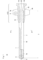
- FIG. 1 is a plan view of the catheter according to the first embodiment of the present invention.
- FIG. 2 is a cross-sectional view taken along the line AA'of the shaft of FIG.
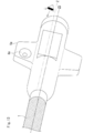
- FIG. 3 is an enlarged perspective view of the catheter and the hand portion of the first embodiment.
- FIG. 4 is an enlarged perspective view when the catheter of the first embodiment and the long axis of the hand portion are rotated by 180 ° about the central axis.
- FIG. 5 is a schematic cross-sectional view of blood vessels in the lower limbs.
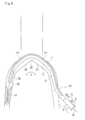
- FIG. 6 is a schematic cross-sectional view showing how the catheter of the first embodiment advances with the highly lubricated surface toward the outer inner surface of the curved blood vessel.
- FIG. 7 is a schematic cross-sectional view showing how the catheter of the first embodiment is placed with the low lubrication surface facing the outer inner surface of the curved blood vessel.
- FIG. 8 is a schematic cross-sectional view showing how the catheter of the first embodiment retracts with the highly lubricated surface toward the medial inner surface of the curved blood vessel.
- FIG. 9 is an enlarged perspective view of a hand portion according to a second embodiment of the present invention.
- FIG. 10 is an enlarged perspective view of a hand portion according to a first modification of the second embodiment of the present invention.
- FIG. 11 is an enlarged perspective view of a hand portion according to a modification 2 of the second embodiment of the present invention.
- FIG. 12 is an enlarged perspective view of a hand portion according to a modification 3 of the second embodiment of the present invention.
- FIG. 13 is an enlarged perspective view of a hand portion according to a third embodiment of the present invention.
- FIG. 14 is an enlarged perspective view of the side opposite to the central axis along the long axis of the hand portion according to the third embodiment of the present invention.
- FIG. 15 is a flowchart showing the steps of the treatment method of the present invention.
- “advance” means advancing the catheter from the blood vessel insertion port to the target site
- “backward” means returning the catheter to the blood vessel insertion port, that is, the hand side
- “indwelling” means inserting the catheter into the blood vessel. It means to fix it as it is.
- “Place on the outer surface at different positions” means to place the two elements on the outer surface of the catheter or hand without overlapping.
- the catheter 10 of the present embodiment shown in FIG. 1 is configured as a guiding sheath that conveys a treatment device (medical instrument) such as a balloon catheter, a stent installation catheter, and various embolic materials to a target site of a blood vessel. ing.
- a treatment device such as a balloon catheter, a stent installation catheter, and various embolic materials
- the catheter 10 includes a shaft 3, a soft tip 8 provided at the tip of the shaft 3, and a hub 5 as a hand portion 4 provided at the base end of the shaft 3.
- the shaft 3 is made of a flexible tubular body, and a shaft lumen (chamber) 9 is formed in the center of the shaft 3 over the entire length of the shaft 3.
- the shaft lumen 9 is opened at the opening at the tip of the soft tip 8.
- the catheter 10 is inserted into a blood vessel as a catheter assembly in which a hemostatic valve (not shown) is attached to a shaft 3 and a hub 5 and a dilator (not shown) is inserted.
- the dilator is withdrawn from the hub 5 and shaft 3 before inserting the treatment device into the catheter 10.
- the hemostatic valve may be left on or removed if necessary.
- the hub 5 has a hub tip portion 5c for fixing the shaft 3 inside, and the shaft 3 is fixed by insert molding.
- the hub 5 has a hub blue men 5f that opens at its base end and communicates with the inside of the shaft lumen 9.
- a long object such as a guide wire, a dilator, a catheter, an endoscope, an ultrasonic probe, and a temperature sensor can be inserted into the hub 5.
- various liquids such as a contrast medium, a chemical solution, and a physiological saline can be injected into the hub 5.
- the shaft 3 may be adhesively fixed in a lumen provided at the hub tip portion 5c of the hub 5 prepared as a separate member.
- the shaft 3 has a high lubrication surface 1 and a low lubrication surface on the outer surface at least a part of the outer surface along the long axis direction at the same position in the long axis direction of the shaft 3 but at different positions on the circumference. 2 is placed.
- the high lubrication surface 1 is a surface having a small frictional resistance with respect to the inner surface of the blood vessel, and is coated with a hydrophilic or hydrophobic lubricating resin provided on the outer surface of the shaft 3, or embossed on the outer surface. It is a product that has been processed to give unevenness. More specifically, the frictional resistance to the blood vessel is smaller than that of the outer surface of the uncoated or unprocessed shaft 3 near the base end of the catheter.
- the high lubrication surface 1 is formed in a planar shape along the long axis of the shaft 3.
- the shape of the highly lubricated surface 1 is not limited to a planar shape, and if the frictional resistance to the blood vessel is small, the lubricating resin or the embossed surface is separated and arranged in a plurality of linear lines, or a dotted line. , Or a collection of dots.
- a plurality of high lubrication surfaces 1 may be provided on the outer surface at different positions on the circumference of the shaft 3.
- the high lubrication surface 1 is made of a material that absorbs moisture and exhibits lubricity.
- the thickness of the lubricating layer can be appropriately set within a range in which sufficient lubricity can be obtained, and can be, for example, in the range of about 0.0001 mm to 0.02 mm.
- the hydrophilic polymer constituting the highly lubricated surface 1 include polyvinylpyrrolidone, polyvinyl alcohol, polyethylene oxide polymer, cellulosic polymer, acrylamide polymer, hyaluronic acid, polyacrylic acid, maleic anhydride polymer, and water-soluble polymer. Examples include sex nylons and derivatives thereof.
- these hydrophilic polymers are preferably crosslinked by adding an appropriate amount of a crosslinking agent or introducing an appropriate reactive functional group in order to firmly immobilize the surface of the outer layer 32.
- the tip portion 3a of the shaft 3 is not provided with the low lubrication surface 2, and only the high lubrication surface 1 is provided on the entire outer surface. This makes it easier for the catheter 10 to move through the bent blood vessel.
- the low lubrication surface 2 refers to a surface having a large frictional resistance to the inner surface of the blood vessel, and includes an uncoated or unprocessed outer surface of the catheter.
- a polymer having a photocurable functional group is applied to the entire outer surface of the shaft 3, a part is crosslinked, and then a part is masked and the non-masking part is further irradiated with light to crosslink. May be formed to form a low lubrication surface 2 having a larger frictional resistance than the masked portion.
- the masking portion may be a high lubrication surface 1 having a small frictional resistance.
- the shape of the low lubrication surface 2 is not limited to a planar shape, and the frictional resistance is larger than that of the high lubrication surface 1 such as a plurality of linearly spaced lines, a dotted line, or an aggregate of dots. Anything is fine. Alternatively, a plurality of them may be provided at different positions on the circumference.
- the portion is 0 to 500 mm, preferably 50 to 250 mm in the direction from the base end of the shaft to the tip end, and includes a portion composed of only the low lubrication surface 2 without providing the high lubrication surface 1.
- the catheter can also prevent the introducer and combined device from coming out of the hemostatic valve or penetration.
- the shaft 3 may be a single-layer resin tube, but as shown in the cross section AA'in FIG. 2, the shaft 3 has an inner layer 31 and an outer layer 32 in part, and a coil winding or a reinforcing wire of a blade structure is formed between the outer layers 32. It may have 33.
- the ratio of the length L1 of the high lubrication surface 1 and the length L2 of the low lubrication surface 2 to the entire circumference L1 + L2 may be arbitrary, but the ratio of the length of the high lubrication surface 1 on the circumference (L1 / L1 + L2) is It is 10 to 90%, more preferably 25 to 75%.
- the hub 5 has a hub tip portion 5c, a hub body portion 5d, a hub opening 5e, and a hub lumen 5f.
- the hub 5 is provided with a pair of wings 5a and 5b on the side surface, and the wing 5a has a marker 6 formed of a non-penetrating recess. It should be noted that the number of wings may be one, three or more, or not provided, instead of a pair (two).
- the marker 6 may be any one that can be recognized by sight, touch or perception such as shape, color, characters, symbols, surface irregularities or a combination thereof, and more preferably one that can be recognized by a plurality of senses.
- the ratio of L1 of the high lubrication surface 1 and the position and ratio of the color indicating the high lubrication surface 1 at the hand are made the same, or the hub on the high lubrication surface 1 side and the hub on the low lubrication surface 2 side are formed by two-color molding. You may change the color of the hub.
- the operator can visually recognize the position of the high lubrication surface 1 by the marker 6 and recognize the position of the high lubrication surface 1 of the catheter 10 in contact with the blood vessel.
- the marker 6 is located on the extension line Z extending along the long axis from the highly lubricated surface 1 provided on the shaft 3.
- the position of the highly lubricated surface 1 can be recognized at a glance by visually confirming the position of the marker 6.
- the position of the marker 6 can be confirmed by grasping the hub 5 and rotating the marker 6 with respect to the central axis Z2 along the long axis.
- the high lubrication surface 1 or the low lubrication surface 2 of the catheter 10 can be arranged at the position to be.
- the marker 6 is provided on the wing 5a provided on the hub 5, the position of the high lubrication surface 1 can be easily recognized by visually confirming the position of the wing 5a.
- the marker 6 since the marker 6 has a concave shape, the position of the highly lubricated surface 1 can be recognized by touch regardless of the visual sense. Therefore, it is not necessary to look at the hand portion 4 every time the operation is performed, which is more preferable because the procedure time can be shortened.
- the concave marker 6 is formed by transferring the gate mark or the shape of the gate when the hub 5 is injection-molded, so that the cost and time for separately providing the marker 6 can be shortened.
- the high lubrication surface 1 can be arranged on the side in contact with the blood vessel when advancing or retreating in the curved blood vessel Y, so that the frictional resistance with respect to the inner surface of the blood vessel can be reduced.
- the catheter 10 is placed to operate a treatment device (for example, a balloon catheter 11 described later)
- the low lubrication surface 2 is arranged on the side in contact with the blood vessel to prevent kickback of the catheter 10 due to the device operation. it can.
- the marker 6 may indicate the position of the low lubrication surface 2. As shown in FIG. 4, when the shaft 3 is inserted into the body, when the hub 5 is rotated by 180 ° about the central axis Z2 along the long axis, the position of the marker 6 is first with respect to the central axis Z2. Place it in the position opposite to the position of. In that case, the high lubrication surface 1 or the low lubrication surface 2 in the body is also arranged at the opposite positions.
- the catheter 10 operates as shown in FIGS. 5 to 8 below.
- This catheter 10 is introduced from, for example, one common femoral artery of the lower limb blood vessel shown in FIG. 5, and is placed across the aortic iliac artery bifurcation 24 and in front of the contralateral common femoral artery (contralateral puncture). ) Used in the method.
- the catheter 10 may be a guiding catheter, an introducer sheath, a contrast catheter, a microcatheter, or a guide wire support catheter. Further, the catheter 10 may be a balloon catheter, a stent delivery catheter, an atherectomy catheter, or a diagnostic imaging catheter including a reinforcing body.
- a catheter 10 in which a dilator (not shown) and a guide wire 12 are inserted into a shaft lumen 9 by puncturing the left common femoral artery 23 by the Seldinger method is preceded by the guide wire 12 with respect to the tip of the catheter 10.
- the tip of the catheter 10 is inserted into the left common femoral artery 23.
- the catheter 10 may be inserted from the radial artery of the arm (not shown) instead of the left common femoral artery 23.
- the lower limb artery on the same side as the lesion may be punctured (ipsilateral puncture), and a guiding catheter or a guiding catheter combined with an internal catheter may be provided via an introducer sheath (not shown).
- the catheter assembly may be inserted into the vessel.
- the shaft 3 has a tip 3a or a base 3b or Both of them are elastically deformed and curved.
- the shaft 3 comes into contact with the outer inner surface Y1 of the curved blood vessel Y in an attempt to widen so that the radius of curvature becomes larger due to the restoring force against elastic deformation.
- the highly lubricated surface 1 of the catheter 10 When the highly lubricated surface 1 of the catheter 10 is arranged so as to face the outer inner surface Y1, most of the outer surface of the shaft 3 in contact with the inner surface of the blood vessel becomes the highly lubricated surface 1. Therefore, the frictional resistance generated between the catheter 10 and the inner surface of the blood vessel is about the same as that of a catheter provided with a highly lubricated surface on the entire outer surface of the shaft 3. Therefore, it is possible to determine that the catheter 10 is advanced in the curved blood vessel Y, confirm the position of the marker 6, and advance the catheter 10 in the curved blood vessel Y.
- a treatment step a determination is made to advance the catheter 10, the position of the marker 6 is confirmed, and the high lubrication surface 1 is arranged so as to face the outer inner surface Y1 of the curved blood vessel Y. recognize. Carefully push the hub 5 of the catheter 10 forward into the curved blood vessel Y1.
- the shaft 3 is not arranged in a state suitable for advancing.
- the operator rotates the hub 5 with respect to the central axis Z2 along the long axis to rotate the catheter 10.
- the catheter 10 is advanced.
- the balloon catheter 11 which is a treatment device, is inserted into the shaft lumen 9 of the catheter 10. Friction resistance may occur when the balloon catheter 11 passes through the stenosis X in the right external iliac artery 26. In this case, the position of the catheter 10 may shift due to the kickback of the catheter, which is a reaction of friction. When the position shift occurs, the surgeon temporarily removes the balloon catheter 11 in order to return the catheter 10 to the target site and temporarily suspends the procedure, which increases the procedure time.
- the operator decides to place the catheter 10 in the blood vessel.
- the position of the marker 6 is the highly lubricated surface 1 of the shaft 3. Recognizes that it is arranged facing the inner inner surface Y2 of the curved blood vessel Y, in other words, recognizes that the low lubrication surface 2 of the shaft 3 faces the outer inner surface Y1 of the curved blood vessel Y.
- the shaft 3 of the catheter 10 tends to expand outward due to the reaction of the frictional resistance between the narrowed portion X and the balloon catheter 11.
- the catheter 10 is less likely to kick back and is stably placed without being displaced from the target site.
- the catheter 10 when it is determined to place the catheter 10 as a treatment step, the position of the marker 6 is confirmed, and it is recognized that the low lubrication surface 2 faces the outer inner surface Y1 of the curved blood vessel Y. , The catheter 10 is placed in the blood vessel, and the balloon catheter 11 is inserted to treat the stenosis X.
- the hub 5 is placed along the major axis Z2.
- the catheter 10 is placed after recognizing that the low lubrication surface 2 is facing the outer inner surface Y1 after confirming the position of the marker 6 again by rotating the axis with respect to the lower lubrication surface 2 toward the outer inner surface Y1. You may let me.
- the frictional resistance generated between the catheter 10 and the inner surface of the blood vessel is about the same as that of a catheter provided with a highly lubricated surface on the entire outer surface of the catheter shaft.
- the catheter 10 can be retracted and removed with a small frictional resistance to the inside of the curved blood vessel Y.
- the hub 5 is rotated about the central axis Z2 along the long axis, and the catheter 10 is rotated with respect to the long axis.
- the catheter 10 is retracted, recognizing that the high lubrication surface 1 faces the inner inner surface Y2.
- the catheter 10 is removed from the body, necessary measures such as hemostasis are performed, and the treatment is completed.
- the tip 3a of the shaft 3 is retracted to the aortic iliac artery bifurcation 24, and then the catheter 10 is further placed on the lower limb on the opposite side. You may proceed with the treatment and continue the treatment.
- FIG. 9 shows a second embodiment in which the kink-resistant protector 7 and the hub 5 are provided on the hand portion 4. Since the shaft 3 and the hub 5 are the same as those in the first embodiment, the description thereof will be omitted.
- the kink-resistant protector 7 includes a flexible portion 7a having a flexible tip to prevent the catheter from kinking at hand, and a body portion 7b that protects the base end portion of the catheter and can be fitted with the tip end portion of the hub 5.
- characters are described as information indicating the high lubrication surface 1 on the extension line Z extending from the high lubrication surface 1 along the long axis.
- the kink-resistant protector 7 can be described in large characters, and can be easily recognized visually or perceptually.
- the character indicating the high lubrication surface 1 is used as the first marker 6a, and the second marker 6a'is placed on the outer surface of the kink-resistant protector 7 at a position opposite to the central axis Z2 along the long axis of the kink-resistant protector 7. Characters may be described as information indicating the low lubrication surface 2.
- the first marker 6a or the second marker 6a' can be confirmed even if the hub 5 is rotated about the central axis Z2 along the long axis to change the direction, so that the highly lubricated surface can be confirmed.
- the position of 1 or the low lubrication surface 2 can be visually or perceptually recognized.
- a concave marker 6b may be provided as the first marker on the wing of the hub 5, and the character 6b'may be described on the kink-resistant protector 7 as the second marker.
- the position of the highly lubricated surface 1 can be visually and tactilely recognized.
- a concave first marker 6c is provided on the wing 5a of the hub 5, and information indicating the position of the highly lubricated surface 1 is provided on the hub body portion 5d as the second marker 6c'. It may be described. This makes it possible to visually and perceptually recognize the highly lubricated surface 1.
- information indicating the position of the low lubrication surface 2 may be described on the hub body portion 5d as a marker 6d.
- a second marker 6d' may be provided on the opposite side of the central axis Z2 along the long axis of the hub 5 with respect to the first marker showing the highly lubricated surface 1 of the modified example 3. This makes it possible to prevent mistakes caused by the operator's beliefs.
- the kink-resistant protector and the hub may be integrated to reduce the number of parts.
- the position of the high lubrication surface can be quickly recognized visually, tactilely and perceptually with one marker, shortening the procedure time, or depending on the operator's belief. You can prevent mistakes.
- the marker 6e is provided on the wing 5a at a position away from the extension line Z extending from the high lubrication surface 1.
- the hub is visually recognized, it can be easily visually recognized because the orientations of the highly lubricated surface 1 of the shaft 3 and the markers 6e provided on the wings 5a are the same.
- the first marker 6f showing the high lubrication surface 1 and the low lubrication surface 2 showing the low lubrication surface 2 on the opposite side symmetrical with respect to the central axis Z2 along the long axis of the hand portion.
- the marker 6f'of 2 may be provided.
- the treatment method using a catheter according to the present invention has a shaft 3 having a tip and a proximal end, and a hand portion 4 attached to the proximal end of the shaft 3, and the shaft 3 is at least one of the outer surfaces.
- the high lubrication surface 1 and the low lubrication surface 2 are provided in the portion, and the high lubrication surface 1 and the low lubrication surface are on the outer surface at the same position along the long axis of the shaft 3 but at different positions on the circumference. 2 is arranged, the marker 6 is provided on the outer surface of the hand portion 4, and the marker 6 prepares a catheter 10 indicating the position of the high lubrication surface 1 or the low lubrication surface 2.
- the treatment method comprises a step of determining forward, backward, or indwelling of the catheter 10 and a step of confirming the position of the marker 6.
- the catheter 10 by confirming the position of the marker 6 on the hand portion 4 as shown in FIG. 15, when the catheter 10 is advanced or retracted, the catheter 10 has frictional resistance against the inner surface of the blood vessel in contact with the catheter 10.
- the catheter 10 can be moved in a small state. Therefore, the catheter 10 can be advanced and retracted in a short time without trial and error.
- the frictional resistance between the catheter 10 and the blood vessel is increased to prevent kickback, thereby preventing the catheter 10 from being displaced and shortening the operation time.
- a step of rotating the hand portion 4 with respect to the central axis Z2 along the long axis to rotate the catheter 10 with respect to the long axis may have steps to advance, retract or indwell the catheter after recognizing the position of surface 1.
- the highly lubricated surface 1 or the highly lubricated surface 1 or the direction suitable for advancing, retreating or indwelling the catheter 10 The low lubrication surface 2 can be arranged to select a state of high frictional resistance and a state of low frictional resistance, and then the catheter 10 can be advanced, retracted or indwelled.
- the low lubrication surface 2 may be composed of a region in which the lubrication performance is deteriorated by forming the film thickness of the high lubrication surface 1 thinner than the others. Further, the low lubrication surface 2 may be covered with a material having a higher coefficient of friction than the material constituting the high lubrication surface 1.
Landscapes
- Health & Medical Sciences (AREA)
- Life Sciences & Earth Sciences (AREA)
- Biophysics (AREA)
- Pulmonology (AREA)
- Engineering & Computer Science (AREA)
- Anesthesiology (AREA)
- Biomedical Technology (AREA)
- Heart & Thoracic Surgery (AREA)
- Hematology (AREA)
- Animal Behavior & Ethology (AREA)
- General Health & Medical Sciences (AREA)
- Public Health (AREA)
- Veterinary Medicine (AREA)
- Media Introduction/Drainage Providing Device (AREA)
Abstract
【課題】湾曲血管内でのカテーテルの前進、後退または留置を容易にし、処置用デバイスの操作時のキックバックによる位置ずれを防止して、適切に留置できるカテーテルを提供する。 【解決手段】 シャフト3の長軸方向の同一位置で、円周上異なる位置の外表面に高潤滑面1と、高潤滑面1より摩擦抵抗の大きい低潤滑面2を配置し、手元部のマーカー6によって高潤滑面1の位置を示し、前進、または後退の際の血管と接する側に高潤滑面1を配置して、摩擦抵抗が小さくして前進、後退を容易にする。血管内にカテーテル10を留置するときは、血管と接する側に低潤滑面2を配置して摩擦抵抗を大きくして、処置デバイス11の操作によるキックバックを防止し、カテーテル10の操作を容易にして手術が容易かつ、短時間で完了することができる。また、イントロデューサーや併用デバイスが止血弁や穿通部からのカテーテルが抜けることを防止することができる。
Description
本発明は、生体管腔内に挿入されるカテーテル、およびカテーテルを用いた治療方法に関する。
血管等の生体管腔へ医療器具を挿入して行う診断や治療が広く実施されている。このような診断や治療には、例えばバルーンカテーテル等の処置用デバイスを目的部位に導く導入用カテーテルが用いられている。導入用カテーテルは、処置用デバイスの外径よりも大きな内径を有する平滑な内腔を有しており、処置用デバイスの使用に先立って生体管腔内に挿入される。
導入用カテーテルには、生体管腔との摩擦抵抗を減らすべく、外面が、親水性ポリマー等の潤滑性を有する材料でコーティングされた高潤滑面が設けられている。
特許文献1には、湾曲したカテーテルの湾曲内側に、潤滑性の低い低潤滑面を設け、湾曲外側に高潤滑面を設けたカテーテルが記載されている。
狭窄した病変部を治療するために、カテーテルを血管内に配置して、カテーテルルーメン内にバルーンカテーテルなどの処置用デバイスを通して、狭窄した病変部に配置する場合がある。狭窄した病変部を通過する際に、バルーン拡張部が病変部で大きな摩擦抵抗を生じ、その摩擦抵抗の反作用により、バルーンカテーテルが押し戻されると、バルーンカテーテル外面とカテーテル内面が接触してカテーテル自体が手元側に押し戻される。この現象をキックバックという。
一方、カテーテルの高潤滑面が体内でどちらを向いているかは、X線造影などでは判別できないため、手感覚で時間をかけて試行錯誤しながらカテーテルを前進、後退、回転を繰り返し、カテーテルの導入あるいは留置を行う場合が多い。
本発明は、キックバックを防ぎながら手技時間を短縮してカテーテルを血管内に導入あるいは留置するために、使用時に高潤滑面の向きを容易に判別できるカテーテルと、そのカテーテルを用いた治療方法を提供することを目的とする。
また、カテーテルは、イントロデューサーや併用デバイスが止血弁や穿通部から抜けることを防止することができる。
前記の目的を達成するのは、以下の本発明である。
(1)先端と基端を有するシャフトと、前記シャフトの基端に取り付けられた手元部とを有し、前記シャフトは、外表面と、前記外表面の少なくとも一部に高潤滑面および低潤滑面を有し、前記高潤滑面および前記低潤滑面は、前記シャフトの長軸に沿って同一位置であって、円周上異なる位置の外表面に配置され、前記手元部は、手元部外表面の少なくとも一部にマーカーを有し、前記マーカーが前記高潤滑面または、前記低潤滑面の位置を示す、ことを特徴とするものである。
(2)前記マーカーが、前記高潤滑面から、長軸に沿って伸ばした延長線上に配置された上記(1)のカテーテルである。
(3)前記手元部がハブである上記(1)または(2)のカテーテルである。
(4)前記マーカーが、前記ハブの側面に設けられたウイングに設けられた上記(1)~(3)のいずれかのカテーテルである。
(5)前記マーカーが、凹形状である上記(1)~(4)のいずれかのカテーテルである。
(6)前記手元部が耐キンクプロテクターを有する上記(1)~(5)のいずれかのカテーテルである。
(7)前記マーカーが前記高潤滑面を示す情報を有する上記(1)~(6)のいずれかのカテーテルである。
(8)前記マーカーを第1のマーカーとし、前記第1のマーカーと異なる位置の前記手元部外表面に、第2のマーカーを有する上記(1)~(7)のいずれかのカテーテルである。
(9)前記第2のマーカーが前記第1のマーカーに対して前記手元部の長手方向の中心軸を対称軸として反対側の前記手元部外表面に配置された上記(8)のカテーテルである。
(10)前記マーカーが、前記高潤滑面から、長軸に沿って伸ばした延長線上と異なる位置の前記手元部外表面に配置された上記(1)のカテーテルである。
(11)本発明に係るカテーテルを用いた治療方法は、先端と基端を有するシャフトと、前記シャフトの基端に取り付けられた手元部とを有し、前記シャフトは、外表面と、前記外表面の少なくとも一部に高潤滑面および低潤滑面を有し、前記高潤滑面および前記低潤滑面は、前記シャフトの長軸に沿って同一位置であって、円周上異なる位置の外表面に配置され、前記手元部は、手元部外表面の少なくとも一部にマーカーを有し、前記マーカーが前記高潤滑面または、前記低潤滑面の位置を示す、ことを特徴とするカテーテルを用意するステップと、前記カテーテルの前進、後退または留置を判断するステップと、前記マーカーの位置を確認するステップと、前記マーカーの位置により前記高潤滑面および前記低潤滑面の向きを認識するステップと、前記カテーテルを前進、後退または留置するステップと、を有する、ことを特徴とする治療方法である。
(12)前記治療方法は、前記カテーテルを用意するステップと、前記手元部の長手方向の中心軸に対して軸回転させて、前記カテーテルを長軸に対して軸回転するステップと、前記マーカーの位置を確認するステップと、前記マーカーの位置により前記高潤滑面の向きを認識するステップと、前記カテーテルを前進、後退または留置するステップと、を有する上記(11)の治療方法である。
本発明に係るカテーテル及びその治療方法によれば、シャフトの外表面に高潤滑面と低潤滑面を有し、前記高潤滑面と前記低潤滑面がシャフトの長軸方向の同一位置で、円周上異なる位置の外表面に血管内面に対する摩擦抵抗が小さい高潤滑面と、血管内面に対する摩擦抵抗が大きい低潤滑面を配置し、手元部のマーカーによって高潤滑面の位置を示し、前進、または後退の際の血管内面と接する側に高潤滑面を配置して、カテーテル外表面と血管内面との摩擦抵抗を小さくしてカテーテルの前進、後退を容易にする。カテーテルを留置するときは、血管内面と接する側に低潤滑面を配置して摩擦抵抗を大きくして、処置デバイスの操作によるキックバックを防止し、カテーテルの操作を容易にして手術が容易かつ、短時間で完了することができる。
また、カテーテルは、イントロデューサーや併用デバイスが止血弁や穿通部から抜けることを防止することができる。
以下、本発明の好適な実施形態を挙げ、添付の図面を参照して詳細に説明する。なお、図面の寸法比率は、説明の都合上、誇張されて実際の比率とは異なる場合がある。また、以下の説明において、カテーテルの手元側を「基端」、生体内へ挿入される側を「先端」と呼ぶ。
また、「前進」とは、血管挿入口からカテーテルを目的部位へ進めること、「後退」とは、カテーテルを血管挿入口すなわち手元側へ戻すこと、「留置」とは、カテーテルを血管に挿入したまま固定しておくことをいう。
「異なる位置の外表面に配置する」とは、カテーテルまたは手元部の外表面において二つの要素を重ねずに配置することをいう。
(第1実施形態)
図1に示す本実施形態のカテーテル10は、例えば、バルーンカテーテル、ステント設置用カテーテル及び各種塞栓材等の処置用デバイス(医療器具)を、血管の目的部位にまで搬送するガイディングシースとして構成されている。
図1に示す本実施形態のカテーテル10は、例えば、バルーンカテーテル、ステント設置用カテーテル及び各種塞栓材等の処置用デバイス(医療器具)を、血管の目的部位にまで搬送するガイディングシースとして構成されている。
カテーテル10は、シャフト3と、シャフト3の先端に設けられたソフトチップ8と、シャフト3の基端に設けられた手元部4として、ハブ5とを備えている。
シャフト3は、可撓性を有する柔軟な管体よりなり、その中心部にシャフト3の全長にわたってシャフトルーメン(内腔)9が形成されている。シャフトルーメン9は、ソフトチップ8の先端の開口部で開放している。このカテーテル10は、シャフト3及びハブ5に止血弁(図示せず)を取り付け、ダイレータ(図示せず)を挿入したカテーテル組立体として、血管に挿入される。ダイレータは、カテーテル10に処置用デバイスを挿入する前にハブ5及びシャフト3から引き抜かれる。止血弁はつけたままでもよく、必要に応じて取り外してもよい。
図1において、部分断面図で内部構造を示すとおり、ハブ5は内部にシャフト3を固定するハブ先端部5cを有し、シャフト3がインサート成型により固定されている。そしてハブ5は、その基端に開口するハブルーメン5fを有し、シャフトルーメン9の内部と連通する。このハブ5には、例えば、ガイドワイヤ、ダイレータ、カテーテル類、内視鏡、超音波プローブ、温度センサー等の長尺物を挿入することができる。またハブ5には、造影剤、薬液、生理食塩水等の各種液体等を注入することもできる。
シャフト3は、別部材として用意されたハブ5のハブ先端部5cに設けられたルーメン内に接着固定されてもよい。
シャフト3は、長軸方向に沿って外表面の少なくとも一部に、前記シャフト3の長軸方向の同一位置であって、円周上異なる位置の外表面に高潤滑面1と、低潤滑面2が配置される。
本明細書において、高潤滑面1とは、血管内面に対する摩擦抵抗が小さい面であり、シャフト3の外面に設けられた、親水性あるいは疎水性の潤滑性樹脂のコーティング、または外表面にエンボスなど凹凸付与の加工が施されたものをいう。より具体的には、カテーテル基端近傍の未コーティングあるいは、未加工であるシャフト3の外表面より血管に対する摩擦抵抗が小さいものである。
高潤滑面1は、シャフト3の長軸に沿って面状に形成されている。なお、高潤滑面1の形状は面状に限定されるものではなく、血管に対する摩擦抵抗が小さければ、潤滑性樹脂やエンボス加工された表面が離間して複数の線状に並んだもの、点線、あるいはドットの集合体でもよい。
高潤滑面1は、シャフト3の円周上異なる位置の外表面に複数設けられてもよい。
高潤滑面1は、親水性ポリマーを用いる場合、水分を吸収して潤滑性を発揮する材料よりなる。潤滑層の厚さは、十分な潤滑性が得られる範囲で適宜設定できるが、例えば、0.0001mm~0.02mm程度の範囲とすることができる。また、高潤滑面1を構成する親水性ポリマーとしては、例えば、ポリビニルピロリドン、ポリビニルアルコール、ポリエチレンオキシド系ポリマー、セルロース系ポリマー、アクリルアミド系ポリマー、ヒアルロン酸、ポリアクリル酸、無水マレイン酸系ポリマー、水溶性ナイロン及びそれらの誘導体が挙げられる。また、これらの親水性ポリマーは、外層32の表面に強固に固定化するために、適量の架橋剤の添加あるいは、適切な反応性官能基の導入により架橋させたものであることが好ましい。
本実施形態では、シャフト3の先端部3aは、低潤滑面2を設けず、高潤滑面1のみが外表面全周に設けられている。これにより、カテーテル10は屈曲した血管内を進みやすくなる。
また、低潤滑面2とは、血管内面に対する摩擦抵抗が大きいものをいい、未コーティングあるいは、未加工のカテーテル外表面も含む。
あるいは、光硬化型官能基を有するポリマーをシャフト3の外表面全周に塗布し、一部を架橋したのちに、一部をマスキングして、非マスキング部にさらに光を照射することで、架橋を促進させてマスキングされた部分よりも摩擦抵抗の大きい低潤滑面2を形成してもよい。この場合、マスキング除去後マスキング部を摩擦抵抗の小さい高潤滑面1としてもよい。
あるいは、光硬化型官能基を有するポリマーをシャフト3の外表面全周に塗布し、一部を架橋したのちに、一部をマスキングして、非マスキング部にさらに光を照射することで、架橋を促進させてマスキングされた部分よりも摩擦抵抗の大きい低潤滑面2を形成してもよい。この場合、マスキング除去後マスキング部を摩擦抵抗の小さい高潤滑面1としてもよい。
なお、低潤滑面2の形状は面状に限定されるものではなく、離間して複数の線状に並んだもの、点線、あるいはドットの集合体など、高潤滑面1よりも摩擦抵抗が大きいものであればよい。あるいは、円周上異なる位置に離れて複数設けられてもよい。
なお、本実施形態ではシャフト基端から先端方向に0~500mm、好ましくは50~250mmで、高潤滑面1を設けずに低潤滑面2のみで構成される部位を含んでいる。これにより術者がシャフト3を把持する際に、手が滑ることなく操作しやすい。また、カテーテルは、イントロデューサーや併用デバイスが止血弁や穿通部から抜けることを防止することができる。
シャフト3は単層の樹脂チューブでもよいが、図2にその断面A-A’を示すように一部に内層31と外層32と有し、外層32の間にコイル巻きまたはブレード構造の補強線33を有してもよい。
全円周L1+L2に対する高潤滑面1の長さL1および低潤滑面2の長さL2の割合は、任意でよいが、円周上の高潤滑面1の長さの割合(L1/L1+L2)が10から90%、より好ましくは25から75%である。
次に、図3の手元部4としてのハブ5を説明する。ハブ5は、ハブ先端部5c、ハブ胴体部5d、ハブ開口部5eおよびハブルーメン5fを有する。ハブ5は、側面に一対のウイング5aとウイング5bを設けられ、ウイング5aには非貫通の凹部からなるマーカー6を有する。なお、ウイングは一対(2個)ではなく、1個あるいは3つ以上あってもよく、あるいは設けなくともよい。
マーカー6は、形状、色、文字、記号、表面の凹凸あるいはこれらの組み合わせなどの視覚、触覚あるいは知覚により認識できるものであればよく、複数の感覚で認識できるものであればより好ましい。
マーカーの付与方法として、印刷、刻印、成形、加工、化学反応、レーザーマーキングあるいはこれらを組み合わせてもよい。また、高潤滑面1のL1の割合と手元部の高潤滑面1を示す色の位置および割合を同一にする、あるいは、2色成形により高潤滑面1側のハブと低潤滑面2側のハブの色を変えてもよい。
術者は、マーカー6により視覚で高潤滑面1の位置を認識し、血管と接触するカテーテル10の高潤滑面1の位置を認識することができる。
また、マーカー6は、シャフト3上に設けられた高潤滑面1から長軸に沿って延長した延長線Z上に位置している。
上記のカテーテル10は、マーカー6の位置を視覚で確認することで、高潤滑面1の位置が一目で認識できる。
また、マーカー6は、ハブ5に設けられることで、ハブ5を把持して、長軸に沿った中心軸Z2に対して軸回転させながら、マーカー6の位置を確認すれば、血管内の目的とする位置にカテーテル10の高潤滑面1あるいは低潤滑面2を配置することができる。
さらに、マーカー6が、ハブ5に設けられたウイング5aに設けられることで、ウイング5aの位置を視覚で確認すれば、高潤滑面1の位置を容易に認識することができる。
さらに、マーカー6が凹形状であるため、視覚に依らず、触感で高潤滑面1の位置を認識できる。そのため、操作のたびに手元部4を見る必要がないため、手技時間が短縮できるのでより好ましい。
さらに凹形状であるマーカー6は、ハブ5を射出成型したときのゲート痕あるいはゲートの形状を転写して形成することで、マーカー6を別途設けるコストと時間を短縮することができる。
上記のカテーテル10は、湾曲血管Y内で、前進、または後退の際に血管と接する側に高潤滑面1を配置して、血管内面に対する摩擦抵抗が小さくできる。処置用デバイス(例えば、後述するバルーンカテーテル11)を操作するためにカテーテル10を留置するときは、血管と接する側に低潤滑面2を配置することで、デバイス操作によるカテーテル10のキックバックを防止できる。
なお、マーカー6は、低潤滑面2の位置を示すものでもよい。
図4に示すように、シャフト3を体内に挿入したときに、ハブ5を長軸に沿った中心軸Z2を中心に180°軸回転させると、マーカー6の位置が中心軸Z2に対して最初の位置と反対の位置に配置する。その場合、体内での高潤滑面1または低潤滑面2も反対の位置に配置される。
図4に示すように、シャフト3を体内に挿入したときに、ハブ5を長軸に沿った中心軸Z2を中心に180°軸回転させると、マーカー6の位置が中心軸Z2に対して最初の位置と反対の位置に配置する。その場合、体内での高潤滑面1または低潤滑面2も反対の位置に配置される。
これによって、マーカー6の位置を確認することで各潤滑面1、2の向きを認識することができる。
本実施形態に係るカテーテル10は、以下図5から図8に示すように作用する。
このカテーテル10は、例えば図5に示す下肢血管の一方の総大腿動脈から導入され、大動脈腸骨動脈分岐部24を越えて、反対側の総大腿動脈手前に配置されるクロスオーバー(対側穿刺)法に用いられる。
このカテーテル10は、例えば図5に示す下肢血管の一方の総大腿動脈から導入され、大動脈腸骨動脈分岐部24を越えて、反対側の総大腿動脈手前に配置されるクロスオーバー(対側穿刺)法に用いられる。
なお、カテーテル10は、ガイディングシース以外に、ガイディングカテーテル、イントロデューサーシース、造影カテーテル、マイクロカテーテル、ガイドワイヤサポートカテーテルであってもよい。また、カテーテル10は、補強体を含んだ、バルーンカテーテル、ステントデリバリーカテーテル、アテレクトミーカテーテル、画像診断カテーテルであってもよい。
セルジンガー法により、左総大腿動脈23に穿刺し、シャフトルーメン9にダイレータ(図示せず)とガイドワイヤー12を挿入した状態のカテーテル10を、カテーテル10の先端に対してガイドワイヤー12を先行させた状態で、カテーテル10の先端を、左総大腿動脈23内へ挿入する。なお、カテーテル10は、左総大腿動脈23ではなく腕の橈骨動脈(図示せず)から挿入されてもよい。
あるいは、病変部と同じ側の下肢動脈に穿刺(同側穿刺)してもよく、イントロデューサーシース(図示せず)を介して、ガイディングカテーテルあるいは、ガイディングカテーテルと内カテーテルを組み合わせたガイディングカテーテル組立体を血管に挿入してもよい。
図6に示すように、左総腸骨動脈21、大動脈腸骨動脈分岐部24および右総腸骨動脈25にかけて湾曲血管Y内にカテーテル10を配置すると、シャフト3は先端部3aまたは基部3bあるいはその両者が弾性変形して湾曲する。
湾曲血管Y内でシャフト3は、弾性変形に対する復元力により湾曲半径が大きくなるように広がろうとして、湾曲血管Yの外側内面Y1と接触する。
カテーテル10の高潤滑面1は外側内面Y1を向いて配置されると、血管内面と接するシャフト3の外表面の大部分は高潤滑面1となる。そのため、カテーテル10と血管内面の間に生じる摩擦抵抗は、シャフト3の外表面全面に高潤滑面を設けたカテーテルと同程度となる。そこで、カテーテル10を湾曲血管Y内で前進する判断を行い、マーカー6の位置を確認して、カテーテル10を湾曲血管Y内に前進させることができる。
本発明の治療方法において、治療ステップとして、カテーテル10を前進する判断を行い、マーカー6の位置を確認して、高潤滑面1が湾曲血管Yの外側内面Y1を向いて配置されていることを認識する。カテーテル10のハブ5を慎重に押し込んで湾曲血管Y1内を前進させる。
マーカー6が、カテーテル10の低潤滑面2が外側内面Y1を向いて配置されていることを示す場合は、シャフト3の向きが前進に適した状態で配置されていない。この時、術者はハブ5を長軸に沿った中心軸Z2に対して軸回転させて、カテーテル10を軸回転させる。マーカー6の位置を確認し、高潤滑面1が外側内面Y1を向いて配置されていること認識した後に、カテーテル10を前進させる。
次に、カテーテル10を血管内に留置させる場合について説明する。図7に示すように、カテーテル10のシャフトルーメン9内に、処置用デバイスであるバルーンカテーテル11を挿入する。バルーンカテーテル11は、右外腸骨動脈26にある狭窄部Xを通過させる際に、摩擦抵抗が生じる場合がある。この場合、摩擦の反作用であるカテーテルのキックバックにより、カテーテル10の位置ずれが生じる場合がある。術者は位置ずれが生じると、カテーテル10を目的部位に戻すためバルーンカテーテル11を一旦抜去して、手技を一時中断するため、手技時間が長くなる。
そのため、バルーンカテーテル11を進める場合、術者はカテーテル10を血管内に留置することを判断する。ハブ5のマーカー6の位置を確認して、ハブ5を把持してハブ5の長軸に沿った中心軸Z2を中心に軸回転させたあと、マーカー6の位置はシャフト3の高潤滑面1が、湾曲血管Yの内側内面Y2を向いて配置されることを認識する、言い換えるとシャフト3の低潤滑面2が湾曲血管Yの外側内面Y1を向いていることを認識する。
この時、カテーテル10は、バルーンカテーテル11を進めると、狭窄部Xとバルーンカテーテル11との摩擦抵抗の反作用によりシャフト3が外側に拡がろうとする。
この場合、血管内面と接するシャフト3の外表面の大部分が低潤滑面2となる。そのため、カテーテル10の外表面と血管内面の間に生じる摩擦抵抗は、カテーテルシャフトの外表面全面が低潤滑面であるカテーテルと同程度となる。
これにより、カテーテル10は、キックバックが起こりにくくなり、目的部位から位置ずれすることなく安定して留置される。
本発明の治療方法において、治療ステップとして、カテーテル10を留置する判断をした場合、マーカー6の位置を確認して、低潤滑面2が湾曲血管Yの外側内面Y1を向いていることを認識し、カテーテル10を血管内に留置して、バルーンカテーテル11を挿入して狭窄部Xを治療する。
マーカー6の位置が、シャフト3の向きが留置に適した位置ではない場合、すなわち高潤滑面1が外側内面Y1を向いて配置されている場合は、ハブ5を長軸に沿った中心軸Z2に対して軸回転させて、低潤滑面2を外側内面Y1に向け、改めてマーカー6の位置を確認した後に、低潤滑面2が外側内面Y1に向いていることを認識してカテーテル10を留置させてもよい。
最後に、狭窄部Xの治療後、カテーテル10を後退させる場合について説明する。
図8に示すように、カテーテル10の手元部4を引っ張ると、前進させる場合とは逆にシャフト3の湾曲半径が小さくなるように変形する。そのため内側内面Y2とシャフト3が接触する場合がある。この場合、シャフト3の高潤滑面1を内側内面Y2に向けると、シャフト3の長軸方向に設けられた高潤滑面1が、内側内面Y2と接触する。
これにより、カテーテル10は、内側内面Y2と接するシャフト3の大部分が高潤滑面1となる。そのため、カテーテル10と血管内面の間に生じる摩擦抵抗は、カテーテルシャフトの外表面全面に高潤滑面を設けたカテーテルと同程度となる。カテーテル10は、湾曲血管Y内に対する摩擦抵抗が小さくして後退させて抜去することができる。
本発明の治療方法において、マーカー6が、シャフト3の向きが後退に適していない場合は、ハブ5を長軸に沿った中心軸Z2に対して軸回転させて、カテーテル10を長軸に対して回転し、マーカー6を確認後に、高潤滑面1が内側内面Y2を向いていることを認識して、カテーテル10を後退させる。
その後、カテーテル10を使用する必要がなければ、カテーテル10を体外に抜去し、止血など必要な処置を行って、治療を終了する。
あるいは、腕の動脈から挿入した場合、反対側の下肢に病変部があれば、シャフト3の先端部3aを大動脈腸骨動脈分岐部24まで後退させた後、さらに、反対側の下肢にカテーテル10を進めてそのまま続けて治療を行ってもよい。
(第2実施形態)
図9に、手元部4に耐キンクプロテクター7およびハブ5が設けられた第2実施形態を示す。シャフト3とハブ5は、第1実施形態と同様であるため、説明を省略する。耐キンクプロテクター7は、先端が柔軟でカテーテルが手元でキンクすることを防止する柔軟部7aとカテーテルの基端部を保護し、ハブ5の先端部と嵌合可能な胴体部7bを備える。
図9に、手元部4に耐キンクプロテクター7およびハブ5が設けられた第2実施形態を示す。シャフト3とハブ5は、第1実施形態と同様であるため、説明を省略する。耐キンクプロテクター7は、先端が柔軟でカテーテルが手元でキンクすることを防止する柔軟部7aとカテーテルの基端部を保護し、ハブ5の先端部と嵌合可能な胴体部7bを備える。
本実施形態では、高潤滑面1から長軸に沿って延長した延長線Z上に高潤滑面1を示す情報として文字が記載されている。耐キンクプロテクター7は、ハブ5に比べ、大きな文字で記載が可能であり、視覚あるいは知覚により認識しやすくなる。
さらに高潤滑面1を示す文字を第1のマーカー6aとして、耐キンクプロテクター7の長軸に沿った中心軸Z2を中心に反対の位置の耐キンクプロテクター7の外表面に第2のマーカー6a’として低潤滑面2を示す情報として文字を記載してもよい。
これにより、ハブ5を長軸に沿った中心軸Z2を中心に軸回転させて向きを変えても、第1のマーカー6aあるいは第2のマーカー6a’を確認することができるため、高潤滑面1または低潤滑面2の位置を視覚または知覚で認識できる。
あるいは図10に示す変形例1として、ハブ5のウイングに第1のマーカーとして凹形状であるマーカー6bを設け、第2のマーカーとして、耐キンクプロテクター7に文字6b’を記載してもよい。これにより、視覚と触覚で高潤滑面1の位置を認識することができる。
あるいは図11に示す変形例2として、ハブ5のウイング5aに凹形状の第1のマーカー6cを設け、第2のマーカー6c’として、ハブ胴体部5dに高潤滑面1の位置を示す情報を記載してもよい。これにより視覚および知覚により高潤滑面1を認識することができる。
あるいは図12に示す変形例3として、ハブ胴体部5dにマーカー6dとして低潤滑面2の位置を示す情報を記載してもよい。あるいは、変形例3の高潤滑面1を示す第1のマーカーに対して、ハブ5の長軸に沿った中心軸Z2の反対側に第2のマーカー6d’として設けてもよい。これにより術者の思い込みによる間違いを防止することができる。
あるいは、耐キンクプロテクターとハブを一体とし、部品点数を少なくしてもよい。
あるいは凹形状に高潤滑面1を表す文字を印刷することで、1つのマーカーで高潤滑面の位置を視覚、触覚および知覚によって速やかに認識でき、手技時間を短縮したり、術者の思い込みによる間違いを防ぐことができる。
(第3実施形態)
図13に示す第3の実施形態では、マーカー6eは、高潤滑面1から延長した延長線Zから離れた位置のウイング5aに設けられている。ハブを目視した場合、シャフト3の高潤滑面1とウイング5aに設けられたマーカー6eの向きが同一であるため、容易に視覚で認識することができる。
図13に示す第3の実施形態では、マーカー6eは、高潤滑面1から延長した延長線Zから離れた位置のウイング5aに設けられている。ハブを目視した場合、シャフト3の高潤滑面1とウイング5aに設けられたマーカー6eの向きが同一であるため、容易に視覚で認識することができる。
あるいは、図14に示すように、高潤滑面1を示す第1のマーカー6fと、手元部の長軸に沿った中心軸Z2に対して対称位置である反対側に低潤滑面2を示す第2のマーカー6f’を設けてもよい。これにより簡単に高潤滑面1と低潤滑面2を認識することができる。
(治療方法)
本発明に係るカテーテルを用いた治療方法は、先端と基端を有するシャフト3と、前記シャフト3の基端に取り付けられた手元部4とを有し、前記シャフト3は、外表面の少なくとも一部に高潤滑面1と低潤滑面2を有し、前記シャフト3の長軸に沿った同一位置であって、円周上異なる位置の外表面に前記高潤滑面1と、前記低潤滑面2が配置され、前記手元部4の手元部外表面にマーカー6を有し、前記マーカー6が、前記高潤滑面1または、前記低潤滑面2の位置を示すカテーテル10を用意するステップと、前記カテーテル10を前進、後退または留置を判断するステップと、前記マーカー6の位置を確認するステップを有する、ことを特徴とする治療方法である。
本発明に係るカテーテルを用いた治療方法は、先端と基端を有するシャフト3と、前記シャフト3の基端に取り付けられた手元部4とを有し、前記シャフト3は、外表面の少なくとも一部に高潤滑面1と低潤滑面2を有し、前記シャフト3の長軸に沿った同一位置であって、円周上異なる位置の外表面に前記高潤滑面1と、前記低潤滑面2が配置され、前記手元部4の手元部外表面にマーカー6を有し、前記マーカー6が、前記高潤滑面1または、前記低潤滑面2の位置を示すカテーテル10を用意するステップと、前記カテーテル10を前進、後退または留置を判断するステップと、前記マーカー6の位置を確認するステップを有する、ことを特徴とする治療方法である。
上記治療方法によれば、図15に示すように手元部4のマーカー6の位置を確認することで、カテーテル10を前進、後退する場合に、カテーテル10は、接する血管内面に対して、摩擦抵抗の小さい状態にして、カテーテル10を動かすことができる。このため、試行錯誤することなく短時間でカテーテル10を前進、後退できる。一方、留置したときはカテーテル10と血管の摩擦抵抗を大きくしてキックバックを防止することで、カテーテル10の位置ずれを防止し手術時間を短縮することができる。
さらに、前記手元部4を長軸に沿った中心軸Z2に対して軸回転させて、カテーテル10を長軸に対して回転するステップと、前記マーカー6の位置を確認するステップと、前記高潤滑面1の位置を認識した後にカテーテルを前進、後退または留置するステップを有してもよい。
上記治療方法によれば、カテーテル10の手元部4を長軸に沿った中心軸Z2に対して軸回転することで、カテーテル10の前進、後退または留置に適した向きに、高潤滑面1あるいは低潤滑面2を配置して、摩擦抵抗の大きい状態と摩擦抵抗の小さい状態を選択し、その後にカテーテル10の前進、後退または留置をすることができる。
上記において、本発明について好適な実施形態を挙げて説明したが、本発明は前記実施形態に限定されるものではなく、本発明の趣旨を逸脱しない範囲において、種々の改変が可能なことは言うまでもない。例えば、低潤滑面2は、高潤滑面1の膜厚を他よりも薄く形成することにより潤滑性能を低下させた領域により構成してもよい。また、低潤滑面2は、高潤滑面1を構成する材料よりも摩擦係数の高い材料で覆うことで構成してもよい。
本出願は、2019年3月26日に出願された日本国特許出願第2019-059442号に基づいており、その開示内容は、参照により全体として引用されている。
1 高潤滑面
2 低潤滑面
3 シャフト、3a先端部、3b 基部
4 手元部
5 ハブ、 5a、5b ウイング、5c ハブ先端部、5d ハブ胴体部
5e ハブ開口部、5f ハブルーメン
6 マーカー
第1のマーカー 6a,6b,6c,6d,6e,6f
第2のマーカー 6a’,6b’,6c’,6d’,6f’
7 耐キンクプロテクター
8 ソフトチップ
9 シャフトルーメン
10 カテーテル
11 バルーンカテーテル
12 ガイドワイヤー
20 大動脈
21 左総腸骨動脈
22 左外腸骨動脈
23 左総大腿動脈
24 大動脈腸骨動脈分岐部
25 右総腸骨動脈
26 右外腸骨動脈
27 右総大腿動脈
X 狭窄部
Y 湾曲血管、Y1 外側内面、Y2 内側内面
Z 延長線
Z2 中心軸
2 低潤滑面
3 シャフト、3a先端部、3b 基部
4 手元部
5 ハブ、 5a、5b ウイング、5c ハブ先端部、5d ハブ胴体部
5e ハブ開口部、5f ハブルーメン
6 マーカー
第1のマーカー 6a,6b,6c,6d,6e,6f
第2のマーカー 6a’,6b’,6c’,6d’,6f’
7 耐キンクプロテクター
8 ソフトチップ
9 シャフトルーメン
10 カテーテル
11 バルーンカテーテル
12 ガイドワイヤー
20 大動脈
21 左総腸骨動脈
22 左外腸骨動脈
23 左総大腿動脈
24 大動脈腸骨動脈分岐部
25 右総腸骨動脈
26 右外腸骨動脈
27 右総大腿動脈
X 狭窄部
Y 湾曲血管、Y1 外側内面、Y2 内側内面
Z 延長線
Z2 中心軸
Claims (12)
- カテーテルであって、
先端と基端を有するシャフトと、前記シャフトの基端に取り付けられた手元部とを有し、
前記シャフトは、外表面と、前記外表面の少なくとも一部に高潤滑面および低潤滑面を有し、
前記高潤滑面および前記低潤滑面は、前記シャフトの長軸に沿って同一位置であって、円周上異なる位置の外表面に配置され、
前記手元部は、手元部外表面の少なくとも一部にマーカーを有し、
前記マーカーが前記高潤滑面または、前記低潤滑面の位置を示す、ことを特徴とするカテーテル。 - 前記マーカーが、前記高潤滑面から長軸に沿って伸ばした延長線上に配置された請求項1に記載のカテーテル。
- 前記手元部がハブである請求項1または2に記載のカテーテル。
- 前記マーカーが、前記ハブの側面に設けられたウイングに設けられた、請求項1から3のいずれかに記載のカテーテル。
- 前記マーカーが、凹形状である、請求項1から4のいずれかに記載のカテーテル。
- 前記手元部が耐キンクプロテクターを有する、請求項1から5のいずれかに記載のカテーテル。
- 前記マーカーが前記高潤滑面を示す情報を有する、請求項1から6のいずれかに記載のカテーテル。
- 前記マーカーを第1のマーカーとし、前記第1のマーカーと異なる位置に、第2のマーカーを有する、請求項1から7のいずれかに記載のカテーテル。
- 前記第2のマーカーが前記第1のマーカーに対して前記手元部の長手方向の中心軸を対称軸として反対側に配置された請求項8に記載のカテーテル。
- 前記マーカーが、前記高潤滑面から、長軸に沿って伸ばした延長線上と異なる位置に配置された請求項1に記載のカテーテル。
- 先端と基端を有するシャフトと、前記シャフトの基端に取り付けられた手元部とを有し、前記シャフトは、外表面と、前記外表面の少なくとも一部に高潤滑面および低潤滑面を有し、前記高潤滑面および前記低潤滑面は、前記シャフトの長軸に沿って同一位置であって、円周上異なる位置の外表面に配置され、前記手元部は、手元部外表面の少なくとも一部にマーカーを有し、前記マーカーが前記高潤滑面または、前記低潤滑面の位置を示す、ことを特徴とするカテーテルを用意するステップと、
前記カテーテルの前進、後退または留置を判断するステップと、
前記マーカーの位置を確認するステップと、
前記マーカーの位置により前記高潤滑面および前記低潤滑面の向きを認識するステップと、
前記カテーテルを前進、後退または留置するステップをと、を有する、ことを特徴とする治療方法。 - 前記治療方法が、
前記カテーテルを用意するステップと、
前記手元部の長手方向の中心軸に対して軸回転させて、前記カテーテルを長軸に対して軸回転するステップと、
前記マーカーの位置を確認するステップと、
前記マーカーの位置により前記高潤滑面の向きを認識するステップと、
前記カテーテルを前進、後退または留置するステップと、を有する請求項11に記載の治療方法。
Priority Applications (1)
| Application Number | Priority Date | Filing Date | Title |
|---|---|---|---|
| JP2021508737A JPWO2020194907A1 (ja) | 2019-03-26 | 2019-12-12 |
Applications Claiming Priority (2)
| Application Number | Priority Date | Filing Date | Title |
|---|---|---|---|
| JP2019059442 | 2019-03-26 | ||
| JP2019-059442 | 2019-03-26 |
Publications (1)
| Publication Number | Publication Date |
|---|---|
| WO2020194907A1 true WO2020194907A1 (ja) | 2020-10-01 |
Family
ID=72609389
Family Applications (1)
| Application Number | Title | Priority Date | Filing Date |
|---|---|---|---|
| PCT/JP2019/048758 Ceased WO2020194907A1 (ja) | 2019-03-26 | 2019-12-12 | カテーテル、および治療方法 |
Country Status (2)
| Country | Link |
|---|---|
| JP (1) | JPWO2020194907A1 (ja) |
| WO (1) | WO2020194907A1 (ja) |
Cited By (2)
| Publication number | Priority date | Publication date | Assignee | Title |
|---|---|---|---|---|
| JP2024024933A (ja) * | 2022-08-10 | 2024-02-26 | テルモ株式会社 | カテーテル |
| WO2025186739A1 (en) * | 2024-03-08 | 2025-09-12 | Baylis Medical Technologies Inc. | Method for selectively accessing a target vessel using an articulating device |
Citations (9)
| Publication number | Priority date | Publication date | Assignee | Title |
|---|---|---|---|---|
| US4362156A (en) * | 1979-04-18 | 1982-12-07 | Riverain Corporation | Intravenous infusion assembly |
| JP2003154014A (ja) * | 2001-11-21 | 2003-05-27 | Terumo Corp | 導入用シース位置決め器具 |
| JP2003164529A (ja) * | 2001-12-03 | 2003-06-10 | Nippon Sherwood Medical Industries Ltd | 中心静脈カテーテル用スタイレット |
| JP2003284780A (ja) * | 2002-03-28 | 2003-10-07 | Terumo Corp | スタイレット付きカテーテル |
| JP2008504941A (ja) * | 2004-05-18 | 2008-02-21 | カイフォン インコーポレイテッド | 挿入装置および使用方法 |
| WO2015046148A1 (ja) * | 2013-09-30 | 2015-04-02 | テルモ株式会社 | カテーテル |
| JP2015066331A (ja) * | 2013-09-30 | 2015-04-13 | テルモ株式会社 | カテーテル |
| JP2015516628A (ja) * | 2012-03-23 | 2015-06-11 | シー・アール・バード・インコーポレーテッドC R Bard Incorporated | 挿入可能な医療器具の特徴情報を提供する標識 |
| WO2015146408A1 (ja) * | 2014-03-28 | 2015-10-01 | テルモ株式会社 | カテーテル組立体および内カテーテル |
-
2019
- 2019-12-12 WO PCT/JP2019/048758 patent/WO2020194907A1/ja not_active Ceased
- 2019-12-12 JP JP2021508737A patent/JPWO2020194907A1/ja active Pending
Patent Citations (9)
| Publication number | Priority date | Publication date | Assignee | Title |
|---|---|---|---|---|
| US4362156A (en) * | 1979-04-18 | 1982-12-07 | Riverain Corporation | Intravenous infusion assembly |
| JP2003154014A (ja) * | 2001-11-21 | 2003-05-27 | Terumo Corp | 導入用シース位置決め器具 |
| JP2003164529A (ja) * | 2001-12-03 | 2003-06-10 | Nippon Sherwood Medical Industries Ltd | 中心静脈カテーテル用スタイレット |
| JP2003284780A (ja) * | 2002-03-28 | 2003-10-07 | Terumo Corp | スタイレット付きカテーテル |
| JP2008504941A (ja) * | 2004-05-18 | 2008-02-21 | カイフォン インコーポレイテッド | 挿入装置および使用方法 |
| JP2015516628A (ja) * | 2012-03-23 | 2015-06-11 | シー・アール・バード・インコーポレーテッドC R Bard Incorporated | 挿入可能な医療器具の特徴情報を提供する標識 |
| WO2015046148A1 (ja) * | 2013-09-30 | 2015-04-02 | テルモ株式会社 | カテーテル |
| JP2015066331A (ja) * | 2013-09-30 | 2015-04-13 | テルモ株式会社 | カテーテル |
| WO2015146408A1 (ja) * | 2014-03-28 | 2015-10-01 | テルモ株式会社 | カテーテル組立体および内カテーテル |
Cited By (3)
| Publication number | Priority date | Publication date | Assignee | Title |
|---|---|---|---|---|
| JP2024024933A (ja) * | 2022-08-10 | 2024-02-26 | テルモ株式会社 | カテーテル |
| JP7841981B2 (ja) | 2022-08-10 | 2026-04-07 | テルモ株式会社 | カテーテル |
| WO2025186739A1 (en) * | 2024-03-08 | 2025-09-12 | Baylis Medical Technologies Inc. | Method for selectively accessing a target vessel using an articulating device |
Also Published As
| Publication number | Publication date |
|---|---|
| JPWO2020194907A1 (ja) | 2020-10-01 |
Similar Documents
| Publication | Publication Date | Title |
|---|---|---|
| US12478770B2 (en) | Methods and devices for transcarotid access | |
| US11759613B2 (en) | Methods and devices for transcarotid access | |
| JP7539515B2 (ja) | 経頸動脈アクセスの方法とデバイス | |
| WO2015146408A1 (ja) | カテーテル組立体および内カテーテル | |
| WO2021044923A1 (ja) | カテーテル | |
| WO2023157440A1 (ja) | ダイレータとカテーテル組立体およびカテーテル組立体の操作方法 | |
| JP2023116319A (ja) | カテーテル | |
| WO2021246030A1 (ja) | カテーテルおよび治療方法 | |
| US20250332381A1 (en) | Catheter and catheter system | |
| JP2023156544A (ja) | カテーテルおよびガイディングデバイス | |
| WO2024171569A1 (ja) | サポートカテーテルおよびこれを用いた治療方法 | |
| WO2024080003A1 (ja) | カテーテル及びカテーテルシステム | |
| CN120227220A (zh) | 一种引导头结构及输送系统 | |
| JP2023100131A (ja) | バルーンカテーテル | |
| HK40029207B (en) | Methods and devices for transcarotid access | |
| HK40029207A (en) | Methods and devices for transcarotid access | |
| HK1240869B (en) | Devices for transcarotid access | |
| HK1240869A1 (en) | Devices for transcarotid access |
Legal Events
| Date | Code | Title | Description |
|---|---|---|---|
| 121 | Ep: the epo has been informed by wipo that ep was designated in this application |
Ref document number: 19921042 Country of ref document: EP Kind code of ref document: A1 |
|
| ENP | Entry into the national phase |
Ref document number: 2021508737 Country of ref document: JP Kind code of ref document: A |
|
| NENP | Non-entry into the national phase |
Ref country code: DE |
|
| 122 | Ep: pct application non-entry in european phase |
Ref document number: 19921042 Country of ref document: EP Kind code of ref document: A1 |