WO2020194681A1 - 多孔質複合体 - Google Patents
多孔質複合体 Download PDFInfo
- Publication number
- WO2020194681A1 WO2020194681A1 PCT/JP2019/013670 JP2019013670W WO2020194681A1 WO 2020194681 A1 WO2020194681 A1 WO 2020194681A1 JP 2019013670 W JP2019013670 W JP 2019013670W WO 2020194681 A1 WO2020194681 A1 WO 2020194681A1
- Authority
- WO
- WIPO (PCT)
- Prior art keywords
- cells
- collection layer
- less
- porous composite
- film thickness
- Prior art date
- Legal status (The legal status is an assumption and is not a legal conclusion. Google has not performed a legal analysis and makes no representation as to the accuracy of the status listed.)
- Ceased
Links
Images



Classifications
-
- F—MECHANICAL ENGINEERING; LIGHTING; HEATING; WEAPONS; BLASTING
- F01—MACHINES OR ENGINES IN GENERAL; ENGINE PLANTS IN GENERAL; STEAM ENGINES
- F01N—GAS-FLOW SILENCERS OR EXHAUST APPARATUS FOR MACHINES OR ENGINES IN GENERAL; GAS-FLOW SILENCERS OR EXHAUST APPARATUS FOR INTERNAL-COMBUSTION ENGINES
- F01N3/00—Exhaust or silencing apparatus having means for purifying, rendering innocuous, or otherwise treating exhaust
- F01N3/02—Exhaust or silencing apparatus having means for purifying, rendering innocuous, or otherwise treating exhaust for cooling, or for removing solid constituents of, exhaust
- F01N3/021—Exhaust or silencing apparatus having means for purifying, rendering innocuous, or otherwise treating exhaust for cooling, or for removing solid constituents of, exhaust by means of filters
- F01N3/022—Exhaust or silencing apparatus having means for purifying, rendering innocuous, or otherwise treating exhaust for cooling, or for removing solid constituents of, exhaust by means of filters characterised by specially adapted filtering structure, e.g. honeycomb, mesh or fibrous
- F01N3/0222—Exhaust or silencing apparatus having means for purifying, rendering innocuous, or otherwise treating exhaust for cooling, or for removing solid constituents of, exhaust by means of filters characterised by specially adapted filtering structure, e.g. honeycomb, mesh or fibrous the structure being monolithic, e.g. honeycombs
-
- B—PERFORMING OPERATIONS; TRANSPORTING
- B01—PHYSICAL OR CHEMICAL PROCESSES OR APPARATUS IN GENERAL
- B01D—SEPARATION
- B01D39/00—Filtering material for liquid or gaseous fluids
- B01D39/14—Other self-supporting filtering material ; Other filtering material
- B01D39/20—Other self-supporting filtering material ; Other filtering material of inorganic material, e.g. asbestos paper, metallic filtering material of non-woven wires
- B01D39/2068—Other inorganic materials, e.g. ceramics
- B01D39/2072—Other inorganic materials, e.g. ceramics the material being particulate or granular
-
- B—PERFORMING OPERATIONS; TRANSPORTING
- B01—PHYSICAL OR CHEMICAL PROCESSES OR APPARATUS IN GENERAL
- B01D—SEPARATION
- B01D46/00—Filters or filtering processes specially modified for separating dispersed particles from gases or vapours
-
- B—PERFORMING OPERATIONS; TRANSPORTING
- B01—PHYSICAL OR CHEMICAL PROCESSES OR APPARATUS IN GENERAL
- B01D—SEPARATION
- B01D46/00—Filters or filtering processes specially modified for separating dispersed particles from gases or vapours
- B01D46/24—Particle separators, e.g. dust precipitators, using rigid hollow filter bodies
- B01D46/2403—Particle separators, e.g. dust precipitators, using rigid hollow filter bodies characterised by the physical shape or structure of the filtering element
- B01D46/2418—Honeycomb filters
- B01D46/2425—Honeycomb filters characterized by parameters related to the physical properties of the honeycomb structure material
- B01D46/2429—Honeycomb filters characterized by parameters related to the physical properties of the honeycomb structure material of the honeycomb walls or cells
-
- B—PERFORMING OPERATIONS; TRANSPORTING
- B01—PHYSICAL OR CHEMICAL PROCESSES OR APPARATUS IN GENERAL
- B01D—SEPARATION
- B01D46/00—Filters or filtering processes specially modified for separating dispersed particles from gases or vapours
- B01D46/24—Particle separators, e.g. dust precipitators, using rigid hollow filter bodies
- B01D46/2403—Particle separators, e.g. dust precipitators, using rigid hollow filter bodies characterised by the physical shape or structure of the filtering element
- B01D46/2418—Honeycomb filters
- B01D46/2425—Honeycomb filters characterized by parameters related to the physical properties of the honeycomb structure material
- B01D46/24491—Porosity
-
- B—PERFORMING OPERATIONS; TRANSPORTING
- B01—PHYSICAL OR CHEMICAL PROCESSES OR APPARATUS IN GENERAL
- B01D—SEPARATION
- B01D46/00—Filters or filtering processes specially modified for separating dispersed particles from gases or vapours
- B01D46/24—Particle separators, e.g. dust precipitators, using rigid hollow filter bodies
- B01D46/2403—Particle separators, e.g. dust precipitators, using rigid hollow filter bodies characterised by the physical shape or structure of the filtering element
- B01D46/2418—Honeycomb filters
- B01D46/2425—Honeycomb filters characterized by parameters related to the physical properties of the honeycomb structure material
- B01D46/24492—Pore diameter
-
- B—PERFORMING OPERATIONS; TRANSPORTING
- B01—PHYSICAL OR CHEMICAL PROCESSES OR APPARATUS IN GENERAL
- B01D—SEPARATION
- B01D46/00—Filters or filtering processes specially modified for separating dispersed particles from gases or vapours
- B01D46/24—Particle separators, e.g. dust precipitators, using rigid hollow filter bodies
- B01D46/2403—Particle separators, e.g. dust precipitators, using rigid hollow filter bodies characterised by the physical shape or structure of the filtering element
- B01D46/2418—Honeycomb filters
- B01D46/2451—Honeycomb filters characterized by the geometrical structure, shape, pattern or configuration or parameters related to the geometry of the structure
- B01D46/2462—Honeycomb filters characterized by the geometrical structure, shape, pattern or configuration or parameters related to the geometry of the structure the outer peripheral sealing
-
- B—PERFORMING OPERATIONS; TRANSPORTING
- B01—PHYSICAL OR CHEMICAL PROCESSES OR APPARATUS IN GENERAL
- B01D—SEPARATION
- B01D46/00—Filters or filtering processes specially modified for separating dispersed particles from gases or vapours
- B01D46/24—Particle separators, e.g. dust precipitators, using rigid hollow filter bodies
- B01D46/2403—Particle separators, e.g. dust precipitators, using rigid hollow filter bodies characterised by the physical shape or structure of the filtering element
- B01D46/2418—Honeycomb filters
- B01D46/2451—Honeycomb filters characterized by the geometrical structure, shape, pattern or configuration or parameters related to the geometry of the structure
- B01D46/247—Honeycomb filters characterized by the geometrical structure, shape, pattern or configuration or parameters related to the geometry of the structure of the cells
-
- B—PERFORMING OPERATIONS; TRANSPORTING
- B01—PHYSICAL OR CHEMICAL PROCESSES OR APPARATUS IN GENERAL
- B01D—SEPARATION
- B01D46/00—Filters or filtering processes specially modified for separating dispersed particles from gases or vapours
- B01D46/24—Particle separators, e.g. dust precipitators, using rigid hollow filter bodies
- B01D46/2403—Particle separators, e.g. dust precipitators, using rigid hollow filter bodies characterised by the physical shape or structure of the filtering element
- B01D46/2418—Honeycomb filters
- B01D46/2451—Honeycomb filters characterized by the geometrical structure, shape, pattern or configuration or parameters related to the geometry of the structure
- B01D46/2474—Honeycomb filters characterized by the geometrical structure, shape, pattern or configuration or parameters related to the geometry of the structure of the walls along the length of the honeycomb
-
- B—PERFORMING OPERATIONS; TRANSPORTING
- B01—PHYSICAL OR CHEMICAL PROCESSES OR APPARATUS IN GENERAL
- B01D—SEPARATION
- B01D46/00—Filters or filtering processes specially modified for separating dispersed particles from gases or vapours
- B01D46/24—Particle separators, e.g. dust precipitators, using rigid hollow filter bodies
- B01D46/2403—Particle separators, e.g. dust precipitators, using rigid hollow filter bodies characterised by the physical shape or structure of the filtering element
- B01D46/2418—Honeycomb filters
- B01D46/2451—Honeycomb filters characterized by the geometrical structure, shape, pattern or configuration or parameters related to the geometry of the structure
- B01D46/248—Structures comprising laminated bodies or discs
-
- B—PERFORMING OPERATIONS; TRANSPORTING
- B01—PHYSICAL OR CHEMICAL PROCESSES OR APPARATUS IN GENERAL
- B01D—SEPARATION
- B01D46/00—Filters or filtering processes specially modified for separating dispersed particles from gases or vapours
- B01D46/24—Particle separators, e.g. dust precipitators, using rigid hollow filter bodies
- B01D46/2403—Particle separators, e.g. dust precipitators, using rigid hollow filter bodies characterised by the physical shape or structure of the filtering element
- B01D46/2418—Honeycomb filters
- B01D46/2451—Honeycomb filters characterized by the geometrical structure, shape, pattern or configuration or parameters related to the geometry of the structure
- B01D46/2482—Thickness, height, width, length or diameter
-
- C—CHEMISTRY; METALLURGY
- C04—CEMENTS; CONCRETE; ARTIFICIAL STONE; CERAMICS; REFRACTORIES
- C04B—LIME, MAGNESIA; SLAG; CEMENTS; COMPOSITIONS THEREOF, e.g. MORTARS, CONCRETE OR LIKE BUILDING MATERIALS; ARTIFICIAL STONE; CERAMICS; REFRACTORIES; TREATMENT OF NATURAL STONE
- C04B38/00—Porous mortars, concrete, artificial stone or ceramic ware; Preparation thereof
- C04B38/0006—Honeycomb structures
- C04B38/0009—Honeycomb structures characterised by features relating to the cell walls, e.g. wall thickness or distribution of pores in the walls
-
- C—CHEMISTRY; METALLURGY
- C04—CEMENTS; CONCRETE; ARTIFICIAL STONE; CERAMICS; REFRACTORIES
- C04B—LIME, MAGNESIA; SLAG; CEMENTS; COMPOSITIONS THEREOF, e.g. MORTARS, CONCRETE OR LIKE BUILDING MATERIALS; ARTIFICIAL STONE; CERAMICS; REFRACTORIES; TREATMENT OF NATURAL STONE
- C04B38/00—Porous mortars, concrete, artificial stone or ceramic ware; Preparation thereof
- C04B38/0051—Porous mortars, concrete, artificial stone or ceramic ware; Preparation thereof characterised by the pore size, pore shape or kind of porosity
- C04B38/0054—Porous mortars, concrete, artificial stone or ceramic ware; Preparation thereof characterised by the pore size, pore shape or kind of porosity the pores being microsized or nanosized
-
- C—CHEMISTRY; METALLURGY
- C04—CEMENTS; CONCRETE; ARTIFICIAL STONE; CERAMICS; REFRACTORIES
- C04B—LIME, MAGNESIA; SLAG; CEMENTS; COMPOSITIONS THEREOF, e.g. MORTARS, CONCRETE OR LIKE BUILDING MATERIALS; ARTIFICIAL STONE; CERAMICS; REFRACTORIES; TREATMENT OF NATURAL STONE
- C04B38/00—Porous mortars, concrete, artificial stone or ceramic ware; Preparation thereof
- C04B38/0093—Other features
- C04B38/0096—Pores with coated inner walls
-
- F—MECHANICAL ENGINEERING; LIGHTING; HEATING; WEAPONS; BLASTING
- F01—MACHINES OR ENGINES IN GENERAL; ENGINE PLANTS IN GENERAL; STEAM ENGINES
- F01N—GAS-FLOW SILENCERS OR EXHAUST APPARATUS FOR MACHINES OR ENGINES IN GENERAL; GAS-FLOW SILENCERS OR EXHAUST APPARATUS FOR INTERNAL-COMBUSTION ENGINES
- F01N3/00—Exhaust or silencing apparatus having means for purifying, rendering innocuous, or otherwise treating exhaust
- F01N3/02—Exhaust or silencing apparatus having means for purifying, rendering innocuous, or otherwise treating exhaust for cooling, or for removing solid constituents of, exhaust
- F01N3/021—Exhaust or silencing apparatus having means for purifying, rendering innocuous, or otherwise treating exhaust for cooling, or for removing solid constituents of, exhaust by means of filters
- F01N3/022—Exhaust or silencing apparatus having means for purifying, rendering innocuous, or otherwise treating exhaust for cooling, or for removing solid constituents of, exhaust by means of filters characterised by specially adapted filtering structure, e.g. honeycomb, mesh or fibrous
-
- B—PERFORMING OPERATIONS; TRANSPORTING
- B01—PHYSICAL OR CHEMICAL PROCESSES OR APPARATUS IN GENERAL
- B01D—SEPARATION
- B01D2239/00—Aspects relating to filtering material for liquid or gaseous fluids
- B01D2239/04—Additives and treatments of the filtering material
- B01D2239/0471—Surface coating material
- B01D2239/0478—Surface coating material on a layer of the filter
-
- B—PERFORMING OPERATIONS; TRANSPORTING
- B01—PHYSICAL OR CHEMICAL PROCESSES OR APPARATUS IN GENERAL
- B01D—SEPARATION
- B01D2239/00—Aspects relating to filtering material for liquid or gaseous fluids
- B01D2239/06—Filter cloth, e.g. knitted, woven non-woven; self-supported material
- B01D2239/065—More than one layer present in the filtering material
- B01D2239/0654—Support layers
-
- B—PERFORMING OPERATIONS; TRANSPORTING
- B01—PHYSICAL OR CHEMICAL PROCESSES OR APPARATUS IN GENERAL
- B01D—SEPARATION
- B01D2239/00—Aspects relating to filtering material for liquid or gaseous fluids
- B01D2239/12—Special parameters characterising the filtering material
- B01D2239/1208—Porosity
-
- B—PERFORMING OPERATIONS; TRANSPORTING
- B01—PHYSICAL OR CHEMICAL PROCESSES OR APPARATUS IN GENERAL
- B01D—SEPARATION
- B01D2239/00—Aspects relating to filtering material for liquid or gaseous fluids
- B01D2239/12—Special parameters characterising the filtering material
- B01D2239/1216—Pore size
-
- B—PERFORMING OPERATIONS; TRANSPORTING
- B01—PHYSICAL OR CHEMICAL PROCESSES OR APPARATUS IN GENERAL
- B01D—SEPARATION
- B01D2239/00—Aspects relating to filtering material for liquid or gaseous fluids
- B01D2239/12—Special parameters characterising the filtering material
- B01D2239/1241—Particle diameter
-
- B—PERFORMING OPERATIONS; TRANSPORTING
- B01—PHYSICAL OR CHEMICAL PROCESSES OR APPARATUS IN GENERAL
- B01D—SEPARATION
- B01D2239/00—Aspects relating to filtering material for liquid or gaseous fluids
- B01D2239/12—Special parameters characterising the filtering material
- B01D2239/1291—Other parameters
-
- B—PERFORMING OPERATIONS; TRANSPORTING
- B01—PHYSICAL OR CHEMICAL PROCESSES OR APPARATUS IN GENERAL
- B01D—SEPARATION
- B01D2279/00—Filters adapted for separating dispersed particles from gases or vapours specially modified for specific uses
- B01D2279/30—Filters adapted for separating dispersed particles from gases or vapours specially modified for specific uses for treatment of exhaust gases from IC Engines
-
- C—CHEMISTRY; METALLURGY
- C04—CEMENTS; CONCRETE; ARTIFICIAL STONE; CERAMICS; REFRACTORIES
- C04B—LIME, MAGNESIA; SLAG; CEMENTS; COMPOSITIONS THEREOF, e.g. MORTARS, CONCRETE OR LIKE BUILDING MATERIALS; ARTIFICIAL STONE; CERAMICS; REFRACTORIES; TREATMENT OF NATURAL STONE
- C04B2111/00—Mortars, concrete or artificial stone or mixtures to prepare them, characterised by specific function, property or use
- C04B2111/00474—Uses not provided for elsewhere in C04B2111/00
- C04B2111/00793—Uses not provided for elsewhere in C04B2111/00 as filters or diaphragms
-
- F—MECHANICAL ENGINEERING; LIGHTING; HEATING; WEAPONS; BLASTING
- F01—MACHINES OR ENGINES IN GENERAL; ENGINE PLANTS IN GENERAL; STEAM ENGINES
- F01N—GAS-FLOW SILENCERS OR EXHAUST APPARATUS FOR MACHINES OR ENGINES IN GENERAL; GAS-FLOW SILENCERS OR EXHAUST APPARATUS FOR INTERNAL-COMBUSTION ENGINES
- F01N2330/00—Structure of catalyst support or particle filter
- F01N2330/06—Ceramic, e.g. monoliths
-
- Y—GENERAL TAGGING OF NEW TECHNOLOGICAL DEVELOPMENTS; GENERAL TAGGING OF CROSS-SECTIONAL TECHNOLOGIES SPANNING OVER SEVERAL SECTIONS OF THE IPC; TECHNICAL SUBJECTS COVERED BY FORMER USPC CROSS-REFERENCE ART COLLECTIONS [XRACs] AND DIGESTS
- Y02—TECHNOLOGIES OR APPLICATIONS FOR MITIGATION OR ADAPTATION AGAINST CLIMATE CHANGE
- Y02T—CLIMATE CHANGE MITIGATION TECHNOLOGIES RELATED TO TRANSPORTATION
- Y02T10/00—Road transport of goods or passengers
- Y02T10/10—Internal combustion engine [ICE] based vehicles
- Y02T10/12—Improving ICE efficiencies
Definitions
- the present invention relates to a porous composite.
- a filter for collecting particulate matter in exhaust gas is provided.
- a honeycomb having a sealing portion provided in an opening on the outflow side of some cells and an opening on the inflow side of the remaining cells. Structures are used.
- Japanese Patent Application Laid-Open No. 2011-139975 proposes a honeycomb structure that collects particulate matter contained in the exhaust gas of a direct injection gasoline engine with high collection efficiency while suppressing an increase in pressure loss.
- Japanese Patent Application Laid-Open No. 2011-147931 proposes a technique for improving the collection efficiency by forming a surface collection layer on the partition wall surface of the honeycomb structure.
- the present invention is directed to a porous composite, and an object of the present invention is to reduce pressure loss (hereinafter referred to as "pressure loss”) and improve the collection efficiency of particulate matter.
- pressure loss pressure loss
- the porous composite includes a porous base material and a porous collecting layer formed on the base material.
- the base material has a honeycomb structure in which the inside is partitioned into a plurality of cells extending in the longitudinal direction by a partition wall. In the plurality of cells, a plurality of first cells in which one end in the longitudinal direction is sealed and a plurality of second cells in which the other end in the longitudinal direction is sealed are alternately arranged.
- the collection layer covers the inner surface of the plurality of first cells.
- the total Sa which is the arithmetic mean height Sa indicating the surface roughness of the surface of the collection layer in the plurality of first cells, is 0.1 ⁇ m or more and 12 ⁇ m or less.
- the overall average film thickness which is the average film thickness of the collection layer in the plurality of first cells, is 10 ⁇ m or more and 40 ⁇ m or less. According to the porous composite, pressure loss can be reduced and collection efficiency can be improved.
- the outlet side Sa which is the arithmetic mean height Sa of the surface of the collection layer at the one end side end in the longitudinal direction of the plurality of first cells, is 0.1 ⁇ m or more and 15 ⁇ m or less.
- the outlet-side average film thickness which is the average film thickness of the collection layer at the end of the plurality of first cells, is 35 ⁇ m or more and 50 ⁇ m or less.
- the average pore diameter of the collection layer in the plurality of first cells is 0.1 ⁇ m or more and 20 ⁇ m or less.
- the porosity of the collection layer in the plurality of first cells is 50% or more and 90% or less.
- the average particle size of the aggregate of the collection layer in the plurality of first cells is 0.1 ⁇ m or more and 5 ⁇ m or less.
- the collection layer in the plurality of first cells contains at least one of silicon carbide, cordierite, mullite, aluminum oxide, silicon oxide, titanium oxide, zirconium oxide, iron oxide, and cerium oxide.
- the collection layer does not exist in the plurality of second cells.
- the main material of the partition wall is cordierite.
- the average pore diameter of the partition wall is 5 ⁇ m or more and 30 ⁇ m or less.
- the porosity of the partition wall is 30% or more and 70% or less.
- the porous composite is a gasoline particulate filter that collects particulate matter in the exhaust gas discharged from the gasoline engine.
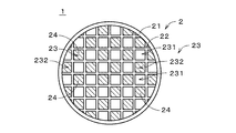
- FIG. 1 is a simplified plan view of the porous composite 1 according to the embodiment of the present invention.
- the porous composite 1 is a tubular member that is long in one direction, and FIG. 1 shows one end face of the porous composite 1 in the longitudinal direction.
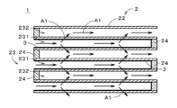
- FIG. 2 is a cross-sectional view showing the porous composite 1.
- FIG. 2 shows a part of a cross section along the longitudinal direction.
- the porous composite 1 is used, for example, as a gasoline particulate filter (GPF: Gasoline Particulate Filter) that collects particulate matter such as soot in exhaust gas discharged from a gasoline engine of an automobile or the like.
- GPF Gasoline Particulate Filter
- the porous composite 1 includes a porous base material 2 and a porous collecting layer 3.
- the base material 2 is a member having a honeycomb structure.
- the base material 2 includes a tubular outer wall 21 and a partition wall 22.
- the tubular outer wall 21 is a tubular portion extending in the longitudinal direction (that is, the left-right direction in FIG. 2).
- the cross-sectional shape of the tubular outer wall 21 perpendicular to the longitudinal direction is, for example, substantially circular.
- the cross-sectional shape may be another shape such as a polygon.
- the partition wall 22 is provided inside the tubular outer wall 21, and is a grid-like portion that partitions the inside into a plurality of cells 23.
- Each of the plurality of cells 23 is a space extending in the longitudinal direction.
- the cross-sectional shape of each cell 23 perpendicular to the longitudinal direction is, for example, a substantially square shape.
- the cross-sectional shape may be another shape such as a polygon or a circle.
- the plurality of cells 23 have the same cross-sectional shape in principle.
- the plurality of cells 23 may include cells 23 having different cross-sectional shapes.
- the base material 2 is a cell structure whose inside is partitioned into a plurality of cells 23 by a partition wall 22.
- the tubular outer wall 21 and the partition wall 22 are each a porous portion.
- the tubular outer wall 21 and the partition wall 22 are formed of, for example, ceramic.
- the main material of the cylindrical outer wall 21 and the partition 22 are preferably cordierite (2MgO ⁇ 2Al 2 O 3 ⁇ 5SiO 2).
- the material of the tubular outer wall 21 and the partition wall 22 may be a ceramic other than the cordierite, or may be a material other than the ceramic.
- the length of the tubular outer wall 21 in the longitudinal direction is, for example, 50 mm to 300 mm.
- the outer diameter of the tubular outer wall 21 is, for example, 50 mm to 300 mm.
- the thickness of the tubular outer wall 21 is, for example, 30 ⁇ m (micrometer) or more, preferably 50 ⁇ m or more.
- the thickness of the tubular outer wall 21 is, for example, 1000 ⁇ m or less, preferably 500 ⁇ m or less, and more preferably 350 ⁇ m or less.
- the length of the partition wall 22 in the longitudinal direction is substantially the same as that of the tubular outer wall 21.
- the thickness of the partition wall 22 is, for example, 30 ⁇ m or more, preferably 50 ⁇ m or more.
- the thickness of the partition wall 22 is, for example, 1000 ⁇ m or less, preferably 500 ⁇ m or less, and more preferably 350 ⁇ m or less.
- the porosity of the partition wall 22 is, for example, 20% or more, preferably 30% or more.
- the porosity of the partition wall 22 is, for example, 80% or less, preferably 70% or less.
- the porosity can be measured by, for example, the Archimedes method using pure water as a medium.
- the average pore diameter of the partition wall 22 is, for example, 5 ⁇ m or more, preferably 8 ⁇ m or more.
- the average pore diameter of the partition wall 22 is, for example, 30 ⁇ m or less, preferably 25 ⁇ m or less.
- the average pore diameter is measured by, for example, a mercury press-fitting method (JIS R1655 compliant).
- the cell density of the substrate 2 (that is, the number of cells 23 per unit area in a cross section perpendicular to the longitudinal direction) is, for example, 10 cells / cm 2 (square centimeters) or more, preferably 20 cells / cm 2 or more. , More preferably 30 cells / cm 2 or more.
- the cell density is, for example, 200 cells / cm 2 or less, preferably 150 cells / cm 2 or less.
- the size of the cell 23 is larger than the actual size, and the number of the cells 23 is smaller than the actual size.
- the size and number of cells 23 may be changed in various ways.
- the inside of the porous complex 1 has one end side (that is, the left side in FIG. 2) of the porous complex 1 in the longitudinal direction as an inlet and the other end side as an outlet. Gas such as exhaust gas flows through. Further, among the plurality of cells 23 of the porous composite 1, some of the plurality of cells 23 are provided with the sealing portion 24 at the end on the inlet side, and the remaining plurality of cells 23 are on the outlet side. A mesh sealing portion 24 is provided at the end portion.
- FIG. 1 depicts the inlet side of the porous composite 1. Further, in FIG. 1, in order to facilitate understanding of the figure, parallel diagonal lines are provided on the eye sealing portion 24 on the inlet side.
- the cell 23 having the eye-sealing portion 24 on the inlet side and the cell 23 not having the eye-sealing portion 24 on the inlet side are provided.
- the provided cells 23) are alternately arranged in the vertical direction and the horizontal direction in FIG.
- first cell 231 the cell 23 provided with the eye sealing portion 24 on the outlet side
- second cell 232 the cell 23 provided with the eye sealing portion 24 on the inlet side
- cell 23 the cell 23 provided with the eye sealing portion 24 on the inlet side
- the collection layer 3 is formed in a film shape on the surface of the base material 2.
- the collection layer 3 is provided in a plurality of first cells 231 provided with a sealing portion 24 on the outlet side, and the inner surface surface (that is, partition wall) of the plurality of first cells 231 is provided. 22 surface) is coated.
- the collection layer 3 is shown by a thick line.
- the collection layer 3 also covers the inner surface of the sealing portion 24 on the outlet side in the plurality of first cells 231.
- the collecting layer 3 does not exist in the plurality of second cells 232 provided with the sealing portion 24 on the inlet side. In other words, the inner surface of the plurality of second cells 232 is not covered by the collection layer 3 and is exposed.
- the collection layer 3 in the plurality of first cells 231 is formed of, for example, ceramic.
- the collection layer 3 contains at least one of silicon carbide, cordierite, mullite, aluminum oxide, silicon oxide, titanium oxide, zirconium oxide, iron oxide, and cerium oxide as a main material.
- the collection layer 3 may be formed of a material other than ceramic, or may be formed of a material other than ceramic.
- the average pore diameter of the collection layer 3 is preferably 0.1 ⁇ m or more and 20 ⁇ m or less.
- the average pore diameter is more preferably 4.1 ⁇ m or more and 20 ⁇ m or less, and further preferably 4.1 ⁇ m or more and 6 ⁇ m or less.
- the porosity of the collection layer 3 is preferably 50% or more and 90% or less.
- the porosity is more preferably 70% or more and 78% or less.
- the average particle size of the aggregate constituting the collection layer 3 is preferably 0.1 ⁇ m or more and 5 ⁇ m or less.
- the average particle size is more preferably 0.4 ⁇ m or more and 5 ⁇ m or less.
- the average pore size, porosity, and average particle size of the aggregate of the collection layer 3 are determined by the following methods.
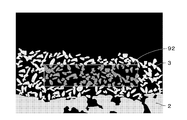
- the porous composite 1 is processed with a cross section polisher (CP) to expose a polished cross section including the collecting layer 3 and the base material 2, and the polished cross section is subjected to a predetermined magnification by an SEM (scanning electron microscope).
- An SEM image is acquired by taking a picture at (for example, 1000 times).
- FIG. 3 is a schematic diagram corresponding to the SEM image.
- the SEM image was image-analyzed using the image analysis software "Image-Pro ver. 9.3.2" manufactured by Nippon Roper Co., Ltd. to obtain the average pore diameter, pore ratio and aggregate of the collection layer 3. The average particle size of is obtained.
- a plurality of straight lines 91 extending parallel to the surface of the base material 2 are formed into the plurality of straight lines 91. Arrange in the vertical direction.
- One pixel of the SEM image corresponds to 0.1 ⁇ m ⁇ 0.1 ⁇ m.
- the width of each straight line 91 corresponds to one pixel of the SEM image, and is 0.1 ⁇ m in the example shown in FIG.
- the area of each region hereinafter, referred to as "bright region" to which the bright portion (that is, the aggregate of the collection layer 3) is connected on the straight line 91 is calculated.
- the area of each region (hereinafter, referred to as "dark region") in which the dark portion (that is, the pores of the collection layer 3) is connected on the straight line 91 is calculated.
- a region having a width of 0.2 ⁇ m (that is, a region having a width of two pixels) is extracted by the straight line 91.
- a straight line 91 having a width of 0.1 ⁇ m is arranged on the boundary line of two adjacent rows of pixels in the width direction (that is, rows of a plurality of pixels arranged in a direction perpendicular to the width direction). All pixels that overlap with the straight line 91 are subject to the area calculation.
- the areas of the bright region and the dark region are calculated in units of 0.01 ⁇ m 2 , and the region of less than 0.05 ⁇ m 2 (that is, the region of less than 5 pixels) is ignored as noise. Then, the arithmetic mean of the area of the dark region is obtained as the pore area extracted by the straight line 91.
- the pore area is the sum of the pore diameter and the pore width defined by the straight line 91 (that is, 0.2 ⁇ m corresponding to two pixels). Therefore, the average pore diameter of the collection layer 3 is calculated by dividing the arithmetic mean of the area of the dark region described above by 0.2 ⁇ m (that is, the pore width). Further, the porosity of the collection layer 3 is calculated by dividing the total area of the dark region by the sum of the total area of the bright region and the total area of the dark region.
- each bright portion that is, each aggregate particle
- the ferret diameter JIS Z 8827-1
- the distance between the two straight lines is defined as the ferret diameter.
- the arithmetic mean of the ferret diameters of all the aggregate particles is obtained as the average particle size of the aggregate particles.
- the arithmetic mean height Sa (hereinafter, also referred to as “total Sa”) indicating the surface roughness of the surface is preferably 0.1 ⁇ m or more and 12 ⁇ m or less.
- the total Sa is more preferably 0.1 ⁇ m or more and 10 ⁇ m or less.
- the arithmetic mean height Sa (hereinafter, also referred to as “outlet side Sa”) at the end on the outlet side where the gas flows out is 0.1 ⁇ m or more and 15 ⁇ m or less.
- the outlet side Sa is more preferably 0.1 ⁇ m or more and 10 ⁇ m or less.
- the overall average film thickness of the collection layer 3 (hereinafter, also referred to as “overall average film thickness”) is preferably 10 ⁇ m or more and 40 ⁇ m or less.
- the overall average film thickness is more preferably 30 ⁇ m or more and 40 ⁇ m or less.
- the average film thickness of the collection layer 3 at the end on the outlet side (hereinafter, also referred to as “outlet side average film thickness”) is 20 ⁇ m or more and 50 ⁇ m or less.
- the outlet-side average film thickness is more preferably 35 ⁇ m or more and 50 ⁇ m or less.
- the outlet-side average film thickness is larger than the overall average film thickness.
- the arithmetic average height Sa of the surface of the collection layer 3 and the average film thickness of the collection layer 3 are measured by a 3D shape measuring machine. Specifically, first, by cutting the porous composite 1 in two cross sections parallel to the longitudinal direction, a substantially flat portion sandwiched between the two cross sections is obtained as a sample. The two cross sections face each other with a central axis extending in the longitudinal direction of the porous composite 1 in between, and at least one cross section includes a plurality of cells 23.
- the length in the longitudinal direction of the sample is the same as the length in the longitudinal direction of the porous composite 1, and the width in the width direction of the sample is the diameter of the porous composite 1 (that is, the outer diameter of the tubular outer wall 21). ) Is the same.
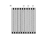
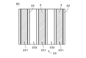
- FIG. 6 is a diagram showing one main surface of the acquired sample 80 (that is, a vertical cross section of the porous composite 1).
- a plurality of cells 23 extending in the vertical direction in the drawing are arranged in the horizontal direction in the drawing.
- the vertical direction and the horizontal direction in the figure correspond to the longitudinal direction of the porous composite 1 and the radial direction (that is, the width direction) about the central axis, respectively.
- the lower side in the figure corresponds to the above-mentioned inlet side, and the upper side in the figure corresponds to the above-mentioned exit side.
- the cell 23 with parallel diagonal lines is the cell 23 provided with the collection layer 3.
- each of the measurement regions 811 to 813, 821 to 823, and 831 to 833 are substantially rectangular regions having a pair of sides parallel to each other in the longitudinal direction and the width direction of the sample 80.
- the measurement areas 821 to 823 are arranged in the vertical direction in order from the lower side (that is, the entrance side) in the center of the measurement image in the width direction.
- the measurement areas 811 to 813 are arranged in the vertical direction in order from the lower side on the right side of the measurement areas 821 to 823.
- the measurement areas 831 to 833 are arranged in the vertical direction in order from the lower side on the left side of the measurement areas 821 to 823.
- the width of each of the measurement regions 811 to 813, 821 to 823, and 831 to 833 in the width direction is approximately 1/3 of the width of the sample 80.
- the length of each of the measurement regions 811 to 813, 821 to 823, and 831 to 833 in the longitudinal direction is substantially equal to 20% of the total length of the sample 80 in the longitudinal direction (hereinafter, simply referred to as “total length”).
- the measurement areas 811, 821, and 831 are located at substantially the same position in the longitudinal direction.
- the centers of the measurement regions 811, 821, and 831 in the longitudinal direction are located above the lower end of the sample 80 and at a distance substantially equal to 20% of the total length of the sample 80.
- the measurement areas 812, 822, and 832 are located at substantially the same positions in the longitudinal direction.
- the longitudinal center of the measurement regions 812, 822, and 832 is located substantially in the longitudinal center of the sample 80.
- the measurement areas 813, 823, and 833 are located at substantially the same positions in the longitudinal direction.
- the longitudinal centers of the measurement regions 813, 823, and 833 are located below the upper end of the sample 80 at a distance approximately equal to 20% of the total length of the sample 80.
- FIG. 8 is a diagram schematically showing an image obtained by a 3D shape measuring machine.
- the three first cells 231 and the two second cells 232 are arranged alternately in the width direction.
- parallel diagonal lines are provided on the collection layer 3 of each first cell 231 for easy understanding of the figure.
- the cross section of the collection layer 3 on the partition wall 22 is shown by a thick line.
- the arithmetic mean height Sa of the surface of the collection layer 3 in one first cell 231 in the image is calculated based on the image shown in FIG. Specifically, the arithmetic mean height Sa of the strip-shaped region extending in the longitudinal direction in the central portion in the width direction of the first cell 231 is calculated.
- the calculated arithmetic mean height Sa is acquired as Sa of the collection layer 3 in the measurement region 821.
- the Sa of the collection layer 3 calculated for each first cell 231 in the image shown in FIG. 8 was substantially the same. Further, the Sa of the collection layer 3 measured by changing the imaging point by the 3D shape measuring machine in the measurement area 821 was substantially the same. The same was true for the other measurement regions 811 to 813, 822 to 823, and 831 to 833.
- the Sa of the collection layer 3 in the measurement area 821 is measured, the Sa of the collection layer 3 in the measurement areas 822 to 823 is measured by the same method. Further, Sa of the collection layer 3 in the measurement areas 811 to 813 is also measured by the same method. Then, the arithmetic mean of Sa of the collection layer 3 in the six measurement areas (that is, the measurement areas 811 to 813 and 821 to 823) is obtained, and the arithmetic mean is acquired as the above-mentioned total Sa. Further, the arithmetic mean of Sa of the collection layer 3 in the two measurement regions on the outlet side (that is, measurement regions 813 and 823) is acquired as the above-mentioned outlet side Sa. In the calculation of the entire Sa and the outlet side Sa, the Sa of the collection layer 3 in the measurement areas 831 to 833 may be used instead of the Sa of the collection layer 3 in the measurement areas 811 to 813.
- the thickness direction of the surface of the collecting layer 3 in the first cell 231 at the center in the width direction in the image that is, the direction perpendicular to the paper surface in the drawing).
- the average position in the thickness direction of the surface of the partition wall 22 in the two second cells 232 adjacent to both sides of the first cell 231 are calculated.
- the average position of the surface of the partition wall 22 in the extending strip-shaped region is calculated.
- the average film thickness of the collection layer 3 in the first cell 231 is calculated by subtracting the arithmetic mean of the average positions in the two second cells 232 from the average position in the first cell 231.
- the calculated average film thickness is acquired as the average film thickness of the collection layer 3 in the measurement region 821.
- the average film thickness of the collection layer 3 calculated for each first cell 231 in the image shown in FIG. 8 was substantially the same. Further, the average film thickness of the collection layer 3 measured by changing the imaging point by the 3D shape measuring machine in the measurement area 821 was also substantially the same. The same was true for the other measurement regions 811 to 813, 822 to 823, and 831 to 833.
- the average film thickness of the collection layer 3 in the measurement area 821 is measured, the average film thickness of the collection layer 3 in the measurement areas 822 to 823 is measured by the same method. Further, the average film thickness of the collection layer 3 in the measurement regions 811 to 813 is also measured by the same method. Then, the arithmetic average of the average film thickness of the collection layer 3 in the six measurement regions (that is, the measurement regions 811 to 813 and 821 to 823) is obtained, and the arithmetic mean is acquired as the above-mentioned overall average film thickness. To.
- the arithmetic mean of the average film thickness of the collection layer 3 in the two measurement regions on the outlet side is acquired as the above-mentioned average film thickness on the outlet side.
- the average film thickness of the collection layer 3 in the measurement areas 831 to 833 is used instead of the average film thickness of the collection layer 3 in the measurement areas 811 to 813. May be done.
- the gas flowing into the porous composite 1 is in the first cell 231 whose inlet side is not sealed. It flows into the first cell 231 from the entrance, passes through the collection layer 3 and the partition wall 22 from the first cell 231 and moves to the second cell 232 whose outlet side is not sealed. At this time, the particulate matter in the gas is efficiently collected in the collection layer 3.
- the porous composite 1 When the porous composite 1 is manufactured, first, the outer surface of the tubular outer wall 21 of the base material 2 is covered with a liquid-impermeable sheet member. For example, an impermeable film is wrapped over substantially the entire outer surface of the tubular outer wall 21.
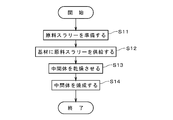
- a raw material slurry for forming the collection layer 3 is prepared (step S11).
- the raw material slurry is prepared by adding particles that are the raw material of the collection layer 3 (hereinafter, referred to as “collection layer particles”), pore-forming agent particles, a flocculant, and the like to water and mixing them. ..
- the capture layer particles are, for example, silicon carbide (SiC) or cerium oxide (CeO 2 ) particles.
- the raw material slurry includes particles in which collecting layer particles, pore-forming agent particles and the like are aggregated (hereinafter, referred to as “aggregated particles”).
- the type and amount of the aggregating agent are determined so that the particle size of the agglomerated particles is larger than the average pore size of the base material 2. This prevents or suppresses the infiltration of aggregated particles into the pores of the base material 2 in step S12, which will be described later.
- the viscosity of the raw material slurry is, for example, 2 mPa ⁇ s to 30 mPa ⁇ s.
- the inlets that is, the eye seals of the plurality of first cells 231 with respect to the plurality of first cells 231 where the collection layer 3 is to be formed.
- the raw material slurry is supplied from the end portion on which 24 is not provided (step S12).
- the water in the raw material slurry permeates through the partition wall 22 of the base material 2 and moves to the adjacent second cell 232, and from the end of the second cell 232 where the sealing portion 24 is not provided, the base It flows out to the outside of the material 2.
- the agglomerated particles in the raw material slurry adhere to the inner surface of the first cell 231 to which the raw material slurry is supplied without passing through the partition wall 22. As a result, an intermediate in which aggregated particles are substantially evenly adhered to the inner surface of the first cell 231 of the base material 2 is formed.
- the intermediate from which the water has flowed out is dried (step S13).
- the intermediate is further dried by drying at room temperature for 12 hours and then heating at 80 ° C. for 12 hours.
- the collection layer particles in the large number of aggregated particles adhering to the base material 2 are bonded and spread on the surface of the base material 2 to form the porous collection layer 3.
- the pore-forming agent particles contained in the collection layer 3 are burnt and removed to form pores in the collection layer 3.
- the firing temperature and firing time in step S14 are, for example, 1200 ° C. and 2 hours, respectively.
- the arithmetic mean height Sa of the surface of the collection layer 3 formed in step S14 is, for example, from the start of supply of the raw material slurry in step S12 to the end of formation of the intermediate (that is, the end of water outflow from the base material 2). It can be adjusted by changing the time required until.
- the completion of the formation of the intermediate is, for example, the time when the weight of the base material 2 to which the raw material slurry is supplied is continuously measured and the measured weight is reduced to a predetermined weight.
- the method for producing the porous composite 1 for example, by shortening the time required from the start of supply of the raw material slurry to the end of formation of the intermediate in step S12, the above-mentioned arithmetic mean height Sa becomes smaller.
- the reduction in the required time is realized, for example, by sucking the base material 2 with an intake device or the like in step S12 to promote the outflow of water in the raw material slurry to the outside of the base material 2. ..
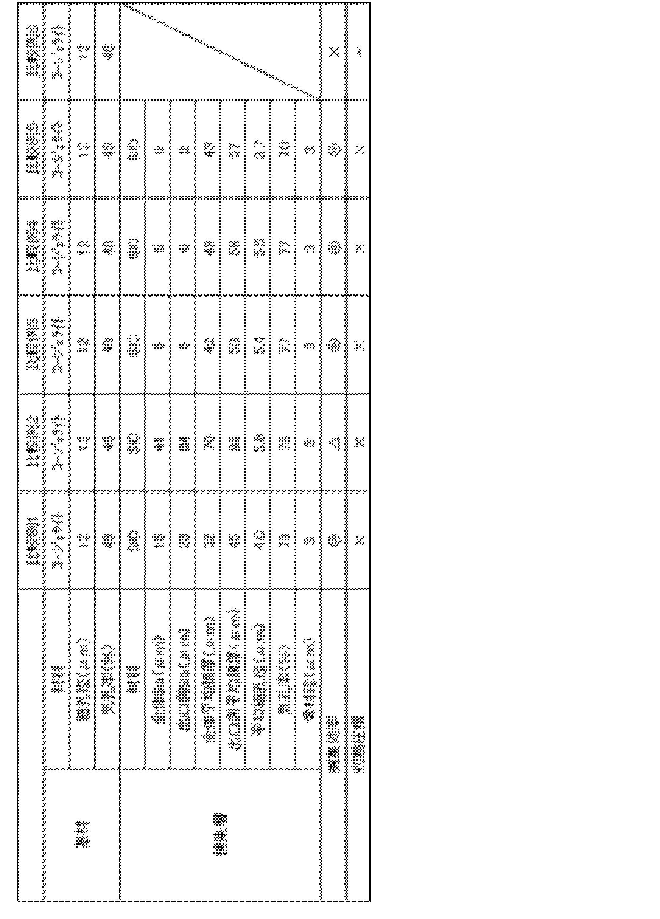
- the main material of substrate 2 is cordierite, with average pore size and porosity of 12 ⁇ m and 48%, respectively.
- the main material of the collection layer 3 is SiC
- the main material of the collection layer 3 is CeO 2 .
- the total Sa of the collection layer 3 is 4 ⁇ m to 11 ⁇ m, and the outlet side Sa is 5 ⁇ m to 14 ⁇ m.
- the overall average film thickness of the collection layer 3 is 27 ⁇ m to 39 ⁇ m, and the average film thickness on the outlet side is 33 ⁇ m to 47 ⁇ m.
- the average pore size of the collection layer 3 is 3.2 ⁇ m to 6.1 ⁇ m, and the porosity is 67% to 79%.
- the average particle size of the aggregates constituting the collection layer 3 is 2 ⁇ m to 3 ⁇ m.
- Comparative Examples 1 to 6 the main material of the base material 2 is cordierite, and the average pore diameter and porosity are 12 ⁇ m and 48%, respectively, as in Examples 1 to 7.
- the main material of the collection layer 3 is SiC, and in Comparative Example 6, the collection layer 3 is not provided. That is, the porous composite 1 of Comparative Example 6 is composed of only the base material 2 made of Cordellite.
- the total Sa of the collection layer 3 is 5 ⁇ m to 41 ⁇ m, and the outlet side Sa is 6 ⁇ m to 84 ⁇ m.
- the overall average film thickness of the collection layer 3 is 32 ⁇ m to 70 ⁇ m, and the average film thickness on the outlet side is 45 ⁇ m to 98 ⁇ m.
- the average pore size of the collection layer 3 is 3.7 ⁇ m to 5.8 ⁇ m, and the porosity is 70% to 78%.
- the average particle size of the aggregates constituting the collection layer 3 is 3 ⁇ m.
- the total Sa of the collection layer 3 is larger than 12 ⁇ m, and the outlet side Sa is also larger than 15 ⁇ m.
- the overall average film thickness of the collection layer 3 is larger than 40 ⁇ m, and the average film thickness on the outlet side is also larger than 50 ⁇ m.
- Example 1 to 7 and Comparative Examples 1 to 6 the quality of the collection efficiency of the particulate matter by the porous composite 1 and the quality of the suppression of the initial pressure drop (that is, the magnitude of the increase rate of the initial pressure drop) are determined. did.
- the collection efficiency was determined as follows. First, each of the porous composites 1 of each example and each comparative example was mounted as a GPF in the exhaust system of a passenger vehicle having a direct-injection gasoline engine with a displacement of 2 liters, and a vehicle test was conducted using a chassis dynamometer.
- the number of particulate matter emitted in the exhaust gas when operated in the European regulated operation mode was measured by a measurement method in accordance with PMP (European regulated particulate measurement protocol). Further, the same vehicle test was conducted without mounting the GPF in the exhaust system, and the number of particulate matter discharged in the exhaust gas was measured by the same measurement method. The difference between the measured number of particulate matter discharged and the standard number of discharged particles for each Example and each comparative example is determined by the standard number of discharged particles, with the number of particulate matter discharged without GPF as the "standard number of discharged particles". The divided value (%) was defined as "collection efficiency (%)".
- the rate of increase in initial pressure drop was calculated as follows. First, room temperature air is supplied to the porous composite 1 of each example and each comparative example at a flow rate of 10 Nm 3 / min, and the pressure difference before and after the porous composite 1 (that is, the inflow side and the outflow of air). The differential pressure on the side) was measured respectively. Then, the rate of increase in the pressure difference of each Example and each Comparative Example with respect to the pressure difference of Comparative Example 6 (only the base material 2) was determined as the “rate of increase in initial pressure loss” of the porous composite 1. Specifically, the rate of increase in initial pressure loss (%) is (AB) / B ⁇ , where A is the pressure difference between each Example and each Comparative Example and B is the pressure difference in Comparative Example 6. Obtained at 100.
- the quality of collection efficiency is indicated by symbols. Specifically, the case where the collection efficiency is 92.5% or more is indicated by “ ⁇ ”, and the case where the collection efficiency is 90% or more and less than 92.5% is indicated by “ ⁇ ”. Further, the case where the collection efficiency is 87.5% or more and less than 90% is indicated by “ ⁇ ”, and the case where the collection efficiency is less than 87.5% is indicated by “x”.
- the quality of initial pressure loss suppression is also indicated by symbols. Specifically, the case where the increase rate of the initial pressure drop is less than 10% is indicated by " ⁇ ", and the case where the increase rate of the initial pressure loss is 10% or more and less than 13% is indicated by " ⁇ ". The case where the rate of increase is 13% or more is indicated by "x”.
- Example 1 the collection efficiency was 92.5% or more, and the rate of increase in initial pressure drop was less than 10%, both of which were good.
- Example 2 the collection efficiency was as good as 92.5% or more, and the rate of increase in initial pressure drop was 10% or more and less than 13%, which was within the permissible range. It is considered that the reason why the increase rate of the initial pressure drop in Example 2 was slightly large was that the total Sa and the outlet side Sa of the collection layer 3 were larger than 10 ⁇ m.
- Example 3 the collection efficiency was 90% or more and less than 92.5%, and the initial pressure drop was less than 10%, both of which were good. It is considered that the reason why the repair efficiency was slightly reduced in Example 3 is that the average film thickness on the outlet side of the collection layer 3 is less than 35 ⁇ m.
- Example 4 the collection efficiency was as good as 92.5% or more, and the rate of increase in initial pressure drop was 10% or more and less than 13%, which was within the permissible range. It is considered that the reason why the increase rate of the initial pressure drop in Example 2 was slightly large was that the average pore diameter of the collection layer 3 was less than 4.1 ⁇ m. In Example 5, the collection efficiency was 87.5% or more and less than 90%, which was within the permissible range, and the rate of increase in initial pressure drop was good, less than 10%. It is considered that the reason why the collection efficiency was slightly reduced in Example 5 was that the average pore diameter of the collection layer 3 was larger than 6 ⁇ m and the porosity was larger than 78%.
- Example 6 the collection efficiency was 92.5% or more, and the rate of increase in initial pressure drop was less than 10%, both of which were good.
- Example 7 the collection efficiency was as good as 92.5% or more, and the rate of increase in initial pressure drop was 10% or more and less than 13%, which was within the permissible range. It is considered that the reason why the rate of increase in the initial pressure drop in Example 7 was slightly large was that the average pore diameter of the collection layer 3 was less than 4.1 ⁇ m.
- Comparative Examples 1 to 5 the rate of increase in initial pressure drop was as large as 13% or more. It is considered that the reason why the increase rate of the initial pressure drop is excessive in Comparative Example 1 is that the total Sa is larger than 12 ⁇ m and the outlet side Sa is larger than 15 ⁇ m. In Comparative Example 2, the increase rate of the initial pressure drop is excessive because the overall Sa is larger than 12 ⁇ m, the outlet side Sa is larger than 15 ⁇ m, the overall average film thickness is larger than 40 ⁇ m, and the outlet side average film thickness. Is considered to be the cause of being larger than 50 ⁇ m.
- Comparative Examples 3 to 5 it is considered that the reason why the increase rate of the initial pressure drop is excessive in Comparative Examples 3 to 5 is that the overall average film thickness is larger than 40 ⁇ m and the outlet side average film thickness is larger than 50 ⁇ m. In Comparative Example 6, since the collection layer 3 was not provided, the collection efficiency was very small, less than 87.5%.
- the porous composite 1 includes a porous base material 2 and a porous collecting layer 3 formed on the base material 2.
- the base material 2 has a honeycomb structure in which the inside is partitioned into a plurality of cells 23 extending in the longitudinal direction by a partition wall 22.
- a plurality of first cells 231 that are once sealed in the longitudinal direction and a plurality of second cells 232 that are sealed at the other end in the longitudinal direction are alternately arranged.
- the collection layer 3 covers the inner surfaces of the plurality of first cells 231.
- the total Sa which is the arithmetic mean height Sa indicating the surface roughness of the surface of the collection layer 3 in the plurality of first cells 231 is 0.1 ⁇ m or more and 12 ⁇ m or less.
- the frictional resistance between the gas flowing in the first cell 231 and the collection layer 3 can be reduced.
- the pressure loss in the porous composite 1 can be reduced.
- the unevenness of the surface of the collection layer 3 in the circumferential direction is reduced.
- the uniformity of the collection of the particulate matter in the circumferential direction can be improved at each of the positions, so that the collection efficiency of the particulate matter in the porous composite 1 can be improved.
- the surface of the collecting layer 3 becomes smooth, it is possible to prevent the surface layer portion of the collecting layer 3 from being chipped or cracked. As a result, the durability of the porous composite 1 can be improved.
- the overall average film thickness which is the average film thickness of the collection layer 3 in the plurality of first cells 231 is 10 ⁇ m or more and 40 ⁇ m or less.
- the outlet side Sa which is the arithmetic mean height Sa of the surface of the collection layer 3 at one end side (that is, the outlet side) of the plurality of first cells 231 in the longitudinal direction, is 0.1 ⁇ m or more. And it is preferably 15 ⁇ m or less.
- the pressure loss in the porous composite 1 can be further reduced and the collecting efficiency is further improved. You can also do it.
- the average film thickness on the outlet side which is the average film thickness of the collection layer 3 at the end portion (that is, the end portion on the outlet side) of the plurality of first cells 231 is 35 ⁇ m or more and 50 ⁇ m or less. Is preferable. As a result, the pressure loss in the porous composite 1 can be further reduced, and the collection efficiency can be further improved.
- the average pore diameter of the collection layer 3 in the plurality of first cells 231 is preferably 0.1 ⁇ m or more and 20 ⁇ m or less. As a result, it is possible to suppress an increase in pressure loss due to a decrease in the average pore diameter, and it is also possible to suppress a decrease in collection efficiency due to an increase in the average pore diameter. In other words, the pressure loss in the porous composite 1 can be further reduced, and the collection efficiency can be further improved.
- the porosity of the collection layer 3 in the plurality of first cells 231 is preferably 50% or more and 90% or less. As a result, it is possible to efficiently suppress the increase in pressure loss in the porous composite 1.
- the average particle size of the aggregate of the collection layer 3 in the plurality of first cells 231 is preferably 0.1 ⁇ m or more and 5 ⁇ m or less. As a result, the pressure loss in the porous composite 1 can be further reduced, and the collection efficiency can be further improved.
- the collection layer 3 in the plurality of first cells 231 contains at least one of silicon carbide, cordierite, mullite, aluminum oxide, silicon oxide, titanium oxide, zirconium oxide, iron oxide, and cerium oxide. Is preferable. As described above, by forming the collecting layer 3 using the ceramic material having relatively high heat resistance, the production of the porous composite 1 including the firing step can be preferably performed.
- the collection layer 3 does not exist in the plurality of second cells 232. This makes it possible to prevent an unnecessary increase in pressure loss in the porous composite 1.
- the main material of the base material 2 is cordierite. Further, preferably, the average pore diameter of the partition wall 22 is 5 ⁇ m or more and 30 ⁇ m or less, and the porosity of the partition wall 22 is 30% or more and 70% or less. As a result, it is possible to preferably realize reduction of pressure loss and improvement of collection efficiency in the porous composite 1.
- the porous composite 1 As described above, according to the porous composite 1, the pressure loss can be reduced and the collection efficiency can be improved. Therefore, the porous composite 1 is particularly suitable for GPF that collects particulate matter in the exhaust gas discharged from the gasoline engine.
- the above-mentioned porous composite 1 can be changed in various ways.
- the structure of the porous composite 1 may be changed in various ways.
- the collection layer 3 may be provided on the inner surface of all the cells 23.
- porous complex 1 is not limited to the above-mentioned GPF, and the porous complex 1 may be used as another filter such as a diesel particulate filter (DPF). Alternatively, the porous composite 1 may be used for applications other than filters.
- DPF diesel particulate filter
- the method for producing the porous composite 1 is not limited to that illustrated in FIG. 9, and may be changed in various ways.
- the method of supplying the raw material slurry to the base material 2 may be changed in various ways.
- the supply of the raw material of the collection layer 3 to the base material 2 is not limited to the filtration method using the raw material slurry, and may be performed by various methods such as a dip method, a spray method or a dry method.
- the drying method and drying time of the intermediate in step S13, the firing temperature and firing time of the intermediate in step S14, and the like may be variously changed.
- the present invention can be used for a filter that collects particulate matter, for example, a gasoline particulate filter that collects particulate matter in exhaust gas discharged from a gasoline engine.
Landscapes
- Chemical & Material Sciences (AREA)
- Geometry (AREA)
- Physics & Mathematics (AREA)
- Engineering & Computer Science (AREA)
- Chemical Kinetics & Catalysis (AREA)
- Ceramic Engineering (AREA)
- Organic Chemistry (AREA)
- Materials Engineering (AREA)
- Structural Engineering (AREA)
- Geology (AREA)
- Life Sciences & Earth Sciences (AREA)
- Inorganic Chemistry (AREA)
- Combustion & Propulsion (AREA)
- Mechanical Engineering (AREA)
- General Engineering & Computer Science (AREA)
- Nanotechnology (AREA)
- Filtering Materials (AREA)
- Filtering Of Dispersed Particles In Gases (AREA)
- Porous Artificial Stone Or Porous Ceramic Products (AREA)
- Processes For Solid Components From Exhaust (AREA)
Abstract
Description

2 基材
3 捕集層
22 隔壁
23 セル
231 第1セル
232 第2セル
S11~S14 ステップ
Claims (10)
- 多孔質複合体であって、
多孔質の基材と、
前記基材上に形成された多孔質の捕集層と、
を備え、
前記基材は、内部が隔壁により長手方向に延びる複数のセルに仕切られたハニカム構造を有し、
前記複数のセルでは、長手方向の一端が封止された複数の第1セルと、長手方向の他端が封止された複数の第2セルとが交互に配列されており、
前記捕集層は、前記複数の第1セルの内側面を被覆し、
前記複数の第1セルにおける前記捕集層の表面の面粗さを示す算術平均高さSaである全体Saは、0.1μm以上かつ12μm以下であり、
前記複数の第1セルにおける前記捕集層の平均膜厚である全体平均膜厚は、10μm以上かつ40μm以下である。 - 請求項1記載の多孔質複合体であって、
前記複数の第1セルの長手方向の前記一端側の端部における前記捕集層の表面の算術平均高さSaである出口側Saは、0.1μm以上かつ15μm以下である。 - 請求項2に記載の多孔質複合体であって、
前記複数の第1セルの前記端部における前記捕集層の平均膜厚である出口側平均膜厚は、35μm以上かつ50μm以下である。 - 請求項1ないし3のいずれか1つに記載の多孔質複合体であって、
前記複数の第1セルにおける前記捕集層の平均細孔径は、0.1μm以上かつ20μm以下である。 - 請求項1ないし4のいずれか1つに記載の多孔質複合体であって、
前記複数の第1セルにおける前記捕集層の気孔率は、50%以上かつ90%以下である。 - 請求項1ないし5のいずれか1つに記載の多孔質複合体であって、
前記複数の第1セルにおける前記捕集層の骨材の平均粒径は、0.1μm以上かつ5μm以下である。 - 請求項1ないし6のいずれか1つに記載の多孔質複合体であって、
前記複数の第1セルにおける前記捕集層は、炭化ケイ素、コージェライト、ムライト、酸化アルミニウム、酸化ケイ素、酸化チタン、酸化ジルコニウム、酸化鉄、酸化セリウムのうち少なくとも1つを含む。 - 請求項1ないし7のいずれか1つに記載の多孔質複合体であって、
前記捕集層は、前記複数の第2セル内には存在しない。 - 請求項1ないし8のいずれか1つに記載の多孔質複合体であって、
前記隔壁の主材料はコージェライトであり、
前記隔壁の平均細孔径は、5μm以上かつ30μm以下であり、
前記隔壁の気孔率は、30%以上かつ70%以下である。 - 請求項1ないし9のいずれか1つに記載の多孔質複合体であって、
ガソリンエンジンから排出される排ガス中の粒子状物質を捕集するガソリン・パティキュレート・フィルタである。
Priority Applications (5)
| Application Number | Priority Date | Filing Date | Title |
|---|---|---|---|
| JP2021508613A JP7198911B2 (ja) | 2019-03-28 | 2019-03-28 | 多孔質複合体 |
| PCT/JP2019/013670 WO2020194681A1 (ja) | 2019-03-28 | 2019-03-28 | 多孔質複合体 |
| DE112019007100.9T DE112019007100B4 (de) | 2019-03-28 | 2019-03-28 | Poröser Verbundstoff |
| CN201980093094.2A CN113597334B (zh) | 2019-03-28 | 2019-03-28 | 多孔质复合体 |
| US17/445,340 US11883770B2 (en) | 2019-03-28 | 2021-08-18 | Porous composite |
Applications Claiming Priority (1)
| Application Number | Priority Date | Filing Date | Title |
|---|---|---|---|
| PCT/JP2019/013670 WO2020194681A1 (ja) | 2019-03-28 | 2019-03-28 | 多孔質複合体 |
Related Child Applications (1)
| Application Number | Title | Priority Date | Filing Date |
|---|---|---|---|
| US17/445,340 Continuation US11883770B2 (en) | 2019-03-28 | 2021-08-18 | Porous composite |
Publications (1)
| Publication Number | Publication Date |
|---|---|
| WO2020194681A1 true WO2020194681A1 (ja) | 2020-10-01 |
Family
ID=72611245
Family Applications (1)
| Application Number | Title | Priority Date | Filing Date |
|---|---|---|---|
| PCT/JP2019/013670 Ceased WO2020194681A1 (ja) | 2019-03-28 | 2019-03-28 | 多孔質複合体 |
Country Status (5)
| Country | Link |
|---|---|
| US (1) | US11883770B2 (ja) |
| JP (1) | JP7198911B2 (ja) |
| CN (1) | CN113597334B (ja) |
| DE (1) | DE112019007100B4 (ja) |
| WO (1) | WO2020194681A1 (ja) |
Cited By (1)
| Publication number | Priority date | Publication date | Assignee | Title |
|---|---|---|---|---|
| DE112022003380T5 (de) | 2021-08-03 | 2024-04-18 | Ngk Insulators, Ltd. | Poröser verbundwerkstoff |
Families Citing this family (5)
| Publication number | Priority date | Publication date | Assignee | Title |
|---|---|---|---|---|
| CN120618112A (zh) * | 2019-05-08 | 2025-09-12 | 康宁股份有限公司 | 蜂窝过滤体以及包含蜂窝过滤体的微粒过滤器 |
| JP6902153B1 (ja) | 2020-03-26 | 2021-07-14 | 日本碍子株式会社 | 柱状ハニカム構造フィルタ及びその製造方法 |
| KR102538298B1 (ko) * | 2020-12-29 | 2023-05-30 | 한국세라믹기술원 | 수송기관의 브레이크 장치에서 발생한 미세먼지를 포집하기 위한 포집장치 및 그 제조방법 |
| EP4406649A4 (en) * | 2021-09-22 | 2024-12-18 | Mitsui Mining & Smelting Co., Ltd. | Exhaust gas purification catalyst |
| JP7595208B1 (ja) * | 2024-03-29 | 2024-12-05 | 日本碍子株式会社 | ハニカム構造体 |
Citations (8)
| Publication number | Priority date | Publication date | Assignee | Title |
|---|---|---|---|---|
| JPH07163823A (ja) * | 1993-12-15 | 1995-06-27 | Ngk Insulators Ltd | 多孔質セラミックハニカムフィルタ |
| JPH08931A (ja) * | 1994-06-21 | 1996-01-09 | Ngk Insulators Ltd | 排ガスフィルタおよびそれを使用した排ガス処理装置 |
| WO2003080539A1 (fr) * | 2002-03-27 | 2003-10-02 | Ngk Insulators, Ltd. | Corps a structure en nid d'abeilles, son procede de fabrication, et procede de mesure de la distorsion peripherique externe de ce corps |
| WO2004076027A1 (ja) * | 2003-02-28 | 2004-09-10 | Ibiden Co., Ltd. | セラミックハニカム構造体 |
| WO2008047558A1 (fr) * | 2006-09-28 | 2008-04-24 | Hitachi Metals, Ltd. | structure céramique en nid d'abeille et son procédé de fabrication |
| WO2008093727A1 (ja) * | 2007-01-30 | 2008-08-07 | Kyocera Corporation | ハニカム構造体および浄化装置 |
| JP2013039513A (ja) * | 2011-08-12 | 2013-02-28 | Sumitomo Chemical Co Ltd | ハニカムフィルタ |
| JP2013527025A (ja) * | 2010-03-26 | 2013-06-27 | イメリス | セラミックハニカム構造体 |
Family Cites Families (7)
| Publication number | Priority date | Publication date | Assignee | Title |
|---|---|---|---|---|
| JP2007296512A (ja) * | 2006-04-05 | 2007-11-15 | Ngk Insulators Ltd | ハニカムフィルタ |
| JP5649945B2 (ja) | 2009-12-25 | 2015-01-07 | 日本碍子株式会社 | 表面捕集層付き担体及び触媒担持表面捕集層付き担体 |
| JP4920752B2 (ja) | 2010-01-05 | 2012-04-18 | 日本碍子株式会社 | ハニカム構造体 |
| JP5369029B2 (ja) * | 2010-03-12 | 2013-12-18 | 日本碍子株式会社 | ハニカムフィルタ |
| JP5498821B2 (ja) * | 2010-03-12 | 2014-05-21 | 日本碍子株式会社 | ハニカムフィルタ及びその製造方法 |
| WO2011125766A1 (ja) * | 2010-03-31 | 2011-10-13 | 日本碍子株式会社 | ハニカムフィルタ |
| WO2011149744A1 (en) | 2010-05-25 | 2011-12-01 | Corning Incorporated | Cordierite membrane on a cordierite monolith |
-
2019
- 2019-03-28 DE DE112019007100.9T patent/DE112019007100B4/de active Active
- 2019-03-28 CN CN201980093094.2A patent/CN113597334B/zh active Active
- 2019-03-28 WO PCT/JP2019/013670 patent/WO2020194681A1/ja not_active Ceased
- 2019-03-28 JP JP2021508613A patent/JP7198911B2/ja active Active
-
2021
- 2021-08-18 US US17/445,340 patent/US11883770B2/en active Active
Patent Citations (8)
| Publication number | Priority date | Publication date | Assignee | Title |
|---|---|---|---|---|
| JPH07163823A (ja) * | 1993-12-15 | 1995-06-27 | Ngk Insulators Ltd | 多孔質セラミックハニカムフィルタ |
| JPH08931A (ja) * | 1994-06-21 | 1996-01-09 | Ngk Insulators Ltd | 排ガスフィルタおよびそれを使用した排ガス処理装置 |
| WO2003080539A1 (fr) * | 2002-03-27 | 2003-10-02 | Ngk Insulators, Ltd. | Corps a structure en nid d'abeilles, son procede de fabrication, et procede de mesure de la distorsion peripherique externe de ce corps |
| WO2004076027A1 (ja) * | 2003-02-28 | 2004-09-10 | Ibiden Co., Ltd. | セラミックハニカム構造体 |
| WO2008047558A1 (fr) * | 2006-09-28 | 2008-04-24 | Hitachi Metals, Ltd. | structure céramique en nid d'abeille et son procédé de fabrication |
| WO2008093727A1 (ja) * | 2007-01-30 | 2008-08-07 | Kyocera Corporation | ハニカム構造体および浄化装置 |
| JP2013527025A (ja) * | 2010-03-26 | 2013-06-27 | イメリス | セラミックハニカム構造体 |
| JP2013039513A (ja) * | 2011-08-12 | 2013-02-28 | Sumitomo Chemical Co Ltd | ハニカムフィルタ |
Cited By (1)
| Publication number | Priority date | Publication date | Assignee | Title |
|---|---|---|---|---|
| DE112022003380T5 (de) | 2021-08-03 | 2024-04-18 | Ngk Insulators, Ltd. | Poröser verbundwerkstoff |
Also Published As
| Publication number | Publication date |
|---|---|
| DE112019007100B4 (de) | 2025-06-26 |
| US11883770B2 (en) | 2024-01-30 |
| US20210379523A1 (en) | 2021-12-09 |
| CN113597334A (zh) | 2021-11-02 |
| JP7198911B2 (ja) | 2023-01-04 |
| JPWO2020194681A1 (ja) | 2020-10-01 |
| DE112019007100T5 (de) | 2021-12-16 |
| CN113597334B (zh) | 2022-08-19 |
Similar Documents
| Publication | Publication Date | Title |
|---|---|---|
| JP7198911B2 (ja) | 多孔質複合体 | |
| JP6219796B2 (ja) | ハニカムフィルタ | |
| JP5635076B2 (ja) | ハニカムフィルタ | |
| US9861923B2 (en) | Honeycomb filter | |
| JP5649945B2 (ja) | 表面捕集層付き担体及び触媒担持表面捕集層付き担体 | |
| US8012234B2 (en) | Honeycomb structural body | |
| JP6140509B2 (ja) | ウォールフロー型排ガス浄化フィルタ | |
| JP4969103B2 (ja) | ハニカム構造体 | |
| JP5764120B2 (ja) | ハニカムフィルタ | |
| US8580009B2 (en) | Honeycomb filter | |
| JP6246683B2 (ja) | ハニカムフィルタ | |
| US20120017555A1 (en) | Honeycomb filter and method for manufacturing the same | |
| WO2011125769A1 (ja) | ハニカムフィルタ | |
| US12251691B2 (en) | Exhaust gas purification filter | |
| JP5954993B2 (ja) | ハニカムフィルタ | |
| JP7719188B2 (ja) | 多孔質複合体 | |
| JPWO2011125770A1 (ja) | ハニカムフィルタ | |
| WO2019244272A1 (ja) | 多孔質複合体 | |
| JP5969386B2 (ja) | ハニカムフィルタ | |
| US11578629B2 (en) | Porous composite | |
| JP6948273B2 (ja) | ハニカムフィルタ | |
| JP5869887B2 (ja) | ハニカムフィルタ | |
| WO2024203712A1 (ja) | 多孔質複合体および多孔質複合体の製造方法 |
Legal Events
| Date | Code | Title | Description |
|---|---|---|---|
| 121 | Ep: the epo has been informed by wipo that ep was designated in this application |
Ref document number: 19921952 Country of ref document: EP Kind code of ref document: A1 |
|
| ENP | Entry into the national phase |
Ref document number: 2021508613 Country of ref document: JP Kind code of ref document: A |
|
| 122 | Ep: pct application non-entry in european phase |
Ref document number: 19921952 Country of ref document: EP Kind code of ref document: A1 |
|
| WWG | Wipo information: grant in national office |
Ref document number: 112019007100 Country of ref document: DE |