WO2020194653A1 - 高周波焼入れが実施される鋼 - Google Patents
高周波焼入れが実施される鋼 Download PDFInfo
- Publication number
- WO2020194653A1 WO2020194653A1 PCT/JP2019/013563 JP2019013563W WO2020194653A1 WO 2020194653 A1 WO2020194653 A1 WO 2020194653A1 JP 2019013563 W JP2019013563 W JP 2019013563W WO 2020194653 A1 WO2020194653 A1 WO 2020194653A1
- Authority
- WO
- WIPO (PCT)
- Prior art keywords
- steel
- content
- less
- pearlite
- induction hardening
- Prior art date
- Legal status (The legal status is an assumption and is not a legal conclusion. Google has not performed a legal analysis and makes no representation as to the accuracy of the status listed.)
- Ceased
Links
Images


Classifications
-
- C—CHEMISTRY; METALLURGY
- C21—METALLURGY OF IRON
- C21D—MODIFYING THE PHYSICAL STRUCTURE OF FERROUS METALS; GENERAL DEVICES FOR HEAT TREATMENT OF FERROUS OR NON-FERROUS METALS OR ALLOYS; MAKING METAL MALLEABLE, e.g. BY DECARBURISATION OR TEMPERING
- C21D8/00—Modifying the physical properties of ferrous metals or ferrous alloys by deformation combined with, or followed by, heat treatment
- C21D8/06—Modifying the physical properties of ferrous metals or ferrous alloys by deformation combined with, or followed by, heat treatment during manufacturing of rods or wires
-
- C—CHEMISTRY; METALLURGY
- C22—METALLURGY; FERROUS OR NON-FERROUS ALLOYS; TREATMENT OF ALLOYS OR NON-FERROUS METALS
- C22C—ALLOYS
- C22C38/00—Ferrous alloys, e.g. steel alloys
-
- C—CHEMISTRY; METALLURGY
- C22—METALLURGY; FERROUS OR NON-FERROUS ALLOYS; TREATMENT OF ALLOYS OR NON-FERROUS METALS
- C22C—ALLOYS
- C22C38/00—Ferrous alloys, e.g. steel alloys
- C22C38/60—Ferrous alloys, e.g. steel alloys containing lead, selenium, tellurium, or antimony, or more than 0.04% by weight of sulfur
Definitions
- the present invention relates to steel, and more particularly to steel (induction hardening steel) in which induction hardening is carried out in a manufacturing process for manufacturing parts using steel.
- Machine structural parts used for crankshafts of automobiles and construction vehicles may be surface-hardened in order to improve fatigue strength, wear resistance, etc., for example.
- induction hardening can cure only the required parts. Further, since induction hardening heats at a high temperature and then cools, a deeper cured layer depth and higher fatigue strength can be obtained as compared with other surface hardening treatments such as soft nitriding treatment. Therefore, induction hardening is often applied to mechanical structural parts. For example, in order to improve the fatigue strength of a crankshaft, which is one of the mechanical structural parts, a technique of induction hardening of the R portion 1 of the fillet shown in FIG. 1 has been put into practical use.
- the heating temperature may be increased by increasing the output of induction power and the heating time.
- the heating temperature tends to be excessively high at the edge portion of the mechanical structural component (for example, the portion indicated by reference numeral 2 in the case of the crankshaft of FIG. 1).
- the heating rate during induction hardening is high, the heating temperature tends to be excessively high. For example, if the heating temperature exceeds the melting point of the steel material for mechanical structural parts due to the heating temperature exceeding 1300 ° C.
- melt cracks in the present specification. Melt cracking is a peculiar phenomenon that occurs in induction hardening. Steel materials with melt cracks are not suitable for practical use. Therefore, suppression of melt cracking is required in induction hardening steel.
- Induction hardening steel used for machine structural parts is also required to have excellent machinability as well as the above-mentioned fatigue strength. Therefore, S is contained in the induction hardening steel in order to improve the machinability. However, when the S content is high, the above-mentioned melt cracking is likely to occur. Therefore, induction hardening steel is required to have high fatigue strength and machinability, and to suppress the occurrence of melt cracks.
- Patent Document 1 Japanese Patent Application Laid-Open No. 5-33101
- Patent Document 2 Japanese Patent Application Laid-Open No. 2004-27259
- Patent Document 3 International Publication No. 2017/188284
- the non-microalloyed steel for high frequency hardened crank shaft disclosed in Patent Document 1 has C: 0.40 to 0.52%, Si: 0.10 to 0.40%, Mn: 1.00 to Mn on a mass basis. 1.50%, S: 0.010 to 0.070%, Cr: 0.40 to 0.70%, Pb: 0.02 to 0.35%, Ca: 0.0005 to 0.0100%, O : 0.0040% or less, Al: 0.025% or less, N: 0.005 to 0.015%, and the balance is substantially composed of Fe.
- the free-cutting steel for machine structure disclosed in Patent Document 2 has C: 0.35 to 0.65%, Si: 0.03 to 1.0%, Mn: 0.30 to 2.50 in mass%. %, S: 0.015 to 0.35%, Al: 0.060% or less, Ca: 0.0005 to 0.01%, and Ni: 0.1 to 3.5%, Cr: 0. It contains one or more elements selected from 1 to 2.0% and Mo: 0.05 to 1.00%, and consists of the balance Fe and unavoidable impurities.
- the size of sulfide in steel is 30 ⁇ m or less in major axis. This free-cutting steel for machine structure is used by induction hardening a part of parts after cutting or forging.
- the non-healed steel for high frequency quenching disclosed in Patent Document 3 has a mass% of C: 0.35 to 0.44%, Si: 0.01 to less than 0.30%, Mn: 0.80 to 1. .50%, P: 0.030% or less, S: more than 0.010 to 0.095%, Cr: more than 0.10 to 0.30%, V: 0.050 to 0.200%, N: 0 .0040 to 0.0200%, O: 0.0024% or less, Cu: 0.05% or less, Ni: 0.05% or less, Al: 0 to 0.040%, Ti: 0 to 0.020%, It contains Nb: 0 to 0.020%, Pb: 0 to 0.30%, Ca: 0 to 0.0100% and Mo: 0 to 0.20%, and is defined by the following formula (1).
- fn2 defined by the following formula (2) is 0.70 to 1.00
- fn3 defined by the following formula (3) is 1.30 or more
- the balance is from Fe and impurities.
- fn1 80C 2 + 55C + 13Si + 4.8Mn + 30P + 30S + 1.5Cr
- fn2 C + (Si / 10) + (Mn / 5)-(5S / 7) + (5Cr / 22) + 1.65V
- fn3 -2C-Si + 2.33Mn + 0.26Cr + V-1.5Cu-1.5Ni (3)
- Patent Document 1 describes as follows.
- the non-tempered steel disclosed in this document does not require quenching and tempering. Therefore, the difference in hardness is unlikely to increase due to the difference in cooling rate based on the difference in dimensions. Further, this non-tempered steel is excellent in workability. However, Patent Document 1 does not study the suppression of melt cracking that may occur during induction hardening.
- Patent Document 2 describes as follows.
- the free-cutting steel for machine structure disclosed in this document reduces quench cracking that occurs during induction hardening.
- suppression of melt cracking has not been studied.
- Patent Document 3 describes as follows. In the non-hardened steel for induction hardening disclosed in this document, reduction of melt cracking has been studied. However, the non-hardened steel for induction hardening in this document has a high internal hardness because it has a high fatigue strength. Therefore, although it is possible to suppress melt cracking, there is a limit to machinability.
- An object of the present invention is to provide a steel having high machinability and capable of suppressing the occurrence of melt cracking even when the heating temperature in induction hardening exceeds 1300 ° C.
- the steel according to this disclosure is The chemical composition is mass%, C: 0.25 to 0.50%, Si: 0.01 to less than 0.30%, Mn: 0.60 to 2.00%, P: 0.030% or less, S: Over 0.010 to 0.095%, Cr: 0.05 to 1.00%, N: 0.0040-0.0200%, O: 0.0024% or less, Cu: 0.05% or less, Ni: 0.05% or less, V: 0 to less than 0.050%, Al: 0 to 0.040%, Nb: 0 to 0.020%, Pb: 0 to 0.30%, Ca: 0-0.0100%, Mo: 0 to 0.20%, B: 0 to 0.0030%, Ti: 0 to 0.020% and The rest consists of Fe and impurities, FN1 defined by the formula (1) is 55.0 or less, and FN2 defined by the formula (2) is less than 0.45 to 0.70.
- FN3 defined by the formula (3) is 1.00 or more, and
- the ratio of the number of Mn oxides containing 20.0% by mass or more of oxygen and 10.0% by mass or more of Mn to the number of oxides containing 20.0% by mass or more of oxygen in steel is 10.0% or less,
- the area ratio of ferrite is 10% or more, the total area ratio of bainite and martensite is 5% or less, and the rest is pearlite.
- the width of the pearlite region is 200 ⁇ m or less.
- FN1 80C 2 + 55C + 13Si + 4.8Mn + 30P + 30S + 1.5Cr
- FN2 C + (Si / 10) + (Mn / 5)-(5S / 7) + (5Cr / 22) + 1.65V
- FN3 -2C-Si + 2.33Mn + 0.26Cr + V-1.5Cu-1.5Ni (3)
- the content (mass%) of the corresponding element is substituted for each element symbol in the formulas (1) to (3).
- the steel of the present disclosure has high machinability and can suppress the occurrence of melt cracking even when the heating temperature in induction hardening exceeds 1300 ° C.
- FIG. 1 is a front view showing a part of a crankshaft which is a mechanical structural part.
- FIG. 2 is a schematic view showing an example of a photographic image generated in the microstructure observation of the steel of the present embodiment.
- FIG. 3 is a diagram showing a state in which a plurality of line segments are arranged in the photographic image shown in FIG.
- FIG. 4 is a diagram showing crystal grains overlapping the line segment R5 in FIG.
- FIG. 5 is a microstructure photographic image of a steel test piece, which is a comparative example, heated to 1380 ° C. at a heating rate of 100 ° C./sec, held for 10 seconds, and then water-cooled.
- FIG. 1 is a front view showing a part of a crankshaft which is a mechanical structural part.
- FIG. 2 is a schematic view showing an example of a photographic image generated in the microstructure observation of the steel of the present embodiment.
- FIG. 3 is a diagram showing a state in which a plurality of line
- FIG. 6 is a microstructure photograph of a non-microalloyed steel test piece according to an example of the present invention, which is heated to 1380 ° C. at a heating rate of 100 ° C./sec, held for 10 seconds, and then water-cooled. It is an image.
- the present inventor investigated in detail the parts where induction cracking occurred in induction-hardened machine structural parts. As a result, decarburization did not occur at the site where the melt crack occurred. On the other hand, the decarburized part was not melted and cracked.
- the present inventor considered as follows.
- the C content affects melt cracking due to induction hardening. Therefore, if the C content is lowered, the occurrence of melt cracking during induction hardening is suppressed. Therefore, the present inventor further conducted a detailed study on the effects of various elemental contents on the occurrence of melt cracks and the effects on mechanical properties, particularly fatigue strength. As a result, the present inventor has obtained the following new findings.
- C, Si, Mn and Cr enhance hardenability and enhance fatigue strength.
- C, Si, Mn and Cr and P and S lower the melting point of the steel. If the melting point of steel is lowered, melt cracking is likely to occur during induction hardening heating. Therefore, although C, Si, Mn and Cr are contained as essential elements in order to increase the fatigue strength, it is better to regulate the total contents of C, Si, Mn, P, S and Cr in consideration of melt cracking. preferable.
- the present inventor further examined the relationship between the total content of C, Si, Mn, P, S and Cr and melt cracking.
- FN1 defined by the formula (1) is 55.0 or less, the decrease in the melting point of the steel is suppressed, and on the premise that FN2 and FN3 described later satisfy the requirements, melt cracking occurs during induction hardening. It was found that the occurrence of can be suppressed.
- FN1 80C 2 + 55C + 13Si + 4.8Mn + 30P + 30S + 1.5Cr (1)
- the content (mass%) of the corresponding element is substituted for each element symbol in the formula (1).
- the present inventor further investigated the mechanism of melt cracking during induction hardening at a heating temperature exceeding 1300 ° C. As a result, the present inventor has obtained the following new findings.
- melt cracks occur from grain boundaries. More specifically, C (carbon) is concentrated in the vicinity of the austenite ( ⁇ ) grain boundary by heating, so that melt cracking occurs. Therefore, if the concentration of C at the ⁇ grain boundary is suppressed during heating by induction hardening, the occurrence of melt cracking can be suppressed.
- the present inventor is not a method of reducing the C content to suppress the increase in C concentration at the ⁇ grain boundary, but another method capable of suppressing the increase in C concentration at the ⁇ grain boundary. The method was sought and examined.
- the present inventor has found a method of fixing C with an alloy element to reduce solid solution C as a method of suppressing an increase in C concentration at the ⁇ grain boundary. This point will be described below.
- Si, Cu, and Ni have a weak affinity with C.
- the heating temperature exceeds 1300 ° C in induction hardening
- the grain boundaries are more stable for C than in the ⁇ grains in which Si, Cu and Ni are solid-solved. Become. Therefore, C tends to be concentrated near the grain boundaries. Therefore, if the content of these elements is reduced, an increase in C concentration at the ⁇ grain boundary can be suppressed during heating by induction hardening. Therefore, even when the heating temperature exceeds 1300 ° C. in induction hardening, the occurrence of melt cracking can be suppressed.
- Si, Cu and Ni are also referred to as "grain boundary C concentration increasing elements”.
- Mn, Cr and V have high affinity with C. Therefore, when the content of these elements is high, the inside of the ⁇ grain in which Mn, Cr and V are solid-solved becomes a more stable place for C than the grain boundary. Therefore, C is likely to be present in the ⁇ grains, and even if the heating temperature exceeds 1300 ° C. in induction hardening, C is unlikely to be concentrated at the ⁇ grain boundaries. Therefore, by increasing the content of these elements, it is possible to suppress the occurrence of melt cracking even if the heating temperature exceeds 1300 ° C. in induction hardening.
- Mn, Cr and V are referred to as "grain boundary C concentration reducing elements".
- the present inventor further details the relationship between the content of the element that increases the grain boundary C concentration, the content of the element that decreases the grain boundary C concentration, and the melt cracking at a heating temperature exceeding 1300 ° C. I examined it.
- the present inventor assumes that FN1 and FN2 described later satisfy the requirements, and if FN3 defined in the formula (3) is 1.00 or more, the heating temperature exceeds 1300 ° C. in induction hardening.
- FN3 -2C-Si + 2.33Mn + 0.26Cr + V-1.5Cu-1.5Ni (3)
- the content (mass%) of the corresponding element is substituted for each element symbol in the formula (3).
- Mn greatly contributes to FN3.
- the grain boundary C concentration lowering element cannot be combined with C unless it is a solid solution element. Therefore, it is preferable that the amount of Mn solid solution is large.
- Mn also functions as a deoxidizing element together with Si. If Mn oxide increases as Mn deoxidizes steel, the amount of solid solution Mn that contributes to FN3 decreases. In this case, even if FN3 is 1.00 or more, melt cracking may occur due to a heating temperature exceeding 1300 ° C.
- the present inventor further investigated the relationship between the amount of Mn oxide in steel and melt cracking.
- FN1 is 55.0 or less
- FN3 is 1.00 or more
- Mn oxide satisfies the following requirements, so that the occurrence of melt cracking can be suppressed even at a heating temperature exceeding 1300 ° C. I found.
- inclusions containing 20.0% by mass or more of oxygen are defined as “oxides”. Further, among the above oxides, inclusions containing 20.0% by mass or more of oxygen and 10.0% by mass or more of Mn are defined as “Mn oxide”.
- the present inventor examined the total content of elements that affect the hardness of steel.
- C, Si, Mn, Cr and V increase the internal hardness of the steel material after hot forging.
- S lowers the internal hardness. Therefore, it was considered that the fatigue strength and machinability after hot forging could be achieved at the same time by setting the total content of these elements in an appropriate range, and further studies were conducted.
- the present inventor presents the steel material after hot forging on the premise that FN1 and FN2 satisfy the above requirements if FN2 defined by the formula (2) is less than 0.45 to 0.70. It was found that the Vickers hardness was in an appropriate range, and as a result, both fatigue strength and machinability could be achieved.
- the ferrite area ratio is 10% or more in the microstructure and bainite. And the total area ratio of martensite must be 5% or less, and the rest must be pearlite.
- Ferrite is a soft phase. Therefore, when the ferrite area ratio is 10% or more, the Vickers hardness of the steel in which each element of the chemical composition is within the above range and FN1 to FN3 are within the above range is lowered to improve the machinability. Increase.
- bainite and martensite are harder phases than ferrite. Therefore, in the microstructure of non-tamed steel in which each element of the chemical composition is within the above range and FN1 to FN3 are within the above range, bainite and martensite are formed even if the ferrite area ratio is 10% or more. If the total area ratio of the site exceeds 5%, the Vickers hardness cannot be sufficiently reduced. Therefore, in the microstructure of the steel of the present embodiment, the area ratio of the low temperature transformation phase (bainite and martensite) is set to 5% or less.
- V content is 0.050% or more as in the steel disclosed in Patent Document 3, even if the ferrite area ratio is 10% or more, the Vickers hardness of the steel can be sufficiently lowered. Can not.
- each element of the chemical composition is within the above range, FN1 to FN3 are within the above range, and the ferrite area ratio is 10% or more in the microstructure. Therefore, even if the area ratio of the low temperature transformation phase is 5% or less and the balance is pearlite, the Vickers hardness may still be too high. Therefore, as a result of further studies by the present inventor, the following findings were obtained.
- one or more pearlite blocks satisfying the following (A) or (B) are defined as a "pearlite region".
- Each element of the chemical composition is within the above range, FN1 to FN3 are within the above range, the ferrite area ratio is 10% or more in the microstructure, and the area ratio of the low temperature transformation phase is 5. % Or less, and even if the balance is pearlite, if the width of the pearlite region based on the above definition exceeds 200 ⁇ m, the Vickers hardness becomes high and the machinability decreases. When the width of the pearlite region is 200 ⁇ m or less, the Vickers hardness can be suppressed, the content of each element in the chemical composition is within the range of the present embodiment, and FN1 to FN3 are within the range of the present embodiment.
- the ferrite area ratio in the microstructure is 10% or more, the area ratio of the low temperature transformation phase is 5% or less, and the balance is pearlite, the machinability of the non-treated steel is remarkable. Increases to. Therefore, the width of the pearlite region is set to 200 ⁇ m or less.
- the steel according to the present embodiment completed based on the above knowledge has the following constitution.
- the steel of [1] is The chemical composition is mass%, C: 0.25 to 0.50%, Si: 0.01 to less than 0.30%, Mn: 0.60 to 2.00%, P: 0.030% or less, S: Over 0.010 to 0.095%, Cr: 0.05 to 1.00%, N: 0.0040-0.0200%, O: 0.0024% or less, Cu: 0.05% or less, Ni: 0.05% or less, V: 0 to less than 0.050%, Al: 0 to 0.040%, Nb: 0 to 0.020%, Pb: 0 to 0.30%, Ca: 0-0.0100%, Mo: 0 to 0.20%, B: 0 to 0.0030%, Ti: 0 to 0.020% and The rest consists of Fe and impurities, FN1 defined by the formula (1) is 55.0 or less, and FN2 defined by the formula (2) is less than 0.45 to 0.70.
- FN3 defined by the formula (3) is 1.00 or more, and
- the ratio of the number of Mn oxides containing 20.0% by mass or more of oxygen and 10.0% by mass or more of Mn to the number of oxides containing 20.0% by mass or more of oxygen in steel is 10.0% or less,
- the area ratio of ferrite is 10% or more, the total area ratio of bainite and martensite is 5% or less, and the rest is pearlite.
- the width of the pearlite region is 200 ⁇ m or less.
- FN1 80C 2 + 55C + 13Si + 4.8Mn + 30P + 30S + 1.5Cr
- FN2 C + (Si / 10) + (Mn / 5)-(5S / 7) + (5Cr / 22) + 1.65V
- FN3 -2C-Si + 2.33Mn + 0.26Cr + V-1.5Cu-1.5Ni (3)
- the content (mass%) of the corresponding element is substituted for each element symbol in the formulas (1) to (3).
- steel is a piece of steel or steel bar, and the shape of the steel is a bar shape having a circular cross section perpendicular to the longitudinal direction.
- the steel of the present embodiment when induction hardening is carried out in the manufacturing process of manufacturing mechanical structural parts using the steel of the present embodiment, it is possible to suppress the occurrence of melt cracking during the heating of induction hardening. In this case, the product yield is improved. Further, the steel of the present embodiment can have the Vickers hardness of the steel material in an appropriate range even after hot forging in the process of manufacturing the mechanical structural parts such as the crankshaft, and as a result, high fatigue strength. And high machinability can be achieved at the same time.
- the steel of [2] is the steel according to [1].
- the chemical composition is V: 0.010 to less than 0.050%, Al: 0.005 to 0.040%, Nb: 0.005 to 0.020%, Pb: 0.10 to 0.30%, Ca: 0.0010-0.0100%, Mo: 0.05 to 0.20%, B: 0.0005 to 0.0030% and Ti: 0.005 to 0.020%, It contains one element or two or more elements selected from the group consisting of.
- Carbon (C) increases the hardness of the induction hardened steel portion and the internal hardness of the steel. If the C content is less than 0.25%, this effect cannot be sufficiently obtained even if the content of other elements is within the range of the present embodiment. On the other hand, if the C content exceeds 0.50%, melt cracking occurs during heating by induction hardening even if the content of other elements is within the range of the present embodiment. Therefore, the C content is 0.25 to 0.50%.
- the lower limit of the C content is preferably 0.26%, more preferably 0.27%, still more preferably 0.28%, still more preferably 0.30%.
- the preferred upper limit of the C content is 0.49%, more preferably 0.48%, still more preferably 0.47%.
- Si 0.01 to less than 0.30% Silicon (Si) deoxidizes steel. Si further strengthens ferrite to increase the internal hardness of the steel. If the Si content is less than 0.01%, this effect cannot be sufficiently obtained even if the content of other elements is within the range of the present embodiment. On the other hand, Si is a grain boundary C concentration increasing element. Therefore, if the Si content is 0.30% or more, even if the other element content is within the range of this embodiment, if the heating temperature exceeds 1300 ° C. in induction hardening, melt cracking may occur. Facilitate. Therefore, the Si content is less than 0.01-0.30%.
- the lower limit of the Si content is preferably 0.02%, more preferably 0.03%, still more preferably 0.04%.
- the preferred upper limit of the Si content is 0.29%, more preferably 0.28%, still more preferably 0.25%, still more preferably 0.22%, still more preferably 0.20. %.
- Mn 0.60 to 2.00%
- Manganese (Mn) is an element that lowers the concentration of grain boundaries C, and binds to C to fix C. Therefore, Mn can suppress melt cracking even if the heating temperature exceeds 1300 ° C. in induction hardening. Mn further deoxidizes the steel. Mn further enhances quenching of steel and increases internal hardness. If the Mn content is less than 0.60%, these effects cannot be obtained even if the other element content is within the range of the present embodiment. On the other hand, if the Mn content exceeds 2.00%, the internal hardness becomes too high and the machinability deteriorates even if the other element content is within the range of the present embodiment. Therefore, the Mn content is 0.60 to 2.00%.
- the preferable lower limit of the Mn content is 0.65%, more preferably 0.70%, still more preferably 0.80%, still more preferably 0.85%.
- the preferred upper limit of the Mn content is 1.80%, more preferably 1.60%, still more preferably 1.50%, still more preferably 1.45%, still more preferably 1.40%. %.
- Phosphorus (P) is an impurity that is inevitably contained. That is, the P content is more than 0%. If the P content exceeds 0.030%, the hot forging property is lowered even if the content of other elements is within the range of the present embodiment. Further, melt cracking is likely to occur during induction hardening heating. Therefore, the P content is 0.030% or less.
- the preferred upper limit of the P content is 0.025%, more preferably 0.020%, still more preferably 0.018%. It is preferable that the P content is as low as possible. However, since the dephosphorization treatment takes time and cost, the preferable lower limit of the P content is 0.003% in consideration of industrial productivity.
- S Sulfur
- S produces sulfide-based inclusions and enhances the machinability of steel. If the S content is 0.010% or less, this effect cannot be obtained even if the other element content is within the range of the present embodiment. On the other hand, if the S content exceeds 0.095%, melt cracking is likely to occur during heating by induction hardening even if the content of other elements is within the range of the present embodiment. Therefore, the S content is more than 0.010 to 0.095%. If the Si, Cu, Ni, Mn, Cr, and V contents are not properly controlled and the S content exceeds 0.035%, melt cracking is likely to occur.
- the grain boundary C concentration increasing elements Si, Cu, Ni
- the grain boundary C concentration decreasing elements Mn, Cr, V
- the lower limit of the S content is preferably 0.015%, more preferably 0.018%, still more preferably 0.020%.
- the preferred upper limit of the S content is 0.070%, more preferably 0.066%, still more preferably 0.060%.
- Chromium (Cr) is an element that lowers the concentration of grain boundary C, and binds to C to fix C. Therefore, Cr suppresses the occurrence of melt cracking even if the heating temperature exceeds 1300 ° C. in induction hardening. Cr further enhances the hardenability and internal hardness of steel. If the Cr content is less than 0.05%, these effects cannot be sufficiently obtained even if the content of other elements is within the range of the present embodiment. On the other hand, if the Cr content exceeds 1.00%, the internal hardness becomes too high and the machinability of the steel deteriorates even if the content of other elements is within the range of the present embodiment. Therefore, the Cr content is 0.05 to 1.00%.
- the lower limit of the Cr content is preferably 0.06%, more preferably 0.07%, still more preferably 0.08%, still more preferably 0.10%.
- the preferred upper limit of the Cr content is 0.95%, more preferably 0.90%, still more preferably 0.80%, still more preferably 0.70%, still more preferably 0.66. %, More preferably 0.50%, still more preferably 0.40%.
- N 0.0040-0.0200% Nitrogen (N) forms nitrides and carbonitrides in the cooling process after hot forging the non-tempered steel of the present embodiment to refine the structure and strengthen the steel. If the N content is less than 0.0040%, these effects cannot be sufficiently obtained even if the other element content is within the range of the present embodiment. On the other hand, if the N content exceeds 0.0200%, the hot forging property is lowered even if the content of other elements is within the range of the present embodiment. Therefore, the N content is 0.0040 to 0.0200%. The preferred lower limit of the N content is 0.0045%, more preferably 0.0050%, still more preferably 0.0053%. The preferred upper limit of the N content is 0.0150%, more preferably 0.0120%, even more preferably 0.0100%, even more preferably 0.0090%, still more preferably 0.0080. %.
- Oxygen (O) is an impurity that is inevitably contained. That is, the O content is more than 0%. O forms an oxide in steel, and in particular, combines with Mn, which is an element for lowering the concentration of grain boundaries C, to form an Mn oxide. In this case, the solid solution Mn that contributes to the decrease in the C concentration at the ⁇ grain boundary decreases. When the O content exceeds 0.0024%, the solid solution Mn is excessively reduced and the heating temperature exceeds 1300 ° C. in induction hardening even if the other element content is within the range of the present embodiment. In that case, melt cracking occurs.
- the O content exceeds 0.0024%, the fatigue strength is further reduced by the coarse oxide even if the content of other elements is within the range of the present embodiment. Therefore, the O content is 0.0024% or less.
- the preferred upper limit of the O content is 0.0022%, more preferably 0.0020%, still more preferably 0.0018%, still more preferably 0.0017%.
- the O content is preferably as low as possible. However, since the deoxidizing treatment takes time and cost, the preferable lower limit of the O content is 0.0003% in consideration of industrial productivity.
- Cu 0.05% or less Copper (Cu) is an impurity that is inevitably contained. That is, the Cu content is more than 0%. Cu is an element that increases the concentration of grain boundaries C, and promotes the occurrence of melt cracking during induction hardening. If the Cu content exceeds 0.05%, melt cracking is promoted even if the content of other elements is within the range of the present embodiment. Therefore, the Cu content is 0.05% or less.
- the preferred upper limit of the Cu content is 0.04%, more preferably 0.03%, still more preferably 0.02%.
- the Cu content is preferably as low as possible. However, in consideration of industrial productivity, the preferable lower limit of the Cu content is 0.01%.
- Nickel (Ni) is an impurity that is inevitably contained. That is, the Ni content is more than 0%. Ni is a grain boundary C concentration increasing element and promotes the occurrence of melt cracking during induction hardening. If the Ni content exceeds 0.05%, melt cracking is promoted even if the content of other elements is within the range of the present embodiment. Therefore, the Ni content is 0.05% or less.
- the preferred upper limit of the Ni content is 0.04%, more preferably 0.03%, still more preferably 0.02%.
- the Ni content is preferably as low as possible. However, in consideration of industrial productivity, the preferable lower limit of the Ni content is 0.01%.
- the rest of the chemical composition of steel according to this embodiment consists of Fe and impurities.
- the impurity means an impurity mixed in from ore, scrap, or a manufacturing environment as a raw material when the steel is industrially manufactured.
- the chemical composition of the steel of the present embodiment is one or more selected from the group consisting of V, Al, Nb, Pb, Ca, Mo, B, and Ti instead of a part of Fe. It may be contained.
- V Vanadium (V) is an optional element and may not be contained. That is, the V content may be 0%. When contained, V precipitates in ferrite as V carbonitrides during the cooling process after hot forging of steel. The V-carbonitride increases the hardness of the ferrite, and as a result, the internal hardness increases. Further, V binds to C to fix C, thereby lowering the C concentration at the grain boundary. However, when the V content is 0.050% or more, the hardness of ferrite becomes high and the machinability decreases even if the content of other elements is within the range of this embodiment. Therefore, the V content is 0 to less than 0.050%.
- the preferable lower limit of the V content is more than 0%, and the preferable lower limit of the V content for more effectively obtaining the above effect is 0.010%.
- the preferred upper limit of the V content is 0.045%, more preferably 0.040%, still more preferably 0.035%. In the present specification, when the V content is 0.003% or less, V is interpreted as an impurity (not an active addition).
- Al 0 to 0.040%
- Aluminum (Al) is an optional element and may not be contained. That is, the Al content may be 0%. When contained, Al deoxidizes the steel. If the Al content is contained even in a small amount, the above effect can be obtained to some extent. However, if the Al content exceeds 0.040%, coarse oxides are generated and the fatigue strength is lowered even if the content of other elements is within the range of the present embodiment. Therefore, the Al content is 0 to 0.040%.
- the preferable lower limit of the Al content is more than 0%, and the preferable lower limit of the Al content for more effectively obtaining the above effect is 0.005%.
- the preferable upper limit of the Al content is 0.030%.
- the Al content means the total Al content.
- Niobium (Nb) is an optional element and may not be contained. That is, the Nb content may be 0%. When contained, Nb forms carbonitrides in the cooling process after hot forging of steel to suppress coarsening of austenite grains. Therefore, the toughness of the steel material after hot forging is increased. However, if the Nb content exceeds 0.020%, the above effect is saturated even if the content of other elements is within the range of the present embodiment. In addition, the manufacturing cost is high. Therefore, the Nb content is 0 to 0.020%. The preferable lower limit of the Nb content is more than 0%, and the preferable lower limit of the Nb content for more effectively obtaining the above effect is 0.005%, more preferably 0.008%. The preferred upper limit of the Nb content is 0.015%.
- Pb 0 to 0.30%
- Lead (Pb) is an optional element and may not be contained. That is, the Pb content may be 0%. When contained, Pb enhances the machinability of steel. If even a small amount of Pb is contained, the above effect can be obtained to some extent. However, if the Pb content exceeds 0.30%, the hot forging property of the steel is lowered even if the content of other elements is within the range of the present embodiment. Therefore, the Pb content is 0 to 0.30%.
- the preferable lower limit of the Pb content is more than 0%, and the preferable lower limit of the Pb content for more effectively obtaining the above effect is 0.10%, more preferably 0.15%.
- the preferred upper limit of the Pb content is 0.27%.
- Ca 0 to 0.0100%
- Calcium (Ca) is an optional element and may not be contained. That is, the Ca content may be 0%. When contained, Ca enhances machinability. If even a small amount of Ca is contained, the above effect can be obtained to some extent. However, if the Ca content exceeds 0.0100%, coarse oxides are formed and the fatigue strength of the steel is lowered even if the content of other elements is within the range of the present embodiment. Therefore, the Ca content is 0 to 0.0100%.
- the preferable lower limit of the Ca content is more than 0%, and the preferable lower limit of the Ca content for more effectively obtaining the above effect is 0.0010%, more preferably 0.0015%.
- the preferred upper limit of the Ca content is 0.0085%.
- Mo 0 to 0.20%
- Molybdenum (Mo) is an optional element and may not be contained. That is, the Mo content may be 0%. When contained, Mo increases the fatigue strength of steel. If even a small amount of Mo is contained, the above effect can be obtained to some extent. However, if the Mo content exceeds 0.20%, the hot forging property is lowered even if the content of other elements is within the range of the present embodiment. Therefore, the Mo content is 0 to 0.20%.
- the preferable lower limit of the Mo content is more than 0%, and the preferable lower limit of the Mo content for more effectively obtaining the above effect is 0.05%.
- the preferred upper limit of the Mo content is 0.17%.
- B 0 to 0.0030%
- Boron (B) is an optional element and may not be contained. That is, the B content may be 0%. When contained, B dissolves in the steel to enhance the hardenability of the steel. As a result, the surface fatigue strength of the steel material after induction hardening is increased. If B is contained even in a small amount, the above effect can be obtained to some extent. However, if the B content is too high, the above effect will be saturated. Therefore, the B content is 0 to 0.0030%.
- the preferable lower limit of the B content is more than 0%, and the preferable lower limit of the B content for more effectively obtaining the above effect is 0.0005%, more preferably 0.0007%.
- the preferred upper limit of the B content is 0.0028%, more preferably 0.0026%.
- Titanium (Ti) is an optional element and may not be contained. That is, the Ti content may be 0%. When contained, Ti forms nitrides or carbides and suppresses coarsening of crystal grains during induction hardening. As a result, the surface fatigue strength of the steel material after induction hardening is increased. Ti further suppresses B from binding to N by binding to N, and secures the amount of solid solution B. If even a small amount of Ti is contained, the above effect can be obtained to some extent. However, if the Ti content exceeds 0.020%, coarse Ti nitrides and Ti carbides are generated, and the cold workability of the steel is lowered. Therefore, the Ti content is 0 to 0.020%.
- the lower limit of the Ti content is more than 0%, and the lower limit of the Ti content for more effectively obtaining the above effect is 0.005%, more preferably 0.010%.
- the preferred upper limit of the Ti content is 0.018%, more preferably 0.016%. As described above, when B is contained, it is preferable that Ti is also contained.
- FN1 defined by the formula (1) is 55.0 or less.
- FN1 80C 2 + 55C + 13Si + 4.8Mn + 30P + 30S + 1.5Cr (1)
- the content (mass%) of the corresponding element is substituted for each element symbol in the formula (1).
- FN1 is an index of melt cracking due to the melting point of steel.
- C, Si, Mn, P, S and Cr all lower the melting point of steel. If the melting point of steel is lowered, melt cracking is likely to occur during the heating of induction hardening when induction hardening is performed in the manufacturing process of manufacturing mechanical structural parts using the steel.
- FN1 is 55.0 or less, the decrease in the melting point of the steel is suppressed and the occurrence of melt cracks is suppressed.
- the preferred upper limit of FN1 is 54.4, more preferably 52.7, still more preferably 52.0, still more preferably 50.0, still more preferably 45.0.
- FN1 enhance the hardenability of steel. Therefore, the preferable lower limit of FN1 for improving the hardenability of steel is 20.0.
- FN2 defined by the formula (2) is less than 0.45 to 0.70.
- FN2 C + (Si / 10) + (Mn / 5)-(5S / 7) + (5Cr / 22) + 1.65V (2)
- the content (mass%) of the corresponding element is substituted for each element symbol in the formula (2).
- FN2 is an index of the internal hardness of steel.
- C, Si, Mn, Cr and V increase the internal hardness of the steel material after hot forging.
- S lowers the internal hardness. If FN2 is less than 0.45, the internal hardness of the steel material is too low and the fatigue strength is lowered. On the other hand, if FN2 is 0.70 or more, the internal hardness is too high and the machinability is lowered. Therefore, FN2 is less than 0.45 to 0.70.
- the preferred lower limit of FN2 is 0.46, more preferably 0.54, and even more preferably 0.57.
- the preferred upper limit of FN2 is 0.69, more preferably 0.68, and even more preferably 0.67.
- FN3 defined by the formula (3) is 1.00 or more.
- FN3 -2C-Si + 2.33Mn + 0.26Cr + V-1.5Cu-1.5Ni (3)
- the content (mass%) of the corresponding element is substituted for each element symbol in the formula (3).
- FN3 is an index of C concentration at the austenite ( ⁇ ) grain boundary at a heating temperature exceeding 1300 ° C. during induction hardening.
- Si, Cu, and Ni are elements that increase the C concentration of grain boundaries, and promote C concentration to the ⁇ grain boundaries at a heating temperature exceeding 1300 ° C.
- Mn, Cr, and V are elements for lowering the C concentration at the grain boundary, and suppress C concentration at the ⁇ grain boundary at a heating temperature exceeding 1300 ° C.
- FN3 is 1.00 or more, C concentration at the ⁇ grain boundary is suppressed. Therefore, even if the heating temperature exceeds 1300 ° C. in induction hardening, the occurrence of melt cracking is suppressed.
- the preferred lower limit of FN3 is 1.01, more preferably 1.02, even more preferably 1.04, even more preferably 1.08, even more preferably 1.15, even more preferably. It is 1.20, more preferably 1.30, and even more preferably 1.40.
- the preferred upper limit of FN3 is 4.50, more preferably 3.00, and even more preferably 2.76.
- the Mn that contributes to FN3 is not Mn as a precipitate or an inclusion, but a solid solution Mn. Therefore, even if FN3 is 1.00 or more, if the amount of Mn oxide produced is large, the content of solid solution Mn that fixes C as a grain boundary C concentration lowering element is low. In this case, if the heating temperature exceeds 1300 ° C. in induction hardening, melt cracking may occur.
- the proportion of Mn oxide in the oxide in the steel is reduced to some extent.
- inclusions containing 20.0% by mass or more of oxygen are defined as “oxides”.
- inclusions containing 20.0% by mass or more of oxygen and 10.0% by mass or more of Mn are defined as "Mn oxide”.
- FN3 is 1.00 or more
- the ratio of the number of Mn oxides to the number of the oxides is 10.0% or less.
- the occurrence of melt cracking can be suppressed even at a heating temperature exceeding 1300 ° C.
- the Mn oxide number ratio NR is measured by the following method.
- the observation surface of the collected sample is mirror-polished.
- EDX energy dispersive X-ray analyzer
- the inside of the mirror-polished observation surface is observed with a secondary electron image, and the parts with different contrasts in the observation field are used as inclusions.
- the components of the certified inclusions are determined by EDX point analysis.
- the ferrite area ratio is 10% or more
- the total area ratio of bainite and martensite is 5% or less
- the balance is pearlite in the microstructure.
- Ferrite area ratio 10% or more Ferrite is a soft phase. Therefore, ferrite lowers the hardness of steel and enhances machinability. If the ferrite area ratio is less than 10%, the hardness of the steel increases excessively and the machinability decreases. Therefore, in the microstructure of the steel of the present embodiment, the ferrite area ratio is 10% or more.
- the lower limit of the ferrite area ratio is preferably 15%, more preferably 20%, still more preferably 25%, still more preferably 30%.
- the upper limit of the ferrite area ratio is not particularly limited, but in the case of the chemical composition of the present embodiment, the upper limit of the ferrite area ratio is, for example, 70%.
- Total area ratio of bainite and martensite 5% or less
- bainite and martensite are referred to as "low temperature transformation phase".
- the low temperature transformation phase is harder than ferrite. Therefore, if the area ratio of the low temperature transformation phase is high, the hardness of the steel becomes excessively high and the machinability is lowered.
- the total area ratio of bainite and martensite that is, the area ratio of the low temperature transformation phase
- exceeds 5% the steel even if the ferrite area ratio is 10% or more. The hardness of the material becomes excessively high, and the machinability decreases.
- the total area ratio of bainite and martensite is 5% or less.
- the preferred upper limit of the total area ratio of bainite and martensite is 4%, more preferably 3%, still more preferably 2%, and most preferably 0%. That is, the steel microstructure of this embodiment preferably does not contain bainite and martensite.
- Pearlite The rest of the microstructure of the steel of this embodiment is pearlite. That is, in the microstructure of the steel of the present embodiment, the ferrite area ratio is 10% or more, the total area ratio of bainite and martensite is 5% or less, and the balance is pearlite. In addition, inclusions and precipitates are excluded from the "microstructure" referred to here.
- the pearlite area ratio is not particularly limited, but in the case of the steel of the present embodiment having the above-mentioned chemical composition, the lower limit of the pearlite area ratio is, for example, 30%, preferably 35%, and further preferably 40%. It is more preferably 45%, even more preferably 48%, still more preferably 50%.
- the upper limit of the pearlite area ratio is, for example, 90%, more preferably 85%, still more preferably 80%, still more preferably 75%.
- the area ratio of each phase can be determined by the following method. Samples are taken around the R / 2 position of the steel.
- the R / 2 position means the central position of the distance (that is, radius R) between the center and the surface in the cross section perpendicular to the longitudinal direction (axial direction) of the steel.
- the plane perpendicular to the longitudinal direction (axial direction) of the steel is used as the observation plane.
- the observation surface of the sample is etched with 3% alcohol nitrate (Nital corrosive liquid). The etched observation surface is observed with a 100x optical microscope to generate a photographic image of an arbitrary five fields of view. The size of each field of view is 800 ⁇ m ⁇ 600 ⁇ m.
- ferrite, pearlite, and low temperature transformation phases are identified based on contrast.
- ferrite is observed white and uniformly, pearlite is observed with a layered structure, and grain boundaries between ferrite and pearlite are observed as black lines due to grain boundary corrosion.
- the low temperature transformation phase (bainite and martensite) has a fine intragranular structure and is observed to be black. In this embodiment, it is not necessary to strictly distinguish between bainite and martensite, and both can be recognized as "low temperature transformation phase”.
- the white and uniformly observed area surrounded by the black line is judged as "ferrite".
- the region observed in layers is judged as "pearlite”. Further, in each field of view, the region where the intragranular structure is observed to be fine and black is judged to be the "low temperature transformation phase (bainite and martensite)".
- the total area of ferrite in five fields ( ⁇ m 2 ) and the total area of low temperature transformation phases (bainite and martensite) ( ⁇ m 2 ) are determined. Then, the ratio of the total area of ferrite to the total area of the five visual fields is defined as the ferrite area ratio (%). Further, the ratio of the total area of the low temperature transformation phase (bainite and martensite) to the total area of the five visual fields is defined as the total area ratio (%) of bainite and martensite. The ratio of the total area of pearlite in five visual fields to the total area of five visual fields is defined as the pearlite area ratio (%).
- one or more pearlite blocks satisfying the following (A) or (B) are defined as "pearlite region”.
- the pearlite region can also be defined as follows.
- A One pearlite block arranged between adjacent ferrite grains on the line segment
- B Multiple pearlite blocks arranged continuously between adjacent ferrite grains on the line segment.
- the pearlite block means a region in which the crystal orientation of ferrite in pearlite is the same.
- the width of the pearlite region is 200 ⁇ m or less.
- the content of each element in the chemical composition is within the range of the present embodiment, FN1 to FN3 are within the range of the present embodiment, the ferrite area ratio in the microstructure is 10% or more, and the low temperature transformation phase. If the width of the pearlite region exceeds 200 ⁇ m, the Vickers hardness increases and the machinability of the steel decreases, even if the area ratio of the steel is 5% or less and the balance is pearlite.
- the width of the pearlite region is 200 ⁇ m or less, the Vickers hardness can be suppressed, the content of each element in the chemical composition is within the range of the present embodiment, and FN1 to FN3 are within the range of the present embodiment.
- the ferrite area ratio in the microstructure is 10% or more, the area ratio of the low temperature transformation phase is 5% or less, and the balance is pearlite, the machinability of the steel is remarkably enhanced. Therefore, in the present embodiment, the width of the pearlite region is 200 ⁇ m or less.
- the preferred upper limit of the width of the pearlite region is 150 ⁇ m, more preferably 130 ⁇ m, still more preferably 110 ⁇ m, still more preferably 85 ⁇ m, still more preferably 80 ⁇ m.
- the width of the pearlite region can be obtained by the line segment method. Specifically, it can be measured by the following method.
- a five-field photographic image generated by the method for determining the area ratio of each phase (ferrite, low temperature transformation phase, pearlite) described above is used.
- FIG. 2 is a diagram showing an example of a photographic image.
- the white region 100 in the figure is ferrite, and the region where the lamella is formed is a pearlite block.
- the pearlite blocks 102, 103, and 104 are independent pearlite blocks without being in contact with other pearlite blocks. These pearlite blocks are pearlite regions corresponding to the above (A).
- the pearlite block 101A and the pearlite block 101B are in contact with each other adjacent to each other.
- the pearlite blocks 101A and 101B are pearlite regions 101 corresponding to the above (B).
- the pearlite blocks 105A and 105B constitute the pearlite region 105
- the pearlite blocks 106A and 106B constitute the pearlite region 106
- the pearlite blocks 107A and 107B constitute the pearlite region 107.
- FIG. 4 is a diagram showing crystal grains overlapping the line segment R5 in FIG. With reference to FIG. 4, the line segment R5 overlaps the two pearlite regions 108 and 109.
- the overlapping length of the line segment R5 and the pearlite region 108 is D1, and the overlapping length of the line segment R5 and the pearlite region 109 is D2.
- the width of the pearlite region is obtained based on the above equation.
- the width of the pearlite region at each line segment is obtained in all the photographic images of the five fields of view.
- the average width of the pearlite region in each line segment is defined as the width ( ⁇ m) of the pearlite region of the steel.
- the shape of the steel of this embodiment is not particularly limited.
- the steel has a shape having a longitudinal direction and has a circular cross section perpendicular to the longitudinal direction, for example, a piece of steel or steel bar.
- each element in the chemical composition is within the range of the present embodiment, the FN1 defined by the formula (1) is 55.0 or less, and the formula (2) is used.
- the ratio of the number of Mn oxides containing 20.0% by mass or more of oxygen and 10.0% by mass or more of Mn to the number of Mn oxides is 10.0% or less, and the area ratio of ferrite in the microstructure is It is 10% or more, the total area ratio of bainite and martensite is 5% or less, the balance is pearlite, and it is arranged between adjacent ferrite grains on the line segment by the above-mentioned linear method.
- the width of the pearlite region is 200 ⁇ m or less.
- the steel of the present embodiment has high machinability even after hot forging, and can suppress the occurrence of melt cracking even when the heating temperature in induction hardening exceeds 1300 ° C.
- the steel material was held at 1100 ° C. for 30 minutes, and then the Vickers hardness according to JISZ2244 (2009) for the cooled steel material was 240 or less, and the steel material was heated to 1380 ° C. at a heating rate of 100 ° C./sec. After holding at 1380 ° C. for 10 seconds, the occurrence of melt cracks can be suppressed in the water-cooled steel material.
- the Vickers hardness after the heat treatment simulating the hot forging of the steel of the present embodiment can be obtained by the following method. Heat treatment is performed on the steel to simulate hot forging. Specifically, the steel is heated to 1100 ° C. and held for 30 minutes. The steel is then allowed to cool in the atmosphere. Measure the Vickers hardness at 3 points in accordance with JISZ2244 (2009) at the R / 2 part (10 mm x 10 mm) centered on the R / 2 position of the cross section perpendicular to the longitudinal direction of the heat-treated steel. To do. At this time, the test force is set to 9.8 N. The average value of the obtained three Vickers hardness points is defined as the Vickers hardness of the steel.
- the method for evaluating melt cracking of steel in the present embodiment can be carried out by the following method.
- a test piece with a width of 10 mm, a thickness of 3 mm, and a length of 10 mm is connected to the R / 2 position of the cross section perpendicular to the longitudinal direction of the steel (connecting the central axis of the steel bar and the outer surface in the cross section perpendicular to the longitudinal direction of the steel bar).
- the 1/2 width and 1/2 thickness of the test piece center of the width and thickness of the test piece) are located at the R / 2 position of the cross section, and the length direction of the test piece coincides with the longitudinal direction of the steel bar.
- a mock test of induction hardening is performed on the test piece. Specifically, the test piece is heated to 1380 ° C. at a heating rate of 100 ° C./sec, the test piece is held at 1380 ° C. for 10 seconds, and after holding, the test piece is water-cooled.
- the cross section (observation surface) perpendicular to the longitudinal direction of the test piece after water cooling is mechanically polished and corroded with Piclar reagent.
- the corroded observation surface is observed with a 400x optical microscope, and the presence or absence of melt cracks is visually confirmed.
- the observation surface is 250 ⁇ m ⁇ 400 ⁇ m. If no melt cracking is confirmed on the observation surface, it is judged that the melt cracking is suppressed.
- An example of the steel manufacturing method of the present embodiment is as follows.
- the method for producing steel in this embodiment is not limited to this.
- the manufacturing method described below is a good example of the steel manufacturing method of the present embodiment.
- the steel manufacturing method of the present embodiment includes a refining step, a casting step, and a hot working step.
- molten steel having the above-mentioned chemical composition is produced. Specifically, oxygen is blown onto the hot metal using a converter to refine it, and molten steel to which Si and Mn are not added is produced (primary refining). The molten steel after the primary refining is subjected to the secondary refining to deoxidize the molten steel. At this time, in the secondary refining, Si is added to the molten steel before the Mn source to deoxidize the molten steel. Then, after adding Si, the Mn source is added to the molten steel. Mn sources are Fe-Mn alloys and / or pure metallic manganese. The Mn content in the Mn source is 60 to 100% at%, and the oxygen (O) content in the Mn source is 1.0 at% or less.
- the Mn oxide number ratio NR exceeds 10.0%.
- the Mn oxide number ratio NR can be reduced to 10.0% or less by adding the above-mentioned Mn source to the molten steel after adding Si. Even if the Mn source is added to the molten steel after the addition of Si, if the oxygen (O) content in the Mn source exceeds 1.0 at%, Mn oxide is excessively generated. Therefore, the Mn oxide number ratio NR exceeds 10.0%.
- Si and Mn sources are added to the molten steel so that the chemical composition of the molten steel after the addition of Si and Mn is within the range of the chemical composition of the steel of the present embodiment.
- Si and Al are added to the molten steel before the Mn source to deoxidize the molten steel. After adding Si and Al, the Mn source is added to the molten steel. The order of addition of Si and Al does not matter.
- molten steel is used to produce slabs (slabs or blooms) or ingots (ingots) by well-known casting methods.
- the casting method is, for example, a continuous casting method or an ingot forming method.
- the slab or steel ingot produced in the casting step is hot-worked to produce the steel of the present embodiment.
- the steel of this embodiment is, for example, steel bar as described above.
- the hot working process includes a rough rolling process and a finish rolling process.
- the material (slab or ingot) is first heated using a heating furnace.
- the heated material is hot-processed to produce billets.
- a block matrix rolling mill is used for the rough rolling process.
- a billet is manufactured by performing block rolling on the material with a block rolling machine.
- hot rolling is further performed on the billet after the block rolling using the continuous rolling mill to manufacture a billet having a smaller size. You may.
- horizontal stands having a pair of horizontal rolls and vertical stands having a pair of vertical rolls are alternately arranged in a row.
- the billet is first heated using a heating furnace.
- the billets after heating are hot-rolled using a continuous rolling mill to produce steel bars.
- horizontal stands having a pair of horizontal rolls and vertical stands having a pair of vertical rolls are alternately arranged in a row.
- the heating temperature before the finish rolling process in the hot rolling process is 900 to less than 1200 ° C.
- the heating temperature in the finish rolling step is 1200 ° C. or higher, the austenite grains in the steel become coarse. In this case, the ferrite formation sites are reduced. As a result, the ferrite area ratio in the steel decreases to less than 10%. As the austenite grains become coarser, the pearlite block becomes coarser. In this case, the width of the pearlite region exceeds 200 ⁇ m.
- the heating temperature in the finish rolling process is less than 900 to 1200 ° C.
- the temperature of the material or billet measured by the temperature gauge arranged at the extraction port of the heating furnace is defined as the heating temperature (° C.).
- the heating temperature in the rough rolling step is 1000 to 1300 ° C.
- the cooling rate after the completion of rolling is 5.0 ° C./sec or less. If the cooling rate exceeds 5 ° C./sec, the low temperature transformation phase (bainite and martensite) is excessively generated, and the area ratio of the low temperature transformation phase in the microstructure exceeds 5%. Therefore, the cooling rate after the completion of rolling is 5.0 ° C./sec or less.
- the lower limit of the cooling rate is 0.5 ° C./sec.
- the preferred upper limit of the cooling rate is 4.5 ° C./sec, more preferably 4.0 ° C./sec, still more preferably 3.5 ° C./sec, still more preferably 3.0 ° C./sec. ..
- the cooling rate is measured by the following method.
- a plurality of temperature gauges arranged toward the downstream are arranged in the transport path arranged on the outlet side of the stand (horizontal stand or vertical stand) on which the final rolling is performed.
- the temperature of the steel material is measured by a temperature gauge while the steel material is transported on the transport path from the outlet side of the stand where the final reduction is performed. Based on the temperature measurement result, the time until the steel material temperature reaches 200 ° C. is obtained from the steel material temperature on the outlet side of the stand where the final reduction was performed.
- the cooling rate (° C./sec) is calculated based on the steel material temperature on the outlet side of the stand where the final reduction was performed and the time until the steel material temperature reaches 200 ° C.
- the cooling rate shall be the value obtained by rounding off the second decimal place.
- steel is manufactured by hot rolling.
- steel may be produced by hot forging.
- the heating temperature is 900 to less than 1200 ° C.
- the cooling rate is 5.0 ° C./sec or less.
- the cooling rate in hot forging is determined by the following method. Measure the steel temperature immediately after the hot forging is completed. Further, the measurement of the steel material temperature is continued, and the time until the steel material temperature reaches 200 ° C. is measured. The cooling rate (° C./sec) is determined based on the steel material temperature immediately after the completion of hot forging and the time until the steel material temperature reaches 200 ° C.
- the steel of this embodiment is steel. Therefore, quenching and tempering can be omitted in the steel manufacturing process.
- the method for manufacturing mechanical structural parts includes a hot forging process, a cutting process, and an induction hardening process.
- the hot forging step the above-mentioned steel is hot forged to produce a coarse-shaped intermediate product of a mechanical structural part (for example, a crankshaft). Allow the manufactured intermediate to cool in the atmosphere.
- the heating temperature in the hot forging step is 900 to less than 1200 ° C., and the cooling rate is 5.0 ° C./sec or less.
- the cutting process the intermediate product after the hot forging process is machined into a predetermined shape.
- the induction hardening process well-known induction hardening is performed on the intermediate product after the cutting process.
- the heating temperature is adjusted according to the desired cured layer depth.
- the depth of the hardened layer is increased, the heating temperature becomes high and may exceed 1300 ° C.
- the mechanical structural parts typified by a crankshaft using the steel of the present embodiment, even if induction hardening is performed at a high temperature exceeding 1300 ° C., the occurrence of melt cracks is suppressed. Further, in the mechanical structural parts, the hardness can be adjusted, and excellent fatigue strength and machinability can be obtained.
- a slab (bloom) having a cross section of 300 mm ⁇ 400 mm was manufactured by a continuous casting method.
- a rough rolling step was carried out on the slab to produce a billet having a cross section of 180 mm ⁇ 180 mm.
- the heating temperature of the slab in the rough rolling step was 1150 ° C. in all test numbers.
- Finish rolling was performed on the billets after the rough rolling process to produce steel bars (steel for induction hardening) with a diameter of 80 mm.
- the heating temperatures in the finish rolling process are shown in Tables 3 and 4. Specifically, in test numbers 1 to 57 and 60, the heating temperature in the finish rolling step was 1150 ° C. In test number 58, the heating temperature in the finish rolling step was 1250 ° C. In test number 59, the heating temperature in the finish rolling step was 1270 ° C.
- the steel material after finish rolling of each test number was cooled at the cooling rate (° C./sec) shown in Tables 3 and 4. Specifically, in test numbers 1 to 59, the cooling rate was 1.0 ° C./sec. In test number 60, the cooling rate was 6.0 ° C./sec. Induction hardening steel (steel bar) was manufactured by the above manufacturing process.
- test cycle test device manufactured by Fuji Radio Industrial Co., Ltd. (trade name "heat cycle test device”). Specifically, the test piece was heated to 1380 ° C. at a heating rate of 100 ° C./sec using a high-frequency coil. Then, the test piece was held at 1380 ° C. for 10 seconds. Then, the test piece was water-cooled.
- the cross section (observation surface) perpendicular to the longitudinal direction of the test piece after water cooling was mechanically polished.
- the observation surface after mechanical polishing was corroded with Piclar reagent.
- the corroded observation surface was observed with a 400x optical microscope, and the presence or absence of melt cracks was visually confirmed.
- the observation surface was 250 ⁇ m ⁇ 400 ⁇ m.
- FIG. 5 is an example of a microstructure photographic image in which melt cracks have occurred
- FIG. 6 is an example of a microstructure photographic image in which melt cracks have not occurred.
- melt cracking has occurred (Tables 1 and Table). In the "melt crack” column in 2, it is indicated by “X”). On the other hand, as shown in FIG. 6, when a corroded region was not observed at the grain boundary, it was determined that no melt cracking occurred (indicated by "A” in the "melt cracking” column in Tables 1 and 2). As shown in FIGS. 5 and 6, it was possible to confirm the presence or absence of melt cracking.
- Hv hardness which is the internal hardness
- Hv hardness 150 or more
- Hv hardness exceeds 240
- Hv machinability is low.
- the obtained Vickers hardness (Hv) is shown in the “Hv” column of Tables 3 and 4.
- Mn oxide number ratio NR measurement test The Mn oxide number ratio NR of the steel of each test number was measured by the following method. A 10 mm x 15 mm rectangle centered on the R / 2 position of the steel bar of each test number (the central position of the straight line (radius R) connecting the central axis of the steel bar and the outer surface in the cross section perpendicular to the longitudinal direction of the steel bar). A sample including the observation surface of the shape was taken. The observation surface of the collected sample was mirror-polished. A scanning electron microscope equipped with an energy dispersive X-ray analyzer (EDX) is used to observe the mirror-polished observation surface with a secondary electron image, and based on the contrast, the parts with different colors in the observation field are observed. Certified as an inclusion.
- EDX energy dispersive X-ray analyzer
- the components of each of the certified inclusions were point-analyzed at the center point of the inclusions with a beam diameter of 10 ⁇ m.
- the oxide in the observation plane and the Mn oxide were identified. Specifically, among the inclusions in the observation surface, those containing 20.0% or more in mass% of oxygen were identified as "oxides". Further, among the oxides, those containing 10.0% or more of Mn in mass% were specified as "Mn oxides".
- the obtained Mn oxide number ratio NR is shown in the “NR” column in Tables 3 and 4.
- the ferrite area ratio, the low temperature transformation phase area ratio (total area ratio of bainite and martensite), and the pearlite area ratio in the microstructure of the steel of each test number were determined by the following methods. Samples were taken centering on the R / 2 position of the steel of each test number. Of the collected samples, the plane perpendicular to the longitudinal direction (axial direction) of the steel was used as the observation plane. After polishing the observation surface, the observation surface of the sample was etched with a nital corrosive solution. The etched observation surface was observed with a 100x optical microscope to generate a photographic image of an arbitrary five fields of view. The size of each field of view was 800 ⁇ m ⁇ 600 ⁇ m.
- ferrite, pearlite, and low temperature transformation phases (martensite and bainite) were identified based on contrast.
- the white and uniformly observed area surrounded by the black line was judged to be "ferrite”.
- the region observed in layers was judged to be “pearlite”.
- the region where the intragranular structure was observed to be fine and black was determined to be the "low temperature transformation phase (bainite and martensite)".
- the total area of ferrite in the five fields of view ( ⁇ m 2 ) and the total area of low temperature transformation phases (bainite and martensite) ( ⁇ m 2 ) were determined. Then, the ratio of the total area of ferrite to the total area of the five visual fields was defined as the ferrite area ratio (%). Further, the ratio of the area of the low temperature transformation phase (bainite and martensite) to the total area of the five fields of view was defined as the area ratio (%) of the low temperature transformation phase (bainite and martensite). The ratio of the total area of pearlite in 5 visual fields to the total area of 5 visual fields was defined as the pearlite area ratio (%).
- the width of the pearlite region was determined based on the above formula.
- the width of the pearlite region at each line segment was determined in all the photographic images of the five fields of view. Then, the average width of the pearlite region in each line segment was defined as the width ( ⁇ m) of the pearlite region in the steel of the test number.
- the width ( ⁇ m) of the pearlite region is shown in the “PS ( ⁇ m)” column of Tables 3 and 4.
- Test results The test results are shown in Tables 3 and 4.
- the chemical composition was appropriate, and FN1 to FN3 were also appropriate.
- the Mn oxide number ratio NR was 10.0% or less. Therefore, no melt cracking was observed.
- the area ratio of ferrite was 10% or more, the total area ratio of bainite and martensite was 5% or less, the balance was pearlite, and the width of the pearlite region was 200 ⁇ m or less. Therefore, it was expected that the Vickers hardness Hv was in the range of 150 to 240, and sufficient fatigue strength and machinability could be obtained.
- test number 40 the Mn content was too high. Therefore, it was expected that the Vickers hardness Hv would exceed 240 and sufficient machinability could not be obtained.
- test number 47 the Cu content was too high. Therefore, in the melt crack evaluation test, the occurrence of melt crack was confirmed.
- test number 48 the Ni content was too high. Therefore, in the melt crack evaluation test, the occurrence of melt crack was confirmed.
- test number 49 the V content was too high. Therefore, it was expected that the Vickers hardness Hv would exceed 240 and sufficient machinability could not be obtained.
- test number 51 FN2 exceeded the upper limit of equation (2). Therefore, it was expected that the Vickers hardness Hv would exceed 240 and sufficient machinability could not be obtained.
- test number 52 FN2 was less than the lower limit of equation (2). Therefore, it was expected that the Vickers hardness Hv was less than 150 and sufficient fatigue strength could not be obtained.
- test number 60 the cooling rate in the finish rolling process during hot working was too fast. Therefore, the area ratio of the low temperature transformation phase was too high in the microstructure. As a result, it was expected that the Vickers hardness Hv exceeded 240 and sufficient machinability could not be obtained.
- the steel of this embodiment is widely applicable to mechanical structural parts manufactured by induction hardening.
- the steel of the present embodiment is suitable for induction hardening after hot forging in a manufacturing process for manufacturing mechanical structural parts using steel.
Landscapes
- Chemical & Material Sciences (AREA)
- Engineering & Computer Science (AREA)
- Materials Engineering (AREA)
- Mechanical Engineering (AREA)
- Metallurgy (AREA)
- Organic Chemistry (AREA)
- Manufacturing & Machinery (AREA)
- Physics & Mathematics (AREA)
- Thermal Sciences (AREA)
- Crystallography & Structural Chemistry (AREA)
- Heat Treatment Of Steel (AREA)
Abstract
本開示による鋼は、化学組成が、質量%で、C:0.25~0.50%、Si:0.01~0.30%未満、Mn:0.60~2.00%、P:0.030%以下、S:0.010超~0.095%、Cr:0.05~1.00%、N:0.0040~0.0200%、O:0.0024%以下、Cu:0.05%以下、Ni:0.05%以下、及び、残部がFe及び不純物、からなり、明細書中の式(1)で定義されるFN1が55.0以下であり、式(2)で定義されるFN2が0.45~0.70未満であり、式(3)で定義されるFN3が1.00以上であり、鋼中において、Mn酸化物の個数の割合は、10.0%以下であり、ミクロ組織において、フェライトの面積率は10%以上であり、ベイナイト及びマルテンサイトの総面積率が5%以下であり、残部はパーライトであり、パーライト領域の幅は200μm以下である。
Description
本発明は、鋼に関し、さらに詳しくは、鋼を用いて部品を製造する製造工程において、高周波焼入れが実施される鋼(高周波焼入れ用鋼)に関する。
自動車、建設車両のクランクシャフト等に利用される機械構造用部品には、例えば、疲労強度、耐摩耗性等の向上のために表面硬化処理が施される場合がある。
種々の表面硬化処理のうち、高周波焼入れは、必要な部位のみ硬化させることができる。さらに、高周波焼入れは高温で加熱した後に冷却するため、軟窒化処理等の他の表面硬化処理と比較して、深い硬化層深さ及び高い疲労強度を得ることができる。そのため、機械構造用部品には、高周波焼入れが施される場合が多い。例えば、機械構造用部品の1種であるクランクシャフトの疲労強度を向上させるために、図1に示すフィレットのR部1を高周波焼入れする技術が実用化されている。
近年、産業界から、機械構造用部品のさらなる高強度化、特に、疲労強度の向上が求められている。高周波焼入れを利用して硬化層深さを大きくするためには、高周波電力の出力や加熱時間を増加して加熱温度を高めればよい。しかしながら、高温で高周波焼入れ処理を実施する場合、機械構造用部品のエッジ部(たとえば、図1のクランクシャフトの場合は符号2で示される部分)で、加熱温度が過剰に高くなりやすい。特に、高周波焼入れ時の昇温速度が速い場合、加熱温度が過剰に高くなりやすい。たとえば、高周波焼入れにおける加熱温度が1300℃を超える等により、加熱温度が機械構造用部品の鋼材の融点を超えると、鋼材の表層又は内部の一部が溶融して割れが発生する場合がある。以下、このような割れを、本明細書では、「溶融割れ」という。溶融割れは、高周波焼入れにおいて発生する特有の現象である。溶融割れが生じた鋼材は実用に適さない。そのため、高周波焼入れ用鋼において、溶融割れの抑制が求められる。
機械構造用部品に用いられる高周波焼入れ用鋼ではさらに、上述の疲労強度とともに、優れた被削性も求められる。そのため、被削性を高めるために、高周波焼入れ用鋼にはSが含有される。しかしながら、S含有量が高くなれば、上述の溶融割れが生じやすくなる。したがって、高周波焼入れ用鋼では、高い疲労強度及び被削性を有しつつ、溶融割れの発生も抑制されることが求められる。
高周波焼入れ用鋼に関する技術の一例は、特開平5-33101号公報(特許文献1)、特開2004-27259号公報(特許文献2)及び国際公開第2017/188284号(特許文献3)に開示されている。
特許文献1に開示された高周波焼入れクランクシャフト用非調質鋼は、質量基準で、C:0.40~0.52%、Si:0.10~0.40%、Mn:1.00~1.50%、S:0.010~0.070%、Cr:0.40~0.70%、Pb:0.02~0.35%、Ca:0.0005~0.0100%、O:0.0040%以下、Al:0.025%以下、N:0.005~0.015%を含有し、残部は実質的にFeからなる。
特許文献2に開示された機械構造用快削鋼は、質量%で、C:0.35~0.65%、Si:0.03~1.0%、Mn:0.30~2.50%、S:0.015~0.35%、Al:0.060%以下、Ca:0.0005~0.01%を含有し、さらにNi:0.1~3.5%、Cr:0.1~2.0%、Mo:0.05~1.00%から選択された元素を1種又は2種以上を含有し、残部Fe及び不可避不純物からなる。鋼中の硫化物の大きさは長径30μm以下である。この機械構造用快削鋼は、切削後又は鍛造後、部品の一部を高周波焼入れして使用される。
特許文献3に開示された高周波焼入れ用非調質鋼は、質量%で、C:0.35~0.44%、Si:0.01~0.30%未満、Mn:0.80~1.50%、P:0.030%以下、S:0.010超~0.095%、Cr:0.10超~0.30%、V:0.050~0.200%、N:0.0040~0.0200%、O:0.0024%以下、Cu:0.05%以下、Ni:0.05%以下、Al:0~0.040%、Ti:0~0.020%、Nb:0~0.020%、Pb:0~0.30%、Ca:0~0.0100%及びMo:0~0.20%を含有し、下記の式(1)で定義されるfn1が50.0以下、下記の式(2)で定義fn2が0.70~1.00、及び下記の式(3)で定義されるfn3が1.30以上であり、残部はFe及び不純物からなり、鋼中において、20.0質量%以上の酸素を含有する酸化物の個数に対する、20.0質量%以上の酸素及び10.0質量%以上のMnを含有するMn酸化物の個数の割合は、10.0%以下である。
fn1=80C2+55C+13Si+4.8Mn+30P+30S+1.5Cr (1)
fn2=C+(Si/10)+(Mn/5)-(5S/7)+(5Cr/22)+1.65V (2)
fn3=-2C-Si+2.33Mn+0.26Cr+V-1.5Cu-1.5Ni (3)
fn1=80C2+55C+13Si+4.8Mn+30P+30S+1.5Cr (1)
fn2=C+(Si/10)+(Mn/5)-(5S/7)+(5Cr/22)+1.65V (2)
fn3=-2C-Si+2.33Mn+0.26Cr+V-1.5Cu-1.5Ni (3)
特許文献1では次のとおり記載されている。この文献に開示された非調質鋼は、焼入れ及び焼戻し処理が不要である。そのため、寸法差に基づく冷却速度の違いによって硬さの差が大きくなりにくい。さらに、この非調質鋼は、加工性に優れる。しかしながら、特許文献1では、高周波焼入れ時に生じ得る溶融割れの抑制については検討されていない。
特許文献2では次のとおり記載されている。この文献に開示された機械構造用快削鋼では、高周波焼入れ時に生じる焼割れが低減する。しかしながら、この文献では、特許文献1と同様に、溶融割れの抑制については検討されていない。
特許文献3では次のとおり記載されている。この文献に開示された高周波焼入れ用非調質鋼では、溶融割れの低減について検討されている。しかしながら、この文献の高周波焼入れ用非調質鋼では、高い疲労強度を有するために内部硬さが高い。そのため、溶融割れの抑制は可能であるが、被削性には限界があった。
上述の通り、機械構造用部品の硬さが高ければ疲労強度は高くなるものの、被削性が低下する。最近では、機械構造用部品用途の鋼材において、疲労強度及び被削性を両立できる鋼が求められている。
本発明の目的は、高い被削性を有し、かつ、高周波焼入れにおける加熱温度が1300℃を超える場合があっても溶融割れの発生を抑制できる、鋼を提供することである。
本開示による鋼は、
化学組成が、質量%で、
C:0.25~0.50%、
Si:0.01~0.30%未満、
Mn:0.60~2.00%、
P:0.030%以下、
S:0.010超~0.095%、
Cr:0.05~1.00%、
N:0.0040~0.0200%、
O:0.0024%以下、
Cu:0.05%以下、
Ni:0.05%以下、
V:0~0.050%未満、
Al:0~0.040%、
Nb:0~0.020%、
Pb:0~0.30%、
Ca:0~0.0100%、
Mo:0~0.20%、
B:0~0.0030%、
Ti:0~0.020%、及び、
残部がFe及び不純物、からなり、
式(1)で定義されるFN1が55.0以下であり、
式(2)で定義されるFN2が0.45~0.70未満であり、
式(3)で定義されるFN3が1.00以上であり、
鋼中において、20.0質量%以上の酸素を含有する酸化物の個数に対する、20.0質量%以上の酸素及び10.0質量%以上のMnを含有するMn酸化物の個数の割合は、10.0%以下であり、
ミクロ組織において、
フェライトの面積率は10%以上であり、ベイナイト及びマルテンサイトの総面積率が5%以下であり、残部はパーライトであり、
パーライト領域の幅は200μm以下である。
FN1=80C2+55C+13Si+4.8Mn+30P+30S+1.5Cr (1)
FN2=C+(Si/10)+(Mn/5)-(5S/7)+(5Cr/22)+1.65V (2)
FN3=-2C-Si+2.33Mn+0.26Cr+V-1.5Cu-1.5Ni (3)
ここで、式(1)~式(3)中の各元素記号には、対応する元素の含有量(質量%)が代入される。
化学組成が、質量%で、
C:0.25~0.50%、
Si:0.01~0.30%未満、
Mn:0.60~2.00%、
P:0.030%以下、
S:0.010超~0.095%、
Cr:0.05~1.00%、
N:0.0040~0.0200%、
O:0.0024%以下、
Cu:0.05%以下、
Ni:0.05%以下、
V:0~0.050%未満、
Al:0~0.040%、
Nb:0~0.020%、
Pb:0~0.30%、
Ca:0~0.0100%、
Mo:0~0.20%、
B:0~0.0030%、
Ti:0~0.020%、及び、
残部がFe及び不純物、からなり、
式(1)で定義されるFN1が55.0以下であり、
式(2)で定義されるFN2が0.45~0.70未満であり、
式(3)で定義されるFN3が1.00以上であり、
鋼中において、20.0質量%以上の酸素を含有する酸化物の個数に対する、20.0質量%以上の酸素及び10.0質量%以上のMnを含有するMn酸化物の個数の割合は、10.0%以下であり、
ミクロ組織において、
フェライトの面積率は10%以上であり、ベイナイト及びマルテンサイトの総面積率が5%以下であり、残部はパーライトであり、
パーライト領域の幅は200μm以下である。
FN1=80C2+55C+13Si+4.8Mn+30P+30S+1.5Cr (1)
FN2=C+(Si/10)+(Mn/5)-(5S/7)+(5Cr/22)+1.65V (2)
FN3=-2C-Si+2.33Mn+0.26Cr+V-1.5Cu-1.5Ni (3)
ここで、式(1)~式(3)中の各元素記号には、対応する元素の含有量(質量%)が代入される。
本開示の鋼は、高い被削性を有し、かつ、高周波焼入れにおける加熱温度が1300℃を超える場合があっても溶融割れの発生を抑制できる。
本発明者は、高周波焼入れを施された機械構造用部品において溶融割れが発生した部位を詳細に調査した。その結果、溶融割れが発生した部位には脱炭が生じていなかった。一方、脱炭している部位は溶融割れしていなかった。
以上の結果から、本発明者は、次のとおり考えた。高周波焼入れによる溶融割れには、C含有量が影響する。したがって、C含有量を低下すれば、高周波焼入れ時の溶融割れの発生が抑制される。そこで、本発明者はさらに、種々の元素含有量が溶融割れの発生に及ぼす影響と、機械的性質、特に、疲労強度に及ぼす影響とについて詳細な検討を実施した。その結果、本発明者は次の新たな知見を得た。
[高周波焼入れにおける溶融割れの抑制について]
C、Si、Mn及びCrは、焼入れ性を高め、疲労強度を高める。しかしながら、C、Si、Mn及びCrと、P及びSとは、鋼の融点を低下する。鋼の融点が低下すれば、高周波焼入れの加熱時に溶融割れが発生しやすくなる。したがって、疲労強度を高めるためにC、Si、Mn及びCrは必須元素として含有するものの、溶融割れを考慮した場合、C、Si、Mn、P、S及びCrの総含有量を規制する方が好ましい。
C、Si、Mn及びCrは、焼入れ性を高め、疲労強度を高める。しかしながら、C、Si、Mn及びCrと、P及びSとは、鋼の融点を低下する。鋼の融点が低下すれば、高周波焼入れの加熱時に溶融割れが発生しやすくなる。したがって、疲労強度を高めるためにC、Si、Mn及びCrは必須元素として含有するものの、溶融割れを考慮した場合、C、Si、Mn、P、S及びCrの総含有量を規制する方が好ましい。
上記検討結果に基づいて、本発明者はC、Si、Mn、P、S及びCrの総含有量と溶融割れとの関係についてさらに検討を行った。その結果、式(1)で定義されるFN1が55.0以下であれば、鋼の融点の低下が抑制され、後述のFN2及びFN3が要件を満たすことを前提として、高周波焼入れ時において溶融割れの発生が抑制できることを見出した。
FN1=80C2+55C+13Si+4.8Mn+30P+30S+1.5Cr (1)
ここで、式(1)中の各元素記号には、対応する元素の含有量(質量%)が代入される。
FN1=80C2+55C+13Si+4.8Mn+30P+30S+1.5Cr (1)
ここで、式(1)中の各元素記号には、対応する元素の含有量(質量%)が代入される。
本発明者は、1300℃を超える加熱温度での高周波焼入れ時の、溶融割れのメカニズムについてさらに調査した。その結果、本発明者は、次の新たな知見を得た。
1300℃を超える加熱温度での高周波焼入れ時において、溶融割れは粒界から発生する。より具体的には、加熱によりオーステナイト(γ)粒界近傍にC(炭素)が濃化することにより、溶融割れが発生する。したがって、高周波焼入れでの加熱時において、γ粒界へのCの濃化を抑制すれば、溶融割れの発生を抑制できる。
高周波焼入れでの加熱時における、γ粒界でのC濃度の増加を抑制するには、鋼材中のC含有量を低減することが有効である。しかしながら、C含有量が低くなれば、高周波焼入れ後の硬さが低下する。この場合、高い疲労強度が得られない。以上の検討結果に基づいて、本発明者は、C含有量を低減してγ粒界でのC濃度の増加を抑制する方法ではなく、γ粒界でのC濃度の増加を抑制できる他の方法を模索及び検討した。
その結果、本発明者は、γ粒界でのC濃度の増加を抑制する方法として、合金元素によりCを固定して、固溶Cを低減する方法を見出した。以下、この点について説明する。
Si、Cu、及び、Niは、Cとの親和力が弱い。これらの元素の含有量が高い場合、高周波焼入れにおいて加熱温度が1300℃を超えれば、Si、Cu及びNiが固溶しているγ粒内よりも、粒界の方がCにとって安定な場所となる。そのため、Cが粒界近傍に濃化しやすい。したがって、これらの元素の含有量を低減すれば、高周波焼入れでの加熱時において、γ粒界でのC濃度の増加を抑制できる。そのため、高周波焼入れにおいて加熱温度が1300℃を超えた場合であっても、溶融割れの発生を抑制できる。以下、本明細書では、Si、Cu及びNiを「粒界C濃度上昇元素」ともいう。
一方、Mn、Cr及びVは、Cとの親和力が高い。そのため、これらの元素の含有量が高い場合、Mn、Cr及びVが固溶するγ粒内の方が、粒界よりもCにとって安定な場所となる。そのため、γ粒内にCが存在しやすく、高周波焼入れにおいて加熱温度が1300℃を超えても、γ粒界にCが濃化しにくい。したがって、これらの元素の含有量を高めることにより、高周波焼入れにおいて加熱温度が1300℃を超えても、溶融割れの発生を抑制することができる。以下、本明細書では、Mn、Cr及びVを「粒界C濃度低下元素」という。
以上の知見に基づいて、本発明者はさらに、粒界C濃度上昇元素の含有量と、粒界C濃度低下元素の含有量と、1300℃を超える加熱温度での溶融割れとの関係を詳細に検討した。その結果、本発明者は、FN1及び後述するFN2が要件を満たすことを前提として、式(3)で定義されるFN3が1.00以上であれば、高周波焼入れにおいて加熱温度が1300℃を超えても、溶融割れの発生を抑制できることを初めて見出した。
FN3=-2C-Si+2.33Mn+0.26Cr+V-1.5Cu-1.5Ni (3)
ここで、式(3)中の各元素記号には、対応する元素の含有量(質量%)が代入される。
FN3=-2C-Si+2.33Mn+0.26Cr+V-1.5Cu-1.5Ni (3)
ここで、式(3)中の各元素記号には、対応する元素の含有量(質量%)が代入される。
しかしながら、上記(3)式を満たす場合であっても、溶融割れが発生する場合があり得ることが、さらなる調査で判明した。そこで、さらなる検討をした結果、本発明者は、次の新たな知見を得た。
粒界C濃度低下元素(Mn、Cr及びV)のうち、MnはFN3に大きく寄与する。粒界C濃度低下元素は、固溶元素でなければ、Cと結合できない。したがって、Mn固溶量は多い方が好ましい。しかしながら、本発明の化学組成において、MnはSiとともに、脱酸元素としても機能する。Mnが鋼を脱酸することによりMn酸化物が増加すれば、FN3に寄与する固溶Mn量が低減してしまう。この場合、FN3が1.00以上であっても、1300℃を超える加熱温度により、溶融割れが発生する可能性がある。
そこで、本発明者は、鋼中のMn酸化物の量と、溶融割れとの関係についてさらに調査した。その結果、FN1が55.0以下であり、FN3が1.00以上であり、さらに、Mn酸化物が次の要件を満たすことにより、1300℃を超える加熱温度においても溶融割れの発生が抑制できることを見出した。
鋼中において、20.0質量%以上の酸素を含有する介在物を、「酸化物」と定義する。さらに、上記酸化物のうち、20.0質量%以上の酸素と、10.0質量%以上のMnとを含有する介在物を、「Mn酸化物」と定義する。このとき、FN1が55.0以下であり、FN3が1.00以上であり、かつ、上記酸化物の個数に対するMn酸化物の個数の比(以下、Mn酸化物個数比NRという。NR=Mn酸化物個数/酸化物個数)が10.0%以下であれば、1300℃を超える加熱温度においても溶融割れの発生が抑制できる。
[疲労強度及び被削性について]
FN1及びFN3が上記要件を満たすことを前提として、鋼の熱間鍛造後の疲労強度及び被削性について、本発明者はさらに検討した。上述のとおり、疲労強度及び被削性は、熱間鍛造後の鋼の硬さと相関関係を有する。具体的には、鋼の硬さが高ければ、疲労強度が高まる。しかしながら、被削性は低下する。したがって、鋼の硬さを適切な範囲とすることにより、疲労強度及び被削性を両立することができる。
FN1及びFN3が上記要件を満たすことを前提として、鋼の熱間鍛造後の疲労強度及び被削性について、本発明者はさらに検討した。上述のとおり、疲労強度及び被削性は、熱間鍛造後の鋼の硬さと相関関係を有する。具体的には、鋼の硬さが高ければ、疲労強度が高まる。しかしながら、被削性は低下する。したがって、鋼の硬さを適切な範囲とすることにより、疲労強度及び被削性を両立することができる。
以上の観点から、本発明者は鋼の硬さに影響する元素の総含有量を検討した。C、Si、Mn、Cr及びVは、熱間鍛造後の鋼材の内部硬さを高める。一方、Sは、内部硬さを低下する。したがって、これらの元素の総含有量を適切な範囲とすることにより、熱間鍛造後の疲労強度及び被削性を両立できると考え、さらに検討を行った。その結果、本発明者は、式(2)で定義されるFN2が0.45~0.70未満であれば、FN1及びFN2が上記要件を満たすことを前提として、熱間鍛造後の鋼材において、ビッカース硬さが適切な範囲となり、その結果、疲労強度及び被削性を両立できることを見出した。
FN2=C+(Si/10)+(Mn/5)-(5S/7)+(5Cr/22)+1.65V (2)
ここで、式(2)中の各元素記号には、対応する元素の含有量(質量%)が代入される。
FN2=C+(Si/10)+(Mn/5)-(5S/7)+(5Cr/22)+1.65V (2)
ここで、式(2)中の各元素記号には、対応する元素の含有量(質量%)が代入される。
[被削性のさらなる向上について]
しかしながら、化学組成の各元素が上述の範囲内であって、FN1~FN3が上述の範囲内であっても、依然として、ビッカース硬さが過剰に高くなる場合があった。この場合、被削性が低くなってしまう。そこで、本発明者は、鋼のビッカース硬さ(被削性)について、上述の化学組成だけでなく、ミクロ組織の観点から検討を行った。その結果、次の知見を得た。
しかしながら、化学組成の各元素が上述の範囲内であって、FN1~FN3が上述の範囲内であっても、依然として、ビッカース硬さが過剰に高くなる場合があった。この場合、被削性が低くなってしまう。そこで、本発明者は、鋼のビッカース硬さ(被削性)について、上述の化学組成だけでなく、ミクロ組織の観点から検討を行った。その結果、次の知見を得た。
[ミクロ組織について]
化学組成の各元素が上述の範囲内であって、FN1~FN3が上述の範囲内である鋼のビッカース硬さを抑えるためには、ミクロ組織において、フェライト面積率が10%以上であり、ベイナイト及びマルテンサイトの総面積率が5%以下であり、残部がパーライトである必要がある。
化学組成の各元素が上述の範囲内であって、FN1~FN3が上述の範囲内である鋼のビッカース硬さを抑えるためには、ミクロ組織において、フェライト面積率が10%以上であり、ベイナイト及びマルテンサイトの総面積率が5%以下であり、残部がパーライトである必要がある。
フェライトは軟質な相である。そのため、フェライト面積率が10%以上であれば、化学組成の各元素が上述の範囲内であって、FN1~FN3が上述の範囲内である鋼のビッカース硬さを下げて、被削性を高める。
なお、ベイナイト及びマルテンサイト(以下、ベイナイト及びマルテンサイトを「低温変態相」ともいう)は、フェライトよりも硬い相である。そのため、化学組成の各元素が上述の範囲内であって、FN1~FN3が上述の範囲内である非調質鋼のミクロ組織において、フェライト面積率が10%以上であっても、ベイナイト及びマルテンサイトの総面積率が5%を超えれば、ビッカース硬さを十分に低下させることができない。したがって、本実施形態の鋼のミクロ組織において、低温変態相(ベイナイト及びマルテンサイト)の面積率は5%以下とする。
なお、特許文献3に開示された鋼のように、V含有量が0.050%以上であれば、フェライト面積率が10%以上であっても、鋼のビッカース硬さを十分に下げることはできない。
[パーライト領域幅について]
しかしながら、本発明者のさらなる調査の結果、化学組成の各元素が上述の範囲内であって、FN1~FN3が上述の範囲内であって、さらに、ミクロ組織において、フェライト面積率が10%以上であり、低温変態相の面積率が5%以下であり、残部がパーライトであっても、依然としてビッカース硬さが高くなりすぎる場合があった。そこで、本発明者がさらに検討した結果、次の知見を得た。
しかしながら、本発明者のさらなる調査の結果、化学組成の各元素が上述の範囲内であって、FN1~FN3が上述の範囲内であって、さらに、ミクロ組織において、フェライト面積率が10%以上であり、低温変態相の面積率が5%以下であり、残部がパーライトであっても、依然としてビッカース硬さが高くなりすぎる場合があった。そこで、本発明者がさらに検討した結果、次の知見を得た。
上述のミクロ組織において、次の(A)又は(B)を満たす1又は複数のパーライトブロックを、「パーライト領域」と定義する。
(A)隣り合うフェライト粒の間に配置されている1つのパーライトブロック
(B)隣り合うフェライト粒の間に連続して配置されている複数のパーライトブロック
なお、パーライトブロックとは、パーライト中のフェライトの結晶方位が同じ領域を意味する。
(A)隣り合うフェライト粒の間に配置されている1つのパーライトブロック
(B)隣り合うフェライト粒の間に連続して配置されている複数のパーライトブロック
なお、パーライトブロックとは、パーライト中のフェライトの結晶方位が同じ領域を意味する。
化学組成の各元素が上述の範囲内であって、FN1~FN3が上述の範囲内であって、さらに、ミクロ組織において、フェライト面積率が10%以上であり、低温変態相の面積率が5%以下であり、残部がパーライトであっても、上述の定義に基づくパーライト領域の幅が200μmを超えると、ビッカース硬さが高くなり、被削性が低下する。パーライト領域の幅が200μm以下であれば、ビッカース硬さを抑えることができ、化学組成中の各元素含有量が本実施形態の範囲内であって、FN1~FN3が本実施形態の範囲内であり、かつ、ミクロ組織におけるフェライト面積率が10%以上であり、低温変態相の面積率が5%以下であり、残部がパーライトであることを前提として、非調質鋼の被削性が顕著に高まる。したがって、パーライト領域の幅を200μm以下とする。
以上の知見に基づいて完成した本実施形態による鋼は、次の構成を有する。
[1]の鋼は、
化学組成が、質量%で、
C:0.25~0.50%、
Si:0.01~0.30%未満、
Mn:0.60~2.00%、
P:0.030%以下、
S:0.010超~0.095%、
Cr:0.05~1.00%、
N:0.0040~0.0200%、
O:0.0024%以下、
Cu:0.05%以下、
Ni:0.05%以下、
V:0~0.050%未満、
Al:0~0.040%、
Nb:0~0.020%、
Pb:0~0.30%、
Ca:0~0.0100%、
Mo:0~0.20%、
B:0~0.0030%、
Ti:0~0.020%、及び、
残部がFe及び不純物、からなり、
式(1)で定義されるFN1が55.0以下であり、
式(2)で定義されるFN2が0.45~0.70未満であり、
式(3)で定義されるFN3が1.00以上であり、
鋼中において、20.0質量%以上の酸素を含有する酸化物の個数に対する、20.0質量%以上の酸素及び10.0質量%以上のMnを含有するMn酸化物の個数の割合は、10.0%以下であり、
ミクロ組織において、
フェライトの面積率は10%以上であり、ベイナイト及びマルテンサイトの総面積率が5%以下であり、残部はパーライトであり、
パーライト領域の幅は200μm以下である。
FN1=80C2+55C+13Si+4.8Mn+30P+30S+1.5Cr (1)
FN2=C+(Si/10)+(Mn/5)-(5S/7)+(5Cr/22)+1.65V (2)
FN3=-2C-Si+2.33Mn+0.26Cr+V-1.5Cu-1.5Ni (3)
ここで、式(1)~式(3)中の各元素記号には、対応する元素の含有量(質量%)が代入される。
化学組成が、質量%で、
C:0.25~0.50%、
Si:0.01~0.30%未満、
Mn:0.60~2.00%、
P:0.030%以下、
S:0.010超~0.095%、
Cr:0.05~1.00%、
N:0.0040~0.0200%、
O:0.0024%以下、
Cu:0.05%以下、
Ni:0.05%以下、
V:0~0.050%未満、
Al:0~0.040%、
Nb:0~0.020%、
Pb:0~0.30%、
Ca:0~0.0100%、
Mo:0~0.20%、
B:0~0.0030%、
Ti:0~0.020%、及び、
残部がFe及び不純物、からなり、
式(1)で定義されるFN1が55.0以下であり、
式(2)で定義されるFN2が0.45~0.70未満であり、
式(3)で定義されるFN3が1.00以上であり、
鋼中において、20.0質量%以上の酸素を含有する酸化物の個数に対する、20.0質量%以上の酸素及び10.0質量%以上のMnを含有するMn酸化物の個数の割合は、10.0%以下であり、
ミクロ組織において、
フェライトの面積率は10%以上であり、ベイナイト及びマルテンサイトの総面積率が5%以下であり、残部はパーライトであり、
パーライト領域の幅は200μm以下である。
FN1=80C2+55C+13Si+4.8Mn+30P+30S+1.5Cr (1)
FN2=C+(Si/10)+(Mn/5)-(5S/7)+(5Cr/22)+1.65V (2)
FN3=-2C-Si+2.33Mn+0.26Cr+V-1.5Cu-1.5Ni (3)
ここで、式(1)~式(3)中の各元素記号には、対応する元素の含有量(質量%)が代入される。
本明細書において、「鋼」は鋼片又は棒鋼であり、鋼の形状は、長手方向に垂直な断面が円形状の棒状である。
本実施形態の鋼では、本実施形態の鋼を用いて機械構造用部品を製造する製造工程において高周波焼入れを実施する場合、高周波焼入れの加熱時に溶融割れが発生するのを抑制することができる。この場合、製品歩留りが向上する。本実施形態の鋼はさらに、クランクシャフト等の機械構造用部品に製造される工程における熱間鍛造後においても、鋼材のビッカース硬さを適切な範囲とすることができ、その結果、高い疲労強度及び高い被削性の両立が可能となる。
[2]の鋼は、[1]に記載の鋼であって、
前記化学組成は、
V:0.010~0.050%未満、
Al:0.005~0.040%、
Nb:0.005~0.020%、
Pb:0.10~0.30%、
Ca:0.0010~0.0100%、
Mo:0.05~0.20%、
B:0.0005~0.0030%、及び、
Ti:0.005~0.020%、
からなる群から選択される1元素又は2元素以上を含有する。
前記化学組成は、
V:0.010~0.050%未満、
Al:0.005~0.040%、
Nb:0.005~0.020%、
Pb:0.10~0.30%、
Ca:0.0010~0.0100%、
Mo:0.05~0.20%、
B:0.0005~0.0030%、及び、
Ti:0.005~0.020%、
からなる群から選択される1元素又は2元素以上を含有する。
以下、本実施形態の鋼について詳述する。元素に関する「%」は、特に断りがない限り、質量%を意味する。
[化学組成]
本実施形態の鋼の化学組成は、次の元素を含有する。
本実施形態の鋼の化学組成は、次の元素を含有する。
C:0.25~0.50%
炭素(C)は、高周波焼入れされた鋼部分の硬さ、及び、鋼の内部硬さを高める。C含有量が0.25%未満であれば、他の元素含有量が本実施形態の範囲内であっても、この効果が十分に得られない。一方、C含有量が0.50%を超えれば、他の元素含有量が本実施形態の範囲内であっても、高周波焼入れの加熱時に溶融割れが発生する。したがって、C含有量は0.25~0.50%である。C含有量の好ましい下限は0.26%であり、さらに好ましくは0.27%であり、さらに好ましくは0.28%であり、さらに好ましくは0.30%である。C含有量の好ましい上限は0.49%であり、さらに好ましくは0.48%であり、さらに好ましくは0.47%である。
炭素(C)は、高周波焼入れされた鋼部分の硬さ、及び、鋼の内部硬さを高める。C含有量が0.25%未満であれば、他の元素含有量が本実施形態の範囲内であっても、この効果が十分に得られない。一方、C含有量が0.50%を超えれば、他の元素含有量が本実施形態の範囲内であっても、高周波焼入れの加熱時に溶融割れが発生する。したがって、C含有量は0.25~0.50%である。C含有量の好ましい下限は0.26%であり、さらに好ましくは0.27%であり、さらに好ましくは0.28%であり、さらに好ましくは0.30%である。C含有量の好ましい上限は0.49%であり、さらに好ましくは0.48%であり、さらに好ましくは0.47%である。
Si:0.01~0.30%未満
シリコン(Si)は、鋼を脱酸する。Siはさらに、フェライトを強化して鋼の内部硬さを高める。Si含有量が0.01%未満であれば、他の元素含有量が本実施形態の範囲内であっても、この効果が十分に得られない。一方、Siは粒界C濃度上昇元素である。そのため、Si含有量が0.30%以上であれば、他の元素含有量が本実施形態の範囲内であっても、高周波焼入れにおいて加熱温度が1300℃を超えた場合、溶融割れの発生を促進する。したがって、Si含有量は0.01~0.30%未満である。Si含有量の好ましい下限は0.02%であり、さらに好ましくは0.03%であり、さらに好ましくは0.04%である。Si含有量の好ましい上限は0.29%であり、さらに好ましくは0.28%であり、さらに好ましくは0.25%であり、さらに好ましくは0.22%であり、さらに好ましくは0.20%である。
シリコン(Si)は、鋼を脱酸する。Siはさらに、フェライトを強化して鋼の内部硬さを高める。Si含有量が0.01%未満であれば、他の元素含有量が本実施形態の範囲内であっても、この効果が十分に得られない。一方、Siは粒界C濃度上昇元素である。そのため、Si含有量が0.30%以上であれば、他の元素含有量が本実施形態の範囲内であっても、高周波焼入れにおいて加熱温度が1300℃を超えた場合、溶融割れの発生を促進する。したがって、Si含有量は0.01~0.30%未満である。Si含有量の好ましい下限は0.02%であり、さらに好ましくは0.03%であり、さらに好ましくは0.04%である。Si含有量の好ましい上限は0.29%であり、さらに好ましくは0.28%であり、さらに好ましくは0.25%であり、さらに好ましくは0.22%であり、さらに好ましくは0.20%である。
Mn:0.60~2.00%
マンガン(Mn)は、粒界C濃度低下元素であり、Cと結合してCを固定する。そのため、Mnは、高周波焼入れにおいて加熱温度が1300℃を超えても、溶融割れを抑制できる。Mnはさらに、鋼を脱酸する。Mnはさらに、鋼の焼入れを高め、内部硬さを高める。Mn含有量が0.60%未満であれば、他の元素含有量が本実施形態の範囲内であっても、これらの効果が得られない。一方、Mn含有量が2.00%を超えれば、他の元素含有量が本実施形態の範囲内であっても、内部硬さが高くなりすぎて被削性が低下する。したがって、Mn含有量は0.60~2.00%である。Mn含有量の好ましい下限は0.65%であり、さらに好ましくは0.70%であり、さらに好ましくは0.80%であり、さらに好ましくは0.85%である。Mn含有量の好ましい上限は1.80%であり、さらに好ましくは1.60%であり、さらに好ましくは1.50%であり、さらに好ましくは1.45%であり、さらに好ましくは1.40%である。
マンガン(Mn)は、粒界C濃度低下元素であり、Cと結合してCを固定する。そのため、Mnは、高周波焼入れにおいて加熱温度が1300℃を超えても、溶融割れを抑制できる。Mnはさらに、鋼を脱酸する。Mnはさらに、鋼の焼入れを高め、内部硬さを高める。Mn含有量が0.60%未満であれば、他の元素含有量が本実施形態の範囲内であっても、これらの効果が得られない。一方、Mn含有量が2.00%を超えれば、他の元素含有量が本実施形態の範囲内であっても、内部硬さが高くなりすぎて被削性が低下する。したがって、Mn含有量は0.60~2.00%である。Mn含有量の好ましい下限は0.65%であり、さらに好ましくは0.70%であり、さらに好ましくは0.80%であり、さらに好ましくは0.85%である。Mn含有量の好ましい上限は1.80%であり、さらに好ましくは1.60%であり、さらに好ましくは1.50%であり、さらに好ましくは1.45%であり、さらに好ましくは1.40%である。
P:0.030%以下
燐(P)は不可避に含有される不純物である。つまり、P含有量は0%超である。P含有量が0.030%を超えれば、他の元素含有量が本実施形態の範囲内であっても、熱間鍛造性が低下する。さらに、高周波焼入れの加熱時において、溶融割れが発生しやすくなる。したがって、P含有量は0.030%以下である。P含有量の好ましい上限は0.025%であり、さらに好ましくは0.020%であり、さらに好ましくは0.018%である。P含有量はなるべく低い方が好ましい。ただし、脱燐処理は時間とコストが掛かるため、工業生産性を考慮すれば、P含有量の好ましい下限は0.003%である。
燐(P)は不可避に含有される不純物である。つまり、P含有量は0%超である。P含有量が0.030%を超えれば、他の元素含有量が本実施形態の範囲内であっても、熱間鍛造性が低下する。さらに、高周波焼入れの加熱時において、溶融割れが発生しやすくなる。したがって、P含有量は0.030%以下である。P含有量の好ましい上限は0.025%であり、さらに好ましくは0.020%であり、さらに好ましくは0.018%である。P含有量はなるべく低い方が好ましい。ただし、脱燐処理は時間とコストが掛かるため、工業生産性を考慮すれば、P含有量の好ましい下限は0.003%である。
S:0.010超~0.095%
硫黄(S)は硫化物系介在物を生成し、鋼の被削性を高める。S含有量が0.010%以下であれば、他の元素含有量が本実施形態の範囲内であっても、この効果が得られない。一方、S含有量が0.095%を超えれば、他の元素含有量が本実施形態の範囲内であっても、高周波焼入れの加熱時において溶融割れが発生しやすくなる。したがって、S含有量は0.010超~0.095%である。なお、Si、Cu、Ni、Mn、Cr、及びV含有量が適正に制御されない場合、S含有量が0.035%を超えれば、溶融割れが発生しやすくなる。しかしながら、本実施形態では、後述のとおり、FN3を1.00以上とすることにより、粒界C濃度上昇元素(Si、Cu、Ni)及び粒界C濃度低下元素(Mn、Cr、V)の含有量を適正に制御する。そのため、S含有量が0.095%以下であれば、溶融割れの発生を抑制できる。S含有量の好ましい下限は0.015%であり、さらに好ましくは0.018%であり、さらに好ましくは0.020%である。S含有量の好ましい上限は0.070%であり、さらに好ましくは0.066%であり、さらに好ましくは0.060%である。
硫黄(S)は硫化物系介在物を生成し、鋼の被削性を高める。S含有量が0.010%以下であれば、他の元素含有量が本実施形態の範囲内であっても、この効果が得られない。一方、S含有量が0.095%を超えれば、他の元素含有量が本実施形態の範囲内であっても、高周波焼入れの加熱時において溶融割れが発生しやすくなる。したがって、S含有量は0.010超~0.095%である。なお、Si、Cu、Ni、Mn、Cr、及びV含有量が適正に制御されない場合、S含有量が0.035%を超えれば、溶融割れが発生しやすくなる。しかしながら、本実施形態では、後述のとおり、FN3を1.00以上とすることにより、粒界C濃度上昇元素(Si、Cu、Ni)及び粒界C濃度低下元素(Mn、Cr、V)の含有量を適正に制御する。そのため、S含有量が0.095%以下であれば、溶融割れの発生を抑制できる。S含有量の好ましい下限は0.015%であり、さらに好ましくは0.018%であり、さらに好ましくは0.020%である。S含有量の好ましい上限は0.070%であり、さらに好ましくは0.066%であり、さらに好ましくは0.060%である。
Cr:0.05~1.00%
クロム(Cr)は、粒界C濃度低下元素であり、Cと結合してCを固定する。そのため、Crは、高周波焼入れにおいて加熱温度が1300℃を超えても、溶融割れの発生を抑制する。Crはさらに、鋼の焼入れ性及び内部硬さを高める。Cr含有量が0.05%未満であれば、他の元素含有量が本実施形態の範囲内であっても、これらの効果が十分に得られない。一方、Cr含有量が1.00%を超えれば、他の元素含有量が本実施形態の範囲内であっても、内部硬さが高くなりすぎて鋼の被削性が低下する。したがって、Cr含有量は0.05~1.00%である。Cr含有量の好ましい下限は0.06%であり、さらに好ましくは0.07%であり、さらに好ましくは0.08%であり、さらに好ましくは0.10%である。Cr含有量の好ましい上限は0.95%であり、さらに好ましくは0.90%であり、さらに好ましくは0.80%であり、さらに好ましくは0.70%であり、さらに好ましくは0.66%であり、さらに好ましくは0.50%であり、さらに好ましくは0.40%である。
クロム(Cr)は、粒界C濃度低下元素であり、Cと結合してCを固定する。そのため、Crは、高周波焼入れにおいて加熱温度が1300℃を超えても、溶融割れの発生を抑制する。Crはさらに、鋼の焼入れ性及び内部硬さを高める。Cr含有量が0.05%未満であれば、他の元素含有量が本実施形態の範囲内であっても、これらの効果が十分に得られない。一方、Cr含有量が1.00%を超えれば、他の元素含有量が本実施形態の範囲内であっても、内部硬さが高くなりすぎて鋼の被削性が低下する。したがって、Cr含有量は0.05~1.00%である。Cr含有量の好ましい下限は0.06%であり、さらに好ましくは0.07%であり、さらに好ましくは0.08%であり、さらに好ましくは0.10%である。Cr含有量の好ましい上限は0.95%であり、さらに好ましくは0.90%であり、さらに好ましくは0.80%であり、さらに好ましくは0.70%であり、さらに好ましくは0.66%であり、さらに好ましくは0.50%であり、さらに好ましくは0.40%である。
N:0.0040~0.0200%
窒素(N)は、本実施形態の非調質鋼を熱間鍛造した後の冷却過程において、窒化物及び炭窒化物を形成して組織を微細化し、鋼を強化する。N含有量が0.0040%未満であれば、他の元素含有量が本実施形態の範囲内であっても、これらの効果が十分に得られない。一方、N含有量が0.0200%を超えれば、他の元素含有量が本実施形態の範囲内であっても、熱間鍛造性が低下する。したがって、N含有量は0.0040~0.0200%である。N含有量の好ましい下限は0.0045%であり、さらに好ましくは0.0050%であり、さらに好ましくは0.0053%である。N含有量の好ましい上限は0.0150%であり、さらに好ましくは0.0120%であり、さらに好ましくは0.0100%であり、さらに好ましくは0.0090%であり、さらに好ましくは0.0080%である。
窒素(N)は、本実施形態の非調質鋼を熱間鍛造した後の冷却過程において、窒化物及び炭窒化物を形成して組織を微細化し、鋼を強化する。N含有量が0.0040%未満であれば、他の元素含有量が本実施形態の範囲内であっても、これらの効果が十分に得られない。一方、N含有量が0.0200%を超えれば、他の元素含有量が本実施形態の範囲内であっても、熱間鍛造性が低下する。したがって、N含有量は0.0040~0.0200%である。N含有量の好ましい下限は0.0045%であり、さらに好ましくは0.0050%であり、さらに好ましくは0.0053%である。N含有量の好ましい上限は0.0150%であり、さらに好ましくは0.0120%であり、さらに好ましくは0.0100%であり、さらに好ましくは0.0090%であり、さらに好ましくは0.0080%である。
O:0.0024%以下
酸素(O)は不可避に含有される不純物である。つまり、O含有量は0%超である。Oは鋼中で酸化物を形成し、特に、粒界C濃度低下元素であるMnと結合してMn酸化物を形成する。この場合、γ粒界のC濃度の低下に寄与する固溶Mnが低下する。O含有量が0.0024%を超えれば、他の元素含有量が本実施形態の範囲内であっても、固溶Mnが過剰に低減して、高周波焼入れにおいて加熱温度が1300℃を超えた場合、溶融割れが発生する。O含有量が0.0024%を超えればさらに、他の元素含有量が本実施形態の範囲内であっても、粗大な酸化物により疲労強度を低下させる。したがって、O含有量は0.0024%以下である。O含有量の好ましい上限は0.0022%であり、さらに好ましくは0.0020%であり、さらに好ましくは0.0018%であり、さらに好ましくは0.0017%である。O含有量はなるべく低い方が好ましい。ただし、脱酸処理は時間とコストが掛かるため、工業生産性を考慮すれば、O含有量の好ましい下限は0.0003%である。
酸素(O)は不可避に含有される不純物である。つまり、O含有量は0%超である。Oは鋼中で酸化物を形成し、特に、粒界C濃度低下元素であるMnと結合してMn酸化物を形成する。この場合、γ粒界のC濃度の低下に寄与する固溶Mnが低下する。O含有量が0.0024%を超えれば、他の元素含有量が本実施形態の範囲内であっても、固溶Mnが過剰に低減して、高周波焼入れにおいて加熱温度が1300℃を超えた場合、溶融割れが発生する。O含有量が0.0024%を超えればさらに、他の元素含有量が本実施形態の範囲内であっても、粗大な酸化物により疲労強度を低下させる。したがって、O含有量は0.0024%以下である。O含有量の好ましい上限は0.0022%であり、さらに好ましくは0.0020%であり、さらに好ましくは0.0018%であり、さらに好ましくは0.0017%である。O含有量はなるべく低い方が好ましい。ただし、脱酸処理は時間とコストが掛かるため、工業生産性を考慮すれば、O含有量の好ましい下限は0.0003%である。
Cu:0.05%以下
銅(Cu)は不可避に含有される不純物である。つまり、Cu含有量は0%超である。Cuは粒界C濃度上昇元素であり、高周波焼入れ時における溶融割れの発生を促進する。Cu含有量が0.05%を超えれば、他の元素含有量が本実施形態の範囲内であっても、溶融割れが促進される。したがって、Cu含有量は0.05%以下である。Cu含有量の好ましい上限は0.04%であり、さらに好ましくは0.03%であり、さらに好ましくは0.02%である。Cu含有量はなるべく低い方が好ましい。ただし、工業生産性を考慮すれば、Cu含有量の好ましい下限は0.01%である。
銅(Cu)は不可避に含有される不純物である。つまり、Cu含有量は0%超である。Cuは粒界C濃度上昇元素であり、高周波焼入れ時における溶融割れの発生を促進する。Cu含有量が0.05%を超えれば、他の元素含有量が本実施形態の範囲内であっても、溶融割れが促進される。したがって、Cu含有量は0.05%以下である。Cu含有量の好ましい上限は0.04%であり、さらに好ましくは0.03%であり、さらに好ましくは0.02%である。Cu含有量はなるべく低い方が好ましい。ただし、工業生産性を考慮すれば、Cu含有量の好ましい下限は0.01%である。
Ni:0.05%以下
ニッケル(Ni)は不可避に含有される不純物である。つまり、Ni含有量は0%超である。Niは粒界C濃度上昇元素であり、高周波焼入れ時における溶融割れの発生を促進する。Ni含有量が0.05%を超えれば、他の元素含有量が本実施形態の範囲内であっても、溶融割れが促進される。したがって、Ni含有量は0.05%以下である。Ni含有量の好ましい上限は0.04%であり、さらに好ましくは0.03%であり、さらに好ましくは0.02%である。Ni含有量はなるべく低い方が好ましい。ただし、工業生産性を考慮すれば、Ni含有量の好ましい下限は0.01%である。
ニッケル(Ni)は不可避に含有される不純物である。つまり、Ni含有量は0%超である。Niは粒界C濃度上昇元素であり、高周波焼入れ時における溶融割れの発生を促進する。Ni含有量が0.05%を超えれば、他の元素含有量が本実施形態の範囲内であっても、溶融割れが促進される。したがって、Ni含有量は0.05%以下である。Ni含有量の好ましい上限は0.04%であり、さらに好ましくは0.03%であり、さらに好ましくは0.02%である。Ni含有量はなるべく低い方が好ましい。ただし、工業生産性を考慮すれば、Ni含有量の好ましい下限は0.01%である。
本実施の形態による鋼の化学組成の残部は、Fe及び不純物からなる。ここで、不純物とは、上記鋼を工業的に製造する際に、原料としての鉱石、スクラップ、または製造環境などから混入されるものを意味する。
[任意元素について]
本実施形態の鋼の化学組成はさらに、Feの一部に代えて、V、Al、Nb、Pb、Ca、Mo、B、及び、Tiからなる群から選択される1種又は2種以上を含有してもよい。
本実施形態の鋼の化学組成はさらに、Feの一部に代えて、V、Al、Nb、Pb、Ca、Mo、B、及び、Tiからなる群から選択される1種又は2種以上を含有してもよい。
V:0~0.050%未満
バナジウム(V)は任意元素であり、含有されなくてもよい。つまり、V含有量は0%であってもよい。含有される場合、Vは、鋼を熱間鍛造した後の冷却過程において、V炭窒化物としてフェライト中に析出する。V炭窒化物はフェライトの硬さを高め、その結果、内部硬さが高まる。さらに、VはCと結合してCを固定することにより、粒界のC濃度を低下する。しかしながら、V含有量が0.050%以上であれば、他の元素含有量が本実施形態の範囲内であっても、フェライトの硬さが高くなり、被削性が低下する。したがって、V含有量は0~0.050%未満である。V含有量の好ましい下限は0%超であり、上記効果をさらに有効に得るためのV含有量の好ましい下限は0.010%である。V含有量の好ましい上限は0.045%であり、さらに好ましくは0.040%であり、さらに好ましくは0.035%である。なお、本明細書において、V含有量が0.003%以下の場合、Vは不純物(積極添加ではない)と解釈する。
バナジウム(V)は任意元素であり、含有されなくてもよい。つまり、V含有量は0%であってもよい。含有される場合、Vは、鋼を熱間鍛造した後の冷却過程において、V炭窒化物としてフェライト中に析出する。V炭窒化物はフェライトの硬さを高め、その結果、内部硬さが高まる。さらに、VはCと結合してCを固定することにより、粒界のC濃度を低下する。しかしながら、V含有量が0.050%以上であれば、他の元素含有量が本実施形態の範囲内であっても、フェライトの硬さが高くなり、被削性が低下する。したがって、V含有量は0~0.050%未満である。V含有量の好ましい下限は0%超であり、上記効果をさらに有効に得るためのV含有量の好ましい下限は0.010%である。V含有量の好ましい上限は0.045%であり、さらに好ましくは0.040%であり、さらに好ましくは0.035%である。なお、本明細書において、V含有量が0.003%以下の場合、Vは不純物(積極添加ではない)と解釈する。
Al:0~0.040%
アルミニウム(Al)は任意元素であり、含有されなくてもよい。つまり、Al含有量は0%であってもよい。含有される場合、Alは鋼を脱酸する。Al含有量が少しでも含有されれば、上記効果がある程度得られる。しかしながら、Al含有量が0.040%を超えれば、他の元素含有量が本実施形態の範囲内であっても、粗大な酸化物が生成して、疲労強度が低下する。したがって、Al含有量は0~0.040%である。Al含有量の好ましい下限は0%超であり、上記効果をさらに有効に得るためのAl含有量の好ましい下限は0.005%である。Al含有量の好ましい上限は0.030%である。本明細書において、Al含有量は全Alの含有量を意味する。
アルミニウム(Al)は任意元素であり、含有されなくてもよい。つまり、Al含有量は0%であってもよい。含有される場合、Alは鋼を脱酸する。Al含有量が少しでも含有されれば、上記効果がある程度得られる。しかしながら、Al含有量が0.040%を超えれば、他の元素含有量が本実施形態の範囲内であっても、粗大な酸化物が生成して、疲労強度が低下する。したがって、Al含有量は0~0.040%である。Al含有量の好ましい下限は0%超であり、上記効果をさらに有効に得るためのAl含有量の好ましい下限は0.005%である。Al含有量の好ましい上限は0.030%である。本明細書において、Al含有量は全Alの含有量を意味する。
Nb:0~0.020%
ニオブ(Nb)は任意元素であり、含有されなくてもよい。つまり、Nb含有量は0%であってもよい。含有される場合、Nbは、鋼を熱間鍛造した後の冷却過程において、炭窒化物を形成して、オーステナイト粒の粗大化を抑制する。そのため、熱間鍛造後の鋼材の靭性が高まる。しかしながら、Nb含有量が0.020%を超えれば、他の元素含有量が本実施形態の範囲内であっても、上記効果が飽和する。さらに、製造コストが嵩む。したがって、Nb含有量は0~0.020%である。Nb含有量の好ましい下限は0%超であり、上記効果をさらに有効に得るためのNb含有量の好ましい下限は0.005%であり、さらに好ましくは0.008%である。Nb含有量の好ましい上限は0.015%である。
ニオブ(Nb)は任意元素であり、含有されなくてもよい。つまり、Nb含有量は0%であってもよい。含有される場合、Nbは、鋼を熱間鍛造した後の冷却過程において、炭窒化物を形成して、オーステナイト粒の粗大化を抑制する。そのため、熱間鍛造後の鋼材の靭性が高まる。しかしながら、Nb含有量が0.020%を超えれば、他の元素含有量が本実施形態の範囲内であっても、上記効果が飽和する。さらに、製造コストが嵩む。したがって、Nb含有量は0~0.020%である。Nb含有量の好ましい下限は0%超であり、上記効果をさらに有効に得るためのNb含有量の好ましい下限は0.005%であり、さらに好ましくは0.008%である。Nb含有量の好ましい上限は0.015%である。
Pb:0~0.30%
鉛(Pb)は任意元素であり、含有されなくてもよい。つまり、Pb含有量は0%であってもよい。含有される場合、Pbは鋼の被削性を高める。Pbが少しでも含有されれば、上記効果がある程度得られる。しかしながら、Pb含有量が0.30%を超えれば、他の元素含有量が本実施形態の範囲内であっても、鋼の熱間鍛造性が低下する。したがって、Pb含有量は0~0.30%である。Pb含有量の好ましい下限は0%超であり、上記効果をさらに有効に得るためのPb含有量の好ましい下限は0.10%であり、さらに好ましくは0.15%である。Pb含有量の好ましい上限は0.27%である。
鉛(Pb)は任意元素であり、含有されなくてもよい。つまり、Pb含有量は0%であってもよい。含有される場合、Pbは鋼の被削性を高める。Pbが少しでも含有されれば、上記効果がある程度得られる。しかしながら、Pb含有量が0.30%を超えれば、他の元素含有量が本実施形態の範囲内であっても、鋼の熱間鍛造性が低下する。したがって、Pb含有量は0~0.30%である。Pb含有量の好ましい下限は0%超であり、上記効果をさらに有効に得るためのPb含有量の好ましい下限は0.10%であり、さらに好ましくは0.15%である。Pb含有量の好ましい上限は0.27%である。
Ca:0~0.0100%
カルシウム(Ca)は、任意元素であり、含有されなくてもよい。つまり、Ca含有量は0%であってもよい。含有される場合、Caは、被削性を高める。Caが少しでも含有されれば、上記効果がある程度得られる。しかしながら、Ca含有量が0.0100%を超えれば、他の元素含有量が本実施形態の範囲内であっても、粗大酸化物を形成し、鋼の疲労強度が低下する。したがって、Ca含有量は0~0.0100%である。Ca含有量の好ましい下限は0%超であり、上記効果をさらに有効に得るためのCa含有量の好ましい下限は0.0010%であり、さらに好ましくは0.0015%である。Ca含有量の好ましい上限は0.0085%である。
カルシウム(Ca)は、任意元素であり、含有されなくてもよい。つまり、Ca含有量は0%であってもよい。含有される場合、Caは、被削性を高める。Caが少しでも含有されれば、上記効果がある程度得られる。しかしながら、Ca含有量が0.0100%を超えれば、他の元素含有量が本実施形態の範囲内であっても、粗大酸化物を形成し、鋼の疲労強度が低下する。したがって、Ca含有量は0~0.0100%である。Ca含有量の好ましい下限は0%超であり、上記効果をさらに有効に得るためのCa含有量の好ましい下限は0.0010%であり、さらに好ましくは0.0015%である。Ca含有量の好ましい上限は0.0085%である。
Mo:0~0.20%
モリブデン(Mo)は任意元素であり、含有されなくてもよい。つまり、Mo含有量は0%であってもよい。含有される場合、Moは鋼の疲労強度を高める。Moが少しでも含有されれば、上記効果がある程度得られる。しかしながら、Mo含有量が0.20%を超えれば、他の元素含有量が本実施形態の範囲内であっても、熱間鍛造性が低下する。したがって、Mo含有量は0~0.20%である。Mo含有量の好ましい下限は0%超であり、上記効果をさらに有効に得るためのMo含有量の好ましい下限は0.05%である。Mo含有量の好ましい上限は0.17%である。
モリブデン(Mo)は任意元素であり、含有されなくてもよい。つまり、Mo含有量は0%であってもよい。含有される場合、Moは鋼の疲労強度を高める。Moが少しでも含有されれば、上記効果がある程度得られる。しかしながら、Mo含有量が0.20%を超えれば、他の元素含有量が本実施形態の範囲内であっても、熱間鍛造性が低下する。したがって、Mo含有量は0~0.20%である。Mo含有量の好ましい下限は0%超であり、上記効果をさらに有効に得るためのMo含有量の好ましい下限は0.05%である。Mo含有量の好ましい上限は0.17%である。
B:0~0.0030%
ボロン(B)は任意元素であり、含有されなくてもよい。つまり、B含有量は0%であってもよい。含有される場合、Bは鋼に固溶して鋼の焼入れ性を高める。その結果、高周波焼入れ後の鋼材の面疲労強度を高める。Bが少しでも含有されれば、上記効果がある程度得られる。しかしながら、B含有量が高すぎれば、上記効果が飽和する。したがって、B含有量は0~0.0030%である。B含有量の好ましい下限は0%超であり、上記効果をさらに有効に得るためのB含有量の好ましい下限は0.0005%であり、さらに好ましくは0.0007%である。B含有量の好ましい上限は0.0028%であり、さらに好ましくは0.0026%である。
ボロン(B)は任意元素であり、含有されなくてもよい。つまり、B含有量は0%であってもよい。含有される場合、Bは鋼に固溶して鋼の焼入れ性を高める。その結果、高周波焼入れ後の鋼材の面疲労強度を高める。Bが少しでも含有されれば、上記効果がある程度得られる。しかしながら、B含有量が高すぎれば、上記効果が飽和する。したがって、B含有量は0~0.0030%である。B含有量の好ましい下限は0%超であり、上記効果をさらに有効に得るためのB含有量の好ましい下限は0.0005%であり、さらに好ましくは0.0007%である。B含有量の好ましい上限は0.0028%であり、さらに好ましくは0.0026%である。
Ti:0~0.020%
チタン(Ti)は任意元素であり、含有されなくてもよい。つまり、Ti含有量は0%であってもよい。含有される場合、Tiは窒化物又は炭化物を形成して、高周波焼入れ時の結晶粒の粗大化を抑制する。その結果、高周波焼入れ後の鋼材の面疲労強度が高まる。Tiはさらに、Nと結合することにより、BがNと結合するのを抑制し、固溶B量を確保する。Tiが少しでも含有されれば、上記効果がある程度得られる。しかしながら、Ti含有量が0.020%を超えれば、粗大なTi窒化物、Ti炭化物が生成して、鋼の冷間加工性が低下する。したがって、Ti含有量は0~0.020%である。Ti含有量の好ましい下限は0%超であり、上記効果をさらに有効に得るためのTi含有量の下限は0.005%であり、さらに好ましくは0.010%である。Ti含有量の好ましい上限は0.018%であり、さらに好ましくは0.016%である。上述のとおり、Bが含有される場合、Tiも含有される方が好ましい。
チタン(Ti)は任意元素であり、含有されなくてもよい。つまり、Ti含有量は0%であってもよい。含有される場合、Tiは窒化物又は炭化物を形成して、高周波焼入れ時の結晶粒の粗大化を抑制する。その結果、高周波焼入れ後の鋼材の面疲労強度が高まる。Tiはさらに、Nと結合することにより、BがNと結合するのを抑制し、固溶B量を確保する。Tiが少しでも含有されれば、上記効果がある程度得られる。しかしながら、Ti含有量が0.020%を超えれば、粗大なTi窒化物、Ti炭化物が生成して、鋼の冷間加工性が低下する。したがって、Ti含有量は0~0.020%である。Ti含有量の好ましい下限は0%超であり、上記効果をさらに有効に得るためのTi含有量の下限は0.005%であり、さらに好ましくは0.010%である。Ti含有量の好ましい上限は0.018%であり、さらに好ましくは0.016%である。上述のとおり、Bが含有される場合、Tiも含有される方が好ましい。
[FN1について]
上記化学組成ではさらに、式(1)で定義されたFN1が55.0以下である。
FN1=80C2+55C+13Si+4.8Mn+30P+30S+1.5Cr (1)
ここで、式(1)中の各元素記号には、対応する元素の含有量(質量%)が代入される。
上記化学組成ではさらに、式(1)で定義されたFN1が55.0以下である。
FN1=80C2+55C+13Si+4.8Mn+30P+30S+1.5Cr (1)
ここで、式(1)中の各元素記号には、対応する元素の含有量(質量%)が代入される。
FN1は、鋼の融点に起因する溶融割れの指標である。C、Si、Mn、P、S及びCrはいずれも、鋼の融点を低下する。鋼の融点が低下すれば、その鋼を用いて機械構造用部品を製造する製造工程において高周波焼入れを実施する場合、高周波焼入れの加熱時に溶融割れが発生しやすくなる。FN1が55.0以下であれば、鋼の融点の低下が抑制され、溶融割れの発生が抑制される。FN1の好ましい上限は54.4であり、さらに好ましくは52.7であり、さらに好ましくは52.0であり、さらに好ましくは50.0であり、さらに好ましくは45.0である。
一方、FN1中のC、Si、Mn及びCrは、鋼の焼入れ性を高める。そのため、鋼の焼入れ性を高めるための好ましいFN1の下限は20.0である。
[FN2について]
上記化学組成ではさらに、式(2)で定義されたFN2が0.45~0.70未満である。
FN2=C+(Si/10)+(Mn/5)-(5S/7)+(5Cr/22)+1.65V (2)
ここで、式(2)中の各元素記号には、対応する元素の含有量(質量%)が代入される。
上記化学組成ではさらに、式(2)で定義されたFN2が0.45~0.70未満である。
FN2=C+(Si/10)+(Mn/5)-(5S/7)+(5Cr/22)+1.65V (2)
ここで、式(2)中の各元素記号には、対応する元素の含有量(質量%)が代入される。
FN2は、鋼の内部硬さの指標である。C、Si、Mn、Cr及びVは、熱間鍛造後の鋼材の内部硬さを高める。一方、Sは、内部硬さを低下する。FN2が0.45未満であれば、鋼材の内部硬さが低すぎ、疲労強度が低下する。一方、FN2が0.70以上であれば、内部硬さが高すぎ、被削性が低下する。したがって、FN2は0.45~0.70未満である。FN2の好ましい下限は0.46であり、さらに好ましくは0.54であり、さらに好ましくは0.57である。FN2の好ましい上限は0.69であり、さらに好ましくは0.68であり、さらに好ましくは0.67である。
[FN3について]
上記化学組成ではさらに、式(3)で定義されたFN3が1.00以上である。
FN3=-2C-Si+2.33Mn+0.26Cr+V-1.5Cu-1.5Ni (3)
ここで、式(3)中の各元素記号には、対応する元素の含有量(質量%)が代入される。
上記化学組成ではさらに、式(3)で定義されたFN3が1.00以上である。
FN3=-2C-Si+2.33Mn+0.26Cr+V-1.5Cu-1.5Ni (3)
ここで、式(3)中の各元素記号には、対応する元素の含有量(質量%)が代入される。
FN3は、高周波焼入れ時において、1300℃を超える加熱温度におけるオーステナイト(γ)粒界でのC濃度の指標である。Si、Cu及びNiは粒界C濃度上昇元素であり、1300℃を超える加熱温度でのγ粒界へのC濃化を促進する。一方、Mn、Cr、Vは粒界C濃度低下元素であり、1300℃を超える加熱温度でのγ粒界でのC濃化を抑制する。FN3が1.00以上であれば、γ粒界でのC濃化が抑制される。そのため、高周波焼入れにおいて加熱温度が1300℃を超えても、溶融割れの発生が抑制される。FN3の好ましい下限は1.01であり、さらに好ましくは1.02であり、さらに好ましくは1.04であり、さらに好ましくは1.08であり、さらに好ましくは1.15であり、さらに好ましくは1.20であり、さらに好ましくは1.30であり、さらに好ましくは1.40である。FN3の好ましい上限は4.50であり、さらに好ましくは3.00であり、さらに好ましくは2.76である。
[鋼中の酸化物について]
本実施形態による鋼ではさらに、鋼中において、20.0質量%以上の酸素を含有する酸化物の個数に対する、20.0質量%以上の酸素及び10.0質量%以上のMnを含有するMn酸化物の個数の割合(Mn酸化物個数比NR=Mn酸化物の個数/酸化物の個数×100)が、10.0%以下である。
本実施形態による鋼ではさらに、鋼中において、20.0質量%以上の酸素を含有する酸化物の個数に対する、20.0質量%以上の酸素及び10.0質量%以上のMnを含有するMn酸化物の個数の割合(Mn酸化物個数比NR=Mn酸化物の個数/酸化物の個数×100)が、10.0%以下である。
FN3に寄与するMnは、析出物又は介在物としてのMnではなく、固溶Mnである。したがって、FN3が1.00以上であっても、Mn酸化物の生成量が多ければ、粒界C濃度低下元素としてCを固定する固溶Mnの含有量が低くなる。この場合、高周波焼入れにおいて加熱温度が1300℃を超えれば、溶融割れが発生する可能性がある。
そこで、本実施形態による鋼では、鋼中の酸化物のうち、Mn酸化物の割合をある程度低くする。本明細書において、20.0質量%以上の酸素を含有する介在物を、「酸化物」と定義する。さらに、この酸化物のうち、20.0質量%以上の酸素と、10.0質量%以上のMnとを含有する介在物を、「Mn酸化物」と定義する。このとき、本実施形態による鋼において、FN3が1.00以上であり、かつ、上記酸化物の個数に対するMn酸化物の個数の比(Mn酸化物個数比NR)が10.0%以下であれば、1300℃を超える加熱温度においても溶融割れの発生が抑制できる。
Mn酸化物個数比NRは、次の方法で測定する。鋼のR/2位置(鋼の長手方向に垂直な断面における、棒鋼の中心軸と外表面とを結ぶ直線(半径R)の中央位置)を中心とした、10mm×15mmの矩形状の観察面を含むサンプルを採取する。採取されたサンプルの観察面を鏡面研磨する。エネルギー分散型X線分析装置(EDX)を備えた走査型電子顕微鏡を用いて、鏡面研磨された観察面内を二次電子像にて観察し、観察視野内のコントラストの異なる部分を介在物と認定する。認定された介在物の成分をEDXの点分析により求める。そして、観察面内において、上記酸化物、及び、上記Mn酸化物を特定する。総面積4.8×106μm2の視野から、特定された酸化物の総個数の、Mn酸化物の総個数に対する比(=Mn酸化物の個数/酸化物の個数×100)を、Mn酸化物個数比NR(%)と定義する。
[鋼のミクロ組織について]
本実施形態の鋼ではさらに、ミクロ組織において、フェライト面積率が10%以上であり、ベイナイト及びマルテンサイトの総面積率が5%以下であり、残部がパーライトである。
本実施形態の鋼ではさらに、ミクロ組織において、フェライト面積率が10%以上であり、ベイナイト及びマルテンサイトの総面積率が5%以下であり、残部がパーライトである。
フェライト面積率:10%以上
フェライトは軟質な相である。そのため、フェライトは、鋼の硬さを下げ、被削性を高める。フェライト面積率が10%未満であれば、鋼の硬さが過剰に上昇して、被削性が低下する。したがって、本実施形態の鋼のミクロ組織において、フェライト面積率は10%以上である。フェライト面積率の好ましい下限は15%であり、さらに好ましくは20%であり、さらに好ましくは25%であり、さらに好ましくは30%である。フェライト面積率の上限は特に限定されないが、本実施形態の化学組成の場合、フェライト面積率の上限はたとえば70%である。
フェライトは軟質な相である。そのため、フェライトは、鋼の硬さを下げ、被削性を高める。フェライト面積率が10%未満であれば、鋼の硬さが過剰に上昇して、被削性が低下する。したがって、本実施形態の鋼のミクロ組織において、フェライト面積率は10%以上である。フェライト面積率の好ましい下限は15%であり、さらに好ましくは20%であり、さらに好ましくは25%であり、さらに好ましくは30%である。フェライト面積率の上限は特に限定されないが、本実施形態の化学組成の場合、フェライト面積率の上限はたとえば70%である。
ベイナイト及びマルテンサイトの総面積率:5%以下
本明細書において、ベイナイト及びマルテンサイトを「低温変態相」と称する。低温変態相は、フェライトよりも硬い。そのため、低温変態相の面積率が高ければ、鋼の硬さが過剰に高くなり、被削性が低下する。上述の化学組成を有する鋼のミクロ組織において、ベイナイト及びマルテンサイトの総面積率(つまり、低温変態相の面積率)が5%を超えれば、フェライト面積率が10%以上であっても、鋼の硬さが過剰に高くなり、被削性が低下する。したがって、本実施形態の鋼のミクロ組織において、ベイナイト及びマルテンサイトの総面積率は5%以下である。ベイナイト及びマルテンサイトの総面積率の好ましい上限は4%であり、さらに好ましくは3%であり、さらに好ましくは2%であり、最も好ましくは0%である。つまり、本実施形態の鋼のミクロ組織は、好ましくは、ベイナイト及びマルテンサイトを含有しない。
本明細書において、ベイナイト及びマルテンサイトを「低温変態相」と称する。低温変態相は、フェライトよりも硬い。そのため、低温変態相の面積率が高ければ、鋼の硬さが過剰に高くなり、被削性が低下する。上述の化学組成を有する鋼のミクロ組織において、ベイナイト及びマルテンサイトの総面積率(つまり、低温変態相の面積率)が5%を超えれば、フェライト面積率が10%以上であっても、鋼の硬さが過剰に高くなり、被削性が低下する。したがって、本実施形態の鋼のミクロ組織において、ベイナイト及びマルテンサイトの総面積率は5%以下である。ベイナイト及びマルテンサイトの総面積率の好ましい上限は4%であり、さらに好ましくは3%であり、さらに好ましくは2%であり、最も好ましくは0%である。つまり、本実施形態の鋼のミクロ組織は、好ましくは、ベイナイト及びマルテンサイトを含有しない。
残部:パーライト
本実施形態の鋼のミクロ組織の残部はパーライトである。つまり、本実施形態の鋼のミクロ組織において、フェライト面積率は10%以上であり、ベイナイト及びマルテンサイトの総面積率は5%以下であり、残部はパーライトである。なお、ここでいう「ミクロ組織」には、介在物及び析出物は除かれる。
本実施形態の鋼のミクロ組織の残部はパーライトである。つまり、本実施形態の鋼のミクロ組織において、フェライト面積率は10%以上であり、ベイナイト及びマルテンサイトの総面積率は5%以下であり、残部はパーライトである。なお、ここでいう「ミクロ組織」には、介在物及び析出物は除かれる。
パーライト面積率は特に限定されないが、上述の化学組成を有する本実施形態の鋼の場合、パーライト面積率の下限はたとえば30%であり、好ましくは35%であり、さらに好ましくは40%であり、さらに好ましくは45%であり、さらに好ましくは48%であり、さらに好ましくは50%である。パーライト面積率の上限はたとえば、90%であり、さらに好ましくは85%であり、さらに好ましくは80%であり、さらに好ましくは75%である。
[各相(フェライト、低温変態相、パーライト)の面積率の求め方]
各相(フェライト、低温変態相、パーライト)の面積率は次の方法で求めることができる。鋼のR/2位置を中心としてサンプルを採取する。ここで、R/2位置とは、鋼の長手方向(軸方向)に垂直な断面において、中心と表面との間の距離(つまり半径R)の中央位置を意味する。採取されたサンプルのうち、鋼の長手方向(軸方向)に垂直な面を観察面とする。観察面を研磨した後、サンプルの観察面を3%硝酸アルコール(ナイタール腐食液)を用いてエッチングする。エッチングされた観察面を、100倍の光学顕微鏡にて観察して、任意の5視野の写真画像を生成する。各視野のサイズは800μm×600μmとする。
各相(フェライト、低温変態相、パーライト)の面積率は次の方法で求めることができる。鋼のR/2位置を中心としてサンプルを採取する。ここで、R/2位置とは、鋼の長手方向(軸方向)に垂直な断面において、中心と表面との間の距離(つまり半径R)の中央位置を意味する。採取されたサンプルのうち、鋼の長手方向(軸方向)に垂直な面を観察面とする。観察面を研磨した後、サンプルの観察面を3%硝酸アルコール(ナイタール腐食液)を用いてエッチングする。エッチングされた観察面を、100倍の光学顕微鏡にて観察して、任意の5視野の写真画像を生成する。各視野のサイズは800μm×600μmとする。
各視野において、フェライト、パーライト、及び、低温変態相(マルテンサイト及びベイナイト)とを、コントラストに基づいて特定する。各視野において、フェライトは白く均一に観察され、パーライトは層状の組織が観察され、フェライトとパーライトとの粒界は、粒界腐食によって黒い線として観察される。さらに、低温変態相(ベイナイト及びマルテンサイト)は、粒内組織が微細であり、黒く観察される。なお、本実施形態において、ベイナイトとマルテンサイトとを厳密に区別する必要はなく、いずれも、「低温変態相」として認識可能である。各視野において、黒い線に囲まれた白く均一に観察される領域を「フェライト」と判断する。さらに、各視野において、層状に観察される領域を「パーライト」と判断する。さらに、各視野において、粒内組織が微細で黒く観察される領域を「低温変態相(ベイナイト及びマルテンサイト)」と判断する。
5視野のフェライトの総面積(μm2)、及び、低温変態相(ベイナイト及びマルテンサイト)の総面積(μm2)を求める。そして、フェライトの総面積の、5視野の総面積に対する比率を、フェライト面積率(%)と定義する。また、低温変態相(ベイナイト及びマルテンサイト)の総面積の、5視野の総面積に対する比率を、ベイナイト及びマルテンサイトの総面積率(%)と定義する。なお、5視野のパーライトの総面積の、5視野の総面積に対する比率を、パーライト面積率(%)と定義する。
[パーライト領域の幅]
本実施形態の鋼のミクロ組織において、次の(A)又は(B)を満たす1又は複数のパーライトブロックを、「パーライト領域」と定義する。
(A)他のパーライトブロックと接触していない1つのパーライトブロック
(B)複数のパーライトブロックであって、各パーライトブロックが少なくとも1つの他のパーライトブロックと接触しており、その結果、連続してつながっている複数のパーライトブロック
本実施形態の鋼のミクロ組織において、次の(A)又は(B)を満たす1又は複数のパーライトブロックを、「パーライト領域」と定義する。
(A)他のパーライトブロックと接触していない1つのパーライトブロック
(B)複数のパーライトブロックであって、各パーライトブロックが少なくとも1つの他のパーライトブロックと接触しており、その結果、連続してつながっている複数のパーライトブロック
なお、ミクロ組織観察において、後述の線分法を利用した場合、パーライト領域は、次のとおり定義することもできる。
(A)線分上において、隣り合うフェライト粒の間に配置されている1つのパーライトブロック
(B)線分上において、隣り合うフェライト粒の間に連続して配置されている複数のパーライトブロック
なお、パーライトブロックとは、パーライト中のフェライトの結晶方位が同じ領域を意味する。
(A)線分上において、隣り合うフェライト粒の間に配置されている1つのパーライトブロック
(B)線分上において、隣り合うフェライト粒の間に連続して配置されている複数のパーライトブロック
なお、パーライトブロックとは、パーライト中のフェライトの結晶方位が同じ領域を意味する。
本実施形態の鋼のミクロ組織において、パーライト領域の幅は200μm以下である。化学組成中の各元素含有量が本実施形態の範囲内であって、FN1~FN3が本実施形態の範囲内であり、かつ、ミクロ組織におけるフェライト面積率が10%以上であり、低温変態相の面積率が5%以下であり、残部がパーライトであっても、パーライト領域の幅が200μmを超えると、ビッカース硬さが高くなり、鋼の被削性が低下する。パーライト領域の幅が200μm以下であれば、ビッカース硬さを抑えることができ、化学組成中の各元素含有量が本実施形態の範囲内であって、FN1~FN3が本実施形態の範囲内であり、かつ、ミクロ組織におけるフェライト面積率が10%以上であり、低温変態相の面積率が5%以下であり、残部がパーライトであることを前提として、鋼の被削性が顕著に高まる。したがって、本実施形態において、パーライト領域の幅は200μm以下である。パーライト領域の幅の好ましい上限は150μmであり、さらに好ましくは130μmであり、さらに好ましくは110μmであり、さらに好ましくは85μmであり、さらに好ましくは80μmである。
[パーライト領域の幅の測定方法]
パーライト領域の幅は、線分法により求めことができる。具体的には、次の方法で測定できる。上述の各相(フェライト、低温変態相、パーライト)の面積率の求め方で生成した5視野の写真画像を用いる。図2は、写真画像の一例を示す図である。図2を参照して、図中の白色の領域100はフェライトであり、ラメラが形成されている領域がパーライトブロックである。図中のパーライトブロックのうち、パーライトブロック102、103、104は他のパーライトブロックと接触しておらず、独立したパーライトブロックである。これらのパーライトブロックは上記(A)に相当するパーライト領域である。一方、パーライトブロック101Aとパーライトブロック101Bとは互いに隣合って接触している。この場合、パーライトブロック101Aと101Bとは、上記(B)に相当するパーライト領域101である。同様に、パーライトブロック105A及び105Bは、パーライト領域105を構成し、パーライトブロック106A及び106Bは、パーライト領域106を構成し、パーライトブロック107A及び107Bは、パーライト領域107を構成する。
パーライト領域の幅は、線分法により求めことができる。具体的には、次の方法で測定できる。上述の各相(フェライト、低温変態相、パーライト)の面積率の求め方で生成した5視野の写真画像を用いる。図2は、写真画像の一例を示す図である。図2を参照して、図中の白色の領域100はフェライトであり、ラメラが形成されている領域がパーライトブロックである。図中のパーライトブロックのうち、パーライトブロック102、103、104は他のパーライトブロックと接触しておらず、独立したパーライトブロックである。これらのパーライトブロックは上記(A)に相当するパーライト領域である。一方、パーライトブロック101Aとパーライトブロック101Bとは互いに隣合って接触している。この場合、パーライトブロック101Aと101Bとは、上記(B)に相当するパーライト領域101である。同様に、パーライトブロック105A及び105Bは、パーライト領域105を構成し、パーライトブロック106A及び106Bは、パーライト領域106を構成し、パーライトブロック107A及び107Bは、パーライト領域107を構成する。
図2の写真画像では、長辺が800μmであり、短辺が600μmである。図3に示すとおり、当該写真画像において、長辺において100μmピッチで線分R1~R7を配置し、短辺において100μmピッチで線分C1~C5を配置する。そして、線分R1~R7及びC1~C5の各々において、線分と重複したパーライト領域の幅の平均を求める。図4は、図3中の線分R5に重複する結晶粒を示す図である。図4を参照して、線分R5において、2つのパーライト領域108及び109と重複している。線分R5とパーライト領域108との重複長さがD1であり、線分R5とパーライト領域109との重複長さがD2である。この場合、線分R5におけるパーライト領域の幅は(D1+D2)/2となる。つまり、各線分において、パーライト領域の幅は次式で示すことができる。
線分でのパーライト領域の幅=線分と重複するパーライト領域の重複長さの合計/各線分と重複するパーライト領域の個数
線分でのパーライト領域の幅=線分と重複するパーライト領域の重複長さの合計/各線分と重複するパーライト領域の個数
各線分R1~R7及びC1~C5の各々において、上記式に基づいてパーライト領域の幅を求める。5視野の写真画像全てにおいて、各線分でのパーライト領域の幅を求める。そして、各線分でのパーライト領域の幅の平均を、その鋼のパーライト領域の幅(μm)と定義する。
要するに、本明細書において、鋼のR/2位置での任意の5視野の800μm×600μmの写真画像において、長辺及び短辺に100μmピッチで線分を配置し、各線分において、当該線分と重複したパーライト領域の重複長さの合計を当該線分と重複したパーライト領域の個数で除した値を、当該線分でのパーライト領域の幅と定義するとき、5視野の写真画像の全ての線分のパーライト領域の幅の平均を、当該鋼のパーライト領域の幅と定義する。
[本実施形態の鋼の形状]
本実施形態の鋼の形状は特に限定されない。鋼は、長手方向を有する形状であり、長手方向に垂直な断面が円形状であり、たとえば、鋼片又は棒鋼である。
本実施形態の鋼の形状は特に限定されない。鋼は、長手方向を有する形状であり、長手方向に垂直な断面が円形状であり、たとえば、鋼片又は棒鋼である。
以上のとおり、本実施形態の鋼は、化学組成中の各元素が本実施形態の範囲内であって、式(1)で定義されるFN1が55.0以下であり、式(2)で定義されるFN2が0.45~0.70未満であり、式(3)で定義されるFN3が1.00以上であり、鋼中において、20.0質量%以上の酸素を含有する酸化物の個数に対する、20.0質量%以上の酸素及び10.0質量%以上のMnを含有するMn酸化物の個数の割合は、10.0%以下であり、ミクロ組織において、フェライトの面積率は10%以上であり、ベイナイト及びマルテンサイトの総面積率が5%以下であり、残部はパーライトであり、上述の線分法での線分上において、隣り合うフェライト粒の間に配置されている1つのパーライトブロック、又は、線分上において、隣り合うフェライト粒の間に連続して配置された複数のパーライトブロックを、パーライト領域と定義したとき、パーライト領域の幅は200μm以下である。そのため、本実施形態の鋼は、熱間鍛造後においても高い被削性を有し、かつ、高周波焼入れにおける加熱温度が1300℃を超える場合があっても溶融割れの発生を抑制できる。具体的には、1100℃で30分保持し、次いで放冷した鋼材に対するJISZ2244(2009)に準拠したビッカース硬さが240以下であり、100℃/秒の昇温速度で1380℃まで加熱し、1380℃で10秒間保持した後、水冷した鋼材において、溶融割れの発生を抑制できる。
[ビッカース硬さの測定方法]
本実施形態の鋼の熱間鍛造を模擬した熱処理後のビッカース硬さは、次の方法により求めることができる。鋼に対して、熱間鍛造を模擬する熱処理を実施する。具体的には、鋼を1100℃に加熱して30分保持する。その後、鋼を大気中で放冷する。熱処理後の鋼の長手方向に対して垂直な断面のR/2位置を中心としたR/2部(10mm×10mm)において、JISZ2244(2009)に準拠して、3点のビッカース硬さを測定する。このとき、試験力を9.8Nとする。求めた3点のビッカース硬さの平均値を、その鋼のビッカース硬さと定義する。
本実施形態の鋼の熱間鍛造を模擬した熱処理後のビッカース硬さは、次の方法により求めることができる。鋼に対して、熱間鍛造を模擬する熱処理を実施する。具体的には、鋼を1100℃に加熱して30分保持する。その後、鋼を大気中で放冷する。熱処理後の鋼の長手方向に対して垂直な断面のR/2位置を中心としたR/2部(10mm×10mm)において、JISZ2244(2009)に準拠して、3点のビッカース硬さを測定する。このとき、試験力を9.8Nとする。求めた3点のビッカース硬さの平均値を、その鋼のビッカース硬さと定義する。
[溶融割れ評価方法]
本実施形態の鋼の溶融割れの評価方法は、次の方法で実施することができる。幅10mm、厚さ3mm、長さ10mmの試験片を鋼の長手方向に対して垂直な断面のR/2位置(棒鋼の長手方向に垂直な断面における、棒鋼の中心軸と外表面とを結ぶ直線(半径R)の中央位置)から作成する。試験片の1/2幅及び1/2厚さ(試験片の幅及び厚さの中央)が、前記断面のR/2位置に位置し、試験片の長さ方向は棒鋼の長手方向に一致するようにする。試験片に対して、高周波焼入れの模擬試験を実施する。具体的には、試験片を100℃/秒の昇温速度で1380℃まで加熱し、試験片を1380℃で10秒間保持し、保持後、試験片を水冷する。水冷後の試験片の長手方向に対して垂直な断面(観察面)を機械研磨し、ピクラール試薬にて腐食する。腐食された観察面を400倍の光学顕微鏡で観察し、溶融割れの有無を目視で確認する。観察面は、250μm×400μmとする。観察面において溶融割れが確認されなかった場合、溶融割れが抑制されていると判断する。
本実施形態の鋼の溶融割れの評価方法は、次の方法で実施することができる。幅10mm、厚さ3mm、長さ10mmの試験片を鋼の長手方向に対して垂直な断面のR/2位置(棒鋼の長手方向に垂直な断面における、棒鋼の中心軸と外表面とを結ぶ直線(半径R)の中央位置)から作成する。試験片の1/2幅及び1/2厚さ(試験片の幅及び厚さの中央)が、前記断面のR/2位置に位置し、試験片の長さ方向は棒鋼の長手方向に一致するようにする。試験片に対して、高周波焼入れの模擬試験を実施する。具体的には、試験片を100℃/秒の昇温速度で1380℃まで加熱し、試験片を1380℃で10秒間保持し、保持後、試験片を水冷する。水冷後の試験片の長手方向に対して垂直な断面(観察面)を機械研磨し、ピクラール試薬にて腐食する。腐食された観察面を400倍の光学顕微鏡で観察し、溶融割れの有無を目視で確認する。観察面は、250μm×400μmとする。観察面において溶融割れが確認されなかった場合、溶融割れが抑制されていると判断する。
[製造方法]
本実施形態の鋼の製造方法の一例は次のとおりである。なお、本実施形態の鋼の製造方法はこれに限定されない。しかしながら、下記に説明する製造方法は、本実施形態の鋼の製造方法の好適な例である。
本実施形態の鋼の製造方法の一例は次のとおりである。なお、本実施形態の鋼の製造方法はこれに限定されない。しかしながら、下記に説明する製造方法は、本実施形態の鋼の製造方法の好適な例である。
本実施形態の鋼の製造方法は、精錬工程と、鋳造工程と、熱間加工工程とを備える。
[精錬工程]
精錬工程では、上述の化学組成を有する溶鋼を製造する。具体的には、転炉を用いて溶銑に酸素を吹き付けて精錬し、Si及びMnが添加されていない溶鋼を製造する(一次精錬)。一次精錬後の溶鋼に対して、二次精錬を実施して、溶鋼を脱酸する。このとき、二次精錬において、溶鋼に対してSiをMn源よりも先に添加して脱酸する。そして、Siを添加した後、溶鋼に対して、Mn源を添加する。Mn源は、Fe-Mn合金及び/又は純メタリックマンガンである。Mn源中のMn含有量はat%で60~100%であり、かつ、Mn源中の酸素(O)含有量は1.0at%以下である。
精錬工程では、上述の化学組成を有する溶鋼を製造する。具体的には、転炉を用いて溶銑に酸素を吹き付けて精錬し、Si及びMnが添加されていない溶鋼を製造する(一次精錬)。一次精錬後の溶鋼に対して、二次精錬を実施して、溶鋼を脱酸する。このとき、二次精錬において、溶鋼に対してSiをMn源よりも先に添加して脱酸する。そして、Siを添加した後、溶鋼に対して、Mn源を添加する。Mn源は、Fe-Mn合金及び/又は純メタリックマンガンである。Mn源中のMn含有量はat%で60~100%であり、かつ、Mn源中の酸素(O)含有量は1.0at%以下である。
上述のMn源をSiより先に溶鋼に添加した場合、Mnが脱酸剤として機能する。そのため、Mn酸化物が過剰に生成される。この場合、Mn酸化物個数比NRが10.0%を超える。二次精錬において、上述のMn源をSi添加の後で溶鋼に添加することにより、Mn酸化物個数比NRを10.0%以下に低減できる。なお、Mn源をSi添加の後に溶鋼に添加しても、Mn源中の酸素(O)含有量が1.0at%を超える場合、Mn酸化物が過剰に生成される。そのため、Mn酸化物個数比NRが10.0%を超える。
なお、二次精錬においてSi添加及びMn添加後の溶鋼の化学組成が、本実施形態の鋼の化学組成の範囲内となるように、Si及びMn源を溶鋼に添加する。
また、本実施形態の鋼にAlも含有する場合、溶鋼に対して、Si及びAlをMn源よりも先に添加して脱酸する。Si及びAlを添加した後、溶鋼に対して、Mn源を添加する。なお、SiとAlの添加順は問わない。
[鋳造工程]
鋳造工程では、溶鋼を用いて、周知の鋳造方法により鋳片(スラブ又はブルーム)又は鋼塊(インゴット)を製造する。鋳造方法はたとえば、連続鋳造法や造塊法である。
鋳造工程では、溶鋼を用いて、周知の鋳造方法により鋳片(スラブ又はブルーム)又は鋼塊(インゴット)を製造する。鋳造方法はたとえば、連続鋳造法や造塊法である。
[熱間加工工程]
熱間加工工程では、上記鋳造工程で製造された鋳片又は鋼塊に対して、熱間加工を実施して、本実施形態の鋼を製造する。本実施形態の鋼はたとえば、上述のとおり、棒鋼である。
熱間加工工程では、上記鋳造工程で製造された鋳片又は鋼塊に対して、熱間加工を実施して、本実施形態の鋼を製造する。本実施形態の鋼はたとえば、上述のとおり、棒鋼である。
熱間加工工程は、粗圧延工程と、仕上げ圧延工程とを含む。粗圧延工程では、始めに加熱炉を用いて素材(鋳片又は鋼塊)を加熱する。加熱後の素材を熱間加工してビレットを製造する。粗圧延工程はたとえば、分塊圧延機を用いる。分塊圧延機により素材に対して分塊圧延を実施して、ビレットを製造する。分塊圧延機の下流に連続圧延機が設置されている場合、分塊圧延後のビレットに対してさらに、連続圧延機を用いて熱間圧延を実施して、さらにサイズの小さいビレットを製造してもよい。連続圧延機では、一対の水平ロールを有する水平スタンドと、一対の垂直ロールを有する垂直スタンドとが交互に一列に配列される。以上の工程により、粗圧延工程では、素材からビレットを製造する。
仕上げ圧延工程では、始めに加熱炉を用いてビレットを加熱する。加熱後のビレットに対して、連続圧延機を用いて熱間圧延を実施して、鋼である棒鋼を製造する。仕上げ圧延工程での連続圧延機でも、一対の水平ロールを有する水平スタンドと、一対の垂直ロールを有する垂直スタンドとが交互に一列に配列される。
[熱間加工工程での加熱温度について]
熱間圧延工程での仕上げ圧延工程前の加熱温度は、900~1200℃未満である。仕上げ圧延工程での加熱温度が1200℃以上である場合、鋼中のオーステナイト粒が粗大化する。この場合、フェライトの生成サイトが減少する。その結果、鋼中のフェライト面積率が低下し、10%未満になる。オーステナイト粒が粗大化すればさらに、パーライトブロックが粗大化する。この場合、パーライト領域の幅が200μmを超える。一方、加熱温度が900℃未満であれば、圧延工程での圧延荷重が大きくなりすぎる。したがって、仕上げ圧延工程での加熱温度は900~1200℃未満である。なお、加熱炉の抽出口に配置された測温計により測定された素材又はビレットの温度を、加熱温度(℃)と定義する。なお、粗圧延工程での加熱温度は、1000~1300℃である。
熱間圧延工程での仕上げ圧延工程前の加熱温度は、900~1200℃未満である。仕上げ圧延工程での加熱温度が1200℃以上である場合、鋼中のオーステナイト粒が粗大化する。この場合、フェライトの生成サイトが減少する。その結果、鋼中のフェライト面積率が低下し、10%未満になる。オーステナイト粒が粗大化すればさらに、パーライトブロックが粗大化する。この場合、パーライト領域の幅が200μmを超える。一方、加熱温度が900℃未満であれば、圧延工程での圧延荷重が大きくなりすぎる。したがって、仕上げ圧延工程での加熱温度は900~1200℃未満である。なお、加熱炉の抽出口に配置された測温計により測定された素材又はビレットの温度を、加熱温度(℃)と定義する。なお、粗圧延工程での加熱温度は、1000~1300℃である。
[熱間加工工程での仕上げ圧延工程での冷却速度について]
仕上げ圧延工程において、圧延完了後の冷却速度は5.0℃/秒以下とする。冷却速度が5℃/秒を超えれば、低温変態相(ベイナイト及びマルテンサイト)が過剰に生成して、ミクロ組織中の低温変態相の面積率が5%を超える。したがって、圧延完了後の冷却速度は5.0℃/秒以下である。なお、冷却速度の下限は0.5℃/秒である。冷却速度の好ましい上限は4.5℃/秒であり、さらに好ましくは4.0℃/秒であり、さらに好ましくは3.5℃/秒であり、さらに好ましくは3.0℃/秒である。
仕上げ圧延工程において、圧延完了後の冷却速度は5.0℃/秒以下とする。冷却速度が5℃/秒を超えれば、低温変態相(ベイナイト及びマルテンサイト)が過剰に生成して、ミクロ組織中の低温変態相の面積率が5%を超える。したがって、圧延完了後の冷却速度は5.0℃/秒以下である。なお、冷却速度の下限は0.5℃/秒である。冷却速度の好ましい上限は4.5℃/秒であり、さらに好ましくは4.0℃/秒であり、さらに好ましくは3.5℃/秒であり、さらに好ましくは3.0℃/秒である。
冷却速度は次の方法で測定する。仕上げ圧延工程において、最終の圧下を実施したスタンド(水平スタンド又は垂直スタンド)の出側に配置された搬送路には、下流に向かって配列された複数の測温計が配置されている。最終の圧下を実施したスタンドの出側から、鋼材が搬送路上を搬送される間、測温計により鋼材温度が測定される。測温結果に基づいて、最終の圧下を実施したスタンドの出側での鋼材温度から、鋼材温度が200℃になるまでの時間を求める。最終の圧下を実施したスタンドの出側での鋼材温度と、鋼材温度が200℃になるまでの時間とに基づいて、冷却速度(℃/秒)を算出する。冷却速度は小数第二位を四捨五入して得られた値とする。
上述の熱間加工工程では、熱間圧延により鋼を製造する。しかしながら、熱間圧延に代えて、熱間鍛造により鋼を製造してもよい。熱間鍛造による熱間加工工程においても、加熱温度は900~1200℃未満であり、冷却速度は5.0℃/秒以下である。熱間鍛造における冷却速度は、次の方法で求める。熱間鍛造完了直後の鋼材温度を測定する。さらに鋼材温度の測定を継続して、鋼材温度が200℃になるまでの時間を測定する。熱間鍛造完了直後の鋼材温度、及び、鋼材温度が200℃になるまでの時間とに基づいて、冷却速度(℃/秒)を求める。
本実施形態の鋼は鋼である。したがって、鋼の製造工程において、焼入れ及び焼戻しを省略することができる。
[機械構造用部品の製造方法]
本実施形態の鋼を用いた機械構造用部品の製造方法の一例は次のとおりである。機械構造用部品の製造方法は、熱間鍛造工程と、切削加工工程と、高周波焼入れ工程とを含む。熱間鍛造工程では、上述の鋼を熱間鍛造して、機械構造用部品(例えばクランクシャフト)の粗形状の中間品を製造する。製造された中間品を大気中で放冷する。熱間鍛造工程での加熱温度は900~1200℃未満であり、冷却速度は5.0℃/秒以下である。切削加工工程では、熱間鍛造工程後の中間品を機械加工により所定の形状に切削する。高周波焼入工程では、切削加工工程後の中間品に対して、周知の高周波焼入れを実施する。以上の工程により、機械構造用部品が製造される。
本実施形態の鋼を用いた機械構造用部品の製造方法の一例は次のとおりである。機械構造用部品の製造方法は、熱間鍛造工程と、切削加工工程と、高周波焼入れ工程とを含む。熱間鍛造工程では、上述の鋼を熱間鍛造して、機械構造用部品(例えばクランクシャフト)の粗形状の中間品を製造する。製造された中間品を大気中で放冷する。熱間鍛造工程での加熱温度は900~1200℃未満であり、冷却速度は5.0℃/秒以下である。切削加工工程では、熱間鍛造工程後の中間品を機械加工により所定の形状に切削する。高周波焼入工程では、切削加工工程後の中間品に対して、周知の高周波焼入れを実施する。以上の工程により、機械構造用部品が製造される。
高周波焼入れでは、求める硬化層深さに応じて加熱温度を調整する。硬化層深さを大きくする場合、加熱温度は高温になり、1300℃を超える場合もあり得る。本実施形態の鋼を用いてクランクシャフトに代表される機械構造用部品を製造する場合、仮に、1300℃を超えるような高温で高周波焼入れを実施しても、溶融割れの発生が抑制される。さらに、機械構造用部品において、硬さを調整でき、優れた疲労強度及び被削性が得られる。
種々の化学組成を有する複数の鋼を製造した。製造された鋼を用いて、高周波焼入れ後の鋼材の溶融割れの有無、及び、熱間鍛造後の鋼材の内部硬さを評価した。
[実験方法]
[鋼の製造]
70トン転炉での一次精錬及び二次精錬を実施して、表1及び表2に示す化学組成の溶鋼を製造した。
[鋼の製造]
70トン転炉での一次精錬及び二次精錬を実施して、表1及び表2に示す化学組成の溶鋼を製造した。

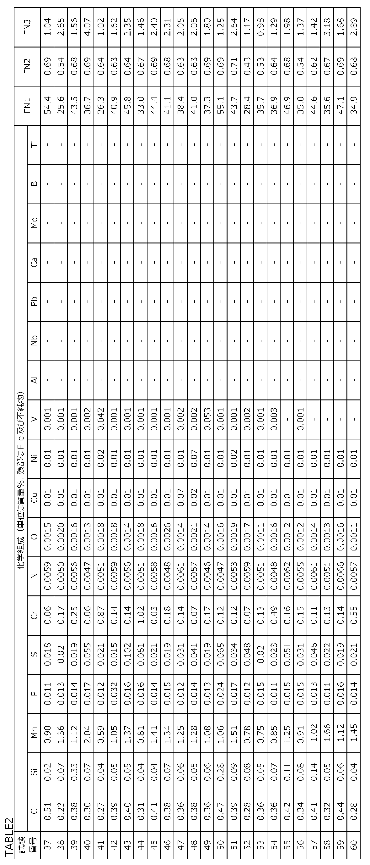
表1及び表2中の「-」は、対応する元素含有量が検出限界未満であったことを意味する。二次精錬での脱酸工程において、試験番号2~30、32~53、58~60では、溶鋼にSiを添加した後、Mn源であるFe-Mn合金(Fe-Mn合金の酸素含有量は1.0at%以下)を添加した(表3及び表4中の「添加順」欄に「Si→Mn」で表記)。試験番号1及び31では、二次精錬での脱酸工程において、溶鋼にSi及びAlを添加した後、Mn源であるFe-Mn合金(Fe-Mn合金の酸素含有量は1.0at%以下)を添加した(表3及び表4中の「添加順」欄に「SiAl→Mn」で表記)。試験番号54及び55では、脱酸工程において、溶鋼に上記Fe-Mn合金(Fe-Mn合金の酸素含有量は1.0at%以下)を添加した後、Siを添加した(表3及び表4中の「添加順」欄に「Mn→Si」で表記)。試験番号56及び57では、脱酸工程において、溶鋼にSiを添加した後、Mn源であるFe-Mn合金(酸素含有量が1.0at%超)を添加した(表3及び表4中の「添加順」欄に「Si→Mn+」で表記)。
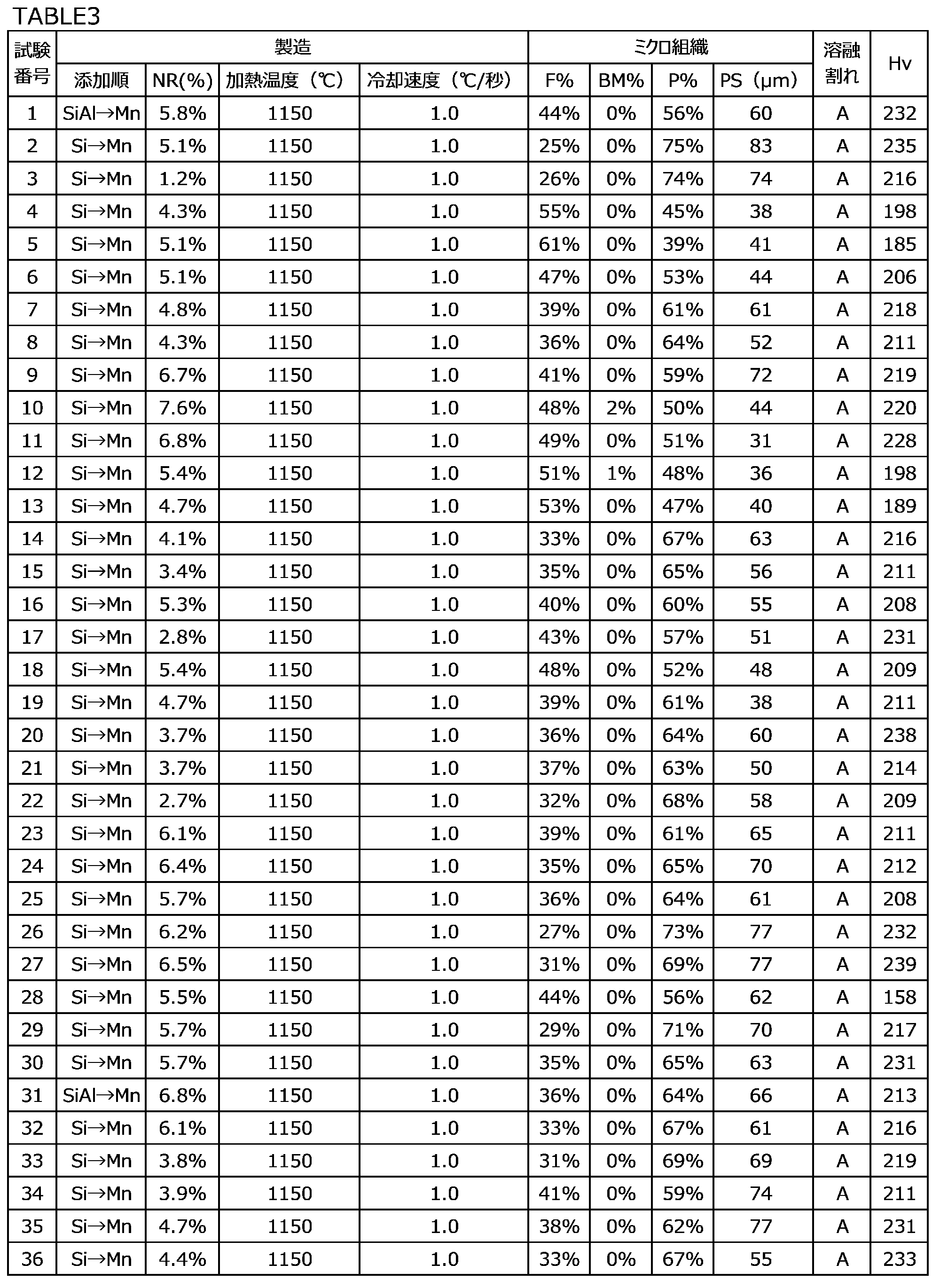
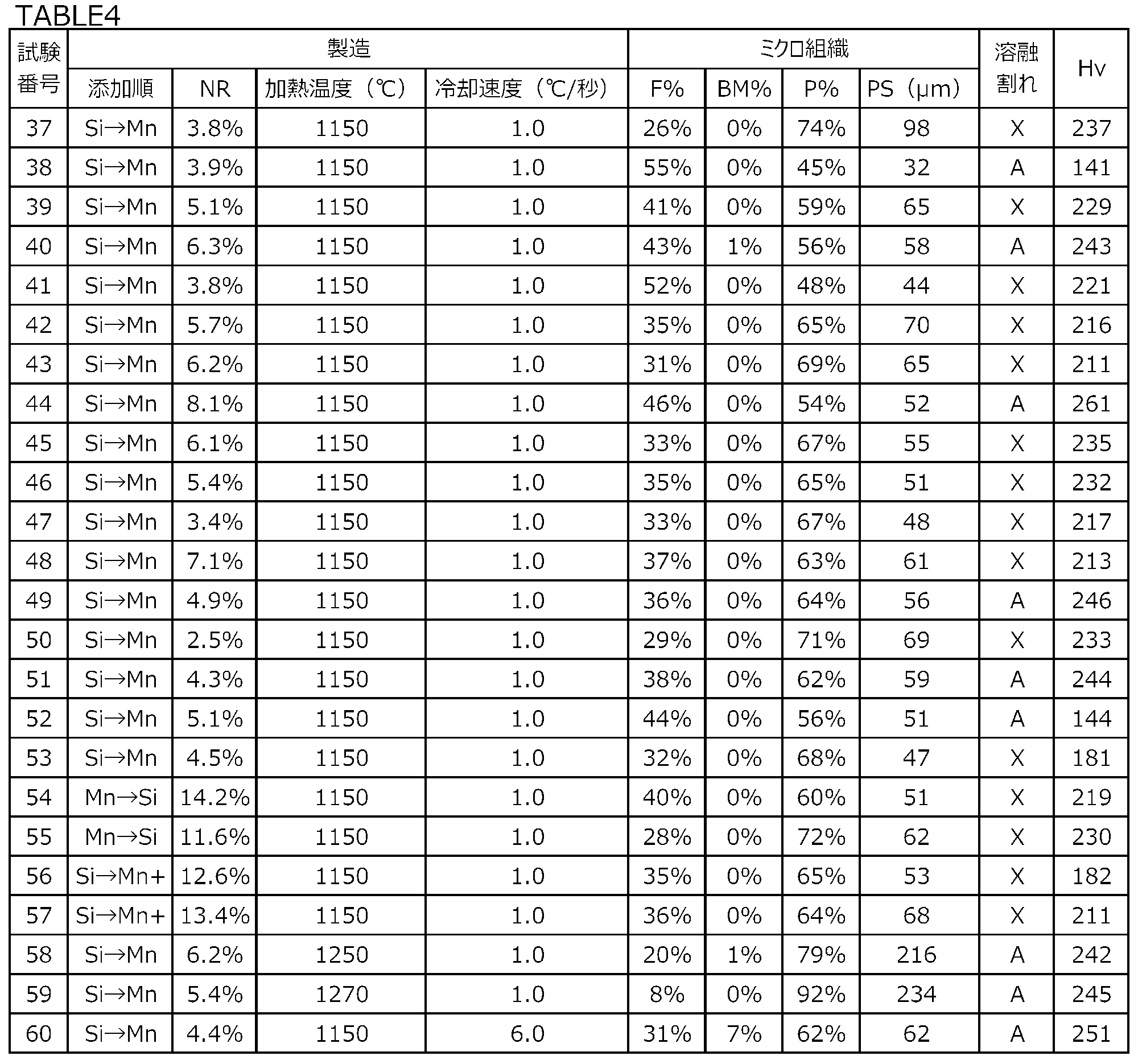
製造された溶鋼を用いて、連続鋳造法により300mm×400mmの横断面を有する鋳片(ブルーム)を製造した。鋳片に対して粗圧延工程を実施して、横断面が180mm×180mmのビレットを製造した。粗圧延工程での鋳片の加熱温度はいずれの試験番号においても、1150℃であった。
粗圧延工程後のビレットに対して、仕上げ圧延を実施して、直径80mmの棒鋼(高周波焼入用鋼)を製造した。仕上げ圧延工程での加熱温度を表3及び表4に示す。具体的には、試験番号1~57、及び、60では、仕上げ圧延工程での加熱温度が1150℃であった。試験番号58では、仕上げ圧延工程での加熱温度が1250℃であった。試験番号59では、仕上げ圧延工程での加熱温度が1270℃であった。
さらに各試験番号の仕上げ圧延後の鋼材を、表3及び表4に示す冷却速度(℃/秒)で冷却した。具体的には、試験番号1~59では、冷却速度が1.0℃/秒であった。試験番号60では、冷却速度が6.0℃/秒であった。以上の製造工程により、高周波焼入用鋼(棒鋼)を製造した。
[溶融割れ評価試験]
各試験番号の鋼の長手方向に対して垂直な断面のR/2位置(棒鋼の長手方向に垂直な断面における、棒鋼の中心軸と外表面とを結ぶ直線(半径R)の中央位置)から、幅10mm、厚さ3mm、長さ10mmの試験片を機械加工により作製した。試験片の長さ方向は、棒鋼の長手方向と平行であった。また、試験片の長手方向に平行な中心軸が、R/2位置と一致した。
各試験番号の鋼の長手方向に対して垂直な断面のR/2位置(棒鋼の長手方向に垂直な断面における、棒鋼の中心軸と外表面とを結ぶ直線(半径R)の中央位置)から、幅10mm、厚さ3mm、長さ10mmの試験片を機械加工により作製した。試験片の長さ方向は、棒鋼の長手方向と平行であった。また、試験片の長手方向に平行な中心軸が、R/2位置と一致した。
富士電波工機株式会社製の試験装置(商品名「熱サイクル試験装置」)を用いて、上記試験片に対して、高周波焼入れの模擬試験を実施した。具体的には、高周波コイルを用いて試験片を100℃/秒の昇温速度で1380℃まで加熱した。そして、試験片を1380℃で10秒間保持した。その後、試験片を水冷した。
水冷後の試験片の長手方向に対して垂直な断面(観察面)を機械研磨した。機械研磨後の観察面をピクラール試薬にて腐食した。腐食された観察面を400倍の光学顕微鏡で観察し、溶融割れの有無を目視で確認した。観察面は、250μm×400μmであった。
図5は、溶融割れが発生したミクロ組織写真画像例であり、図6は溶融割れが発生しなかったミクロ組織写真画像例である。
観察面の組織において、粒界において5μm以上の幅で明瞭に腐食されている領域が観察される場合(たとえば、図5中の符号10)、溶融割れが発生したと判断した(表1及び表2中の「溶融割れ」欄において、「X」で示す)。一方、図6のように、粒界に腐食領域が観察されない場合、溶融割れが発生しなかったと判断した(表1及び表2中の「溶融割れ」欄において、「A」で示す)。図5及び図6に示すとおり、溶融割れの有無の確認は可能であった。
[ビッカース硬さ試験]
各試験番号の鋼に対して、熱間鍛造後の冷却を模擬する熱処理を実施した。具体的には、棒鋼を1100℃に加熱して30分保持した。その後、棒鋼を大気中で放冷した。熱処理後の棒鋼の長手方向に対して垂直な断面のR/2位置を中心としたR/2部(10mm×10mm)において、JISZ2244(2009)に準拠して、3点のビッカース硬さを測定した。このときの試験力を9.8Nとした。求めた3点の硬さの平均値を、「Hv硬さ」と定義した。
各試験番号の鋼に対して、熱間鍛造後の冷却を模擬する熱処理を実施した。具体的には、棒鋼を1100℃に加熱して30分保持した。その後、棒鋼を大気中で放冷した。熱処理後の棒鋼の長手方向に対して垂直な断面のR/2位置を中心としたR/2部(10mm×10mm)において、JISZ2244(2009)に準拠して、3点のビッカース硬さを測定した。このときの試験力を9.8Nとした。求めた3点の硬さの平均値を、「Hv硬さ」と定義した。
内部硬さであるHv硬さが150以上であれば、熱間鍛造後の機械構造用部品において、十分な疲労強度が得られることが判明している。一方、Hv硬さが240を超えれば、被削性が低いと判断した。表3及び表4の「Hv」欄に、得られたビッカース硬さ(Hv)を示す。
[Mn酸化物個数比NR測定試験]
各試験番号の鋼のMn酸化物個数比NRを次の方法で測定した。各試験番号の棒鋼のR/2位置(棒鋼の長手方向に垂直な断面における、棒鋼の中心軸と外表面とを結ぶ直線(半径R)の中央位置)を中心とした、10mm×15mmの矩形状の観察面を含むサンプルを採取した。採取されたサンプルの観察面を鏡面研磨した。エネルギー分散型X線分析装置(EDX)を備えた走査型電子顕微鏡を用いて鏡面研磨された観察面を二次電子像にて観察し、コントラストに基づいて、観察視野内の色の異なる部分を介在物と認定した。そして、認定された各介在物の成分を、介在物の中心点においてビーム径10μmで点分析した。そして、観察面内の酸化物、及び、Mn酸化物を特定した。具体的には、観察面内の介在物のうち、酸素を質量%で20.0%以上含有するものを、「酸化物」と特定した。また、酸化物のうち、Mnを質量%で10.0%以上含有するものを、「Mn酸化物」と特定した。総面積4.8×106μm2の観察面で、特定された酸化物の総個数の、Mn酸化物の総個数に対する比(=Mn酸化物の個数/酸化物の個数×100)を、Mn酸化物個数比NR(%)と定義した。得られたMn酸化物個数比NRを、表3及び表4中の「NR」欄に示す。
各試験番号の鋼のMn酸化物個数比NRを次の方法で測定した。各試験番号の棒鋼のR/2位置(棒鋼の長手方向に垂直な断面における、棒鋼の中心軸と外表面とを結ぶ直線(半径R)の中央位置)を中心とした、10mm×15mmの矩形状の観察面を含むサンプルを採取した。採取されたサンプルの観察面を鏡面研磨した。エネルギー分散型X線分析装置(EDX)を備えた走査型電子顕微鏡を用いて鏡面研磨された観察面を二次電子像にて観察し、コントラストに基づいて、観察視野内の色の異なる部分を介在物と認定した。そして、認定された各介在物の成分を、介在物の中心点においてビーム径10μmで点分析した。そして、観察面内の酸化物、及び、Mn酸化物を特定した。具体的には、観察面内の介在物のうち、酸素を質量%で20.0%以上含有するものを、「酸化物」と特定した。また、酸化物のうち、Mnを質量%で10.0%以上含有するものを、「Mn酸化物」と特定した。総面積4.8×106μm2の観察面で、特定された酸化物の総個数の、Mn酸化物の総個数に対する比(=Mn酸化物の個数/酸化物の個数×100)を、Mn酸化物個数比NR(%)と定義した。得られたMn酸化物個数比NRを、表3及び表4中の「NR」欄に示す。
[ミクロ組織観察試験]
各試験番号の鋼のミクロ組織における、フェライト面積率、低温変態相面積率(ベイナイト及びマルテンサイトの総面積率)、及び、パーライト面積率を次の方法で求めた。各試験番号の鋼のR/2位置を中心としてサンプルを採取した。採取されたサンプルのうち、鋼の長手方向(軸方向)に垂直な面を観察面とした。観察面を研磨した後、サンプルの観察面をナイタール腐食液を用いてエッチングした。エッチングされた観察面を、100倍の光学顕微鏡にて観察して、任意の5視野の写真画像を生成した。各視野のサイズは800μm×600μmであった。
各試験番号の鋼のミクロ組織における、フェライト面積率、低温変態相面積率(ベイナイト及びマルテンサイトの総面積率)、及び、パーライト面積率を次の方法で求めた。各試験番号の鋼のR/2位置を中心としてサンプルを採取した。採取されたサンプルのうち、鋼の長手方向(軸方向)に垂直な面を観察面とした。観察面を研磨した後、サンプルの観察面をナイタール腐食液を用いてエッチングした。エッチングされた観察面を、100倍の光学顕微鏡にて観察して、任意の5視野の写真画像を生成した。各視野のサイズは800μm×600μmであった。
各視野において、フェライト、パーライト、及び、低温変態相(マルテンサイト及びベイナイト)を、コントラストに基づいて特定した。各視野において、黒い線に囲まれた白く均一に観察される領域を「フェライト」と判断した。さらに、各視野において、層状に観察される領域を「パーライト」と判断した。さらに、各視野において、粒内組織が微細で黒く観察される領域を「低温変態相(ベイナイト及びマルテンサイト)」と判断した。
5視野のフェライトの総面積(μm2)、及び、低温変態相(ベイナイト及びマルテンサイト)の総面積(μm2)を求めた。そして、フェライトの総面積の、5視野の総面積に対する比率を、フェライト面積率(%)と定義した。また、低温変態相(ベイナイト及びマルテンサイト)の面積の、5視野の総面積に対する比率を、低温変態相(ベイナイト及びマルテンサイト)の面積率(%)と定義した。なお、5視野のパーライトの総面積の、5視野の総面積に対する比率を、パーライト面積率(%)と定義した。表3及び表4中の「ミクロ組織」欄の「F%」欄にフェライト面積率を示し、「BM%」欄に低温変態相面積率を示し、「P%」欄にパーライト面積率とを示す。
[パーライト領域の幅の測定試験]
さらに、各試験番号の鋼のパーライト領域の幅を、上述の線分法により求めた。具体的には、上述のミクロ組織観察試験で作成した5視野の写真画像を用いた。各写真画像において、長辺において100μmピッチで線分R1~R7を配置し、短辺において100μmピッチで線分C1~C5を配置した。そして、線分R1~R7及びC1~C5の各々において、線分と重複したパーライト領域の平均幅を求めた。具体的には、各線分において、パーライト領域の幅を次式により求めた。
線分でのパーライト領域の幅=線分と重複するパーライト領域の重複長さの合計/各線分と重複するパーライト領域の総個数
さらに、各試験番号の鋼のパーライト領域の幅を、上述の線分法により求めた。具体的には、上述のミクロ組織観察試験で作成した5視野の写真画像を用いた。各写真画像において、長辺において100μmピッチで線分R1~R7を配置し、短辺において100μmピッチで線分C1~C5を配置した。そして、線分R1~R7及びC1~C5の各々において、線分と重複したパーライト領域の平均幅を求めた。具体的には、各線分において、パーライト領域の幅を次式により求めた。
線分でのパーライト領域の幅=線分と重複するパーライト領域の重複長さの合計/各線分と重複するパーライト領域の総個数
各線分R1~R7及びC1~C5の各々において、上記式に基づいてパーライト領域の幅を求めた。5視野の写真画像全てにおいて、各線分でのパーライト領域の幅を求めた。そして、各線分でのパーライト領域の幅の平均を、当該試験番号の鋼でのパーライト領域の幅(μm)と定義した。表3及び表4の「PS(μm)」欄に、パーライト領域の幅(μm)を示す。
[試験結果]
試験結果を表3及び表4に示す。試験番号1~36では、化学組成が適切であり、FN1~FN3も適切であった。さらに、製造条件が適切であったため、Mn酸化物個数比NRが10.0%以下であった。そのため、溶融割れは観察されなかった。さらに、ミクロ組織において、フェライトの面積率は10%以上であり、ベイナイト及びマルテンサイトの総面積率が5%以下であり、残部はパーライトであり、パーライト領域の幅は200μm以下であった。そのため、ビッカース硬さHvが150~240の範囲内であり、十分な疲労強度及び被削性が得られることが予想できた。
試験結果を表3及び表4に示す。試験番号1~36では、化学組成が適切であり、FN1~FN3も適切であった。さらに、製造条件が適切であったため、Mn酸化物個数比NRが10.0%以下であった。そのため、溶融割れは観察されなかった。さらに、ミクロ組織において、フェライトの面積率は10%以上であり、ベイナイト及びマルテンサイトの総面積率が5%以下であり、残部はパーライトであり、パーライト領域の幅は200μm以下であった。そのため、ビッカース硬さHvが150~240の範囲内であり、十分な疲労強度及び被削性が得られることが予想できた。
一方、試験番号37では、C含有量が高すぎた。そのため、溶融割れ評価試験において、溶融割れの発生が確認された。
試験番号38では、C含有量が低すぎた。そのため、ビッカース硬さHvが150未満であり、十分な疲労強度が得られないことが予想できた。
試験番号39では、Si含有量が高すぎた。そのため、溶融割れ評価試験において、溶融割れの発生が確認された。
試験番号40では、Mn含有量が高すぎた。そのため、ビッカース硬さHvが240を超え、十分な被削性が得られないことが予想できた。
試験番号41では、Mn含有量が低すぎた。そのため、溶融割れ評価試験において、溶融割れの発生が確認された。
試験番号42では、P含有量が高すぎた。そのため、溶融割れ評価試験において、溶融割れの発生が確認された。
試験番号43では、S含有量が高すぎた。そのため、溶融割れ評価試験において、溶融割れの発生が確認された。
試験番号44では、Cr含有量が高すぎた。そのため、ビッカース硬さHvが240を超え、十分な被削性が得られないことが予想できた。
試験番号45では、Cr含有量が低すぎた。そのため、溶融割れ評価試験において、溶融割れの発生が確認された。
試験番号46では、O含有量が高すぎた。そのため、溶融割れ評価試験において、溶融割れの発生が確認された。
試験番号47では、Cu含有量が高すぎた。そのため、溶融割れ評価試験において、溶融割れの発生が確認された。
試験番号48では、Ni含有量が高すぎた。そのため、溶融割れ評価試験において、溶融割れの発生が確認された。
試験番号49では、V含有量が高すぎた。そのため、ビッカース硬さHvが240を超え、十分な被削性が得られないことが予想できた。
試験番号50では、FN1が式(1)の上限を超えた。そのため、溶融割れ評価試験において、溶融割れの発生が確認された。
試験番号51では、FN2が式(2)の上限を超えた。そのため、ビッカース硬さHvが240を超え、十分な被削性が得られないことが予想できた。
試験番号52では、FN2が式(2)の下限未満であった。そのため、ビッカース硬さHvが150未満であり、十分な疲労強度が得られないことが予想できた。
試験番号53では、FN3が式(3)の下限未満であった。そのため、溶融割れ評価試験において、溶融割れの発生が確認された。
試験番号54及び55では、二次精錬において、溶鋼にMn源を添加した後、Siを添加した。そのため、Mn酸化物個数比NRが10.0%を超えた。その結果、溶融割れが発生した。
試験番号56及び57では、二次精錬において、溶鋼にSiを添加した後、Mn源であるFe-Mn合金を添加したものの、Fe-Mn合金の酸素含有量が1.0at%を超えていた。そのため、Mn酸化物個数比NRが10.0%を超えた。その結果、溶融割れが発生した。
試験番号58及び59では、熱間加工時の仕上げ圧延工程での加熱温度が高すぎた。そのため、パーライト領域の幅が200μmを超えた。その結果、ビッカース硬さHvが240を超え、十分な被削性が得られないことが予想できた。
試験番号60では、熱間加工時の仕上げ圧延工程での冷却速度が速すぎた。そのため、ミクロ組織において、低温変態相の面積率が高すぎた。その結果、ビッカース硬さHvが240を超え、十分な被削性が得られないことが予想できた。
以上、本発明の実施の形態を説明した。しかしながら、上述した実施の形態は本発明を実施するための例示に過ぎない。したがって、本発明は上述した実施の形態に限定されることなく、その趣旨を逸脱しない範囲内で上述した実施の形態を適宜変更して実施することができる。
本実施形態の鋼は、高周波焼入れされて製造される機械構造用部品用途に広く適用可能である。特に、本実施形態の鋼は、鋼を用いて機械構造用部品を製造する製造工程において、熱間鍛造後に高周波焼入れされる場合に好適である。
1 フィレットR部
2 クランクシャフトのエッジ部
10 溶融割れ
2 クランクシャフトのエッジ部
10 溶融割れ
Claims (2)
- 化学組成が、質量%で、
C:0.25~0.50%、
Si:0.01~0.30%未満、
Mn:0.60~2.00%、
P:0.030%以下、
S:0.010超~0.095%、
Cr:0.05~1.00%、
N:0.0040~0.0200%、
O:0.0024%以下、
Cu:0.05%以下、
Ni:0.05%以下、
V:0~0.050%未満、
Al:0~0.040%、
Nb:0~0.020%、
Pb:0~0.30%、
Ca:0~0.0100%、
Mo:0~0.20%、
B:0~0.0030%、
Ti:0~0.020%、及び、
残部がFe及び不純物、からなり、
式(1)で定義されるFN1が55.0以下であり、
式(2)で定義されるFN2が0.45~0.70未満であり、
式(3)で定義されるFN3が1.00以上であり、
鋼中において、20.0質量%以上の酸素を含有する酸化物の個数に対する、20.0質量%以上の酸素及び10.0質量%以上のMnを含有するMn酸化物の個数の割合は、10.0%以下であり、
ミクロ組織において、
フェライトの面積率は10%以上であり、ベイナイト及びマルテンサイトの総面積率が5%以下であり、残部はパーライトであり、
パーライト領域の幅は200μm以下である、
鋼。
FN1=80C2+55C+13Si+4.8Mn+30P+30S+1.5Cr (1)
FN2=C+(Si/10)+(Mn/5)-(5S/7)+(5Cr/22)+1.65V (2)
FN3=-2C-Si+2.33Mn+0.26Cr+V-1.5Cu-1.5Ni (3)
ここで、式(1)~式(3)中の各元素記号には、対応する元素の含有量(質量%)が代入される。 - 請求項1に記載の鋼であって、
前記化学組成は、
V:0.010~0.050%未満、
Al:0.005~0.040%、
Nb:0.005~0.020%、
Pb:0.10~0.30%、
Ca:0.0010~0.0100%、
Mo:0.05~0.20%、
B:0.0005~0.0030%、及び、
Ti:0.005~0.020%、
からなる群から選択される1元素又は2元素以上を含有する、
鋼。
Priority Applications (2)
| Application Number | Priority Date | Filing Date | Title |
|---|---|---|---|
| JP2019541465A JP6673535B1 (ja) | 2019-03-28 | 2019-03-28 | 高周波焼入れが実施される鋼 |
| PCT/JP2019/013563 WO2020194653A1 (ja) | 2019-03-28 | 2019-03-28 | 高周波焼入れが実施される鋼 |
Applications Claiming Priority (1)
| Application Number | Priority Date | Filing Date | Title |
|---|---|---|---|
| PCT/JP2019/013563 WO2020194653A1 (ja) | 2019-03-28 | 2019-03-28 | 高周波焼入れが実施される鋼 |
Publications (1)
| Publication Number | Publication Date |
|---|---|
| WO2020194653A1 true WO2020194653A1 (ja) | 2020-10-01 |
Family
ID=70000912
Family Applications (1)
| Application Number | Title | Priority Date | Filing Date |
|---|---|---|---|
| PCT/JP2019/013563 Ceased WO2020194653A1 (ja) | 2019-03-28 | 2019-03-28 | 高周波焼入れが実施される鋼 |
Country Status (2)
| Country | Link |
|---|---|
| JP (1) | JP6673535B1 (ja) |
| WO (1) | WO2020194653A1 (ja) |
Cited By (2)
| Publication number | Priority date | Publication date | Assignee | Title |
|---|---|---|---|---|
| CN113151743A (zh) * | 2021-04-20 | 2021-07-23 | 中天钢铁集团有限公司 | 一种低马氏体含量免调质冷镦钢盘条的制造方法及其应用 |
| CN117980518A (zh) * | 2021-09-24 | 2024-05-03 | 日本制铁株式会社 | 钢材 |
Families Citing this family (1)
| Publication number | Priority date | Publication date | Assignee | Title |
|---|---|---|---|---|
| KR102402238B1 (ko) * | 2020-08-07 | 2022-05-26 | 주식회사 포스코 | 수소 취화 저항성 및 충격 인성이 우수한 강재 및 이의 제조방법 |
Citations (6)
| Publication number | Priority date | Publication date | Assignee | Title |
|---|---|---|---|---|
| JP2006291237A (ja) * | 2005-04-05 | 2006-10-26 | Kobe Steel Ltd | 冷間鍛造性と切削性に優れた機械構造用鋼 |
| JP2009270160A (ja) * | 2008-05-08 | 2009-11-19 | Sumitomo Metal Ind Ltd | 軟窒化用鋼材の製造方法 |
| JP2010013729A (ja) * | 2008-06-06 | 2010-01-21 | Sumitomo Metal Ind Ltd | 軟窒化用鋼、軟窒化用鋼材およびクランクシャフト |
| JP2010202913A (ja) * | 2009-03-02 | 2010-09-16 | Nippon Steel Corp | 高強度鋼線用線材、高強度鋼線及びこれらの製造方法 |
| WO2017188284A1 (ja) * | 2016-04-26 | 2017-11-02 | 新日鐵住金株式会社 | 高周波焼入れ用非調質鋼 |
| WO2018016502A1 (ja) * | 2016-07-19 | 2018-01-25 | 新日鐵住金株式会社 | 高周波焼入れ用鋼 |
-
2019
- 2019-03-28 WO PCT/JP2019/013563 patent/WO2020194653A1/ja not_active Ceased
- 2019-03-28 JP JP2019541465A patent/JP6673535B1/ja active Active
Patent Citations (6)
| Publication number | Priority date | Publication date | Assignee | Title |
|---|---|---|---|---|
| JP2006291237A (ja) * | 2005-04-05 | 2006-10-26 | Kobe Steel Ltd | 冷間鍛造性と切削性に優れた機械構造用鋼 |
| JP2009270160A (ja) * | 2008-05-08 | 2009-11-19 | Sumitomo Metal Ind Ltd | 軟窒化用鋼材の製造方法 |
| JP2010013729A (ja) * | 2008-06-06 | 2010-01-21 | Sumitomo Metal Ind Ltd | 軟窒化用鋼、軟窒化用鋼材およびクランクシャフト |
| JP2010202913A (ja) * | 2009-03-02 | 2010-09-16 | Nippon Steel Corp | 高強度鋼線用線材、高強度鋼線及びこれらの製造方法 |
| WO2017188284A1 (ja) * | 2016-04-26 | 2017-11-02 | 新日鐵住金株式会社 | 高周波焼入れ用非調質鋼 |
| WO2018016502A1 (ja) * | 2016-07-19 | 2018-01-25 | 新日鐵住金株式会社 | 高周波焼入れ用鋼 |
Cited By (2)
| Publication number | Priority date | Publication date | Assignee | Title |
|---|---|---|---|---|
| CN113151743A (zh) * | 2021-04-20 | 2021-07-23 | 中天钢铁集团有限公司 | 一种低马氏体含量免调质冷镦钢盘条的制造方法及其应用 |
| CN117980518A (zh) * | 2021-09-24 | 2024-05-03 | 日本制铁株式会社 | 钢材 |
Also Published As
| Publication number | Publication date |
|---|---|
| JPWO2020194653A1 (ja) | 2021-04-30 |
| JP6673535B1 (ja) | 2020-03-25 |
Similar Documents
| Publication | Publication Date | Title |
|---|---|---|
| JP6245271B2 (ja) | 棒鋼 | |
| CN109563578B (zh) | 高频淬火用钢 | |
| WO2011158782A1 (ja) | 鍛造クランクシャフト | |
| JP7168003B2 (ja) | 鋼材 | |
| US10801091B2 (en) | Steel for induction hardening | |
| US20190300993A1 (en) | Steel for Induction Hardening | |
| KR20190028781A (ko) | 고주파 담금질용 강 | |
| KR20190028757A (ko) | 고주파 담금질용 강 | |
| CN111684094A (zh) | 进行渗碳处理的部件用钢材 | |
| JP6844943B2 (ja) | 高周波焼入れ用非調質鋼 | |
| WO2023223694A1 (ja) | 鋼板およびその製造方法 | |
| JP6673535B1 (ja) | 高周波焼入れが実施される鋼 | |
| US11447849B2 (en) | Non-heat treated steel for induction hardening | |
| JP7099553B2 (ja) | 鋼材及び部品 | |
| JP7140274B2 (ja) | 鋼軸部品 | |
| JP7367896B1 (ja) | 鋼板およびその製造方法 | |
| JP2024155202A (ja) | 継目無鋼管 | |
| JPH11106866A (ja) | 粗大粒防止特性に優れた肌焼鋼とその製造方法 | |
| JP7205067B2 (ja) | 高周波焼入れ用非調質鋼 | |
| JP7205066B2 (ja) | 高周波焼入れ用非調質鋼 | |
| WO2026053866A1 (ja) | 継目無鋼管およびその製造方法 | |
| WO2026088923A1 (ja) | 耐割れ性に優れた肌焼鋼 | |
| JP2024147332A (ja) | 鋼材 | |
| WO2025258443A1 (ja) | 鋼およびその製造方法 |
Legal Events
| Date | Code | Title | Description |
|---|---|---|---|
| ENP | Entry into the national phase |
Ref document number: 2019541465 Country of ref document: JP Kind code of ref document: A |
|
| 121 | Ep: the epo has been informed by wipo that ep was designated in this application |
Ref document number: 19920751 Country of ref document: EP Kind code of ref document: A1 |
|
| NENP | Non-entry into the national phase |
Ref country code: DE |
|
| 122 | Ep: pct application non-entry in european phase |
Ref document number: 19920751 Country of ref document: EP Kind code of ref document: A1 |