WO2020189765A1 - コイル状線材ばらし方法及びコイル状線材のばらし作業台 - Google Patents
コイル状線材ばらし方法及びコイル状線材のばらし作業台 Download PDFInfo
- Publication number
- WO2020189765A1 WO2020189765A1 PCT/JP2020/012355 JP2020012355W WO2020189765A1 WO 2020189765 A1 WO2020189765 A1 WO 2020189765A1 JP 2020012355 W JP2020012355 W JP 2020012355W WO 2020189765 A1 WO2020189765 A1 WO 2020189765A1
- Authority
- WO
- WIPO (PCT)
- Prior art keywords
- coiled wire
- coil
- rod
- disassembling
- workbench
- Prior art date
- Legal status (The legal status is an assumption and is not a legal conclusion. Google has not performed a legal analysis and makes no representation as to the accuracy of the status listed.)
- Ceased
Links
Images





Classifications
-
- C—CHEMISTRY; METALLURGY
- C23—COATING METALLIC MATERIAL; COATING MATERIAL WITH METALLIC MATERIAL; CHEMICAL SURFACE TREATMENT; DIFFUSION TREATMENT OF METALLIC MATERIAL; COATING BY VACUUM EVAPORATION, BY SPUTTERING, BY ION IMPLANTATION OR BY CHEMICAL VAPOUR DEPOSITION, IN GENERAL; INHIBITING CORROSION OF METALLIC MATERIAL OR INCRUSTATION IN GENERAL
- C23G—CLEANING OR DE-GREASING OF METALLIC MATERIAL BY CHEMICAL METHODS OTHER THAN ELECTROLYSIS
- C23G1/00—Cleaning or pickling metallic material with solutions or molten salts
- C23G1/02—Cleaning or pickling metallic material with solutions or molten salts with acid solutions
-
- C—CHEMISTRY; METALLURGY
- C23—COATING METALLIC MATERIAL; COATING MATERIAL WITH METALLIC MATERIAL; CHEMICAL SURFACE TREATMENT; DIFFUSION TREATMENT OF METALLIC MATERIAL; COATING BY VACUUM EVAPORATION, BY SPUTTERING, BY ION IMPLANTATION OR BY CHEMICAL VAPOUR DEPOSITION, IN GENERAL; INHIBITING CORROSION OF METALLIC MATERIAL OR INCRUSTATION IN GENERAL
- C23G—CLEANING OR DE-GREASING OF METALLIC MATERIAL BY CHEMICAL METHODS OTHER THAN ELECTROLYSIS
- C23G3/00—Apparatus for cleaning or pickling metallic material
Definitions
- the present invention relates to a coiled wire disassembling method and a coiled wire disassembling workbench used in this method.
- the coiled wire is formed by winding one metal wire into a coil, and when the winding shape for one circumference is called a coil part, the coil parts having the same coil diameter are in close contact with each other in the axial direction, and the coil diameter is formed. The coil portions are formed in close contact with each other in the radial direction.
- the coiled wire is pickled and coated while being suspended from a horizontally extending hanging rod. In the pickling treatment, the coiled wire is immersed in a strongly acidic cleaning solution and pickled to remove the scale adhering to the surface. Further, in the coating treatment, the coiled wire is immersed in a required coating tank to form a coating on the surface.
- the coiled wire is hung on the horizontal rod, the movable rod is inserted into the coiled wire, the movable rod is raised higher than the horizontal rod, and the coiled wire is raised on the movable rod. Put it on. Then, the movable rod is lowered and raised higher than the horizontal rod by repeating a rectangular wavy motion to slightly divide the coiled wire rod onto the horizontal rod and hang it, and then vibrate the horizontal rod.
- the coiled wire disassembling device of Patent Document 1 is a rectangle composed of a horizontal rod that supports the coiled wire in a cantilever shape, a pedestal provided with a vibrator that vibrates the horizontal rod, and ascending, retreating, descending, and retreating. It is equipped with a cantilever movable rod that repeats wavy movements.
- the coil unwinding device of Patent Document 2 includes a coil hanger and a pedestal for supporting the coil suspended and held by the coil hanger, and a method of extending a coil wire rod on the coil receiving surface of the pedestal. There are uneven stripes that extend almost parallel to the ward. Further, in the coil unwinding method of Patent Document 2, the coil suspended and supported by the coil hanger is suspended on the coil receiving surface of the pedestal to cause the coil wire to be loosely displaced on the upper part of the coil, and then. By suspending and supporting the coil with a coil hanger, the coil wire rod is loosely displaced at the lower part of the coil.
- the coiled wire disassembling method of Patent Document 1 takes a predetermined time for the operation of moving the movable rod in a rectangular wavy motion and the operation of vibrating the horizontal rod, so that there is a problem in terms of efficiency of the coiled wire disassembling work. is there.
- the coiled wire loosening device of Patent Document 1 requires a vibrator that vibrates a horizontal rod and a mechanism that moves in a rectangular wavy shape, which causes a problem in terms of driving cost of the device.
- the wire rod coil can be easily untied, but there is a limit to the reduction of the adhesion between the coil portions after the unwinding, and the coiled wire rod. It has been required to improve the pickling treatment and the suppression of unevenness in the coating film in the adhesion portion where the scale remains after the coating treatment.
- the present invention has been made by paying attention to the unsolved problems of the above-mentioned conventional example, and provides a coiled wire disassembling method capable of reducing the device cost, and the coiled wire has a large diameter.
- a hanging rod is inserted into the inner circumference of the coiled wire, the coiled wire is suspended by the hanging rod, and the hanging rod is inserted.
- the coiled wire is placed on the valley-shaped surface along the direction diagonally intersecting the axis of the hanging rod in a plan view, and then the valley-shaped surface and the coiled wire are separated from each other and the hanging rod is separated. Returned the coiled wire to the suspended state.
- the coiled wire disassembling workbench according to one aspect of the present invention is a coiled wire disassembling workbench used in the coiled wire disassembling method described above, and has a valley-shaped surface on the upper surface. ..
- the present invention it is possible to provide a coiled wire disassembling method capable of reducing the device cost, and even if the coiled wire has a large diameter, the coiled wire disassembling work can be efficiently performed in a short time. It is possible to provide a workbench for disassembling the coiled wire rod that can be performed.
- FIG. 5 is a perspective view showing a state in which the coiled wire is disassembled in the coiled wire disassembling method of the embodiment and collided with the work surface of the workbench to be disassembled into a plurality of coil portions. It is a perspective view explaining the conventional method of disassembling a coiled wire rod.
- FIG. 1 is a coiled wire rod formed by winding one metal wire rod into a coil shape.
- the winding shape for one circumference of the coiled wire rod 1 is referred to as a coil portion
- the coil portions having the same coil diameter are in close contact with each other in the axial direction, and the coil portions having different coil diameters have diameters. It is in close contact with the direction.
- FIG. 1 is a coiled wire rod formed by winding one metal wire rod into a coil shape.
- the coil portions having the same coil diameter are in close contact with each other in the axial direction, and the coil portions having different coil diameters have diameters. It is in close contact with the direction.
- the suspension rod 2 is a member horizontally mounted on the elevating part of a cargo handling vehicle (not shown) moving in a factory such as a forklift, and the coiled wire 1 is inserted into the coil hole 1H of the coiled wire 1 to be inserted into the coil hole 1H. Suspended.
- FIG. 2 is a disassembling workbench 3 used for disassembling the coiled wire rod 1 suspended from the suspension rod 2.
- the disassembly workbench 3 is a metal plate having a rectangular shape in a plan view, and includes a flat bottom surface 4 installed on the floor surface of a factory and a work surface 5 formed on the opposite surface to the bottom surface 4, that is, the upper surface. ing.
- the work surface 5 is configured as a convex curved surface.
- the arc shape protruding from the bottom surface 4 with a predetermined radius of curvature R is formed as an arc surface shape continuous in the longitudinal direction (X direction in FIG. 2). That is, the work surface 5 has a convex shape with a radius of curvature R in a cross-sectional view of the disassembly workbench 3 orthogonal to the longitudinal direction.
- FIG. 3A a conventional coiled wire disassembling method using the hanging rod 2 and the disassembling workbench 3 will be described with reference to FIG.
- the suspension rod 2 on which the coiled wire 1 is suspended is arranged so that the axis P of the suspension rod 2 follows the convex curved surface of the work surface 5.
- the fact that the axis P follows the convex curved surface of the work surface 5 means that the projected line of the axis P draws an upwardly convex convex curve when the axis P is projected onto the work surface 5 from above. More specifically, the example shown in FIG. 3 will be described.
- the suspension rod 2 is arranged so that the axis P extends in the short direction (Y-axis direction in FIG. 2) of the workbench 3 and the coiled wire 1
- the lower part of the work surface 5 is located at the top 5a of the work surface 5 having an arcuate shape.
- the suspension rod 2 is lowered by the lowering operation of the elevating part of the cargo handling vehicle, and the lower end portion of the coiled wire 1 is made to collide with the work surface 5 to cause the coiled wire. It is placed on a convex curved surface that protrudes upward along the axial direction.
- the lump-shaped coiled wire rod 1 whose lower end portion collides with the work surface 5 is separated into lumps 1a, 1b ... Of a plurality of coil portions. Since each of the plurality of coil portion masses 1a, 1b ... Is placed on the arcuate surface-shaped work surface 5 with the coil holes 1H separated from the suspension rod 2, the plurality of coil portion masses 1a, 1b ... ... The upper parts of the suspension rod 2 move apart from each other in the P direction of the axis P.
- the suspension rod 2 is raised by the raising operation of the elevating part of the cargo handling vehicle, and the lumps 1a, 1b ... Of the plurality of coil parts are separated from the work surface 5 which is a convex curved surface. Let me do it. As a result, the plurality of coil portions 1a, 1b ... Are suspended from each other in a state of being separated from each other in the axis P direction of the suspension rod 2.
- the suspension rod 2 is lowered again by the lowering operation of the elevating part of the cargo handling vehicle, and the lower ends of the lumps 1a, 1b ... Of the plurality of coil parts are brought to the work surface 5. Collide. When the lower ends of the plurality of coil portions 1a, 1b ... Collide with the work surface 5, the radial overlap between the coil portions is eliminated, and the plurality of coil portions 7, 7 ... Of the same coil diameter are formed. It will be disassembled. A plurality of coil portions 7, 7 ... With the same coil diameter whose lower end portion contacts the work surface 5 having an arc surface shape are placed on the work surface 5 having an arc surface shape with the coil holes 1H separated from the suspension rod 2. Therefore, the upper side moves in a fan shape and is separated from each other in the axis P direction of the hanging rod 2.
- a horizontally extending hanging rod 2 that can be raised and lowered is inserted into the inner circumference of the coiled wire 1, and the coiled wire 1 is suspended by the hanging rod 2.
- the coil is placed on the work surface 5 which is a convex curved surface that protrudes upward along the direction parallel to the axis of the coiled wire 1 of the coiled wire suspended by the lowering operation of the hanging rod 2.
- a plurality of wires on the upper part of the shape wire 1 move apart from each other in the axis P direction of the hanging rod 2.
- the hanging rod 2 suspends the upper part of the coiled wire 1 from the inner peripheral side in a state where the wire in the upper part of the coiled wire 1 is separated. Make it a state.
- the wires located below the coiled wire 1 also move apart from each other in the axis P direction. Therefore, the disassembling work can be performed by simply placing and separating the coiled wire rod 1 on the work surface 5, and the disassembling work can be efficiently shortened.
- the disassembling workbench 3 has only a simple structure in which the work surface 5 on which the lower end portion of the coiled wire rod 1 collides is an arc surface protruding upward, it is possible to reduce the equipment cost. it can.
- the coiled wire disassembling workbench 3 has a work surface 5 having a convex curved surface protruding upward along the axial direction of the coiled wire on the upper surface. Since it has only a simple structure of having it, it is possible to reduce the equipment cost.
- the method for disassembling the coiled wire rod and the disassembling workbench for the coiled wire rod of the present invention make the adjacent coil portions 7 and 7 more closely adhere to each other without impairing the efficiency of the disassembling work as compared with the above-mentioned conventional form. This eliminates the problem and contributes to the reduction of the scale residue or the occurrence of film unevenness.
- FIGS. 4 to 7 are views showing members related to the coiled wire disassembling method and the apparatus according to the embodiment of the present invention. Since the hanging rod 2 has the same configuration as the conventional form, the same reference numerals are given and the description thereof will be omitted. 4 (a) to 4 (c) show the disassembling workbench 10 used in the embodiment of the present invention. As shown in FIG.
- the disassembling workbench 10 is a metal plate having a rectangular shape in a plan view, and has a flat bottom surface 11 installed on the floor surface of a factory and a surface opposite to the bottom surface 11, that is, It includes a work surface 12 formed on the upper surface.
- the work surface 12 extends linearly in the substantially diagonal direction of the disassembly workbench 10, and a band-shaped concave curved surface portion 13 formed by being recessed toward the bottom surface 11 along the short direction is formed.
- One side 13a of the strip-shaped concave curved surface portion 13 in the short direction is connected to the first convex curved surface portion 14 formed on the one long side 10a side of the disassembling workbench 10.
- the other side 13b of the strip-shaped concave curved surface portion 13 in the short direction is connected to the second convex curved surface portion 15 formed on the other long side 10b side of the disassembling workbench 10.
- the height of both the first convex curved surface portion 14 and the second convex curved surface portion 15 is higher than that of the strip-shaped concave curved surface portion 13, and the strip-shaped concave curved surface portion 13 is a valley-shaped surface.
- the work surface 12 is filled with different densities for each altitude division. The darker the area, the higher the altitude.
- the alternate long and short dash line Q in the figure is the position with the lowest altitude.
- the portion sandwiched between the two-dot chain lines R on both sides thereof is the strip-shaped concave curved surface 13.
- the two portions having an altitude higher than the alternate long and short dash line are the first convex curved surface portion 14 and the second convex curved surface portion 15, respectively.
- the convex curved surface protruding in the direction away from the bottom surface 11 along the short direction is the extending direction of the strip-shaped concave curved surface portion 13. It is continuous in the parallel direction.
- the second convex curved surface portion 15 also has a convex curved surface projecting in a direction away from the bottom surface 11 along the short direction, and the strip-shaped concave curved surface portion 13 extends. It is continuous in the direction parallel to the direction.
- the first convex curved surface portion 14 and the second convex curved surface portion 15 are formed in the same shape so that the rectangular center position PS of the work surface 12 is a point-symmetrical position.
- a method of disassembling the coiled wire rod according to the embodiment of the present invention using the hanging rod 2 and the disassembling workbench 10 will be described with reference to FIGS. 5 to 7.
- a hanging rod 2 for suspending and holding the coiled wire rod 1 is installed in a factory. It is arranged above the disassembly workbench 10 installed on the floor surface 6. At that time, the hanging rod 2 is arranged so that the axis P is at an intermediate position in the short direction of the workbench 10 and extends in the longitudinal direction.
- the strip-shaped concave curved surface portion 13 of the work surface 12, that is, the extending direction Q of the valley-shaped surface is positioned so as to intersect the axis P of the hanging rod 2 diagonally in a plan view.
- the suspension rod 2 is lowered by the lowering operation of the elevating part of the cargo handling vehicle, the lower part of the coiled wire rod 1 is disassembled and collided with the work surface 12 of the workbench 10, and then the coiled wire rod is placed on the work surface 12. Place 1 on it.
- the parts other than the lowest portion of the strip-shaped concave curved surface portion 13, or the coil portions 7, 7 ... That collide with the first convex curved surface portion 14 or the second convex curved surface portion 15 are further added.
- the coiled wire 1 is further lowered, it rolls down to a lower altitude on the working surface 12. Since the lowest altitude portion of the workbench 10 in the short direction is the bottom of the strip-shaped concave curved surface portion 13, as shown in FIGS. 5 (b) and 7 (b), the coiled wire rod 1 is a hanging rod 2.
- the coil portions 7, 7 ... At the respective positions in the axial direction of the above are placed at different positions in the short direction.
- the plurality of coil portions 7, 7 ... are suspended from the suspension rod 2 in a state where the adjacent coil portions 7, 7 are separated from each other by the axis P of the suspension rod 2 and are not in close contact with each other.
- a series of operations of placing the coiled wire 1 as described above on the working surface and then separating the coiled wire from the working surface is performed at least once, but this series of operations may be repeated a plurality of times.
- the coiled wire rod 1 suspended on the hanging rod 2 after being placed on the work surface 12 is a coil in which all the coil portions 7, 7 ... Are adjacent to each other. Since the portions 7 and 7 are separated from each other in the direction of the axis P of the hanging rod 2 and are not in close contact with each other, the pickling treatment and the coating treatment of the coiled wire 1 can be normally performed.
- the device cost can be reduced because it has only a simple structure in which the strip-shaped concave curved surface portion (valley-shaped surface) 13 is provided on the upper surface. be able to.
- the hanging rod 2 is inserted into the inner circumference of the coiled wire 1, the coiled wire 1 is suspended by the hanging rod 2, and the hanging rod 2 is inserted.
- the coiled wire rod 1 in the suspended state is placed on the strip-shaped concave curved surface portion (valley-shaped surface) 13 along the direction Q diagonally intersecting the axis P direction of the hanging rod 2 in a plan view.
- each coil portion 7, 7 By mounting on the strip-shaped concave curved surface portion 13, each coil portion 7, 7 ... Moves so that the direction along each axis of the coil portions 7, 7 ... Changes, so that the coil portions 7, 7 are in close contact with each other. Can be separated.
- the force for separating the coil portions 7, 7 from each other acts to shift the coil portions 7, 7 in the radial direction of the coil in the embodiment of the present invention.
- the force for separating the coil portions 7 and 7 from each other acts in the direction of pulling the coil portions 7 and 7 apart in the axial direction of the coiled wire rod 1.
- the direction of the action of the force for separating the close contact between the coil portions 7 and 7 is different from that of the above-mentioned conventional embodiment, and therefore the degree of elimination of the close contact between the adjacent coil portions 7 and 7 is high. Becomes larger.
- the strip-shaped concave curved surface portion 13 and the lower portion of the coil-shaped wire rod 1 are separated from each other, and the coil-shaped wire rod is suspended by the hanging rod 2, so that the direction along each axis of the coil portions 7, 7 ... It follows the axis P directly below and returns to the original alignment direction of the coils 7, 7 ..., but the close contact state of the coils 7, 7 ... Is improved. Therefore, the coiled wire rod 1 can be disassembled efficiently with a simple operation.
- the hanging rod 2 is lowered and the coiled wire 1 is placed on the strip-shaped concave curved surface portion 13 of the work surface 12, but the present invention is limited to this. Absent. With the hanging rod 2 stationary, the unraveling workbench 10 is raised to place the coiled wire 1 on the strip-shaped concave curved surface portion 13, and then the unraveling workbench 10 is lowered to lower the strip-shaped concave curved surface. The portion 13 and the lower portion of the coiled wire rod 1 may be separated from each other. Further, in the embodiment according to the present invention, the valley-shaped surface is the strip-shaped concave curved surface portion 13, but the present invention is not limited to this. The slope of the valley may be composed of planes.
- each coil portion 7, 7 ... Of the coiled wire rod 1 has a valley of a size to be fitted, and when the lower portion of the coiled wire rod 1 collides with the work surface 12, each coil portion 7, 7 ... ..., but it may be arranged so as to collide with the slope of the valley.
- the disassembling workbench is changed to the disassembling workbench 103 shown in FIG. 8 (conventional example 2: conventional example 2: For each of these (corresponding to Patent Document 2), 500 wire coil coils having a weight of about 2 tons were disassembled, and then pickled with hydrochloric acid.
- the disassembling workbench 103 shown in FIG. 8 has a work surface 105 having a convex curved surface that protrudes upward along the axial direction of the hanging rod 2 as a whole, and further, the work surface 105 has a convex curved surface. Concavo-convex strips 107 extending substantially parallel to the wire at the lower end of the coiled wire 1 are formed.
- the disassembling work involves a series of operations of placing the coiled wire 1 on the work surface and then separating the coiled wire from the work surface twice. went.
- the weight of each coil to be disassembled is about 2 tons.
- Rust is caused by residual scale in the pickling process.
- the rust occurrence rate was 3% in the conventional example 1 and 2.8% in the conventional example 2.
- the rust occurrence rate in the examples of the invention was 1.5%, and it was found that the scale residue could be suppressed by the embodiment of the present invention.
Landscapes
- Chemical & Material Sciences (AREA)
- Chemical Kinetics & Catalysis (AREA)
- General Chemical & Material Sciences (AREA)
- Engineering & Computer Science (AREA)
- Materials Engineering (AREA)
- Mechanical Engineering (AREA)
- Metallurgy (AREA)
- Organic Chemistry (AREA)
- Cleaning And De-Greasing Of Metallic Materials By Chemical Methods (AREA)
- Wire Processing (AREA)
Abstract
コイル状線材(1)の内周に吊竿(2)を挿入して吊竿でコイル状線材を吊り下げ、吊竿を挿入したまま、コイル状線材を、吊竿の軸に対して平面視で斜めに交差した方向に沿う谷状の面(13)に載置し、その後谷状の面とコイル状線材とを離間させて吊竿がコイル状線材を吊り下げた状態に戻す。
Description
本発明は、コイル状線材ばらし方法及びこの方法に用いるコイル状線材のばらし作業台に関する。
コイル状線材は、1本の金属製線材をコイル状に巻回して形成され、1周分の巻き形状をコイル部と称すると、同一コイル径のコイル部同士が軸方向に密着し、コイル径が異なるコイル部同士が径方向に密着した状態で形成されている。
コイル状線材は、水平に延在した吊竿に吊り下げられながら酸洗処理、被膜処理が行われる。酸洗処理は、コイル状線材を強酸性の洗浄液中に浸漬して酸洗することで表面に付着したスケールを離脱する。また、被膜処理は、コイル状線材を所要の塗料槽に浸漬して表面に被膜を形成する。
コイル状線材は、水平に延在した吊竿に吊り下げられながら酸洗処理、被膜処理が行われる。酸洗処理は、コイル状線材を強酸性の洗浄液中に浸漬して酸洗することで表面に付着したスケールを離脱する。また、被膜処理は、コイル状線材を所要の塗料槽に浸漬して表面に被膜を形成する。
コイル状線材の酸洗処理、被膜処理を行う際には、コイル状線材の軸方向及び径方向に隣接するコイル部同士が密着しているので、密着部分に洗浄液が浸透せずにスケールが残り、或いは密着部分の被膜にむらが出来る。
このため、従来は、作業員が、吊竿に吊り下げられているコイル状線材を手でほぐし、隣接するコイル部同士が密着しないように「ほぐし作業」をしてから洗浄液槽、或いは塗料槽に沈めていた。
しかし、コイル状線材が大径の場合は、作業員によるほぐし作業は多大な労力を必要とする。そこで、支持竿に引っ掛けたコイル状線材を機械的にほぐす(ばらす)技術として、例えば特許文献1のコイル状線材ばらし方法及び装置や、特許文献2のコイル解束装置及び解束方法が提案されている。
このため、従来は、作業員が、吊竿に吊り下げられているコイル状線材を手でほぐし、隣接するコイル部同士が密着しないように「ほぐし作業」をしてから洗浄液槽、或いは塗料槽に沈めていた。
しかし、コイル状線材が大径の場合は、作業員によるほぐし作業は多大な労力を必要とする。そこで、支持竿に引っ掛けたコイル状線材を機械的にほぐす(ばらす)技術として、例えば特許文献1のコイル状線材ばらし方法及び装置や、特許文献2のコイル解束装置及び解束方法が提案されている。
特許文献1のコイル状線材ばらし方法は、水平竿にコイル状線材を吊下げるとともに、コイル状線材の中に可動竿を挿通して可動竿を水平竿より高く上げてコイル状線材を可動竿上に乗せる。そして、可動竿を下降させ、水平竿より高く上げる矩形波状運動を繰り返すことによりコイル状線材を水平竿上に少し宛分割して吊下した後、水平竿を振動させる方法である。
また、特許文献1のコイル状線材ばらし装置は、コイル状線材を片持状に支持する水平竿と、水平竿を振動させるバイブレータを設けてなる架台と、上昇、後退、下降、後退からなる矩形波状運動を繰り返す片持状の可動竿を備えている。
また、特許文献1のコイル状線材ばらし装置は、コイル状線材を片持状に支持する水平竿と、水平竿を振動させるバイブレータを設けてなる架台と、上昇、後退、下降、後退からなる矩形波状運動を繰り返す片持状の可動竿を備えている。
さらに、特許文献2のコイル解束装置は、コイル吊具と、このコイル吊具に吊り持ちされたコイルを支持する受台とを具え、受台のコイル受面に、コイル線材の延在法区とほぼ平行に延びる凹凸条がされている。また、特許文献2のコイル解束方法は、コイル吊具に吊り持ち支持したコイルを、受台のコイル受面上に吊り降ろすことで、コイルの上部にコイル線材のばらけ変位をもたらし、その後、そのコイルをコイル吊具で吊り持ち支持することで、コイルの下部にコイル線材のばらけ変位をもたらすものである。
しかし、特許文献1のコイル状線材ばらし方法は、可動竿を矩形波状運動させる動作と、水平竿を振動させる動作に所定の時間がかかるので、コイル状線材のばらし作業の効率の面で問題がある。
また、特許文献1のコイル状線材ばらし装置は、水平竿を振動させるバイブレータ、可動さが矩形波状運動を行う機構が必要であり、装置の駆動コストの面で問題がある。
特許文献2のコイル解束装置及び解束方法によれば、簡易的に線材コイルを解束することはできるものの、解束後のコイル部同士の密着の低減には限度があり、コイル状線材の酸洗処理や、被膜処理後の、スケールが残り、或いは密着部分の被膜にむらの発生抑制についても改善が求められていた。
また、特許文献1のコイル状線材ばらし装置は、水平竿を振動させるバイブレータ、可動さが矩形波状運動を行う機構が必要であり、装置の駆動コストの面で問題がある。
特許文献2のコイル解束装置及び解束方法によれば、簡易的に線材コイルを解束することはできるものの、解束後のコイル部同士の密着の低減には限度があり、コイル状線材の酸洗処理や、被膜処理後の、スケールが残り、或いは密着部分の被膜にむらの発生抑制についても改善が求められていた。
そこで、本発明は、上記従来例の未解決の課題に着目してなされたものであり、装置コストの低減化を図ることができるコイル状線材ばらし方法を提供するとともに、コイル状線材が大径であってもコイル状線材のばらし作業を短時間で効率良く行うことができるコイル状線材のばらし作業台を提供することを目的としている。
上記目的を達成するために、本発明の一態様に係るコイル状線材ばらし方法は、コイル状線材の内周に吊竿を挿入して吊竿でコイル状線材を吊り下げ、吊竿を挿入したまま、コイル状線材を、吊竿の軸に対して平面視で斜めに交差した方向に沿う谷状の面に載置し、その後、谷状の面とコイル状線材とを離間させて吊竿がコイル状線材を吊り下げた状態に戻すようにした。
また、本発明の一態様に係るコイル状線材のばらし作業台は、上述したコイル状線材ばらし方法に用いるコイル状線材のばらし作業台であって、谷状の面となる面を、上面に有する。
また、本発明の一態様に係るコイル状線材のばらし作業台は、上述したコイル状線材ばらし方法に用いるコイル状線材のばらし作業台であって、谷状の面となる面を、上面に有する。
本発明によると、装置コストの低減化を図ることができるコイル状線材ばらし方法を提供することができるとともに、コイル状線材が大径であってもコイル状線材のばらし作業を短時間で効率良く行うことができるコイル状線材のばらし作業台を提供することができる。
次に、図面を参照して、従来の形態および本発明に係る実施形態を説明する。以下の図面の記載において、同一又は類似の部分には同一又は類似の符号を付している。ただし、図面は模式的なものであり、厚みと平面寸法との関係、各層の厚みの比率、圧延機のスタンド数等は現実のものとは異なることに留意すべきである。したがって、具体的な厚みや寸法は以下の説明を参酌して判断すべきものである。また、図面相互間においても互いの寸法の関係や比率が異なる部分が含まれていることはもちろんである。
また、以下に示す本発明に係る実施形態は、本発明の技術的思想を具体化するための装置や方法を例示するものであって、本発明の技術的思想は、構成部品の材質、形状、構造、配置等を下記のものに特定するものでない。本発明の技術的思想は、特許請求の範囲に記載された請求項が規定する技術的範囲内において、種々の変更を加えることができる。
また、以下に示す本発明に係る実施形態は、本発明の技術的思想を具体化するための装置や方法を例示するものであって、本発明の技術的思想は、構成部品の材質、形状、構造、配置等を下記のものに特定するものでない。本発明の技術的思想は、特許請求の範囲に記載された請求項が規定する技術的範囲内において、種々の変更を加えることができる。
[従来のコイル状線材ばらし方法及びコイル状線材のばらし作業台]
図1及び図2は、従来のコイル状線材ばらし方法を実施する際に用いる部材を示す図である。
図1の符号1は、1本の金属製線材をコイル状に巻回して形成したコイル状線材である。ここで、コイル状線材1の1周分の巻き形状をコイル部と称すると、コイル状線材1は、同一コイル径のコイル部同士が軸方向に密着し、コイル径が異なるコイル部同士が径方向に密着した状態となっている。図1は、このコイル状線材1の内周に吊竿2を挿入し、吊竿2にコイル状線材1が吊下がった状態を表している。
吊竿2は、フォークリフトなどの工場内を移動する荷役自動車(不図示)の昇降部に水平に装着された部材であり、コイル状線材1のコイル孔1Hに挿通することでコイル状線材1を吊り下げている。
図1及び図2は、従来のコイル状線材ばらし方法を実施する際に用いる部材を示す図である。
図1の符号1は、1本の金属製線材をコイル状に巻回して形成したコイル状線材である。ここで、コイル状線材1の1周分の巻き形状をコイル部と称すると、コイル状線材1は、同一コイル径のコイル部同士が軸方向に密着し、コイル径が異なるコイル部同士が径方向に密着した状態となっている。図1は、このコイル状線材1の内周に吊竿2を挿入し、吊竿2にコイル状線材1が吊下がった状態を表している。
吊竿2は、フォークリフトなどの工場内を移動する荷役自動車(不図示)の昇降部に水平に装着された部材であり、コイル状線材1のコイル孔1Hに挿通することでコイル状線材1を吊り下げている。
図2は、吊竿2に吊り下げられているコイル状線材1のばらし作業に使用するばらし作業台3である。
ばらし作業台3は、平面視長方形状の金属板であり、工場の床面に設置される平坦な底面4と、底面4に対して逆面、すなわち上面に形成した作業面5と、を備えている。作業面5は、凸曲面として構成されている。具体的には、底面4から離間する方向に所定の曲率半径Rで突出する円弧形状が長手方向(図2中のX方向)に連続している円弧面形状として形成されている。すなわち、作業面5は、ばらし作業台3を前記長手方向に直交する断面視では、曲率半径Rの凸状になっている。
ばらし作業台3は、平面視長方形状の金属板であり、工場の床面に設置される平坦な底面4と、底面4に対して逆面、すなわち上面に形成した作業面5と、を備えている。作業面5は、凸曲面として構成されている。具体的には、底面4から離間する方向に所定の曲率半径Rで突出する円弧形状が長手方向(図2中のX方向)に連続している円弧面形状として形成されている。すなわち、作業面5は、ばらし作業台3を前記長手方向に直交する断面視では、曲率半径Rの凸状になっている。
次に、吊竿2及びばらし作業台3を使用した従来のコイル状線材ばらし方法について図3を参照して説明する。
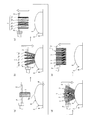
従来のコイル状線材ばらし方法は、先ず、図3(a)に示すように、コイル状線材1を吊り下げ保持している吊竿2を、工場の床面6に設置したばらし作業台3の上方に配置する。その際、コイル状線材1を吊り下げた吊竿2を、吊竿2の軸線Pが作業面5の凸曲面に沿うように配置する。軸線Pが作業面5の凸曲面に沿うとは、軸線Pを上方から作業面5に投影させた際に、軸線Pの投影線が、上方に凸な凸曲線を描くことを言う。図3に示した例について具体的に説明すると、吊竿2を、軸線Pがばらし作業台3の短尺方向(図2におけるY軸方向)に延在するように配置するとともに、コイル状線材1の下部を、円弧面形状とした作業面5の最頂部5aに位置させる。このようにすると、コイル状線材の軸方向(図3中に二点鎖線Aの延在方向)が、作業台3の短尺方向(図2におけるY軸方向)と揃うので、結果として作業面5が、コイル状線材1の軸に平行な方向に沿って上方に突出する凸曲面となる。
従来のコイル状線材ばらし方法は、先ず、図3(a)に示すように、コイル状線材1を吊り下げ保持している吊竿2を、工場の床面6に設置したばらし作業台3の上方に配置する。その際、コイル状線材1を吊り下げた吊竿2を、吊竿2の軸線Pが作業面5の凸曲面に沿うように配置する。軸線Pが作業面5の凸曲面に沿うとは、軸線Pを上方から作業面5に投影させた際に、軸線Pの投影線が、上方に凸な凸曲線を描くことを言う。図3に示した例について具体的に説明すると、吊竿2を、軸線Pがばらし作業台3の短尺方向(図2におけるY軸方向)に延在するように配置するとともに、コイル状線材1の下部を、円弧面形状とした作業面5の最頂部5aに位置させる。このようにすると、コイル状線材の軸方向(図3中に二点鎖線Aの延在方向)が、作業台3の短尺方向(図2におけるY軸方向)と揃うので、結果として作業面5が、コイル状線材1の軸に平行な方向に沿って上方に突出する凸曲面となる。
次に、図3(b)に示すように、荷役自動車の昇降部の下降動作により吊竿2を下降させていき、コイル状線材1の下端部を作業面5に衝突させ、コイル状線材の軸方向に沿って上方に突出する凸曲面に載置する状態とする。下端部が作業面5に衝突した塊状のコイル状線材1は、複数のコイル部の塊1a,1b…にばらされていく。そして、複数のコイル部の塊1a,1b…の各々は、コイル孔1Hが吊竿2から離れた状態で円弧面形状の作業面5に載っているので、複数のコイル部の塊1a,1b…の上部が、吊竿2の軸線P方向に互いに離間して移動していく。
次いで、図3(c)に示すように、荷役自動車の昇降部の上昇動作により吊竿2を上昇させていき、複数のコイル部の塊1a,1b…を凸曲面である作業面5から離間させていく。これにより、複数のコイル部の塊1a,1b…は、互いに吊竿2の軸線P方向に離れた状態で吊り下げられる。
次いで、図3(d)に示すように、再度、荷役自動車の昇降部の下降動作により吊竿2を下降させていき、複数のコイル部の塊1a,1b…の下端部を作業面5に衝突させる。複数のコイル部の塊1a,1b…は、下端部が作業面5に衝突することで、コイル部同士の径方向の重なりが解消されて、複数の同一コイル径のコイル部7,7…にばらされていく。そして、下端部が円弧面形状の作業面5に接触する複数の同一コイル径のコイル部7,7…は、コイル孔1Hが吊竿2から離れた状態で円弧面形状の作業面5に載っているので、上部側が扇状に移動し、吊竿2の軸線P方向に互いに離間していく。
そして、図3(e)に示すように、荷役自動車の昇降部の上昇動作により吊竿2を上昇させてコイル状線材1の下端部と凸曲面である作業面5から離間させていくと、コイル状線材1を構成する全てのコイル部7,7…は、隣接するコイル部7,7同士が吊竿2の軸線Pに離間して密着しない状態で、吊竿2に吊り下げられる。
[従来形態の効果]
次に、従来形態の効果について説明する。
従来実施形態では、図3(e)に示すように、吊竿2に吊り下げられたコイル状線材1について、全てのコイル部7,7…の隣接するコイル部7,7同士を吊竿2の軸線Pの方向に離間させようとしているので、酸洗処理を行う際に全てのコイル部7の全域に洗浄液が浸透してスケールが残りの低減が図れ、或いは、被膜処理を行う際にコイル部に被膜のむらの発生の抑制が図れる。
次に、従来形態の効果について説明する。
従来実施形態では、図3(e)に示すように、吊竿2に吊り下げられたコイル状線材1について、全てのコイル部7,7…の隣接するコイル部7,7同士を吊竿2の軸線Pの方向に離間させようとしているので、酸洗処理を行う際に全てのコイル部7の全域に洗浄液が浸透してスケールが残りの低減が図れ、或いは、被膜処理を行う際にコイル部に被膜のむらの発生の抑制が図れる。
また、従来形態のコイル状線材ばらし方法によると、昇降自在な水平に延在する吊竿2をコイル状線材1の内周に挿入し、吊竿2でコイル状線材1を吊り下げる。そして、その後に吊竿2の下降動作により吊り下げたコイル状線材のコイル状線材1の軸に平行な方向に沿って上方に突出する凸曲面である作業面5に載置することで、コイル状線材1の上部の複数の線材が、吊竿2の軸線P方向に互いに離間して移動していく。さらに、その後に作業面5とコイル状線材1とを離間させることで、コイル状線材1の上部における線材が離間した状態で、吊竿2がコイル状線材1の上部を内周側から吊下げる状態とする。これに伴い、コイル状線材1の下側に位置する線材も軸線P方向に互いに離間して移動していく。したがって、コイル状線材1の作業面5上への載置および離間という簡単な作業でばらし作業が行え、ばらし作業の短時間化を効率良く行うことができる。そして、ばらし作業台3は、コイル状線材1の下端部が衝突する作業面5が、上方に突出する円弧面とした簡便な構造とされているだけなので、装置コストの低減化を図ることができる。
また、従来形態のコイル状線材のばらし作業台によると、コイル状線材のばらし作業台3は、前記コイル状線材の軸方向に沿って上方に突出する凸曲面となる作業面5を、上面に有するという簡便な構造とされているだけなので、装置コストの低減化を図ることができる。
しかしながら、以上説明した従来形態においても、酸洗後のスケール残り、あるいは、被膜処理後の被膜むらの発生を皆無とするには至らない。そこで、本発明のコイル状線材のばらし方法及びコイル状線材のばらし作業台は、上記の従来形態に対して、ばらし作業の効率を損なうことなく、隣接するコイル部7,7同士の密着をより解消させ、このスケール残りあるいは被膜むらの発生の低減に貢献するものである。以下、本発明に係る実施形態について説明する。
[本発明に係る実施形態のコイル状線材ばらし方法及びコイル状線材のばらし作業台]
次に、図4から図7は、本発明に係る実施形態のコイル状線材ばらし方法及び装置に係わる部材を示す図である。なお、吊竿2は、従来形態と同一構成なので、同一符号を付して説明は省略する。
図4(a)~(c)は、本発明に係る実施形態で使用するばらし作業台10を示すものである。このばらし作業台10は、図4(a)に示すように、平面視長方形状の金属板であり、工場の床面に設置される平坦な底面11と、底面11に対して逆面、すなわち上面に形成した作業面12と、を備えている。
次に、図4から図7は、本発明に係る実施形態のコイル状線材ばらし方法及び装置に係わる部材を示す図である。なお、吊竿2は、従来形態と同一構成なので、同一符号を付して説明は省略する。
図4(a)~(c)は、本発明に係る実施形態で使用するばらし作業台10を示すものである。このばらし作業台10は、図4(a)に示すように、平面視長方形状の金属板であり、工場の床面に設置される平坦な底面11と、底面11に対して逆面、すなわち上面に形成した作業面12と、を備えている。
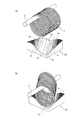
作業面12は、ばらし作業台10の略対角線方向に直線状に延在し、短尺方向に沿って底面11側に凹んで形成された帯状凹曲面部13が形成されている。この帯状凹曲面部13の短尺方向の一方側13aは、ばらし作業台10の一方の長辺10a側に形成された第1凸曲面部14に繋がっている。帯状凹曲面部13の短尺方向の他側13bは、ばらし作業台10の他方の長辺10b側に形成された第2凸曲面部15に繋がっている。第1凸曲面部14及び第2凸曲面部15は、いずれも帯状凹曲面部13よりも高さが高くなっており、帯状凹曲面部13が谷状の面となっている。図7(a)に示すばらし作業台10を用いて説明する。図7(a)においては、作業面12を標高区分毎に濃さを変えて塗り潰してある。濃く塗り潰した部分ほど標高が高いことを意味する。図中の一点鎖線Qが、標高が最も低い位置であり。その両側の二点鎖線Rで挟まれる部分が帯状凹曲面13である。二点鎖線よりも標高が高い2つの部分が、それぞれ、第1凸曲面部14、第2凸曲面部15である。
第1凸曲面部14は、図4(b)、(c)に示すように、短尺方向に沿って底面11から離間する方向に突出する凸曲面が、帯状凹曲面部13の延在方向と平行な方向に連続している。
また、第2凸曲面部15も、図4(b)、(c)に示すように、短尺方向に沿って底面11から離間する方向に突出する凸曲面が、帯状凹曲面部13の延在方向と平行な方向に連続している。
このように、第1凸曲面部14及び第2凸曲面部15は、作業面12の長方形状の中心位置PSが点対称位置となるように、同一形状に形成されている。
また、第2凸曲面部15も、図4(b)、(c)に示すように、短尺方向に沿って底面11から離間する方向に突出する凸曲面が、帯状凹曲面部13の延在方向と平行な方向に連続している。
このように、第1凸曲面部14及び第2凸曲面部15は、作業面12の長方形状の中心位置PSが点対称位置となるように、同一形状に形成されている。
次に、吊竿2及びばらし作業台10を使用した本発明に係る実施形態のコイル状線材ばらし方法について図5から図7を参照して説明する。
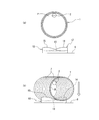
本発明に係る実施形態のコイル状線材ばらし方法は、先ず、図5(a)、図7(a)に示すように、コイル状線材1を吊り下げ保持している吊竿2を、工場の床面6に設置したばらし作業台10の上方に配置する。その際、吊竿2を、軸線Pがばらし作業台10の短尺方向の中間位置にいて長手方向に延在するように配置する。これにより、作業面12の帯状凹曲面部13すなわち谷状の面の延在方向Qは、平面視で吊竿2の軸線Pに対して斜めに交差した状態で位置する。
次に、荷役自動車の昇降部の下降動作により吊竿2を下降させていき、コイル状線材1の下部をばらし作業台10の作業面12に衝突させ、その後、作業面12上にコイル状線材1を載置する。
本発明に係る実施形態のコイル状線材ばらし方法は、先ず、図5(a)、図7(a)に示すように、コイル状線材1を吊り下げ保持している吊竿2を、工場の床面6に設置したばらし作業台10の上方に配置する。その際、吊竿2を、軸線Pがばらし作業台10の短尺方向の中間位置にいて長手方向に延在するように配置する。これにより、作業面12の帯状凹曲面部13すなわち谷状の面の延在方向Qは、平面視で吊竿2の軸線Pに対して斜めに交差した状態で位置する。
次に、荷役自動車の昇降部の下降動作により吊竿2を下降させていき、コイル状線材1の下部をばらし作業台10の作業面12に衝突させ、その後、作業面12上にコイル状線材1を載置する。
コイル状線材1の下部のうち、帯状凹曲面部13の最低位分以外の箇所、あるいは、第1凸曲面部14、或いは第2凸曲面部15に衝突したコイル部7,7…は、さらにコイル状線材1をさらに下降させると、より作業面12の中でより標高が低い場所へ転がり落ちる。作業台10の短尺方向で、最も標高が低い部分は帯状凹曲面部13の底であるため、図5(b)、図7(b)に示すように、コイル状線材1は、吊竿2の軸方向のそれぞれ位置にあるコイル部7,7…が、短尺方向に異なる位置に載置されることなる。すなわち、作業面に接触させる前段階では、吊竿2の真下に中心が位置していたコイル部7,7が、各々に帯状凹曲面部13の底(一点鎖線Q)の真上に中心が位置するように、作業台10短尺方向に移動する。この移動により、接触状態にあったコイル部7,7が、非接触状態になる。すなわち、複数のコイル部7,7…がばらされた状態となる。
次に、図6(a)に示すように、荷役自動車の昇降部の上昇動作により吊竿2を上昇させていくと、複数のコイル部7,7…の下端部が、作業面12の帯状凹曲面部13に接触した状態が解除されるので、複数のコイル部7,7…は、コイル孔1Hの頂部に吊竿2が位置した状態で、吊竿2に吊り下げられる。
この際、図6(b)に示すように、複数のコイル部7,7…は、全てのコイル中心が帯状凹曲面の底に沿った、すなわち、図4(a),図7における一点鎖線Qの真上に沿うように並ぶ状態から、吊竿2の軸線Pの真下に沿うように並ぶ状態へと替わる。そのときに、複数のコイル部7,7…は、隣接するコイル部7,7同士が吊竿2の軸線Pに離間して密着しない状態で、吊竿2に吊り下げられる。
以上のコイル状線材1を、作業面に載置し、その後コイル状線材を作業面から離間させるという一連の動作を少なくともは1回行うが、この一連の動作を複数回繰り返してもよい。
この際、図6(b)に示すように、複数のコイル部7,7…は、全てのコイル中心が帯状凹曲面の底に沿った、すなわち、図4(a),図7における一点鎖線Qの真上に沿うように並ぶ状態から、吊竿2の軸線Pの真下に沿うように並ぶ状態へと替わる。そのときに、複数のコイル部7,7…は、隣接するコイル部7,7同士が吊竿2の軸線Pに離間して密着しない状態で、吊竿2に吊り下げられる。
以上のコイル状線材1を、作業面に載置し、その後コイル状線材を作業面から離間させるという一連の動作を少なくともは1回行うが、この一連の動作を複数回繰り返してもよい。
[本発明に係る実施形態の効果]
次に、本発明に係る実施形態の効果について説明する。
図6(b)に示すように、一旦、作業面12の上に載置された後、吊竿2に吊り下げられたコイル状線材1は、全てのコイル部7,7…の隣接するコイル部7,7同士が、吊竿2の軸線Pの方向に離間して密着していないので、コイル状線材1の酸洗処理や被膜処理を正常に行うことができる。
また、本発明に係る実施形態のコイル状線材のばらし作業台によると、帯状凹曲面部(谷状の面)13を上面に有するという簡便な構造としているだけなので、装置コストの低減化を図ることができる。
次に、本発明に係る実施形態の効果について説明する。
図6(b)に示すように、一旦、作業面12の上に載置された後、吊竿2に吊り下げられたコイル状線材1は、全てのコイル部7,7…の隣接するコイル部7,7同士が、吊竿2の軸線Pの方向に離間して密着していないので、コイル状線材1の酸洗処理や被膜処理を正常に行うことができる。
また、本発明に係る実施形態のコイル状線材のばらし作業台によると、帯状凹曲面部(谷状の面)13を上面に有するという簡便な構造としているだけなので、装置コストの低減化を図ることができる。
また、本発明に係る実施形態のコイル状線材ばらし方法によると、コイル状線材1の内周に吊竿2を挿入して吊竿2でコイル状線材1を吊り下げ、吊竿2を挿入したまま、吊り下げた状態におけるコイル状線材1を、平面視で吊竿2の軸P方向に対して斜めに交差した方向Qに沿う帯状凹曲面部(谷状の面)13に載置する状態とする。この帯状凹曲面部13への載置により、コイル部7,7…の各軸の沿う方向が、変化するように各コイル部7,7…が移動するのでコイル部7,7同士の密着を離間させることができる。この際、コイル部7,7同士の密着を離間させる力は、本発明に係る実施形態においては、コイル部7,7同士をコイルの径方向をずらすように作用する。一方、上記の従来形態では、コイル部7,7同士の密着を離間させる力は、コイル部7,7同士をコイル状線材1の軸方向へ引き離す向きに作用する。本発明に係る実施形態においては、コイル部7,7同士の密着を離間させる力の作用の向きが、上記の従来実施形態とは異なるため、隣接するコイル部7,7同士の密着の解消度合がより大きくなる。
その後、帯状凹曲面部13とコイル状線材1の下部とを離間させて吊竿2でコイル状線材を吊り下げることで、コイル部7,7…の各軸の沿う方向は、吊竿2の軸Pの真下に沿うようになり、もとのコイル部7,7…の並び方向に戻るものの、コイル7,7…の密着状態は改善される。よって、簡単な作業で効率良く、コイル状線材1のばらし作業を実施できる。
なお、以上説明した本発明に係る実施形態においては、吊竿2を下降させてコイル状線材1を作業面12の帯状凹曲面部13上に載置させているが、本発明はこれに限らない。吊竿2を静止した状態として、ばらし作業台10を上昇させることで、コイル状線材1を帯状凹曲面部13上に載置し、その後、ばらし作業台10を下降させることで、帯状凹曲面部13とコイル状線材1の下部とを離間させるようにしてもよい。
また、本発明に係る実施形態においては、谷状の面を帯状凹曲面部13としているが、本発明はこれに限らない。谷の斜面が平面で構成されていてもよい。但し、コイル状線材1の各コイル部7,7…が嵌まり込む大きさの谷となっており、コイル状線材1の下部を作業面12に衝突させた際に、各コイル部7,7・・・が、谷の斜面に衝突するように配置しておけばよい。
また、本発明に係る実施形態においては、谷状の面を帯状凹曲面部13としているが、本発明はこれに限らない。谷の斜面が平面で構成されていてもよい。但し、コイル状線材1の各コイル部7,7…が嵌まり込む大きさの谷となっており、コイル状線材1の下部を作業面12に衝突させた際に、各コイル部7,7・・・が、谷の斜面に衝突するように配置しておけばよい。
[実施例]
上記した本発明に係る実施形態(発明例)、従来実施形態(従来例1)、および、従来実施形態についてばらし作業台を図8に示したばらし作業台103に変更した形態(従来例2:特許文献2相当)のそれぞれについて、1個あたりの重量が約2tonの線材コイル500個のばらし作業を実施し、その後、塩酸による酸洗処理を行った。ここで、図8に示すばらし作業台103は、作業面105が、全体的に吊竿2の軸線方向に沿って上方へ突出する凸曲面とされており、さらに、その作業面105には、コイル状線材1の下端部における線材とほぼ平行に延びる凹凸条107が形成されている。
上記した本発明に係る実施形態(発明例)、従来実施形態(従来例1)、および、従来実施形態についてばらし作業台を図8に示したばらし作業台103に変更した形態(従来例2:特許文献2相当)のそれぞれについて、1個あたりの重量が約2tonの線材コイル500個のばらし作業を実施し、その後、塩酸による酸洗処理を行った。ここで、図8に示すばらし作業台103は、作業面105が、全体的に吊竿2の軸線方向に沿って上方へ突出する凸曲面とされており、さらに、その作業面105には、コイル状線材1の下端部における線材とほぼ平行に延びる凹凸条107が形成されている。
発明例、従来例1、従来例2のいずれにおいても、ばらし作業は、コイル状線材1を、作業面に載置し、その後コイル状線材を作業面から離間させるという一連の動作を、2回行った。ばらし作業を行うコイルの重量は1個あたり約2tonである。そして、酸洗処理後のコイルについて、発錆の有無を目視確認した。発錆は酸洗処理におけるスケール残りが起因して生ずるものである。発錆の有無の確認結果より、発明例、従来例1、従来例2のそれぞれについて、発錆発生率(=発錆発生コイル数/500×100(%))を求めた。
その結果、発錆発生率が従来例1では3%、従来例2では2.8%であった。これらに対し、発明例における発錆発生率は1.5%となっており、本発明に係る実施形態によりスケール残りの抑制が可能であることがわかった。
その結果、発錆発生率が従来例1では3%、従来例2では2.8%であった。これらに対し、発明例における発錆発生率は1.5%となっており、本発明に係る実施形態によりスケール残りの抑制が可能であることがわかった。
1 コイル状線材
1H コイル孔
2 吊竿
3 ばらし作業台
4 底面
5 作業面(凸曲面)
6 工場の床面
7 コイル部
10 ばらし作業台
10a ばらし作業台の一方の長辺
10b ばらし作業台の他方の長辺
10c ばらし作業台の一方の短辺
10d ばらし作業台の一方の長辺
11 底面
12 作業面
13 帯状凹曲面部(谷状の面)
13a 帯状凹曲面部の短尺方向の一方側
13b 帯状凹曲面部の短尺方向の他側
14 第1凸曲面部
15 第2凸曲面部
P 吊竿の軸線
A コイル状線材の軸線
Q 谷状面の延在方向
1H コイル孔
2 吊竿
3 ばらし作業台
4 底面
5 作業面(凸曲面)
6 工場の床面
7 コイル部
10 ばらし作業台
10a ばらし作業台の一方の長辺
10b ばらし作業台の他方の長辺
10c ばらし作業台の一方の短辺
10d ばらし作業台の一方の長辺
11 底面
12 作業面
13 帯状凹曲面部(谷状の面)
13a 帯状凹曲面部の短尺方向の一方側
13b 帯状凹曲面部の短尺方向の他側
14 第1凸曲面部
15 第2凸曲面部
P 吊竿の軸線
A コイル状線材の軸線
Q 谷状面の延在方向
Claims (2)
- コイル状線材の内周に吊竿を挿入して該吊竿で前記コイル状線材を吊り下げ、前記吊竿を挿入したまま、前記コイル状線材を、前記吊竿の軸に対して平面視で斜めに交差した方向に沿う谷状の面に載置し、その後、該谷状の面と前記コイル状線材とを離間させて前記吊竿がコイル状線材を吊り下げた状態に戻すことを特徴とするコイル状線材ばらし方法。
- 請求項1記載のコイル状線材ばらし方法に用いるコイル状線材のばらし作業台であって、前記谷状の面となる面を、上面に有することを特徴とするコイル状線材のばらし作業台。
Priority Applications (2)
| Application Number | Priority Date | Filing Date | Title |
|---|---|---|---|
| CN202080022956.5A CN113614286B (zh) | 2019-03-19 | 2020-03-19 | 螺旋状线材拆散方法以及螺旋状线材的拆散作业台 |
| JP2021507420A JP7006836B2 (ja) | 2019-03-19 | 2020-03-19 | コイル状線材ばらし方法及びコイル状線材のばらし作業台 |
Applications Claiming Priority (2)
| Application Number | Priority Date | Filing Date | Title |
|---|---|---|---|
| JP2019051768 | 2019-03-19 | ||
| JP2019-051768 | 2019-03-19 |
Publications (1)
| Publication Number | Publication Date |
|---|---|
| WO2020189765A1 true WO2020189765A1 (ja) | 2020-09-24 |
Family
ID=72520285
Family Applications (1)
| Application Number | Title | Priority Date | Filing Date |
|---|---|---|---|
| PCT/JP2020/012355 Ceased WO2020189765A1 (ja) | 2019-03-19 | 2020-03-19 | コイル状線材ばらし方法及びコイル状線材のばらし作業台 |
Country Status (3)
| Country | Link |
|---|---|
| JP (1) | JP7006836B2 (ja) |
| CN (1) | CN113614286B (ja) |
| WO (1) | WO2020189765A1 (ja) |
Families Citing this family (1)
| Publication number | Priority date | Publication date | Assignee | Title |
|---|---|---|---|---|
| CN115354338A (zh) * | 2022-09-26 | 2022-11-18 | 海盐瑞扬新材料股份有限公司 | 线材酸洗装置 |
Citations (4)
| Publication number | Priority date | Publication date | Assignee | Title |
|---|---|---|---|---|
| JPS63235268A (ja) * | 1987-03-24 | 1988-09-30 | Kobe Steel Ltd | コイル状線材をほぐす方法 |
| JPH06207286A (ja) * | 1993-01-08 | 1994-07-26 | Daido Steel Co Ltd | コイル状線材ばらし方法および装置 |
| JPH06207285A (ja) * | 1993-01-08 | 1994-07-26 | Daido Steel Co Ltd | コイル状線材ばらし装置 |
| JPH11188446A (ja) * | 1997-12-25 | 1999-07-13 | Kawasaki Steel Corp | コイル解束装置および解束方法 |
Family Cites Families (9)
| Publication number | Priority date | Publication date | Assignee | Title |
|---|---|---|---|---|
| US4796540A (en) * | 1988-01-11 | 1989-01-10 | Cadillac Products, Inc. | Roll cradle pallet and method for fabricating the same |
| JPH08302491A (ja) * | 1995-05-10 | 1996-11-19 | Daido Steel Co Ltd | 線材コイル処理装置 |
| JP3583026B2 (ja) * | 1999-06-29 | 2004-10-27 | 株式会社神戸製鋼所 | 線材コイルのフック当たり面位置ずらし装置 |
| JP2001011673A (ja) * | 1999-07-02 | 2001-01-16 | Sanyo Special Steel Co Ltd | 線材回転装置 |
| GB0611320D0 (en) * | 2006-06-09 | 2006-07-19 | Cartwright & Sons Coach Builde | Support device for road transport vehicle |
| CN101264764A (zh) * | 2007-12-18 | 2008-09-17 | 中国南车集团株洲车辆厂 | 运输卷钢的专用装载加固装置 |
| CN104648836A (zh) * | 2013-11-25 | 2015-05-27 | 天津市力胜通预应力工程有限公司 | 一种钢绞线圈支架 |
| CN203681372U (zh) * | 2013-12-13 | 2014-07-02 | 重庆银鸿铝业有限公司 | 铝卷转移过跨车 |
| JP2018028111A (ja) * | 2016-08-15 | 2018-02-22 | 大同特殊鋼株式会社 | 線材コイルの脱スケール装置および脱スケール方法 |
-
2020
- 2020-03-19 JP JP2021507420A patent/JP7006836B2/ja active Active
- 2020-03-19 WO PCT/JP2020/012355 patent/WO2020189765A1/ja not_active Ceased
- 2020-03-19 CN CN202080022956.5A patent/CN113614286B/zh active Active
Patent Citations (4)
| Publication number | Priority date | Publication date | Assignee | Title |
|---|---|---|---|---|
| JPS63235268A (ja) * | 1987-03-24 | 1988-09-30 | Kobe Steel Ltd | コイル状線材をほぐす方法 |
| JPH06207286A (ja) * | 1993-01-08 | 1994-07-26 | Daido Steel Co Ltd | コイル状線材ばらし方法および装置 |
| JPH06207285A (ja) * | 1993-01-08 | 1994-07-26 | Daido Steel Co Ltd | コイル状線材ばらし装置 |
| JPH11188446A (ja) * | 1997-12-25 | 1999-07-13 | Kawasaki Steel Corp | コイル解束装置および解束方法 |
Also Published As
| Publication number | Publication date |
|---|---|
| CN113614286A (zh) | 2021-11-05 |
| JP7006836B2 (ja) | 2022-01-24 |
| CN113614286B (zh) | 2023-10-20 |
| JPWO2020189765A1 (ja) | 2021-10-14 |
Similar Documents
| Publication | Publication Date | Title |
|---|---|---|
| JP7006836B2 (ja) | コイル状線材ばらし方法及びコイル状線材のばらし作業台 | |
| JP6017084B1 (ja) | 床施工方法 | |
| JP6017083B1 (ja) | 床版ユニット、床版地組工法、および床の施工方法 | |
| JP2015182845A (ja) | エレベータの釣合おもり装置及びその改修方法 | |
| JP2020041211A (ja) | コイル線材用酸洗装置 | |
| JPH11188446A (ja) | コイル解束装置および解束方法 | |
| JP7292774B1 (ja) | 敷き鉄板用吊り具及び敷き鉄板移動方法 | |
| CN205709571U (zh) | 大型机械手维修更换系统 | |
| JP6362571B2 (ja) | エレベータ釣合重り搬出方法およびエレベータ釣合重り搬出用治具 | |
| JP3219302U (ja) | 移動式家屋の吊下げ具 | |
| JP6439880B1 (ja) | エレベーター用長尺物運搬治具、エレベーターのガイドレール撤去方法及びエレベーターのガイドレール設置方法 | |
| CN213388853U (zh) | 一种新型镀锌挂具 | |
| JP6694581B2 (ja) | 自動表面処理装置及び表面処理装置の設置方法 | |
| CN103508319A (zh) | 翻转大型工件时使用的支撑装置和抬起大型工件的一端的方法 | |
| JPH10218552A (ja) | 岩綿吊り用クランプ装置 | |
| CN109052140B (zh) | 轧机牌坊吊装方法 | |
| JP2018084101A (ja) | 段積み装置及び段積み方法 | |
| CN118701978B (zh) | 一种钢管表面处理用吊装设备 | |
| JP2013023716A (ja) | 線材コイルの浸漬処理装置 | |
| JP6565647B2 (ja) | 玉掛け用吊り治具 | |
| CN204400441U (zh) | 一种建筑模板吊装装置 | |
| JP5936503B2 (ja) | エレベータ機器揚重装置およびエレベータ機器揚重方法 | |
| CN103395437A (zh) | 运丝车 | |
| US20260109070A1 (en) | Product pallet for storing the machining products of a separating machining process of a plate-shaped workpiece and mechanical device having such a product pallet | |
| JP5410322B2 (ja) | 構造体建造方法とそれに用いる構造体建造治具 |
Legal Events
| Date | Code | Title | Description |
|---|---|---|---|
| 121 | Ep: the epo has been informed by wipo that ep was designated in this application |
Ref document number: 20773803 Country of ref document: EP Kind code of ref document: A1 |
|
| ENP | Entry into the national phase |
Ref document number: 2021507420 Country of ref document: JP Kind code of ref document: A |
|
| NENP | Non-entry into the national phase |
Ref country code: DE |
|
| 122 | Ep: pct application non-entry in european phase |
Ref document number: 20773803 Country of ref document: EP Kind code of ref document: A1 |