WO2020189634A1 - 排気浄化装置を有する車両 - Google Patents
排気浄化装置を有する車両 Download PDFInfo
- Publication number
- WO2020189634A1 WO2020189634A1 PCT/JP2020/011509 JP2020011509W WO2020189634A1 WO 2020189634 A1 WO2020189634 A1 WO 2020189634A1 JP 2020011509 W JP2020011509 W JP 2020011509W WO 2020189634 A1 WO2020189634 A1 WO 2020189634A1
- Authority
- WO
- WIPO (PCT)
- Prior art keywords
- engine
- vehicle
- load
- lnt
- torque
- Prior art date
- Legal status (The legal status is an assumption and is not a legal conclusion. Google has not performed a legal analysis and makes no representation as to the accuracy of the status listed.)
- Ceased
Links
Images


Classifications
-
- B—PERFORMING OPERATIONS; TRANSPORTING
- B01—PHYSICAL OR CHEMICAL PROCESSES OR APPARATUS IN GENERAL
- B01D—SEPARATION
- B01D53/00—Separation of gases or vapours; Recovering vapours of volatile solvents from gases; Chemical or biological purification of waste gases, e.g. engine exhaust gases, smoke, fumes, flue gases, aerosols
- B01D53/34—Chemical or biological purification of waste gases
- B01D53/92—Chemical or biological purification of waste gases of engine exhaust gases
- B01D53/94—Chemical or biological purification of waste gases of engine exhaust gases by catalytic processes
-
- F—MECHANICAL ENGINEERING; LIGHTING; HEATING; WEAPONS; BLASTING
- F01—MACHINES OR ENGINES IN GENERAL; ENGINE PLANTS IN GENERAL; STEAM ENGINES
- F01N—GAS-FLOW SILENCERS OR EXHAUST APPARATUS FOR MACHINES OR ENGINES IN GENERAL; GAS-FLOW SILENCERS OR EXHAUST APPARATUS FOR INTERNAL-COMBUSTION ENGINES
- F01N3/00—Exhaust or silencing apparatus having means for purifying, rendering innocuous, or otherwise treating exhaust
- F01N3/08—Exhaust or silencing apparatus having means for purifying, rendering innocuous, or otherwise treating exhaust for rendering innocuous
-
- F—MECHANICAL ENGINEERING; LIGHTING; HEATING; WEAPONS; BLASTING
- F01—MACHINES OR ENGINES IN GENERAL; ENGINE PLANTS IN GENERAL; STEAM ENGINES
- F01N—GAS-FLOW SILENCERS OR EXHAUST APPARATUS FOR MACHINES OR ENGINES IN GENERAL; GAS-FLOW SILENCERS OR EXHAUST APPARATUS FOR INTERNAL-COMBUSTION ENGINES
- F01N3/00—Exhaust or silencing apparatus having means for purifying, rendering innocuous, or otherwise treating exhaust
- F01N3/08—Exhaust or silencing apparatus having means for purifying, rendering innocuous, or otherwise treating exhaust for rendering innocuous
- F01N3/10—Exhaust or silencing apparatus having means for purifying, rendering innocuous, or otherwise treating exhaust for rendering innocuous by thermal or catalytic conversion of noxious components of exhaust
- F01N3/18—Exhaust or silencing apparatus having means for purifying, rendering innocuous, or otherwise treating exhaust for rendering innocuous by thermal or catalytic conversion of noxious components of exhaust characterised by methods of operation; Control
- F01N3/20—Exhaust or silencing apparatus having means for purifying, rendering innocuous, or otherwise treating exhaust for rendering innocuous by thermal or catalytic conversion of noxious components of exhaust characterised by methods of operation; Control specially adapted for catalytic conversion
-
- F—MECHANICAL ENGINEERING; LIGHTING; HEATING; WEAPONS; BLASTING
- F01—MACHINES OR ENGINES IN GENERAL; ENGINE PLANTS IN GENERAL; STEAM ENGINES
- F01N—GAS-FLOW SILENCERS OR EXHAUST APPARATUS FOR MACHINES OR ENGINES IN GENERAL; GAS-FLOW SILENCERS OR EXHAUST APPARATUS FOR INTERNAL-COMBUSTION ENGINES
- F01N3/00—Exhaust or silencing apparatus having means for purifying, rendering innocuous, or otherwise treating exhaust
- F01N3/08—Exhaust or silencing apparatus having means for purifying, rendering innocuous, or otherwise treating exhaust for rendering innocuous
- F01N3/10—Exhaust or silencing apparatus having means for purifying, rendering innocuous, or otherwise treating exhaust for rendering innocuous by thermal or catalytic conversion of noxious components of exhaust
- F01N3/24—Exhaust or silencing apparatus having means for purifying, rendering innocuous, or otherwise treating exhaust for rendering innocuous by thermal or catalytic conversion of noxious components of exhaust characterised by constructional aspects of converting apparatus
-
- F—MECHANICAL ENGINEERING; LIGHTING; HEATING; WEAPONS; BLASTING
- F01—MACHINES OR ENGINES IN GENERAL; ENGINE PLANTS IN GENERAL; STEAM ENGINES
- F01N—GAS-FLOW SILENCERS OR EXHAUST APPARATUS FOR MACHINES OR ENGINES IN GENERAL; GAS-FLOW SILENCERS OR EXHAUST APPARATUS FOR INTERNAL-COMBUSTION ENGINES
- F01N3/00—Exhaust or silencing apparatus having means for purifying, rendering innocuous, or otherwise treating exhaust
- F01N3/08—Exhaust or silencing apparatus having means for purifying, rendering innocuous, or otherwise treating exhaust for rendering innocuous
- F01N3/10—Exhaust or silencing apparatus having means for purifying, rendering innocuous, or otherwise treating exhaust for rendering innocuous by thermal or catalytic conversion of noxious components of exhaust
- F01N3/24—Exhaust or silencing apparatus having means for purifying, rendering innocuous, or otherwise treating exhaust for rendering innocuous by thermal or catalytic conversion of noxious components of exhaust characterised by constructional aspects of converting apparatus
- F01N3/28—Construction of catalytic reactors
-
- F—MECHANICAL ENGINEERING; LIGHTING; HEATING; WEAPONS; BLASTING
- F02—COMBUSTION ENGINES; HOT-GAS OR COMBUSTION-PRODUCT ENGINE PLANTS
- F02D—CONTROLLING COMBUSTION ENGINES
- F02D45/00—Electrical control not provided for in groups F02D41/00 - F02D43/00
-
- F—MECHANICAL ENGINEERING; LIGHTING; HEATING; WEAPONS; BLASTING
- F02—COMBUSTION ENGINES; HOT-GAS OR COMBUSTION-PRODUCT ENGINE PLANTS
- F02D—CONTROLLING COMBUSTION ENGINES
- F02D9/00—Controlling engines by throttling air or fuel-and-air induction conduits or exhaust conduits
- F02D9/04—Controlling engines by throttling air or fuel-and-air induction conduits or exhaust conduits concerning exhaust conduits
- F02D9/06—Exhaust brakes
-
- Y—GENERAL TAGGING OF NEW TECHNOLOGICAL DEVELOPMENTS; GENERAL TAGGING OF CROSS-SECTIONAL TECHNOLOGIES SPANNING OVER SEVERAL SECTIONS OF THE IPC; TECHNICAL SUBJECTS COVERED BY FORMER USPC CROSS-REFERENCE ART COLLECTIONS [XRACs] AND DIGESTS
- Y02—TECHNOLOGIES OR APPLICATIONS FOR MITIGATION OR ADAPTATION AGAINST CLIMATE CHANGE
- Y02A—TECHNOLOGIES FOR ADAPTATION TO CLIMATE CHANGE
- Y02A50/00—TECHNOLOGIES FOR ADAPTATION TO CLIMATE CHANGE in human health protection, e.g. against extreme weather
- Y02A50/20—Air quality improvement or preservation, e.g. vehicle emission control or emission reduction by using catalytic converters
-
- Y—GENERAL TAGGING OF NEW TECHNOLOGICAL DEVELOPMENTS; GENERAL TAGGING OF CROSS-SECTIONAL TECHNOLOGIES SPANNING OVER SEVERAL SECTIONS OF THE IPC; TECHNICAL SUBJECTS COVERED BY FORMER USPC CROSS-REFERENCE ART COLLECTIONS [XRACs] AND DIGESTS
- Y02—TECHNOLOGIES OR APPLICATIONS FOR MITIGATION OR ADAPTATION AGAINST CLIMATE CHANGE
- Y02T—CLIMATE CHANGE MITIGATION TECHNOLOGIES RELATED TO TRANSPORTATION
- Y02T10/00—Road transport of goods or passengers
- Y02T10/10—Internal combustion engine [ICE] based vehicles
- Y02T10/12—Improving ICE efficiencies
Definitions
- This disclosure relates to a vehicle having an exhaust gas purification device.
- LNT NOx storage-reduction catalyst
- NOxTrap a NOx storage-reduction catalyst
- a NOx storage-reduction catalyst is known as a catalyst for reducing and purifying nitrogen compounds (NOx) in exhaust gas discharged from an internal combustion engine.
- LNT occludes NOx contained in the exhaust when the exhaust is in a lean atmosphere, and detoxifies NOx contained in the hydrocarbon contained in the exhaust when the exhaust is in a rich atmosphere and releases it. .. Therefore, when a predetermined condition such as the NOx storage amount of the catalyst reaching a predetermined amount is satisfied, so-called LNT regeneration (“NOx purge”, “rich”) in which the exhaust gas is enriched in order to recover the NOx storage capacity is satisfied. It is necessary to perform “spike”) on a regular basis (see, for example, Patent Documents 1 and 2).
- An object of the present disclosure is to interrupt LNT regeneration, reduce efficiency, and reduce diagnostic accuracy of LNT purification rate even if there is a request to reduce engine torque during rich control of the engine to regenerate LNT. It is to provide a vehicle having an exhaust purification device which can prevent.
- One aspect of the disclosure is A vehicle with an exhaust purification device With the engine
- the NOx storage reduction catalyst provided in the exhaust gas purification device and When the engine was richly controlled to regenerate the NOx storage reduction catalyst, when an operation signal indicating that the torque of the first load was reduced was input, the fuel injection amount of the engine was maintained.
- the control unit that distributes the excess generated torque of the engine to loads other than the first load, To be equipped.
- the LNT regeneration is interrupted, the efficiency is reduced, and the diagnostic accuracy of the LNT purification rate is reduced. Can be prevented.
- FIG. 3A is a waveform diagram for explaining the operation of the embodiment
- FIG. 3A is a diagram showing an LNT reproduction mode signal
- FIG. 3B is a diagram showing an engine fuel injection amount
- FIG. 3C is a diagram showing an accelerator depression amount
- FIG. 3D Is a diagram showing the air-fuel ratio of the exhaust gas introduced into the LNT
- FIG. 3E is a diagram showing the excess generated torque to be distributed
- FIG. 3F is a diagram showing the torque of the traveling drive system.
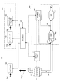
- FIG. 1 is a configuration diagram of a main part of the vehicle according to the present embodiment.
- the vehicle 1 of the present embodiment is, for example, a truck or the like, and is equipped with a diesel engine 10.
- the present disclosure is applicable not only to a vehicle equipped with a diesel engine but also to a vehicle equipped with a gasoline engine.
- Vehicle 1 has an exhaust gas purification device 100.
- the exhaust purification device 100 purifies the exhaust gas by occluding NOx in the exhaust gas of the engine 10.
- the engine 10 has, for example, a combustion chamber and a fuel injection device that injects fuel in the combustion chamber. Fuel injection in the engine 10 is controlled by the engine ECU (Electronic Control Unit) 11. The engine 10 burns and expands a mixture of fuel and air in the combustion chamber to generate torque TQ0. The engine 10 is connected to an intake pipe 20 that introduces air into the combustion chamber and an exhaust pipe 30 that discharges the exhaust gas after combustion discharged from the combustion chamber to the outside of the vehicle.
- ECU Electronic Control Unit
- the exhaust gas purification device 100 includes an LNT (Lean NOx Trap) 101, a DPF (Diesel Particulate Filter) 102, an SCR (Selective Catalytic Reduction) 103, and a purification device ECU 110. Further, in practice, the exhaust gas purification device 100 also has other configurations such as a urea water injection device, but these configurations are omitted in FIG.
- LNT101 occludes NOx in the exhaust gas when the air-fuel ratio of the exhaust gas is lean. Then, in a state where the air-fuel ratio of the exhaust gas is rich, the LNT 101 reacts the occluded NOx with CO or HC in the exhaust gas, reduces it to a harmless gas such as nitrogen, and releases it.
- DPF102 collects particulate matter contained in the exhaust gas.
- the SCR103 adsorbs hydrolyzed ammonia from urea water supplied from a urea water injection device (not shown), and selectively reduces and purifies NOx from the exhaust gas by the adsorbed ammonia.
- the purification device ECU 110 controls the operation of the exhaust gas purification device 100. Further, the ECU 110 acquires sensor information from the lambda sensor 121 provided on the upstream side of the LNT 101, the lambda sensor 122 provided on the downstream side of the LNT 101, and other sensors (not shown), and exhausts the gas based on the sensor information. The state of the exhaust gas flowing through the pipe 30, the state of the LNT 101, the state of the DPF 102, the state of the SCR 103, and the like are detected.
- the purification device ECU 110 determines the timing of LNT regeneration based on the information of the NOx storage state of the LNT 101, and sends the LNT regeneration mode signal to the engine ECU 11.
- the engine ECU 11 performs rich control for increasing the fuel injection amount in order to realize LNT regeneration.
- the vehicle 1 has a main ECU 130 that controls the entire vehicle.
- the main ECU 130 controls the engine ECU 11 and the purification device ECU 110 by communicating with the engine ECU 11 and acquires information from them.
- the accelerator signal S1 is input to the main ECU 130.
- the main ECU 130 and the engine ECU 11 control the fuel injection amount of the engine 10 according to the accelerator depression amount of the driver indicated by the accelerator signal S1.
- the main ECU 130 controls to distribute the torque TQ0 generated by the engine 10 to the traveling drive system 140 of the vehicle 1 and the other loads 150.
- the other load 150 includes an alternator 151, an exhaust brake 152, and the like.
- the main ECU 130 controls the amount of power generated by the alternator 151 according to the determined distribution torque TQ2 to the alternator 151.
- the main ECU 130 controls the opening and closing of the throttle of the exhaust brake 152 according to the determined distribution torque TQ3 to the exhaust brake 152.
- the torque may be distributed to the motor generator by including the motor generator in the other load 150.
- the engine ECU 11, the purification device ECU 110, and the main ECU 130 are configured to include, for example, a CPU (Central Processing Unit), a ROM (Read Only Memory), a RAM (Random Access Memory), an input port, an output port, and the like. ..
- the functions of the ECUs 11, 110, and 130 are realized, for example, by the CPU referring to a control program and various data stored in a ROM, RAM, or the like.
- the function is not limited to processing by software, but can also be realized by a dedicated hardware circuit.
- FIG. 2 is a waveform diagram showing the detection results (air-fuel ratios ⁇ 1 and ⁇ 2) of the lambda sensors 121 and 122 during LNT reproduction.
- the accelerator signal S1 indicating that the accelerator pedal is suddenly released is input while the engine 10 is richly controlled for LNT regeneration, the control for reducing the fuel injection amount of the engine 10 is performed. ..
- the oxygen concentration introduced into the LNT 101 sharply increases despite the rich control section (during the regeneration of the LNT 101).
- the fuel injection amount of the engine 10 is maintained even when the accelerator signal S1 indicating that the accelerator pedal has been suddenly returned is input. This control is performed in cooperation with the main ECU 130 and the engine ECU 11.
- the excess generated torque is distributed to the load 150 other than the traveling drive system 140. This control is performed by the main ECU 130.
- the main ECU 130 calculates the surplus generated torque caused by maintaining the fuel injection amount, and operates the load 150 so that the surplus generated torque is consumed.
- FIG. 3 is a waveform diagram provided for explaining the operation of the present embodiment.
- the excess torque generated by maintaining the fuel injection amount even though the accelerator is released is during the period when the accelerator is released (that is, the period of t2-t3) as shown in FIG. 3E.
- TQ2 and TQ3 of the alternator 151 and the exhaust brake 152 which are loads 150 other than the traveling drive system 140.
- an operation signal (accelerator signal S1) indicating that the torque of the traveling drive system 140 is reduced is generated.
- the surplus generated torque of the engine 10 is distributed to the load 150 of the traveling drive system 140 while maintaining the fuel injection amount of the engine 10, so that the engine 10 is richly controlled in order to regenerate the LNT 101. Even if there is a request to reduce the torque of the engine 10 during the operation, it is possible to prevent interruption of LNT reproduction, decrease in efficiency, and decrease in diagnostic accuracy of LNT purification rate.
- the foot brake is operated to consume the surplus torque.
- Excess torque can be effectively used.
- the surplus torque can be effectively utilized as compared with the case where the foot brake is operated to consume the surplus torque, for example.
- the operation signal is the accelerator signal S1 and the first load required to reduce the torque is the traveling drive system 140 has been described, but the present invention is not limited to this, and the operation is not limited to this.
- the signal and the first load may be an operation signal for which it is necessary to reduce the fuel injection amount during rich control for performing LNT regeneration, and a load to which torque corresponding to the operation signal is supplied.
- the present invention is suitable for a vehicle equipped with an LNT reproduction function.
Landscapes
- Engineering & Computer Science (AREA)
- Chemical & Material Sciences (AREA)
- Chemical Kinetics & Catalysis (AREA)
- Combustion & Propulsion (AREA)
- General Engineering & Computer Science (AREA)
- Mechanical Engineering (AREA)
- Health & Medical Sciences (AREA)
- Toxicology (AREA)
- Biomedical Technology (AREA)
- Oil, Petroleum & Natural Gas (AREA)
- General Chemical & Material Sciences (AREA)
- Analytical Chemistry (AREA)
- Environmental & Geological Engineering (AREA)
- Exhaust Gas After Treatment (AREA)
- Combined Controls Of Internal Combustion Engines (AREA)
- Exhaust Gas Treatment By Means Of Catalyst (AREA)
- Control Of Throttle Valves Provided In The Intake System Or In The Exhaust System (AREA)
- Electrical Control Of Air Or Fuel Supplied To Internal-Combustion Engine (AREA)
Abstract
車両(1)は、エンジン(10)と、NOx吸蔵還元型触媒(101)と、NOx吸蔵還元型触媒(101)を再生するためにエンジン(10)をリッチ制御しているときに、走行駆動系(140)のトルクを下げることを示す操作信号(アクセル信号S1)が入力された場合、エンジン(10)の燃料噴射量を維持したまま、エンジン(10)の余剰発生トルクを走行駆動系(140)以外の負荷(150)に分配する、制御部(メインECU130)と、を有する。
Description
本開示は、排気浄化装置を有する車両に関する。
従来、内燃機関から排出される排気中の窒素化合物(NOx)を還元浄化する触媒として、NOx吸蔵還元型触媒(Lean NOx Trap:以下「LNT」と称する)が知られている。LNTは、排気がリーン雰囲気のときに排気中に含まれるNOxを吸蔵すると共に、排気がリッチ雰囲気のときに排気中に含まれる炭化水素で吸蔵していたNOxを還元浄化により無害化して放出する。このため、触媒のNOx吸蔵量が所定量に達したなどの所定条件が成立した場合には、NOx吸蔵能力を回復させるべく、排気をリッチ状態にする所謂LNT再生(「NOxパージ」、「リッチスパイク」とも呼ばれている)を定期的に行う必要がある(例えば、特許文献1,2参照)。
ところで、上述のLNT再生中は、エンジンがリッチ制御され、排気がリッチ状態に保たれる。しかしながら、LNT再生中に、ドライバーによってアクセルを戻すなどの操作が行われると、燃料噴射量が減少し、リッチ状態がリーン方向に遷移する。これにより、LNT再生が中断されたり、もしも中断されなかったとしてもLNT再生効率が低下したりする。よって、別のタイミングで新たにLNT再生を行うことが必要となる。この結果、LNT再生の頻度が増加するといった不都合が生じる。
また、LNT再生中にドライバーの操作により燃料噴射量が減少すると、ラムダセンサーによる安定したλ検出が困難になり、LNT浄化率の診断精度も低下する問題がある。
本開示の目的は、LNTを再生するためにエンジンをリッチ制御しているときに、エンジンのトルクを下げる要求があった場合でも、LNT再生の中断や効率低下、LNT浄化率の診断精度の低下を防止できる、排気浄化装置を有する車両を提供することである。
本開示の一つの態様は、
排気浄化装置を有する車両であって、
エンジンと、
前記排気浄化装置に設けられたNOx吸蔵還元型触媒と、
前記NOx吸蔵還元型触媒を再生するために前記エンジンをリッチ制御しているときに、第1の負荷のトルクを下げることを示す操作信号が入力された場合、前記エンジンの燃料噴射量を維持したまま、前記エンジンの余剰発生トルクを前記第1の負荷以外の負荷に分配する、制御部と、
を具備する。
排気浄化装置を有する車両であって、
エンジンと、
前記排気浄化装置に設けられたNOx吸蔵還元型触媒と、
前記NOx吸蔵還元型触媒を再生するために前記エンジンをリッチ制御しているときに、第1の負荷のトルクを下げることを示す操作信号が入力された場合、前記エンジンの燃料噴射量を維持したまま、前記エンジンの余剰発生トルクを前記第1の負荷以外の負荷に分配する、制御部と、
を具備する。
本開示によれば、LNTを再生するためにエンジンをリッチ制御しているときに、エンジンのトルクを下げる要求があった場合でも、LNT再生の中断や効率低下、LNT浄化率の診断精度の低下を防止できる。
以下、図面を参照しながら、本開示の実施の形態を詳細に説明する。
図1は、本実施の形態の車両の要部構成図である。
本実施の形態の車両1は、例えばトラック等であり、ディーゼルエンジン10が搭載されている。ただし、本開示は、ディーゼルエンジンがされた車両に限らず、ガソリンエンジンが搭載された車両にも適用可能である。
車両1は、排気浄化装置100を有する。排気浄化装置100は、エンジン10の排気ガス中のNOxを吸蔵することで排気ガスを浄化する。
エンジン10は、例えば、燃焼室、燃焼室内で燃料を噴射する燃料噴射装置を有する。エンジン10での燃料噴射は、エンジンECU(Electronic Control Unit)11によって制御される。エンジン10は、燃焼室内で、燃料と空気の混合気を燃焼及び膨張させて、トルクTQ0を発生する。エンジン10には、燃焼室内に空気を導入する吸気管20と、燃焼室から排出される燃焼後の排気ガスを、車両の外部に排出する排気管30と、が接続されている。
排気浄化装置100は、LNT(Lean NOx Trap)101、DPF(Diesel Particulate Filter)102、SCR(Selective Catalytic Reduction)103及び浄化装置ECU110を有する。また、実際上、排気浄化装置100は、尿素水噴射装置などの他の構成も有するが、図1ではこれらの構成は省略されている。
LNT101は、排気ガスの空燃比がリーンな状態においては、排気ガス中のNOxを吸蔵する。そして、LNT101は、排気ガスの空燃比がリッチな状態において、当該吸蔵したNOxを排気ガス中のCO又はHC等と反応させて、窒素等の無害なガスに還元して放出する。
LNT101は、飽和状態に近づくとNOxを吸蔵し得る効率が低下する。そのため、LNT101のNOxの吸蔵状態は、浄化装置ECU110によって監視されており、定期的に、LNT101の再生(「NOxパージ」、「リッチスパイク」とも呼ばれている)が実行される。この再生は、エンジンECU11によってエンジン10の燃料噴射量が多くされるのに伴い排気ガスがリッチ状態とされ、これにより吸蔵状態のNOxが還元されることで行われる。
DPF102は、排気に含まれる粒子状物質を捕集する。
SCR103は、尿素水噴射装置(図示せず)から供給される尿素水が加水分解したアンモニアを吸着すると共に、当該吸着したアンモニアによって排気ガス中からNOxを選択的に還元浄化する。
浄化装置ECU110は、排気浄化装置100の動作を制御する。また、ECU110は、LNT101の上流側に設けられたラムダセンサー121、LNT101の下流側に設けられたラムダセンサー122や、図示しない他のセンサーからセンサー情報を取得し、当該センサー情報に基づいて、排気管30を通流する排気ガスの状態、LNT101の状態、DPF102の状態、及びSCR103の状態等を検出する。
また、浄化装置ECU110は、LNT101のNOxの吸蔵状態の情報に基づいてLNT再生のタイミングを決定し、LNT再生モード信号をエンジンECU11に送る。エンジンECU11は、LNT再生モード信号を入力すると、LNT再生を実現するために燃料噴射量を多くするリッチ制御を行う。
さらに、車両1は、車両全体を制御するメインECU130を有する。メインECU130は、エンジンECU11及び浄化装置ECU110と通信することで、これらを制御し及びこれらから情報を取得する。また、メインECU130には、アクセル信号S1が入力される。メインECU130及びエンジンECU11は、アクセル信号S1によって示されるドライバーのアクセル踏込量に応じて、エンジン10の燃料噴射量を制御する。
また、メインECU130は、エンジン10によって発生されたトルクTQ0を、車両1の走行駆動系140や、それ以外の負荷150に分配する制御を行う。それ以外の負荷150には、オルタネーター151やエキゾーストブレーキ152などが含まれる。メインECU130は、決定したオルタネーター151への分配トルクTQ2に応じて、オルタネーター151での発電量を制御する。メインECU130は、決定したエキゾーストブレーキ152への分配トルクTQ3に応じて、エキゾーストブレーキ152のスロットルの開閉を制御する。車両1がハイブリッド車の場合には、それ以外の負荷150にモーター発電機を含め、モーター発電機にトルクを分配してもよい。
因みに、エンジンECU11、浄化装置ECU110及びメインECU130は、例えば、CPU(Central Processing Unit)、ROM(Read Only Memory)、RAM(Random Access Memory)、入力ポート、及び出力ポート等を含んで構成されている。ECU11、110、130各機能は、例えば、CPUがROM、RAM等に記憶された制御プログラムや各種データを参照することによって実現される。但し、当該機能は、ソフトウェアによる処理に限られず、専用のハードウェア回路によっても実現できることは勿論である。
図2は、LNT再生時におけるラムダセンサー121、122の検出結果(空燃比λ1、λ2)を示す波形図である。一般に、LNT再生を行うためにエンジン10をリッチ制御しているときに、アクセルペダルを急激に戻したことを示すアクセル信号S1が入力されると、エンジン10の燃料噴射量を減らす制御がなされる。この結果、ラムダセンサー121の検出結果λ1から分かるように、リッチ制御区間(LNT101の再生中)であるにもかかわらず、LNT101に導入される酸素濃度が急激に上昇する。その結果、LNT再生が中断されたり、LNT再生効率が低下したりする問題が生じる。
そこで、本実施の形態では、アクセルペダルを急激に戻したことを示すアクセル信号S1が入力された場合でも、エンジン10の燃料噴射量を維持する。この制御は、メインECU130とエンジンECU11が協働して行う。
しかし、このようにすると、アクセルペダルが戻されているにもかかわらず、エンジン10では余剰なトルクが発生してしまう。そこで、本実施の形態では、この余剰発生トルクを走行駆動系140以外の負荷150に分配するようになっている。この制御は、メインECU130により行う。
具体的には、メインECU130は、燃料噴射量を維持したままとすることに起因する余剰発生トルクを計算し、この余剰発生トルクが消費されるように負荷150を作動させる。
これにより、ドライバーによるアクセルペダルの操作に準じた走行を維持させつつ、図2の点線で示したように、リッチ制御区間(LNT101の再生中)においてLNT101に導入される酸素濃度の上昇を抑制でき、LNT再生の中断や、LNT再生効率の低下を防止できる。
図3は、本実施の形態の動作の説明に供する波形図である。
図3Aに示したように、時点t1において、浄化装置ECU110からエンジンECU11にLNT再生モード信号が送られると、図3Bに示したように、エンジン10の燃料噴射量が急激に増加される。この結果、図3Dに示したように、LNT101に導入される排気ガスの空燃比λ1は急激に減少し、LNT再生が行われる。
ここで、時点t2において、アクセルの踏込量が急激に小さくなると(図3C)、従来であれば、図3Bの燃料噴射量も図3Bの一点鎖線で示されるように少なくされ、それに応じて、図3Dの一点鎖線で示されているようにLNT101に導入される排気ガスの空燃比λ1も急激に大きくなる。
これに対して、本実施の形態においては、アクセルの踏込量が大きく戻されても(図3C)、図3Bの燃料噴射量は実線で示されるように維持されたままとされ、よって、図3Dの実線で示されているようにLNT101に導入される排気ガスの空燃比λ1も低い値で維持される。この結果、LNT再生が良好な状態で維持される。
ここで、アクセルが戻されたにもかかわらず、燃料噴射量を維持したことにより発生する余剰トルクは、図3Eに示したように、アクセルが戻されている間(つまりt2-t3の期間)は、走行駆動系140以外の負荷150であるオルタネーター151及びエキゾーストブレーキ152の作動トルクTQ2、TQ3として分配して消費される。この結果、アクセルが戻されている間(つまりt2-t3の期間)に走行駆動系140に供給されるトルクTQ1は、アクセル操作が反映されたものとなる。つまり、エンジンでの発生トルクTQ0=TQ1+TQ2+TQ3とされる。
以上説明したように、本実施の形態によれば、LNT101を再生するためにエンジン10をリッチ制御しているときに、走行駆動系140のトルクを下げることを示す操作信号(アクセル信号S1)が入力された場合、エンジン10の燃料噴射量を維持したまま、エンジン10の余剰発生トルクを走行駆動系140の負荷150に分配するようにしたことにより、LNT101を再生するためにエンジン10をリッチ制御しているときに、エンジン10のトルクを下げる要求があった場合でも、LNT再生の中断や効率低下、LNT浄化率の診断精度の低下を防止できるようになる。
また、燃料噴射量を維持することにより発生する余剰トルクを、オルタネーター151などの車両の発電系に分配したことにより、例えばフットブレーキを作動させて余剰トルク分を消費させる場合などと比較して、余剰トルクを有効活用できる。同様に、余剰トルクを、エキゾーストブレーキ152に分配したことにより、例えばフットブレーキを作動させて余剰トルク分を消費させる場合などと比較して、余剰トルクを有効活用できる。
上述の実施の形態は、本発明を実施するにあたっての具体化の一例を示したものに過ぎず、これらによって本発明の技術的範囲が限定的に解釈されてはならないものである。すなわち、本発明はその要旨、またはその主要な特徴から逸脱することなく、様々な形で実施することができる。
上述の実施の形態では、操作信号がアクセル信号S1であり、トルクを下げることが要求される第1の負荷が走行駆動系140である場合について述べたが、本発明はこれに限らず、操作信号及び第1の負荷は、LNT再生を行うためのリッチ制御中に燃料噴射量を減らす必要がある操作信号、及び、その操作信号に応じたトルクが供給される負荷であればよい。
本出願は、2019年3月18日出願の特願2019-049595号に基づく優先権を主張する。当該出願明細書および図面に記載された内容は、すべて本願明細書に援用される。
本発明は、LNT再生機能が搭載された車両に好適である。
1 車両
10 エンジン
11 エンジンECU(Electronic Control Unit)
20 吸気管
30 排気管
100 排気浄化装置
101 LNT(Lean NOx Trap)
102 DPF(Diesel Particulate Filter)
103 SCR(Selective Catalytic Reduction)
110 浄化装置ECU
121、122 ラムダセンサー
130 メインECU
140 走行駆動系
150 負荷
151 オルタネーター
152 エキゾーストブレーキ
S1 アクセル信号
TQ0~TQ3 トルク
10 エンジン
11 エンジンECU(Electronic Control Unit)
20 吸気管
30 排気管
100 排気浄化装置
101 LNT(Lean NOx Trap)
102 DPF(Diesel Particulate Filter)
103 SCR(Selective Catalytic Reduction)
110 浄化装置ECU
121、122 ラムダセンサー
130 メインECU
140 走行駆動系
150 負荷
151 オルタネーター
152 エキゾーストブレーキ
S1 アクセル信号
TQ0~TQ3 トルク
Claims (4)
- 排気浄化装置を有する車両であって、
エンジンと、
前記排気浄化装置に設けられたNOx吸蔵還元型触媒と、
前記NOx吸蔵還元型触媒を再生するために前記エンジンをリッチ制御しているときに、第1の負荷のトルクを下げることを示す操作信号が入力された場合、前記エンジンの燃料噴射量を維持したまま、前記エンジンの余剰発生トルクを前記第1の負荷以外の負荷に分配する、制御部と、
を具備する車両。 - 前記制御部は、前記操作信号による前記トルクの減少量を算出し、当該減少量に相当する前記余剰発生トルクを前記第1の負荷以外の負荷に分配する、
請求項1に記載の車両。 - 前記第1の負荷は、車両の走行駆動系であり、
前記第1の負荷以外の負荷は、車両の発電系を含む、
請求項1に記載の車両。 - 前記第1の負荷は、車両の走行駆動系であり、
前記第1の負荷以外の負荷は、エキゾーストブレーキを含み、前記余剰発生トルクに応じて前記エキゾーストブレーキのスロットルの開閉を制御する、
請求項2に記載の車両。
Priority Applications (2)
| Application Number | Priority Date | Filing Date | Title |
|---|---|---|---|
| PH1/2021/552214A PH12021552214A1 (en) | 2019-03-18 | 2020-03-16 | Vehicle with exhaust gas purifying device |
| CN202080022228.4A CN113597509A (zh) | 2019-03-18 | 2020-03-16 | 具有废气净化装置的车辆 |
Applications Claiming Priority (2)
| Application Number | Priority Date | Filing Date | Title |
|---|---|---|---|
| JP2019049595A JP7183886B2 (ja) | 2019-03-18 | 2019-03-18 | 排気浄化装置を有する車両 |
| JP2019-049595 | 2019-03-18 |
Publications (1)
| Publication Number | Publication Date |
|---|---|
| WO2020189634A1 true WO2020189634A1 (ja) | 2020-09-24 |
Family
ID=72520903
Family Applications (1)
| Application Number | Title | Priority Date | Filing Date |
|---|---|---|---|
| PCT/JP2020/011509 Ceased WO2020189634A1 (ja) | 2019-03-18 | 2020-03-16 | 排気浄化装置を有する車両 |
Country Status (4)
| Country | Link |
|---|---|
| JP (1) | JP7183886B2 (ja) |
| CN (1) | CN113597509A (ja) |
| PH (1) | PH12021552214A1 (ja) |
| WO (1) | WO2020189634A1 (ja) |
Citations (4)
| Publication number | Priority date | Publication date | Assignee | Title |
|---|---|---|---|---|
| JP2006248519A (ja) * | 1998-03-19 | 2006-09-21 | Hitachi Ltd | ハイブリッド自動車 |
| JP2007230302A (ja) * | 2006-02-28 | 2007-09-13 | Nissan Motor Co Ltd | ディーゼルハイブリッド車両の排気浄化装置 |
| JP2007246009A (ja) * | 2006-03-17 | 2007-09-27 | Mitsubishi Fuso Truck & Bus Corp | ハイブリッド電気自動車の制御装置 |
| JP2016179740A (ja) * | 2015-03-24 | 2016-10-13 | トヨタ自動車株式会社 | ハイブリッド車両の駆動装置 |
Family Cites Families (5)
| Publication number | Priority date | Publication date | Assignee | Title |
|---|---|---|---|---|
| JP3783712B2 (ja) * | 2003-12-03 | 2006-06-07 | トヨタ自動車株式会社 | ハイブリッド車両における内燃機関の制御方法 |
| JP4973374B2 (ja) * | 2007-08-07 | 2012-07-11 | 日産自動車株式会社 | ハイブリッド原動機の制御装置 |
| JP2010090730A (ja) * | 2008-10-03 | 2010-04-22 | Toyota Motor Corp | 排気浄化触媒用の温度制御装置 |
| CN103140402A (zh) * | 2010-10-21 | 2013-06-05 | 日野自动车株式会社 | 再生控制装置、混合动力汽车、再生控制方法、以及程序 |
| JP5825282B2 (ja) * | 2013-03-26 | 2015-12-02 | トヨタ自動車株式会社 | ハイブリッド車両の制御装置 |
-
2019
- 2019-03-18 JP JP2019049595A patent/JP7183886B2/ja active Active
-
2020
- 2020-03-16 WO PCT/JP2020/011509 patent/WO2020189634A1/ja not_active Ceased
- 2020-03-16 PH PH1/2021/552214A patent/PH12021552214A1/en unknown
- 2020-03-16 CN CN202080022228.4A patent/CN113597509A/zh active Pending
Patent Citations (4)
| Publication number | Priority date | Publication date | Assignee | Title |
|---|---|---|---|---|
| JP2006248519A (ja) * | 1998-03-19 | 2006-09-21 | Hitachi Ltd | ハイブリッド自動車 |
| JP2007230302A (ja) * | 2006-02-28 | 2007-09-13 | Nissan Motor Co Ltd | ディーゼルハイブリッド車両の排気浄化装置 |
| JP2007246009A (ja) * | 2006-03-17 | 2007-09-27 | Mitsubishi Fuso Truck & Bus Corp | ハイブリッド電気自動車の制御装置 |
| JP2016179740A (ja) * | 2015-03-24 | 2016-10-13 | トヨタ自動車株式会社 | ハイブリッド車両の駆動装置 |
Also Published As
| Publication number | Publication date |
|---|---|
| JP2020153245A (ja) | 2020-09-24 |
| JP7183886B2 (ja) | 2022-12-06 |
| CN113597509A (zh) | 2021-11-02 |
| PH12021552214A1 (en) | 2022-05-30 |
Similar Documents
| Publication | Publication Date | Title |
|---|---|---|
| JP3399466B2 (ja) | 内燃機関の排気浄化装置 | |
| US9604177B2 (en) | Exhaust gas purification apparatus for an internal combustion engine | |
| CN104395573B (zh) | 内燃机的排气净化装置 | |
| US9297289B2 (en) | Exhaust gas purification apparatus for an internal combustion engine | |
| JP5686036B2 (ja) | 内燃機関の制御装置 | |
| JP3806399B2 (ja) | 内燃機関の排気浄化装置 | |
| JP4935929B2 (ja) | 内燃機関の排気浄化装置 | |
| JP6973195B2 (ja) | 排気浄化装置、車両および排気浄化制御装置 | |
| JP2018189056A (ja) | 内燃機関の排気浄化装置 | |
| KR20070049859A (ko) | 디젤 자동차의 배기가스 정화장치 및 그 재생방법 | |
| CN101316994A (zh) | 用于处理机动车排气的氮氧化物的装置 | |
| JP2016211454A (ja) | 内燃機関の制御装置 | |
| JP7183886B2 (ja) | 排気浄化装置を有する車両 | |
| JP3552603B2 (ja) | 内燃機関の排気浄化装置 | |
| US10738678B2 (en) | Correction method of NOx purifying efficiency of SDPF | |
| JP3539286B2 (ja) | 内燃機関の排気浄化装置 | |
| JP2009036153A (ja) | 内燃機関の排気浄化装置 | |
| US11193408B2 (en) | Reactivation control apparatus and method | |
| JP2020033984A (ja) | 内燃機関の排気浄化装置、及び車両 | |
| JP4635868B2 (ja) | 内燃機関の排気浄化装置 | |
| JP2019132165A (ja) | エンジンの排気浄化制御装置 | |
| KR101816424B1 (ko) | 질소산화물 정화 장치의 배출 가스 공연비 제어 방법 | |
| KR20230067717A (ko) | 배기가스 후처리 시스템 및 방법 | |
| JP2004176664A (ja) | 内燃機関の排気浄化装置 | |
| JP2007309108A (ja) | 内燃機関の排気浄化装置 |
Legal Events
| Date | Code | Title | Description |
|---|---|---|---|
| 121 | Ep: the epo has been informed by wipo that ep was designated in this application |
Ref document number: 20772570 Country of ref document: EP Kind code of ref document: A1 |
|
| NENP | Non-entry into the national phase |
Ref country code: DE |
|
| 122 | Ep: pct application non-entry in european phase |
Ref document number: 20772570 Country of ref document: EP Kind code of ref document: A1 |