WO2020189622A1 - 車両用バッテリ冷却装置 - Google Patents
車両用バッテリ冷却装置 Download PDFInfo
- Publication number
- WO2020189622A1 WO2020189622A1 PCT/JP2020/011452 JP2020011452W WO2020189622A1 WO 2020189622 A1 WO2020189622 A1 WO 2020189622A1 JP 2020011452 W JP2020011452 W JP 2020011452W WO 2020189622 A1 WO2020189622 A1 WO 2020189622A1
- Authority
- WO
- WIPO (PCT)
- Prior art keywords
- flow path
- path forming
- holes
- forming member
- fluid
- Prior art date
- Legal status (The legal status is an assumption and is not a legal conclusion. Google has not performed a legal analysis and makes no representation as to the accuracy of the status listed.)
- Ceased
Links
Images



Classifications
-
- H—ELECTRICITY
- H01—ELECTRIC ELEMENTS
- H01M—PROCESSES OR MEANS, e.g. BATTERIES, FOR THE DIRECT CONVERSION OF CHEMICAL ENERGY INTO ELECTRICAL ENERGY
- H01M10/00—Secondary cells; Manufacture thereof
- H01M10/60—Heating or cooling; Temperature control
- H01M10/61—Types of temperature control
- H01M10/613—Cooling or keeping cold
-
- H—ELECTRICITY
- H01—ELECTRIC ELEMENTS
- H01M—PROCESSES OR MEANS, e.g. BATTERIES, FOR THE DIRECT CONVERSION OF CHEMICAL ENERGY INTO ELECTRICAL ENERGY
- H01M10/00—Secondary cells; Manufacture thereof
- H01M10/60—Heating or cooling; Temperature control
- H01M10/62—Heating or cooling; Temperature control specially adapted for specific applications
- H01M10/625—Vehicles
-
- H—ELECTRICITY
- H01—ELECTRIC ELEMENTS
- H01M—PROCESSES OR MEANS, e.g. BATTERIES, FOR THE DIRECT CONVERSION OF CHEMICAL ENERGY INTO ELECTRICAL ENERGY
- H01M10/00—Secondary cells; Manufacture thereof
- H01M10/60—Heating or cooling; Temperature control
- H01M10/65—Means for temperature control structurally associated with the cells
- H01M10/655—Solid structures for heat exchange or heat conduction
- H01M10/6556—Solid parts with flow channel passages or pipes for heat exchange
-
- H—ELECTRICITY
- H01—ELECTRIC ELEMENTS
- H01M—PROCESSES OR MEANS, e.g. BATTERIES, FOR THE DIRECT CONVERSION OF CHEMICAL ENERGY INTO ELECTRICAL ENERGY
- H01M10/00—Secondary cells; Manufacture thereof
- H01M10/60—Heating or cooling; Temperature control
- H01M10/65—Means for temperature control structurally associated with the cells
- H01M10/656—Means for temperature control structurally associated with the cells characterised by the type of heat-exchange fluid
- H01M10/6567—Liquids
- H01M10/6568—Liquids characterised by flow circuits, e.g. loops, located externally to the cells or cell casings
-
- Y—GENERAL TAGGING OF NEW TECHNOLOGICAL DEVELOPMENTS; GENERAL TAGGING OF CROSS-SECTIONAL TECHNOLOGIES SPANNING OVER SEVERAL SECTIONS OF THE IPC; TECHNICAL SUBJECTS COVERED BY FORMER USPC CROSS-REFERENCE ART COLLECTIONS [XRACs] AND DIGESTS
- Y02—TECHNOLOGIES OR APPLICATIONS FOR MITIGATION OR ADAPTATION AGAINST CLIMATE CHANGE
- Y02E—REDUCTION OF GREENHOUSE GAS [GHG] EMISSIONS, RELATED TO ENERGY GENERATION, TRANSMISSION OR DISTRIBUTION
- Y02E60/00—Enabling technologies; Technologies with a potential or indirect contribution to GHG emissions mitigation
- Y02E60/10—Energy storage using batteries
Definitions
- the present invention relates to a vehicle battery cooling device that cools a battery mounted on a vehicle.
- a so-called hybrid vehicle equipped with an internal combustion engine and a motor is equipped with a battery for operating the motor.
- the battery heats up when it operates while the vehicle is running. Therefore, a vehicle battery cooling device for cooling the battery is arranged so as to thermally couple with the battery.
- a conventional technique relating to a vehicle battery cooling device there is a technique disclosed in Patent Document 1.
- the vehicle battery cooling device disclosed in Patent Document 1 includes a cooling member formed by superimposing two plates having irregularities formed therein.
- the cooling member having the unevenness formed serves as a flow path of the cooling medium, and the cooling medium is passed through the flow path to cool the battery by heat exchange with the cooling medium.
- a vehicle battery cooling device as shown in Patent Document 1 is, for example, brazed after stacking two plates.
- a long mileage is required. Therefore, in order to increase the storage capacity, a large number of battery cells are arranged on the vehicle body. Then, in order to cool the entire battery having a large number of battery cells, the plate constituting the vehicle battery cooling device is also increased in size. That is, the vehicle battery cooling device requires a plate member having a large cooling area. When stacking plates with a large area, the plates may be twisted or bent due to the weight of the plates. Therefore, it takes time to accurately align the positions of the plates having a large area, and the time required for manufacturing the vehicle battery cooling device becomes long.
- An object of the present invention is to provide a vehicle battery cooling device that can be easily positioned and easily assembled.
- a vehicle battery cooling device (20; 20A; 20B) provided so as to be in contact with a battery (Ba) mounted on a vehicle and cooling the battery (Ba) by a cooling medium flowing inside.
- the second surface (21c) which has a second space having a substantially U-shaped cross section and is the back surface of the first surface (21b), and the second space have a two-sided flow path (R2) of the cooling medium.
- the second flow path forming member (40x, 40y) for forming the above is provided.
- the holes (21ax, 21ay) are a plurality of holes (21ax) belonging to a first hole group formed along the surface of the plate member (21) along the X direction, and the surfaces of the plate member (21).
- the second flow path forming member (40x, 40y) belongs to the one-sided second flow path forming member (40x) communicating with the hole (21ax) belonging to the first hole group and the second hole group.
- a vehicle battery cooling device characterized by having a second flow path forming member (40y) on the other side communicating with the hole (21ay).
- the X direction and the Y direction are parallel to each other.
- the number of holes (21ax) belonging to the first hole group and the number of holes (21ay) belonging to the second hole group are equal.
- the holes (21ax) belonging to the first hole group are formed at equal intervals.
- the holes (21ay) belonging to the second hole group are formed at equal intervals.
- a fluid inflow portion (25) arranged so as to face the second space of the one-sided second flow path forming member (40x) and into which the cooling medium flows, and the other side second flow path forming member (40y).
- a fluid outflow portion (26) arranged so as to face the second space and outflow of the cooling medium.
- the first flow path forming member (30) having the shortest flow path length from the fluid inflow portion (25) is the fluid outflow portion based on the length of the two-sided flow path (R2).
- the first flow path forming member (30) having the longest flow path length from (26) and the longest flow path length from the fluid inflow section (25) is a flow path from the fluid outflow section (26).
- the fluid inflow portion (25) and the fluid outflow portion (26) are arranged so that the length is the shortest.
- the fluid inflow portion (25) and the fluid outflow portion (26) are both formed by holes formed in the plate member (21).
- the other side second flow path forming member (40y) is connected to an extension portion (50) extending so that the fluid outflow portion (26) is adjacent to the fluid inflow portion (25). Has been done.
- the one-sided second flow path forming member (40x) is connected to an extension portion (50) extending so that the fluid inflow portion (25) is adjacent to the fluid outflow portion (26). Has been done.
- the vehicle battery cooling device is formed by superimposing a first flow path forming member and a second flow path forming member, both of which are formed in a substantially U shape, on a plate member having a hole. .. By superimposing each flow path member on the plate member, each component can be easily positioned. It is possible to provide a vehicle battery cooling device that is easy to position and can be easily assembled.
- FIG. 3 is a sectional view taken along line 4-4 of FIG.
- FIG. 5 is a sectional view taken along line 5-5 of FIG. It is a figure explaining the operation of the vehicle battery cooling device shown in FIG.
- It is a top view of the vehicle battery cooling device according to the second embodiment.
- It is a top view of the vehicle battery cooling device according to the third embodiment.
- FIG. 1 shows a battery cooling system 10 for cooling a vehicle battery Ba.
- Hybrid vehicles, electric vehicles, and the like are equipped with a vehicle battery Ba for driving a motor. Since the vehicle battery Ba generates heat when it operates, it is necessary to cool it.
- the battery cooling system 10 is arranged along the lower surface of the vehicle battery Ba, and is a vehicle battery cooling device 20 (hereinafter, referred to as “cooling device 20”) that cools the vehicle battery Ba by a cooling medium flowing inside.
- a cooling medium for example, water to which an antifreeze agent is added is used.
- the battery cooling system 10 further includes a fluid cooling unit 12 for cooling the cooling medium whose temperature has risen by heat exchange with the vehicle battery Ba, and a pump 13 for circulating the cooling medium.
- a part of the refrigerant used for the air conditioner for air-conditioning the interior of the vehicle flows through the fluid cooling unit 12.
- the cooling medium heated through the cooling device 20 is cooled in the fluid cooling unit 12 by the refrigerant from the air conditioner device.
- the cooling device 20 can be arranged along any surface such as the upper surface and the side surface in addition to the lower surface of the vehicle battery Ba.
- the cooling device 20 includes a plate-shaped plate member 21 in which a plurality of circular holes 21ax and 21ay are formed, and a first flow path forming member fixed to an upper surface 21b (first surface 21b) of the plate member 21.
- the inflow section 25, the fluid outflow section 26 composed of holes formed in the plate member 21 and outflowing the high-temperature cooling medium, the inflow section connecting member 27 connected to the fluid inflow section 25, and the fluid outflow section 26. It has an outflow portion connecting member 28 which is connected.
- the plate member 21 made of a metal plate has a substantially rectangular shape, and the portions 21d and 21e in which the fluid inflow portion 25 and the fluid outflow portion 26 are formed project from their respective sides. In other words, only the portions necessary for the inflow and outflow of the cooling medium are formed as protruding portions 21d and 21e so as to protrude from the substantially rectangular portions.
- the plate member 21 is covered with the first flow path forming member 30 and the second flow path forming member 40x, 40y, and has a plurality of holes 21ax, 21ay through which the cooling medium can pass.
- the plate member 21 is made of a metal material that can be brazed.
- a metal material that can be brazed.
- aluminum alloys, copper alloys, stainless alloys and the like are used.
- the plate member 21 can be formed by press forming or laser processing, including the formation of holes 21ax, 21ay, fluid inflow portion 25, and fluid outflow portion 26.
- the holes 21ax and 21ay are circular holes having the same diameter.
- the holes 21ax and 21ay can be divided into two groups, a first hole group and a second hole group.
- the hole 21ax belonging to the first hole group is formed on the line Lx extending in the X direction on the surface of the plate member 21.
- the line Lx passes through the center (center of gravity) of the holes 21ax belonging to the first hole group.
- the holes 21ax belonging to the first hole group are formed at equal intervals so that their respective intervals are t1.
- the hole 21ay belonging to the second hole group is formed on the line Ly extending in the Y direction on the surface of the plate member 21.
- the line Ly passes through the center (center of gravity) of the holes 21ay belonging to the second hole group.
- the holes 21ay belonging to the second hole group are formed at equal intervals so that the intervals between them are t2.
- the line Lx extending in the X direction and the line Ly extending in the Y direction extend parallel to each other and parallel to one side of the rectangular plate member 21.
- the shape of the holes 21ax and 21ay may be a shape other than a circular shape, for example, an elongated hole shape or the like. Further, the shape of each hole may be different. Even in this case, it is preferable that the holes 21ax and 21ay are formed so that the lines Lx and Ly pass through the center (center of gravity) of the holes 21ax and 21ay.
- first flow path forming members 30 are provided in parallel with each other in a direction orthogonal to one side of the plate member 21.
- the same member is used for each of the first flow path forming members 30, and they are fixed to the plate member 21 by, for example, brazing.
- the first flow path forming member 30 is formed of, for example, an aluminum alloy, a copper alloy, a stainless alloy, or the like. In order to ensure brazing property, a metal of the same series as the plate member 21 is selected as the material of the first flow path forming member 30.
- the first flow path forming member 30 covers one hole 21ax belonging to the first hole group and one hole 21ay belonging to the second hole group.
- Each of the first flow path forming members 30 has a first space having a substantially U-shaped cross section, and the upper surface 21b of the plate member 21 and the first space form a one-sided flow path R1 of the cooling medium.
- first flow path forming member 30 may be arranged diagonally instead of in a direction orthogonal to the plate member 21 depending on the position where the holes 21ax and 21ay are formed (not shown).
- Each hole of the hole 21ax belonging to the first hole group and each hole of the hole 21ay belonging to the second hole group are arranged so as to cover the same number (for example, one by one) while ensuring airtightness. It suffices if it is done.
- the second flow path forming members 40x and 40y have a second space having a substantially U-shaped cross section, and the second surface 21c and the second space form a two-sided flow path R2 of the cooling medium.
- the second flow path forming members 40x and 40y are fixed to the plate member 21 by, for example, brazing.
- the second flow path forming members 40x and 40y are formed of, for example, an aluminum alloy, a copper alloy, a stainless alloy, or the like. In order to ensure brazing property, a metal of the same series as the plate member 21 is selected as the material of the second flow path forming members 40x and 40y.
- Two second flow path forming members 40x and 40y are provided parallel to one side of the plate member 21 and parallel to each other.
- the second flow path forming members 40x and 40y may be arranged diagonally instead of in a direction orthogonal to the plate member 21 depending on the position where the holes 21ax and 21ay are formed (not shown). ..
- Each hole of the hole 21ax belonging to the first hole group may be arranged so as to cover each hole while ensuring airtightness.
- each hole of the hole 21ay belonging to the second hole group may be arranged so as to cover each hole while ensuring airtightness.
- the second flow path forming members 40x and 40y are the one-sided second flow path forming member 40x communicating with the hole 21ax belonging to the first hole group and the fluid inflow portion 25, and the hole 21ay and the fluid belonging to the second hole group. It has a second flow path forming member 40y on the other side that communicates with the outflow portion 26.
- the one-side second flow path forming member 40x covers all of the holes 21ax belonging to the first hole group and the fluid inflow portion 25, and the other side second flow path forming member 40y belongs to the second hole group. It covers all of the holes 21ay and the fluid outflow portion 26.
- the fluid inflow portion 25 is formed in the protruding portion 21d by a round hole and faces the second space of the second flow path forming member 40x on one side.
- the fluid inflow portion 25 is formed on the line Lx extending in the X direction. In plan view, the line Lx passes through the center of the fluid inflow portion 25.
- the fluid outflow portion 26 is formed in the protruding portion 21e by a round hole and faces the second space of the second flow path forming member 40y on the other side.
- the fluid outflow portion 26 is formed on a line Ly extending in the Y direction. In plan view, the line Ly passes through the center of the fluid outflow portion 26.
- the cooling medium cooled by the fluid cooling unit 12 is sent to the cooling device 20.
- FIG. 6 shows a cooling device 20 in which the inflow portion connecting member 27 (see FIG. 3) and the outflow portion connecting member 28 (see FIG. 3) are removed for convenience of explanation.
- the cooling medium flows from the fluid inflow portion 25 into the two-sided flow path R2 formed by the one-side second flow path forming member 40x.
- a part of the cooling medium flowing through the two-sided flow path R2 branches at the branch point P1, and the first flow path forming member 30-1 (-1 is a subscript for identifying the first flow path forming member 30). The same applies hereinafter in FIG. 6), and the flow flows through the one-sided flow path R1.
- the cooling medium is branched into the first flow path forming members 30-2 to 30-4, and flows through the one-sided flow path R1 formed by each.
- a high-temperature battery Ba (see FIG. 1) is placed on the upper surfaces of the first flow path forming members 30-1 to 30-4 so as to be thermally coupled.
- the cooling medium passing through the one-sided flow path R1 cools the battery Ba via the first flow path forming members 30-1 to 30-4. That is, heat exchange is performed.
- the cooling medium heated by the heat of the battery Ba flows into the two-sided flow path R2 formed by the other side second flow path forming member 40y, and joins at the merging portion P2.
- the combined cooling medium flows out from the fluid outflow portion 26.
- the cooling medium that has passed through the fluid outflow section 26 and has flowed out of the outflow section connecting member 28 is sent to the fluid cooling section 12, cooled, and sent to the cooling device 20 again.
- the first flow path forming member 30-1 having the shortest flow path length from the fluid inflow section 25 has the longest flow path length from the fluid outflow section 26.
- the first flow path forming member 30-4 having the longest flow path length from the fluid inflow section 25 has the shortest flow path length from the fluid outflow section 26.
- the positions of the fluid inflow section 25 and the fluid outflow section 26 are such that the first flow path forming member 30-1 having the shortest flow path length from the fluid inflow section 25 has a flow path length to the fluid outflow section 26.
- the first flow path forming member 30-4, which is the longest and has the longest flow path length from the fluid inflow section 25, is set so that the flow path length to the fluid outflow section 26 is the shortest.
- the flow path length of the cooling medium that flows in from the fluid inflow section 25 and flows out from the fluid outflow section 26 is the same regardless of whether it passes through any of the first flow path forming members 30-1 to 30-4.
- the cooling device 20 described above has the following effects.
- the cooling device 20 is formed by superimposing a first flow path forming member 30 and a second flow path forming member 40x, 40y, both of which are formed in a substantially U shape, on a plate member 21 having holes 21ax and 21ay. ..
- a first flow path forming member 30 and a second flow path forming member 40x, 40y both of which are formed in a substantially U shape, on a plate member 21 having holes 21ax and 21ay. ..
- the flow path forming members 30, 40x, and 40y By superimposing the flow path forming members 30, 40x, and 40y on the plate member 21, the positioning of each component can be easily performed. It is possible to provide a vehicle battery cooling device that is easy to position and can be easily assembled.
- the first flow path forming member 30 communicates with either one of the holes 21ax belonging to the first hole group and one of the holes 21ay belonging to the second hole group.
- the second flow path forming members 40x and 40y are the one side second flow path forming member 40x communicating with the hole 21ax belonging to the first hole group and the other side communicating with the hole 21ay belonging to the second hole group. It has a second flow path forming member 40y.
- the X direction and the Y direction are parallel, and the number of holes 21ax belonging to the first hole group and the number of holes 21ay belonging to the second hole group are equal. Further, the holes 21ax belonging to the first hole group are formed at equal intervals (t1), and the holes 21ay belonging to the second hole group are formed at equal intervals (t2), respectively.
- the plurality of first flow path forming members 30 can each be composed of the same parts, and the one side second flow path forming members 40x and 40y and the other side second flow path forming members 40x and 40y are also the same parts. Can be configured with. It is possible to improve the efficiency of the assembly work by standardizing the parts and suppressing the assembly of the flow path forming members 30, 40x and 40y to the wrong positions.
- the first flow path forming member 30-1 having the shortest flow path length from the fluid inflow section 25 has the longest flow path length from the fluid outflow section 26 and the longest flow path length from the fluid inflow section 25.
- the fluid inflow section 25 and the fluid outflow section 26 are arranged so that the flow path length from the fluid outflow section 26 is the shortest.
- the cooling medium flowing in from the fluid inflow section 25 passes through the one-side second flow path forming member 40x, the first flow path forming member 30, and the other side second flow path forming member 40y, and flows out from the fluid outflow section 26.
- Both the fluid inflow portion 25 and the fluid outflow portion 26 are composed of holes formed in the plate member 21.
- the fluid inflow portion 25 and the fluid outflow portion 26 can be formed by press working or laser working together with the holes 21ax and 21ay forming a part of the flow path. The number of steps required for processing can be reduced, and the vehicle battery cooling device 20 can be made inexpensive.
- the cooling device 20A according to the second embodiment is further provided with an extension portion 50.
- Other basic configurations are the same as those of the cooling device according to the first embodiment.
- reference numerals are used and detailed description thereof will be omitted.
- the extension portion 50 extends in a direction orthogonal to the first member 51 which is connected to the other side second flow path forming member 40y and extends parallel to the first flow path forming member 30 and the end portion of the first member 51. It has a second member 52 and.
- the outflow portion connecting member 28 faces the end of the second member 52.
- the outflow portion connecting member 28 is provided adjacent to the inflow portion connecting member 27. That is, the fluid outflow portion is formed at a position adjacent to the fluid inflow portion.
- the vehicle battery cooling device 20A described above also exerts the predetermined effect of the present invention.
- an extension portion 50 that extends the fluid outflow portion 26 so as to be adjacent to the fluid inflow portion 25 is connected to the second flow path forming member 40y on the other side.
- the fluid inflow section 25 and the fluid outflow section 26 can be brought close to each other, and for example, the connection structure of the pipe for connecting to the fluid cooling section 12 (see FIG. 1) can be made compact.
- the extension portion 50 is extended from the fluid inflow portion, and the fluid inflow portion is arranged in the vicinity of the fluid outflow portion. That is, the extension portion 50 that extends the fluid inflow portion so as to be adjacent to the fluid outflow portion may be connected to the second flow path forming member on one side. Also in this case, the connection structure of the piping of the vehicle battery cooling device 20A can be made compact.
- the fluid introduction portion (inflow portion connecting member 27) and the fluid outflow portion (outflow portion connecting member 28) are formed on the same side of the plate member 21.
- Other basic configurations are common to the cooling devices 20 and 20A according to the first and / or second embodiment.
- the reference numerals are used and detailed description thereof will be omitted.
- the flow path length differs depending on the first flow path forming member 30 passing through.
- a large amount of fluid flows through the first flow path forming member 30 (the first flow path forming member 30 at the bottom of the drawing), which has the shortest flow path length.
- a part of the battery Ba becomes particularly hot, a larger amount of fluid can flow by shortening the flow path length of the first flow path forming member 30 that abuts on such a portion. Can be done. As a result, the battery Ba can be cooled efficiently.
- the opening area of the holes 21ax and 21ay in the portion where the flow path length becomes long may be formed so as to be relatively larger than the opening area of the holes 21ax and 21ay in the portion where the flow path length becomes short.
- the cooling device 20B described above also exerts the predetermined effect of the present invention.
- a fluid inflow portion (inflow portion connecting member 27) and a fluid outflow portion (outflow portion connecting member 28) are formed on the same side of a substantially rectangular plate-shaped plate member 21. Therefore, the fluid inflow portion and the fluid outflow portion can be formed in close proximity to each other without providing the extension portion 50 (see FIG. 7).
- the vehicle battery cooling device of the present invention is suitable for mounting on a hybrid vehicle.
- Vehicle battery cooling device 21 Plate member, 21ax ... Hole belonging to the first hole group, 21ay ... Hole belonging to the second hole group, 21b ... Upper surface (first surface), 21c ... Lower surface (Second side) 25 ... Fluid inflow part 26 ... Fluid outflow part 30 ... First flow path forming member 40x ... One side second flow path forming member, 40y ... Other side second flow path forming member Lx ... Line extending in the X direction, Ly ... Y Line extending in the direction R1 ... 1-sided flow path R2 ... 2-sided flow path Ba ... Vehicle battery
Landscapes
- Engineering & Computer Science (AREA)
- Manufacturing & Machinery (AREA)
- Chemical & Material Sciences (AREA)
- Chemical Kinetics & Catalysis (AREA)
- Electrochemistry (AREA)
- General Chemical & Material Sciences (AREA)
- Secondary Cells (AREA)
- Cooling, Air Intake And Gas Exhaust, And Fuel Tank Arrangements In Propulsion Units (AREA)
- Battery Mounting, Suspending (AREA)
Abstract
【課題】位置決めが簡単で容易に組み立てることのできる車両用バッテリ冷却装置を提供すること。 【解決手段】車両用バッテリ冷却装置(20;20A;20B)は、複数の穴(21ax、21ay)が形成された板状のプレート部材(21)と、略U字状を呈し1面側流路(R1)と穴(21ax、21ay)とが連通するように第1面(21b)に配置された第1流路形成部材(30)と、略U字状を呈し2面側流路(R2)と穴(21ax、21ay)とが連通するように第2面(21c)に配置された第2流路形成部材(40x、40y)と、を有する。
Description
本発明は、車両に搭載されたバッテリを冷却する車両用バッテリ冷却装置に関する。
内燃機関とモータとが搭載されている、いわゆるハイブリッド車両には、モータを作動させるためのバッテリが搭載されている。車両の走行中に作動することにより、バッテリは、発熱する。このため、バッテリを冷却するための車両用バッテリ冷却装置がバッテリと熱的に結合するよう配置される。車両用バッテリ冷却装置に関する従来技術として、特許文献1に開示される技術がある。
特許文献1に開示された車両用バッテリ冷却装置は、凹凸が形成された2枚のプレートを重ね合わせて構成された冷却部材を備える。凹凸が形成された冷却部材が冷却媒体の流路とされ、流路に冷却媒体を流し、冷却媒体との熱交換によってバッテリを冷却する。
特許文献1に示されるような車両用バッテリ冷却装置は、例えば、2枚の板を重ね合わせた上でろう付けされる。ここで、ハイブリッド車両や電動車両においては、長い走行距離が求められている。このため蓄電容量を増やすために、車体には多数のバッテリセルが配置される。そして、多数のバッテリセルを有するバッテリの全体を冷却するために、車両用バッテリ冷却装置を構成する板も大型化する。すなわち、車両用バッテリ冷却装置には、冷却面積の大きな板部材が要る。大きな面積の板を重ね合わせる際には、板の自重等により板が捩れたり、撓むことがある。このため、大きな面積の板同士の位置を正確に合わせるのに時間がかかり、車両用バッテリ冷却装置の製造に必要な時間が長くなる。
本発明は、位置決めが簡単で容易に組み立てることのできる車両用バッテリ冷却装置の提供を課題とする。
以下の説明では、本発明の理解を容易にするために添付図面中の参照符号を括弧書きで付記するが、それによって本発明は図示の形態に限定されるものではない。
本発明によれば、車両に搭載されたバッテリ(Ba)に接するように設けられ、内部を流れる冷却媒体によって前記バッテリ(Ba)を冷却する車両用バッテリ冷却装置(20;20A;20B)において、
複数の穴(21ax、21ay)が形成された板状のプレート部材(21)と、
断面が略U字状の第1空間を有し、前記プレート部材(21)の第1面(21b)と前記第1空間とで前記冷却媒体の1面側流路(R1)を形成する第1流路形成部材(30)と、
断面が略U字状の第2空間を有し、前記第1面(21b)の裏面である第2面(21c)と前記第2空間とで前記冷却媒体の2面側流路(R2)を形成する第2流路形成部材(40x、40y)と、を備え、
前記穴(21ax、21ay)は、前記プレート部材(21)の面上をX方向に沿って形成された第1の穴グループに属する複数の穴(21ax)と、前記プレート部材(21)の面上をY方向に沿って形成された第2の穴グループに属する複数の穴(21ay)と、のいずれかに属し、
前記第1流路形成部材(30)は、複数配置され、前記1面側流路(R1)が前記第1の穴グループに属する穴(21ax)のいずれかと、前記第2の穴グループに属する穴(21ay)のいずれかと、を連通し、
前記第2流路形成部材(40x、40y)は、前記第1の穴グループに属する穴(21ax)に連通する一方側第2流路形成部材(40x)と、前記第2の穴グループに属する穴(21ay)に連通する他方側第2流路形成部材(40y)と、を有することを特徴とする車両用バッテリ冷却装置が提供される。
複数の穴(21ax、21ay)が形成された板状のプレート部材(21)と、
断面が略U字状の第1空間を有し、前記プレート部材(21)の第1面(21b)と前記第1空間とで前記冷却媒体の1面側流路(R1)を形成する第1流路形成部材(30)と、
断面が略U字状の第2空間を有し、前記第1面(21b)の裏面である第2面(21c)と前記第2空間とで前記冷却媒体の2面側流路(R2)を形成する第2流路形成部材(40x、40y)と、を備え、
前記穴(21ax、21ay)は、前記プレート部材(21)の面上をX方向に沿って形成された第1の穴グループに属する複数の穴(21ax)と、前記プレート部材(21)の面上をY方向に沿って形成された第2の穴グループに属する複数の穴(21ay)と、のいずれかに属し、
前記第1流路形成部材(30)は、複数配置され、前記1面側流路(R1)が前記第1の穴グループに属する穴(21ax)のいずれかと、前記第2の穴グループに属する穴(21ay)のいずれかと、を連通し、
前記第2流路形成部材(40x、40y)は、前記第1の穴グループに属する穴(21ax)に連通する一方側第2流路形成部材(40x)と、前記第2の穴グループに属する穴(21ay)に連通する他方側第2流路形成部材(40y)と、を有することを特徴とする車両用バッテリ冷却装置が提供される。
好ましくは、前記X方向と前記Y方向とは、平行であり、
前記第1の穴グループに属する穴(21ax)の数と、前記第2の穴グループに属する穴(21ay)の数と、は等しく、
前記第1の穴グループに属する穴(21ax)は、それぞれ等間隔に形成され、
前記第2の穴グループに属する穴(21ay)は、それぞれ等間隔に形成されている。
前記第1の穴グループに属する穴(21ax)の数と、前記第2の穴グループに属する穴(21ay)の数と、は等しく、
前記第1の穴グループに属する穴(21ax)は、それぞれ等間隔に形成され、
前記第2の穴グループに属する穴(21ay)は、それぞれ等間隔に形成されている。
好ましくは、前記一方側第2流路形成部材(40x)の第2空間に臨むよう配置されて前記冷却媒体が流入する流体流入部(25)と、前記他方側第2流路形成部材(40y)の第2空間に臨むよう配置されて前記冷却媒体が流出する流体流出部(26)と、をさらに有し、
前記2面側流路(R2)の長さを基準としたときに、前記流体流入部(25)からの流路長が最も短い前記第1流路形成部材(30)は、前記流体流出部(26)からの流路長が最も長く、前記流体流入部(25)からの流路長が最も長い前記第1流路形成部材(30)は、前記流体流出部(26)からの流路長が最も短いように、前記流体流入部(25)及び前記流体流出部(26)が配置されている。
前記2面側流路(R2)の長さを基準としたときに、前記流体流入部(25)からの流路長が最も短い前記第1流路形成部材(30)は、前記流体流出部(26)からの流路長が最も長く、前記流体流入部(25)からの流路長が最も長い前記第1流路形成部材(30)は、前記流体流出部(26)からの流路長が最も短いように、前記流体流入部(25)及び前記流体流出部(26)が配置されている。
好ましくは、前記流体流入部(25)及び前記流体流出部(26)は、共に前記プレート部材(21)に開けられた穴によって構成されている。
好ましくは、前記他方側第2流路形成部材(40y)には、前記流体流出部(26)が前記流体流入部(25)と隣接する位置となるように延長する延長部(50)が接続されている。
好ましくは、前記一方側第2流路形成部材(40x)には、前記流体流入部(25)が前記流体流出部(26)と隣接する位置となるように延長する延長部(50)が接続されている。
本発明では、車両用バッテリ冷却装置は、穴が開けられているプレート部材に、共に略U字状に形成された第1流路形成部材、及び、第2流路形成部材が重ねられてなる。プレート部材に各流路部材を重ね合わせることにより、各部品の位置決めを容易に行うことができる。位置決めが簡単で容易に組み立てることのできる車両用バッテリ冷却装置を提供することができる。
本発明の実施の形態を添付図に基づいて以下に説明する。図中Frは車両進行方向の前方、Rrは後方、Leは左方、Riは右方、Upは上方、Dnは下方を示している。なお、本明細書における方向は便宜上示したものであり、これによって本発明のバッテリ冷却装置の車両への設置姿勢が、各図で示した車両進行方向に限定されるわけではない。
<実施例1>
<実施例1>
図1を参照する。図1には、車両用バッテリBaを冷却するためのバッテリ冷却系10が示されている。ハイブリッド車両や電気自動車等には、モータを駆動するための車両用バッテリBaが搭載されている。車両用バッテリBaは、作動することにより発熱するため、これを冷却する必要がある。
バッテリ冷却系10は、車両用バッテリBaの下面に沿って配置され、内部を流れる冷却媒体によって車両用バッテリBaを冷却する車両用バッテリ冷却装置20(以下、「冷却装置20」と記す。)を備えている。冷却媒体には、例えば、凍結防止剤が添加された水が利用される。バッテリ冷却系10は、さらに車両用バッテリBaとの熱交換によって温度の上がった冷却媒体を冷却する流体冷却部12と、冷却媒体を循環させるためのポンプ13と、を有する。
流体冷却部12には、冷却媒体の他に、例えば、車両の室内を空気調和するエアコン装置に用いられる冷媒の一部が流れる。冷却装置20を通過して加熱された冷却媒体は、エアコン装置からの冷媒によって、流体冷却部12において冷却される。
なお、冷却装置20は、車両用バッテリBaの下面の他、上面や側面等、任意の面に沿って配置することができる。
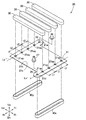
図2及び図3を参照する。冷却装置20は、円形状の複数の穴21ax、21ayが形成された板状のプレート部材21と、このプレート部材21の上面21b(第1面21b)に固定されている第1流路形成部材30と、プレート部材21の下面21c(第2面21c)に固定されている第2流路形成部材40x、40yと、プレート部材21に開けられた穴によって構成され低温の冷却媒体が流入する流体流入部25と、プレート部材21に開けられた穴によって構成され高温の冷却媒体が流出する流体流出部26と、流体流入部25に接続されている流入部接続部材27と、流体流出部26に接続されている流出部接続部材28と、を有する。
金属板製のプレート部材21は、略矩形状を呈し、流体流入部25及び流体流出部26の形成されている部位21d、21eがそれぞれの辺から突出している。換言すれば、冷却媒体の流入及び流出に必要な部位のみが突出部21d、21eとして、略矩形状の部位から突出して形成されている。プレート部材21には、第1流路形成部材30及び第2流路形成部材40x、40yによって覆われ、冷却媒体が通過可能な複数の穴21ax、21ayが開けられている。
プレート部材21は、ろう付けが可能な金属材料が用いられることが好ましい。例えば、アルミニウム合金、銅合金、ステンレス合金などが用いられる。
プレート部材21は、穴21ax、21ay、流体流入部25、流体流出部26の形成も含め、プレス成形やレーザ加工によって形成することができる。
穴21ax、21ayは、それぞれ同じ直径の円形状の穴である。穴21ax、21ayは、第1の穴グループ、及び、第2の穴グループの2つのグループに分けることができる。
第1の穴グループに属する穴21axは、プレート部材21の面上をX方向に延びる線Lx上に開けられている。換言すれば、平面視において、線Lxは、第1の穴グループに属する穴21axの中心(重心)を通過している。第1の穴グループに属する穴21axは、それぞれの間隔がt1となるよう等間隔に開けられている。
第2の穴グループに属する穴21ayは、プレート部材21の面上をY方向に延びる線Ly上に開けられている。換言すれば、平面視において、線Lyは、第2の穴グループに属する穴21ayの中心(重心)を通過している。第2の穴グループに属する穴21ayは、それぞれの間隔がt2となるよう等間隔に開けられている。
X方向に延びる線Lx及びY方向に延びる線Lyは、互いに平行に、且つ、長方形状のプレート部材21の一辺に平行に延びている。第1の穴グループに属する穴21ax同士の間隔t1は、第2の穴グループに属する穴21ay同士の間隔t2に等しい。つまり、t1=t2である。
なお、穴21ax、21ayの形状は、円形状以外の形状、例えば、長孔形状等であってもよい。また、1つ1つの穴の形状がそれぞれ異なっていてもよい。この場合であっても、線Lx、Lyが、穴21ax、21ayの中心(重心)を通過するよう、それぞれの穴21ax、21ayは、形成されていることが好ましい。
図3を参照する。第1流路形成部材30は、プレート部材21の一辺に対して直交する方向に、それぞれ平行に4つ設けられている。第1流路形成部材30は、それぞれ同じ部材が用いられ、プレート部材21に対して、例えば、ろう付けによって固定されている。
第1流路形成部材30は、例えば、アルミニウム合金、銅合金、ステンレス合金などにより形成される。ろう付け性を確保するために、第1流路形成部材30の材料は、プレート部材21と同系列の金属が選択される。
第1流路形成部材30は、第1の穴グループに属する穴21ax、及び、第2の穴グループに属する穴21ayを1つずつ覆っている。
図4を参照する。第1流路形成部材30は、それぞれ、断面が略U字状の第1空間を有し、プレート部材21の上面21bと第1空間とで冷却媒体の1面側流路R1を形成する。
なお、第1流路形成部材30は、穴21ax、21ayが形成される位置によっては、プレート部材21に対して直交する方向ではなく、斜めに配置されていてもよい(図示せず)。第1の穴グループに属する穴21axの各穴と、第2の穴グループに属する穴21ayの各穴とを、気密性を確保しつつ、同じ数ずつ(例えば、1つずつ)覆うように配置されていればよい。
図3及び図5を参照する。第2流路形成部材40x、40yは、断面が略U字状の第2空間を有し、第2面21cと第2空間とで冷却媒体の2面側流路R2を形成する。第2流路形成部材40x、40yは、プレート部材21に対して、例えば、ろう付けによって固定されている。
第2流路形成部材40x、40yは、例えば、アルミニウム合金、銅合金、ステンレス合金などにより形成される。ろう付け性を確保するために、第2流路形成部材40x、40yの材料は、プレート部材21と同系列の金属が選択される。
第2流路形成部材40x、40yは、プレート部材21の一辺に対して平行に、それぞれ平行に2つ設けられている。
なお、第2流路形成部材40x、40yは、穴21ax、21ayが形成される位置によっては、プレート部材21に対して直交する方向ではなく、斜めに配置されていてもよい(図示せず)。第1の穴グループに属する穴21axの各穴を、気密性を確保しつつ、覆うように配置されていればよい。あるいは、第2の穴グループに属する穴21ayの各穴を、気密性を確保しつつ、覆うように配置されていればよい。
第2流路形成部材40x、40yは、第1の穴グループに属する穴21ax及び流体流入部25に連通する一方側第2流路形成部材40xと、第2の穴グループに属する穴21ay及び流体流出部26に連通する他方側第2流路形成部材40yと、を有する。
一方側第2流路形成部材40xは、第1の穴グループに属する穴21axの全て、及び、流体流入部25を覆い、他方側第2流路形成部材40yは、第2の穴グループに属する穴21ayの全て、及び、流体流出部26を覆っている。
流体流入部25は、丸穴によって突出部21dに形成され、一方側第2流路形成部材40xの第2空間に臨んでいる。流体流入部25は、X方向に延びる線Lx上に形成されている。平面視において、線Lxは、流体流入部25の中心を通過している。
流体流出部26は、丸穴によって突出部21eに形成され、他方側第2流路形成部材40yの第2空間に臨んでいる。流体流出部26は、Y方向に延びる線Ly上に形成されている。平面視において、線Lyは、流体流出部26の中心を通過している。
冷却装置20の作用について説明する。
図1を参照する。流体冷却部12において冷却された冷却媒体は、冷却装置20に送られる。
図6を参照する。図6には、説明の便宜上、流入部接続部材27(図3参照)及び流出部接続部材28(図3参照)が外された冷却装置20が示されている。冷却媒体は、流体流入部25から一方側第2流路形成部材40xによって形成されている2面側流路R2に流入する。2面側流路R2を流れる冷却媒体の一部は、分岐点P1において分岐し、第1流路形成部材30-1(-1は、第1流路形成部材30を識別するための添え字。以下、図6において同じ。)によって形成された1面側流路R1を流れる。同様に、冷却媒体は、第1流路形成部材30-2~30-4に分岐され、それぞれによって形成された1面側流路R1を流れる。
第1流路形成部材30-1~30-4の上面には、高温のバッテリBa(図1参照)が熱的に結合するように載置されている。1面側流路R1を通過する冷却媒体は、第1流路形成部材30-1~30-4を介して、バッテリBaを冷却する。即ち、熱交換を行う。バッテリBaの熱によって温められた冷却媒体は、他方側第2流路形成部材40yによって形成された2面側流路R2に流れ、合流部P2において合流する。合流した冷却媒体は、流体流出部26から流出する。
図1を参照する。流体流出部26を通過して流出部接続部材28を流出した冷却媒体は、流体冷却部12に送られ、冷却され、再び冷却装置20に送られる。
ところで、流体流入部25からの流路長が最も短い第1流路形成部材30-1は、流体流出部26からの流路長が最も長い。一方、流体流入部25からの流路長が最も長い第1流路形成部材30-4は、流体流出部26からの流路長が最も短い。換言すれば、流体流入部25及び流体流出部26の位置は、流体流入部25からの流路長の最も短い第1流路形成部材30-1が、流体流出部26までの流路長が最も長くなり、流体流入部25からの流路長の最も長い第1流路形成部材30-4が、流体流出部26までの流路長が最も短くなるよう設定されている。
流体流入部25から流入し、流体流出部26から流出する冷却媒体の流路長は、いずれの第1流路形成部材30-1~30-4を通過した場合であっても同じである。
以上に説明した冷却装置20は、以下の効果を奏する。
図2を参照する。冷却装置20は、穴21ax、21ayが開けられているプレート部材21に、共に略U字状に形成された第1流路形成部材30及び第2流路形成部材40x、40yが重ねられてなる。プレート部材21に各流路形成部材30、40x、40yを重ね合わせることにより、各部品の位置決めを容易に行うことができる。位置決めが簡単で容易に組み立てることのできる車両用バッテリ冷却装置を提供することができる。
加えて、第1流路形成部材30は、第1の穴グループに属する穴21axのいずれかと、第2の穴グループに属する穴21ayのいずれかと、を連通している。そして、第2流路形成部材40x、40yは、第1の穴グループに属する穴21axに連通する一方側第2流路形成部材40xと、第2の穴グループに属する穴21ayに連通する他方側第2流路形成部材40yと、を有する。一方側第2流路形成部材40x、40yと他方側第2流路形成部材40x、40yとを用いて、複数配置された第1流路形成部材30が形成する複数の1面側流路R1(図6参照)に、冷却媒体を分配し、かつ回収することができる。
X方向と前記Y方向とは、平行であり、第1の穴グループに属する穴21axの数と、第2の穴グループに属する穴21ayの数と、は等しい。さらに、第1の穴グループに属する穴21axは、それぞれ等間隔(t1)に形成され、第2の穴グループに属する穴21ayは、それぞれ等間隔(t2)に形成されている。これらにより、複数の第1流路形成部材30をそれぞれ同じ部品で構成することができ、また一方側第2流路形成部材40x、40yと他方側第2流路形成部材40x、40yも同じ部品で構成することができる。部品の共通化を行って誤った位置への流路形成部材30、40x、40yの組付けを抑制し、組立作業の効率化を図ることができる。
図6を参照する。流体流入部25からの流路長が最も短い前記第1流路形成部材30-1は、流体流出部26からの流路長が最も長く、流体流入部25からの流路長が最も長い第1流路形成部材30-4は、流体流出部26からの流路長が最も短いように、流体流入部25及び流体流出部26が配置されている。流体流入部25から流入した冷却媒体は、一方側第2流路形成部材40x、第1流路形成部材30、他方側第2流路形成部材40yを通過し、流体流出部26から流出する。第1流路形成部材30が複数配置されている場合であっても、流体流入部25から流体流出部26に至る各流路の長さを等しくし、それぞれの流路に流れる冷却媒体の量を均等にすることができる。車両用バッテリBa(図1参照)の全体を効率よく冷却することができ、望ましい。
流体流入部25及び流体流出部26は、共にプレート部材21に開けられた穴によって構成されている。流体流入部25及び流体流出部26を、流路の一部を形成する穴21ax、21ayと一緒にプレス加工やレーザ加工によって形成することができる。加工に必要な工程が少なく済み、車両用バッテリ冷却装置20を安価にすることができる。
<実施例2>
次に、実施例2による冷却装置20Aを図面に基づいて説明する。
次に、実施例2による冷却装置20Aを図面に基づいて説明する。
図7を参照する。実施例2による冷却装置20Aにおいては、実施例1による冷却装置20(図3参照)に、さらに延長部50が設けられている。その他の基本的な構成については、実施例1による冷却装置と共通する。実施例1と共通する部分については、符号を流用すると共に、詳細な説明を省略する。
延長部50は、他方側第2流路形成部材40yに接続され第1流路形成部材30に平行に延びる第1部材51と、この第1部材51の端部から直交する方向に延びている第2部材52と、を有する。
第2部材52の端部に、流出部接続部材28が臨んでいる。流出部接続部材28は、流入部接続部材27に隣接して設けられている。つまり、流体流入部に隣接した位置に流体流出部が形成されている。
なお、実施例2による冷却装置20Aにおいても、流入部接続部材27から流入し、流出部接続部材28から流出する冷却媒体の流路長は、いずれの第1流路形成部材30を通過した場合であっても同じである。
以上に説明した車両用バッテリ冷却装置20Aも本発明所定の効果を奏する。
加えて、他方側第2流路形成部材40yには、流体流出部26が流体流入部25と隣接する位置となるように延長する延長部50が接続されている。流体流入部25と流体流出部26とを近接させることができ、例えば、流体冷却部12(図1参照)とへ接続するための配管の接続構造をコンパクトにすることができる。
なお、冷却媒体の流れを逆にし、流体流入部から延長部50を延ばし、流体流入部を流体流出部の近傍に配置した場合にも同様の効果を奏する。つまり、一方側第2流路形成部材には、流体流入部が流体流出部と隣接する位置となるように延長する延長部50が接続されていてもよい。この場合にも、車両用バッテリ冷却装置20Aの配管の接続構造をコンパクトにすることができる。
<実施例3>
次に、実施例3による冷却装置20Bを図面に基づいて説明する。
次に、実施例3による冷却装置20Bを図面に基づいて説明する。
図8を参照する。実施例3による冷却装置20Bは、流体導入部(流入部接続部材27)及び流体流出部(流出部接続部材28)がプレート部材21の同じ辺上に形成されている。その他の基本的な構成については、実施例1及び/又は実施例2による冷却装置20、20Aと共通する。実施例1及び/又は実施例2と共通する部分については、符号を流用すると共に、詳細な説明を省略する。
なお、冷却装置20Bにおいては、通過する第1流路形成部材30によって、流路長が異なる。この場合、流路長が最も短くなる第1流路形成部材30(図面一番下側の第1流路形成部材30)により多くの流体が流れる。バッテリBa(図1参照)の一部が特に高温となる場合には、このような部位に当接する第1流路形成部材30の流路長を短くすることにより、より多くの流体を流すことができる。これにより、効率的にバッテリBaを冷却することができる。
一方、各第1流路形成部材30によって構成される1面側流路R1により均一に流体を流すべく、穴21ax、21ayの大きさをそれぞれ異ならせることも可能である。例えば、流路長の長くなる部位における穴21ax、21ayの開口面積を、流路長の短くなる部位における穴21ax、21ayの開口面積よりも、相対的に大きくするように形成すればよい。
以上に説明した冷却装置20Bも本発明所定の効果を奏する。
冷却装置20Bは、略矩形板状のプレート部材21の同じ辺上に流体流入部(流入部接続部材27)及び流体流出部(流出部接続部材28)が形成されている。このため、延長部50(図7参照)を設けることなく、流体流入部及び流体流出部を近接して形成することができる。
尚、各実施例に記載された事項は、適宜組み合わせることも可能である。また、本発明の作用及び効果を奏する限りにおいて、本発明は、実施例に限定されるものではない。
本発明の車両用バッテリ冷却装置は、ハイブリッド車両に搭載するのに好適である。
20、20A、20B…車両用バッテリ冷却装置
21…プレート部材、21ax…第1の穴グループに属する穴、21ay…第2の穴グループに属する穴、21b…上面(第1面)、21c…下面(第2面)
25…流体流入部
26…流体流出部
30…第1流路形成部材
40x…一方側第2流路形成部材、40y…他方側第2流路形成部材
Lx…X方向に延びる線、Ly…Y方向に延びる線
R1…1面側流路
R2…2面側流路
Ba…車両用バッテリ
21…プレート部材、21ax…第1の穴グループに属する穴、21ay…第2の穴グループに属する穴、21b…上面(第1面)、21c…下面(第2面)
25…流体流入部
26…流体流出部
30…第1流路形成部材
40x…一方側第2流路形成部材、40y…他方側第2流路形成部材
Lx…X方向に延びる線、Ly…Y方向に延びる線
R1…1面側流路
R2…2面側流路
Ba…車両用バッテリ
Claims (6)
- 車両に搭載されたバッテリ(Ba)に接するように設けられ、内部を流れる冷却媒体によって前記バッテリ(Ba)を冷却する車両用バッテリ冷却装置(20;20A;20B)において、
複数の穴(21ax、21ay)が形成された板状のプレート部材(21)と、
断面が略U字状の第1空間を有し、前記プレート部材(21)の第1面(21b)と前記第1空間とで前記冷却媒体の1面側流路(R1)を形成する第1流路形成部材(30)と、
断面が略U字状の第2空間を有し、前記第1面(21b)の裏面である第2面(21c)と前記第2空間とで前記冷却媒体の2面側流路(R2)を形成する第2流路形成部材(40x、40y)と、を備え、
前記穴(21ax、21ay)は、前記プレート部材(21)の面上をX方向に沿って形成された第1の穴グループに属する複数の穴(21ax)と、前記プレート部材(21)の面上をY方向に沿って形成された第2の穴グループに属する複数の穴(21ay)と、のいずれかに属し、
前記第1流路形成部材(30)は、複数配置され、前記1面側流路(R1)が前記第1の穴グループに属する穴(21ax)のいずれかと、前記第2の穴グループに属する穴(21ay)のいずれかと、を連通し、
前記第2流路形成部材(40x、40y)は、前記第1の穴グループに属する穴(21ax)に連通する一方側第2流路形成部材(40x)と、前記第2の穴グループに属する穴(21ay)に連通する他方側第2流路形成部材(40y)と、を有することを特徴とする車両用バッテリ冷却装置。 - 前記X方向と前記Y方向とは、平行であり、
前記第1の穴グループに属する穴(21ax)の数と、前記第2の穴グループに属する穴(21ay)の数と、は等しく、
前記第1の穴グループに属する穴(21ax)は、それぞれ等間隔に形成され、
前記第2の穴グループに属する穴(21ay)は、それぞれ等間隔に形成されていることを特徴とする請求項1記載の車両用バッテリ冷却装置。 - 前記一方側第2流路形成部材(40x)の第2空間に臨むよう配置されて前記冷却媒体が流入する流体流入部(25)と、前記他方側第2流路形成部材(40y)の第2空間に臨むよう配置されて前記冷却媒体が流出する流体流出部(26)と、をさらに有し、
前記2面側流路(R2)の長さを基準としたときに、前記流体流入部(25)からの流路長が最も短い前記第1流路形成部材(30)は、前記流体流出部(26)からの流路長が最も長く、前記流体流入部(25)からの流路長が最も長い前記第1流路形成部材(30)は、前記流体流出部(26)からの流路長が最も短いように、前記流体流入部(25)及び前記流体流出部(26)が配置されていることを特徴とする請求項2記載の車両用バッテリ冷却装置。 - 前記流体流入部(25)及び前記流体流出部(26)は、共に前記プレート部材(21)に開けられた穴によって構成されていることを特徴とする請求項3記載の車両用バッテリ冷却装置。
- 前記他方側第2流路形成部材(40y)には、前記流体流出部(26)が前記流体流入部(25)と隣接する位置となるように延長する延長部(50)が接続されていることを特徴とする請求項3または請求項4のいずれかに記載の車両用バッテリ装置。
- 前記一方側第2流路形成部材(40x)には、前記流体流入部(25)が前記流体流出部(26)と隣接する位置となるように延長する延長部(50)が接続されていることを特徴とする請求項3または請求項4のいずれかに記載の車両用バッテリ装置。
Priority Applications (2)
| Application Number | Priority Date | Filing Date | Title |
|---|---|---|---|
| CN202080019689.6A CN113544898B (zh) | 2019-03-19 | 2020-03-16 | 车辆用电池冷却装置 |
| JP2021507339A JP7101449B2 (ja) | 2019-03-19 | 2020-03-16 | 車両用バッテリ冷却装置 |
Applications Claiming Priority (2)
| Application Number | Priority Date | Filing Date | Title |
|---|---|---|---|
| JP2019-051308 | 2019-03-19 | ||
| JP2019051308 | 2019-03-19 |
Publications (1)
| Publication Number | Publication Date |
|---|---|
| WO2020189622A1 true WO2020189622A1 (ja) | 2020-09-24 |
Family
ID=72519271
Family Applications (1)
| Application Number | Title | Priority Date | Filing Date |
|---|---|---|---|
| PCT/JP2020/011452 Ceased WO2020189622A1 (ja) | 2019-03-19 | 2020-03-16 | 車両用バッテリ冷却装置 |
Country Status (3)
| Country | Link |
|---|---|
| JP (1) | JP7101449B2 (ja) |
| CN (1) | CN113544898B (ja) |
| WO (1) | WO2020189622A1 (ja) |
Citations (4)
| Publication number | Priority date | Publication date | Assignee | Title |
|---|---|---|---|---|
| WO2012062712A1 (fr) * | 2010-11-10 | 2012-05-18 | Valeo Systemes Thermiques | Echangeur de chaleur pour dispositif de stockage d'energie electrique |
| JP2013134993A (ja) * | 2011-12-22 | 2013-07-08 | Samsung Sdi Co Ltd | バッテリモジュール |
| WO2014162939A1 (ja) * | 2013-04-01 | 2014-10-09 | カルソニックカンセイ株式会社 | 温調装置 |
| JP2018512553A (ja) * | 2015-03-20 | 2018-05-17 | ヴァレオ システム テルミク | 電動車両又はハイブリッド車両のバッテリー用の熱交換器及び熱管理設備 |
Family Cites Families (11)
| Publication number | Priority date | Publication date | Assignee | Title |
|---|---|---|---|---|
| JP2011175911A (ja) * | 2010-02-25 | 2011-09-08 | Sanyo Electric Co Ltd | 電池冷却/加熱構造及び電池モジュール |
| CN201966304U (zh) * | 2011-02-24 | 2011-09-07 | 上海空间电源研究所 | 电动汽车锂离子蓄电池组的散热水冷板 |
| WO2013098982A1 (ja) * | 2011-12-28 | 2013-07-04 | 日立ビークルエナジー株式会社 | 電池モジュール、電池ブロック、及び、電池パック |
| JP5738817B2 (ja) * | 2012-09-14 | 2015-06-24 | 日立オートモティブシステムズ株式会社 | 電力変換装置 |
| JP5899132B2 (ja) * | 2013-01-31 | 2016-04-06 | 日立オートモティブシステムズ株式会社 | 蓄電モジュール |
| US20180123201A1 (en) * | 2016-10-28 | 2018-05-03 | Inevit, Llc | Battery module cooling tube including an integrated turbulator component and method thereof |
| CN106684500A (zh) * | 2017-01-17 | 2017-05-17 | 北京新能源汽车股份有限公司 | 一种电池模组的热管理系统及电动汽车 |
| KR101929988B1 (ko) * | 2017-07-19 | 2018-12-18 | 주식회사 고산 | 배터리 냉각용 열교환기 |
| CN208298881U (zh) * | 2018-02-08 | 2018-12-28 | 比亚迪股份有限公司 | 动力电池包及车辆 |
| CN207967246U (zh) * | 2018-03-27 | 2018-10-12 | 浙江吉利汽车研究院有限公司 | 液冷板组件及汽车电池系统 |
| CN109149007B (zh) * | 2018-08-30 | 2020-12-25 | 奇瑞新能源汽车股份有限公司 | 一种电动汽车动力电池用液冷板 |
-
2020
- 2020-03-16 JP JP2021507339A patent/JP7101449B2/ja active Active
- 2020-03-16 WO PCT/JP2020/011452 patent/WO2020189622A1/ja not_active Ceased
- 2020-03-16 CN CN202080019689.6A patent/CN113544898B/zh active Active
Patent Citations (4)
| Publication number | Priority date | Publication date | Assignee | Title |
|---|---|---|---|---|
| WO2012062712A1 (fr) * | 2010-11-10 | 2012-05-18 | Valeo Systemes Thermiques | Echangeur de chaleur pour dispositif de stockage d'energie electrique |
| JP2013134993A (ja) * | 2011-12-22 | 2013-07-08 | Samsung Sdi Co Ltd | バッテリモジュール |
| WO2014162939A1 (ja) * | 2013-04-01 | 2014-10-09 | カルソニックカンセイ株式会社 | 温調装置 |
| JP2018512553A (ja) * | 2015-03-20 | 2018-05-17 | ヴァレオ システム テルミク | 電動車両又はハイブリッド車両のバッテリー用の熱交換器及び熱管理設備 |
Also Published As
| Publication number | Publication date |
|---|---|
| JP7101449B2 (ja) | 2022-07-15 |
| JPWO2020189622A1 (ja) | 2021-10-21 |
| CN113544898B (zh) | 2023-04-28 |
| CN113544898A (zh) | 2021-10-22 |
Similar Documents
| Publication | Publication Date | Title |
|---|---|---|
| JP6064730B2 (ja) | 冷却装置 | |
| KR20210157429A (ko) | 고성능 균일 온도 냉각판 | |
| CN113875073B (zh) | 电池冷却系统 | |
| JP5585543B2 (ja) | 車両用冷却装置 | |
| CN108461862A (zh) | 蓄能器设备和机动车 | |
| US9175886B2 (en) | Heat exchanger having thermoelectric element | |
| JP2013234801A (ja) | 熱交換器および車両用空調装置 | |
| JP6969978B2 (ja) | 伝熱装置 | |
| KR100687637B1 (ko) | 열교환기 | |
| EP3819580B1 (en) | A heat exchanger | |
| CN111919332A (zh) | 用于机动车辆电池单元的冷却系统 | |
| JP6922645B2 (ja) | 熱交換器 | |
| US11268769B2 (en) | Heat exchanger | |
| US6397938B1 (en) | Heat exchanger | |
| JP7101449B2 (ja) | 車両用バッテリ冷却装置 | |
| WO2017086269A1 (ja) | 蓄冷熱交換器 | |
| EP0869325A2 (en) | In-line integrated heat exchanger | |
| US7845392B2 (en) | Heat exchanger assembly | |
| KR20130054048A (ko) | 차량용 라디에이터 | |
| JPH0650675A (ja) | 熱交換器 | |
| WO2014181687A1 (ja) | 蓄冷熱交換器 | |
| US20170106740A1 (en) | Heat exchanger for vehicle and heat exchanging system having the same | |
| KR20220153825A (ko) | 열교환기 | |
| JP2018146216A (ja) | 複数流路熱交換器 | |
| CN110214393B (zh) | 高压蓄能装置以及具有高压蓄能装置的车辆 |
Legal Events
| Date | Code | Title | Description |
|---|---|---|---|
| 121 | Ep: the epo has been informed by wipo that ep was designated in this application |
Ref document number: 20773292 Country of ref document: EP Kind code of ref document: A1 |
|
| ENP | Entry into the national phase |
Ref document number: 2021507339 Country of ref document: JP Kind code of ref document: A |
|
| NENP | Non-entry into the national phase |
Ref country code: DE |
|
| 122 | Ep: pct application non-entry in european phase |
Ref document number: 20773292 Country of ref document: EP Kind code of ref document: A1 |