WO2020189619A1 - 把持システムおよび把持方法 - Google Patents
把持システムおよび把持方法 Download PDFInfo
- Publication number
- WO2020189619A1 WO2020189619A1 PCT/JP2020/011410 JP2020011410W WO2020189619A1 WO 2020189619 A1 WO2020189619 A1 WO 2020189619A1 JP 2020011410 W JP2020011410 W JP 2020011410W WO 2020189619 A1 WO2020189619 A1 WO 2020189619A1
- Authority
- WO
- WIPO (PCT)
- Prior art keywords
- pushing
- bag
- shaped object
- fingers
- gripping
- Prior art date
- Legal status (The legal status is an assumption and is not a legal conclusion. Google has not performed a legal analysis and makes no representation as to the accuracy of the status listed.)
- Ceased
Links
Images






Classifications
-
- B—PERFORMING OPERATIONS; TRANSPORTING
- B25—HAND TOOLS; PORTABLE POWER-DRIVEN TOOLS; MANIPULATORS
- B25J—MANIPULATORS; CHAMBERS PROVIDED WITH MANIPULATION DEVICES
- B25J15/00—Gripping heads and other end effectors
- B25J15/08—Gripping heads and other end effectors having finger members
- B25J15/10—Gripping heads and other end effectors having finger members with three or more finger members
-
- B—PERFORMING OPERATIONS; TRANSPORTING
- B25—HAND TOOLS; PORTABLE POWER-DRIVEN TOOLS; MANIPULATORS
- B25J—MANIPULATORS; CHAMBERS PROVIDED WITH MANIPULATION DEVICES
- B25J13/00—Controls for manipulators
- B25J13/08—Controls for manipulators by means of sensing devices, e.g. viewing or touching devices
- B25J13/081—Touching devices, e.g. pressure-sensitive
- B25J13/082—Grasping-force detectors
-
- B—PERFORMING OPERATIONS; TRANSPORTING
- B25—HAND TOOLS; PORTABLE POWER-DRIVEN TOOLS; MANIPULATORS
- B25J—MANIPULATORS; CHAMBERS PROVIDED WITH MANIPULATION DEVICES
- B25J15/00—Gripping heads and other end effectors
- B25J15/0009—Gripping heads and other end effectors comprising multi-articulated fingers, e.g. resembling a human hand
-
- B—PERFORMING OPERATIONS; TRANSPORTING
- B25—HAND TOOLS; PORTABLE POWER-DRIVEN TOOLS; MANIPULATORS
- B25J—MANIPULATORS; CHAMBERS PROVIDED WITH MANIPULATION DEVICES
- B25J15/00—Gripping heads and other end effectors
- B25J15/08—Gripping heads and other end effectors having finger members
-
- B—PERFORMING OPERATIONS; TRANSPORTING
- B25—HAND TOOLS; PORTABLE POWER-DRIVEN TOOLS; MANIPULATORS
- B25J—MANIPULATORS; CHAMBERS PROVIDED WITH MANIPULATION DEVICES
- B25J9/00—Program-controlled manipulators
- B25J9/16—Program controls
- B25J9/1612—Program controls characterised by the hand, wrist, grip control
-
- G—PHYSICS
- G05—CONTROLLING; REGULATING
- G05B—CONTROL OR REGULATING SYSTEMS IN GENERAL; FUNCTIONAL ELEMENTS OF SUCH SYSTEMS; MONITORING OR TESTING ARRANGEMENTS FOR SUCH SYSTEMS OR ELEMENTS
- G05B2219/00—Program-control systems
- G05B2219/30—Nc systems
- G05B2219/39—Robotics, robotics to robotics hand
- G05B2219/39486—Fingered hand, multifingered hand
Definitions
- the present invention relates to a gripping system for gripping an object with a plurality of fingers and a gripping method.
- Patent Document 1 discloses a hand mechanism including three fingers. In the hand mechanism of Patent Document 1, the three fingers have the same structure.
- a bag-shaped object in which a fluid (gas or liquid) is enclosed may be the object.
- a fluid gas or liquid
- its shape tends to change. Therefore, as compared with an object that is hard to be deformed, a frictional force is hard to work, and it may be difficult to maintain a state in which the bag-shaped object is sandwiched by a plurality of fingers.
- the present invention has been made in view of the above problems, and in a gripping system provided with a hand mechanism for gripping an object by a plurality of fingers, a bag-shaped object filled with fluid is stably gripped.
- the purpose is to provide a technology that is possible.
- a gripping system including a hand mechanism for gripping an object with a plurality of fingers and a control device for controlling the hand mechanism when gripping the object, wherein the object has a fluid inside the object.
- a hand mechanism for gripping an object with a plurality of fingers
- a control device for controlling the hand mechanism when gripping the object, wherein the object has a fluid inside the object.
- at least one finger portion of the plurality of finger portions of the hand mechanism is used as a pushing finger portion, and the finger portion serving as the pushing finger portion in the hand mechanism.
- the control device makes the tip of the pushing finger portion of the hand mechanism into the bag-shaped object.
- the pressure is brought into contact with the bag-shaped object and then pushed into the bag-shaped object, and then the pressure detected by the pressure detecting unit provided on one pushing finger portion, or the pressure detecting unit provided on each pushing finger portion. After any of the pressures detected by This is performed with the portion pushed into the bag-shaped object.
- a bag-shaped object in which a fluid is sealed can be stably gripped.
- FIG. 2 is a second diagram showing a schematic configuration of a gripping system according to an embodiment. It is a perspective view of the hand mechanism which concerns on embodiment. It is a top view of the hand mechanism which concerns on embodiment. It is a figure which shows the movable range of the 2nd joint part in the finger part of the hand mechanism which concerns on Example. It is a figure which shows the movable range of the 1st joint part in the finger part of the hand mechanism which concerns on Example. It is a block diagram which shows each functional part included in the arm control device and the hand control device which concerns on embodiment. It is a figure which shows the form of the hand mechanism at the time of performing a pushing operation which concerns on Example 1.
- FIG. It is a figure which shows the state of the hand mechanism and the bag-shaped object at the time of performing a pushing operation which concerns on Example 1.
- FIG. It is a figure which shows the state of the hand mechanism and the bag-shaped object at the time of performing a gripping operation which concerns on Example 1.
- FIG. FIG. 5 is a flowchart showing a control flow of a gripping system when gripping a bag-shaped object according to the first embodiment. It is a figure for demonstrating the pushing operation and the grasping operation which concerns on Example 2.
- the gripping system includes a hand mechanism for gripping an object with a plurality of fingers and a control device for controlling the hand mechanism.
- the object to be gripped by the hand mechanism may be a bag-shaped object in which a fluid is sealed.
- a fluid such as a gas or a liquid
- the bag-shaped object is less likely to be deformed when an external force is applied. Therefore, when the gripping operation, which is the operation of pinching the bag-shaped object by the fingers of the hand mechanism, if the internal pressure of the bag-shaped object is high, the bag-shaped object is pressed by the fingers in the gripping operation. Occasionally, the bag-shaped object is difficult to deform. As a result, the reaction force from the bag-shaped object to the finger portion that sandwiches the bag-shaped object becomes large. Therefore, it is possible to increase the frictional force between the finger portion that sandwiches the bag-shaped object and the bag-shaped object.
- the gripping system when the object is a bag-shaped object in which a fluid is sealed, at least one of the plurality of fingers of the hand mechanism is pushed. And. At this time, a pressure detecting unit is provided at the tip of the finger portion that serves as the pushing finger portion in the hand mechanism. Here, the pressure detecting unit detects the pressure applied to the tip of the finger.
- the control device brings the tip of the pushing finger portion of the hand mechanism into contact with the bag-shaped object and pushes it into the bag-shaped object before executing the gripping operation by the hand mechanism (hereinafter, such an operation). May be referred to as "pushing operation").
- this pushing operation is performed, the bag-shaped object is deformed and its internal pressure is increased. Further, as the amount of pushing the pushing finger portion into the bag-shaped object in the pushing operation increases, the internal pressure of the bag-shaped object increases. Along with this, the pressure detected by the pressure detecting unit provided at the tip of the pushing finger portion increases.
- the control device starts the gripping operation after any of the pressures detected by the pressure detection unit provided on each pushing finger portion becomes equal to or higher than a predetermined pressure.
- the control device executes the gripping operation while maintaining the state in which the pushing finger portion is pushed into the bag-shaped object.
- the predetermined pressure is applied because a sufficient reaction force acts on the finger portion from the bag-shaped object when the bag-shaped object is pinched by the finger portion of the hand mechanism in the gripping operation. It is a pressure that makes it possible to secure a sufficient frictional force for gripping between the finger portion and the bag-shaped object.
- the gripping operation can be executed with the internal pressure of the bag-shaped object sufficiently increased by performing the pushing operation before performing the gripping operation. Therefore, in the gripping operation, when the finger portion of the hand mechanism is pressed against the bag-shaped object, a sufficient frictional force is secured between the finger portion and the bag-shaped object. Therefore, it becomes easy to maintain the state in which the bag-shaped object is sandwiched between the plurality of fingers. As a result, the bag-shaped object can be stably gripped by the hand mechanism.
- the pushing operation is performed in a state where the distance between the tips of the pushing fingers is a predetermined distance or more.
- the pushing operation is performed in a state where the distance between the tips of the pushing fingers is a predetermined distance or more.
- the pushing amount of the pushing finger portion with respect to the bag-shaped object is reduced, the time required from the start of the pushing operation to the start of the gripping operation can be shortened. As a result, the takt time related to gripping the bag-shaped object can be shortened.
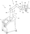
- Example 1> 1 and 2 are diagrams showing a schematic configuration of a gripping system according to this embodiment.
- the gripping system 1 includes a hand mechanism 2, an arm mechanism 3, and a pedestal portion 4 for gripping the object 10.
- the detailed configuration of the arm mechanism 3, the hand mechanism 2, and the pedestal portion 4 in the gripping system 1 will be described.
- a hand mechanism 2 is attached to one end of the arm mechanism 3. Further, the other end of the arm mechanism 3 is attached to the pedestal portion 4.
- the arm mechanism 3 includes a first arm link portion 31, a second arm link portion 32, a third arm link portion 33, a fourth arm link portion 34, a fifth arm link portion 35, and a connecting member 36.
- the base portion 20 of the hand mechanism 2 is connected to the first joint portion 30a formed on one end side of the first arm link portion 31 of the arm mechanism 3.
- the first joint portion 30a is provided with a motor (not shown) for rotating the hand mechanism 2 around the axis of the first arm link portion 31 with respect to the first arm link portion 31.
- the other end side of the first arm link portion 31 is connected to one end side of the second arm link portion 32 by the second joint portion 30b.
- the first arm link portion 31 and the second arm link portion 32 are connected so that their central axes intersect vertically.
- a motor for rotating the first arm link portion 31 with respect to the second arm link portion 32 around the axis of the second arm link portion 32 around the other end side. (Not shown) is provided.
- the other end side of the second arm link portion 32 is connected to one end side of the third arm link portion 33 by the third joint portion 30c.
- the third joint portion 30c is provided with a motor (not shown) for rotating the second arm link portion 32 relative to the third arm link portion 33.
- the other end side of the third arm link portion 33 is connected to one end side of the fourth arm link portion 34 by the fourth joint portion 30d. Further, the other end side of the fourth arm link portion 34 is connected to the fifth arm link portion 35 by the fifth joint portion 30e.
- the fourth joint portion 30d is provided with a motor (not shown) for rotating the third arm link portion 33 relative to the fourth arm link portion 34.
- the fifth joint portion 30e is provided with a motor (not shown) for rotating the fourth arm link portion 34 relative to the fifth arm link portion 35.
- the fifth arm link portion 35 is connected to the connecting member 36 vertically arranged from the pedestal portion 4 by the sixth joint portion 30f.
- the fifth arm link portion 35 and the connecting member 36 are connected so that their central axes are coaxial.
- the sixth joint portion 30f is provided with a motor (not shown) for rotating the fifth arm link portion 35 around the axis of the fifth arm link portion 35 and the connecting member 36.
- a motor not shown
- the arm mechanism 3 can be a mechanism having 6 degrees of freedom.
- FIG. 3 is a perspective view of the hand mechanism 2.
- FIG. 4 is a top view of the hand mechanism 2.
- the arrows indicate the rotatable range of each finger portion 21.
- the hand mechanism 2 includes a base portion 20 connected to the arm mechanism 3 and four finger portions 21 provided on the base portion 20. Further, as shown in FIGS. 3 and 4, in the hand mechanism 2, the four finger portions 21 on the base portion 20 are centered on the axis in the longitudinal direction of the hand mechanism 2 (the direction perpendicular to the paper surface in FIG. 4). They are arranged at equal angular intervals (that is, 90 deg intervals) on the circumference of the circle. Further, all four finger portions 21 have the same structure and the same length. However, the operation of each finger portion 21 is controlled independently.
- each finger portion 21 has a first finger link portion 211, a second finger link portion 212, and a base end portion 213. Then, the base end portion 213 of the finger portion 21 is connected to the base portion 20.
- the base end portion 213 is rotatably connected to the base portion 20 in the longitudinal direction of the finger portion 21 (the direction perpendicular to the paper surface in FIG. 4).
- one end of the second finger link portion 212 is connected to the base end portion 213.
- a second joint portion 23 is formed at the connecting portion between the second finger link portion 212 and the proximal end portion 213.
- a motor for rotationally driving the base end portion 213 and a motor for rotationally driving the second finger link portion 212 relative to the base end portion 213 are provided inside the base portion 20 .
- the base end portion 213 is rotationally driven, and accordingly, the entire finger portion 21 is rotationally driven within the range indicated by the arrow in FIG.
- the second joint portion 23 is formed so as to be flexible and extendable.
- one end of the first finger link portion 211 is connected to the other end of the second finger link portion 212.
- the first joint portion 22 is formed at the connecting portion between the first finger link portion 211 and the second finger link portion 212.
- a motor for rotationally driving the first finger link portion 211 relative to the second finger link portion 212 is provided inside the second finger link portion 212.
- the first joint portion 22 is formed so as to be flexible and extendable.
- the pressure sensor 70 is provided on the tip end side of the first finger link portion 211 of the finger portion 21.
- the pressure-sensitive sensor 70 is a sensor that detects an external force (pressure) acting on the tip of the first finger link portion 211.
- the arm control device 42 is a control device for controlling the arm mechanism 3 of the gripping system 1.
- the hand control device 43 is a control device for controlling the hand mechanism 2 of the gripping system 1.
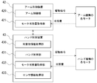
- FIG. 7 is a block diagram showing each functional unit included in the arm control device 42 and the hand control device 43.
- the arm control device 42 includes a plurality of drivers that generate drive signals for driving the motors provided at each joint of the arm mechanism 3, so that the drive signals from each driver are supplied to the corresponding motors. It is composed of. Further, the arm control device 42 includes a computer having an arithmetic processing unit and a memory. The arm control device 42 has an arm control unit 420 and a motor state quantity acquisition unit 421 as functional units. These functional units are formed by executing a predetermined control program in the computer included in the arm control device 42.
- the arm control unit 420 supplies drive signals from each driver based on the object information acquired by the object information acquisition unit 430 described later, which is a functional unit of the hand control device 43, so that each of the arm mechanisms 3 It controls the motors provided at the joints 30a, 30b, 30c, 30d, 30e, and 30f. Then, the arm control unit 420 moves the arm mechanism 3 by controlling each motor, whereby the position of the hand mechanism 2 is set to a desired position (a position where the object 10 can be gripped by the hand mechanism 2). Move to. Further, the motors provided at the joints 30a, 30b, 30c, 30d, 30e, and 30f of the arm mechanism 3 detect a state amount (rotational position, rotation speed, etc.
- the state amount of each motor detected by the encoder of each motor is input to the motor state amount acquisition unit 421 of the arm control device 42. Then, the arm control unit 420 servo-controls each motor so that the hand mechanism 2 moves to a desired position based on the state amount of each motor input to the motor state amount acquisition unit 421.
- the hand control device 43 includes a plurality of drivers for generating drive signals for driving each motor provided in the hand mechanism 2, so that the drive signals from each driver are supplied to the corresponding motors. It is composed. Further, the hand control device 43 includes a computer having an arithmetic processing unit and a memory. The hand control device 43 has an object information acquisition unit 430, a hand control unit 431, a motor state quantity acquisition unit 432, and a sensor information acquisition unit 433 as functional units. These functional units are formed by executing a predetermined control program in the computer included in the hand control device 43.
- the object information acquisition unit 430 acquires the object information which is the information about the object to be grasped by the hand mechanism 2.
- the object information includes information on the type, shape, dimensions, and position of the object, and environmental information around the object (information on objects other than the object existing around the object). For example, information on the shape of the container in which the object is housed and the arrangement of the objects in the container) and the like are included.
- the object information acquisition unit 430 may acquire the object information input by the user. Further, when a visual sensor for capturing an image including an object is provided, the object information acquisition unit 430 may acquire the object information from the image captured by the visual sensor.
- the hand control unit 431 controls each motor that drives each finger portion 21 of the hand mechanism 2 by supplying a drive signal from each driver based on the object information acquired by the object information acquisition unit 430. To do. As a result, the object 10 is gripped by the plurality of finger portions 21 of the hand mechanism 2. Further, each motor of the hand mechanism 2 is provided with an encoder (not shown) for detecting a state amount (rotational position, rotation speed, etc. of the rotation axis of the motor) related to each rotation state. Then, the state amount of each motor detected by the encoder of each motor is input to the motor state amount acquisition unit 432 of the hand control device 43. Then, the hand control unit 431 servos each motor in each finger portion 21 so that the object is gripped by the plurality of finger portions 21 based on the state quantity of each motor input to the motor state quantity acquisition unit 432. Control.
- the hand control device 43 has a sensor information acquisition unit 433.
- the detection value of the pressure-sensitive sensor 70 provided in the first finger link portion 211 of each finger portion 21 of the hand mechanism 2 is input to the sensor information acquisition unit 433.
- the hand control unit 431 may control each motor in each finger portion 21 based on the detection signal when the contact with the object of each finger portion 21 is detected by each pressure sensor 70. it can.
- the arm control device 42 and the hand control device 43 are shown separately as the control device included in the gripping system, but as another method, both devices are integrated in each functional unit. It is also possible to adopt a configuration formed in one control device. Further, even when the control device included in the gripping system is divided into the arm control device 42 and the hand control device 43, each functional unit shown in FIG. 7 is substantially any of them as long as no technical discrepancy occurs. It suffices if it is formed in the control device, and appropriate information can be exchanged between the arm control device 42 and the hand control device 43 as needed. Further, it is also possible to adopt a configuration in which a part of each functional unit in the arm control device 42 or the hand control device 43 is formed in a control device separate from the arm control device 42 and the hand control device 43. ..
- the gripping object 10 may be a bag-shaped object in which a fluid (gas or liquid) is sealed.
- a bag containing sweets such as potato chips and popcorn can be exemplified.
- a bag containing pickles and a bag containing a liquid detergent can be exemplified.
- the hand mechanism 2 tries to grip the bag-shaped object 10 in which the fluid is sealed, it may be referred to as a finger portion 21 (hereinafter, a gripping finger portion) used for gripping. ),
- the shape of the bag-shaped object 10 is likely to change.
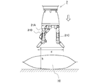
- FIG. 8 is a diagram showing a form of the hand mechanism 2 when performing a pushing operation using the fingers 21A and 21C.
- the illustration of the finger portion 21B is omitted for convenience.
- the white arrows in FIG. 8 indicate the pushing direction with respect to the bag-shaped object 10.
- the arm control unit 420 controls the arm mechanism 3 to move the hand mechanism 2 to a position suitable for the pushing operation by the fingers 21A and 21C. That is, the arm control unit 420 moves the hand mechanism 2 to a position where the tips of the fingers 21A and 21C can be brought into contact with the bag-shaped object 10 by moving the hand mechanism 2 in the pushing direction. Further, the hand control unit 431 controls the form of each finger portion 21 so that the tip portions of the pushing finger portions 21A and 21C can be brought into contact with the bag-shaped object 10. At that time, the distance d between the tip portions of the pushing finger portions 21A and 21C is set to be a predetermined distance or more.
- the height h of the tips of the pushing fingers 21A and 21C with respect to the plane perpendicular to the pushing direction is the same.
- the tip portions of the pushing finger portions 21A and 21C can be easily brought into contact with the bag-shaped object 10.
- the tips of the pushing fingers 21A and 21C can be pushed evenly against the bag-shaped object 10.
- the heights of the tips of the pushing fingers 21A and 21C with respect to the plane perpendicular to the pushing direction do not necessarily have to be the same. That is, in the pushing operation, the tip portions of the pushing finger portions 21A and 21B may be arranged so that the tip portions can be brought into contact with the bag-shaped object 10.
- the height of the tips of the fingers 21B and 21D that are not used for the pushing operation with respect to the plane perpendicular to the pushing direction is higher than the height h.
- the control for realizing the form for the pushing operation as described above includes information on the type, shape, dimensions, and position of the object of the bag-shaped object 10 acquired by the object information acquisition unit 430. It is executed based on the object information.
- the user can appropriately determine the pushing position of the pushing finger portion of the bag-shaped object 10 and the pushing direction of the pushing finger portion.
- the hand control unit 431 and the arm control unit 420 may determine these push-in positions and push-in directions based on the object information acquired by the object information acquisition unit 430.
- the pushing finger portion is not limited to the finger portions 21A and 21C, and other finger portions 21 may be combined.
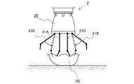
- FIG. 9 is a diagram showing the state of the hand mechanism 2 and the bag-shaped object 10 when the pushing operation is executed on the bag-shaped object 10 by the pushing fingers 21A and 21C.
- the white arrows in FIG. 9 indicate the pushing direction with respect to the bag-shaped object 10.
- the pushing amount is the pushing in the pushing direction (the direction of the white arrow in FIG. 9) from the position where the tips of the pushing fingers 21A and 21C come into contact with the bag-shaped object 10 after the pushing operation is started. It can be defined as the displacement amount of the tip portions of the finger portions 21A and 21C.
- the broken line in FIG. 9 illustrates the bag-shaped object 10 when the pushing fingers 21A and 21C come into contact with the bag-shaped object 10.
- the pushing amount of the pushing fingers 21A and 21C when the pushing operation is being executed is described as L.
- the pressure sensor 70 installed at the tips of the pushing fingers 21A and 21C detects the pressure received from the bag-shaped object 10. Therefore, when the internal pressure of the bag-shaped object 10 increases as the pushing amount of the pushing fingers 21A and 21C into the bag-shaped object 10 increases, the pushing fingers 21A and 21C are installed at the tips of the pushing fingers 21A and 21C. The pressure detected by the pressure-sensitive sensor 70 also increases.
- the sensor information acquisition unit 433 acquires the pressure detected by the pressure-sensitive sensors 70 provided on the pushing finger portions 21A and 21C as independent values.
- the arm control unit 420 stops driving the arm mechanism 3 for moving the hand mechanism 2 in the direction of the white arrow in FIG. As a result, the pushing operation on the bag-shaped object 10 is stopped.
- the predetermined pressure secures a sufficient frictional force between the gripping finger portion used for gripping and the bag-shaped object 10 in the gripping operation described later to realize gripping of the object.
- the pressure that can be.
- the predetermined pressure can be appropriately determined by the user based on an experiment or the like.
- the sensor information acquisition unit 433 may determine based on the object information acquired by the object information acquisition unit 430.
- the hand control unit 431 controls the motors of the pushing fingers 21A and 21C so that the positions of the tips of the pushing fingers 21A and 21C are not changed by the hand mechanism 2. Servo control is performed.
- the pressure sensor 70 is installed on all the finger portions 21 of the hand mechanism 2. However, in order to realize the pushing operation, the pressure-sensitive sensor 70 must be installed at least at the tip of the finger portion (finger portion 21A and finger portion 21C in this embodiment) to be the pushing finger portion. Good. If the pressure-sensitive sensor 70 is installed at the tip of the pushing finger, it can be determined whether or not the internal pressure of the bag-shaped object 10 has risen to the extent that the gripping operation is possible.
- FIG. 10 is a diagram showing the state of the hand mechanism 2 and the bag-shaped object 10 when the gripping operation is performed by using the finger portions 21A and 21C used as the pushing finger portions in the pushing operation as the gripping fingers. is there.
- the gripping operation is executed after the pushing operation is stopped.
- the gripping operation is executed while maintaining the state in which the pushing fingers 21A and 21C are pushed into the bag-shaped object 10 when the pushing operation is stopped. More specifically, as shown in FIG.
- the hand control unit 431 uses the finger portions 21A and 21C used as the pushing finger portion as the gripping finger portion, and the gripping finger portions 21A and 21C have a bag shape. While maintaining the state of being pushed into the object 10, the first joint portions 22A and 22C are bent (in FIG. 10, the arrows indicate the flexion of the first joint portions 22A and 22C of the finger portions 21A and 21C. It shows the direction.) As a result, by shortening the distance between the tip portions of the gripping finger portions 21A and 21C, the gripping operation which is the operation of sandwiching the bag-shaped object 10 by the gripping finger portions 21A and 21C is realized.
- the hand control unit 431 may realize the gripping operation by bending the second joint portions 23A and 23C of the gripping finger portions 21A and 21C, respectively.
- the tips of the fingers 21A and 21C at the time when the pushing operation is stopped The pushing amount (pushing amount L in FIG. 9) with respect to the bag-shaped object 10 is maintained. Therefore, a sufficient reaction force is applied to the gripping fingers 21A and 21C from the bag-shaped object 10. Therefore, a sufficient frictional force is generated between the gripping fingers 21A and 21C and the bag-shaped object 10 to realize gripping of the bag-shaped object 10. Therefore, the state in which the bag-shaped object 10 is sandwiched by the gripping fingers 21A and 21C is easily maintained. As a result, the bag-shaped object 10 can be stably gripped by the hand mechanism 2.
- the position and form of the hand mechanism 2 for executing the pushing operation are determined based on the object information about the bag-shaped object 10 acquired by the object information acquisition unit 430. ..
- the position and form of the hand mechanism 2 are controlled to the position and form determined in S101.
- the pushing operation is started. That is, the hand mechanism 2 which is in the form for pushing operation is started to move in the pushing direction (direction of the white arrow in FIGS. 8 and 9). As described above, when the pushing operation is performed, the tips of the pushing fingers 21A and 21C of the hand mechanism 2 come into contact with the bag-shaped object 10, and then are pushed into the bag-shaped object 10.
- any one of the pressures P1 and P2 detected by the pressure sensitive sensors 70 provided on the pushing finger portions 21A and 21C acquired by the sensor information acquisition unit 433 is set to a predetermined pressure Pn or more. It is determined whether or not it has become. If a negative determination is made in S104, the process of S104 is executed again. In this case, the pushing operation is continued. That is, the movement of the hand mechanism 2 in the pushing direction is continued. Therefore, the amount of pushing of the pushing fingers 21A and 21C of the hand mechanism 2 with respect to the bag-shaped object 10 increases.
- the pushing operation is stopped in S105. That is, the movement of the hand mechanism 2 in the pushing direction is stopped. After that, the position of the hand mechanism 2 is maintained at the position at the time when the pushing operation is stopped.
- the process of S106 is executed. In S106, the gripping operation by the gripping fingers 21A and 21C is started. As a result, the bag-shaped object 10 is sandwiched by the finger portions 21A and 21C while maintaining the state in which the tips of the finger portions 21A and 21C of the hand mechanism 2 are pushed into the bag-shaped object 10.
- the gripping operation by the gripping fingers 21A and 21C is started after the pushing operation by the pushing fingers 21A and 21C is stopped.
- the gripping operation is started while continuing the pushing operation. You may.
- the number of pushing fingers is not limited to two. That is, the four finger portions 21 or the three finger portions 21 in the hand mechanism 2 may be used as the pushing finger portion. Also in this case, as in the above embodiment, the pushing operation is executed with a predetermined interval between the tips of the pushing fingers. Even when the four fingers 21 or the three fingers 21 of the hand mechanism 2 are used as the pushing fingers, a pressure sensor is at least attached to the tip of each finger 21 used as the pushing fingers. 70 is installed.
- each finger part 21 used as the pushing finger part is also used as the gripping finger part.
- the gripping operation can be performed.
- the number of pushing fingers can be appropriately determined by the user. Further, the number of pushing fingers may be determined by the hand control unit 431 based on the object information acquired by the object information acquisition unit 430.
- the gripping operation by the gripping fingers is executed while maintaining the state in which the tips of the plurality of pushing fingers are pushed into the bag-shaped object 10.
- a finger portion 21 different from the finger portion 21 used as the pushing finger portion may be used as the gripping finger portion.
- FIG. 12 is a diagram for explaining a pushing operation and a gripping operation according to the present embodiment.
- the pushing operation is executed by using the fingers 21A and 21C in the hand mechanism 2 as the pushing fingers.
- the distance between the tip portions of the pushing finger portions 21A and 21C is a predetermined distance or more.
- the forms of the finger portions 21B and 21D that are not used as the pushing finger portions are controlled so as not to come into contact with the bag-shaped object 10 in the pushing operation. Then, when any of the pressures detected by the pressure-sensitive sensors 70 provided on the pushing finger portions 21A and 21C becomes equal to or higher than a predetermined pressure, the pushing operation is stopped.
- the gripping operation is executed using the fingers 21B and 21D that are not used as the pushing fingers as the gripping fingers.
- the gripping operation is executed while maintaining the state in which the pushing fingers 21A and 21C are pushed into the bag-shaped object 10 when the pushing operation is stopped.
- the gripping operation is realized by the hand control unit 431 driving the joints of the gripping fingers 21B and 21D in the direction in which the bag-shaped object 10 is sandwiched by the gripping fingers 21B and 21D. (In FIG. 12, the arrows indicate the driving directions of the joints of the gripping fingers 21B and 21D).
- the hand control unit 431 servo-controls each motor of the pushing fingers 21A and 21C so as not to change the positions of the pushing fingers 21A and 21C.
- the bag-shaped objects are maintained by the gripping fingers 21B and 21D while the tips of the pushing fingers 21A and 21C are maintained in the bag-shaped object 10. 10 is sandwiched. Therefore, a sufficient reaction force is applied to the gripping fingers 21B and 21D from the bag-shaped object 10. Therefore, a sufficient frictional force is generated between the gripping fingers 21B and 21D and the bag-shaped object 10 to realize gripping of the bag-shaped object 10. Therefore, the state in which the bag-shaped object 10 is sandwiched by the gripping fingers 21B and 21D is easily maintained. As a result, the bag-shaped object 10 can be stably gripped by the hand mechanism 2.
- the gripping fingers 21B and 21D are bagged after the pushing operation is stopped.
- the bag-shaped object 10 is brought into contact with the shaped object 10, and then the bag-shaped object 10 is sandwiched by the gripping fingers 21B and 21D.
- the pushing finger portion is also used as the gripping finger portion to perform the gripping operation as in the first embodiment, the gripping finger portion is already a bag-shaped object when the pushing operation is stopped. It is in contact with 10. Therefore, the bag-shaped object can be pinched by the gripping fingers immediately after the pushing operation is stopped.
- the gripping finger portion different from the pushing finger portion is used as in the second embodiment. Compared with the case of performing the gripping operation, the tact time related to gripping the bag-shaped object 10 can be shortened.
- the gripping operation by the gripping fingers 21B and 21D is started after the pushing operation by the pushing fingers 21A and 21C is stopped.
- the gripping operation is started while continuing the pushing operation. You may.
- the hand mechanism 2 it is also possible to execute the gripping operation by using the finger portion used as the pushing finger portion and the finger portion other than the pushing finger portion. However, even in this case, the gripping operation is executed while maintaining the state in which the pushing finger portion is pushed into the bag-shaped object 10.
- the pushing amount of the pushing finger with respect to the bag-shaped object 10 when the pushing operation is executed becomes larger than when there are a plurality of pushing fingers. ..
- at least two fingers were used as the pushing fingers, and the distance between the tips of the pushing fingers was increased by a predetermined distance or more.
- the pushing finger portion for the bag-shaped object 10 when the internal pressure of the bag-shaped object 10 is increased to the same extent as compared with the case where the pushing operation is performed by one pushing finger portion.
- the amount of pushing can be made smaller. That is, the amount of pushing of the pushing finger portion with respect to the bag-shaped object 10 when the pushing operation is stopped can be made smaller.
- Arm control device 420 ... Arm control unit, 421 ... Motor state amount acquisition unit, 43 ... Hand control device, 430 ... Object information acquisition unit, 431 ... Hand control unit 432 ... Motor state amount acquisition unit, 433 ... Sensor information acquisition unit, 70 ... Pressure sensitive sensor
Landscapes
- Engineering & Computer Science (AREA)
- Robotics (AREA)
- Mechanical Engineering (AREA)
- Health & Medical Sciences (AREA)
- General Health & Medical Sciences (AREA)
- Orthopedic Medicine & Surgery (AREA)
- Human Computer Interaction (AREA)
- Manipulator (AREA)
Abstract
ハンド機構を備えた把持システムにおいて、流体が封入された袋状対象物を安定して把持する。ハンド機構の押し込み用指部の先端部を袋状対象物に接触させて前記袋状対象物に押し込み、その後、1本の前記押し込み用指部に設けられた圧力検知部によって検知された圧力、または、各押し込み用指部に設けられた圧力検知部によって検知された圧力のいずれかが所定の圧力以上となってから、ハンド機構の複数の指部のうち少なくとも2本の指部によって前記袋状対象物を挟み込む動作である把持動作を、前記押し込み用指部を前記袋状対象物に押し込んだ状態で実行する。
Description
本発明は、複数の指部により対象物を把持する把持システム、および把持方法に関する。
従来、ロボットアーム等に取り付けられ、複数の指部によって対象物を把持するハンド機構が開発されている。例えば、特許文献1には、3本の指部(フィンガー)を備えたハンド機構が開示されている。この特許文献1のハンド機構においては、3本の指部が同一の構造を有している。
複数の指部により対象物を把持するハンド機構を備えた把持システムにおいて、その内部に流体(気体または液体)が封入された袋状の物体を対象物とする場合がある。このような袋状対象物は、ハンド機構に把持される際に指部によって押圧されると、その形状が変化しやすい。そのため、変形しにくい対象物と比べて、摩擦力が働きにくく、袋状対象物が複数の指部によって挟みこまれた状態が維持され難い場合がある。
本発明は、上記問題に鑑みてされたものであって、複数の指部により対象物を把持するハンド機構を備えた把持システムにおいて、流体が封入された袋状対象物を安定して把持することが可能な技術を提供することを目的とする。
複数の指部によって対象物を把持するハンド機構と、前記対象物を把持する際に前記ハンド機構を制御する制御装置と、を備える把持システムであって、前記対象物が、その内部に流体が封入された袋状対象物である場合に、前記ハンド機構の前記複数の指部のうち少なくとも1本の指部を押し込み用指部とし、前記ハンド機構における前記押し込み用指部となる指部の先端部に圧力検知部が設けられており、前記対象物が前記袋状対象物である場合に、前記制御装置は、前記ハンド機構の前記押し込み用指部の先端部を前記袋状対象物に接触させて前記袋状対象物に押し込み、その後、1本の前記押し込み用指部に設けられた前記圧力検知部によって検知された圧力、または、各押し込み用指部に設けられた前記圧力検知部によって検知された圧力のいずれかが所定の圧力以上となってから、前記複数の指部のうち少なくとも2本の指部によって前記袋状対象物を挟み込む動作である把持動作を、前記押し込み用指部を前記袋状対象物に押し込んだ状態で実行する。
本発明によれば、複数の指部により対象物を把持するハンド機構を備えた把持システムにおいて、流体が封入された袋状対象物を安定して把持することができる。
本発明に係る把持システムは、複数の指部によって対象物を把持するハンド機構と、該ハンド機構を制御する制御装置とを備えている。
そして、本発明に係る把持システムでは、ハンド機構による把持の対象物が、その内部に流体が封入された袋状対象物である場合がある。ここで、袋状対象物に気体や液体などの流体が封入されている場合は、該袋状対象物の内圧が高くなると、外力が加わった際に該袋状対象物が変形し難くなる。そのため、ハンド機構の指部によって袋状対象物を挟み込む動作である把持動作を行う際に、該袋状対象物の内圧が高い状態となっていれば、該把持動作において指部によって押圧されたときに、該袋状対象物が変形し難い。その結果、袋状対象物を挟み込む指部に対する該袋状対象物からの反力が大きくなる。そのため、袋状対象物を挟み込む指部と該袋状対象物との間の摩擦力を大きくすることが可能となる。
そこで、本発明に係る把持システムにおいては、対象物が、その内部に流体が封入された袋状対象物である場合、ハンド機構の複数の指部のうちの少なくとも1本の指部を押し込み用とする。このとき、ハンド機構における押し込み用指部となる指部の先端部には圧力検知部が設けられている。ここで、圧力検知部は、指部の先端部にかかる圧力を検知するものである。
そして、制御装置は、ハンド機構による把持動作を実行する前に、該ハンド機構の押し込み用指部の先端部を袋状対象物に接触させ該袋状対象物に押し込む(以下、このような動作を「押し込み動作」と称する場合もある。)。この押し込み動作が行われると、袋状対象物が変形することで、その内圧が高くなる。また、押し込み動作における袋状対象物への押し込み用指部の押し込み量が増加するにつれて、該袋状対象物の内圧が上昇する。これに伴い、押し込み用指部の先端部に設けられた圧力検知部によって検知される圧力が上昇する。
そして、制御装置は、各押し込み用指部に設けられた圧力検知部によって検知された圧力のいずれかが所定の圧力以上となってから把持動作を開始する。このとき、制御装置は、押し込み用指部を袋状対象物に押し込んだ状態を維持しつつ把持動作を実行する。ここで、所定の圧力は、把持動作においてハンド機構の指部によって袋状対象物が挟み込まれた際に該指部に対して該袋状対象物から十分な反力が作用するために、該指部と該袋状対象物との間において把持のために十分な摩擦力を確保することが可能となる圧力である。
上記のように、本発明によれば、把持動作を行う前に押し込み動作を行うことで、袋状対象物の内圧を十分に高めた状態で把持動作を実行することができる。そのため、把持動作において、ハンド機構の指部が袋状対象物に押圧された際に、該指部と該袋状対象物との間で十分な摩擦力が確保されることになる。したがって、袋状対象物が複数の指部によって挟みこまれた状態が維持されやすくなる。その結果、ハンド機構によって袋状対象物を安定して把持することが可能となる。
また、本発明に係る把持システムにおいては、ハンド機構における少なくとも2本の指部を押し込み用指部として使用してもよい。この場合、押し込み用指部同士の先端部間の距離を所定の距離以上空けた状態で押し込み動作を行う。このように複数本の押し込み用指部によって押し込み動作を行うことで、1本の押し込み用指部によって押し込み動作を行う場合に比べて、袋状対象物の内圧を同程度高めるときの該袋状対象物に対する押し込み用指部の押し込み量をより小さくすることができる。このように袋状対象物に対する押し込み用指部の押し込み量が小さくなることで、押し込み動作に伴って該袋状対象物の内容物が破損してしまうことを抑制することができる。また、袋状対象物に対する押し込み用指部の押し込み量が小さくなることで、押し込み動作開始から把持動作開始までにかかる時間を短縮することができる。その結果、袋状対象物の把持に係るタクトタイムを短縮することができる。
以下、本発明の具体的な実施例について図面に基づいて説明する。本実施例に記載されている構成部品の寸法、材質、形状、その相対配置等は、特に記載がない限りは発明の技術的範囲をそれらのみに限定する趣旨のものではない。
<実施例1>
図1、2は、本実施例に係る把持システムの概略構成を示す図である。把持システム1は、対象物10を把持するためのハンド機構2、アーム機構3、および台座部4を備えている。ここで、把持システム1における、アーム機構3、ハンド機構2、および台座部4の詳細な構成について説明する。
図1、2は、本実施例に係る把持システムの概略構成を示す図である。把持システム1は、対象物10を把持するためのハンド機構2、アーム機構3、および台座部4を備えている。ここで、把持システム1における、アーム機構3、ハンド機構2、および台座部4の詳細な構成について説明する。
(アーム機構)
アーム機構3の一端にはハンド機構2が取り付けられている。また、アーム機構3の他端は台座部4に取り付けられている。アーム機構3は、第1アームリンク部31、第2アームリンク部32、第3アームリンク部33、第4アームリンク部34、第5アームリンク部35、および接続部材36を備えている。そして、ハンド機構2のベース部20が、アーム機構3の第1アームリンク部31の一端側に形成された第1関節部30aに接続されている。第1関節部30aには、第1アームリンク部31に対してハンド機構2を該第1アームリンク部31の軸周りに回転させるためのモータ(図示略)が設けられている。第1アームリンク部31の他端側は、第2関節部30bで第2アームリンク部32の一端側に接続されている。第1アームリンク部31と第2アームリンク部32とはその中心軸が垂直に交わるように接続されている。そして、第2関節部30bには、第2アームリンク部32に対して、第1アームリンク部31を、その他端側を中心に該第2アームリンク部32の軸周りに回転させるためのモータ(図示略)が設けられている。また、第2アームリンク部32の他端側は、第3関節部30cで第3アームリンク部33の一端側に接続されている。第3関節部30cには、第3アームリンク部33に対して第2アームリンク部32を相対的に回転させるためのモータ(図示略)が設けられている。
アーム機構3の一端にはハンド機構2が取り付けられている。また、アーム機構3の他端は台座部4に取り付けられている。アーム機構3は、第1アームリンク部31、第2アームリンク部32、第3アームリンク部33、第4アームリンク部34、第5アームリンク部35、および接続部材36を備えている。そして、ハンド機構2のベース部20が、アーム機構3の第1アームリンク部31の一端側に形成された第1関節部30aに接続されている。第1関節部30aには、第1アームリンク部31に対してハンド機構2を該第1アームリンク部31の軸周りに回転させるためのモータ(図示略)が設けられている。第1アームリンク部31の他端側は、第2関節部30bで第2アームリンク部32の一端側に接続されている。第1アームリンク部31と第2アームリンク部32とはその中心軸が垂直に交わるように接続されている。そして、第2関節部30bには、第2アームリンク部32に対して、第1アームリンク部31を、その他端側を中心に該第2アームリンク部32の軸周りに回転させるためのモータ(図示略)が設けられている。また、第2アームリンク部32の他端側は、第3関節部30cで第3アームリンク部33の一端側に接続されている。第3関節部30cには、第3アームリンク部33に対して第2アームリンク部32を相対的に回転させるためのモータ(図示略)が設けられている。
同じように、第3アームリンク部33の他端側は、第4関節部30dで第4アームリンク部34の一端側に接続されている。また、第4アームリンク部34の他端側は、第5関節部30eで第5アームリンク部35に接続されている。そして、第4関節部30dには、第4アームリンク部34に対して第3アームリンク部33を相対的に回転させるためのモータ(図示略)が設けられている。また、第5関節部30eには、第5アームリンク部35に対して第4アームリンク部34を相対的に回転させるためのモータ(図示略)が設けられている。さらに、第5アームリンク部35は、台座部4から垂直に配置された接続部材36に第6関節部30fで接続されている。第5アームリンク部35と接続部材36とは、それぞれの中心軸が同軸となるように接続されている。そして、第6関節部30fには、第5アームリンク部35を、該第5アームリンク部35および接続部材36の軸回りに回転させるためのモータ(図示略)が設けられている。アーム機構3をこのような構成とすることで、例えば、該アーム機構3を6自由度の自由度を有する機構とすることができる。
(ハンド機構)
次に、ハンド機構2の構成について図3から図6に基づいて説明する。図3はハンド機構2の斜視図である。図4はハンド機構2の上面図である。なお、図4において、矢印は、各指部21の回転可動範囲を示している。ハンド機構2は、アーム機構3に接続されるベース部20と、該ベース部20に設けられた4本の指部21とを備えている。また、図3および図4に示すように、ハンド機構2においては、ベース部20に4本の指部21が、ハンド機構2の長手方向(図4において紙面に垂直な方向)の軸を中心とした円周上に、等角度間隔(すなわち90deg間隔)に配置されている。また、4本の指部21は全て同一の構造を有し且つ同一の長さである。但し、各指部21の動作は、それぞれ独立して制御される。
次に、ハンド機構2の構成について図3から図6に基づいて説明する。図3はハンド機構2の斜視図である。図4はハンド機構2の上面図である。なお、図4において、矢印は、各指部21の回転可動範囲を示している。ハンド機構2は、アーム機構3に接続されるベース部20と、該ベース部20に設けられた4本の指部21とを備えている。また、図3および図4に示すように、ハンド機構2においては、ベース部20に4本の指部21が、ハンド機構2の長手方向(図4において紙面に垂直な方向)の軸を中心とした円周上に、等角度間隔(すなわち90deg間隔)に配置されている。また、4本の指部21は全て同一の構造を有し且つ同一の長さである。但し、各指部21の動作は、それぞれ独立して制御される。
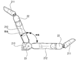
図3に示すとおり、各指部21は、第1指リンク部211、第2指リンク部212、および基端部213を有している。そして、指部21の基端部213がベース部20に接続されている。ここで、基端部213は、図4において矢印で示すように、ベース部20に対して指部21の長手方向(図4において紙面に垂直な方向)の軸回りに回転可能に接続されている。また、指部21において、基端部213に第2指リンク部212の一端が接続されている。そして、この第2指リンク部212と基端部213との接続部に第2関節部23が形成されている。ベース部20の内部には、基端部213を回転駆動させるモータ、および、第2指リンク部212を基端部213に対して相対的に回転駆動させるモータが設けられている。このような構成により、基端部213が回転駆動され、それに伴って、図4において矢印で示す範囲で指部21全体が回転駆動される。また、図5に示すように、第2関節部23が屈曲および伸展可能に形成されている。
また、図3、図5、および図6に示すように、指部21においては、第2指リンク部212の他端に第1指リンク部211の一端が接続されている。そして、この第1指リンク部211と第2指リンク部212との接続部に第1関節部22が形成されている。第2指リンク部212の内部には、第1指リンク部211を第2指リンク部212に対して相対的に回転駆動させるモータが設けられている。このような構成により、図6に示すように、第1関節部22は屈曲および伸展可能に形成されている。
また、図3に示すように、本実施例では、指部21の第1指リンク部211の先端側に感圧センサ70が設けられている。感圧センサ70は、第1指リンク部211の先端部に作用する外力(圧力)を検出するセンサである。
(台座部)
次に、台座部4に内蔵された、アーム制御装置42およびハンド制御装置43の構成について図7に基づいて説明する。アーム制御装置42は把持システム1のアーム機構3を制御するための制御装置である。ハンド制御装置43は把持システム1のハンド機構2を制御するための制御装置である。図7は、アーム制御装置42およびハンド制御装置43に含まれる各機能部を示すブロック図である。
次に、台座部4に内蔵された、アーム制御装置42およびハンド制御装置43の構成について図7に基づいて説明する。アーム制御装置42は把持システム1のアーム機構3を制御するための制御装置である。ハンド制御装置43は把持システム1のハンド機構2を制御するための制御装置である。図7は、アーム制御装置42およびハンド制御装置43に含まれる各機能部を示すブロック図である。
アーム制御装置42は、アーム機構3の各関節部に設けられたモータを駆動するための駆動信号を生成する複数のドライバを含み、各ドライバからの駆動信号が対応する各モータに供給されるように構成される。また、アーム制御装置42は、演算処理装置及びメモリを有するコンピュータを含んでいる。そして、アーム制御装置42は、機能部として、アーム制御部420およびモータ状態量取得部421を有している。これらの機能部は、アーム制御装置42に含まれるコンピュータにおいて所定の制御プログラムが実行されることで形成される。
アーム制御部420は、ハンド制御装置43が有する機能部である後述の対象物情報取得部430によって取得された対象物情報に基づいて各ドライバから駆動信号を供給することで、アーム機構3の各関節部30a、30b、30c、30d、30e、30fに設けられたモータを制御する。そして、アーム制御部420は、各モータを制御することでアーム機構3を動かし、それによって、ハンド機構2の位置を所望の位置(ハンド機構2によって対象物10を把持することが可能な位置)に移動させる。また、アーム機構3の各関節部30a、30b、30c、30d、30e、30fに設けられたモータには、それぞれの回転状態に関する状態量(モータの回転軸の回転位置や回転速度等)を検出するエンコーダ(図示略)が設けられている。そして、各モータのエンコーダによって検出された各モータの状態量が、アーム制御装置42のモータ状態量取得部421に入力される。そして、アーム制御部420は、モータ状態量取得部421に入力された各モータの状態量に基づいて、ハンド機構2が所望の位置に移動するように各モータをサーボ制御する。
また、ハンド制御装置43は、ハンド機構2に設けられた各モータを駆動するための駆動信号を生成する複数のドライバを含み、各ドライバからの駆動信号が対応する各モータに供給されるように構成される。また、ハンド制御装置43は、演算処理装置及びメモリを有するコンピュータを含んでいる。そして、ハンド制御装置43は、機能部として、対象物情報取得部430、ハンド制御部431、モータ状態量取得部432、およびセンサ情報取得部433を有している。これらの機能部は、ハンド制御装置43に含まれるコンピュータにおいて所定の制御プログラムが実行されることで形成される。
対象物情報取得部430は、ハンド機構2よって把持すべき対象物に関する情報である対象物情報を取得する。ここで、対象物情報には、対象物の種類、形状、寸法、およびその位置に関する情報、並びに、対象物周囲の環境情報(対象物の周囲に存在する該対象物以外の物に関する情報であり、例えば、対象物が収容されている容器の形状や当該容器における対象物の並びに関する情報)等が含まれる。この対象物情報取得部430は、ユーザーによって入力された対象物情報を取得してもよい。また、対象物を含む画像を撮像する視覚センサが設けられている場合、対象物情報取得部430は、該視覚センサによって撮像された画像から対象物情報を取得してもよい。
また、ハンド制御部431は、対象物情報取得部430によって取得された対象物情報に基づいて各ドライバから駆動信号を供給することで、ハンド機構2の各指部21を駆動させる各モータを制御する。これにより、ハンド機構2の複数の指部21によって対象物10が把持される。また、ハンド機構2の各モータには、それぞれの回転状態に関する状態量(モータの回転軸の回転位置や回転速度等)を検出するエンコーダ(図示略)が設けられている。そして、各モータのエンコーダによって検出された各モータの状態量が、ハンド制御装置43のモータ状態量取得部432に入力される。そして、ハンド制御部431は、モータ状態量取得部432に入力された各モータの状態量に基づいて、複数の指部21によって対象物を把持するように、各指部21における各モータをサーボ制御する。
さらに、ハンド制御装置43はセンサ情報取得部433を有している。センサ情報取得部433には、ハンド機構2の各指部21の第1指リンク部211に設けられた感圧センサ70の検出値が入力される。そして、ハンド制御部431は、各感圧センサ70によって、各指部21の対象物への接触が検知された場合に、その検知信号に基づいて各指部21における各モータを制御することもできる。
なお、図7では、把持システムに含まれる制御装置として、アーム制御装置42とハンド制御装置43とが区別して示されているが、別法として、各機能部が、両装置が一体化された一の制御装置内に形成される構成を採用することもできる。また、把持システムに含まれる制御装置が、アーム制御装置42とハンド制御装置43とに区別される場合でも、図7に示す各機能部は、技術的な齟齬が生じない限りにおいて実質的に何れかの制御装置内に形成されればよく、必要に応じてアーム制御装置42とハンド制御装置43との間で適切な情報の授受を行うことができる。また、アーム制御装置42またはハンド制御装置43における各機能部のうちの一部が、アーム制御装置42およびハンド制御装置43とは別体の制御装置内に形成される構成を採用することもできる。
(把持対象物)
本実施例に係る把持システム1においては、把持の対象物10が、流体(気体または液体)が封入された袋状対象物である場合がある。気体が封入された袋状対象物10としては、ポテトチップスやポップコーンなどのお菓子が入った袋を例示することができる。また、液体が封入された袋状対象物10としては、漬物が入った袋や、液体洗剤が入った袋を例示することができる。このような、流体が封入された袋状対象物10をハンド機構2によって把持しようとすると、把持に使用する指部21(以下、把持用指部)と称する場合もある。)によって押圧された際に該袋状対象物10の形状が変化し易い。把持用指部の押圧によって袋状対象物10が変形してしまうと、該把持用指部が袋状対象物10から受ける反力が小さくなる。その結果、把持用指部と袋状対象物との間で十分な摩擦力を確保することが困難となると、袋状対象物10が把持用指部によって挟みこまれた状態が維持され難い場合がある。
本実施例に係る把持システム1においては、把持の対象物10が、流体(気体または液体)が封入された袋状対象物である場合がある。気体が封入された袋状対象物10としては、ポテトチップスやポップコーンなどのお菓子が入った袋を例示することができる。また、液体が封入された袋状対象物10としては、漬物が入った袋や、液体洗剤が入った袋を例示することができる。このような、流体が封入された袋状対象物10をハンド機構2によって把持しようとすると、把持に使用する指部21(以下、把持用指部)と称する場合もある。)によって押圧された際に該袋状対象物10の形状が変化し易い。把持用指部の押圧によって袋状対象物10が変形してしまうと、該把持用指部が袋状対象物10から受ける反力が小さくなる。その結果、把持用指部と袋状対象物との間で十分な摩擦力を確保することが困難となると、袋状対象物10が把持用指部によって挟みこまれた状態が維持され難い場合がある。
(押し込み動作)
そこで、本実施例では、流体が封入された袋状対象物10をハンド機構2によって把持する場合、把持用指部によって袋状対象物を挟み込むための動作である把持動作を実行する前に、ハンド機構2の指部21の先端部を袋状対象物10に接触させて該袋状対象物10に押し込む押し込み動作を実行する。このような押し込み動作を行うと、袋状対象物10が変形するため、該袋状対象物10の内圧を高めることができる。そして、押し込み動作を実行することで袋状対象物10の内圧が十分に上昇している状態であれば、把持動作を行った際に、該袋状対象物10が把持用指部によって押圧されても、その形状が変化し難くなる。その結果、把持用指部に対し袋状対象物10から十分な反力が作用するようになる。そのため、把持用指部と袋状対象物10との間で把持に十分な摩擦力を確保することが可能となる。
そこで、本実施例では、流体が封入された袋状対象物10をハンド機構2によって把持する場合、把持用指部によって袋状対象物を挟み込むための動作である把持動作を実行する前に、ハンド機構2の指部21の先端部を袋状対象物10に接触させて該袋状対象物10に押し込む押し込み動作を実行する。このような押し込み動作を行うと、袋状対象物10が変形するため、該袋状対象物10の内圧を高めることができる。そして、押し込み動作を実行することで袋状対象物10の内圧が十分に上昇している状態であれば、把持動作を行った際に、該袋状対象物10が把持用指部によって押圧されても、その形状が変化し難くなる。その結果、把持用指部に対し袋状対象物10から十分な反力が作用するようになる。そのため、把持用指部と袋状対象物10との間で把持に十分な摩擦力を確保することが可能となる。
以下、本実施例に係る押し込み動作の詳細について図8および図9に基づいて説明する。ここでは、ハンド機構2における4本の指部21のうち2本の指部21A、21Cを押し込み用指部として押し込み動作を実行する。なお、押し込み動作は、アーム制御装置42のアーム制御部420によってアーム機構3が制御されるとともに、ハンド制御装置43のハンド制御部431によってハンド機構2が制御されることで実現される。図8は、指部21A、21Cを使用して押し込み動作を実行する際のハンド機構2の形態を示した図である。ただし、図8では指部21Bの図示は便宜上省略している。図8中の白抜き矢印は袋状対象物10に対する押し込み方向を図示している。アーム制御部420はアーム機構3を制御して、ハンド機構2を指部21A、21Cによる押し込み動作に好適な位置に移動させる。すなわち、アーム制御部420は、ハンド機構2を押し込み方向に移動させることで指部21A、21Cの先端部を袋状対象物10に接触させることが可能な位置に該ハンド機構2を移動させる。さらに、ハンド制御部431は、押し込み用指部21A、21Cの先端部を袋状対象物10に接触させることができるように、各指部21の形態を制御する。その際の、押し込み用指部21A、21C同士の先端部の間の距離dを所定の距離以上あけた状態とする。
また、本実施例では、図8に示すように、各押し込み用指部21A、21Cの先端部の押し込み方向に垂直な平面に対する高さhを同一とする。これによって、押し込み用指部21A、21Cそれぞれの先端部を袋状対象物10に対して接触させ易くすることができる。また、押し込み用指部21A、21Cそれぞれの先端部を袋状対象物10に対して均等に押し込むことができる。ただし、各押し込み用指部21A、21Cの先端部の押し込み方向に垂直な平面に対する高さは必ずしも同一でなくてもよい。つまり、押し込み動作において、各押し込み用指部21A、21Bの先端部を袋状対象物10に接触させることができるように、それぞれの先端部が配置されていればよい。
また、押し込み動作に使用しない指部21B、21Dの先端部の押し込み方向に垂直な平面に対する高さは、高さhより高くする。各指部21の先端部をこのように配置することによって、押し込み動作において、押し込み用指部21A、21Cの先端部のみを袋状対象物10に接触させることができる。ただし、押し込み用指部21A、21Cの先端部のみを袋状対象物10に接触させることができる配置であれば、押し込み動作に使用しない指部21Bと指部21Dの先端部の押し込み方向に垂直な平面に対する高さが押し込み用指部21A、21Cの当該高さより低くてもよい。
上記のような押し込み動作のための形態を実現させるための制御は、対象物情報取得部430によって取得された袋状対象物10の対象物の種類、形状、寸法、その位置に関する情報などを含む対象物情報に基づいて実行される。なお、袋状対象物10における押し込み用指部の押し込み位置や、押し込み用指部の押し込み方向はユーザーが適宜決定することもできる。また、これらの押し込み位置や押し込み方向を、対象物情報取得部430によって取得された対象物情報に基づいてハンド制御部431やアーム制御部420が決定してもよい。また、押し込み用指部は指部21A、21Cに限るわけではなく、他の指部21の組み合わせでもよい。図8に示すようなハンド機構2の位置および形態を実現するための制御が完了した後、アーム制御部420はアーム機構3を制御して、図8記載の白抜き矢印の方向にハンド機構2を移動させることによって、押し込み動作を開始する。
図9は、押し込み用指部21Aおよび21Cによって、袋状対象物10に対して押し込み動作を実行している際のハンド機構2および袋状対象物10の様子を示した図である。なお、図9中の白抜き矢印は袋状対象物10に対する押し込み方向を図示している。押し込み動作が開始されると、先ず、押し込み用指部21A、21Cの先端部が袋状対象物10に接触する。その後、さらに、図9中の白抜き矢印の方向への押し込み動作が継続される。これにより、袋状対象物10が変形し、それに伴い、該袋状対象物10の内圧が高くなる。そして、押し込み動作における袋状対象物10への押し込み用指部21A、21Cの押し込み量が増加するにつれて、該袋状対象物10の内圧が上昇する。ここで、押し込み量は、押し込み動作開始後に袋状対象物10に押し込み用指部21A、21Cの先端部が接触した位置からの、押し込み方向(図9中の白抜き矢印の方向)における該押し込み用指部21A、21Cの先端部の変位量として定義できる。図9中の破線は、押し込み用指部21A、21Cが袋状対象物10に接触した時の袋状対象物10を図示している。図9では、押し込み動作を実行している際の押し込み用指部21A、21Cの押し込み量をLと記載している。
このとき、押し込み用指部21A、21Cの先端部に設置されている感圧センサ70は、袋状対象物10から受ける圧力を検知する。そのため、袋状対象物10への押し込み用指部21A、21Cの押し込み量の増加に伴い該袋状対象物10の内圧が上昇すると、各押し込み用指部21A、21Cの先端部に設置されている感圧センサ70によって検知される圧力も上昇する。センサ情報取得部433は、各押し込み用指部21A、21Cに設けられた感圧センサ70によって検知された圧力をそれぞれ独立した値として取得する。そして、センサ情報取得部433によって取得された、各押し込み用指部21A、21Cに設けられた感圧センサ70によって検知された圧力のいずれかが所定の圧力以上となったときに、アーム制御部420が、ハンド機構2を図9中の白抜き矢印の方向に移動させるためのアーム機構3の駆動を停止する。これによって、袋状対象物10に対する押し込み動作を停止する。ここで、所定の圧力は、後述の把持動作において、把持に使用される把持用指部と袋状対象物10との間に、該対象物の把持を実現するために十分な摩擦力を確保することができる圧力である。所定の圧力は、ユーザーが実験等に基づき適宜決定することもできる。また、対象物情報取得部430によって取得された対象物情報に基づいてセンサ情報取得部433が決定してもよい。なお、押し込み動作中においては、ハンド制御部431が、各押し込み用指部21A、21Cの先端部のハンド機構2での位置を変えないように、各押し込み用指部21A、21Cにおける各モータをサーボ制御している。また、本実施例では、感圧センサ70はハンド機構2の全ての指部21に設置されている。しかしながら、押し込み動作を実現させるためには、感圧センサ70は、少なくとも、押し込み用指部となる指部(本実施例では、指部21Aおよび指部21C)の先端部に設置されていればよい。押し込み用指部の先端部に感圧センサ70が設置されていれば、袋状対象物10の内圧が、把持動作が可能な程度まで上昇しているか否かを判断することができる。
(把持動作)
次に、本実施例に係る把持動作の詳細について図10に基づいて説明する。図10は、押し込み動作において押し込み用指部として使用していた指部21A、21Cを把持用指部として把持動作を実行した際のハンド機構2および袋状対象物10の様子を示した図である。本実施例では、押し込み動作の停止後に把持動作が実行される。このとき、押し込み動作の停止時における押し込み用指部21A、21Cが袋状対象物10に押し込まれた状態を維持しつつ把持動作が実行される。より詳細には、ハンド制御部431が、図10に示すように、押し込み用指部として使用していた指部21A、21Cを把持用指部とし、該把持用指部21A、21Cを袋状対象物10に押し込んだ状態を維持しつつ、それぞれの第1関節部22A、22Cを屈曲させる(図10においては、矢印が、各指部21A、21Cの第1関節部22A、22Cの屈曲の方向を示している。)。このことによって、把持用指部21A、21C同士の先端部間の距離を短くすることで、該把持用指部21A、21Cによって袋状対象物10を挟み込む動作である把持動作を実現する。なお、このとき、ハンド制御部431は、把持用指部21A、21Cそれぞれの第2関節部23A、23Cを屈曲させることで把持動作を実現してもよい。ここで、把持用指部21A、21Cそれぞれの第1関節部22A、22Cおよび/または第2関節部23A、23Cを屈曲させても、押し込み動作停止時点の各指部21A、21Cの先端部の袋状対象物10に対する押し込み量(図9における押し込み量L)は維持されている。そのため、把持用指部21A、21Cには袋状対象物10から十分な反力が作用している。よって、把持用指部21A、21Cと袋状対象物10との間において、該袋状対象物10の把持を実現するのに十分な摩擦力が発生する。したがって、袋状対象物10が把持用指部21A、21Cによって挟みこまれた状態が維持されやすくなる。その結果、ハンド機構2によって袋状対象物10を安定して把持することが可能となる。
次に、本実施例に係る把持動作の詳細について図10に基づいて説明する。図10は、押し込み動作において押し込み用指部として使用していた指部21A、21Cを把持用指部として把持動作を実行した際のハンド機構2および袋状対象物10の様子を示した図である。本実施例では、押し込み動作の停止後に把持動作が実行される。このとき、押し込み動作の停止時における押し込み用指部21A、21Cが袋状対象物10に押し込まれた状態を維持しつつ把持動作が実行される。より詳細には、ハンド制御部431が、図10に示すように、押し込み用指部として使用していた指部21A、21Cを把持用指部とし、該把持用指部21A、21Cを袋状対象物10に押し込んだ状態を維持しつつ、それぞれの第1関節部22A、22Cを屈曲させる(図10においては、矢印が、各指部21A、21Cの第1関節部22A、22Cの屈曲の方向を示している。)。このことによって、把持用指部21A、21C同士の先端部間の距離を短くすることで、該把持用指部21A、21Cによって袋状対象物10を挟み込む動作である把持動作を実現する。なお、このとき、ハンド制御部431は、把持用指部21A、21Cそれぞれの第2関節部23A、23Cを屈曲させることで把持動作を実現してもよい。ここで、把持用指部21A、21Cそれぞれの第1関節部22A、22Cおよび/または第2関節部23A、23Cを屈曲させても、押し込み動作停止時点の各指部21A、21Cの先端部の袋状対象物10に対する押し込み量(図9における押し込み量L)は維持されている。そのため、把持用指部21A、21Cには袋状対象物10から十分な反力が作用している。よって、把持用指部21A、21Cと袋状対象物10との間において、該袋状対象物10の把持を実現するのに十分な摩擦力が発生する。したがって、袋状対象物10が把持用指部21A、21Cによって挟みこまれた状態が維持されやすくなる。その結果、ハンド機構2によって袋状対象物10を安定して把持することが可能となる。
<制御フロー>
次に、本実施例に係る、袋状対象物10の把持を実行する際の把持システムの制御フローについて図11に示すフローチャートに基づいて説明する。本制御フローは、アーム制御装置42のアーム制御部420及びハンド制御装置43のハンド制御部431において所定の制御プログラムが実行されることで実現される。
次に、本実施例に係る、袋状対象物10の把持を実行する際の把持システムの制御フローについて図11に示すフローチャートに基づいて説明する。本制御フローは、アーム制御装置42のアーム制御部420及びハンド制御装置43のハンド制御部431において所定の制御プログラムが実行されることで実現される。
本フローでは、まずS101において、対象物情報取得部430によって取得された袋状対象物10についての対象物情報に基づいて、押し込み動作を実行するためのハンド機構2の位置および形態が決定される。次に、S102において、ハンド機構2の位置および形態が、S101で決定された位置および形態に制御される。これにより、本実施例では、図8で示したような、押し込み動作を実行するためのハンド機構2の位置および形態が実現される。
次に、S103において、押し込み動作が開始される。すなわち、押し込み動作用の形態となっているハンド機構2の押し込み方向(図8および図9における白抜き矢印の方向)への移動が開始される。上述したように、押し込み動作が行われると、ハンド機構2の押し込み用指部21A、21Cの先端部が、袋状対象物10に接触し、その後、該袋状対象物10に押し込まれる。次に、S104において、センサ情報取得部433によって取得される、各押し込み用指部21A、21Cに設けられた感圧センサ70によって検知された圧力P1、P2のいずれかが所定の圧力Pn以上となったか否かが判別される。S104において否定の判定が行われると、該S104の処理が再度実行される。この場合、押し込み動作が継続される。すなわち、ハンド機構2の押し込み方向への移動が継続される。そのため、ハンド機構2の押し込み用指部21A、21Cの先端部の袋状対象物10に対する押し込み量が増加する。
一方で、S104で肯定の判定が行われると、次に、S105において、押し込み動作が停止される。すなわち、ハンド機構2の押し込み方向への移動が停止される。その後、ハンド機構2の位置は、押し込み動作が停止された時点の位置に維持される。S105において押し込み動作が停止されると、S106の処理が実行される。S106では、把持用指部21A、21Cによる把持動作が開始される。これにより、ハンド機構2の指部21A、21Cの先端部が袋状対象物10に押し込まれた状態が維持されつつ、該指部21A、21Cによって該袋状対象物10が挟み込まれる。
なお、本実施例では押し込み用指部21A、21Cによる押し込み動作の停止後に把持用指部21A、21Cによる把持動作を開始している。ただし、押し込み動作により、押し込み用指部21A、21Cに設けられた感圧センサ70によって検知された圧力のいずれかが所定の圧力以上となったときに、押し込み動作を継続しながら把持動作を開始してもよい。
(変形例1)
上記実施例では、押し込み用指部として2本の指部21A、21Cを使用した。しかしながら、押し込み用指部は2本に限られるものではない。つまり、ハンド機構2における4本の指部21または3本の指部21を押し込み用指部として使用してもよい。この場合でも、上記実施例と同様に、各押し込み用指部同士の先端部間は所定の間隔をあけて押し込み動作を実行する。なお、ハンド機構2における4本の指部21または3本の指部21を押し込み用指部として使用する場合でも、少なくとも押し込み用指部として使用される各指部21の先端部に感圧センサ70が設置される。また、ハンド機構2における4本の指部21または3本の指部21を押し込み用指部として使用する場合でも、押し込み用指部として使用した各指部21を把持用指部としても使用して把持動作を行うことができる。なお、押し込み用指部の数はユーザーが適宜決定することができる。また、押し込み用指部の数は、対象物情報取得部430によって取得された対象物情報に基づいて、ハンド制御部431が決定してもよい。
上記実施例では、押し込み用指部として2本の指部21A、21Cを使用した。しかしながら、押し込み用指部は2本に限られるものではない。つまり、ハンド機構2における4本の指部21または3本の指部21を押し込み用指部として使用してもよい。この場合でも、上記実施例と同様に、各押し込み用指部同士の先端部間は所定の間隔をあけて押し込み動作を実行する。なお、ハンド機構2における4本の指部21または3本の指部21を押し込み用指部として使用する場合でも、少なくとも押し込み用指部として使用される各指部21の先端部に感圧センサ70が設置される。また、ハンド機構2における4本の指部21または3本の指部21を押し込み用指部として使用する場合でも、押し込み用指部として使用した各指部21を把持用指部としても使用して把持動作を行うことができる。なお、押し込み用指部の数はユーザーが適宜決定することができる。また、押し込み用指部の数は、対象物情報取得部430によって取得された対象物情報に基づいて、ハンド制御部431が決定してもよい。
(変形例2)
また、ハンド機構2における少なくとも2本の指部21を把持動作に使用すれば袋状対象物10を把持することができる。そのため、必ずしも、押し込み用指部として使用した全ての指部21を把持用指部として使用する必要はない。つまり、ハンド機構2における3本の指部21を押し込み用指部として使用した場合に、該3本の押し込み用指部のうちの2本を把持用指部として使用して把持動作を行ってもよい。また、ハンド機構2における4本の指部21を押し込み用指部として使用した場合、該4本の押し込み用指部のうちの2本または3本を把持用指部として使用して把持動作を行ってもよい。ただし、これらの場合でも、複数の押し込み用指部の先端部を袋状対象物10に押し込んだ状態を維持しつつ把持用指部による把持動作を実行する。また、押し込み用指部として使用した指部21とは異なる指部21を把持用指部として使用してもよい。
また、ハンド機構2における少なくとも2本の指部21を把持動作に使用すれば袋状対象物10を把持することができる。そのため、必ずしも、押し込み用指部として使用した全ての指部21を把持用指部として使用する必要はない。つまり、ハンド機構2における3本の指部21を押し込み用指部として使用した場合に、該3本の押し込み用指部のうちの2本を把持用指部として使用して把持動作を行ってもよい。また、ハンド機構2における4本の指部21を押し込み用指部として使用した場合、該4本の押し込み用指部のうちの2本または3本を把持用指部として使用して把持動作を行ってもよい。ただし、これらの場合でも、複数の押し込み用指部の先端部を袋状対象物10に押し込んだ状態を維持しつつ把持用指部による把持動作を実行する。また、押し込み用指部として使用した指部21とは異なる指部21を把持用指部として使用してもよい。
<実施例2>
本実施例に係る把持システムの概略構成は上記実施例1と同様である。本実施例では、ハンド機構2における4本の指部21のうちの一部を押し込み用指部として使用して押し込み動作を実行する。そして、ハンド機構2における4本の指部21のうち、押し込み用指部として使用されなかった指部21を用いて把持動作を実行する。以下においては、ハンド機構2の指部21のうち、押し込み用指部として2本の指部21A、21Cを使用し、且つ、把持用指部として他の2本の指部21B、21Dを使用する例について、図12に基づいて説明する。図12は、本実施例に係る押し込み動作および把持動作について説明するための図である。
本実施例に係る把持システムの概略構成は上記実施例1と同様である。本実施例では、ハンド機構2における4本の指部21のうちの一部を押し込み用指部として使用して押し込み動作を実行する。そして、ハンド機構2における4本の指部21のうち、押し込み用指部として使用されなかった指部21を用いて把持動作を実行する。以下においては、ハンド機構2の指部21のうち、押し込み用指部として2本の指部21A、21Cを使用し、且つ、把持用指部として他の2本の指部21B、21Dを使用する例について、図12に基づいて説明する。図12は、本実施例に係る押し込み動作および把持動作について説明するための図である。
本実施例では、上記実施例1において図8および図9に示した場合と同様、ハンド機構2における指部21A、21Cを押し込み用指部として使用して押し込み動作が実行される。なお、本実施例においても、押し込み用指部21A、21C同士の先端部の間の距離は所定の距離以上空けた状態となっている。また、図12に示すように、本実施例では、押し込み用指部として使用しない指部21B、21Dは、押し込み動作において袋状対象物10に接触しないように、その形態が制御されている。そして、各押し込み用指部21A、21Cに設けられた感圧センサ70によって検知された圧力のいずれかが所定の圧力以上となったときに押し込み動作が停止される。
押し込み動作が停止されると、押し込み用指部として使用されていない指部21B、21Dを把持用指部として把持動作が実行される。このとき、押し込み動作の停止時における押し込み用指部21A、21Cが袋状対象物10に押し込まれた状態を維持しつつ把持動作が実行される。なお、把持動作は、ハンド制御部431が、把持用指部21B、21Dによって袋状対象物10を挟み込む方向に、各把持用指部21B、21Dそれぞれの関節部を駆動させることで実現される(図12においては、矢印が、各把持用指部21B、21Dの関節部の駆動方向を示している)。なお、把持動作中においては、ハンド制御部431が、押し込み用指部21A、21Cの位置を変えないように、押し込み用指部21A、21Cそれぞれにおける各モータをサーボ制御している。
上記のように、本実施例においては、押し込み用指部21A、21Cの先端部が袋状対象物10に押し込まれた状態が維持されつつ、把持用指部21B、21Dによって該袋状対象物10が挟み込まれる。従って、把持用指部21B、21Dには袋状対象物10から十分な反力が作用している。よって、把持用指部21B、21Dと袋状対象物10との間において、該袋状対象物10の把持を実現するに十分な摩擦力が発生する。したがって、袋状対象物10が把持用指部21B、21Dによって挟み込まれた状態が維持されやすくなる。その結果、ハンド機構2によって袋状対象物10を安定して把持することが可能となる。
ただし、上記実施例2のように、押し込み用指部21A、21Cとは異なる把持用指部21B、21Dによって把持動作を行う場合、押し込み動作を停止した後に、把持用指部21B、21Dを袋状対象物10に接触させ、その後、該把持用指部21B、21Dによって該袋状対象物10を挟み込むことになる。これに対し、上記実施例1のように、押し込み用指部を把持用指部としても使用して把持動作を行う場合、押し込み動作を停止した時点で、すでに把持用指部が袋状対象物10に接触した状態となっている。そのため、押し込み動作を停止した直後に、把持用指部によって袋状対象物を挟み込むことができる。したがって、上記実施例1のように、押し込み用指部を把持用指部としても使用して把持動作を行う場合、上記実施例2のように、押し込み用指部とは異なる把持用指部によって把持動作を行う場合に比べて、袋状対象物10の把持に係るタクトタイムを短縮することができる。
なお、本実施例は押し込み用指部21A、21Cによる押し込み動作の停止後に把持用指部21B、21Dによる把持動作を開始している。ただし、押し込み動作により、押し込み用指部21A、21Cに設けられた感圧センサ70によって検知された圧力のいずれかが所定の圧力以上となったときに、押し込み動作を継続しながら把持動作を開始してもよい。また、ハンド機構2において、押し込み用指部として使用している指部と、押し込み用指部以外の指部とを使用して、把持動作を実行することも可能である。ただし、この場合でも、押し込み用指部を袋状対象物10に押し込んだ状態を維持しつつ、把持動作を実行する。
(変形例)
ハンド機構2における1本の指部21のみを押し込み用指部として使用して押し込み動作を行うこともできる。この場合、1本の押し込み用指部による押し込み動作の開始後に、該押し込み用指部に設置された感圧センサ70によって検知された圧力が所定の圧力以上となったときに、該押し込み動作が停止される。その後、1本の押し込み用指部が袋状対象物10に押し込まれた状態を維持しつつ、把持用指部による把持動作が実行される。
ハンド機構2における1本の指部21のみを押し込み用指部として使用して押し込み動作を行うこともできる。この場合、1本の押し込み用指部による押し込み動作の開始後に、該押し込み用指部に設置された感圧センサ70によって検知された圧力が所定の圧力以上となったときに、該押し込み動作が停止される。その後、1本の押し込み用指部が袋状対象物10に押し込まれた状態を維持しつつ、把持用指部による把持動作が実行される。
ただし、押し込み用指部が1本のみの場合、押し込み用指部が複数の場合に比べて、押し込み動作を実行したときの袋状対象物10に対する押し込み用指部の押し込み量が大きくなってしまう。換言すれば、図8、9または図12に例示したように、少なくとも2本の指部を押し込み用指部として使用し、押し込み用指部同士の先端部間の距離を所定の距離以上空けた状態で押し込み動作を行う場合、1本の押し込み用指部によって押し込み動作を行う場合に比べて、袋状対象物10の内圧を同程度高めるときの該袋状対象物10に対する押し込み用指部の押し込み量をより小さくすることができる。すなわち、押し込み動作停止時における袋状対象物10に対する押し込み用指部の押し込み量をより小さくすることができる。このように袋状対象物に対する押し込み用指部の押し込み量が小さくなることで、押し込み動作に伴って該袋状対象物10の内容物が破損してしまうことを抑制することができる。また、袋状対象物10に対する押し込み用指部の押し込み量が小さくなることで、押し込み動作開始から把持動作開始までにかかる時間を短縮することができる。その結果、袋状対象物の把持に係るタクトタイムを短縮することができる。
1・・・把持システム、2・・・ハンド機構、20・・・ベース部、21・・・指部、22・・・第1関節部、23・・・第2関節部、211・・・第1指リンク部、212・・・第2指リンク部、213・・・基端部、3・・・アーム機構、30a・・・第1関節部、30b・・・第2関節部、30c・・・第3関節部、30d・・・第4関節部、30e・・・第5関節部、30f・・・第6関節部、31・・・第1アームリンク部、32・・・第2アームリンク部、33・・・第3アームリンク部、34・・・第4アームリンク部、35・・・第5アームリンク部、36・・・接続部材、4・・・台座部、42・・・アーム制御装置、420・・・アーム制御部、421・・・モータ状態量取得部、43・・・ハンド制御装置、430・・・対象物情報取得部、431・・・ハンド制御部、432・・・モータ状態量取得部、433・・・センサ情報取得部、70・・・感圧センサ
Claims (5)
- 複数の指部によって対象物を把持するハンド機構と、
前記対象物を把持する際に前記ハンド機構を制御する制御装置と、を備える把持システムであって、
前記対象物が、その内部に流体が封入された袋状対象物である場合に、前記ハンド機構の前記複数の指部のうち少なくとも1本の指部を押し込み用指部とし、
前記ハンド機構における前記押し込み用指部となる指部の先端部に圧力検知部が設けられており、
前記対象物が前記袋状対象物である場合に、前記制御装置は、前記ハンド機構の前記押し込み用指部の先端部を前記袋状対象物に接触させて前記袋状対象物に押し込み、その後、1本の前記押し込み用指部に設けられた前記圧力検知部によって検知された圧力、または、各押し込み用指部に設けられた前記圧力検知部によって検知された圧力のいずれかが所定の圧力以上となってから、前記複数の指部のうち少なくとも2本の指部によって前記袋状対象物を挟み込む動作である把持動作を、前記押し込み用指部を前記袋状対象物に押し込んだ状態で実行する把持システム。 - 前記押し込み用指部が少なくとも2本の指部であって、前記制御装置が、前記押し込み用指部同士の先端部間の距離を所定の距離以上空けた状態で、各押し込み用指部の先端部を前記袋状対象物に接触させて前記袋状対象物に押し込む請求項1に記載の把持システム。
- 前記制御装置が、前記押し込み用指部を前記袋状対象物に押し込んだ状態を維持しつつ、前記押し込み用指部を用いて前記把持動作を実行する請求項1または2に記載の把持システム。
- 前記押し込み用指部が少なくとも2本の指部である場合に、前記制御装置が、前記押し込み用指部の押し込み方向に垂直な平面に対する前記押し込み用指部の先端部の高さを同一にした状態で、各押し込み用指部の先端部を前記袋状対象物に接触させて前記袋状対象物に押し込む請求項1から3のいずれかに記載の把持システム。
- 複数の指部を備えるハンド機構によって対象物を把持する把持方法において、
前記対象物が、その内部に流体が封入された袋状対象物である場合に、前記ハンド機構の前記複数の指部のうち少なくとも1本の指部を押し込み用指部とし、
前記ハンド機構において、前記押し込み用指部となる指部の先端部に圧力検知部が設けられており、
前記対象物が前記袋状対象物である場合に、前記押し込み用指部の先端部を前記袋状対象物に接触させて前記袋状対象物に押し込むステップと、
1本の前記押し込み用指部に設けられた前記圧力検知部によって検知された圧力、または、各押し込み用指部に設けられた前記圧力検知部によって検知された圧力のいずれかが所定の圧力以上となってから、前記複数の指部のうち少なくとも2本の指部によって前記袋状対象物を挟み込む動作である把持動作を、前記押し込み用指部を前記袋状対象物に押し込んだ状態で実行するステップと、を有する把持方法。
Priority Applications (3)
| Application Number | Priority Date | Filing Date | Title |
|---|---|---|---|
| DE112020001274.3T DE112020001274B4 (de) | 2019-03-15 | 2020-03-16 | Greifsystem und Greifverfahren |
| US17/437,910 US11400589B2 (en) | 2019-03-15 | 2020-03-16 | Gripping system and gripping method |
| CN202080021129.4A CN113573858B (zh) | 2019-03-15 | 2020-03-16 | 把持系统以及把持方法 |
Applications Claiming Priority (2)
| Application Number | Priority Date | Filing Date | Title |
|---|---|---|---|
| JP2019048266A JP6829738B2 (ja) | 2019-03-15 | 2019-03-15 | 把持システムおよび把持方法 |
| JP2019-048266 | 2019-03-15 |
Publications (1)
| Publication Number | Publication Date |
|---|---|
| WO2020189619A1 true WO2020189619A1 (ja) | 2020-09-24 |
Family
ID=72431487
Family Applications (1)
| Application Number | Title | Priority Date | Filing Date |
|---|---|---|---|
| PCT/JP2020/011410 Ceased WO2020189619A1 (ja) | 2019-03-15 | 2020-03-16 | 把持システムおよび把持方法 |
Country Status (5)
| Country | Link |
|---|---|
| US (1) | US11400589B2 (ja) |
| JP (1) | JP6829738B2 (ja) |
| CN (1) | CN113573858B (ja) |
| DE (1) | DE112020001274B4 (ja) |
| WO (1) | WO2020189619A1 (ja) |
Citations (4)
| Publication number | Priority date | Publication date | Assignee | Title |
|---|---|---|---|---|
| JP2018192612A (ja) * | 2017-05-15 | 2018-12-06 | Thk株式会社 | ハンド機構、把持システム、および把持プログラム |
| JP2019034399A (ja) * | 2017-08-10 | 2019-03-07 | 株式会社京都製作所 | 把持装置 |
| WO2019044923A1 (ja) * | 2017-08-31 | 2019-03-07 | 川崎重工業株式会社 | 把持装置 |
| CN208775821U (zh) * | 2018-07-17 | 2019-04-23 | 青岛宏岩辅料印刷有限公司 | 一种包装袋导入机械手 |
Family Cites Families (18)
| Publication number | Priority date | Publication date | Assignee | Title |
|---|---|---|---|---|
| JP2007007859A (ja) * | 1996-08-05 | 2007-01-18 | Yaskawa Electric Corp | 多関節多指ハンドの物体把持方法 |
| JP2008528408A (ja) | 2005-02-05 | 2008-07-31 | プラース−リンク,アンドレアス | 汎用把持装置および保持装置 |
| JP5024227B2 (ja) | 2008-08-07 | 2012-09-12 | トヨタ自動車株式会社 | ロボットハンド |
| JP2010069584A (ja) * | 2008-09-19 | 2010-04-02 | Yaskawa Electric Corp | マニピュレータの制御装置および制御方法 |
| US8483880B2 (en) * | 2009-07-22 | 2013-07-09 | The Shadow Robot Company Limited | Robotic hand |
| US8662552B2 (en) | 2010-02-23 | 2014-03-04 | Massachusetts Institute Of Technology | Dexterous and compliant robotic finger |
| US8833826B2 (en) | 2011-03-21 | 2014-09-16 | Sri International | Mobile robotic manipulator system |
| US8991885B2 (en) | 2012-11-09 | 2015-03-31 | Irobot Corporation | Compliant underactuated grasper |
| US9004559B2 (en) | 2012-11-09 | 2015-04-14 | Irobot Corporation | Compliant underactuated grasper |
| CN104936749B (zh) | 2012-11-09 | 2017-11-17 | 艾罗伯特公司 | 顺从欠促动抓紧器 |
| US9089977B2 (en) * | 2012-11-09 | 2015-07-28 | Irobot Corporation | Compliant underactuated grasper |
| JP2015071207A (ja) * | 2013-10-03 | 2015-04-16 | 株式会社豊田自動織機 | ロボットハンドおよびその制御方法 |
| US9492928B2 (en) * | 2014-11-05 | 2016-11-15 | Toyota Motor Engineering & Manufacturing North America, Inc. | Interconnected phalanges for robotic gripping |
| CN104875205A (zh) * | 2015-05-13 | 2015-09-02 | 天津大宇包装制品有限公司 | 包装袋高速码垛机械手 |
| CN205257494U (zh) * | 2015-12-03 | 2016-05-25 | 浙江巨隆化肥有限公司 | 包装袋码垛机械手 |
| JP7097071B2 (ja) | 2016-01-20 | 2022-07-07 | ソフト ロボティクス, インコーポレイテッド | 散乱した握持環境、高加速移動、食品操作、および自動貯蔵および回収システムのためのソフトロボットグリッパ |
| CN206395485U (zh) * | 2016-09-14 | 2017-08-11 | 东莞市联匠机械零部件有限公司 | 物料抓取系统 |
| CN109176591B (zh) * | 2018-10-29 | 2021-06-25 | 太原理工大学 | 一种柔性自适应机械手 |
-
2019
- 2019-03-15 JP JP2019048266A patent/JP6829738B2/ja active Active
-
2020
- 2020-03-16 WO PCT/JP2020/011410 patent/WO2020189619A1/ja not_active Ceased
- 2020-03-16 US US17/437,910 patent/US11400589B2/en active Active
- 2020-03-16 CN CN202080021129.4A patent/CN113573858B/zh active Active
- 2020-03-16 DE DE112020001274.3T patent/DE112020001274B4/de active Active
Patent Citations (4)
| Publication number | Priority date | Publication date | Assignee | Title |
|---|---|---|---|---|
| JP2018192612A (ja) * | 2017-05-15 | 2018-12-06 | Thk株式会社 | ハンド機構、把持システム、および把持プログラム |
| JP2019034399A (ja) * | 2017-08-10 | 2019-03-07 | 株式会社京都製作所 | 把持装置 |
| WO2019044923A1 (ja) * | 2017-08-31 | 2019-03-07 | 川崎重工業株式会社 | 把持装置 |
| CN208775821U (zh) * | 2018-07-17 | 2019-04-23 | 青岛宏岩辅料印刷有限公司 | 一种包装袋导入机械手 |
Also Published As
| Publication number | Publication date |
|---|---|
| US11400589B2 (en) | 2022-08-02 |
| CN113573858A (zh) | 2021-10-29 |
| JP6829738B2 (ja) | 2021-02-10 |
| DE112020001274T5 (de) | 2021-12-02 |
| DE112020001274B4 (de) | 2023-03-30 |
| JP2020146819A (ja) | 2020-09-17 |
| US20220097229A1 (en) | 2022-03-31 |
| CN113573858B (zh) | 2022-07-01 |
Similar Documents
| Publication | Publication Date | Title |
|---|---|---|
| US11389951B2 (en) | Hand mechanism, gripping system, and non-transitory storage medium | |
| CN110997249B (zh) | 作业机器人和作业机器人的控制方法 | |
| US9242380B2 (en) | Robot, robot control apparatus, robot control method, and robot control program | |
| CN107717981B (zh) | 机械手臂的控制装置及其教导系统与方法 | |
| JP5505138B2 (ja) | ロボット装置およびロボット装置による把持方法 | |
| US20180111266A1 (en) | Control device, robot, and robot system | |
| TWI651175B (zh) | 機械手臂之控制裝置及其教導系統與方法 | |
| CN110914025B (zh) | 把持系统 | |
| US20200269445A1 (en) | Gripping system and gripping method | |
| JP6829738B2 (ja) | 把持システムおよび把持方法 | |
| JP6322948B2 (ja) | ロボット制御装置、ロボットシステム、ロボット、ロボット制御方法、及びプログラム | |
| JP2005144573A (ja) | ロボットハンドの把持力制御方法 | |
| JP2019042853A (ja) | 画像情報処理装置、把持システム、および画像情報処理方法 | |
| JP6958075B2 (ja) | ロボットシステムおよび制御方法 | |
| JP7178994B2 (ja) | 把持システム | |
| JP7069512B2 (ja) | 把持システムおよびその制御方法 | |
| WO2018212205A1 (ja) | ハンド機構、把持システム、および把持プログラム | |
| JP2024054618A (ja) | ロボットハンド、ロボットハンドの制御方法、ロボットシステム、ロボットシステムを用いた物品の製造方法、制御プログラム及び記録媒体 | |
| Matheswaran et al. | Control of Dual Robotic Arms via Marker-Less Hand Tracking | |
| WO2026052191A1 (en) | Manipulation of a workpiece using a robotic arm | |
| JP2018187755A (ja) | 制御装置、ロボットおよびロボットシステム |
Legal Events
| Date | Code | Title | Description |
|---|---|---|---|
| 121 | Ep: the epo has been informed by wipo that ep was designated in this application |
Ref document number: 20774234 Country of ref document: EP Kind code of ref document: A1 |
|
| 122 | Ep: pct application non-entry in european phase |
Ref document number: 20774234 Country of ref document: EP Kind code of ref document: A1 |