WO2020189468A1 - Ensemble cathéter - Google Patents
Ensemble cathéter Download PDFInfo
- Publication number
- WO2020189468A1 WO2020189468A1 PCT/JP2020/010685 JP2020010685W WO2020189468A1 WO 2020189468 A1 WO2020189468 A1 WO 2020189468A1 JP 2020010685 W JP2020010685 W JP 2020010685W WO 2020189468 A1 WO2020189468 A1 WO 2020189468A1
- Authority
- WO
- WIPO (PCT)
- Prior art keywords
- connector
- catheter
- catheter assembly
- opening member
- valve body
- Prior art date
Links
Images


Classifications
-
- A—HUMAN NECESSITIES
- A61—MEDICAL OR VETERINARY SCIENCE; HYGIENE
- A61M—DEVICES FOR INTRODUCING MEDIA INTO, OR ONTO, THE BODY; DEVICES FOR TRANSDUCING BODY MEDIA OR FOR TAKING MEDIA FROM THE BODY; DEVICES FOR PRODUCING OR ENDING SLEEP OR STUPOR
- A61M25/00—Catheters; Hollow probes
- A61M25/0097—Catheters; Hollow probes characterised by the hub
-
- A—HUMAN NECESSITIES
- A61—MEDICAL OR VETERINARY SCIENCE; HYGIENE
- A61M—DEVICES FOR INTRODUCING MEDIA INTO, OR ONTO, THE BODY; DEVICES FOR TRANSDUCING BODY MEDIA OR FOR TAKING MEDIA FROM THE BODY; DEVICES FOR PRODUCING OR ENDING SLEEP OR STUPOR
- A61M25/00—Catheters; Hollow probes
- A61M25/01—Introducing, guiding, advancing, emplacing or holding catheters
- A61M25/06—Body-piercing guide needles or the like
-
- A—HUMAN NECESSITIES
- A61—MEDICAL OR VETERINARY SCIENCE; HYGIENE
- A61M—DEVICES FOR INTRODUCING MEDIA INTO, OR ONTO, THE BODY; DEVICES FOR TRANSDUCING BODY MEDIA OR FOR TAKING MEDIA FROM THE BODY; DEVICES FOR PRODUCING OR ENDING SLEEP OR STUPOR
- A61M39/00—Tubes, tube connectors, tube couplings, valves, access sites or the like, specially adapted for medical use
- A61M39/02—Access sites
- A61M39/06—Haemostasis valves, i.e. gaskets sealing around a needle, catheter or the like, closing on removal thereof
- A61M2039/062—Haemostasis valves, i.e. gaskets sealing around a needle, catheter or the like, closing on removal thereof used with a catheter
-
- A—HUMAN NECESSITIES
- A61—MEDICAL OR VETERINARY SCIENCE; HYGIENE
- A61M—DEVICES FOR INTRODUCING MEDIA INTO, OR ONTO, THE BODY; DEVICES FOR TRANSDUCING BODY MEDIA OR FOR TAKING MEDIA FROM THE BODY; DEVICES FOR PRODUCING OR ENDING SLEEP OR STUPOR
- A61M25/00—Catheters; Hollow probes
- A61M25/01—Introducing, guiding, advancing, emplacing or holding catheters
- A61M25/06—Body-piercing guide needles or the like
- A61M25/0606—"Over-the-needle" catheter assemblies, e.g. I.V. catheters
-
- A—HUMAN NECESSITIES
- A61—MEDICAL OR VETERINARY SCIENCE; HYGIENE
- A61M—DEVICES FOR INTRODUCING MEDIA INTO, OR ONTO, THE BODY; DEVICES FOR TRANSDUCING BODY MEDIA OR FOR TAKING MEDIA FROM THE BODY; DEVICES FOR PRODUCING OR ENDING SLEEP OR STUPOR
- A61M39/00—Tubes, tube connectors, tube couplings, valves, access sites or the like, specially adapted for medical use
- A61M39/22—Valves or arrangement of valves
- A61M39/26—Valves closing automatically on disconnecting the line and opening on reconnection thereof
Definitions
- the present invention relates to a catheter assembly including a valve body that prevents blood from flowing out and an opening member that opens the valve body.
- the catheter assembly that functions as an indwelling needle.
- the catheter assembly (catheter assembly) disclosed in Japanese Patent Application Laid-Open No. 2014-528807 includes a catheter and a catheter hub (catheter adapter) fixed to the catheter.
- the catheter assembly is punctured by the patient with an introduction needle housed within the catheter, after which the introduction needle is detached from the catheter and catheter hub.
- the catheter assembly becomes an inlet / outlet portion for a drug solution or blood by inserting a connector of a medical device (infusion solution or blood transfusion tube) into the catheter hub after withdrawal.
- a valve body (septum) for preventing blood leakage during indwelling and an opening member (actuator) for opening the valve body are provided in the catheter hub. Be prepared. The opening member is pushed out by the connector inserted into the catheter hub to open the slit of the valve body so that the liquid can flow.
- the opening state of the valve body is continued after the opening member once opens the slit of the valve body. Therefore, after disconnecting the connector from the catheter hub, blood, infusion, or the like leaks from the base end of the catheter hub.
- a mechanism for pulling out the opening member from the valve body when the connector is disconnected is also conceivable.
- Examples of this type of mechanism include a valve body having a high repulsive force and a spring that urges an opening member in the proximal direction.
- this type of mechanism causes another inconvenience of making it difficult to push the opening member into the valve body when the connector is inserted.
- the present invention is for solving the above-mentioned problems, and while opening the valve body with the insertion of the connector without requiring a large operating force, the valve body is closed with the disconnection of the connector to form a liquid. It is an object of the present invention to provide a catheter assembly capable of preventing leakage of the catheter.
- one aspect of the present invention includes a catheter, a catheter hub provided at the proximal end of the catheter, a valve body fixed in the catheter hub, and housed in the catheter hub.
- a catheter assembly comprising an opening member for opening the valve body, the opening member being advanced by a first position on the proximal end side of the valve body and a connector inserted into the catheter hub.
- the opening member is provided with an engaging portion, so that the opening member and the connector can be easily engaged with each other as the connector advances. That is, the engaging portion can open the valve body by integrating the opening member and the connector without requiring a large operating force. Further, the catheter assembly can follow the connector and retract the opening member by engaging the engaging portion when the connector is disengaged. As a result, the valve body can be smoothly closed from the opened state and the leakage of liquid can be suppressed.
- FIG. 3A is an explanatory diagram schematically showing an engagement state between the opening member and the connector according to the first configuration example of the first embodiment.
- FIG. 3B is an explanatory diagram schematically showing an engagement state between the opening member and the connector according to the second configuration example of the first embodiment.
- FIG. 3C is an explanatory diagram schematically showing an engagement state between the opening member and the connector according to the third configuration example of the first embodiment.
- FIG. 4A is a first explanatory view showing the operation of the opening member when the connector is inserted.
- FIG. 4B is a second explanatory view showing the operation of the opening member when the connector is inserted.
- FIG. 5A is a first explanatory view schematically showing an engagement state between the opening member and the connector of the catheter assembly according to the second embodiment of the present invention.
- FIG. 5B is a second explanatory view schematically showing an engaged state of the opening member and the connector following FIG. 5A.
- FIG. 5C is a third explanatory view schematically showing an engagement state between the opening member and the connector following FIG. 5B.
- FIG. 6A is a first side sectional view showing an opening member and a connector of a first configuration example of the catheter assembly according to the third embodiment.
- FIG. 6B is a second side sectional view showing an engaged state of the opening member and the connector following FIG. 6A.
- FIG. 6A is a first side sectional view showing an opening member and a connector of a first configuration example of the catheter assembly according to the third embodiment.
- FIG. 6B is a second side sectional view
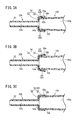
- FIG. 7A is an explanatory diagram schematically showing an engagement state between the opening member and the connector according to the second configuration example of the third embodiment.
- FIG. 7B is an explanatory diagram schematically showing an engagement state between the opening member and the connector according to the third configuration example of the third embodiment.
- FIG. 7C is an explanatory diagram schematically showing an engagement state between the opening member and the connector according to the fourth configuration example of the third embodiment.
- the catheter assembly 10A As shown in FIG. 1, the catheter assembly 10A according to the first embodiment of the present invention has a catheter 12 that is inserted and placed in the body of a patient (living body), and is liquid (medicine solution or blood) in infusion or blood transfusion. ) Is used to construct the entrance / exit part.
- the catheter 12 is configured as a peripheral venous catheter.
- the catheter 12 may be a catheter longer than a peripheral venous catheter (for example, a central venous catheter, a PICC, a midline catheter, etc.). Further, the catheter 12 is not limited to the intravenous catheter, and may be an arterial catheter such as a peripheral arterial catheter.
- the catheter assembly 10A has an operating body 18 composed of an inner needle 14 and a needle hub 16 fixed to the base end of the inner needle 14. Further, the catheter assembly 10A has a catheter indwelling body 22 composed of the above-mentioned catheter 12 and a catheter hub 20 fixed to the proximal end of the catheter 12.
- the operating body 18 is assembled to the base end of the catheter indwelling body 22 to form a multilayer structure needle 11 in which the internal needle 14 is inserted into the catheter 12. are doing.
- the multilayer structure needle 11 projects the needle tip 14a of the inner needle 14 from the tip of the catheter 12, and the inner needle 14 and the catheter 12 can be integrally punctured into the patient.
- a user such as a doctor or a nurse grips and operates the needle hub 16 when using the catheter assembly 10A to puncture the multi-structured needle 11 into the patient's body so that the needle tip 14a reaches the blood vessel. .. Further, the user inserts the catheter 12 into the blood vessel by advancing relative to the internal needle 14 while maintaining the punctured state. After that, the catheter indwelling body 22 is placed in the patient by retracting the inner needle 14 relative to the catheter 12 and further removing the inner needle 14 from the catheter hub 20. Then, in the catheter indwelling body 22, by connecting the connector 100 of the medical device (see FIG. 4) to the catheter hub 20, it becomes possible to perform treatments such as administration of a drug solution or blood to a patient and blood collection from the patient. ..
- each configuration of the catheter assembly 10A will be described in detail.
- the inner needle 14 of the catheter assembly 10A (operation body 18) is formed of a hollow tube (or a solid rod shape) having rigidity capable of puncturing the skin of a living body, and has a sharp needle tip 14a at its tip.
- the outer peripheral surface of the inner needle 14 is provided with a groove 24 for flashback that guides blood toward the proximal end side when a blood vessel is punctured.
- the structure for performing flashback is not particularly limited, and for example, a configuration having a hole (not shown) communicating with the inner space of the inner needle 14 on the proximal end side of the distal end of the catheter 12 may be provided.
- the catheter assembly 10A has a needle puncture prevention structure (a cover covering the needle tip 14a after puncture, a blunt needle protruding from the needle tip 14a, etc.) to prevent erroneous puncture of the needle tip 14a after the puncture of the inner needle 14. Good.
- a needle puncture prevention structure a cover covering the needle tip 14a after puncture, a blunt needle protruding from the needle tip 14a, etc.
- Examples of the constituent material of the inner needle 14 include metal materials such as stainless steel, aluminum or aluminum alloy, titanium or titanium alloy, hard resin, ceramics and the like.
- the inner needle 14 is firmly fixed to the needle hub 16 by an appropriate fixing means such as fusion, adhesion, and insert molding.
- the needle hub 16 constitutes a grip portion to be gripped by the user in the initial state in which the catheter indwelling body 22 and the operating body 18 are assembled.
- the needle hub 16 includes a hub body 26 that the user grips, and an inner needle support portion 28 that is integrally molded at the tip of the hub body 26.
- the hub body 26 is formed in a cylindrical shape on the base end side, while is gradually deformed into a square cylinder shape toward the tip end side.
- the inner needle support portion 28 is formed in a columnar shape protruding from the hub main body 26 toward the tip end, and holds the base end portion of the inner needle 14 at the central portion thereof.
- the constituent material of the needle hub 16 is not particularly limited, but for example, a thermoplastic resin such as polypropylene, polycarbonate, polyamide, polysulfone, polyarylate, and methacrylate-butylene-styrene copolymer can be applied.
- a thermoplastic resin such as polypropylene, polycarbonate, polyamide, polysulfone, polyarylate, and methacrylate-butylene-styrene copolymer can be applied.
- the catheter 12 of the catheter assembly 10A is formed of a flexible hollow tube having a lumen 12a formed inside.
- the outer shape and the lumen 12a of the catheter 12 are formed in a perfect circular shape in a cross-sectional view orthogonal to the axial direction, and extend along the axial direction of the catheter 12.
- the lumen 12a communicates with the tip opening 12a1 formed at the tip of the catheter 12 and the proximal opening 12a2 (see FIG. 2) formed at the proximal end of the catheter 12.
- the material constituting the catheter 12 is not particularly limited, but it is preferable to apply a transparent soft resin material.
- a fluororesin such as polytetrafluoroethylene (PTFE), an ethylene / tetrafluoroethylene copolymer (ETFE), a perfluoroalkoxy alkane resin (PFA), and an olefin resin such as polyethylene and polypropylene are used.
- PTFE polytetrafluoroethylene
- ETFE ethylene / tetrafluoroethylene copolymer
- PFA perfluoroalkoxy alkane resin
- an olefin resin such as polyethylene and polypropylene
- examples thereof include resins or mixtures thereof, polyurethanes, polyesters, polyamides, polyether nylon resins, olefin resins and ethylene / vinyl acetate copolymers.
- the length of the catheter 12 is not particularly limited and can be appropriately designed according to the application, various conditions, etc., and is set to, for example, about 14 to 500 mm.
- the proximal end of the catheter 12 is inserted and secured inside the catheter hub 20.
- the catheter hub 20 is exposed on the patient's skin with the catheter 12 inserted into the patient's blood vessel, attached with tape or the like, and placed together with the catheter 12.
- the material constituting the catheter hub 20 is not particularly limited, and for example, the material mentioned in the needle hub 16 may be appropriately adopted.
- the catheter hub 20 is formed in a cylindrical shape that tapers toward the tip end.
- a hollow portion 30 is provided inside the catheter hub 20.
- the hollow portion 30 holds the catheter 12 on the distal end side and communicates with the lumen 12a (base end opening 12a2). Further, the hollow portion 30 communicates with the proximal end opening portion 30a of the catheter hub 20 on the proximal end side.
- a flange 32 that projects outward in the radial direction and extends along the circumferential direction is provided on the outer peripheral surface of the catheter hub 20 on the proximal end side.
- the catheter 12 and the catheter hub 20 are fixed by appropriate fixing means such as caulking, fusion, and adhesion.
- the catheter pin 34 is inserted into the hollow portion 30 of the catheter hub 20, the catheter 12 is sandwiched between the inner wall 20a of the catheter hub 20 and the catheter pin 34, and the catheter pin 34 is crimped. The catheter 12 is fixed.
- the valve body 40, the opening member 50A, and the fixing member 70 are housed in the catheter hub 20.
- the valve body 40 divides the hollow portion 30 into a distal end side space 36 and a proximal end side space 38, and blood flowing into the hollow portion 30 from the lumen 12a of the catheter 12 leaks from the proximal end opening portion 30a. It is configured as a hemostatic valve to block the blood.
- An example of the valve body 40 is the application of a duck bill valve.
- valve body 40 has an annular portion 42 fixed to the inner wall 20a of the catheter hub 20, and a valve body 44 protruding from the annular portion 42 toward the tip end.
- the annulus 42 projects radially outward with respect to the valve body 44, and is configured as a block having a sufficient thickness in the axial direction of the catheter hub 20.
- the inner wall 20a of the catheter hub 20 is provided with a fixing structure 39 that prevents the annular portion 42 from moving in the axial direction when the valve body 40 is arranged.
- the fixed structure 39 is composed of a stepped portion 39a in which the diameter of the hollow portion 30 is slightly reduced, and a locking convex portion 39b protruding inward at a position away from the stepped portion 39a toward the proximal end side.
- valve body 44 is formed in a cylindrical shape with a base end side connected to the annular portion 42 having a cylindrical shape and a pair of inclined portions 46 approaching each other toward the tip end direction.
- Cylindrical side portions 49 are formed in adjacent portions of the pair of inclined portions 46 in the circumferential direction.
- a valve space 40a that narrows toward the tip is formed inside the valve body 40.
- the tips of the pair of inclined portions 46 form an extending end 47 extending in the width direction.
- the slit 48 of the valve body 40 is a cylinder formed between a front slit 48a formed along the longitudinal direction of the extending end 47 and a pair of inclined portions 46 from both ends of the extending end 47 when viewed from the front. It is composed of a side slit 48b formed on the side portion 49 of the shape.
- the front slit 48a and the side slit 48b are continuous.
- the side slit 48b extends parallel to the proximal end direction from the extending end 47 and extends to the tip of the annular portion 42.
- the ring portion 42, the pair of inclined portions 46, and the side portions 49 are inserted with the inner needle 14 through the slit 48 in the initial state of the catheter assembly 10A, and the slit 48 is removed as the inner needle 14 is removed from the valve body 40. Is shaped to self-occlude. Further, the pair of inclined portions 46 open (open) the slits 48 at a large distance from each other by inserting the opening member 50A arranged on the base end side of the valve body 40 (see also FIG. 4).
- the configuration of the valve body 40 is not limited to the duck bill valve, and various configurations may be adopted. For example, as the valve body 40, a disc valve having a flat membrane may be applied.
- the opening member 50A is arranged on the proximal end side of the hollow portion 30 with respect to the valve body 44. Specifically, the opening member 50A is arranged at an initial position on the distal end side of the fixing member 70 in the proximal end side space 38 in the catheter hub 20.
- the opening member 50A has a cylindrical nozzle portion 52 and a base end tubular portion 54 which is connected to the base end of the nozzle portion 52 and is formed to have a diameter larger than that of the nozzle portion 52.
- a flow passage 52a capable of flowing a liquid is formed inside the nozzle portion 52.
- a space portion 54a is formed which communicates with the flow passage 52a and into which the connector 100 of the medical device (see FIG. 3A) is inserted.
- the nozzle portion 52 When the opening member 50A moves in the tip direction relative to the valve body 40, the nozzle portion 52 penetrates the slit 48 of the valve body 40 and pushes out the valve body 44 (a pair of inclined portions 46).
- the nozzle portion 52 is formed in a cylindrical shape having a diameter sufficiently smaller than the diameter of the hollow portion 30 of the catheter hub 20.
- the outer diameter and inner diameter of the nozzle portion 52 extend constantly along the axial direction of the nozzle portion 52.
- the nozzle portion 52 may be formed in a tapered shape or the like that gradually tapers toward the tip end.
- the flow passage 52a of the nozzle portion 52 extends along the axial direction of the nozzle portion 52, and its tip communicates with the tip opening 52a1 formed at the tip of the nozzle portion 52.
- the tip end side of the nozzle portion 52 is arranged inside the annular portion 42 of the valve body 40 (valve space 40a) in the initial state. Further, a tapered surface having a smaller diameter toward the tip is formed on the outer peripheral surface of the nozzle portion 52 on the tip end side.
- the base end cylinder portion 54 provided at the base end of the nozzle portion 52 has a cylindrical shape that extends shortly in the axial direction of the opening member 50A.
- the axial length of the base end tubular portion 54 is sufficiently shorter than the axial length of the nozzle portion 52.
- the axial length of the base end cylinder portion 54 is preferably set to 1/2 or less of the axial length of the nozzle portion 52.
- the base end cylinder portion 54 extends radially outward from the base end of the nozzle portion 52 to a disk-shaped end wall portion 56 and extends from the outer edge of the end wall portion 56 in the proximal end direction. It is composed of a side wall portion 58.
- the end wall portion 56 constitutes a bottom portion that closes the tip portion of the proximal end cylinder portion 54, and the distal end surface and the proximal end surface thereof are formed flat.
- the side wall portion 58 is formed in a tapered shape in which the diameter gradually increases from the outer edge of the end wall portion 56 toward the base end.
- the diameter of the outer peripheral surface 58a of the side wall portion 58 is slightly smaller than the diameter of the inner wall 20a constituting the base end side space 38, and substantially coincides with the diameter of the outer peripheral surface on the tip end side of the fixing member 70.
- the side wall portion 58 moves to a position close to the inner wall 20a when the opening member 50A is displaced.
- the proximal end cylinder portion 54 interferes with the fixing member 70 in the housed state of the catheter hub 20, so that the opening member 50A is prevented from being detached from the proximal end direction.
- the diameter of the inner peripheral surface 58b (space portion 54a) of the side wall portion 58 is larger than the diameter of the inner peripheral surface on the tip end side of the fixing member 70 (or substantially matches the diameter of the inner peripheral surface). Further, the diameter of the inner peripheral surface 58b is set to be slightly larger than the diameter (outer diameter) of the distal end side outer peripheral surface 102 (see FIG. 3A) of the connector 100.
- the opening member 50A includes an engaging portion 60 that engages with the connector 100 on the base end tubular portion 54 (side wall portion 58).
- the engaging portion 60 applies a plurality of protruding portions 62 protruding inward in the radial direction from the inner peripheral surface 58b.
- the plurality of protrusions 62 are provided at equal intervals on the proximal end side of the side wall portion 58 along the circumferential direction.
- Each protrusion 62 is formed in a triangular shape having a top 62a in a side sectional view along the axial direction of the opening member 50A, and the top 62a bites into the outer peripheral surface 102 on the tip end side of the connector 100 as the connector 100 is inserted. It is configured to form an anchor).
- the amount of protrusion of each protrusion 62 (top 62a) from the inner peripheral surface 58b is small with respect to the diameter of the inner peripheral surface 58b.
- each top portion 62a is formed on the side wall portion 58 so as to be located inside within a range of about 0.01 mm to 1 mm with respect to the diameter of the outer peripheral surface 102 on the tip end side of the connector 100.
- the protrusion 62 may be provided at one or more on the side wall portion 58, or may be formed in a ring shape which is continuous in a series along the circumferential direction of the side wall portion 58.
- the cross-sectional shape of the protrusion 62 is not particularly limited, and may be formed into a right triangle whose base end side is inclined and whose tip end side is perpendicular to the inner peripheral surface 58b, and is formed in a quadrangular shape or a semicircular shape. You may.
- the configuration of the engaging portion 60 that engages with the connector 100 is not limited to the protrusion 62, and various configurations may be adopted.
- the engaging portion 60 may be configured by applying one or more elastic pieces 64 that elastically project inward in the radial direction of the side wall portion 58.
- the elastic piece 64 is formed in an arc shape that curves inward in the radial direction from the connecting portion at the tip toward the proximal end and extends radially outward from the valley portion in the middle.
- the elastic piece 64 engages with the connector 100 by generating an appropriate frictional force between the inner surface of the valley portion and the outer peripheral surface 102 on the tip end side of the connector 100.
- the engaging portion 60 appropriately adjusts the shape (diameter) of the inner peripheral surface 58b of the side wall portion 58 according to the diameter of the distal end side outer peripheral surface 102 of the connector 100.
- it may be configured to fit with the outer peripheral surface 102 on the tip side.
- the base end of the inner peripheral surface 58b is preferably formed on a tapered surface so that the connector 100 can be easily inserted.
- the side wall portion 58 may be provided with various configurations (coating, roughening of the inner peripheral surface 58b, etc.) for improving the frictional resistance with the outer peripheral surface 102 on the tip end side.
- the engaging portion 60 is provided with a structure of adsorbing to the outer peripheral surface 102 on the tip side (sucker or the like) and a structure of detachably adhering to the outer peripheral surface 102 of the tip side (adhesive or the like). obtain.
- the configuration in which the connector 100 is engaged by biting, frictional force, suction, adhesion, etc. does not change the configuration of the conventional connector 100, and is therefore easy to use as the engaging portion 60. There are merits.
- the material constituting the opening member 50A is not particularly limited, but an appropriate material may be applied according to the type of the engaging portion 60 described above.
- the material mentioned in the needle hub 16 or the like may be applied.
- a material harder than the connector 100 may be applied in the case of a configuration that bites into the connector 100 (protrusion portion 62) or a configuration that fits by frictional force.
- a material more flexible than the connector 100 may be applied.
- the fixing member 70 is provided on the proximal end side of the catheter hub 20 and functions as a regulating portion for restricting the opening member 50A from falling off.
- the fixing member 70 is formed in a cylindrical shape, and is fixed to the catheter hub 20 by fitting the opening member 50A into the inner wall 20a of the catheter hub 20 in a state of being housed in the hollow portion 30.
- the fixing means of the catheter hub 20 and the fixing member 70 is not particularly limited, and may be adhesion, fusion, or the like.
- the fixing member 70 includes a fixed tubular body 72 having a through hole 72a and an annular convex portion 74 provided at the base end of the fixed tubular body 72.
- the proximal end of the fixed cylinder 72 constitutes the proximal end opening portion 30a of the catheter hub 20.
- the annular convex portion 74 is arranged in the annular groove portion 32a inside the flange 32 formed at the base end of the catheter hub 20 to regulate the displacement of the fixing member 70 toward the tip end.
- the opening member 50A and the fixing member 70 have a structure that regulates the rotation of the opening member 50A with respect to the catheter hub 20 in the circumferential direction (for example, a projecting piece portion (not shown) is provided on one side, and a recess (not shown) capable of accommodating the projecting piece portion is provided on the other side.
- the structure provided in 1) may be applied.
- the catheter assembly 10A according to the present embodiment is basically configured as described above, and its operation will be described below.
- the catheter assembly 10A is used when constructing an inlet / outlet part for infusion, blood transfusion, blood collection, etc. to a patient.
- the user grips the needle hub 16 of the catheter assembly 10A in the initial state shown in FIG. 1 to puncture the patient with the multi-structured needle 11.
- the user advances the catheter 12 relative to the inner needle 14 to insert the catheter 12 into the blood vessel, and when the catheter 12 is inserted into the blood vessel to some extent, the user retracts the inner needle 14 with respect to the catheter 12. ..
- the inner needle 14 is separated from the base end opening portion 30a of the catheter hub 20, the operating body 18 is separated from the catheter indwelling body 22, and the catheter indwelling body 22 is indwelled in the patient.
- the slit 48 is closed.
- the state of the catheter indwelling body 22 at this time is shown in FIG. 2, and the position of the opening member 50A is set as the first position.
- the user attaches the connector 100 of the medical device (infusion line, blood transfusion line tube, syringe, etc.) from the base end opening portion 30a of the catheter hub 20. It is inserted into the hollow portion 30.
- the connector 100 moves in the base end side space 38 in the distal end direction, its distal end surface reaches the proximal end tubular portion 54 of the opening member 50A.
- the opening member 50A at the first position is pushed out toward the tip end.
- the opening member 50A receives some resistance from the inner wall 20a of the catheter hub 20 and the valve body 40 when displaced in the distal direction.
- the outer peripheral surface 102 on the tip end side of the connector 100 gets over the protrusion 62 and advances in the space portion 54a of the base end cylinder portion 54 toward the tip end.
- the protrusion 62 strongly bites into the tapered outer peripheral surface 102 on the tip end side at an appropriate position to form an anchor.
- the opening member 50A and the connector 100 are in an engaged state.
- the opening member 50A moves inside the valve body 40 as the connector 100 is pushed in, and the nozzle portions 52 separate the pair of inclined portions 46 from each other to open the slit 48.
- the nozzle portion 52 greatly separates the pair of inclined portions 46.
- the state of the catheter indwelling body 22 at this time is shown in FIG. 4A, and the position of the opening member 50A is set as the second position.
- the connector 100 allows liquid (infusion, blood, etc.) to flow into the catheter indwelling body 22 from the flow path 100a in a state where the connector 100 is tapered and fitted with the fixing member 70.
- This chemical solution flows in the flow passage 52a of the opening member 50A toward the tip end, flows out from the tip opening 52a1 of the nozzle portion 52 to the tip end side of the valve body 40, and further flows from the tip end side space 36 to the lumen 12a of the catheter 12. Inflow to.
- the drug solution that has flowed into the lumen 12a is administered through the tip opening 12a1 of the catheter 12 inserted into the blood vessel of the patient.
- the connector 100 when the connector 100 is removed after administration, the connector 100 is displaced in the proximal direction relative to the catheter hub 20. At this time, since the protrusion 62 (engagement portion 60) of the opening member 50A is engaged with the outer peripheral surface 102 on the tip end side, the connector 100 is displaced following the retreat. That is, in the valve body 40, when the opening member 50A is pulled out, the valve body 44 is elastically restored and the slit 48 is closed. Therefore, the valve body 40 prevents the liquid in the front end side space 36 from leaking to the base end side.
- the opening member 50A can open the valve body 40 by the same operation as described above. That is, the catheter assembly 10A can suppress the leakage of liquid while performing a plurality of infusions and blood transfusions by the operation of the valve body 40 and the opening member 50A.
- the engaging portion 60 is not limited to being provided on the side wall portion 58 of the opening member 50A.
- the engaging portion 60 may be provided on the end wall portion 56 with which the tip surface of the connector 100 comes into contact.
- FIGS. 5A to 7C elements having the same configuration or the same function as those in the above embodiment are designated by the same reference numerals, and detailed description thereof will be omitted.
- the catheter assembly 10B according to the second embodiment includes an opening member 50B having an engaging portion 80 capable of engaging with the distal inner peripheral surface 104 of the connector 100. Therefore, it is different from the above-mentioned catheter assembly 10A.
- the base end cylinder portion 82 connected to the base end of the nozzle portion 52 is configured to be insertable into the flow path 100a of the connector 100 and elastically deformable, so that the entire base end cylinder portion 82 is engaged. Functions as a joint 80.
- the diameter of the proximal cylinder portion 82 is once increased radially outward from the tip toward the proximal end, and is decreased radially inward from a substantially intermediate position in the axial direction toward the proximal end.
- the portion of the base end cylinder portion 82 that protrudes most radially outward is located radially outside the diameter of the flow path 100a of the connector 100 in the initial state in which the connector 100 is not inserted, and is inside the tip end side of the connector 100.
- a side wall portion 84 that can come into contact with the peripheral surface 104 is formed.
- the side wall portion 84 can be elastically displaced inward in the radial direction due to elastic deformation of the base end cylinder portion 82, and when the base end cylinder portion 82 enters the flow path 100a of the connector 100, the distal end side inner peripheral surface. Engage with 104 with an appropriate frictional force.
- the most projecting base end 82a in the base end cylinder portion 82 in the base end direction is located radially inside the diameter of the flow path 100a of the connector 100. Therefore, when the connector 100 advances, the connector 100 can guide the most basic end 82a to the flow path 100a.
- a protrusion 86 protruding outward in the radial direction is provided on the distal end side of the side wall portion 84.
- the protrusion 86 restricts the movement of the connector 100 with respect to the opening member 50B in the direction of the tip when the tip of the connector 100 comes into contact with the protrusion 86.
- the protrusion 86 is hooked on the fixing member 70 when the connector 100 is retracted to disengage the base end cylinder portion 82 from the connector 100.
- the opening member 50B of the catheter assembly 10B according to the second embodiment is basically configured as described above.
- the catheter assembly 10B engages the side wall portion 84 with the connector 100 as the connector 100 is inserted into the catheter hub 20 (see FIG. 4A).
- the connector 100 advances in the tip direction, the most basic end 82a enters the flow path 100a.
- the base end tubular portion 82 is elastically deformed and relatively moved toward the tip end with respect to the opening member 50B that receives resistance from the inner wall 20a of the catheter hub 20 and the valve body 40, and the connector 100 is at the maximum.
- the tip gets over the side wall portion 84.
- the base end tubular portion 82 is slightly elastically restored so as to expand outward in the radial direction, and the side wall portion 84 and the tip side inner peripheral surface 104 have an appropriate engaging force (friction force). ) To engage with each other.
- the connector 100 further advances, it comes into contact with the protrusion 86 and the opening member 50B can be reliably pushed out.
- the engaging portion 80 is not limited to the configuration in which it engages with the inner peripheral surface 104 on the tip end side of the connector 100 by frictional force (elastic force), and has a configuration in which it engages by biting, suction, adhesion, or the like described above. Of course you can get it.
- the catheter assembly 10C according to the third embodiment includes the engaging portion 90 in the opening member 50C, while the engaged portion 110 that can be engaged with the engaging portion 90 is provided. It differs from the above catheter assemblies 10A and 10B in that the connector 100 is provided.
- the opening member 50C is provided with a fastener portion 92 formed in a planar shape as an engaging portion 90 in the base end cylinder portion 54.
- the fastener portion 92 is provided, for example, over the entire circumference of the inner peripheral surface 58b of the base end tubular portion 54 (side wall portion 58) in the circumferential direction, and a large number of minute hooks are raised on the inner surface thereof.
- the connector 100 includes a joint portion 112 formed in a planar shape as an engaged portion 110 on the outer peripheral surface 102 on the tip end side.
- the joint portion 112 is also provided, for example, over the entire circumference of the distal end side outer peripheral surface 102 in the circumferential direction, and a large number of minute loops are raised on the outer surface thereof.
- the fastener portion 92 and the joint portion 112 may not be provided on the entire circumference in the circumferential direction, but may be provided on a part in the circumferential direction.
- the engaging portion 90 (fastener portion 92) and the engaged portion 110 (joining portion 112) engage the opening member 50C and the connector 100 more smoothly with an appropriate engaging force. be able to. Therefore, when the connector 100 is retracted, the opening member 50C can be made to follow well and the valve body 40 can be closed.
- the engaging portion 90 and the engaged portion 110 are not limited to the above structures and may have various structures.
- the first magnetic body 94 is applied as the engaging portion 90, while being adsorbed by the first magnetic body 94 as the engaged portion 110.
- the second magnetic material 114 can be applied.
- the protrusion 96 is applied as the engaging portion 90, while the protrusion 96 is inserted (fitted) as the engaged portion 110.
- the recessed portion 116 can be applied.
- the recessed portion 116 may be applied to the engaging portion 90, while the protruding portion 96 may be applied to the engaged portion 110.
- the female screw portion 98 is applied as the engaging portion 90, while the female screw portion 98 is screwed as the engaged portion 110.
- Threaded portion 118 can be applied.
- the male screw portion 118 is applied to the engaging portion 90, while the female screw portion 98 is applied to the engaged portion 110. Just do it.
- the catheter assemblies 10A to 10C may be configured by applying a plurality of types of the configurations of the engaging portions 60, 80, 90 and the engaged portions 110 described above.
- the catheter assemblies 10A to 10C are provided with engaging portions 60, 80, 90 on the opening members 50A to 50C, so that the opening members 50A to 50C and the connector 100 can be easily engaged with each other as the connector 100 advances. That is, the engaging portions 60, 80, 90 can open the valve body 40 by integrating the opening members 50A to 50C and the connector 100 without requiring a large operating force. Further, the catheter assemblies 10A to 10C can retract the opening members 50A to 50C following the connector 100 by engaging the engaging portions 60, 80, 90 when the connector 100 is disengaged. As a result, the valve body 40 can be smoothly closed from the opened state and the leakage of the liquid can be suppressed.
- the engaging portions 60, 80, 90 are provided on the tubular side wall portions 58, 84 formed at the base ends of the opening members 50A to 50C.
- the catheter assemblies 10A to 10C can satisfactorily engage the connector 100 with the side wall portions 58, 84 having the engaging portions 60, 80, 90.
- the side wall portion 58 has a configuration in which the connector 100 is inserted inside, and the engaging portions 60 and 90 can be engaged with the outer peripheral surface 102 on the tip end side of the connector 100. As a result, the engaging portions 60 and 90 can be smoothly engaged with the distal end side outer peripheral surface 102 when the connector 100 is inserted.
- the side wall portion 84 is configured to be inserted into the flow path 100a of the connector 100, and the engaging portion 80 can be engaged with the inner peripheral surface 104 on the tip end side of the connector 100. As a result, the engaging portion 80 can be smoothly engaged with the tip side inner peripheral surface 104 when the connector 100 is inserted.
- the opening member 50A is formed harder than the connector 100, and the engaging portion 60 is a protrusion 62 capable of forming an anchor with respect to the connector 100.
- the protruding portion 62 of the engaging portion 60 is firmly hooked on the connector 100, and the engaged portion 60 can maintain a good engaged state when the opening member 50A is retracted from the valve body 40.
- the opening member 50A is configured to be softer than the connector 100, and the engaging portion 60 engages with the connector 100 by any one of frictional force, suction and adhesion. As a result, the engaging portion 60 can be engaged with the connector 100 with a sufficient engaging force.
- the engaging portion 90 engages with the engaged portion 110 provided on the connector 100. As a result, the engaging portion 90 and the engaged portion 110 can be more easily engaged when the connector 100 is inserted.
- the engaging portion 90 and the engaged portion 110 are engaged with each other by any one of frictional force, magnetic coupling force, fitting, and screwing. As a result, the engaging portion 90 and the engaged portion 110 can be engaged with each other with a strong engaging force, and the opening member 50C and the connector 100 can be integrated.
- the engaging portions 60, 80, 90 separate the connector 100 and the opening members 50A to 50C when the opening members 50A to 50C move to the first position as the connector 100 retracts in the proximal direction. ..
- the catheter assemblies 10A to 10C can leave the opening members 50A to 50C in the catheter hub 20 when the connector 100 is detached, and can be used a plurality of times satisfactorily.
- the catheter hub 20 has a regulating portion (fixing member 70) that regulates the movement of the opening members 50A to 50C in the proximal end direction in a state where the opening members 50A to 50C are located at the first position.
- the catheter assemblies 10A to 10C can smoothly separate the connector 100 from the opening members 50A to 50C.
Landscapes
- Health & Medical Sciences (AREA)
- Life Sciences & Earth Sciences (AREA)
- Heart & Thoracic Surgery (AREA)
- Biomedical Technology (AREA)
- Engineering & Computer Science (AREA)
- Anesthesiology (AREA)
- Pulmonology (AREA)
- Hematology (AREA)
- Animal Behavior & Ethology (AREA)
- General Health & Medical Sciences (AREA)
- Public Health (AREA)
- Veterinary Medicine (AREA)
- Biophysics (AREA)
- Infusion, Injection, And Reservoir Apparatuses (AREA)
Abstract
L'invention concerne un ensemble cathéter (10A) comprenant un cathéter (12), un raccord de cathéter (20), un corps de valve (40), et un élément d'ouverture (50A) pour ouvrir le corps de valve (40) par avancement d'un élément de liaison (100) introduit dans le raccord de cathéter (20). L'élément d'ouverture (50A) comprend une partie de mise en prise (60) qui vient en prise avec l'élément de liaison (100) lorsque celui-ci avance dans la direction distale, et qui amène l'élément d'ouverture (50A) à se rétracter à partir du corps de valve (40) tout en demeurant en prise avec l'élément de liaison (100) lorsque celui-ci se rétracte dans la direction proximale.
Priority Applications (2)
| Application Number | Priority Date | Filing Date | Title |
|---|---|---|---|
| JP2021507259A JPWO2020189468A1 (fr) | 2019-03-18 | 2020-03-12 | |
| US17/465,467 US20210393920A1 (en) | 2019-03-18 | 2021-09-02 | Catheter assembly |
Applications Claiming Priority (2)
| Application Number | Priority Date | Filing Date | Title |
|---|---|---|---|
| JP2019049385 | 2019-03-18 | ||
| JP2019-049385 | 2019-03-18 |
Related Child Applications (1)
| Application Number | Title | Priority Date | Filing Date |
|---|---|---|---|
| US17/465,467 Continuation US20210393920A1 (en) | 2019-03-18 | 2021-09-02 | Catheter assembly |
Publications (1)
| Publication Number | Publication Date |
|---|---|
| WO2020189468A1 true WO2020189468A1 (fr) | 2020-09-24 |
Family
ID=72521012
Family Applications (1)
| Application Number | Title | Priority Date | Filing Date |
|---|---|---|---|
| PCT/JP2020/010685 WO2020189468A1 (fr) | 2019-03-18 | 2020-03-12 | Ensemble cathéter |
Country Status (3)
| Country | Link |
|---|---|
| US (1) | US20210393920A1 (fr) |
| JP (1) | JPWO2020189468A1 (fr) |
| WO (1) | WO2020189468A1 (fr) |
Cited By (1)
| Publication number | Priority date | Publication date | Assignee | Title |
|---|---|---|---|---|
| CN113616877A (zh) * | 2021-08-06 | 2021-11-09 | 首都医科大学宣武医院 | 一种带有阀的留置针组件 |
Families Citing this family (1)
| Publication number | Priority date | Publication date | Assignee | Title |
|---|---|---|---|---|
| US20230248956A1 (en) * | 2022-02-10 | 2023-08-10 | St. Jude Medical, Cardiology Division, Inc. | Integrated Hemostasis Bypass Valve |
Citations (1)
| Publication number | Priority date | Publication date | Assignee | Title |
|---|---|---|---|---|
| WO2013051242A1 (fr) * | 2011-10-05 | 2013-04-11 | 二プロ株式会社 | Cathéter à demeure |
Family Cites Families (1)
| Publication number | Priority date | Publication date | Assignee | Title |
|---|---|---|---|---|
| US9358364B2 (en) * | 2011-10-06 | 2016-06-07 | Becton, Dickinson And Company | Activator attachment for blood control catheters |
-
2020
- 2020-03-12 WO PCT/JP2020/010685 patent/WO2020189468A1/fr active Application Filing
- 2020-03-12 JP JP2021507259A patent/JPWO2020189468A1/ja active Pending
-
2021
- 2021-09-02 US US17/465,467 patent/US20210393920A1/en active Pending
Patent Citations (1)
| Publication number | Priority date | Publication date | Assignee | Title |
|---|---|---|---|---|
| WO2013051242A1 (fr) * | 2011-10-05 | 2013-04-11 | 二プロ株式会社 | Cathéter à demeure |
Cited By (1)
| Publication number | Priority date | Publication date | Assignee | Title |
|---|---|---|---|---|
| CN113616877A (zh) * | 2021-08-06 | 2021-11-09 | 首都医科大学宣武医院 | 一种带有阀的留置针组件 |
Also Published As
| Publication number | Publication date |
|---|---|
| JPWO2020189468A1 (fr) | 2020-09-24 |
| US20210393920A1 (en) | 2021-12-23 |
Similar Documents
| Publication | Publication Date | Title |
|---|---|---|
| JP7179042B2 (ja) | 摩擦に基づく保持力および使用不可機能を持つ安全な静脈カテーテル | |
| US11452858B2 (en) | Intravenous catheter with pressure activated valve | |
| US7985232B2 (en) | Detachable hemostasis valve and splittable sheath assembly | |
| US7247148B2 (en) | Protector and storage needle assembly | |
| US7040598B2 (en) | Self-sealing male connector | |
| RU2742869C2 (ru) | Внутривенный катетер с функцией безопасности и клапанным элементом, управляемым давлением | |
| JP6872488B2 (ja) | カテーテル組立体 | |
| US8192404B2 (en) | Indwelling needle assembly | |
| WO2014140265A9 (fr) | Ensembles cathéters à valve | |
| JP2010524586A (ja) | 進入装置 | |
| US11850377B2 (en) | Catheter assemblies and related methods | |
| US20210393920A1 (en) | Catheter assembly | |
| JP2024020412A (ja) | カテーテル組立体 | |
| JP7424680B2 (ja) | 静脈内カテーテルデバイス | |
| AU2019409703A1 (en) | Over-the-needle catheter assemblies and related manufacturing method | |
| WO2020189466A1 (fr) | Ensemble cathéter | |
| US20220203073A1 (en) | Catheter assembly | |
| JP6678379B2 (ja) | 隔壁付きハブ組立体 | |
| WO2020189467A1 (fr) | Ensemble cathéter | |
| JP7391040B2 (ja) | カテーテル組立体及びカテーテル留置体 | |
| WO2019188741A1 (fr) | Ensemble cathéter | |
| WO2022214490A1 (fr) | Dispositif d'évent, ensemble orifice et ensemble d'accès vasculaire | |
| JP2019195721A (ja) | 隔壁部材付きハブ組立体 |
Legal Events
| Date | Code | Title | Description |
|---|---|---|---|
| 121 | Ep: the epo has been informed by wipo that ep was designated in this application |
Ref document number: 20774300 Country of ref document: EP Kind code of ref document: A1 |
|
| ENP | Entry into the national phase |
Ref document number: 2021507259 Country of ref document: JP Kind code of ref document: A |
|
| NENP | Non-entry into the national phase |
Ref country code: DE |
|
| 122 | Ep: pct application non-entry in european phase |
Ref document number: 20774300 Country of ref document: EP Kind code of ref document: A1 |