WO2020189468A1 - Catheter assembly - Google Patents
Catheter assembly Download PDFInfo
- Publication number
- WO2020189468A1 WO2020189468A1 PCT/JP2020/010685 JP2020010685W WO2020189468A1 WO 2020189468 A1 WO2020189468 A1 WO 2020189468A1 JP 2020010685 W JP2020010685 W JP 2020010685W WO 2020189468 A1 WO2020189468 A1 WO 2020189468A1
- Authority
- WO
- WIPO (PCT)
- Prior art keywords
- connector
- catheter
- catheter assembly
- opening member
- valve body
- Prior art date
Links
Images


Classifications
-
- A—HUMAN NECESSITIES
- A61—MEDICAL OR VETERINARY SCIENCE; HYGIENE
- A61M—DEVICES FOR INTRODUCING MEDIA INTO, OR ONTO, THE BODY; DEVICES FOR TRANSDUCING BODY MEDIA OR FOR TAKING MEDIA FROM THE BODY; DEVICES FOR PRODUCING OR ENDING SLEEP OR STUPOR
- A61M25/00—Catheters; Hollow probes
- A61M25/0097—Catheters; Hollow probes characterised by the hub
-
- A—HUMAN NECESSITIES
- A61—MEDICAL OR VETERINARY SCIENCE; HYGIENE
- A61M—DEVICES FOR INTRODUCING MEDIA INTO, OR ONTO, THE BODY; DEVICES FOR TRANSDUCING BODY MEDIA OR FOR TAKING MEDIA FROM THE BODY; DEVICES FOR PRODUCING OR ENDING SLEEP OR STUPOR
- A61M25/00—Catheters; Hollow probes
- A61M25/01—Introducing, guiding, advancing, emplacing or holding catheters
- A61M25/06—Body-piercing guide needles or the like
-
- A—HUMAN NECESSITIES
- A61—MEDICAL OR VETERINARY SCIENCE; HYGIENE
- A61M—DEVICES FOR INTRODUCING MEDIA INTO, OR ONTO, THE BODY; DEVICES FOR TRANSDUCING BODY MEDIA OR FOR TAKING MEDIA FROM THE BODY; DEVICES FOR PRODUCING OR ENDING SLEEP OR STUPOR
- A61M39/00—Tubes, tube connectors, tube couplings, valves, access sites or the like, specially adapted for medical use
- A61M39/02—Access sites
- A61M39/06—Haemostasis valves, i.e. gaskets sealing around a needle, catheter or the like, closing on removal thereof
- A61M2039/062—Haemostasis valves, i.e. gaskets sealing around a needle, catheter or the like, closing on removal thereof used with a catheter
-
- A—HUMAN NECESSITIES
- A61—MEDICAL OR VETERINARY SCIENCE; HYGIENE
- A61M—DEVICES FOR INTRODUCING MEDIA INTO, OR ONTO, THE BODY; DEVICES FOR TRANSDUCING BODY MEDIA OR FOR TAKING MEDIA FROM THE BODY; DEVICES FOR PRODUCING OR ENDING SLEEP OR STUPOR
- A61M25/00—Catheters; Hollow probes
- A61M25/01—Introducing, guiding, advancing, emplacing or holding catheters
- A61M25/06—Body-piercing guide needles or the like
- A61M25/0606—"Over-the-needle" catheter assemblies, e.g. I.V. catheters
-
- A—HUMAN NECESSITIES
- A61—MEDICAL OR VETERINARY SCIENCE; HYGIENE
- A61M—DEVICES FOR INTRODUCING MEDIA INTO, OR ONTO, THE BODY; DEVICES FOR TRANSDUCING BODY MEDIA OR FOR TAKING MEDIA FROM THE BODY; DEVICES FOR PRODUCING OR ENDING SLEEP OR STUPOR
- A61M39/00—Tubes, tube connectors, tube couplings, valves, access sites or the like, specially adapted for medical use
- A61M39/22—Valves or arrangement of valves
- A61M39/26—Valves closing automatically on disconnecting the line and opening on reconnection thereof
Definitions
- the present invention relates to a catheter assembly including a valve body that prevents blood from flowing out and an opening member that opens the valve body.
- the catheter assembly that functions as an indwelling needle.
- the catheter assembly (catheter assembly) disclosed in Japanese Patent Application Laid-Open No. 2014-528807 includes a catheter and a catheter hub (catheter adapter) fixed to the catheter.
- the catheter assembly is punctured by the patient with an introduction needle housed within the catheter, after which the introduction needle is detached from the catheter and catheter hub.
- the catheter assembly becomes an inlet / outlet portion for a drug solution or blood by inserting a connector of a medical device (infusion solution or blood transfusion tube) into the catheter hub after withdrawal.
- a valve body (septum) for preventing blood leakage during indwelling and an opening member (actuator) for opening the valve body are provided in the catheter hub. Be prepared. The opening member is pushed out by the connector inserted into the catheter hub to open the slit of the valve body so that the liquid can flow.
- the opening state of the valve body is continued after the opening member once opens the slit of the valve body. Therefore, after disconnecting the connector from the catheter hub, blood, infusion, or the like leaks from the base end of the catheter hub.
- a mechanism for pulling out the opening member from the valve body when the connector is disconnected is also conceivable.
- Examples of this type of mechanism include a valve body having a high repulsive force and a spring that urges an opening member in the proximal direction.
- this type of mechanism causes another inconvenience of making it difficult to push the opening member into the valve body when the connector is inserted.
- the present invention is for solving the above-mentioned problems, and while opening the valve body with the insertion of the connector without requiring a large operating force, the valve body is closed with the disconnection of the connector to form a liquid. It is an object of the present invention to provide a catheter assembly capable of preventing leakage of the catheter.
- one aspect of the present invention includes a catheter, a catheter hub provided at the proximal end of the catheter, a valve body fixed in the catheter hub, and housed in the catheter hub.
- a catheter assembly comprising an opening member for opening the valve body, the opening member being advanced by a first position on the proximal end side of the valve body and a connector inserted into the catheter hub.
- the opening member is provided with an engaging portion, so that the opening member and the connector can be easily engaged with each other as the connector advances. That is, the engaging portion can open the valve body by integrating the opening member and the connector without requiring a large operating force. Further, the catheter assembly can follow the connector and retract the opening member by engaging the engaging portion when the connector is disengaged. As a result, the valve body can be smoothly closed from the opened state and the leakage of liquid can be suppressed.
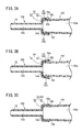
- FIG. 3A is an explanatory diagram schematically showing an engagement state between the opening member and the connector according to the first configuration example of the first embodiment.
- FIG. 3B is an explanatory diagram schematically showing an engagement state between the opening member and the connector according to the second configuration example of the first embodiment.
- FIG. 3C is an explanatory diagram schematically showing an engagement state between the opening member and the connector according to the third configuration example of the first embodiment.
- FIG. 4A is a first explanatory view showing the operation of the opening member when the connector is inserted.
- FIG. 4B is a second explanatory view showing the operation of the opening member when the connector is inserted.
- FIG. 5A is a first explanatory view schematically showing an engagement state between the opening member and the connector of the catheter assembly according to the second embodiment of the present invention.
- FIG. 5B is a second explanatory view schematically showing an engaged state of the opening member and the connector following FIG. 5A.
- FIG. 5C is a third explanatory view schematically showing an engagement state between the opening member and the connector following FIG. 5B.
- FIG. 6A is a first side sectional view showing an opening member and a connector of a first configuration example of the catheter assembly according to the third embodiment.
- FIG. 6B is a second side sectional view showing an engaged state of the opening member and the connector following FIG. 6A.
- FIG. 6A is a first side sectional view showing an opening member and a connector of a first configuration example of the catheter assembly according to the third embodiment.
- FIG. 6B is a second side sectional view
- FIG. 7A is an explanatory diagram schematically showing an engagement state between the opening member and the connector according to the second configuration example of the third embodiment.
- FIG. 7B is an explanatory diagram schematically showing an engagement state between the opening member and the connector according to the third configuration example of the third embodiment.
- FIG. 7C is an explanatory diagram schematically showing an engagement state between the opening member and the connector according to the fourth configuration example of the third embodiment.
- the catheter assembly 10A As shown in FIG. 1, the catheter assembly 10A according to the first embodiment of the present invention has a catheter 12 that is inserted and placed in the body of a patient (living body), and is liquid (medicine solution or blood) in infusion or blood transfusion. ) Is used to construct the entrance / exit part.
- the catheter 12 is configured as a peripheral venous catheter.
- the catheter 12 may be a catheter longer than a peripheral venous catheter (for example, a central venous catheter, a PICC, a midline catheter, etc.). Further, the catheter 12 is not limited to the intravenous catheter, and may be an arterial catheter such as a peripheral arterial catheter.
- the catheter assembly 10A has an operating body 18 composed of an inner needle 14 and a needle hub 16 fixed to the base end of the inner needle 14. Further, the catheter assembly 10A has a catheter indwelling body 22 composed of the above-mentioned catheter 12 and a catheter hub 20 fixed to the proximal end of the catheter 12.
- the operating body 18 is assembled to the base end of the catheter indwelling body 22 to form a multilayer structure needle 11 in which the internal needle 14 is inserted into the catheter 12. are doing.
- the multilayer structure needle 11 projects the needle tip 14a of the inner needle 14 from the tip of the catheter 12, and the inner needle 14 and the catheter 12 can be integrally punctured into the patient.
- a user such as a doctor or a nurse grips and operates the needle hub 16 when using the catheter assembly 10A to puncture the multi-structured needle 11 into the patient's body so that the needle tip 14a reaches the blood vessel. .. Further, the user inserts the catheter 12 into the blood vessel by advancing relative to the internal needle 14 while maintaining the punctured state. After that, the catheter indwelling body 22 is placed in the patient by retracting the inner needle 14 relative to the catheter 12 and further removing the inner needle 14 from the catheter hub 20. Then, in the catheter indwelling body 22, by connecting the connector 100 of the medical device (see FIG. 4) to the catheter hub 20, it becomes possible to perform treatments such as administration of a drug solution or blood to a patient and blood collection from the patient. ..
- each configuration of the catheter assembly 10A will be described in detail.
- the inner needle 14 of the catheter assembly 10A (operation body 18) is formed of a hollow tube (or a solid rod shape) having rigidity capable of puncturing the skin of a living body, and has a sharp needle tip 14a at its tip.
- the outer peripheral surface of the inner needle 14 is provided with a groove 24 for flashback that guides blood toward the proximal end side when a blood vessel is punctured.
- the structure for performing flashback is not particularly limited, and for example, a configuration having a hole (not shown) communicating with the inner space of the inner needle 14 on the proximal end side of the distal end of the catheter 12 may be provided.
- the catheter assembly 10A has a needle puncture prevention structure (a cover covering the needle tip 14a after puncture, a blunt needle protruding from the needle tip 14a, etc.) to prevent erroneous puncture of the needle tip 14a after the puncture of the inner needle 14. Good.
- a needle puncture prevention structure a cover covering the needle tip 14a after puncture, a blunt needle protruding from the needle tip 14a, etc.
- Examples of the constituent material of the inner needle 14 include metal materials such as stainless steel, aluminum or aluminum alloy, titanium or titanium alloy, hard resin, ceramics and the like.
- the inner needle 14 is firmly fixed to the needle hub 16 by an appropriate fixing means such as fusion, adhesion, and insert molding.
- the needle hub 16 constitutes a grip portion to be gripped by the user in the initial state in which the catheter indwelling body 22 and the operating body 18 are assembled.
- the needle hub 16 includes a hub body 26 that the user grips, and an inner needle support portion 28 that is integrally molded at the tip of the hub body 26.
- the hub body 26 is formed in a cylindrical shape on the base end side, while is gradually deformed into a square cylinder shape toward the tip end side.
- the inner needle support portion 28 is formed in a columnar shape protruding from the hub main body 26 toward the tip end, and holds the base end portion of the inner needle 14 at the central portion thereof.
- the constituent material of the needle hub 16 is not particularly limited, but for example, a thermoplastic resin such as polypropylene, polycarbonate, polyamide, polysulfone, polyarylate, and methacrylate-butylene-styrene copolymer can be applied.
- a thermoplastic resin such as polypropylene, polycarbonate, polyamide, polysulfone, polyarylate, and methacrylate-butylene-styrene copolymer can be applied.
- the catheter 12 of the catheter assembly 10A is formed of a flexible hollow tube having a lumen 12a formed inside.
- the outer shape and the lumen 12a of the catheter 12 are formed in a perfect circular shape in a cross-sectional view orthogonal to the axial direction, and extend along the axial direction of the catheter 12.
- the lumen 12a communicates with the tip opening 12a1 formed at the tip of the catheter 12 and the proximal opening 12a2 (see FIG. 2) formed at the proximal end of the catheter 12.
- the material constituting the catheter 12 is not particularly limited, but it is preferable to apply a transparent soft resin material.
- a fluororesin such as polytetrafluoroethylene (PTFE), an ethylene / tetrafluoroethylene copolymer (ETFE), a perfluoroalkoxy alkane resin (PFA), and an olefin resin such as polyethylene and polypropylene are used.
- PTFE polytetrafluoroethylene
- ETFE ethylene / tetrafluoroethylene copolymer
- PFA perfluoroalkoxy alkane resin
- an olefin resin such as polyethylene and polypropylene
- examples thereof include resins or mixtures thereof, polyurethanes, polyesters, polyamides, polyether nylon resins, olefin resins and ethylene / vinyl acetate copolymers.
- the length of the catheter 12 is not particularly limited and can be appropriately designed according to the application, various conditions, etc., and is set to, for example, about 14 to 500 mm.
- the proximal end of the catheter 12 is inserted and secured inside the catheter hub 20.
- the catheter hub 20 is exposed on the patient's skin with the catheter 12 inserted into the patient's blood vessel, attached with tape or the like, and placed together with the catheter 12.
- the material constituting the catheter hub 20 is not particularly limited, and for example, the material mentioned in the needle hub 16 may be appropriately adopted.
- the catheter hub 20 is formed in a cylindrical shape that tapers toward the tip end.
- a hollow portion 30 is provided inside the catheter hub 20.
- the hollow portion 30 holds the catheter 12 on the distal end side and communicates with the lumen 12a (base end opening 12a2). Further, the hollow portion 30 communicates with the proximal end opening portion 30a of the catheter hub 20 on the proximal end side.
- a flange 32 that projects outward in the radial direction and extends along the circumferential direction is provided on the outer peripheral surface of the catheter hub 20 on the proximal end side.
- the catheter 12 and the catheter hub 20 are fixed by appropriate fixing means such as caulking, fusion, and adhesion.
- the catheter pin 34 is inserted into the hollow portion 30 of the catheter hub 20, the catheter 12 is sandwiched between the inner wall 20a of the catheter hub 20 and the catheter pin 34, and the catheter pin 34 is crimped. The catheter 12 is fixed.
- the valve body 40, the opening member 50A, and the fixing member 70 are housed in the catheter hub 20.
- the valve body 40 divides the hollow portion 30 into a distal end side space 36 and a proximal end side space 38, and blood flowing into the hollow portion 30 from the lumen 12a of the catheter 12 leaks from the proximal end opening portion 30a. It is configured as a hemostatic valve to block the blood.
- An example of the valve body 40 is the application of a duck bill valve.
- valve body 40 has an annular portion 42 fixed to the inner wall 20a of the catheter hub 20, and a valve body 44 protruding from the annular portion 42 toward the tip end.
- the annulus 42 projects radially outward with respect to the valve body 44, and is configured as a block having a sufficient thickness in the axial direction of the catheter hub 20.
- the inner wall 20a of the catheter hub 20 is provided with a fixing structure 39 that prevents the annular portion 42 from moving in the axial direction when the valve body 40 is arranged.
- the fixed structure 39 is composed of a stepped portion 39a in which the diameter of the hollow portion 30 is slightly reduced, and a locking convex portion 39b protruding inward at a position away from the stepped portion 39a toward the proximal end side.
- valve body 44 is formed in a cylindrical shape with a base end side connected to the annular portion 42 having a cylindrical shape and a pair of inclined portions 46 approaching each other toward the tip end direction.
- Cylindrical side portions 49 are formed in adjacent portions of the pair of inclined portions 46 in the circumferential direction.
- a valve space 40a that narrows toward the tip is formed inside the valve body 40.
- the tips of the pair of inclined portions 46 form an extending end 47 extending in the width direction.
- the slit 48 of the valve body 40 is a cylinder formed between a front slit 48a formed along the longitudinal direction of the extending end 47 and a pair of inclined portions 46 from both ends of the extending end 47 when viewed from the front. It is composed of a side slit 48b formed on the side portion 49 of the shape.
- the front slit 48a and the side slit 48b are continuous.
- the side slit 48b extends parallel to the proximal end direction from the extending end 47 and extends to the tip of the annular portion 42.
- the ring portion 42, the pair of inclined portions 46, and the side portions 49 are inserted with the inner needle 14 through the slit 48 in the initial state of the catheter assembly 10A, and the slit 48 is removed as the inner needle 14 is removed from the valve body 40. Is shaped to self-occlude. Further, the pair of inclined portions 46 open (open) the slits 48 at a large distance from each other by inserting the opening member 50A arranged on the base end side of the valve body 40 (see also FIG. 4).
- the configuration of the valve body 40 is not limited to the duck bill valve, and various configurations may be adopted. For example, as the valve body 40, a disc valve having a flat membrane may be applied.
- the opening member 50A is arranged on the proximal end side of the hollow portion 30 with respect to the valve body 44. Specifically, the opening member 50A is arranged at an initial position on the distal end side of the fixing member 70 in the proximal end side space 38 in the catheter hub 20.
- the opening member 50A has a cylindrical nozzle portion 52 and a base end tubular portion 54 which is connected to the base end of the nozzle portion 52 and is formed to have a diameter larger than that of the nozzle portion 52.
- a flow passage 52a capable of flowing a liquid is formed inside the nozzle portion 52.
- a space portion 54a is formed which communicates with the flow passage 52a and into which the connector 100 of the medical device (see FIG. 3A) is inserted.
- the nozzle portion 52 When the opening member 50A moves in the tip direction relative to the valve body 40, the nozzle portion 52 penetrates the slit 48 of the valve body 40 and pushes out the valve body 44 (a pair of inclined portions 46).
- the nozzle portion 52 is formed in a cylindrical shape having a diameter sufficiently smaller than the diameter of the hollow portion 30 of the catheter hub 20.
- the outer diameter and inner diameter of the nozzle portion 52 extend constantly along the axial direction of the nozzle portion 52.
- the nozzle portion 52 may be formed in a tapered shape or the like that gradually tapers toward the tip end.
- the flow passage 52a of the nozzle portion 52 extends along the axial direction of the nozzle portion 52, and its tip communicates with the tip opening 52a1 formed at the tip of the nozzle portion 52.
- the tip end side of the nozzle portion 52 is arranged inside the annular portion 42 of the valve body 40 (valve space 40a) in the initial state. Further, a tapered surface having a smaller diameter toward the tip is formed on the outer peripheral surface of the nozzle portion 52 on the tip end side.
- the base end cylinder portion 54 provided at the base end of the nozzle portion 52 has a cylindrical shape that extends shortly in the axial direction of the opening member 50A.
- the axial length of the base end tubular portion 54 is sufficiently shorter than the axial length of the nozzle portion 52.
- the axial length of the base end cylinder portion 54 is preferably set to 1/2 or less of the axial length of the nozzle portion 52.
- the base end cylinder portion 54 extends radially outward from the base end of the nozzle portion 52 to a disk-shaped end wall portion 56 and extends from the outer edge of the end wall portion 56 in the proximal end direction. It is composed of a side wall portion 58.
- the end wall portion 56 constitutes a bottom portion that closes the tip portion of the proximal end cylinder portion 54, and the distal end surface and the proximal end surface thereof are formed flat.
- the side wall portion 58 is formed in a tapered shape in which the diameter gradually increases from the outer edge of the end wall portion 56 toward the base end.
- the diameter of the outer peripheral surface 58a of the side wall portion 58 is slightly smaller than the diameter of the inner wall 20a constituting the base end side space 38, and substantially coincides with the diameter of the outer peripheral surface on the tip end side of the fixing member 70.
- the side wall portion 58 moves to a position close to the inner wall 20a when the opening member 50A is displaced.
- the proximal end cylinder portion 54 interferes with the fixing member 70 in the housed state of the catheter hub 20, so that the opening member 50A is prevented from being detached from the proximal end direction.
- the diameter of the inner peripheral surface 58b (space portion 54a) of the side wall portion 58 is larger than the diameter of the inner peripheral surface on the tip end side of the fixing member 70 (or substantially matches the diameter of the inner peripheral surface). Further, the diameter of the inner peripheral surface 58b is set to be slightly larger than the diameter (outer diameter) of the distal end side outer peripheral surface 102 (see FIG. 3A) of the connector 100.
- the opening member 50A includes an engaging portion 60 that engages with the connector 100 on the base end tubular portion 54 (side wall portion 58).
- the engaging portion 60 applies a plurality of protruding portions 62 protruding inward in the radial direction from the inner peripheral surface 58b.
- the plurality of protrusions 62 are provided at equal intervals on the proximal end side of the side wall portion 58 along the circumferential direction.
- Each protrusion 62 is formed in a triangular shape having a top 62a in a side sectional view along the axial direction of the opening member 50A, and the top 62a bites into the outer peripheral surface 102 on the tip end side of the connector 100 as the connector 100 is inserted. It is configured to form an anchor).
- the amount of protrusion of each protrusion 62 (top 62a) from the inner peripheral surface 58b is small with respect to the diameter of the inner peripheral surface 58b.
- each top portion 62a is formed on the side wall portion 58 so as to be located inside within a range of about 0.01 mm to 1 mm with respect to the diameter of the outer peripheral surface 102 on the tip end side of the connector 100.
- the protrusion 62 may be provided at one or more on the side wall portion 58, or may be formed in a ring shape which is continuous in a series along the circumferential direction of the side wall portion 58.
- the cross-sectional shape of the protrusion 62 is not particularly limited, and may be formed into a right triangle whose base end side is inclined and whose tip end side is perpendicular to the inner peripheral surface 58b, and is formed in a quadrangular shape or a semicircular shape. You may.
- the configuration of the engaging portion 60 that engages with the connector 100 is not limited to the protrusion 62, and various configurations may be adopted.
- the engaging portion 60 may be configured by applying one or more elastic pieces 64 that elastically project inward in the radial direction of the side wall portion 58.
- the elastic piece 64 is formed in an arc shape that curves inward in the radial direction from the connecting portion at the tip toward the proximal end and extends radially outward from the valley portion in the middle.
- the elastic piece 64 engages with the connector 100 by generating an appropriate frictional force between the inner surface of the valley portion and the outer peripheral surface 102 on the tip end side of the connector 100.
- the engaging portion 60 appropriately adjusts the shape (diameter) of the inner peripheral surface 58b of the side wall portion 58 according to the diameter of the distal end side outer peripheral surface 102 of the connector 100.
- it may be configured to fit with the outer peripheral surface 102 on the tip side.
- the base end of the inner peripheral surface 58b is preferably formed on a tapered surface so that the connector 100 can be easily inserted.
- the side wall portion 58 may be provided with various configurations (coating, roughening of the inner peripheral surface 58b, etc.) for improving the frictional resistance with the outer peripheral surface 102 on the tip end side.
- the engaging portion 60 is provided with a structure of adsorbing to the outer peripheral surface 102 on the tip side (sucker or the like) and a structure of detachably adhering to the outer peripheral surface 102 of the tip side (adhesive or the like). obtain.
- the configuration in which the connector 100 is engaged by biting, frictional force, suction, adhesion, etc. does not change the configuration of the conventional connector 100, and is therefore easy to use as the engaging portion 60. There are merits.
- the material constituting the opening member 50A is not particularly limited, but an appropriate material may be applied according to the type of the engaging portion 60 described above.
- the material mentioned in the needle hub 16 or the like may be applied.
- a material harder than the connector 100 may be applied in the case of a configuration that bites into the connector 100 (protrusion portion 62) or a configuration that fits by frictional force.
- a material more flexible than the connector 100 may be applied.
- the fixing member 70 is provided on the proximal end side of the catheter hub 20 and functions as a regulating portion for restricting the opening member 50A from falling off.
- the fixing member 70 is formed in a cylindrical shape, and is fixed to the catheter hub 20 by fitting the opening member 50A into the inner wall 20a of the catheter hub 20 in a state of being housed in the hollow portion 30.
- the fixing means of the catheter hub 20 and the fixing member 70 is not particularly limited, and may be adhesion, fusion, or the like.
- the fixing member 70 includes a fixed tubular body 72 having a through hole 72a and an annular convex portion 74 provided at the base end of the fixed tubular body 72.
- the proximal end of the fixed cylinder 72 constitutes the proximal end opening portion 30a of the catheter hub 20.
- the annular convex portion 74 is arranged in the annular groove portion 32a inside the flange 32 formed at the base end of the catheter hub 20 to regulate the displacement of the fixing member 70 toward the tip end.
- the opening member 50A and the fixing member 70 have a structure that regulates the rotation of the opening member 50A with respect to the catheter hub 20 in the circumferential direction (for example, a projecting piece portion (not shown) is provided on one side, and a recess (not shown) capable of accommodating the projecting piece portion is provided on the other side.
- the structure provided in 1) may be applied.
- the catheter assembly 10A according to the present embodiment is basically configured as described above, and its operation will be described below.
- the catheter assembly 10A is used when constructing an inlet / outlet part for infusion, blood transfusion, blood collection, etc. to a patient.
- the user grips the needle hub 16 of the catheter assembly 10A in the initial state shown in FIG. 1 to puncture the patient with the multi-structured needle 11.
- the user advances the catheter 12 relative to the inner needle 14 to insert the catheter 12 into the blood vessel, and when the catheter 12 is inserted into the blood vessel to some extent, the user retracts the inner needle 14 with respect to the catheter 12. ..
- the inner needle 14 is separated from the base end opening portion 30a of the catheter hub 20, the operating body 18 is separated from the catheter indwelling body 22, and the catheter indwelling body 22 is indwelled in the patient.
- the slit 48 is closed.
- the state of the catheter indwelling body 22 at this time is shown in FIG. 2, and the position of the opening member 50A is set as the first position.
- the user attaches the connector 100 of the medical device (infusion line, blood transfusion line tube, syringe, etc.) from the base end opening portion 30a of the catheter hub 20. It is inserted into the hollow portion 30.
- the connector 100 moves in the base end side space 38 in the distal end direction, its distal end surface reaches the proximal end tubular portion 54 of the opening member 50A.
- the opening member 50A at the first position is pushed out toward the tip end.
- the opening member 50A receives some resistance from the inner wall 20a of the catheter hub 20 and the valve body 40 when displaced in the distal direction.
- the outer peripheral surface 102 on the tip end side of the connector 100 gets over the protrusion 62 and advances in the space portion 54a of the base end cylinder portion 54 toward the tip end.
- the protrusion 62 strongly bites into the tapered outer peripheral surface 102 on the tip end side at an appropriate position to form an anchor.
- the opening member 50A and the connector 100 are in an engaged state.
- the opening member 50A moves inside the valve body 40 as the connector 100 is pushed in, and the nozzle portions 52 separate the pair of inclined portions 46 from each other to open the slit 48.
- the nozzle portion 52 greatly separates the pair of inclined portions 46.
- the state of the catheter indwelling body 22 at this time is shown in FIG. 4A, and the position of the opening member 50A is set as the second position.
- the connector 100 allows liquid (infusion, blood, etc.) to flow into the catheter indwelling body 22 from the flow path 100a in a state where the connector 100 is tapered and fitted with the fixing member 70.
- This chemical solution flows in the flow passage 52a of the opening member 50A toward the tip end, flows out from the tip opening 52a1 of the nozzle portion 52 to the tip end side of the valve body 40, and further flows from the tip end side space 36 to the lumen 12a of the catheter 12. Inflow to.
- the drug solution that has flowed into the lumen 12a is administered through the tip opening 12a1 of the catheter 12 inserted into the blood vessel of the patient.
- the connector 100 when the connector 100 is removed after administration, the connector 100 is displaced in the proximal direction relative to the catheter hub 20. At this time, since the protrusion 62 (engagement portion 60) of the opening member 50A is engaged with the outer peripheral surface 102 on the tip end side, the connector 100 is displaced following the retreat. That is, in the valve body 40, when the opening member 50A is pulled out, the valve body 44 is elastically restored and the slit 48 is closed. Therefore, the valve body 40 prevents the liquid in the front end side space 36 from leaking to the base end side.
- the opening member 50A can open the valve body 40 by the same operation as described above. That is, the catheter assembly 10A can suppress the leakage of liquid while performing a plurality of infusions and blood transfusions by the operation of the valve body 40 and the opening member 50A.
- the engaging portion 60 is not limited to being provided on the side wall portion 58 of the opening member 50A.
- the engaging portion 60 may be provided on the end wall portion 56 with which the tip surface of the connector 100 comes into contact.
- FIGS. 5A to 7C elements having the same configuration or the same function as those in the above embodiment are designated by the same reference numerals, and detailed description thereof will be omitted.
- the catheter assembly 10B according to the second embodiment includes an opening member 50B having an engaging portion 80 capable of engaging with the distal inner peripheral surface 104 of the connector 100. Therefore, it is different from the above-mentioned catheter assembly 10A.
- the base end cylinder portion 82 connected to the base end of the nozzle portion 52 is configured to be insertable into the flow path 100a of the connector 100 and elastically deformable, so that the entire base end cylinder portion 82 is engaged. Functions as a joint 80.
- the diameter of the proximal cylinder portion 82 is once increased radially outward from the tip toward the proximal end, and is decreased radially inward from a substantially intermediate position in the axial direction toward the proximal end.
- the portion of the base end cylinder portion 82 that protrudes most radially outward is located radially outside the diameter of the flow path 100a of the connector 100 in the initial state in which the connector 100 is not inserted, and is inside the tip end side of the connector 100.
- a side wall portion 84 that can come into contact with the peripheral surface 104 is formed.
- the side wall portion 84 can be elastically displaced inward in the radial direction due to elastic deformation of the base end cylinder portion 82, and when the base end cylinder portion 82 enters the flow path 100a of the connector 100, the distal end side inner peripheral surface. Engage with 104 with an appropriate frictional force.
- the most projecting base end 82a in the base end cylinder portion 82 in the base end direction is located radially inside the diameter of the flow path 100a of the connector 100. Therefore, when the connector 100 advances, the connector 100 can guide the most basic end 82a to the flow path 100a.
- a protrusion 86 protruding outward in the radial direction is provided on the distal end side of the side wall portion 84.
- the protrusion 86 restricts the movement of the connector 100 with respect to the opening member 50B in the direction of the tip when the tip of the connector 100 comes into contact with the protrusion 86.
- the protrusion 86 is hooked on the fixing member 70 when the connector 100 is retracted to disengage the base end cylinder portion 82 from the connector 100.
- the opening member 50B of the catheter assembly 10B according to the second embodiment is basically configured as described above.
- the catheter assembly 10B engages the side wall portion 84 with the connector 100 as the connector 100 is inserted into the catheter hub 20 (see FIG. 4A).
- the connector 100 advances in the tip direction, the most basic end 82a enters the flow path 100a.
- the base end tubular portion 82 is elastically deformed and relatively moved toward the tip end with respect to the opening member 50B that receives resistance from the inner wall 20a of the catheter hub 20 and the valve body 40, and the connector 100 is at the maximum.
- the tip gets over the side wall portion 84.
- the base end tubular portion 82 is slightly elastically restored so as to expand outward in the radial direction, and the side wall portion 84 and the tip side inner peripheral surface 104 have an appropriate engaging force (friction force). ) To engage with each other.
- the connector 100 further advances, it comes into contact with the protrusion 86 and the opening member 50B can be reliably pushed out.
- the engaging portion 80 is not limited to the configuration in which it engages with the inner peripheral surface 104 on the tip end side of the connector 100 by frictional force (elastic force), and has a configuration in which it engages by biting, suction, adhesion, or the like described above. Of course you can get it.
- the catheter assembly 10C according to the third embodiment includes the engaging portion 90 in the opening member 50C, while the engaged portion 110 that can be engaged with the engaging portion 90 is provided. It differs from the above catheter assemblies 10A and 10B in that the connector 100 is provided.
- the opening member 50C is provided with a fastener portion 92 formed in a planar shape as an engaging portion 90 in the base end cylinder portion 54.
- the fastener portion 92 is provided, for example, over the entire circumference of the inner peripheral surface 58b of the base end tubular portion 54 (side wall portion 58) in the circumferential direction, and a large number of minute hooks are raised on the inner surface thereof.
- the connector 100 includes a joint portion 112 formed in a planar shape as an engaged portion 110 on the outer peripheral surface 102 on the tip end side.
- the joint portion 112 is also provided, for example, over the entire circumference of the distal end side outer peripheral surface 102 in the circumferential direction, and a large number of minute loops are raised on the outer surface thereof.
- the fastener portion 92 and the joint portion 112 may not be provided on the entire circumference in the circumferential direction, but may be provided on a part in the circumferential direction.
- the engaging portion 90 (fastener portion 92) and the engaged portion 110 (joining portion 112) engage the opening member 50C and the connector 100 more smoothly with an appropriate engaging force. be able to. Therefore, when the connector 100 is retracted, the opening member 50C can be made to follow well and the valve body 40 can be closed.
- the engaging portion 90 and the engaged portion 110 are not limited to the above structures and may have various structures.
- the first magnetic body 94 is applied as the engaging portion 90, while being adsorbed by the first magnetic body 94 as the engaged portion 110.
- the second magnetic material 114 can be applied.
- the protrusion 96 is applied as the engaging portion 90, while the protrusion 96 is inserted (fitted) as the engaged portion 110.
- the recessed portion 116 can be applied.
- the recessed portion 116 may be applied to the engaging portion 90, while the protruding portion 96 may be applied to the engaged portion 110.
- the female screw portion 98 is applied as the engaging portion 90, while the female screw portion 98 is screwed as the engaged portion 110.
- Threaded portion 118 can be applied.
- the male screw portion 118 is applied to the engaging portion 90, while the female screw portion 98 is applied to the engaged portion 110. Just do it.
- the catheter assemblies 10A to 10C may be configured by applying a plurality of types of the configurations of the engaging portions 60, 80, 90 and the engaged portions 110 described above.
- the catheter assemblies 10A to 10C are provided with engaging portions 60, 80, 90 on the opening members 50A to 50C, so that the opening members 50A to 50C and the connector 100 can be easily engaged with each other as the connector 100 advances. That is, the engaging portions 60, 80, 90 can open the valve body 40 by integrating the opening members 50A to 50C and the connector 100 without requiring a large operating force. Further, the catheter assemblies 10A to 10C can retract the opening members 50A to 50C following the connector 100 by engaging the engaging portions 60, 80, 90 when the connector 100 is disengaged. As a result, the valve body 40 can be smoothly closed from the opened state and the leakage of the liquid can be suppressed.
- the engaging portions 60, 80, 90 are provided on the tubular side wall portions 58, 84 formed at the base ends of the opening members 50A to 50C.
- the catheter assemblies 10A to 10C can satisfactorily engage the connector 100 with the side wall portions 58, 84 having the engaging portions 60, 80, 90.
- the side wall portion 58 has a configuration in which the connector 100 is inserted inside, and the engaging portions 60 and 90 can be engaged with the outer peripheral surface 102 on the tip end side of the connector 100. As a result, the engaging portions 60 and 90 can be smoothly engaged with the distal end side outer peripheral surface 102 when the connector 100 is inserted.
- the side wall portion 84 is configured to be inserted into the flow path 100a of the connector 100, and the engaging portion 80 can be engaged with the inner peripheral surface 104 on the tip end side of the connector 100. As a result, the engaging portion 80 can be smoothly engaged with the tip side inner peripheral surface 104 when the connector 100 is inserted.
- the opening member 50A is formed harder than the connector 100, and the engaging portion 60 is a protrusion 62 capable of forming an anchor with respect to the connector 100.
- the protruding portion 62 of the engaging portion 60 is firmly hooked on the connector 100, and the engaged portion 60 can maintain a good engaged state when the opening member 50A is retracted from the valve body 40.
- the opening member 50A is configured to be softer than the connector 100, and the engaging portion 60 engages with the connector 100 by any one of frictional force, suction and adhesion. As a result, the engaging portion 60 can be engaged with the connector 100 with a sufficient engaging force.
- the engaging portion 90 engages with the engaged portion 110 provided on the connector 100. As a result, the engaging portion 90 and the engaged portion 110 can be more easily engaged when the connector 100 is inserted.
- the engaging portion 90 and the engaged portion 110 are engaged with each other by any one of frictional force, magnetic coupling force, fitting, and screwing. As a result, the engaging portion 90 and the engaged portion 110 can be engaged with each other with a strong engaging force, and the opening member 50C and the connector 100 can be integrated.
- the engaging portions 60, 80, 90 separate the connector 100 and the opening members 50A to 50C when the opening members 50A to 50C move to the first position as the connector 100 retracts in the proximal direction. ..
- the catheter assemblies 10A to 10C can leave the opening members 50A to 50C in the catheter hub 20 when the connector 100 is detached, and can be used a plurality of times satisfactorily.
- the catheter hub 20 has a regulating portion (fixing member 70) that regulates the movement of the opening members 50A to 50C in the proximal end direction in a state where the opening members 50A to 50C are located at the first position.
- the catheter assemblies 10A to 10C can smoothly separate the connector 100 from the opening members 50A to 50C.
Abstract
This catheter assembly (10A) comprises a catheter (12), a catheter hub (20), a valve body (40), and an opening member (50A) for opening the valve body (40) by advancing by a connector (100) inserted into the catheter hub (20). The opening member (50A) has an engagement part (60) that engages with the connector (100) as the connector (100) advances in the distal direction, and that causes the opening member (50A) to retract from the valve body (40) while maintaining engagement with the connector (100) when the connector (100) retracts in the proximal direction.
Description
本発明は、血液の流出を防止する弁体と、弁体を開通する開通部材とを備えるカテーテル組立体に関する。
The present invention relates to a catheter assembly including a valve body that prevents blood from flowing out and an opening member that opens the valve body.
輸液や輸血を行う際には、留置針として機能するカテーテル組立体を使用する。例えば、特表2014-528807号公報に開示のカテーテル組立体(カテーテルアセンブリ)は、カテーテルと、カテーテルに固定されるカテーテルハブ(カテーテルアダプタ)とを有する。カテーテル組立体は、使用時に、カテーテル内に収容される導入針と共に患者に穿刺され、穿刺後にカテーテル及びカテーテルハブから導入針が離脱される。そして、カテーテル組立体は、離脱後のカテーテルハブ内に医療機器(輸液又は輸血チューブ)のコネクタが挿入されることで、薬液や血液の入出部となる。
When performing infusion or blood transfusion, use a catheter assembly that functions as an indwelling needle. For example, the catheter assembly (catheter assembly) disclosed in Japanese Patent Application Laid-Open No. 2014-528807 includes a catheter and a catheter hub (catheter adapter) fixed to the catheter. During use, the catheter assembly is punctured by the patient with an introduction needle housed within the catheter, after which the introduction needle is detached from the catheter and catheter hub. Then, the catheter assembly becomes an inlet / outlet portion for a drug solution or blood by inserting a connector of a medical device (infusion solution or blood transfusion tube) into the catheter hub after withdrawal.
また、特表2014-528807号公報に開示のカテーテル組立体は、留置時の血液の漏出を防ぐ弁体(隔壁)と、弁体を開通するための開通部材(アクチュエータ)とをカテーテルハブ内に備える。開通部材は、カテーテルハブに挿入されたコネクタにより押し出されることで、この弁体のスリットを開放させて液体を流通可能とする。
Further, in the catheter assembly disclosed in Japanese Patent Application Laid-Open No. 2014-528807, a valve body (septum) for preventing blood leakage during indwelling and an opening member (actuator) for opening the valve body are provided in the catheter hub. Be prepared. The opening member is pushed out by the connector inserted into the catheter hub to open the slit of the valve body so that the liquid can flow.
ところで、特表2014-528807号公報に開示のカテーテル組立体は、弁体のスリットを開通部材が一旦開通した後、弁体の開通状態が継続される。そのため、カテーテルハブからコネクタを離脱した後に、カテーテルハブの基端から血液や輸液等が漏出してしまう。
By the way, in the catheter assembly disclosed in Japanese Patent Publication No. 2014-528807, the opening state of the valve body is continued after the opening member once opens the slit of the valve body. Therefore, after disconnecting the connector from the catheter hub, blood, infusion, or the like leaks from the base end of the catheter hub.
コネクタの離脱時に、開通部材を弁体から抜けさせる機構も考えられる。この種の機構としては、例えば反発力が高い弁体や基端方向に開通部材を付勢するバネ等があげられる。しかしながら、この種の機構は、コネクタを挿入した際に開通部材を弁体に押し込み難くするという別の不都合を生じさせる。
A mechanism for pulling out the opening member from the valve body when the connector is disconnected is also conceivable. Examples of this type of mechanism include a valve body having a high repulsive force and a spring that urges an opening member in the proximal direction. However, this type of mechanism causes another inconvenience of making it difficult to push the opening member into the valve body when the connector is inserted.
本発明は、上記の課題を解決するためのものであり、大きな操作力を必要とせずに、コネクタの挿入に伴い弁体を開通する一方で、コネクタの離脱に伴い弁体を閉塞して液体の漏出を防止することができるカテーテル組立体を提供することを目的とする。
The present invention is for solving the above-mentioned problems, and while opening the valve body with the insertion of the connector without requiring a large operating force, the valve body is closed with the disconnection of the connector to form a liquid. It is an object of the present invention to provide a catheter assembly capable of preventing leakage of the catheter.
前記の目的を達成するために、本発明の一態様は、カテーテルと、前記カテーテルの基端に設けられるカテーテルハブと、前記カテーテルハブ内に固定される弁体と、前記カテーテルハブ内に収容され前記弁体を開通する開通部材とを備えるカテーテル組立体であって、前記開通部材は、前記弁体よりも基端側の第1の位置と、前記カテーテルハブ内に挿入されるコネクタにより進出されることで前記弁体を開通する第2の位置との間を移動可能なものであり、前記開通部材は、前記コネクタによる前記第2の位置への移動に伴い前記コネクタに係合する一方で、前記カテーテルハブに対し前記コネクタを基端方向に後退させて離脱する際に、前記コネクタとの係合を維持して前記弁体から前記第1の位置に前記開通部材を後退させる係合部を有する。
In order to achieve the above object, one aspect of the present invention includes a catheter, a catheter hub provided at the proximal end of the catheter, a valve body fixed in the catheter hub, and housed in the catheter hub. A catheter assembly comprising an opening member for opening the valve body, the opening member being advanced by a first position on the proximal end side of the valve body and a connector inserted into the catheter hub. As a result, it is possible to move between the valve body and the second position for opening the valve body, and the opening member engages with the connector as the connector moves to the second position. An engaging portion that maintains engagement with the connector and retracts the opening member from the valve body to the first position when the connector is retracted and disengaged from the catheter hub in the proximal direction. Has.
上記のカテーテル組立体は、開通部材に係合部を備えることで、コネクタの進出に伴い開通部材とコネクタを容易に係合させる。すなわち係合部は、大きな操作力を必要とせずに開通部材とコネクタを一体化させて弁体を開通させることができる。さらに、カテーテル組立体は、コネクタの離脱時に、係合部の係合によりコネクタに追従して開通部材を後退させることができる。これにより弁体が開通状態から円滑に閉塞して液体の漏出を抑制することが可能となる。
In the above catheter assembly, the opening member is provided with an engaging portion, so that the opening member and the connector can be easily engaged with each other as the connector advances. That is, the engaging portion can open the valve body by integrating the opening member and the connector without requiring a large operating force. Further, the catheter assembly can follow the connector and retract the opening member by engaging the engaging portion when the connector is disengaged. As a result, the valve body can be smoothly closed from the opened state and the leakage of liquid can be suppressed.
以下、本発明について好適な実施形態を挙げ、添付の図面を参照して詳細に説明する。
Hereinafter, preferred embodiments of the present invention will be given and described in detail with reference to the accompanying drawings.
〔第1実施形態〕
本発明の第1実施形態に係るカテーテル組立体10Aは、図1に示すように、患者(生体)の体内に挿入及び留置されるカテーテル12を有し、輸液や輸血等において液体(薬液や血液)の入出部を構築するために用いられる。カテーテル12は、末梢静脈カテーテルに構成されている。なお、カテーテル12は、末梢静脈カテーテルよりも長いカテーテル(例えば、中心静脈カテーテル、PICC、ミッドラインカテーテル等)でもよい。また、カテーテル12は、静脈用カテーテルに限らず、末梢動脈カテーテル等の動脈用カテーテルでもよい。 [First Embodiment]
As shown in FIG. 1, thecatheter assembly 10A according to the first embodiment of the present invention has a catheter 12 that is inserted and placed in the body of a patient (living body), and is liquid (medicine solution or blood) in infusion or blood transfusion. ) Is used to construct the entrance / exit part. The catheter 12 is configured as a peripheral venous catheter. The catheter 12 may be a catheter longer than a peripheral venous catheter (for example, a central venous catheter, a PICC, a midline catheter, etc.). Further, the catheter 12 is not limited to the intravenous catheter, and may be an arterial catheter such as a peripheral arterial catheter.
本発明の第1実施形態に係るカテーテル組立体10Aは、図1に示すように、患者(生体)の体内に挿入及び留置されるカテーテル12を有し、輸液や輸血等において液体(薬液や血液)の入出部を構築するために用いられる。カテーテル12は、末梢静脈カテーテルに構成されている。なお、カテーテル12は、末梢静脈カテーテルよりも長いカテーテル(例えば、中心静脈カテーテル、PICC、ミッドラインカテーテル等)でもよい。また、カテーテル12は、静脈用カテーテルに限らず、末梢動脈カテーテル等の動脈用カテーテルでもよい。 [First Embodiment]
As shown in FIG. 1, the
図1に示すように、カテーテル組立体10Aは、内針14と、内針14の基端に固定される針ハブ16とで構成される操作体18を有する。またカテーテル組立体10Aは、上記のカテーテル12と、カテーテル12の基端に固定されるカテーテルハブ20とで構成されるカテーテル留置体22を有する。
As shown in FIG. 1, the catheter assembly 10A has an operating body 18 composed of an inner needle 14 and a needle hub 16 fixed to the base end of the inner needle 14. Further, the catheter assembly 10A has a catheter indwelling body 22 composed of the above-mentioned catheter 12 and a catheter hub 20 fixed to the proximal end of the catheter 12.
カテーテル組立体10Aは、使用前の初期状態(製品提供状態)で、カテーテル留置体22の基端に操作体18が組み付けられることで、カテーテル12に内針14が挿通した多重構造針11を形成している。多重構造針11は、カテーテル12の先端から内針14の針先14aを突出させており、内針14及びカテーテル12を患者に一体的に穿刺することが可能である。
In the catheter assembly 10A, in the initial state (product provided state) before use, the operating body 18 is assembled to the base end of the catheter indwelling body 22 to form a multilayer structure needle 11 in which the internal needle 14 is inserted into the catheter 12. are doing. The multilayer structure needle 11 projects the needle tip 14a of the inner needle 14 from the tip of the catheter 12, and the inner needle 14 and the catheter 12 can be integrally punctured into the patient.
医師や看護師等のユーザは、カテーテル組立体10Aの使用時に針ハブ16を把持操作して、患者の体内に多重構造針11を穿刺し、針先14aを血管に到達させた穿刺状態とする。さらにユーザは、穿刺状態を維持しつつ、カテーテル12を内針14と相対的に進出することで血管内に挿入していく。その後、カテーテル12と相対的に内針14を後退し、さらにカテーテルハブ20から内針14を抜去することで、カテーテル留置体22が患者に留置される。そして、カテーテル留置体22は、医療機器のコネクタ100(図4参照)がカテーテルハブ20に接続されることで、薬液や血液の患者への投与、患者からの採血等の処置が実施可能となる。以下、このカテーテル組立体10Aの各構成について詳述していく。
A user such as a doctor or a nurse grips and operates the needle hub 16 when using the catheter assembly 10A to puncture the multi-structured needle 11 into the patient's body so that the needle tip 14a reaches the blood vessel. .. Further, the user inserts the catheter 12 into the blood vessel by advancing relative to the internal needle 14 while maintaining the punctured state. After that, the catheter indwelling body 22 is placed in the patient by retracting the inner needle 14 relative to the catheter 12 and further removing the inner needle 14 from the catheter hub 20. Then, in the catheter indwelling body 22, by connecting the connector 100 of the medical device (see FIG. 4) to the catheter hub 20, it becomes possible to perform treatments such as administration of a drug solution or blood to a patient and blood collection from the patient. .. Hereinafter, each configuration of the catheter assembly 10A will be described in detail.
カテーテル組立体10A(操作体18)の内針14は、生体の皮膚を穿刺可能な剛性を有する中空管(又は中実の棒状)に構成され、その先端に鋭利な針先14aを備える。内針14の外周面には、血管の穿刺時に、血液を基端側に導くフラッシュバック用の溝24が設けられている。なお、フラッシュバックを行うための構造は、特に限定されず、例えば、カテーテル12の先端よりも基端側に内針14の内側空間に連通する孔(不図示)を備えた構成でもよい。カテーテル組立体10Aは、内針14の穿刺後に針先14aの誤刺を防止する針刺し防止構造(穿刺後に針先14aを覆うカバー、針先14aから突出する鈍針等)を有していてもよい。
The inner needle 14 of the catheter assembly 10A (operation body 18) is formed of a hollow tube (or a solid rod shape) having rigidity capable of puncturing the skin of a living body, and has a sharp needle tip 14a at its tip. The outer peripheral surface of the inner needle 14 is provided with a groove 24 for flashback that guides blood toward the proximal end side when a blood vessel is punctured. The structure for performing flashback is not particularly limited, and for example, a configuration having a hole (not shown) communicating with the inner space of the inner needle 14 on the proximal end side of the distal end of the catheter 12 may be provided. Even if the catheter assembly 10A has a needle puncture prevention structure (a cover covering the needle tip 14a after puncture, a blunt needle protruding from the needle tip 14a, etc.) to prevent erroneous puncture of the needle tip 14a after the puncture of the inner needle 14. Good.
内針14の構成材料としては、例えば、ステンレス鋼、アルミニウム又はアルミニウム合金、チタン又はチタン合金のような金属材料、或いは硬質樹脂、セラミックス等があげられる。内針14は、融着、接着、インサート成形等の適宜の固着手段により、針ハブ16に強固に固定される。
Examples of the constituent material of the inner needle 14 include metal materials such as stainless steel, aluminum or aluminum alloy, titanium or titanium alloy, hard resin, ceramics and the like. The inner needle 14 is firmly fixed to the needle hub 16 by an appropriate fixing means such as fusion, adhesion, and insert molding.
針ハブ16は、カテーテル留置体22と操作体18が組み付けられた初期状態で、ユーザが把持するグリップ部分を構成している。針ハブ16は、ユーザが把持するハブ本体26と、ハブ本体26の先端に一体成形された内針支持部28とを備える。ハブ本体26は、基端側が円筒状に形成される一方で、先端側に向かって徐々に角筒状に変形している。内針支持部28は、ハブ本体26から先端方向に突出する円柱状に形成され、その中心部において内針14の基端部を保持している。
The needle hub 16 constitutes a grip portion to be gripped by the user in the initial state in which the catheter indwelling body 22 and the operating body 18 are assembled. The needle hub 16 includes a hub body 26 that the user grips, and an inner needle support portion 28 that is integrally molded at the tip of the hub body 26. The hub body 26 is formed in a cylindrical shape on the base end side, while is gradually deformed into a square cylinder shape toward the tip end side. The inner needle support portion 28 is formed in a columnar shape protruding from the hub main body 26 toward the tip end, and holds the base end portion of the inner needle 14 at the central portion thereof.
針ハブ16の構成材料は、特に限定されるものではないが、例えば、ポリプロピレン、ポリカーボネート、ポリアミド、ポリサルホン、ポリアリレート、メタクリレート-ブチレン-スチレン共重合体等の熱可塑性樹脂を適用することができる。
The constituent material of the needle hub 16 is not particularly limited, but for example, a thermoplastic resin such as polypropylene, polycarbonate, polyamide, polysulfone, polyarylate, and methacrylate-butylene-styrene copolymer can be applied.
一方、カテーテル組立体10Aのカテーテル12は、内腔12aが内側に形成された可撓性を有する中空管に構成されている。カテーテル12の外形及び内腔12aは、軸方向に直交する断面視で、正円形状に形成され、カテーテル12の軸線方向に沿って延在している。内腔12aは、カテーテル12の先端に形成された先端開口12a1と、カテーテル12の基端に形成された基端開口12a2(図2参照)とに連通している。
On the other hand, the catheter 12 of the catheter assembly 10A is formed of a flexible hollow tube having a lumen 12a formed inside. The outer shape and the lumen 12a of the catheter 12 are formed in a perfect circular shape in a cross-sectional view orthogonal to the axial direction, and extend along the axial direction of the catheter 12. The lumen 12a communicates with the tip opening 12a1 formed at the tip of the catheter 12 and the proximal opening 12a2 (see FIG. 2) formed at the proximal end of the catheter 12.
カテーテル12を構成する材料は、特に限定されるものではないが、透明性を有する軟質樹脂材料を適用するとよい。例えば、カテーテル12の構成材料としては、ポリテトラフルオロエチレン(PTFE)、エチレン・テトラフルオロエチレン共重合体(ETFE)、ペルフルオロアルコキシフッ素樹脂(PFA)等のフッ素系樹脂、ポリエチレン、ポリプロピレン等のオレフィン系樹脂又はこれらの混合物、ポリウレタン、ポリエステル、ポリアミド、ポリエーテルナイロン樹脂、オレフィン系樹脂とエチレン・酢酸ビニル共重合体との混合物等があげられる。
The material constituting the catheter 12 is not particularly limited, but it is preferable to apply a transparent soft resin material. For example, as a constituent material of the catheter 12, a fluororesin such as polytetrafluoroethylene (PTFE), an ethylene / tetrafluoroethylene copolymer (ETFE), a perfluoroalkoxy alkane resin (PFA), and an olefin resin such as polyethylene and polypropylene are used. Examples thereof include resins or mixtures thereof, polyurethanes, polyesters, polyamides, polyether nylon resins, olefin resins and ethylene / vinyl acetate copolymers.
カテーテル12の長さは、特に限定されず用途や諸条件等に応じて適宜設計可能であり、例えば、14~500mm程度に設定される。カテーテル12の基端は、カテーテルハブ20の内部に挿入され固着されている。
The length of the catheter 12 is not particularly limited and can be appropriately designed according to the application, various conditions, etc., and is set to, for example, about 14 to 500 mm. The proximal end of the catheter 12 is inserted and secured inside the catheter hub 20.
カテーテルハブ20は、カテーテル12が患者の血管内に挿入された状態で患者の皮膚上に露出され、テープ等により貼り付けられてカテーテル12と共に留置される。カテーテルハブ20を構成する材料は、特に限定されず、例えば、針ハブ16であげた材料を適宜採用するとよい。
The catheter hub 20 is exposed on the patient's skin with the catheter 12 inserted into the patient's blood vessel, attached with tape or the like, and placed together with the catheter 12. The material constituting the catheter hub 20 is not particularly limited, and for example, the material mentioned in the needle hub 16 may be appropriately adopted.
図1及び図2に示すように、カテーテルハブ20は、先端方向に先細りの円筒状に形成されている。カテーテルハブ20の内側には中空部30が設けられている。中空部30は、先端側においてカテーテル12を保持して内腔12a(基端開口12a2)に連通している。また中空部30は、基端側においてカテーテルハブ20の基端開放部30aに連通している。カテーテルハブ20の基端側の外周面には、径方向外側に突出し周方向に沿って延在するフランジ32が設けられている。
As shown in FIGS. 1 and 2, the catheter hub 20 is formed in a cylindrical shape that tapers toward the tip end. A hollow portion 30 is provided inside the catheter hub 20. The hollow portion 30 holds the catheter 12 on the distal end side and communicates with the lumen 12a (base end opening 12a2). Further, the hollow portion 30 communicates with the proximal end opening portion 30a of the catheter hub 20 on the proximal end side. A flange 32 that projects outward in the radial direction and extends along the circumferential direction is provided on the outer peripheral surface of the catheter hub 20 on the proximal end side.
カテーテル12とカテーテルハブ20は、かしめ、融着、接着等の適宜の固着手段によって固着される。図2中では、カテーテルハブ20の中空部30にかしめピン34を挿入して、カテーテルハブ20の内壁20aとかしめピン34との間にカテーテル12を挟み込んで、かしめピン34をかしめることで、カテーテル12を固定している。
The catheter 12 and the catheter hub 20 are fixed by appropriate fixing means such as caulking, fusion, and adhesion. In FIG. 2, the catheter pin 34 is inserted into the hollow portion 30 of the catheter hub 20, the catheter 12 is sandwiched between the inner wall 20a of the catheter hub 20 and the catheter pin 34, and the catheter pin 34 is crimped. The catheter 12 is fixed.
カテーテルハブ20内には、弁体40、開通部材50A及び固定部材70が収容される。弁体40は、中空部30を先端側空間36と基端側空間38とに分割して、またカテーテル12の内腔12aから中空部30に流入する血液が基端開放部30aから漏出することを遮断する止血弁として構成されている。弁体40の一例としては、ダックビル弁を適用することがあげられる。
The valve body 40, the opening member 50A, and the fixing member 70 are housed in the catheter hub 20. The valve body 40 divides the hollow portion 30 into a distal end side space 36 and a proximal end side space 38, and blood flowing into the hollow portion 30 from the lumen 12a of the catheter 12 leaks from the proximal end opening portion 30a. It is configured as a hemostatic valve to block the blood. An example of the valve body 40 is the application of a duck bill valve.
例えば、弁体40は、カテーテルハブ20の内壁20aに固定される円環部42と、円環部42から先端方向に向かって突出する弁本体44とを有する。円環部42は、弁本体44に対し径方向外側に突出し、カテーテルハブ20の軸方向に充分な厚みを有するブロックに構成されている。
For example, the valve body 40 has an annular portion 42 fixed to the inner wall 20a of the catheter hub 20, and a valve body 44 protruding from the annular portion 42 toward the tip end. The annulus 42 projects radially outward with respect to the valve body 44, and is configured as a block having a sufficient thickness in the axial direction of the catheter hub 20.
この円環部42を固定するために、カテーテルハブ20の内壁20aには、弁体40の配置状態で、円環部42の軸方向の移動を防止する固定構造39が設けられている。固定構造39は、中空部30の直径を若干小さくした段差部39aと、段差部39aから基端側に離れた位置で内側に突出する係止凸部39bとで構成されている。
In order to fix the annular portion 42, the inner wall 20a of the catheter hub 20 is provided with a fixing structure 39 that prevents the annular portion 42 from moving in the axial direction when the valve body 40 is arranged. The fixed structure 39 is composed of a stepped portion 39a in which the diameter of the hollow portion 30 is slightly reduced, and a locking convex portion 39b protruding inward at a position away from the stepped portion 39a toward the proximal end side.
一方、弁本体44は、円環部42に連なる基端側が円筒形状に形成されると共に、先端方向に向かって近接し合う一対の傾斜部46を有する筒状に形成される。一対の傾斜部46の周方向の隣接部分には、円筒状の側部49(図1参照)が形成されている。弁体40の内側には、先端方向に向かって窄まる弁空間40aが形成されている。
On the other hand, the valve body 44 is formed in a cylindrical shape with a base end side connected to the annular portion 42 having a cylindrical shape and a pair of inclined portions 46 approaching each other toward the tip end direction. Cylindrical side portions 49 (see FIG. 1) are formed in adjacent portions of the pair of inclined portions 46 in the circumferential direction. A valve space 40a that narrows toward the tip is formed inside the valve body 40.
一対の傾斜部46の先端は、幅方向に延在する延在端47を形成している。弁体40のスリット48は、正面から見て、延在端47の長手方向に沿うように形成された前面スリット48aと、延在端47の両端から一対の傾斜部46の間を構成する円筒状の側部49に形成された側面スリット48bとで構成されている。前面スリット48aと側面スリット48bは連続している。側面スリット48bは、延在端47から基端方向に平行に延びて円環部42の先端まで延在している。
The tips of the pair of inclined portions 46 form an extending end 47 extending in the width direction. The slit 48 of the valve body 40 is a cylinder formed between a front slit 48a formed along the longitudinal direction of the extending end 47 and a pair of inclined portions 46 from both ends of the extending end 47 when viewed from the front. It is composed of a side slit 48b formed on the side portion 49 of the shape. The front slit 48a and the side slit 48b are continuous. The side slit 48b extends parallel to the proximal end direction from the extending end 47 and extends to the tip of the annular portion 42.
以上の円環部42、一対の傾斜部46及び側部49は、カテーテル組立体10Aの初期状態でスリット48を通して内針14を挿通させ、弁体40からの内針14の抜去に伴いスリット48を自己閉塞するように形状付けられている。また一対の傾斜部46は、弁体40の基端側に配置された開通部材50Aが挿入されることで、相互に大きく離間してスリット48を開通(開放)する(図4も参照)。なお、弁体40の構成は、ダックビル弁に限定されず、種々の構成を採用し得る。例えば、弁体40は、平坦状の膜を有するディスク弁を適用してもよい。
The ring portion 42, the pair of inclined portions 46, and the side portions 49 are inserted with the inner needle 14 through the slit 48 in the initial state of the catheter assembly 10A, and the slit 48 is removed as the inner needle 14 is removed from the valve body 40. Is shaped to self-occlude. Further, the pair of inclined portions 46 open (open) the slits 48 at a large distance from each other by inserting the opening member 50A arranged on the base end side of the valve body 40 (see also FIG. 4). The configuration of the valve body 40 is not limited to the duck bill valve, and various configurations may be adopted. For example, as the valve body 40, a disc valve having a flat membrane may be applied.
開通部材50Aは、初期状態で、中空部30の弁本体44よりも基端側に配置される。詳細には、開通部材50Aは、カテーテルハブ20内の基端側空間38において固定部材70の先端側の初期位置に配置される。
In the initial state, the opening member 50A is arranged on the proximal end side of the hollow portion 30 with respect to the valve body 44. Specifically, the opening member 50A is arranged at an initial position on the distal end side of the fixing member 70 in the proximal end side space 38 in the catheter hub 20.
開通部材50Aは、円筒状のノズル部52と、ノズル部52の基端に連なりノズル部52よりも大径に形成された基端筒部54とを有する。ノズル部52の内側には、液体を流動可能な流通路52aが形成されている。基端筒部54の内側には、流通路52aに連通し医療機器のコネクタ100(図3A参照)が挿入される空間部54aが形成されている。
The opening member 50A has a cylindrical nozzle portion 52 and a base end tubular portion 54 which is connected to the base end of the nozzle portion 52 and is formed to have a diameter larger than that of the nozzle portion 52. A flow passage 52a capable of flowing a liquid is formed inside the nozzle portion 52. Inside the base end cylinder portion 54, a space portion 54a is formed which communicates with the flow passage 52a and into which the connector 100 of the medical device (see FIG. 3A) is inserted.
ノズル部52は、弁体40と相対的に開通部材50Aが先端方向に移動した際に、弁体40のスリット48を突き抜けて、弁本体44(一対の傾斜部46)を押し広げる。このノズル部52は、カテーテルハブ20の中空部30の直径よりも充分に小さな直径の円筒状に形成されている。ノズル部52の外径及び内径は、ノズル部52の軸方向に沿って一定に延在している。なお、ノズル部52は、先端方向に向かって緩やかに先細りとなるテーパ状等に形成されていてもよい。
When the opening member 50A moves in the tip direction relative to the valve body 40, the nozzle portion 52 penetrates the slit 48 of the valve body 40 and pushes out the valve body 44 (a pair of inclined portions 46). The nozzle portion 52 is formed in a cylindrical shape having a diameter sufficiently smaller than the diameter of the hollow portion 30 of the catheter hub 20. The outer diameter and inner diameter of the nozzle portion 52 extend constantly along the axial direction of the nozzle portion 52. The nozzle portion 52 may be formed in a tapered shape or the like that gradually tapers toward the tip end.
ノズル部52の流通路52aは、ノズル部52の軸方向に沿って延在し、その先端がノズル部52の先端に形成された先端開口52a1に連通している。ノズル部52の先端側は、初期状態で、弁体40の円環部42の内側(弁空間40a)に配置されている。また、ノズル部52の先端側の外周面には、先端方向に向かって小径となるテーパ面が形成されている。
The flow passage 52a of the nozzle portion 52 extends along the axial direction of the nozzle portion 52, and its tip communicates with the tip opening 52a1 formed at the tip of the nozzle portion 52. The tip end side of the nozzle portion 52 is arranged inside the annular portion 42 of the valve body 40 (valve space 40a) in the initial state. Further, a tapered surface having a smaller diameter toward the tip is formed on the outer peripheral surface of the nozzle portion 52 on the tip end side.
一方、ノズル部52の基端に設けられる基端筒部54は、開通部材50Aの軸方向に短く延在する円筒状を呈している。基端筒部54の軸方向長さは、ノズル部52の軸方向長さに対し充分に短い。例えば、基端筒部54の軸方向長さは、ノズル部52の軸方向長さの1/2以下に設定されることが好ましい。
On the other hand, the base end cylinder portion 54 provided at the base end of the nozzle portion 52 has a cylindrical shape that extends shortly in the axial direction of the opening member 50A. The axial length of the base end tubular portion 54 is sufficiently shorter than the axial length of the nozzle portion 52. For example, the axial length of the base end cylinder portion 54 is preferably set to 1/2 or less of the axial length of the nozzle portion 52.
具体的には、基端筒部54は、ノズル部52の基端から径方向外側に延在する円板状の端壁部56と、端壁部56の外縁から基端方向に延在する側壁部58とにより構成される。端壁部56は、基端筒部54の先端部分を閉じる底部を構成し、その先端面及び基端面が平坦状に形成されている。
Specifically, the base end cylinder portion 54 extends radially outward from the base end of the nozzle portion 52 to a disk-shaped end wall portion 56 and extends from the outer edge of the end wall portion 56 in the proximal end direction. It is composed of a side wall portion 58. The end wall portion 56 constitutes a bottom portion that closes the tip portion of the proximal end cylinder portion 54, and the distal end surface and the proximal end surface thereof are formed flat.
側壁部58は、端壁部56の外縁から基端方向に向かって徐々に大径となるテーパ状に形成されている。側壁部58の外周面58aの直径は、基端側空間38を構成する内壁20aの直径よりも若干小さく、また固定部材70の先端側の外周面の直径に略一致している。これにより側壁部58は、開通部材50Aの変位時に、内壁20aに近接した位置を移動する。また開通部材50Aは、カテーテルハブ20の収容状態で、基端筒部54が固定部材70に干渉することになるので、基端方向からの離脱が阻止される。
The side wall portion 58 is formed in a tapered shape in which the diameter gradually increases from the outer edge of the end wall portion 56 toward the base end. The diameter of the outer peripheral surface 58a of the side wall portion 58 is slightly smaller than the diameter of the inner wall 20a constituting the base end side space 38, and substantially coincides with the diameter of the outer peripheral surface on the tip end side of the fixing member 70. As a result, the side wall portion 58 moves to a position close to the inner wall 20a when the opening member 50A is displaced. Further, in the opening member 50A, the proximal end cylinder portion 54 interferes with the fixing member 70 in the housed state of the catheter hub 20, so that the opening member 50A is prevented from being detached from the proximal end direction.
側壁部58の内周面58b(空間部54a)の直径は、固定部材70の先端側の内周面の直径よりも大きい(又は内周面の直径に略一致する)。さらに、内周面58bの直径は、コネクタ100の先端側外周面102(図3A参照)の直径(外径)よりも僅かに大きな寸法に設定されている。
The diameter of the inner peripheral surface 58b (space portion 54a) of the side wall portion 58 is larger than the diameter of the inner peripheral surface on the tip end side of the fixing member 70 (or substantially matches the diameter of the inner peripheral surface). Further, the diameter of the inner peripheral surface 58b is set to be slightly larger than the diameter (outer diameter) of the distal end side outer peripheral surface 102 (see FIG. 3A) of the connector 100.
そして図2及び図3Aに示すように、開通部材50Aは、コネクタ100に係合する係合部60を基端筒部54(側壁部58)に備える。本実施形態の第1構成例として、係合部60は、内周面58bから径方向内側に突出する複数の突部62を適用している。複数の突部62は、側壁部58の基端側で周方向に沿って相互に等間隔に設けられる。
Then, as shown in FIGS. 2 and 3A, the opening member 50A includes an engaging portion 60 that engages with the connector 100 on the base end tubular portion 54 (side wall portion 58). As a first configuration example of the present embodiment, the engaging portion 60 applies a plurality of protruding portions 62 protruding inward in the radial direction from the inner peripheral surface 58b. The plurality of protrusions 62 are provided at equal intervals on the proximal end side of the side wall portion 58 along the circumferential direction.
各突部62は、開通部材50Aの軸方向に沿った側面断面視で、頂部62aを有する三角形に形成され、コネクタ100の挿入に伴いコネクタ100の先端側外周面102に頂部62aが喰い込む(アンカーを形成する)ように構成されている。内周面58bから各突部62(頂部62a)の突出量は、内周面58bの直径に対して僅かである。例えば、各頂部62aは、コネクタ100の先端側外周面102の直径に対し0.01mm~1mm程度の範囲で内側に位置するように側壁部58に形成されている。
Each protrusion 62 is formed in a triangular shape having a top 62a in a side sectional view along the axial direction of the opening member 50A, and the top 62a bites into the outer peripheral surface 102 on the tip end side of the connector 100 as the connector 100 is inserted. It is configured to form an anchor). The amount of protrusion of each protrusion 62 (top 62a) from the inner peripheral surface 58b is small with respect to the diameter of the inner peripheral surface 58b. For example, each top portion 62a is formed on the side wall portion 58 so as to be located inside within a range of about 0.01 mm to 1 mm with respect to the diameter of the outer peripheral surface 102 on the tip end side of the connector 100.
なお、突部62は、側壁部58に1以上設けられていればよく、また側壁部58の周方向に沿って一連に連なるリング状に形成されてもよい。さらに、突部62の断面形状は、特に限定されず、例えば、基端側が傾斜し先端側が内周面58bと直角になる直角三角形に形成されてもよく、四角形や半円状に形成されていてもよい。
It should be noted that the protrusion 62 may be provided at one or more on the side wall portion 58, or may be formed in a ring shape which is continuous in a series along the circumferential direction of the side wall portion 58. Further, the cross-sectional shape of the protrusion 62 is not particularly limited, and may be formed into a right triangle whose base end side is inclined and whose tip end side is perpendicular to the inner peripheral surface 58b, and is formed in a quadrangular shape or a semicircular shape. You may.
また、コネクタ100に係合する係合部60の構成は、突部62に限定されず、種々の構成を採用し得る。例えば図3Bに示す第2構成例のように、係合部60は、側壁部58の径方向内側に向かって弾力的に突出する1以上の弾性片64を適用した構成でもよい。弾性片64は、先端の連結部分から基端方向に向かって径方向内側に湾曲し、中間の谷部分から径方向外側に向かう円弧状に形成される。そして弾性片64は、谷部分の内面と、コネクタ100の先端側外周面102との間に適度な摩擦力を生じさせることで、コネクタ100と係合する。
Further, the configuration of the engaging portion 60 that engages with the connector 100 is not limited to the protrusion 62, and various configurations may be adopted. For example, as in the second configuration example shown in FIG. 3B, the engaging portion 60 may be configured by applying one or more elastic pieces 64 that elastically project inward in the radial direction of the side wall portion 58. The elastic piece 64 is formed in an arc shape that curves inward in the radial direction from the connecting portion at the tip toward the proximal end and extends radially outward from the valley portion in the middle. The elastic piece 64 engages with the connector 100 by generating an appropriate frictional force between the inner surface of the valley portion and the outer peripheral surface 102 on the tip end side of the connector 100.
また例えば、図3Cに示す第3構成例のように、係合部60は、側壁部58の内周面58bの形状(直径)をコネクタ100の先端側外周面102の直径に応じて適切に設計することで、先端側外周面102と嵌合する構成でもよい。この場合、内周面58bの基端は、コネクタ100が挿入し易いようにテーパ面に形成されていることが好ましい。なお、側壁部58は、先端側外周面102との摩擦抵抗を向上させる種々の構成(コーティング、内周面58bを粗くする等)を適用してよい。
Further, for example, as in the third configuration example shown in FIG. 3C, the engaging portion 60 appropriately adjusts the shape (diameter) of the inner peripheral surface 58b of the side wall portion 58 according to the diameter of the distal end side outer peripheral surface 102 of the connector 100. By designing, it may be configured to fit with the outer peripheral surface 102 on the tip side. In this case, the base end of the inner peripheral surface 58b is preferably formed on a tapered surface so that the connector 100 can be easily inserted. The side wall portion 58 may be provided with various configurations (coating, roughening of the inner peripheral surface 58b, etc.) for improving the frictional resistance with the outer peripheral surface 102 on the tip end side.
或いは、図示は省略するが、係合部60は、先端側外周面102に対し吸着する構成(吸盤等)、先端側外周面102に対し剥離可能に接着する構成(接着剤等)を適用し得る。このように、コネクタ100に対して、喰い込み、摩擦力、吸着、接着等により係合する構成は、従来のコネクタ100の構成を変更することがないので、係合部60として使用し易いというメリットがある。
Alternatively, although not shown, the engaging portion 60 is provided with a structure of adsorbing to the outer peripheral surface 102 on the tip side (sucker or the like) and a structure of detachably adhering to the outer peripheral surface 102 of the tip side (adhesive or the like). obtain. In this way, the configuration in which the connector 100 is engaged by biting, frictional force, suction, adhesion, etc. does not change the configuration of the conventional connector 100, and is therefore easy to use as the engaging portion 60. There are merits.
なお、開通部材50Aを構成する材料は、特に限定されるものではないが、上記の係合部60の種類に応じて適切な材料を適用すればよく、例えば、針ハブ16であげた材料等を適宜選択し得る。一例として、コネクタ100に喰い込む構成(突部62)や摩擦力により嵌合する構成の場合は、コネクタ100よりも硬い材料を適用するとよい。また、弾性変形時の摩擦力、吸着、接着等により係合する構成の場合は、コネクタ100よりも柔軟な材料を適用するとよい。
The material constituting the opening member 50A is not particularly limited, but an appropriate material may be applied according to the type of the engaging portion 60 described above. For example, the material mentioned in the needle hub 16 or the like may be applied. Can be selected as appropriate. As an example, in the case of a configuration that bites into the connector 100 (protrusion portion 62) or a configuration that fits by frictional force, a material harder than the connector 100 may be applied. Further, in the case of a configuration in which the connector is engaged by frictional force during elastic deformation, adsorption, adhesion or the like, a material more flexible than the connector 100 may be applied.
図2に戻り、固定部材70は、カテーテルハブ20の基端側に設けられることで、開通部材50Aの脱落を規制する規制部として機能する。固定部材70は、円筒状に形成され、開通部材50Aを中空部30に収容した状態で、カテーテルハブ20の内壁20aに嵌合することによって、カテーテルハブ20に固定される。なお、カテーテルハブ20と固定部材70の固定手段は、特に限定されず、接着、融着等であってもよい。
Returning to FIG. 2, the fixing member 70 is provided on the proximal end side of the catheter hub 20 and functions as a regulating portion for restricting the opening member 50A from falling off. The fixing member 70 is formed in a cylindrical shape, and is fixed to the catheter hub 20 by fitting the opening member 50A into the inner wall 20a of the catheter hub 20 in a state of being housed in the hollow portion 30. The fixing means of the catheter hub 20 and the fixing member 70 is not particularly limited, and may be adhesion, fusion, or the like.
固定部材70は、貫通孔72aを有する固定筒体72と、固定筒体72の基端に設けられた環状凸部74とを備える。固定筒体72の基端は、カテーテルハブ20の基端開放部30aを構成している。環状凸部74は、カテーテルハブ20の基端に形成されたフランジ32の内側の環状溝部32aに配置されることで、固定部材70の先端方向への変位を規制する。開通部材50A及び固定部材70は、カテーテルハブ20に対する開通部材50Aの周方向の回転を規制する構造(例えば、図示しない突片部を一方に設け、突片部を収容可能な図示しない凹部を他方に設けた構造)を適用してもよい。
The fixing member 70 includes a fixed tubular body 72 having a through hole 72a and an annular convex portion 74 provided at the base end of the fixed tubular body 72. The proximal end of the fixed cylinder 72 constitutes the proximal end opening portion 30a of the catheter hub 20. The annular convex portion 74 is arranged in the annular groove portion 32a inside the flange 32 formed at the base end of the catheter hub 20 to regulate the displacement of the fixing member 70 toward the tip end. The opening member 50A and the fixing member 70 have a structure that regulates the rotation of the opening member 50A with respect to the catheter hub 20 in the circumferential direction (for example, a projecting piece portion (not shown) is provided on one side, and a recess (not shown) capable of accommodating the projecting piece portion is provided on the other side. The structure provided in 1) may be applied.
本実施形態に係るカテーテル組立体10Aは、基本的には以上のように構成されるものであり、以下その動作について説明する。
The catheter assembly 10A according to the present embodiment is basically configured as described above, and its operation will be described below.
カテーテル組立体10Aは、上記したように、患者への輸液や輸血、採血等の入出部を構築する際に使用される。ユーザは、図1に示す初期状態のカテーテル組立体10Aの針ハブ16を把持操作して、多重構造針11を患者に穿刺する。
As described above, the catheter assembly 10A is used when constructing an inlet / outlet part for infusion, blood transfusion, blood collection, etc. to a patient. The user grips the needle hub 16 of the catheter assembly 10A in the initial state shown in FIG. 1 to puncture the patient with the multi-structured needle 11.
内針14の針先14aが血管に到達すると、血液が内針14の溝24を通ってカテーテル12の内腔12aに流動する。ユーザは、この血液のフラッシュバックを視認して、カテーテル12が血管を確保したことを確認する。フラッシュバックの血液は、カテーテル12の基端開口12a2からカテーテルハブ20の先端側空間36に流入するが、初期位置に開通部材50Aが位置することで弁体40が閉塞しており、基端側空間38に血液が流動することが防止される。
When the needle tip 14a of the inner needle 14 reaches the blood vessel, blood flows through the groove 24 of the inner needle 14 into the lumen 12a of the catheter 12. The user visually confirms the flashback of the blood to confirm that the catheter 12 has secured the blood vessel. The flashback blood flows into the distal space 36 of the catheter hub 20 from the proximal opening 12a2 of the catheter 12, but the valve body 40 is blocked by the opening member 50A located at the initial position, and the proximal side Blood is prevented from flowing into the space 38.
穿刺状態において、ユーザは、カテーテル12を内針14と相対的に進出させてカテーテル12を血管に挿入し、カテーテル12が血管にある程度挿入されると、カテーテル12に対して内針14を後退させる。これによりカテーテルハブ20の基端開放部30aから内針14が離脱して、カテーテル留置体22から操作体18が分離することになり、カテーテル留置体22が患者に留置される。また、内針14の後退時に、内針14の針先14aが弁体40から抜けると、スリット48が閉塞する。このときのカテーテル留置体22の状態を図2に示し、開通部材50Aの位置を第1の位置とする。
In the punctured state, the user advances the catheter 12 relative to the inner needle 14 to insert the catheter 12 into the blood vessel, and when the catheter 12 is inserted into the blood vessel to some extent, the user retracts the inner needle 14 with respect to the catheter 12. .. As a result, the inner needle 14 is separated from the base end opening portion 30a of the catheter hub 20, the operating body 18 is separated from the catheter indwelling body 22, and the catheter indwelling body 22 is indwelled in the patient. Further, when the needle tip 14a of the inner needle 14 comes out of the valve body 40 when the inner needle 14 is retracted, the slit 48 is closed. The state of the catheter indwelling body 22 at this time is shown in FIG. 2, and the position of the opening member 50A is set as the first position.
カテーテル留置体22の留置状態において、ユーザは、図2及び図4Aに示すように、医療機器(輸液ラインや輸血ラインのチューブ、シリンジ等)のコネクタ100をカテーテルハブ20の基端開放部30aから中空部30に挿入する。コネクタ100は、基端側空間38内を先端方向に移動すると、その先端面が開通部材50Aの基端筒部54に達する。
In the indwelling state of the catheter indwelling body 22, as shown in FIGS. 2 and 4A, the user attaches the connector 100 of the medical device (infusion line, blood transfusion line tube, syringe, etc.) from the base end opening portion 30a of the catheter hub 20. It is inserted into the hollow portion 30. When the connector 100 moves in the base end side space 38 in the distal end direction, its distal end surface reaches the proximal end tubular portion 54 of the opening member 50A.
コネクタ100は、基端筒部54の突部62(係合部60)に接触すると、第1の位置にあった開通部材50Aを先端方向に押し出す。開通部材50Aは先端方向の変位時にカテーテルハブ20の内壁20aや弁体40から多少の抵抗を受ける。これによりコネクタ100の先端側外周面102は、突部62を乗り越えて基端筒部54の空間部54a内を先端方向に進出する。突部62は、テーパ状に形成された先端側外周面102上の適宜の位置で強く喰い込んでアンカーを形成する。これにより、開通部材50Aとコネクタ100が係合された状態となる。
When the connector 100 comes into contact with the protrusion 62 (engagement portion 60) of the base end cylinder portion 54, the opening member 50A at the first position is pushed out toward the tip end. The opening member 50A receives some resistance from the inner wall 20a of the catheter hub 20 and the valve body 40 when displaced in the distal direction. As a result, the outer peripheral surface 102 on the tip end side of the connector 100 gets over the protrusion 62 and advances in the space portion 54a of the base end cylinder portion 54 toward the tip end. The protrusion 62 strongly bites into the tapered outer peripheral surface 102 on the tip end side at an appropriate position to form an anchor. As a result, the opening member 50A and the connector 100 are in an engaged state.
そして、開通部材50Aは、コネクタ100の押し込みに伴い弁体40の内側を移動して、一対の傾斜部46をノズル部52が相互に離間させることで、スリット48を開放していく。コネクタ100がカテーテルハブ20(固定部材70)に嵌合する挿入完了状態では、ノズル部52が一対の傾斜部46を大きく離間させることになる。このときのカテーテル留置体22の状態を図4Aに示し、開通部材50Aの位置を第2の位置とする。
Then, the opening member 50A moves inside the valve body 40 as the connector 100 is pushed in, and the nozzle portions 52 separate the pair of inclined portions 46 from each other to open the slit 48. In the insertion completed state in which the connector 100 is fitted to the catheter hub 20 (fixing member 70), the nozzle portion 52 greatly separates the pair of inclined portions 46. The state of the catheter indwelling body 22 at this time is shown in FIG. 4A, and the position of the opening member 50A is set as the second position.
コネクタ100は、固定部材70とテーパ嵌合した挿入完了状態で、流路100aからカテーテル留置体22に液体(輸液、血液等)を流入させる。この薬液は、開通部材50Aの流通路52aを先端方向に流動していき、ノズル部52の先端開口52a1から弁体40の先端側に流出し、さらに先端側空間36からカテーテル12の内腔12aに流入する。内腔12aに流入した薬液は、患者の血管内に挿入されたカテーテル12の先端開口12a1から投与される。
The connector 100 allows liquid (infusion, blood, etc.) to flow into the catheter indwelling body 22 from the flow path 100a in a state where the connector 100 is tapered and fitted with the fixing member 70. This chemical solution flows in the flow passage 52a of the opening member 50A toward the tip end, flows out from the tip opening 52a1 of the nozzle portion 52 to the tip end side of the valve body 40, and further flows from the tip end side space 36 to the lumen 12a of the catheter 12. Inflow to. The drug solution that has flowed into the lumen 12a is administered through the tip opening 12a1 of the catheter 12 inserted into the blood vessel of the patient.
また投与後に、コネクタ100を抜去する際には、カテーテルハブ20と相対的にコネクタ100を基端方向に変位させる。この際、開通部材50Aの突部62(係合部60)が先端側外周面102に係合していることで、コネクタ100の後退に追従して変位する。すなわち、弁体40は、開通部材50Aが抜け出ることで、弁本体44が弾性復元してスリット48を閉塞する。従って、弁体40は、先端側空間36の液体が基端側に漏れることを防止する。
Further, when the connector 100 is removed after administration, the connector 100 is displaced in the proximal direction relative to the catheter hub 20. At this time, since the protrusion 62 (engagement portion 60) of the opening member 50A is engaged with the outer peripheral surface 102 on the tip end side, the connector 100 is displaced following the retreat. That is, in the valve body 40, when the opening member 50A is pulled out, the valve body 44 is elastically restored and the slit 48 is closed. Therefore, the valve body 40 prevents the liquid in the front end side space 36 from leaking to the base end side.
開通部材50Aは、基端側空間38の第1の位置まで後退すると、基端筒部54が固定部材70の先端に引っ掛かる。この引っ掛かりは、突部62(係合部60)がコネクタ100に係合する係合力よりも強いため、突部62とコネクタ100との係合が解除される。これによりコネクタ100のみがカテーテルハブ20から離脱される。
When the opening member 50A retracts to the first position of the base end side space 38, the base end tubular portion 54 is caught by the tip of the fixing member 70. Since this catch is stronger than the engaging force that the protrusion 62 (engagement portion 60) engages with the connector 100, the engagement between the protrusion 62 and the connector 100 is released. As a result, only the connector 100 is detached from the catheter hub 20.
また、カテーテル留置体22は、輸液や輸血を再び行う場合も、上記と同様の動作によって、開通部材50Aが弁体40を開口させることができる。すなわちカテーテル組立体10Aは、弁体40及び開通部材50Aの動作により複数回の輸液や輸血を行いつつ、液体の漏出を抑制することができる。
Further, in the catheter indwelling body 22, when infusion or blood transfusion is performed again, the opening member 50A can open the valve body 40 by the same operation as described above. That is, the catheter assembly 10A can suppress the leakage of liquid while performing a plurality of infusions and blood transfusions by the operation of the valve body 40 and the opening member 50A.
なお、本発明は、上記の実施形態に限定されず、発明の要旨に沿って種々の改変が可能である。例えば、係合部60は、開通部材50Aの側壁部58に設けられることに限定されるものではない。一例として、係合部60は、コネクタ100の先端面が接触する端壁部56に設けられてもよい。
The present invention is not limited to the above embodiment, and various modifications can be made according to the gist of the invention. For example, the engaging portion 60 is not limited to being provided on the side wall portion 58 of the opening member 50A. As an example, the engaging portion 60 may be provided on the end wall portion 56 with which the tip surface of the connector 100 comes into contact.
以下、図5A~図7Cを参照して幾つかの実施形態について詳述する。なお、以降の説明において、上記の実施形態と同じ構成又は同じ機能を有する要素には、同じ符号を付してその詳細な説明を省略する。
Hereinafter, some embodiments will be described in detail with reference to FIGS. 5A to 7C. In the following description, elements having the same configuration or the same function as those in the above embodiment are designated by the same reference numerals, and detailed description thereof will be omitted.
〔第2実施形態〕
第2実施形態に係るカテーテル組立体10Bは、図5A~図5Cに示すように、コネクタ100の先端側内周面104に対して係合可能な係合部80を有する開通部材50Bを備える点で、上記のカテーテル組立体10Aと異なる。 [Second Embodiment]
As shown in FIGS. 5A to 5C, thecatheter assembly 10B according to the second embodiment includes an opening member 50B having an engaging portion 80 capable of engaging with the distal inner peripheral surface 104 of the connector 100. Therefore, it is different from the above-mentioned catheter assembly 10A.
第2実施形態に係るカテーテル組立体10Bは、図5A~図5Cに示すように、コネクタ100の先端側内周面104に対して係合可能な係合部80を有する開通部材50Bを備える点で、上記のカテーテル組立体10Aと異なる。 [Second Embodiment]
As shown in FIGS. 5A to 5C, the
例えば、開通部材50Bは、ノズル部52の基端に連なる基端筒部82がコネクタ100の流路100a内に挿入可能且つ弾性変形可能に構成されることで、基端筒部82全体が係合部80として機能する。この基端筒部82は、先端から基端方向に向かって径方向外側に一旦大径化し、軸方向の略中間位置から基端方向に向かって径方向内側に小径化している。
For example, in the opening member 50B, the base end cylinder portion 82 connected to the base end of the nozzle portion 52 is configured to be insertable into the flow path 100a of the connector 100 and elastically deformable, so that the entire base end cylinder portion 82 is engaged. Functions as a joint 80. The diameter of the proximal cylinder portion 82 is once increased radially outward from the tip toward the proximal end, and is decreased radially inward from a substantially intermediate position in the axial direction toward the proximal end.
基端筒部82において径方向外側に最も突出した箇所は、コネクタ100が挿入されていない初期状態において、コネクタ100の流路100aの直径よりも径方向外側に位置し、コネクタ100の先端側内周面104に接触可能な側壁部84を構成する。側壁部84は、基端筒部82の弾性変形に伴い径方向内側に弾力的に変位可能であり、コネクタ100の流路100a内に基端筒部82が進入した際に先端側内周面104に対し適度な摩擦力で係合する。
The portion of the base end cylinder portion 82 that protrudes most radially outward is located radially outside the diameter of the flow path 100a of the connector 100 in the initial state in which the connector 100 is not inserted, and is inside the tip end side of the connector 100. A side wall portion 84 that can come into contact with the peripheral surface 104 is formed. The side wall portion 84 can be elastically displaced inward in the radial direction due to elastic deformation of the base end cylinder portion 82, and when the base end cylinder portion 82 enters the flow path 100a of the connector 100, the distal end side inner peripheral surface. Engage with 104 with an appropriate frictional force.
その一方で、基端筒部82において基端方向に最も突出する最基端82aは、コネクタ100の流路100aの直径よりも径方向内側に位置している。従って、コネクタ100の進出時にコネクタ100が最基端82aを流路100aに導くことができる。
On the other hand, the most projecting base end 82a in the base end cylinder portion 82 in the base end direction is located radially inside the diameter of the flow path 100a of the connector 100. Therefore, when the connector 100 advances, the connector 100 can guide the most basic end 82a to the flow path 100a.
また、基端筒部82の外周面において側壁部84よりも先端側には、径方向外側に突出する突起部86が設けられている。突起部86は、コネクタ100の先端が接触することで、開通部材50Bに対するコネクタ100の先端方向への移動を規制する。突起部86は、コネクタ100の後退時に固定部材70に引っ掛かることで、基端筒部82とコネクタ100の係合を解除させる。
Further, on the outer peripheral surface of the base end cylinder portion 82, a protrusion 86 protruding outward in the radial direction is provided on the distal end side of the side wall portion 84. The protrusion 86 restricts the movement of the connector 100 with respect to the opening member 50B in the direction of the tip when the tip of the connector 100 comes into contact with the protrusion 86. The protrusion 86 is hooked on the fixing member 70 when the connector 100 is retracted to disengage the base end cylinder portion 82 from the connector 100.
第2実施形態に係るカテーテル組立体10Bの開通部材50Bは、基本的に以上のように構成される。このカテーテル組立体10Bは、カテーテルハブ20(図4A参照)内へのコネクタ100の挿入に伴い、側壁部84とコネクタ100を係合させる。
The opening member 50B of the catheter assembly 10B according to the second embodiment is basically configured as described above. The catheter assembly 10B engages the side wall portion 84 with the connector 100 as the connector 100 is inserted into the catheter hub 20 (see FIG. 4A).
すなわち、コネクタ100の先端方向の進出時に、最基端82aが流路100aに入り込む。さらにコネクタ100が進出すると、カテーテルハブ20の内壁20aや弁体40からの抵抗を受ける開通部材50Bに対し、基端筒部82を弾性変形させつつ先端方向に相対移動して、コネクタ100の最先端が側壁部84を乗り越える。この最先端が側壁部84を乗り越えると、基端筒部82は径方向外側に拡開するように若干弾性復元し、側壁部84と先端側内周面104とが適度な係合力(摩擦力)で係合し合う。コネクタ100がさらに進出すると、突起部86に接触して開通部材50Bを確実に押し出すことが可能となる。
That is, when the connector 100 advances in the tip direction, the most basic end 82a enters the flow path 100a. When the connector 100 further advances, the base end tubular portion 82 is elastically deformed and relatively moved toward the tip end with respect to the opening member 50B that receives resistance from the inner wall 20a of the catheter hub 20 and the valve body 40, and the connector 100 is at the maximum. The tip gets over the side wall portion 84. When this cutting edge gets over the side wall portion 84, the base end tubular portion 82 is slightly elastically restored so as to expand outward in the radial direction, and the side wall portion 84 and the tip side inner peripheral surface 104 have an appropriate engaging force (friction force). ) To engage with each other. When the connector 100 further advances, it comes into contact with the protrusion 86 and the opening member 50B can be reliably pushed out.
従って、ノズル部52が弁体40(図4A参照)を貫通すると、流通路52aを通してコネクタ100から供給される液体を先端方向に良好に流動させる。コネクタ100が後退した際には、係合部80の係合に基づき開通部材50Bも追従して後退し、弁体40から抜け出すことができる。従って、第2実施形態に係るカテーテル組立体10Bも、カテーテル組立体10Aと同様の効果を得ることができる。なお、係合部80は、摩擦力(弾性力)によりコネクタ100の先端側内周面104に係合する構成に限定されず、上記した喰い込み、吸着、接着等により係合する構成をとり得ることは勿論である。
Therefore, when the nozzle portion 52 penetrates the valve body 40 (see FIG. 4A), the liquid supplied from the connector 100 is satisfactorily flowed in the tip direction through the flow passage 52a. When the connector 100 retracts, the opening member 50B also follows and retracts based on the engagement of the engaging portion 80, and can escape from the valve body 40. Therefore, the catheter assembly 10B according to the second embodiment can also obtain the same effect as the catheter assembly 10A. The engaging portion 80 is not limited to the configuration in which it engages with the inner peripheral surface 104 on the tip end side of the connector 100 by frictional force (elastic force), and has a configuration in which it engages by biting, suction, adhesion, or the like described above. Of course you can get it.
〔第3実施形態〕
第3実施形態に係るカテーテル組立体10Cは、図6A及び図6Bに示すように、係合部90を開通部材50Cに備える一方で、係合部90に係合可能な被係合部110をコネクタ100に備える点で、上記のカテーテル組立体10A、10Bと異なる。 [Third Embodiment]
As shown in FIGS. 6A and 6B, thecatheter assembly 10C according to the third embodiment includes the engaging portion 90 in the opening member 50C, while the engaged portion 110 that can be engaged with the engaging portion 90 is provided. It differs from the above catheter assemblies 10A and 10B in that the connector 100 is provided.
第3実施形態に係るカテーテル組立体10Cは、図6A及び図6Bに示すように、係合部90を開通部材50Cに備える一方で、係合部90に係合可能な被係合部110をコネクタ100に備える点で、上記のカテーテル組立体10A、10Bと異なる。 [Third Embodiment]
As shown in FIGS. 6A and 6B, the
具体的に本実施形態の第1構成例として、開通部材50Cは、係合部90として面状に形成されたファスナ部92を基端筒部54に備える。ファスナ部92は、例えば、基端筒部54(側壁部58)の内周面58bの周方向全周にわたって設けられ、その内側面には微小なフックが多数起毛されている。
Specifically, as a first configuration example of the present embodiment, the opening member 50C is provided with a fastener portion 92 formed in a planar shape as an engaging portion 90 in the base end cylinder portion 54. The fastener portion 92 is provided, for example, over the entire circumference of the inner peripheral surface 58b of the base end tubular portion 54 (side wall portion 58) in the circumferential direction, and a large number of minute hooks are raised on the inner surface thereof.
一方、コネクタ100は、被係合部110として面状に形成された接合部112を先端側外周面102に備える。接合部112も、例えば、先端側外周面102の周方向全周にわたって設けられ、その外側面には微小なループが多数起毛されている。なお、ファスナ部92及び接合部112は、周方向全周に設けられずに、周方向の一部分に設けられていてもよい。
On the other hand, the connector 100 includes a joint portion 112 formed in a planar shape as an engaged portion 110 on the outer peripheral surface 102 on the tip end side. The joint portion 112 is also provided, for example, over the entire circumference of the distal end side outer peripheral surface 102 in the circumferential direction, and a large number of minute loops are raised on the outer surface thereof. The fastener portion 92 and the joint portion 112 may not be provided on the entire circumference in the circumferential direction, but may be provided on a part in the circumferential direction.
以上のカテーテル組立体10Cは、係合部90(ファスナ部92)と被係合部110(接合部112)とによって、開通部材50Cとコネクタ100とを適度な係合力で一層円滑に係合させることができる。従って、コネクタ100を後退した際に、開通部材50Cを良好に追従させて、弁体40を閉塞することができる。
In the catheter assembly 10C described above, the engaging portion 90 (fastener portion 92) and the engaged portion 110 (joining portion 112) engage the opening member 50C and the connector 100 more smoothly with an appropriate engaging force. be able to. Therefore, when the connector 100 is retracted, the opening member 50C can be made to follow well and the valve body 40 can be closed.
なお、係合部90、被係合部110は、上記の構造に限定されず種々の構造をとり得る。例えば、図7Aに示す第3実施形態の第2構成例のように、係合部90として第1磁性体94を適用する一方で、被係合部110として第1磁性体94に吸着される第2磁性体114を適用することができる。
The engaging portion 90 and the engaged portion 110 are not limited to the above structures and may have various structures. For example, as in the second configuration example of the third embodiment shown in FIG. 7A, the first magnetic body 94 is applied as the engaging portion 90, while being adsorbed by the first magnetic body 94 as the engaged portion 110. The second magnetic material 114 can be applied.
また例えば、図7Bに示す第3実施形態の第3構成例のように、係合部90として突部96を適用する一方で、被係合部110として突部96が挿入(嵌合)される窪み部116を適用することができる。なお、係合部90に窪み部116を適用する一方で、被係合部110に突部96を適用してもよいことは勿論である。
Further, for example, as in the third configuration example of the third embodiment shown in FIG. 7B, the protrusion 96 is applied as the engaging portion 90, while the protrusion 96 is inserted (fitted) as the engaged portion 110. The recessed portion 116 can be applied. Of course, the recessed portion 116 may be applied to the engaging portion 90, while the protruding portion 96 may be applied to the engaged portion 110.
さらに、図7Cに示す第3実施形態の第4構成例のように、係合部90として雌ネジ部98を適用する一方で、被係合部110として雌ネジ部98が螺合される雄ネジ部118を適用することができる。なお、コネクタ100の先端側内周面104に開通部材50Cが挿入される構成では、係合部90に雄ネジ部118を適用する一方で、被係合部110に雌ネジ部98を適用すればよい。
Further, as in the fourth configuration example of the third embodiment shown in FIG. 7C, the female screw portion 98 is applied as the engaging portion 90, while the female screw portion 98 is screwed as the engaged portion 110. Threaded portion 118 can be applied. In the configuration in which the opening member 50C is inserted into the inner peripheral surface 104 on the tip end side of the connector 100, the male screw portion 118 is applied to the engaging portion 90, while the female screw portion 98 is applied to the engaged portion 110. Just do it.
なお、カテーテル組立体10A~10Cは、上記した係合部60、80、90、被係合部110の構成を複数種類適用して構成されてもよい。
The catheter assemblies 10A to 10C may be configured by applying a plurality of types of the configurations of the engaging portions 60, 80, 90 and the engaged portions 110 described above.
上記の実施形態から把握し得る技術的思想及び効果について、以下に記載する。
The technical ideas and effects that can be grasped from the above embodiments are described below.
カテーテル組立体10A~10Cは、開通部材50A~50Cに係合部60、80、90を備えることで、コネクタ100の進出に伴い開通部材50A~50Cとコネクタ100を容易に係合させる。すなわち係合部60、80、90は、大きな操作力を必要とせずに開通部材50A~50Cとコネクタ100を一体化させて弁体40を開通させることができる。さらに、カテーテル組立体10A~10Cは、コネクタ100の離脱時に、係合部60、80、90の係合によりコネクタ100に追従して開通部材50A~50Cを後退させることができる。これにより弁体40が開通状態から円滑に閉塞して液体の漏出を抑制することが可能となる。
The catheter assemblies 10A to 10C are provided with engaging portions 60, 80, 90 on the opening members 50A to 50C, so that the opening members 50A to 50C and the connector 100 can be easily engaged with each other as the connector 100 advances. That is, the engaging portions 60, 80, 90 can open the valve body 40 by integrating the opening members 50A to 50C and the connector 100 without requiring a large operating force. Further, the catheter assemblies 10A to 10C can retract the opening members 50A to 50C following the connector 100 by engaging the engaging portions 60, 80, 90 when the connector 100 is disengaged. As a result, the valve body 40 can be smoothly closed from the opened state and the leakage of the liquid can be suppressed.
また、係合部60、80、90は、開通部材50A~50Cの基端に形成された筒状の側壁部58、84に設けられている。これにより、カテーテル組立体10A~10Cは、係合部60、80、90を有する側壁部58、84に対しコネクタ100を良好に係合させることができる。
Further, the engaging portions 60, 80, 90 are provided on the tubular side wall portions 58, 84 formed at the base ends of the opening members 50A to 50C. As a result, the catheter assemblies 10A to 10C can satisfactorily engage the connector 100 with the side wall portions 58, 84 having the engaging portions 60, 80, 90.
また、側壁部58は、コネクタ100を内側に挿入させる構成であり、係合部60、90は、コネクタ100の先端側外周面102と係合可能である。これにより、係合部60、90は、コネクタ100の挿入時に、先端側外周面102に対し円滑に係合することができる。
Further, the side wall portion 58 has a configuration in which the connector 100 is inserted inside, and the engaging portions 60 and 90 can be engaged with the outer peripheral surface 102 on the tip end side of the connector 100. As a result, the engaging portions 60 and 90 can be smoothly engaged with the distal end side outer peripheral surface 102 when the connector 100 is inserted.
或いは、側壁部84は、コネクタ100の流路100aに挿入される構成であり、係合部80は、コネクタ100の先端側内周面104と係合可能である。これにより、係合部80は、コネクタ100の挿入時に、先端側内周面104に対し円滑に係合することができる。
Alternatively, the side wall portion 84 is configured to be inserted into the flow path 100a of the connector 100, and the engaging portion 80 can be engaged with the inner peripheral surface 104 on the tip end side of the connector 100. As a result, the engaging portion 80 can be smoothly engaged with the tip side inner peripheral surface 104 when the connector 100 is inserted.
また、開通部材50Aは、コネクタ100よりも硬質に形成され、係合部60は、コネクタ100に対してアンカーを形成可能な突部62である。これにより、係合部60は、コネクタ100に対し突部62が強固に引っ掛かることになり、弁体40から開通部材50Aを後退させる際の係合状態を良好に維持することができる。
Further, the opening member 50A is formed harder than the connector 100, and the engaging portion 60 is a protrusion 62 capable of forming an anchor with respect to the connector 100. As a result, the protruding portion 62 of the engaging portion 60 is firmly hooked on the connector 100, and the engaged portion 60 can maintain a good engaged state when the opening member 50A is retracted from the valve body 40.
また、開通部材50Aは、コネクタ100よりも軟質に構成され、係合部60は、摩擦力、吸着及び接着のうちいずれかによりコネクタ100に係合する。これにより、係合部60は、コネクタ100に対して充分な係合力で係合することが可能となる。
Further, the opening member 50A is configured to be softer than the connector 100, and the engaging portion 60 engages with the connector 100 by any one of frictional force, suction and adhesion. As a result, the engaging portion 60 can be engaged with the connector 100 with a sufficient engaging force.
また、係合部90は、コネクタ100に設けられた被係合部110に係合する。これにより、係合部90と被係合部110は、コネクタ100の挿入時に、より一層簡単に係合することができる。
Further, the engaging portion 90 engages with the engaged portion 110 provided on the connector 100. As a result, the engaging portion 90 and the engaged portion 110 can be more easily engaged when the connector 100 is inserted.
また、係合部90と被係合部110とは、摩擦力、磁気結合力、嵌合、螺合のうちいずれかにより相互に係合する。これにより、係合部90と被係合部110は、強い係合力で相互に係合し、開通部材50Cとコネクタ100とを一体化させることができる。
Further, the engaging portion 90 and the engaged portion 110 are engaged with each other by any one of frictional force, magnetic coupling force, fitting, and screwing. As a result, the engaging portion 90 and the engaged portion 110 can be engaged with each other with a strong engaging force, and the opening member 50C and the connector 100 can be integrated.
また、係合部60、80、90は、コネクタ100の基端方向の後退に伴い第1の位置に開通部材50A~50Cが移動した際に、コネクタ100と開通部材50A~50Cとを分離させる。これにより、カテーテル組立体10A~10Cは、コネクタ100の離脱時に開通部材50A~50Cをカテーテルハブ20内に残すことができ、複数回の使用を良好に実現することが可能となる。
Further, the engaging portions 60, 80, 90 separate the connector 100 and the opening members 50A to 50C when the opening members 50A to 50C move to the first position as the connector 100 retracts in the proximal direction. .. As a result, the catheter assemblies 10A to 10C can leave the opening members 50A to 50C in the catheter hub 20 when the connector 100 is detached, and can be used a plurality of times satisfactorily.
カテーテルハブ20は、開通部材50A~50Cが第1の位置に位置する状態で、開通部材50A~50Cの基端方向の移動を規制する規制部(固定部材70)を有する。これにより、カテーテル組立体10A~10Cは、開通部材50A~50Cからのコネクタ100の分離をスムーズに実施させることができる。
The catheter hub 20 has a regulating portion (fixing member 70) that regulates the movement of the opening members 50A to 50C in the proximal end direction in a state where the opening members 50A to 50C are located at the first position. As a result, the catheter assemblies 10A to 10C can smoothly separate the connector 100 from the opening members 50A to 50C.
Claims (10)
- カテーテルと、
前記カテーテルの基端に設けられるカテーテルハブと、
前記カテーテルハブ内に固定される弁体と、
前記カテーテルハブ内に収容され前記弁体を開通する開通部材とを備えるカテーテル組立体であって、
前記開通部材は、前記弁体よりも基端側の第1の位置と、前記カテーテルハブ内に挿入されるコネクタにより進出されることで前記弁体を開通する第2の位置との間を移動可能なものであり、
前記開通部材は、前記コネクタによる前記第2の位置への移動に伴い前記コネクタに係合する一方で、前記カテーテルハブに対し前記コネクタを基端方向に後退させて離脱する際に、前記コネクタとの係合を維持して前記弁体から前記第1の位置に前記開通部材を後退させる係合部を有する
カテーテル組立体。 With a catheter
A catheter hub provided at the base end of the catheter and
The valve body fixed in the catheter hub and
A catheter assembly comprising an opening member housed in the catheter hub to open the valve body.
The opening member moves between a first position on the proximal end side of the valve body and a second position for opening the valve body by advancing by a connector inserted into the catheter hub. It is possible and
The opening member engages with the connector as it moves to the second position by the connector, while retracting the connector toward the catheter hub in the proximal direction and detaching from the connector. A catheter assembly having an engaging portion that retracts the opening member from the valve body to the first position while maintaining the engagement. - 請求項1記載のカテーテル組立体において、
前記係合部は、前記開通部材の基端に形成された筒状の側壁部に設けられている
カテーテル組立体。 In the catheter assembly according to claim 1,
The engaging portion is a catheter assembly provided on a tubular side wall portion formed at the base end of the opening member. - 請求項2記載のカテーテル組立体において、
前記側壁部は、前記コネクタを内側に挿入させる構成であり、
前記係合部は、前記コネクタの先端側外周面と係合可能である
カテーテル組立体。 In the catheter assembly according to claim 2,
The side wall portion has a configuration in which the connector is inserted inside.
The engaging portion is a catheter assembly capable of engaging with the outer peripheral surface on the distal end side of the connector. - 請求項2記載のカテーテル組立体において、
前記側壁部は、前記コネクタの流路に挿入される構成であり、
前記係合部は、前記コネクタの先端側内周面と係合可能である
カテーテル組立体。 In the catheter assembly according to claim 2,
The side wall portion is configured to be inserted into the flow path of the connector.
The engaging portion is a catheter assembly capable of engaging with the distal inner peripheral surface of the connector. - 請求項1~4のいずれか1項に記載のカテーテル組立体において、
前記開通部材は、前記コネクタよりも硬質に形成され、
前記係合部は、前記コネクタに対してアンカーを形成可能な突部である
カテーテル組立体。 In the catheter assembly according to any one of claims 1 to 4.
The opening member is formed harder than the connector and is formed.
The engaging portion is a catheter assembly that is a protrusion capable of forming an anchor with respect to the connector. - 請求項1~4のいずれか1項に記載のカテーテル組立体において、
前記開通部材は、前記コネクタよりも軟質に構成され、
前記係合部は、摩擦力、吸着及び接着のうちいずれかにより前記コネクタに係合する
カテーテル組立体。 In the catheter assembly according to any one of claims 1 to 4.
The opening member is configured to be softer than the connector.
The engaging portion is a catheter assembly that engages with the connector by any of frictional force, suction, and adhesion. - 請求項1~6のいずれか1項に記載のカテーテル組立体において、
前記係合部は、前記コネクタに設けられた被係合部に係合する
カテーテル組立体。 In the catheter assembly according to any one of claims 1 to 6.
The engaging portion is a catheter assembly that engages with the engaged portion provided on the connector. - 請求項7記載のカテーテル組立体において、
前記係合部と前記被係合部とは、摩擦力、磁気結合力、嵌合、螺合のうちいずれかにより相互に係合する
カテーテル組立体。 In the catheter assembly according to claim 7,
A catheter assembly in which the engaging portion and the engaged portion engage with each other by frictional force, magnetic coupling force, fitting, or screwing. - 請求項1~8のいずれか1項に記載のカテーテル組立体において、
前記係合部は、前記コネクタの基端方向の後退に伴い前記第1の位置に前記開通部材が移動した際に、前記コネクタと前記開通部材とを分離させる
カテーテル組立体。 In the catheter assembly according to any one of claims 1 to 8.
The engaging portion is a catheter assembly that separates the connector from the opening member when the opening member moves to the first position as the connector retracts in the proximal direction. - 請求項9記載のカテーテル組立体において、
前記カテーテルハブは、前記開通部材が第1の位置に位置する状態で、前記開通部材の基端方向の移動を規制する規制部を有する
カテーテル組立体。 In the catheter assembly according to claim 9,
The catheter hub is a catheter assembly having a regulating portion that regulates the movement of the opening member in the proximal end direction in a state where the opening member is located at a first position.
Priority Applications (2)
| Application Number | Priority Date | Filing Date | Title |
|---|---|---|---|
| JP2021507259A JPWO2020189468A1 (en) | 2019-03-18 | 2020-03-12 | |
| US17/465,467 US20210393920A1 (en) | 2019-03-18 | 2021-09-02 | Catheter assembly |
Applications Claiming Priority (2)
| Application Number | Priority Date | Filing Date | Title |
|---|---|---|---|
| JP2019-049385 | 2019-03-18 | ||
| JP2019049385 | 2019-03-18 |
Related Child Applications (1)
| Application Number | Title | Priority Date | Filing Date |
|---|---|---|---|
| US17/465,467 Continuation US20210393920A1 (en) | 2019-03-18 | 2021-09-02 | Catheter assembly |
Publications (1)
| Publication Number | Publication Date |
|---|---|
| WO2020189468A1 true WO2020189468A1 (en) | 2020-09-24 |
Family
ID=72521012
Family Applications (1)
| Application Number | Title | Priority Date | Filing Date |
|---|---|---|---|
| PCT/JP2020/010685 WO2020189468A1 (en) | 2019-03-18 | 2020-03-12 | Catheter assembly |
Country Status (3)
| Country | Link |
|---|---|
| US (1) | US20210393920A1 (en) |
| JP (1) | JPWO2020189468A1 (en) |
| WO (1) | WO2020189468A1 (en) |
Cited By (1)
| Publication number | Priority date | Publication date | Assignee | Title |
|---|---|---|---|---|
| CN113616877A (en) * | 2021-08-06 | 2021-11-09 | 首都医科大学宣武医院 | Indwelling needle assembly with valve |
Families Citing this family (1)
| Publication number | Priority date | Publication date | Assignee | Title |
|---|---|---|---|---|
| US20230248956A1 (en) * | 2022-02-10 | 2023-08-10 | St. Jude Medical, Cardiology Division, Inc. | Integrated Hemostasis Bypass Valve |
Citations (1)
| Publication number | Priority date | Publication date | Assignee | Title |
|---|---|---|---|---|
| WO2013051242A1 (en) * | 2011-10-05 | 2013-04-11 | 二プロ株式会社 | Indwelling catheter |
Family Cites Families (1)
| Publication number | Priority date | Publication date | Assignee | Title |
|---|---|---|---|---|
| US9358364B2 (en) * | 2011-10-06 | 2016-06-07 | Becton, Dickinson And Company | Activator attachment for blood control catheters |
-
2020
- 2020-03-12 JP JP2021507259A patent/JPWO2020189468A1/ja active Pending
- 2020-03-12 WO PCT/JP2020/010685 patent/WO2020189468A1/en active Application Filing
-
2021
- 2021-09-02 US US17/465,467 patent/US20210393920A1/en active Pending
Patent Citations (1)
| Publication number | Priority date | Publication date | Assignee | Title |
|---|---|---|---|---|
| WO2013051242A1 (en) * | 2011-10-05 | 2013-04-11 | 二プロ株式会社 | Indwelling catheter |
Cited By (1)
| Publication number | Priority date | Publication date | Assignee | Title |
|---|---|---|---|---|
| CN113616877A (en) * | 2021-08-06 | 2021-11-09 | 首都医科大学宣武医院 | Indwelling needle assembly with valve |
Also Published As
| Publication number | Publication date |
|---|---|
| US20210393920A1 (en) | 2021-12-23 |
| JPWO2020189468A1 (en) | 2020-09-24 |
Similar Documents
| Publication | Publication Date | Title |
|---|---|---|
| JP7179042B2 (en) | Safe venous catheter with friction-based retention and disabling features | |
| US11452858B2 (en) | Intravenous catheter with pressure activated valve | |
| US7985232B2 (en) | Detachable hemostasis valve and splittable sheath assembly | |
| US7247148B2 (en) | Protector and storage needle assembly | |
| US7040598B2 (en) | Self-sealing male connector | |
| RU2742869C2 (en) | Intravenous catheter with safety function and pressure controlled valve element | |
| JP6872488B2 (en) | Catheter assembly | |
| US8192404B2 (en) | Indwelling needle assembly | |
| WO2014140265A9 (en) | Valved catheter assemblies | |
| JP2010524586A (en) | Approach device | |
| US11850377B2 (en) | Catheter assemblies and related methods | |
| US20210393920A1 (en) | Catheter assembly | |
| JP2024020412A (en) | catheter assembly | |
| JP7424680B2 (en) | intravenous catheter device | |
| AU2019409703A1 (en) | Over-the-needle catheter assemblies and related manufacturing method | |
| WO2020189466A1 (en) | Catheter assembly | |
| US20220203073A1 (en) | Catheter assembly | |
| JP6678379B2 (en) | Hub assembly with bulkhead | |
| WO2020189467A1 (en) | Catheter assembly | |
| JP7391040B2 (en) | Catheter assembly and catheter placement body | |
| WO2019188741A1 (en) | Catheter assembly | |
| WO2022214490A1 (en) | Vent device, port assembly and vascular access assembly | |
| JP2019195721A (en) | Hub assembly with partition wall member |
Legal Events
| Date | Code | Title | Description |
|---|---|---|---|
| 121 | Ep: the epo has been informed by wipo that ep was designated in this application |
Ref document number: 20774300 Country of ref document: EP Kind code of ref document: A1 |
|
| ENP | Entry into the national phase |
Ref document number: 2021507259 Country of ref document: JP Kind code of ref document: A |
|
| NENP | Non-entry into the national phase |
Ref country code: DE |
|
| 122 | Ep: pct application non-entry in european phase |
Ref document number: 20774300 Country of ref document: EP Kind code of ref document: A1 |