WO2020189423A1 - 干渉評価方法、干渉評価装置、及び干渉評価プログラム - Google Patents
干渉評価方法、干渉評価装置、及び干渉評価プログラム Download PDFInfo
- Publication number
- WO2020189423A1 WO2020189423A1 PCT/JP2020/010411 JP2020010411W WO2020189423A1 WO 2020189423 A1 WO2020189423 A1 WO 2020189423A1 JP 2020010411 W JP2020010411 W JP 2020010411W WO 2020189423 A1 WO2020189423 A1 WO 2020189423A1
- Authority
- WO
- WIPO (PCT)
- Prior art keywords
- interference
- station
- section
- interference evaluation
- evaluation device
- Prior art date
Links
- 238000011156 evaluation Methods 0.000 title claims abstract description 479
- 238000000034 method Methods 0.000 claims description 33
- 238000004891 communication Methods 0.000 claims description 28
- 230000002452 interceptive effect Effects 0.000 description 269
- 238000004364 calculation method Methods 0.000 description 184
- 230000006870 function Effects 0.000 description 43
- 238000010586 diagram Methods 0.000 description 32
- 238000012545 processing Methods 0.000 description 8
- 238000004458 analytical method Methods 0.000 description 7
- 238000013461 design Methods 0.000 description 7
- 230000000694 effects Effects 0.000 description 6
- 238000005305 interferometry Methods 0.000 description 5
- 230000005540 biological transmission Effects 0.000 description 4
- 238000001228 spectrum Methods 0.000 description 4
- 238000012790 confirmation Methods 0.000 description 3
- 238000012876 topography Methods 0.000 description 3
- 238000007796 conventional method Methods 0.000 description 2
- 238000005516 engineering process Methods 0.000 description 2
- 230000002238 attenuated effect Effects 0.000 description 1
- 230000007423 decrease Effects 0.000 description 1
- 230000006866 deterioration Effects 0.000 description 1
- 230000007613 environmental effect Effects 0.000 description 1
- 230000010365 information processing Effects 0.000 description 1
- 239000004973 liquid crystal related substance Substances 0.000 description 1
- 238000005259 measurement Methods 0.000 description 1
- 238000010295 mobile communication Methods 0.000 description 1
- 230000002093 peripheral effect Effects 0.000 description 1
- 239000004065 semiconductor Substances 0.000 description 1
- 230000001629 suppression Effects 0.000 description 1
Images


Classifications
-
- H—ELECTRICITY
- H04—ELECTRIC COMMUNICATION TECHNIQUE
- H04B—TRANSMISSION
- H04B17/00—Monitoring; Testing
- H04B17/30—Monitoring; Testing of propagation channels
- H04B17/309—Measuring or estimating channel quality parameters
- H04B17/336—Signal-to-interference ratio [SIR] or carrier-to-interference ratio [CIR]
-
- H—ELECTRICITY
- H04—ELECTRIC COMMUNICATION TECHNIQUE
- H04W—WIRELESS COMMUNICATION NETWORKS
- H04W4/00—Services specially adapted for wireless communication networks; Facilities therefor
- H04W4/02—Services making use of location information
- H04W4/021—Services related to particular areas, e.g. point of interest [POI] services, venue services or geofences
-
- H—ELECTRICITY
- H04—ELECTRIC COMMUNICATION TECHNIQUE
- H04B—TRANSMISSION
- H04B17/00—Monitoring; Testing
- H04B17/30—Monitoring; Testing of propagation channels
- H04B17/391—Modelling the propagation channel
-
- H—ELECTRICITY
- H04—ELECTRIC COMMUNICATION TECHNIQUE
- H04W—WIRELESS COMMUNICATION NETWORKS
- H04W16/00—Network planning, e.g. coverage or traffic planning tools; Network deployment, e.g. resource partitioning or cells structures
- H04W16/18—Network planning tools
-
- H—ELECTRICITY
- H04—ELECTRIC COMMUNICATION TECHNIQUE
- H04W—WIRELESS COMMUNICATION NETWORKS
- H04W24/00—Supervisory, monitoring or testing arrangements
- H04W24/06—Testing, supervising or monitoring using simulated traffic
-
- H—ELECTRICITY
- H04—ELECTRIC COMMUNICATION TECHNIQUE
- H04W—WIRELESS COMMUNICATION NETWORKS
- H04W4/00—Services specially adapted for wireless communication networks; Facilities therefor
- H04W4/02—Services making use of location information
-
- H—ELECTRICITY
- H04—ELECTRIC COMMUNICATION TECHNIQUE
- H04W—WIRELESS COMMUNICATION NETWORKS
- H04W4/00—Services specially adapted for wireless communication networks; Facilities therefor
- H04W4/02—Services making use of location information
- H04W4/023—Services making use of location information using mutual or relative location information between multiple location based services [LBS] targets or of distance thresholds
-
- H—ELECTRICITY
- H04—ELECTRIC COMMUNICATION TECHNIQUE
- H04B—TRANSMISSION
- H04B17/00—Monitoring; Testing
- H04B17/30—Monitoring; Testing of propagation channels
- H04B17/309—Measuring or estimating channel quality parameters
- H04B17/345—Interference values
Definitions
- the present invention relates to an interference evaluation method, an interference evaluation device, and an interference evaluation program.
- interference radio wave interference
- Such an interference evaluation is attenuated by, for example, information about the interfering station that causes interference, information about the interfered station that receives interference, the distance from the interfering station to the interfered station, terrain, and other environmental conditions. It needs to be based on the propagation loss of the interference wave.
- the interference evaluation for evaluating the interference that occurs when the other interfering station is installed at an arbitrary position hereinafter, "plane”
- Interference evaluation ").
- various measurement results and propagation loss models related to the propagation of interference waves are used, for example, as in the techniques described in Non-Patent Document 1 and Non-Patent Document 2.
- FIG. 28 is a schematic diagram showing an outline of surface interference evaluation. For example, in FIG. 28, with reference to a known position of the interfering station, the periphery of the position of the interfering station is divided into a mesh on the map. Further, the direction of the antenna of the interfering station is given in advance, and is indicated by an arrow in FIG. 28. Then, FIG.
- FIG. 29 is a schematic diagram showing an outline of radio wave arrival area evaluation.
- the periphery of the position of the interfering station is divided into a mesh on the map based on the position of the interfering station. Further, the direction of the antenna of the interfering station is given in advance. Then, in FIG. 29, the received power of the radio wave from the interfering station at an arbitrary mesh position of the mesh is shown as a heat map on the precondition of the position of the interfering station and the orientation of the antenna. For example, in FIG.
- a heat map of the received power may be generated in consideration of the presence or absence of radio wave shielding due to the terrain, for example.
- the accuracy of the evaluation result becomes higher as the range specified as the evaluation target is divided by a finer mesh.
- the amount of calculation required for the interference evaluation increases in inverse proportion to the square of the width of the mesh. Therefore, if the width of the mesh is made too narrow in order to improve the accuracy of the interference evaluation, there is a problem that the interference evaluation cannot be performed in a realistic calculation time.
- an object of the present invention is to provide a technique capable of reducing the amount of calculation while maintaining the accuracy of interference evaluation.
- One aspect of the present invention is an interference evaluation method for surfacely evaluating radio wave interference generated between a first radio station and a second radio station, in each direction centered on the first radio station.
- the desired amount of interference is evaluated by evaluating the radio wave interference for each mesh of the evaluation target area divided into meshes for the section specified and determined to have no line of sight from the position of the first radio station. It is an interference evaluation method having a specific step of specifying a position to be.
- one aspect of the present invention is the above-mentioned interference evaluation method, in which a section having no line of sight from the position of the first radio station is determined based on the position of the ridge included in the terrain cross section.
- one aspect of the present invention is the above-mentioned interference evaluation method, in which the specific step is a position at which the desired interference amount is specified in the evaluation of the radio wave interference with respect to the first terrain cross section and the first.
- one aspect of the present invention is the above-mentioned interference evaluation method, further comprising a numbering step of assigning a direction number to each of the directions centered on the first radio station, and the specific step is ,
- the mesh determined to be the evaluation target based on the direction number and the distance from the first radio station. The radio wave interference is evaluated only for.
- one aspect of the present invention is the above-mentioned interference evaluation method, in which the specific step considers at least one of the antenna direction of the first radio station and the antenna direction of the second radio station. , The radio wave interference is evaluated.
- one aspect of the present invention is the above-mentioned interference evaluation method, in which the specific step takes into consideration the received signal strength of radio waves emitted from a communication opposing station communicating with the second radio station.
- the radio wave interference is evaluated.
- one aspect of the present invention is an interference evaluation device that surface-evaluates radio wave interference generated between a first radio station and a second radio station, centering on the first radio station.
- a discriminating unit that acquires information indicating a terrain cross section in each direction and discriminates the terrain cross section into a section having a line of sight from the position of the first radio station and a section having no line of sight from the position of the first radio station. With respect to the section determined to have a line of sight from the position of the first radio station, the desired amount of interference is obtained based on the distance between the first radio station and the second radio station.
- the desired position is specified, and the radio wave interference is evaluated for each mesh of the evaluation target area divided into a mesh for the section determined to have no line of sight from the position of the first radio station.
- It is an interference evaluation device including a specific unit that specifies a position that becomes an amount of interference.
- one aspect of the present invention is an interference evaluation program for causing a computer to execute the above interference evaluation method.
- the amount of calculation can be reduced while maintaining the accuracy of interference evaluation.
- the interference evaluation device 1 considers the terrain (undulations) in the surface interference evaluation.
- the interference evaluation device 1 performs surface interference evaluation based on the topographical cross section between the interference stations.
- FIG. 1 is a schematic view for explaining a topographical cross-sectional view used by the interference evaluation device 1 according to the first embodiment of the present invention.
- the interference evaluation device 1 draws a straight line radially around the position of, for example, the interfering station on the map including the target range of the interference evaluation.
- the interference evaluation device 1 reads a plurality of topographical cross-sectional views along the respective radial cross-sectional lines.
- the interference evaluation device 1 sets the position of the interfered station (hereinafter, "reference level position") such that the interference level (interference amount) from the interfered station in the interfered station becomes a predetermined reference level for each topographical cross-sectional view. ".) Is specified.
- the reference level is an interference level that can be tolerated by the interfered station.
- the interference evaluation device 1 specifies a reference level position at which the interference level becomes a predetermined reference level while moving the position of the interfered station in the topographical cross-sectional view.
- the reference level may have a range, and for example, all the positions where the interference level is within the range of the predetermined reference level may be set as the reference level position.
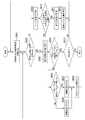
- FIG. 2 is a flowchart showing an example of the operation of the interference evaluation device 1 according to the first embodiment of the present invention.
- the interference evaluation device 1 reads one of the above-mentioned topographical cross-sectional views along the respective radially extending cross-sectional lines (step S001).
- the interference evaluation device 1 analyzes the read topographical cross section and determines whether or not there is a line of sight between the interfering station and the interfering station.
- the interference evaluation device 1 calculates the interference level at the position of the interfering station. (Step S003). The interference evaluation device 1 determines whether or not the calculated interference level is equal to or within a predetermined reference level (for example, whether or not it is within a range of a predetermined reference level).
- the interference evaluation device 1 When the interference level is not equal to the reference level (step S004 / No) and the interference level is lower than the reference level (step S005 / No), the interference evaluation device 1 is half the distance previously moved on the topographical cross section. The position of the interfered station is brought closer to the direction of the interfering station by the distance of (step S006). On the other hand, when the interference level is not equal to the reference level (step S004 / No) and the interference level is higher than the reference level (step S005 / Yes), the interference evaluation device 1 moves the distance earlier on the topographic cross section. The position of the interfered station is moved away from the direction of the interfering station by half the distance of (step S007).
- the interference evaluation device 1 sets the interfering station and the interfered station on the topographical cross section. The position of the interfering station is brought closer to the interfering station in the half position between the two (step S006).
- the interference evaluation device 1 interferes with the interfering station on the topographic cross section. The position of the interfered station is moved away from the direction of the interfering station at a position twice as large as that of the station (step S007).
- the interference evaluation device 1 recalculates the interference level (step 008).
- the interference evaluation device 1 repeats the operations after step S002 and moves the position of the interfered station, so that the interference level becomes a predetermined reference level (for example, within the range of the predetermined reference level). Identify the location.
- the interference evaluation device 1 ridges in the topographical cross section.
- the section between the interfering station and the interfered station is divided at the position (hereinafter referred to as “ridge position”) that becomes (ridge) (step S009).
- the interference evaluation device 1 performs different analysis on each of the divided plurality of sections, and identifies each reference level position.
- the position between the ridge position and the interfering station is a section with a line of sight. Therefore, when the position of the interfered station is a position between the ridge position and the interfering station (step S010 ⁇ Yes), the interference evaluation device 1 performs the same operation as the operation after step S003 described above. On the other hand, a position other than the ridge position and the interfering station is a section with no line of sight.
- the interference evaluation device 1 is used for all the positions in the section (that is, all the delimited meshes). The interference level is calculated for each of the meshes) (step S011). Then, the interference evaluation device 1 specifies the reference level position (step S012).
- the interference evaluation device 1 performs the above-described processing on all the topographical cross-sectional views in order, and ends the operation when the processing on all the topographical cross-sectional views is completed (step S013 ⁇ Yes). This completes the operation of the interference evaluation device 1 shown in the flowchart of FIG.
- FIG. 3 is a diagram showing an example of an interference calculation screen using general-purpose spreadsheet software.
- a plurality of parameter items used for the interference calculation are listed in the left part of the interference calculation screen.
- Each parameter item is classified into one of five categories: "transmitter specifications”, “receiver specifications”, “transmit power structure”, “propagation loss”, and "receiver power structure”. Appropriate values should be set for these listed parameter items according to the specific individual cases of interference evaluation.
- a line design graph showing the calculation result of the interference calculation by a line graph is displayed.
- This line design graph is generated based on the values set for each parameter item listed in the left part of the interference calculation screen.
- the line design graph is based on the values of the parameter items of "interference transmitting side system", "propagation loss / additional loss”, and "interfered receiving side system” in order from the left side to the right side.
- the power value of the transmission power calculated in the above is shown. This represents the transmit power structure.
- the line design graph shows the value of the interference margin in consideration of the interference required I / N with respect to the system noise power.
- the amount of insufficient interference suppression which is the difference between the calculated transmission power value and the interference margin value, is calculated.
- the interference tolerance level I / N described with respect to FIG. 26 regarding the first to fourth embodiments mentioned for comparison in the place where the fifth embodiment described later will be described. (See paragraphs 0213 to 0216).
- the power value of the transmitted power calculated as the calculation result of the interference calculation does not satisfy the value of the interference margin. That is, the allowable interference power amount of the interfered station exceeds the influence of the interference received from the interfered station. As a result, it is determined that the interfering station and the interfering station cannot be used (shared) at the same time. As a result, on the interference calculation screen shown in FIG. 3, an "x" mark indicating that sharing is impossible is displayed in the display column of the "determination result" item.
- FIG. 4 is a diagram showing another example of an interference calculation screen using general-purpose spreadsheet software. As shown in the figure, a plurality of parameter items used for the interference calculation are listed in the left part of the interference calculation screen. Each parameter item is classified into one of four categories: "transmitter specifications”, “receiver specifications”, “propagation loss”, and “receiver power structure”. Appropriate values should be set for these listed parameter items according to the specific individual cases of interference evaluation.
- FIG. 4 illustrates an interference calculation screen in a case where an unnecessary wave radiated by an electric appliance or the like is regarded as an interference wave and a line is designed.
- the transmission power density of the radiated unwanted wave is used as the parameter item of the "source specifications" for the interference calculation.
- a line design graph is displayed as in FIG.
- the noise power on the transmitting side is smaller than the allowable interference power on the receiving side as the calculation result of the interference calculation. That is, the receiving side can tolerate the influence of interference from the transmitting side.
- a “ ⁇ ” mark indicating that sharing is possible is displayed in the display column of the “determination result” item.
- interference evaluation include, for example, interference evaluation of a transmitting station and a receiving station on the ground, and interference evaluation of a satellite and a wireless device on the ground.
- interference transmitting side system As described above, in the calculation of the interference level, for example, various parameters as shown on the left side of the interference calculation screen in FIG. 3 are used. These parameters are, for example, as shown in the legend column on the right side of the interference calculation screen of FIG. 3, "interference transmitting side system”, “propagation loss / additional loss”, “interfered receiving side system”, “interfered receiving side system”. It is classified into “margin” and "system noise power”. For example, in the operation of the interference evaluation device 1 shown in FIG.
- the interference calculation screen By operating the interference calculation screen on the spreadsheet software as described above, for example, by operating the operator, between the interfering station and the interfering station in each direction of the plurality of cross-sectional lines drawn radially.
- the reference level position is specified for each of the cases where there is a line of sight and the case where there is no line of sight.
- FIG. 5 is a diagram showing an example of analysis of a topographic cross section when there is no line of sight (with a ridge).
- the interference evaluation device 1 When the interference evaluation device 1 has a ridge in the section between the interfering station and the interfered station for which the interference level is calculated in the read topographic cross section, there is no line of sight in the section. Judge that there is. This corresponds to the case of step S002 ⁇ Yes in the flowchart shown in FIG. Then, the interference evaluation device 1 divides the target section into a section without line-of-sight and a section with line-of-sight at the ridge position on the topographical cross-sectional view (FIG. 2, step S009), and the line-of-sight is displayed for each divided section. The interference level is calculated by a method according to the presence or absence (FIG. 2, step S003 or step S011).
- FIG. 6 is a diagram showing an example of analysis of a topographic cross section when there is a line of sight (no ridge).
- the interference evaluation device 1 does not have a ridge in the section between the interfering station and the interfered station for which the interference level is calculated in the read topographical cross section, the interfering station and the interfering station It is judged that there is a prospect in all the sections in between. This corresponds to the case of steps S002 and No in the flowchart shown in FIG. Then, the interference evaluation device 1 calculates the interference level for the position of an arbitrary interfered station.
- the interference evaluation device 1 compares the calculated interference level with a predetermined reference level. Then, when the calculated interference level is higher than the reference level on the topographical cross section, the interference evaluation device 1 moves the position of the interfered station closer to the interfering station, and the calculated interference level is calculated. If it is lower than the reference level, move the position of the interfered station away from the interfering station. By repeating the above process, the interference evaluation device 1 specifies the reference level position for each read topographic cross section.
- FIG. 7 is a diagram showing an example of a position specifying procedure when there is a line of sight by the interference evaluation device 1 according to the first embodiment of the present invention.
- the interference evaluation device 1 moves the position of the interfered station on the topographical cross section according to the calculated height of the interference level, and the interference level becomes equal to the reference level at the reference level position. To identify.
- the operation of the interference evaluation device 1 described below corresponds to the operation of steps S004 to S008 of the flowchart shown in FIG.
- the interference evaluation device 1 first calculates the interference level at the initial position (1), which is an arbitrary position, on the topographical cross-sectional view, and compares the calculated interference level with the reference level. When the interference level is lower than the reference level, the interference evaluation device 1 sets the position of the interfered station to the interfered station so that the distance between the position of the interfered station and the position of the interfered station is halved. Move closer to the position of. That is, the interference evaluation device 1 moves the position of the interfered station to a position (position (2) in FIG. 7) between the position of the interfering station and the initial position (1).
- the interference evaluation device 1 calculates the interference level at the position (2) on the topographic cross section, and compares the calculated interference level with the reference level.
- the interference evaluation device 1 moves the position of the interfered station away from the position of the interfering station by half the length of the previously moved distance. That is, the interference evaluation device 1 moves the position of the interfered station to a position (position (3) in FIG. 7) between the initial position (1) and the position (2).
- the interference evaluation device 1 calculates the interference level at the position (3) on the topographical cross section, and compares the calculated interference level with the reference level.
- the interference evaluation device 1 moves the position of the interfered station away from the position of the interfering station by half the length of the previously moved distance. That is, the interference evaluation device 1 moves the position of the interfered station to a position (position (4) in FIG. 7) between the initial position (1) and the position (3).
- the interference evaluation device 1 calculates the interference level at the position (4) on the topographical cross section, and compares the calculated interference level with the reference level.
- the interference evaluation device 1 brings the position of the interfered station closer to the position of the interfering station by half the length of the previously moved distance. That is, the interference evaluation device 1 moves the position of the interfered station to a position (position (5) in FIG. 7) between the positions (3) and (4).
- the interference evaluation device 1 calculates the interference level at the position (5) on the topographic cross section, and compares the calculated interference level with the reference level.
- the interference evaluation device 1 specifies the position (5) as the reference level position.
- the interference evaluation device 1 performs the above operation for all the read topographical cross-sectional views.
- the interference evaluation device 1 performs the above operation to calculate the interference level for all the meshes of the map divided into meshes, and the reference level is smaller than that of the conventional method.
- the position can be specified.
- FIG. 8 is a diagram showing an example of a position specifying procedure when there is no line of sight by the interference evaluation device 1 according to the first embodiment of the present invention.
- FIG. 8 shows the topographical cross-sectional view shown in FIG. 8, when the interfered station is viewed from the position of the interfering station, there are a section with a line of sight and a section without a line of sight depending on the position of the interfered station. This is because the terrain has undulations, and depending on the position of the interfered station, the line of sight of the interfered station from the position of the interfering station may or may not be blocked by the undulations. ..
- the interference evaluation device 1 first calculates the interference level at the initial position, which is the position of the section without line of sight, on the topographical cross section. In this case, the interference evaluation device 1 compares the calculated interference level with the reference level, and when the interference level is lower than the reference level, the interference evaluation device 1 moves the position of the interfered station to the ridge position.
- the interference evaluation device 1 sets the distance between the interfering station and the interfered station to be twice the distance between the interfering station and the initial position. Move the position of the interfered station away from the position of the interfering station. However, in this case, the position of the interfered station after movement may be within the section with a line of sight. Therefore, it is necessary to move the position of the interfered station to the boundary between the section without line of sight and the section with line of sight.
- the interference level was calculated for all the meshes of the map divided into meshes within the range without visibility. Even so, it is considered that the amount of calculation will not be extremely increased.
- the interference evaluation device 1 sets the interference level to the reference level according to the position identification procedure in the case where there is a line of sight described above with reference to FIG. Identify a reference level position that is equal to.
- FIG. 9 is a diagram showing an example of an initial position setting procedure in position identification by the interference evaluation device 1 according to the first embodiment of the present invention.
- the interference evaluation device 1 sets the initial position using the result of the previous interference evaluation when performing the interference evaluation on the next topographical cross section after performing the interference evaluation on a certain topographical cross section.
- the reference level position specified by the interference evaluation performed on the topographical cross section where the interference evaluation device 1 is located is set as the position P10.
- the interference evaluation device 1 sets the initial position when performing interference evaluation on the next topographical cross section at the position P11 which is equidistant from the interference station to the position P10. That is, the interference evaluation device 1 determines the position P11, which is the intersection of the circle including the position P10 with the interfering station as the center of the circle and the adjacent cross-sectional lines extending radially, for the interference evaluation with respect to the next topographical cross section.
- the initial position is the intersection of the circle including the position P10 with the interfering station as the center of the circle and the adjacent cross-sectional lines extending radially, for the interference evaluation with respect to the next topographical cross section.
- the interference evaluation device 1 performs interference evaluation with the position P11 as the initial position, and specifies the reference level position.
- the specified reference level position is defined as the position P12 shown in FIG.
- the interference evaluation device 1 sets the initial position when performing interference evaluation on the next topographical cross section at the position P13 which is equidistant from the interference station to P12.
- a boundary line consisting of a set of specified reference level positions including the position P10 and the position P12 is drawn.
- This boundary line is a boundary line indicating whether or not it is acceptable under the influence of interference. That is, the outside of the boundary line is an allowable area where the influence of interference can be tolerated. On the other hand, the inside of the boundary line is an unacceptable area where the influence of interference is unacceptable.
- the operation of the interference evaluation device 1 regarding the setting of the initial position corresponds to the operation of step S003 in specifying the reference level position when there is a line of sight in the flowchart shown in FIG.
- the respective reference level positions in both topographical cross-sections along adjacent radially extending cross-sectional lines often exist relatively close to each other. Therefore, as described above, the position equidistant from the distance between the reference level position and the position of the interfering station specified by the interference evaluation with respect to the previous topographic cross section is set to the next (adjacent radial cross section).
- the search can be started from a position relatively close to the reference level position to be specified.
- the interference evaluation device 1 can specify the reference level position with a smaller amount of calculation.
- the interference evaluation device 1 when the interference evaluation device 1 has a ridge in the section between the interfering station and the interfered station to be subjected to the interference level calculation in the read topographical cross section, the interference evaluation device 1 is in the section. Determines that there is a section with no line of sight. Then, the interference evaluation device 1 divides the section into a section with no line-of-sight and a section with line-of-sight at the ridge position on the topographic cross-sectional view, and each divided section has an interference level according to the presence or absence of line-of-sight. To calculate.
- an example of a procedure for discriminating between a section with a line of sight from the interfering station and a section without a line of sight, which is performed by the interference evaluation device 1 will be described.
- FIG. 10 is a diagram showing an example of a procedure for determining the presence or absence of visibility by the interference evaluation device 1 according to the first embodiment of the present invention.
- the interference evaluation device 1 draws a straight line (hereinafter, referred to as “line-of-sight straight line”) connecting the position of the interfering station and the position of the interfered station in the topographical cross-sectional view.
- line-of-sight straight line is not in contact with the topographic line in the topographical cross section
- the interference evaluation device 1 determines that the position of the interfered station is within the section with line-of-sight.
- the "terrain line” referred to here is a line representing the position of the ground surface in the topographical cross section.
- the "ground surface” here includes the surface of an object existing on the ground surface such as a building or a tree.
- the interference evaluation device 1 determines that the position of the interfered station is within the section without line-of-sight.
- the position where the line of sight and the terrain line meet corresponds to the ridge position described above.
- the topographical cross section illustrated in FIG. 10 is divided into a section with a line of sight (A), a section without a line of sight (B), and a section with a line of sight (C).
- the reference level is only one interference level, but a plurality of reference levels having different stages may be used. For example, a reference level set to a higher interference level, a reference level set to a medium interference level, a reference level set to a lower interference level, and the like may be used.
- FIG. 11 is a diagram showing an example of an initial position setting procedure in position identification by the interference evaluation device 1 according to the first embodiment of the present invention.
- the reference level position of one reference level indicating an acceptable interference level is specified on the topographical cross section along each radially extending cross section.
- the reference level positions of the plurality of (three) reference levels having different stages are specified on the topographical cross-sectional view along the respective radially extending cross-sectional lines.
- the inside of the boundary line based on the reference level position of the high reference level is the region where the interference level is high, and the inside of the boundary line based on the reference level position of the medium reference level and the reference of the high reference level.
- the inside of the boundary line based on the level position is the region where the interference level is medium, the inside of the boundary line based on the reference level position of the low reference level, and the inside of the boundary line based on the reference level position of the medium reference level. Is a region where the interference level is low, and outside the boundary line based on the reference level position of the low reference level is a region where the interference level is slightly affected by interference (or is not affected by interference).
- the reference level position of the low reference level identified by the interference evaluation performed on the topographical cross section with the interference evaluation device 1 is defined as the position P20.
- the interference evaluation device 1 sets the initial position when performing interference evaluation on the next topographical cross section at the position P21 which is equidistant from the distance from the interfering station to the position P20. That is, the interference evaluation device 1 evaluates the interference with respect to the next topographical cross-sectional view at the position P21 which is the intersection of the circle including the position P20 with the interfering station as the center of the circle and the adjacent cross-sectional lines extending radially. The initial position.
- the interference evaluation device 1 performs interference evaluation with the position P21 as the initial position, and identifies the reference level position of the low reference level.
- the specified low reference level reference level position is defined as the position P22 shown in FIG.
- the interference evaluation device 1 sets the initial position when performing interference evaluation on the next topographical cross section at the position P23 which is equidistant from the distance from the interfering station to the position P22.
- the interference evaluation device 1 performs interference evaluation with the position P23 as the initial position.
- the interference evaluation device 1 starts the calculation of the interference level from the position P23 which is the initial position, and identifies the reference level position of the low reference level.
- the interference evaluation device 1 obtains the value of the interference level at the position P24, the position P25, etc. shown in FIG. 11, for example.
- the interference evaluation device 1 records the values of these interference levels obtained in the process of interference evaluation. Then, the interference evaluation device 1 utilizes the recorded interference level value for specifying the reference level position of the medium reference level or the reference level position of the high reference level.
- the interference evaluation device 1 obtains an initial position when specifying a reference level position of a medium reference level in the process of identifying a reference level position of a low reference level with respect to a topographical cross section beyond the interference station.
- the position is set to P24.
- the interference evaluation device 1 records, for example, the value of the interference level obtained each time the position of the interfered station is moved in the process of identifying the outermost (that is, the lower reference level) reference level position. Keep it. Then, the interference evaluation device 1 is desired among the above-described recorded interference level values, for example, when identifying an inner (that is, a medium reference level or a high reference level) reference level position. The position where the value closest to the reference level value of is obtained is set as the initial position. As a result, the interference evaluation device 1 can obtain the evaluation result of the desired surface interference evaluation with a smaller amount of calculation (that is, specify the range based on the above three boundaries with a smaller amount of calculation). can do).
- FIG. 12 is a diagram for explaining a comparison between the interference evaluation according to the first embodiment of the present invention and the interference evaluation by the prior art.
- FIG. 12 lists three interference evaluation methods.
- One is the interference evaluation method by the interference evaluation device 1 according to the present embodiment described above.
- the remaining two are interference evaluation methods according to the prior art.
- One of them is an interference evaluation method (hereinafter referred to as "conventional technique A") for calculating the interference level for all the meshes of the map divided into meshes.
- an interference evaluation method that calculates the interference level for all the meshes after adjusting the number of meshes of the map divided into meshes to be less than 100 [pieces] x 100 [pieces] in the vertical direction (hereinafter referred to as the interference evaluation method).
- Convention technology B is an interference evaluation method for calculating the interference level for all the meshes after adjusting the number of meshes of the map divided into meshes to be less than 100 [pieces] x 100 [pieces] in the vertical direction.
- N is the number of positions to be evaluated for interference evaluation.
- the wider the target range of the interference evaluation on the map the larger the size of each mesh of the mesh.
- the accuracy of the calculation result of the interference level decreases in inverse proportion to the size.
- the interference evaluation device 1 extends in all directions (360 °) around the position of the interfering station (or the interfering station) as described above. Each reference level position is identified based on the terrain along each radial section. Then, the interference evaluation device 1 evaluates the surface interference evaluation based on the specified reference level position, and obtains the range affected by the interference.
- the calculation amount of the interference evaluation by the interference evaluation device 1 according to the present embodiment can be represented by 360 ⁇ (1 / ⁇ ) ⁇ k.
- ⁇ represents the angle between two adjacent radial cross-sectional lines.
- k represents the number of times until the reference level position is specified by the interference evaluation device 1 dividing the section between the interfering station and the interfered station into two in the topographical cross section.
- FIG. 13 is a diagram for explaining the correspondence between the position of the mesh of the mesh and the position of the cross-sectional line extending radially.
- N 1,000
- the angle between two adjacent cross-sectional lines extending radially is about ⁇ 0.1 [°].
- the section between the interfering station and the interfered station is divided into two.
- the number of times the interference level is calculated to specify the reference level position is 9 times or less (k ⁇ 9).
- the interference evaluation device 1 can significantly reduce the amount of calculation to 3% of the conventional one.
- the section between the interfering station and the interfered station is defined.
- the number of times of calculation of the interference level performed to specify the reference level position while 2 minutes is 13 times or less (k ⁇ 13).
- the interference evaluation device 1 can significantly reduce the amount of calculation to 0.5% of the conventional amount.
- the interference evaluation device 1 can significantly reduce the amount of calculation while suppressing the deterioration of the evaluation accuracy.
- the above-mentioned prior art B can be relatively easily implemented as interference calculation software (interference calculation tool).
- the prior art A is not a realistic interference evaluation method because the amount of calculation is enormous.
- FIG. 14 is a schematic view showing an overall outline of the function of the interference evaluation device 1 according to the embodiment of the present invention.
- the main function of the interference evaluation device 1 is a station information DB management function that stores and manages a plurality of interfering station information and a plurality of interfered station information in a database (hereinafter referred to as "DB").
- the interfering station information includes information indicating transmission power, frequency and bandwidth, antenna gain, filter characteristics, and the like.
- the interfered station information includes information indicating frequency and bandwidth, antenna gain and filter characteristics, allowable interference power, and the like.
- Another main function of the interference evaluation device 1 is a propagation loss calculation function that calculates the propagation loss from the interfering station information and the interfered station information by the propagation loss calculation software or the calculation model.
- Propagation loss software is software that calculates propagation loss using map information.
- the calculation model is a model for calculating the propagation loss from the propagation loss calculation formula.
- a pass / fail determination function for determining whether or not the interfering station and the interfered station can be shared based on the calculation result by the propagation loss calculation function, or a propagation loss calculation.
- a received signal strength output function that outputs information indicating the received signal strength calculated based on the calculation result of the function.
- the interference evaluation device 1 there is a GUI (Graphical User Interface) display function that displays a display screen that visually represents information used or generated by each of the above-mentioned functions.
- GUI Graphic User Interface
- the interfering station information and the interfering station information stored in the DB by the station information DB management function are selected.
- Desired interfering station information and interfering station information are displayed in a selectable manner.
- the propagation loss calculation function uses the selected interfering station information and interfering station information for propagation loss calculation.
- each display screen displayed by the GUI display function may have a guidance (advice, comment) display function for displaying guidance (or advice or comment) to the user.
- Guidance or advice or comments
- FIG. 15 is a block diagram showing a functional configuration of the interference evaluation device 1 according to the embodiment of the present invention.
- the interference evaluation device 1 plane-wise causes radio wave interference that occurs between the first radio station (interfering station or interfering station) and the second radio station (interfering station or interfering station). It is a device for evaluation.
- the interference evaluation device 1 includes a control unit 10, an input setting / selection / registration change instruction unit 11, an interference method (menu) selection unit 12, and a station information input / registration unit 13. • Interfered station selection unit 14, history selection unit 15, at least one calculation condition setting unit 16, at least one calculation result display designation unit 17, interference power calculation / pass / fail determination unit 18, and calculation result diagram. A display unit 19, a storage unit 20, and an input / output unit 30 are included.
- the interference evaluation device 1 includes an information processing device (for example, a general-purpose computer such as a personal computer or a small information terminal such as a tablet terminal).
- an information processing device for example, a general-purpose computer such as a personal computer or a small information terminal such as a tablet terminal.
- the control unit 10 controls the processing executed by each functional block of the interference evaluation device 1.
- the control unit 10 includes a processor (for example, a CPU (Central Processing Unit)).
- the storage unit 20 includes a station DB 201, a history storage unit 202, and a map information DB 203.
- the storage unit 20 includes a storage medium (for example, a magnetic disk, a semiconductor memory, or a combination of these storage media).
- the input / output unit 30 includes an operation input unit 301 and a display unit 302.
- the operation input unit 301 includes an input member (for example, a keyboard, a mouse, etc.) that receives an operation input by the user.
- the display unit 302 includes an output member (for example, a liquid crystal display) that displays a display screen presented to the user.
- the operation input unit 301 and the display unit 302 may be composed of one member (for example, a touch panel) having an input / output function.
- One calculation condition setting unit 16, at least one calculation result display designation unit 17, interference power calculation / pass / fail judgment unit 18, and calculation result diagram display unit 19 are provided by a software program executed by the control unit 10. It may be a function to be implemented. In this case, for example, this software program is stored in the storage unit 20, read by the control unit 10, and executed.
- the input setting / selection / registration change instruction unit 11 acquires the information input from the operation input unit 301 by the operation input by the user.
- the input setting / selection / registration change instruction unit 11 converts the instruction into an instruction indicating input setting / selection / registration change, etc., which can be recognized by each function block of the interference evaluation device 1, and outputs the instruction to each function block.
- the input setting / selection / registration change instruction unit 11 inputs, for example, an electric signal input from the operation input unit 301 to a software program constituting each functional block of the interference evaluation device 1. Convert to input data.
- the map information DB 203 is a database that stores map information.
- the map information referred to here is, for example, information indicating an altitude for each position (for example, latitude and longitude) and an existing object (for example, a building, a road, a river, etc.).
- the map information DB 203 is used to display the position of the radio station subject to the interference evaluation, the interference evaluation result, and the like on the map.
- map information DB 203 stores information indicating a topographical cross section in each direction centered on the first radio station (interfering station or interfered station).
- the calculation result display designation unit 17 displays the calculation result in the interference evaluation and the like on the map displayed on the display unit 302. Specify whether to display.
- the figure display unit 19 of the calculation result displays the evaluation result of the interference evaluation on the map displayed on the display unit 302 based on the designation by the calculation result display designation unit 17.
- the history storage unit 202 accumulates information (hereinafter, also referred to as "history information") indicating calculation conditions and evaluation results at the time of interference evaluation for a radio station that has been subject to interference evaluation in the past.
- the history information stored in the history storage unit 202 is utilized in a new interference evaluation.
- the history selection unit 15 determines how to select and utilize the history information stored in the history storage unit 202 based on the instruction information input from the operation input unit 301, which indicates an instruction from the user. Is specified.
- the station DB201 (station information storage unit) is a database composed of information on radio stations subject to interference evaluation.
- the giving / interfering station selection unit 14 (station information selection unit) outputs information about a radio station stored in the station DB 201 based on the instruction information input from the operation input unit 301, which indicates an instruction from the user. Select and use for interference evaluation.
- the station information input / registration unit 13 inputs information about the radio station to the station DB 201 and registers it based on the instruction information input from the operation input unit 301, which indicates an instruction from the user.
- the interference method (menu) selection unit 12 determines what kind of interference evaluation is to be performed based on the instruction information input from the operation input unit 301, which indicates an instruction from the user.
- the calculation condition setting unit 16 sets the calculation conditions for the interference evaluation in the interferometry selected by the interferometry (menu) selection unit 12.
- the calculation condition setting unit 16 can set the calculation condition of the interference evaluation by using the information about the radio station selected by the giving / interfering station selection unit 14.
- the above-mentioned selection of radio station information and setting of calculation conditions for interference evaluation are performed via the input setting / selection / registration change instruction unit 11.
- the calculation condition setting unit 16 (discrimination unit) acquires the information stored in the map information DB 203 indicating the topographical cross section in each direction centered on the first radio station (interfering station or interfered station). .. Then, the calculation condition setting unit 16 displays the topographical cross section based on the acquired topographical cross section in a section where there is a line of sight from the position of the first radio station (interfering station or interfered station) and the first radio station (interfering). It is determined that the section has no line of sight from the position of the station or the interfered station), and the determined result is set as the calculation condition for the interference evaluation.
- the calculation condition setting unit 16 discrimination unit of the first radio station (interfering station or interfered station) is based on the position of the ridge (ridge) included in the topographical cross section based on the acquired topographical cross section. Determine the section with no line of sight from the position.
- the interference power calculation / pass / fail judgment unit 18 calculates the interference power and makes a pass / fail judgment.
- the interference power calculation / pass / fail determination unit 18 selects input settings / selection / registration change instructions after the calculation condition setting unit 16 selects information about the radio station to be evaluated and sets the interference evaluation calculation conditions. When an instruction to execute the calculation is given via the unit 11, the interference power calculation / pass / fail determination unit 18 executes the calculation of the interference power.
- the interference power calculation / pass / fail determination unit 18 makes a pass / fail determination by comparing the value of the interference power based on the execution result of the calculation of the interference power with the value at which interference is acceptable.
- the pass / fail judgment referred to here is a judgment indicating whether or not the interfering station, which is the radio station to be evaluated, and the interfered station affected by the interfering station can be shared.
- the interference power calculation / pass / fail determination unit 18 is the first radio for the section determined to have a line of sight from the position of the first radio station (interfering station or interfered station).
- the interference power calculation / pass / fail determination unit 18 (specific unit) has a mesh pattern (mesh) for the section determined to have no line of sight from the position of the first radio station (interfering station or interfered station). By evaluating the radio wave interference for each mesh of the evaluation target area divided into the shape), the position (reference level position) at which the desired interference amount (interference level) is obtained is specified.
- the interference power calculation / pass / fail determination unit 18 (specific unit) has a position (reference level position) and a first position (reference level position) at which the desired interference amount (interference level) specified in the evaluation of radio wave interference with respect to the first terrain cross section is obtained.
- the position equal to the distance between the radio station (interfering station or interfered station) is set as the initial position of the position search in the evaluation of radio wave interference with respect to the second terrain cross section adjacent to the first terrain cross section. ..
- the interference power calculation / pass / fail determination unit 18 (specific unit) evaluates the radio wave interference with respect to the second terrain cross section by starting the search from the initial position.
- the calculation result display designation unit 17 stores the information indicating the calculation result of the interference evaluation output from the interference power calculation / pass / fail determination unit 18 in the history storage unit 202, or displays it on the display unit 302 as described above. It is displayed on the map to be displayed.
- a plurality of calculation condition setting units 16 and calculation result display designation units 17 may exist.
- the plurality of calculation condition setting units 16 and the plurality of calculation result display designation units 17 have partially different functions from each other.
- the plurality of calculation condition setting units 16 and the plurality of calculation result display designation units 17 are selected and used, respectively, according to the type of interference evaluation based on the instruction information input from the operation input unit 301, which indicates an instruction from the user. Be done.
- function outline the outline of the function of the interference evaluation device 1 described with reference to FIG. 14
- functional configuration the functional configuration of the interference evaluation device 1 described with reference to FIG. 15
- the station information DB management function that stores and manages a plurality of interfering station information and a plurality of interfered station information in the above-mentioned function outline is the station information input / registration unit 13 and the giving / interfering / interfering station information in the above-mentioned functional configuration. Corresponds to the interfered station selection unit 14.
- the propagation loss calculation function for calculating the propagation loss from the interfering station information and the interfered station information by the propagation loss calculation software or the calculation model in the above-mentioned functional outline is the at least one calculation condition in the above-mentioned functional configuration. It corresponds to a part of the setting unit 16 and the interference power calculation / pass / fail determination unit 18.
- the pass / fail judgment function in the above-mentioned function outline (which determines whether or not the interfering station and the interfered station can be shared based on the calculation result by the propagation loss calculation function) is the interference in the above-mentioned functional configuration. It corresponds to a result display function by a part of the power calculation / pass / fail determination unit 18 and the calculation result display designation unit 17.
- the received signal strength output function (which outputs information indicating the received signal strength calculated by the calculation result by the propagation loss calculation function) in the above-mentioned function outline is the interference power calculation / pass / fail judgment unit in the above-mentioned functional configuration. It corresponds to a part of 18 and the result display function by the calculation result display designation unit 17.
- the interference evaluation device 1 is an interference evaluation device that surface-wise evaluates radio wave interference generated between a first radio station and a second radio station. is there.
- the interference evaluation device 1 acquires information indicating a terrain cross section in each direction centered on the first radio station, and obtains the terrain cross section from a section having a line of sight from the position of the first radio station and the first.
- the calculation condition setting unit 16 discrimination unit for discriminating between the positions of the radio stations and the sections where there is no line of sight is provided. Further, the interference evaluation device 1 is based on the distance between the first radio station and the second radio station for a section determined to have a line of sight from the position of the first radio station.
- the position (reference level position) where the desired amount of interference is obtained is specified, and the section determined to have no line of sight from the position of the first radio station is divided into meshes for each mesh of the evaluation target area.
- An interference power calculation / pass / fail determination unit 18 (specific unit) for specifying a position (reference level position) at which the desired amount of interference is obtained by evaluating the radio wave interference is provided.
- the interference evaluation device 1 can reduce the amount of calculation while maintaining the accuracy of interference evaluation.
- FIG. 16 is a diagram for explaining the correspondence between the position of the mesh of the mesh and the position of the cross-sectional line extending radially. Note that FIG. 16 shows a region cut out from the upper right quarter of the target range of the interference evaluation centered on the position of the interfering station, as shown in FIG. 13, for example. is there.
- the cross-sectional lines extending radially and the mesh of the mesh have a one-to-one correspondence with each other.
- a plurality of radial cross-sectional lines overlap with one mesh. This means that the calculation of the interference level at the same position (mesh) may be performed twice. In order to avoid such duplication, in the second embodiment described below, the closer the region is to the center of the target range, the more the calculation of the interference level is omitted.
- the number of meshes of the mesh is N / 2 in each of the vertical and horizontal directions.
- the position of the lower left corner of the region (that is, the position of the center of the target range) is the position of the interfering station.
- the upper outer edge portion and the right outer edge portion of the region are the outer edge portions of the target range of the interference evaluation.
- the interference evaluation device 1 assigns a number (hereinafter, referred to as "direction number") to each of the above-mentioned radially extending cross-sectional lines used in this interference evaluation. That is, as shown in FIG. 16, for example, the interference evaluation device 1 assigns a direction number of "No. 1" to a cross-sectional line extending radially in the direction of the mesh in the lower right corner. While assigning direction numbers in order, the direction numbers are assigned up to the cross-sectional line extending in the direction of the mesh in the upper right corner. In this case, the direction number given to the cross-sectional line extending in the direction of the mesh in the upper right corner is "No. N / 2". Further, the interference evaluation device 1 assigns direction numbers in order from the cross-sectional line extending in the direction of the mesh in the upper right corner to the cross-sectional line extending in the direction of the mesh in the upper left corner.
- the direction numbers assigned are "No. 1" (direction of the lower right corner), "No. 2", “No. 3", in order from the line extending in the direction of the mesh in the lower right corner.
- approximately two radially extending cross-sectional lines correspond to one mesh.
- one mesh corresponds to the cross-sectional line to which the direction number of "No. 1" is assigned and the cross-sectional line to which the direction number of "No. 2" is assigned, and the direction number of "No. 3" is assigned.
- One mesh corresponds to the cross-sectional line to which is given and the cross-sectional line to which the direction number of "No. 4" is given.
- one mesh corresponds to the cross-sectional line assigned the direction number of "No. N / 2-3" and the cross-sectional line assigned the direction number of "No. N / 2-2".
- One mesh corresponds to the cross-sectional line to which the direction number of "No. N / 2-1" is given and the cross-sectional line to which the direction number of "No. N / 2" is given.
- the cross-sectional lines extending radially and the mesh have a 2: 1 correspondence.
- the interference evaluation device 1 according to the present embodiment has a cross-sectional line extending radially with an odd number of direction numbers for such a position near the middle between the outer edge of the target range and the center of the target range.
- the interference level is calculated only when the interference evaluation is performed.
- the interference evaluation device 1 omits the calculation of the interference level when performing the interference evaluation on the radially extending cross-sectional lines with even-numbered direction numbers. Then, the interference evaluation device 1 uses the value of the interference level calculated in the interference evaluation for the radially extending cross-sectional lines to which the odd-numbered direction numbers are assigned. As a result, the interference evaluation device 1 according to the present embodiment can omit the calculation of the interference level of about half at the position near the middle between the outer edge portion of the target range and the center of the target range.
- the operation of the interference evaluation device 1 when the direction number is an odd number and the operation of the interference evaluation device 1 when the direction number is an even number may be opposite. That is, the interference evaluation device 1 may be configured to calculate the interference level when the direction number is an even number and omit the calculation of the interference level when the direction number is an odd number.
- one mesh corresponds to a cross-sectional line assigned direction numbers of "No. 1", “No. 2", “No. 3", and “No. 4", and "No. N / One mesh corresponds to the cross-section lines given the direction numbers of "2-3", “No. N / 2-2", “No. N / 2-1", and "No. N / 2". are doing.
- the cross-sectional lines extending radially and the mesh correspond to 4: 1.
- the interference evaluation device 1 is assigned a direction number such that the remainder when multiplied by 4 is 1 for the periphery of such a position that is a distance of about 1/4 from the center of the target range.
- the interference level is calculated only when the interference evaluation is performed on the radially extending cross-sectional lines.
- the interference evaluation device 1 omits the calculation of the interference level when performing the interference evaluation on the radially extending cross-sectional line to which the remainder when multiplied by 4 is not 1. Then, the interference evaluation device 1 uses the value of the interference level calculated in the interference evaluation for the radially extending cross-sectional line to which the direction number in which the remainder when multiplied by 4 is 1 is given. As a result, the interference evaluation device 1 according to the present embodiment omits the calculation of the interference level of about 3/4 around the position where the distance is about 1/4 from the center of the target range (to the outer edge). Can be done.
- FIG. 17 is a flowchart showing an example of the operation of the interference evaluation device 1 according to the second embodiment of the present invention.
- the flowchart shown in FIG. 17 is different from the flowchart shown in FIG. 2 (first embodiment) in that the operation of step S102 and the operation of step S108 are added.
- step S101 corresponds to step S001 and performs the same function and operation.
- step S103 corresponds to step S002
- step S104 corresponds to step S003.
- step S105 corresponds to step S004
- step S106 corresponds to step S005
- step S107 corresponds to step S006,
- step S110 corresponds to step S008.
- step S111 corresponds to step S009
- step S112 corresponds to step S010
- step S113 corresponds to step S011
- step S114 corresponds to step S012
- step S115 corresponds to step S013.
- the interference evaluation device 1 reads one of the above-mentioned topographical cross-sectional views along the respective radially extending cross-sectional lines (step S101).
- the interference evaluation device 1 assigns a number to the read radially extending cross-sectional line (step S102).
- the interference evaluation device 1 analyzes the read topographical cross section and determines whether or not there is a line-of-sight between the interfering station and the interfered station (step S103).
- the interference evaluation device 1 calculates the interference level at the position of the interfering station. (Step S104). The interference evaluation device 1 determines whether or not the calculated interference level is equal to or within a predetermined reference level (for example, whether or not it is within a range of a predetermined reference level).
- the interference evaluation device 1 When the interference level is not equal to the reference level (step S105 / No) and the interference level is lower than the reference level (step S106 / No), the interference evaluation device 1 is half the distance previously moved on the topographical cross section. The position of the interfered station is brought closer to the direction of the interfering station by the distance of (step S107). The interference evaluation device 1 determines whether or not the calculation of the interference level is necessary (that is, whether or not the calculation of the interference level can be omitted) based on the direction number assigned to the radially extending cross-sectional line. (Step S108).
- the interference evaluation device 1 When it is determined that the interference level calculation is necessary (step S108 ⁇ Yes), the interference evaluation device 1 continues the interference evaluation. On the other hand, when it is determined by this determination that the calculation of the interference level is unnecessary (steps S108 and No), the interference evaluation device 1 refers to the next topographical cross section (along the adjacent radially extending cross-sectional lines). Move to interference evaluation.
- the interference evaluation device 1 moves the distance earlier on the topographical cross-sectional view. The position of the interfering station is moved away from the direction of the interfering station by half the distance of (step S109).
- the interference evaluation device 1 recalculates the interference level (step 110).
- the interference evaluation device 1 repeats the operations of step S103 and subsequent steps to move the position of the interfered station, so that the interference level becomes a predetermined reference level (for example, within the range of the predetermined reference level). Identify the location.
- the interference evaluation device 1 ridges in the topographical cross section. At the position, the section between the interfering station and the interfering station is divided (step S111). Then, the interference evaluation device 1 performs different analysis on each of the divided plurality of sections, and identifies each reference level position.
- the position between the ridge position and the interfering station is a section with a line of sight. Therefore, when the position of the interfered station is a position between the ridge position and the interfering station (step S112 ⁇ Yes), the interference evaluation device 1 performs the same operation as the operation after step S104 described above. On the other hand, a position other than the ridge position and the interfering station is a section with no line of sight. When the position of the interfered station is not between the ridge position and the interfering station (step S112 ⁇ No), the interference evaluation device 1 is used at all positions in the section (that is, all the delimited meshes). The interference level is calculated for each of the meshes) (step S113). Then, the interference evaluation device 1 specifies the reference level position (step S114).
- the interference evaluation device 1 performs the above-described processing on all the topographical cross-sectional views in order, and ends the operation when the processing on all the topographical cross-sectional views is completed (step S115 ⁇ Yes). This completes the operation of the interference evaluation device 1 shown in the flowchart of FIG.
- the interference evaluation device 1 determines the interfered station to the position of half the distance from the interfered station to the interfered station by calculating the initial interference level for a certain topographical rail.
- the interference evaluation is continued.
- the direction numbers are even, the calculation of the interference level is omitted, and the process proceeds to the interference evaluation for the next topographical cross section (along the adjacent radial cross-section lines).
- the interference evaluation is continued in the above, and the interference evaluation device 1 interferes with the interfered station to a position of 1/4 of the distance from the interfered station to the interfered station by the second calculation of the interference level.
- the interference evaluation is continued in the above, and the interference evaluation device 1 interferes with the interfered station to a position of 1/4 of the distance from the interfered station to the interfered station by the second calculation of the interference level.
- the interference evaluation is continued in the above, and the interference evaluation device 1 gives the interfered station to the position of 1/ 2n of the distance from the interfered station to the interfered station by the calculation of the interference level nth time.
- the remainder obtained by multiplying the direction number given to the radially extending cross-sectional line that is the target of the interference evaluation by 2 n is 1.
- the remainder obtained by multiplying the direction number by 2 n is not 1, the calculation of the interference level is omitted, and the process proceeds to the interference evaluation for the next topographical cross section (along the adjacent radial cross-section lines).
- the interference evaluation device 1 As described above, by adding the operation of step S102 and the operation of step S108, the interference evaluation device 1 according to the second embodiment requires a smaller amount of calculation than the above-described first embodiment. Interference evaluation can be performed.
- a direction number is assigned to each of the directions centered on the first radio station (interfering station or interfered station). It also includes a numbering step to do. Then, in the operation, when evaluating radio wave interference for each mesh of the evaluation target area divided into a mesh (mesh), the direction number and the first radio station (interfering station or interfered station) are used. The step of evaluating the radio wave interference is included only for the mesh determined to be the evaluation target based on the distance of. As a result, the amount of calculation is reduced while maintaining the accuracy of the interference evaluation.
- the interference evaluation device 1 determines whether or not it is necessary to calculate the interference level only when there is no section without line of sight (that is, only when there is a section with line of sight). The determination was made, and depending on the determination result, the calculation of the interference level was omitted.
- the interference evaluation device 1 operates in the same manner as the second embodiment described above when there is no section without a line of sight, and there is a section without a line of sight. Even in this case, it is determined whether or not the interference level calculation is necessary, and the interference level calculation is omitted depending on the determination result.
- FIG. 18 is a flowchart showing an example of the operation of the interference evaluation device 1 according to the third embodiment of the present invention.
- the flowchart shown in FIG. 18 is different from the flowchart shown in FIG. 17 (second embodiment) in that the operations from step S213 to step S215 are further added.
- steps S201 to S210 correspond to and are common to steps S101 to S110 in FIG.
- step S211 corresponds to step S111
- step S212 corresponds to step S112.
- step S215 corresponds as a part of step S113.
- step S216 corresponds to step S114
- step S217 corresponds to step S115.
- the interference evaluation device 1 reads one of the above-mentioned topographical cross-sectional views along the respective radially extending cross-sectional lines (step S201).
- the interference evaluation device 1 assigns a number to the read cross-section line extending radially (step S202).
- the interference evaluation device 1 analyzes the read topographical cross section and determines whether or not there is a line-of-sight between the interfering station and the interfered station (step S203).
- the interference evaluation device 1 calculates the interference level at the position of the interfering station. (Step S204). The interference evaluation device 1 determines whether or not the calculated interference level is equal to or within a predetermined reference level (for example, whether or not it is within a range of a predetermined reference level).
- the interference evaluation device 1 When the interference level is not equal to the reference level (step S205 ⁇ No) and the interference level is lower than the reference level (step S206 ⁇ No), the interference evaluation device 1 is half the distance previously moved on the topographical cross section. The position of the interfered station is brought closer to the direction of the interfering station by the distance of (step S207). The interference evaluation device 1 determines whether or not the calculation of the interference level is necessary (that is, whether or not the calculation of the interference level can be omitted) based on the direction number assigned to the radially extending cross-sectional line. (Step S208).
- the interference evaluation device 1 When it is determined that the interference level calculation is necessary (step S208 ⁇ Yes), the interference evaluation device 1 continues the interference evaluation. On the other hand, when it is determined by this determination that the calculation of the interference level is unnecessary (steps S208 and No), the interference evaluation device 1 refers to the next topographical cross section (along the adjacent radially extending cross-sectional lines). Move to interference evaluation.
- the interference evaluation device 1 moves the distance earlier on the topographic cross section. The position of the interfered station is moved away from the direction of the interfering station by half the distance of (step S209).
- the interference evaluation device 1 recalculates the interference level (step 210).
- the interference evaluation device 1 repeats the operations of step S203 and subsequent steps to move the position of the interfered station, so that the interference level becomes a predetermined reference level (for example, within the range of the predetermined reference level). Identify the location.
- the interference evaluation device 1 ridges in the topographical cross section. At the position, the section between the interfering station and the interfering station is divided (step S211). Then, the interference evaluation device 1 performs different analysis on each of the divided plurality of sections, and identifies each reference level position.
- the position between the ridge position and the interfering station is a section with a line of sight. Therefore, when the position of the interfered station is a position between the ridge position and the interfering station (step S212 ⁇ Yes), the interference evaluation device 1 performs the same operation as the operation after step S204 described above. On the other hand, a position other than the ridge position and the interfering station is a section with no line of sight. When the position of the interfered station is not between the ridge position and the interfering station (step S212 / No), the interference evaluation device 1 has a distance from the center of the target range of interference evaluation and a cross-sectional line extending radially. The direction number assigned to the device is confirmed (step S213), and it is determined whether or not the interference level needs to be calculated according to the confirmation result (step S214).
- the interference evaluation device 1 calculates the interference level (step S215) and specifies the reference level position (step S216). On the other hand, when it is determined that the calculation is unnecessary (step S214 ⁇ No), the interference evaluation device 1 omits the calculation of the interference level, and the next topographical cross section (along the adjacent radially extending cross-sectional lines). Move to the interference evaluation for.
- the interference evaluation device 1 performs the above-described processing on all the topographical cross-sectional views in order, and ends the operation when the processing on all the topographical cross-sectional views is completed (step S217 ⁇ Yes). This completes the operation of the interference evaluation device 1 shown in the flowchart of FIG.
- the cross-sectional line extending radially is the same as the determination in the case where the above-mentioned section with no line of sight does not exist (for example, step S208). The judgment is made based on the direction number given to the object. Further, in the determination in step S214, the determination is made based on the confirmation result of the distance acquired in step S213. The confirmation of this distance is to confirm the position of the interfered station for which the interference evaluation is performed at that time in the target range of the interference evaluation.
- the interference evaluation device 1 has a direction number (for example, an odd number of direction numbers) given to the radially extending cross section. Based on (whether there is or even number), half are subject to the calculation of the interference level, and the other half are subject to omit the calculation of the interference level. Further, for example, if the position is closer to the center side of the target range at a ratio of 1: 3 between the center of the target range and the outer edge of the target range, the interference evaluation device 1 imparts the cross section line extending radially. Based on the given direction number (for example, whether or not the remainder obtained by multiplying the direction number is 1,) one quarter is subject to the interference level calculation, and the remaining three quarters are calculated for the interference level. It is to be omitted.
- a direction number for example, an odd number of direction numbers
- One of the conditions to be considered when evaluating the influence of interference is, for example, the antenna direction of the interfering station and the interfering station.
- the antenna directions of the interfering station and the interfering station are set as setting conditions when performing surface interference evaluation.
- FIG. 19 is a schematic diagram showing an example of an execution condition designation screen displayed by the interference evaluation device 1 according to the fourth embodiment of the present invention.
- the execution condition specification screen hs shown in FIG. 19 is an example of a screen for setting the execution condition of the interference calculation by the surface calculation.
- the area calculation is selected by checking the "area calculation” with the radio button.
- the position of one radio station for example, the interfered station
- the position of the other radio station for example, the interfered station
- Interference station indicates in which area (range) the influence of interference is exerted.
- the range specified around the former radio station for example, the interfering station
- the mesh shape for example, the mesh shape
- the latter radio station for example, an interfering station
- a list of station information of the interfering station selected as the target of the interference calculation and the station information of the interfered station is displayed. Is displayed.
- the station information displayed in this list includes "giving / receiving”, "station name”, which are items for distinguishing between an interfering station and an interfering station, and "a location where a radio station is installed”. "Latitude 1" and “Distance 1”, "system name” indicating the name of the radio system used in the radio station, and "antenna name” indicating the name of the antenna used in the radio station are displayed.
- the interference calculation is always performed when the antenna direction of the interfering station faces the interfered station side.
- the interference level is the highest.
- the antenna direction of the interfering station is specified by north, south, east, and west, or the direction of the interfering station is always specified to be at a constant angle to interfere. It is also possible to calculate the level. As shown in FIG. 19, the "interfering station antenna direction" is selected by the radio button.
- the horizontal angle and the elevation / depression angle may be set for the antenna direction in the item of "interfering station antenna direction”.
- FIG. 20 is a diagram showing the antenna direction when "worst" is specified as the antenna direction in the surface interference evaluation.
- the interference evaluation device 1 moves from the interfering station to the interfered station within the specified interference evaluation target range. Evaluate the effects of interference.
- the interference evaluation device 1 when "worst" is specified as the setting condition of the antenna direction of the interfering station, the interference evaluation device 1 always interferes with the antenna direction of the interfering station. Calculate the interference level as facing the station. Therefore, in this case, the interference level becomes the worst value.
- the antenna direction of the interfered station may be specified as an execution condition.
- the antenna of the interfered station is specified to face in the north direction, but it can also be specified to point in a different direction.
- the interference evaluation device 1 calculates the direction of the interfering station as seen from the position of the interfering station based on the position of the interfering station when evaluating the influence of interference. Then, the interference evaluation device 1 considers information on the antenna pattern of the interfered station based on the difference between the calculated direction of the interfered station and the antenna direction of the interfered station as seen from the position of the interfered station. After that, the interference evaluation is performed. As a result, the interference evaluation device 1 is planar under the condition that the antenna direction of the interfering station is always the direction of the interfered station and the antenna direction of the interfered station is a designated constant direction. Evaluate the effects of various interferences and display the evaluation results on a map.
- the position of the interfering station is fixed and the position of the interfering station is arbitrary.
- the case where the interference evaluation is performed as the position is given as an example.
- the case where the position of the interfering station is fixed and the position of the interfered station is an arbitrary position and the interference evaluation is performed is given as an example.
- the arrangement of the interfering station and the interfering station may be either a fixed position or an arbitrary position.
- FIG. 21 is a diagram showing the antenna direction when "specified interference direction" is specified as the antenna direction in the surface interference evaluation. Again, when the position of the interfering station is known and the position of the interfering station is not determined, the interference evaluation device 1 moves from the interfering station to the interfering station within the specified range of interference evaluation. Calculate the effect of interference in a plane.
- the interference evaluation device 1 sets the antenna direction of the interfering station and the interference station.
- the interference level is calculated assuming that the antenna direction of the interfered station points in a specific direction. That is, in this case, the antenna direction is the designated azimuth angle for both the interfering station and the interfering station.
- the antenna direction of the interfering station is specified to always face the direction of 225 degrees when the north direction is 0 degrees. Further, for example, in the example shown in FIG. 21, the antenna direction of the interfered station is specified to face the direction of 0 degrees (northward).
- the interference evaluation device 1 calculates the direction of the interfering station as seen from the position of the interfering station based on the position of the interfering station when evaluating the influence of interference. Then, the interference evaluation device 1 considers information on the antenna pattern of the interfered station based on the difference between the calculated direction of the interfered station and the antenna direction of the interfered station as seen from the position of the interfered station. After that, the interference evaluation is performed.
- the interference evaluation device 1 performs interference evaluation based on the position of the interfering station and the antenna direction of the designated interfering station, taking into consideration the information on the antenna pattern of the interfering station. As a result, the interference evaluation device 1 has surface interference under the condition that the antenna direction of the interfering station is always the specified direction and the antenna direction of the interfered station is always the specified direction. Evaluate the influence of and display the evaluation result on the map.
- FIG. 22 is a diagram showing the antenna direction when "always a constant angle with the interfered station" is specified as the antenna direction in the surface interference evaluation. Again, when the position of the interfering station is known and the position of the interfering station is not determined, the interference evaluation device 1 moves from the interfering station to the interfering station within the specified range of interference evaluation. Calculate the effect of interference in a plane.
- the interference evaluation device 1 is the interfering station.
- the interference level is calculated assuming that the direction of the antenna is deviated from the direction of the interfered station by a predetermined angle. Further, the interference evaluation device 1 calculates the interference level assuming that the antenna direction of the interfered station faces a certain direction.
- the antenna direction of the interfering station is specified to face a direction deviated by 45 degrees from the direction of the interfering station. Further, for example, in the example shown in FIG. 22, the antenna direction of the interfered station is specified to face the direction of 0 degrees (northward).
- the interference evaluation device 1 calculates the direction of the interfering station as seen from the position of the interfering station based on the position of the interfering station when evaluating the influence of interference. Then, the interference evaluation device 1 considers information on the antenna pattern of the interfered station based on the difference between the calculated direction of the interfered station and the antenna direction of the interfered station as seen from the position of the interfered station. After that, the interference evaluation is performed.
- the interference evaluation device 1 considers information on the antenna pattern of the interfering station based on the position of the interfering station and the antenna direction of the interfering station deviated by a predetermined angle from the direction of the interfering station. Interference evaluation is performed with. As a result, the interference evaluation device 1 is provided with the condition that the antenna direction of the interfering station is deviated from the direction of the interfered station by a predetermined angle, and the antenna of the interfered station is in a designated constant direction. Below, the effects of surface interference are evaluated and the evaluation results are displayed on a map.
- FIG. 23 is a diagram showing the antenna direction when the elevation / depression angle is specified as the antenna direction in the surface interference evaluation.
- the interference evaluation when the antenna directions of the interfering station and the interfering station are specified only for the direction (that is, the azimuth) on the horizontal plane including the interfering station and the interfering station is evaluated. Indicated.
- FIG. 23 shows an interference evaluation in which the antenna directions of the interfering station and the interfering station are specified in the direction on the vertical plane (that is, the elevation / depression angle) in addition to the direction on the horizontal plane. ..
- the azimuth angles of the interfering station and the interfered station in the antenna direction (XY planes in the drawing) illustrated in FIG. 23 are the same as the azimuth angles of the interfering station and the interfered station in the antenna direction shown in FIG. is there. Further, the elevation / depression angle of the interfering station illustrated in FIG. 23 in the antenna direction is a designated predetermined elevation / depression angle ⁇ . Further, the elevation / depression angle in the antenna direction of the interfered station illustrated in FIG. 23 is a designated predetermined elevation / depression angle ⁇ .
- the interference evaluation device 1 not only considers the antenna direction (azimuth) on the horizontal plane of the interfering station and the interfered station, but also considers the antenna direction (elevation) on the vertical plane of the interfering station and the interfered station.
- the interference evaluation may be performed in consideration of the depression angle).
- FIG. 24 is a three-dimensional combination of a vertical plane (V plane) antenna pattern, a horizontal plane (H plane) antenna pattern, and a vertical plane (V plane) antenna pattern and a horizontal plane (H plane) antenna pattern. It is a figure which shows an example of an antenna pattern.
- the interference evaluation device 1 constitutes a three-dimensional antenna pattern from the antenna pattern on the vertical plane (V plane) and the antenna pattern on the horizontal plane (H plane). Then, the interference evaluation device 1 calculates a gain in consideration of the horizontal angle and the elevation / depression angle in the antenna direction, and uses it for calculating the interference level.
- the antenna of the interfered station has a three-dimensional antenna pattern as shown in FIG. 24.
- the arrow drawn on the vertical plane (V plane) on the right side indicates the direction of the interfering station in the vertical direction.
- the arrow drawn on the horizontal plane (H plane) on the right side of FIG. 24 indicates the direction of the interfering station in the horizontal direction.
- the interference evaluation device 1 identifies the direction of the interfering station in the configuration of the three-dimensional antenna pattern (the direction indicated by the arrow drawn on the left side in FIG. 24) from these two directions.
- the interference evaluation device 1 can calculate an appropriate gain in the direction of the interfering station based on the antenna direction of the interfering station. Then, the interference evaluation device 1 can utilize the calculated appropriate antenna gain value for the calculation of the interference level.
- the interference evaluation device 1 is the antenna direction of the first radio station (interfering station or interfering station) and the second radio station (interfering station or interfering station). Evaluate radio interference by considering at least one of the antenna directions.
- FIG. 25 is a diagram for explaining an outline of interference evaluation.
- the interference evaluation when constructing a new wireless system near the existing wireless system the following two things are mainly performed. First, as shown on the left side of FIG. 25, it is determined whether or not interference occurs between wireless systems. The other is that when interference occurs, as shown on the right side of FIG. 25, the conditions that allow interference between wireless systems are specified while changing the specifications and setting conditions of the wireless system. .. Hereinafter, it will be described in more detail.
- the existing wireless system As shown on the left side of FIG. 25, when constructing a new wireless system (interfering station) near two existing wireless systems facing each other (one of which is an interfering station), first, the existing wireless system On the other hand, it is determined whether or not interference (interference) occurs in (interfered station). If the result of the determination is "no interference", the existing wireless system and the new wireless system can be shared. On the other hand, if the result of the determination is "with interference", it is necessary to specify the conditions under which interference is acceptable.
- FIG. 25 On the right side of Fig. 25, some examples are given as to how to identify the conditions under which interference is acceptable. For example, in the upper right side of FIG. 25, graphs of frequency spectra of an existing wireless system (interfered station) and a new wireless system (interfering station) are schematically illustrated. In this frequency spectrum graph, the horizontal axis represents frequency and the vertical axis represents power.
- the frequency range of the new radio system (interfering station) that can be approached to the frequency of the existing radio system (interfered station) is specified based on the graph of this frequency spectrum. Will be done.
- the range of power of the new wireless system (interfering station) that can be increased is specified based on the graph of the frequency spectrum.
- the lower right side of FIG. 25 schematically shows the arrangement of the existing wireless system (interfered station) and the new wireless system (interfering station). Based on the arrangement of these existing wireless systems (interfered stations) and new wireless systems (interfering stations), for example, (iii) the new wireless system (interfering stations) with respect to the direction of the existing wireless system (interfering stations). When the antenna direction of the station) is shifted, the appropriate angle is specified. In addition, (iv) an appropriate distance between the existing radio system (interfered station) and the new radio system (interfering station) is specified.
- FIG. 26 is a diagram showing setting conditions for surface interference evaluation in the above-described first to fourth embodiments.
- the antenna direction of the interfered station faces the direction of the interfering station (in the "worst case"), and the interference level reference.
- the interference level is calculated on the condition that the value is the allowable interference level I / N.
- I indicates the interference level of interference received by the interfered station from the interfering station
- N indicates the interference level based on noise mixed in the receiving device of the interfered station.
- the allowable interference level I / N described in the following description corresponds to the interference required I / N described in the first embodiment described above (see paragraph 0034).
- FIG. 26 shows the direction of the antenna of the interfered station within the designated range for calculating the interference level (within the range surrounded by the alternate long and short dash line in the figure). As shown in FIG. 26, the interfering stations are distributed and located within a designated range, but the antenna direction of each interfering station is directed to the interfering station.
- the interference level (reference level) that the interfered station can tolerate is defined as the above-mentioned interference tolerance level I / N.
- the broken line shown in FIG. 26 is a boundary line indicating the position (reference level position) at which the interference tolerance level I / N is obtained. That is, the inside of the broken line is a region where the interference level exceeds the interference tolerance level I / N, and the outside of the broken line is a region within the range of the interference tolerance level I / N.
- the antenna direction of the interfered station always faces the direction of the interfering station as shown in FIG. 26.
- the setting condition using the interference tolerance level calculated by the interference level based on the fact and the noise (noise) mixed in the receiving device of the interfered station is a safer (that is, including a margin) setting condition. It can be said that there is.
- FIG. 27 is a diagram showing setting conditions for surface interference evaluation in the fifth embodiment of the present invention.
- the antenna direction of the interfered station is directed toward the communication opposite station.
- the interference level which is a reference for the interfering station to allow interference
- the ratio is S / I.
- I is the interference level of interference that the interfered station receives from the interfering station.
- the interference pair communication signal strength The ratio S / I is used. As described above, such condition setting makes it possible to calculate the interference level under the setting condition shown in FIG. 27, which simulates an environment closer to the actual one than the setting condition shown in FIG. 26.
- FIG. 27 shows the direction of the antenna of the interfered station within the designated range for calculating the interference level (within the range surrounded by the alternate long and short dash line in the figure).
- the interfered stations are dispersedly located within the designated range, but the antenna direction of each interfered station is directed to the communication opposite station.
- the signal level of the received signal from the communication opposite station is indicated by the arc of the three alternate long and short dash lines. The thicker the alternate long and short dash line, the higher the signal level of the received signal for communication.
- the position of the interfered station is determined from the position of the opposite communication station and the position of the interfered station within the specified range for calculating the interference level.
- the antenna direction that is, the direction of the opposite communication station as seen from each interfered station.
- the interference level it is calculated at what signal level the radio signal transmitted from the communication opposite station is received at each interfered station. In this calculation, topographical information between the communication opposite station and the interfered station is also taken into consideration.
- the interference evaluation device 1 can grasp the signal level of the radio signal transmitted from the communication opposite station at the position of the interfered station. As a result, the interference evaluation device 1 can calculate the interference level as a reference that the interfered station can tolerate interference based on the above-mentioned interference-to-communication signal intensity ratio S / I (described in paragraph 0219). it can.
- the interference evaluation device 1 can grasp the direction of the interfering station as seen from the interfering station based on the position of the interfering station and the position of the interfering station. As a result, the interference evaluation device 1 can calculate the angle difference between the antenna direction of the interfered station and the direction of the interfering station calculated earlier. Then, the interference evaluation device 1 records the gain of the angle difference by confirming the antenna pattern of the interfered station. Further, the interference evaluation device 1 can grasp the direction of the interfered station as seen from the interfered station based on the position of the interfered station and the position of the interfered station, and thus the given is calculated in advance. The angle difference between the antenna direction of the interfering station and the direction of the interfered station can be calculated. Then, the interference evaluation device 1 records the gain of the angle difference by confirming the antenna pattern of the interfering station.
- the interference evaluation device 1 considers the gain of the angle difference obtained from the antenna pattern of the interfering station and the antenna pattern of the interfering station, and the topographical information between the interfering station and the interfering station. Calculate the interference level received by the interfered station. Then, the interference evaluation device 1 compares the previously calculated reference level of interference with the interference level calculated at the position of each interfered station, and thereby, the interference calculated at the position of the interfered station. Determine if the level has an acceptable interference level.
- the interference evaluation device 1 considers the received signal strength of the radio wave emitted from the communication opposite station that communicates with the second radio station (interfered station or interfering station). And evaluate the radio wave interference.
- the interfering station and the interfering station may be exchanged to perform the interference evaluation.
- the interference evaluation may be performed when the interfering station is installed at an arbitrary position under the condition that the position of the interfering station is known (fixed). It was a configuration to evaluate the interference in.
- the interference evaluation may be performed when the interfering station is installed at an arbitrary position.
- interference evaluation is performed when the interfering station is installed at an arbitrary position under the condition that the position of the interfered station is known (fixed). Met.
- the interference evaluation may be performed when the interfered station is installed at an arbitrary position.
- each figure showing the result of the interference evaluation is schematically shown for the sake of clarity of explanation.
- the region indicating the range in which the influence of interference can be tolerated is represented by an ellipse, but in reality, the antenna pattern and topographical information are taken into consideration.
- the region generally has a complex shape.
- each figure showing the mesh that divides the target range of the interference evaluation is schematically shown for the sake of clarity.
- the number of meshes of the mesh is generally at least 100 [pieces] x 100 [pieces] or more.
- the interference evaluation device 1 has the above-described configuration, so that when performing surface interference evaluation, the calculation amount can be reduced while maintaining the accuracy of the interference evaluation. It can be reduced.
- the interference evaluation device 1 according to the fourth to fifth embodiments has the above-described configuration, so that the antenna direction of the giving / interfering station can be determined when performing surface interference evaluation. Since it can be specified as a condition, interference evaluation can be performed under various conditions. Further, since the interference evaluation device 1 according to the fourth to fifth embodiments can analyze and compare the results of the interference evaluation, it presents more appropriate sharing conditions of a plurality of wireless systems that can interfere with each other. can do.
- the interference evaluation device 1 according to the fifth embodiment is provided with the above-described configuration under the condition that the antenna direction of the interfered station is set to the direction of the communication opposing station. Since it is possible to set an interference level standard according to the signal level of the radio signal from the communication opposite station, it is possible to perform interference evaluation under conditions closer to the actual environment.
- a part or all of the interference evaluation device 1 in the above-described embodiment may be realized by a computer.
- a program for realizing this function may be recorded on a computer-readable recording medium, and the program recorded on the recording medium may be read by a computer system and executed.
- the term "computer system” as used herein includes hardware such as an OS and peripheral devices.
- the "computer-readable recording medium” refers to a portable medium such as a flexible disk, a magneto-optical disk, a ROM, or a CD-ROM, or a storage device such as a hard disk built in a computer system.
- a "computer-readable recording medium” is a communication line for transmitting a program via a network such as the Internet or a communication line such as a telephone line, and dynamically holds the program for a short period of time. It may also include a program that holds a program for a certain period of time, such as a volatile memory inside a computer system that serves as a server or a client in that case. Further, the above program may be for realizing a part of the above-mentioned functions, and may be further realized for realizing the above-mentioned functions in combination with a program already recorded in the computer system. It may be realized by using a programmable logic device such as FPGA (Field Programmable Gate Array).
- FPGA Field Programmable Gate Array
- Interferometry evaluation device 10 ... Control unit, 11 ... Input setting / selection / registration change instruction unit, 12 ... Interferometry (menu) selection unit, 13 ... Station information input / registration unit, 14 ... Giving / interfering station selection Unit, 15 ... History selection unit, 16 ... Calculation condition setting unit, 17 ... Calculation result display designation unit, 18 ... Interferometry power calculation / pass / fail judgment unit, 19 ... Calculation result diagram display unit, 20 ... Storage unit, 30 ... Input Output unit, 201 ... station DB, 202 ... history storage unit, 203 ... map information DB, 301 ... operation input unit, 302 ... display unit
Abstract
第1の無線局と第2の無線局との間に生じる電波干渉を面的に評価する干渉評価方法は、前記第1の無線局を中心とした各方位の地形断面を示す情報を取得し、前記地形断面を、前記第1の無線局の位置から見通しが有る区間と前記第1の無線局の位置から見通しが無い区間とに判別する判別ステップと、前記第1の無線局の位置から見通しが有ると判別された区間に対しては前記第1の無線局と前記第2の無線局との間の距離に基づいて所望の干渉量となる位置を特定し、前記第1の無線局の位置から見通しが無いと判別された区間に対しては網目状に区切られた評価対象領域の網目ごとに前記電波干渉を評価することにより前記所望の干渉量となる位置を特定する特定ステップと、を有する。
Description
本発明は、干渉評価方法、干渉評価装置、及び干渉評価プログラムに関する。
昨今、様々な無線通信システムの普及に伴って無線通信の需要が増加し、周波数資源の逼迫が課題となっている。限りある周波数資源を有効に利用するためには、異なる無線通信の間で同じ周波数を共用する必要がある。これに関連し、放送や通信等に割り当てられた周波数帯の電波が実際には使用されていない領域(ホワイトスペース)の有効活用に関する議論が進められている。
異なる無線通信の間で同じ周波数を共用する場合、電波干渉(以下、「干渉」という。)が生じることがある。そのため、予め無線局間で生じる干渉の評価を行い、当該評価の結果を考慮したシステム設計を行うことが要求される。このような干渉評価は、例えば、干渉を生じさせる与干渉局に関する情報、干渉を受ける被干渉局に関する情報、与干渉局から被干渉局までの距離、地形、及びその他の環境条件等によって減衰する干渉波の伝搬損失に基づいて行われる必要がある。
ところで、与干渉局及び被干渉局のうちいずれか一方の位置が特定されている場合において、もう一方の干渉局を任意の位置に設置した場合に生じる干渉を評価する干渉評価(以下、「面的な干渉評価」という。)がある。面的な干渉評価では、例えば非特許文献1及び非特許文献2等に記載された技術のように、干渉波の伝播に関わる様々な計測結果及び伝播損失モデルが用いられる。
面的な干渉評価では、例えば、一方の干渉局の位置を基準として、指定されたエリアの任意の位置にもう一方の干渉局が配置された場合における、与干渉局と被干渉局との間の干渉レベルが算出される。図28は、面的な干渉評価の概要を示す模式図である。例えば、図28では、既知である与干渉局の位置を基準とし、当該与干渉局の位置の周囲が地図上において網目(メッシュ)状に区切られる。また、予め与干渉局のアンテナの方向が与えられ、図28では矢印で示されている。そして、図28では、与干渉局の位置及びアンテナの向きを前提条件として、メッシュの任意の網目の中央の位置に被干渉局が設置された場合における干渉評価の結果が示されている。具体的には、与干渉局からの干渉の影響が許容範囲内となる網目は「OKエリア」、許容範囲を超える網目は「NGエリア」として表されている。
また、面的な干渉評価では、例えば、電波の到達エリアに関する評価が行われる。図29は、電波到達エリア評価の概要を示す模式図である。例えば、図29では、図28に示した干渉評価と同様に、与干渉局の位置を基準とし、当該与干渉局の位置の周囲が地図上においてメッシュ状に区切られる。また、予め与干渉局のアンテナの方向が与えられる。そして、図29では、与干渉局の位置及びアンテナの向きを前提条件として、メッシュの任意の網目の位置における与干渉局からの電波の受信電力が、ヒートマップとして示されている。例えば、図29においては、「被干渉局A」、「被干渉局B」、及び「被干渉局C」の地点では、それぞれ「-21~-30[dBm]」、「-41~-50[dBm]」、及び「-31~-40[dBm]」程度の受信電力になることが示されている。これにより、「被干渉局A」が最も干渉の影響が大きく、「被干渉局B」が最も干渉の影響が小さいことが分かる。
さらに、面的な干渉評価では、例えば地形による電波の遮蔽の有無も考慮されて、受信電力のヒートマップが生成されることもある。とくにホワイトスペースの範囲の特定においては、地形による電波の遮蔽の影響を考慮することが重要になる。
"電波伝搬損失推定ソフトウェア",TsuKuBa年史,NTTアクセスサービスシステム研究所,2012年
佐々木元晴,"第5世代移動通信システム(5G)等 新しい無線システムの高周波数帯利用へ向けて",ITUジャーナル,Vol.46 No.11,2016年11月
岩本啓 他,"地形を考慮した利用可否判断を行うホワイトスペースデータベース",2013年電子情報通信学会通信ソサイエティ大会,通信講演論文集1,BS-8-7,S-48~49,2013年9月17日~20日
ところで、面的な干渉評価においては、評価対象として指定する範囲をより細かな網目で区切るほど、評価結果の精度はより高くなる。しかしながら、その一方で、干渉評価にかかる計算量は、網目の幅の2乗に反比例して増大する。そのため、干渉評価の精度を高めるために網目の幅を狭くしすぎると、現実的な計算時間で干渉評価を行うことができないという課題があった。
上記事情に鑑み、本発明は、干渉評価の精度を保ちつつ、計算量を削減することができる技術の提供を目的としている。
本発明の一態様は、第1の無線局と第2の無線局との間に生じる電波干渉を面的に評価する干渉評価方法であって、前記第1の無線局を中心とした各方位の地形断面を示す情報を取得し、前記地形断面を、前記第1の無線局の位置から見通しが有る区間と前記第1の無線局の位置から見通しが無い区間とに判別する判別ステップと、前記第1の無線局の位置から見通しが有ると判別された区間に対しては前記第1の無線局と前記第2の無線局との間の距離に基づいて所望の干渉量となる位置を特定し、前記第1の無線局の位置から見通しが無いと判別された区間に対しては網目状に区切られた評価対象領域の網目ごとに前記電波干渉を評価することにより前記所望の干渉量となる位置を特定する特定ステップと、を有する干渉評価方法である。
また、本発明の一態様は、上記の干渉評価方法であって、前記地形断面に含まれるリッジの位置に基づいて、前記第1の無線局の位置から見通しが無い区間を判別する。
また、本発明の一態様は、上記の干渉評価方法であって、前記特定ステップは、第1の地形断面に対する前記電波干渉の評価おいて特定された前記所望の干渉量となる位置と前記第1の無線局と間の距離と等距離の位置を、前記第1の地形断面と隣り合う第2の地形断面に対する前記電波干渉の評価における位置探索の初期位置として探索を開始することにより、前記第2の地形断面に対する前記電波干渉を評価する。
また、本発明の一態様は、上記の干渉評価方法であって、前記第1の無線局を中心とした各方位のそれぞれに方向番号を付与する番号付与ステップをさらに有し、前記特定ステップは、前記網目状に区切られた評価対象領域の網目ごとに前記電波干渉を評価する場合において、前記方向番号と前記第1の無線局からの距離とに基づいて評価対象であると判別された網目に対してのみ、前記電波干渉を評価する。
また、本発明の一態様は、上記の干渉評価方法であって、前記特定ステップは、前記第1の無線局のアンテナ方向及び前記第2の無線局のアンテナ方向のうち少なくとも一方を考慮して、前記電波干渉を評価する。
また、本発明の一態様は、上記の干渉評価方法であって、前記特定ステップは、前記第2の無線局と通信を行う通信対向局から発せられた電波の受信信号強度を考慮して、前記電波干渉を評価する。
また、本発明の一態様は、第1の無線局と第2の無線局との間に生じる電波干渉を面的に評価する干渉評価装置であって、前記第1の無線局を中心とした各方位の地形断面を示す情報を取得し、前記地形断面を、前記第1の無線局の位置から見通しが有る区間と前記第1の無線局の位置から見通しが無い区間とに判別する判別部と、前記第1の無線局の位置から見通しが有ると判別された区間に対しては前記第1の無線局と前記第2の無線局との間の距離に基づいて所望の干渉量となる位置を特定し、前記第1の無線局の位置から見通しが無いと判別された区間に対しては網目状に区切られた評価対象領域の網目ごとに前記電波干渉を評価することにより前記所望の干渉量となる位置を特定する特定部と、を備える干渉評価装置である。
また、本発明の一態様は、上記の干渉評価方法をコンピュータに実行させるための干渉評価プログラムである。
本発明により、干渉評価の精度を保ちつつ、計算量を削減することができる。
<第1の実施形態>
以下、本発明の第1の実施形態に係る干渉評価装置1による干渉評価について、図面を参照しながら説明する。
以下、本発明の第1の実施形態に係る干渉評価装置1による干渉評価について、図面を参照しながら説明する。
本実施形態に係る干渉評価装置1は、面的な干渉評価において地形(起伏)を考慮する。干渉評価装置1は、干渉局間の地形断面図に基づいて、面的な干渉評価を行う。
図1は、本発明の第1の実施形態に係る干渉評価装置1が用いる地形断面図を説明するための模式図である。図1に示すように、干渉評価装置1は、干渉評価の対象範囲を含む地図上において、例えば与干渉局の位置を中心として放射状に直線を引く。そして、干渉評価装置1は、それぞれの放射状に伸びる断面線に沿った複数の地形断面図を読み込む。そして、干渉評価装置1は、地形断面図ごとに、被干渉局における与干渉局からの干渉レベル(干渉量)が所定の基準レベルとなるような被干渉局の位置(以下、「基準レベル位置」という。)を特定する。
なお、基準レベルとは、被干渉局において許容可能な干渉レベルである。干渉評価装置1は、地形断面図において、被干渉局の位置を移動させながら、干渉レベルが所定の基準レベルとなる基準レベル位置を特定する。なお、基準レベルには幅があってもよく、例えば、干渉レベルが所定の基準レベルの範囲内である位置の全てを基準レベル位置としてもよい。
[干渉評価装置の動作]
図2は、本発明の第1の実施形態に係る干渉評価装置1の動作の一例を示すフローチャートである。
干渉評価装置1は、上述した、それぞれの放射状に伸びる断面線に沿った地形断面図の1つを読み込む(ステップS001)。干渉評価装置1は、読み込んだ地形断面図を解析し、与干渉局と被干渉局との間の見通しの有無を判定する。
図2は、本発明の第1の実施形態に係る干渉評価装置1の動作の一例を示すフローチャートである。
干渉評価装置1は、上述した、それぞれの放射状に伸びる断面線に沿った地形断面図の1つを読み込む(ステップS001)。干渉評価装置1は、読み込んだ地形断面図を解析し、与干渉局と被干渉局との間の見通しの有無を判定する。
読み込んだ地形断面図において、与干渉局と被干渉局との間の全ての区間で見通しが有る場合(ステップS002・No)、干渉評価装置1は、被干渉局の位置で干渉レベルを計算する(ステップS003)。干渉評価装置1は、計算された干渉レベルが、所定の基準レベルに等しいか否か(例えば、所定の基準レベルの範囲内であるか否か)を判定する。
干渉レベルが基準レベルと等しくなく(ステップS004・No)、干渉レベルが基準レベルより低い場合(ステップS005・No)、干渉評価装置1は、地形断面図上において、先に移動させた距離の半分の距離の分だけ、被干渉局の位置を与干渉局の方向へ近づける(ステップS006)。一方、干渉レベルが基準レベルと等しくなく(ステップS004・No)、干渉レベルが基準レベルより高い場合(ステップS005・Yes)、干渉評価装置1は、地形断面図上において、先に移動させた距離の半分の距離の分だけ、被干渉局の位置を与干渉局の方向から遠ざける(ステップS007)。
なお、初回の移動時に限り、以下のような動作となる。干渉レベルが基準レベルと等しくなく(ステップS004・No)、干渉レベルが基準レベルより低い場合(ステップS005・No)、干渉評価装置1は、地形断面図上において、与干渉局と被干渉局との間の半分の位置に、被干渉局の位置を与干渉局の方向へ近づける(ステップS006)。一方、干渉レベルが基準レベルと等しくなく(ステップS004・No)、干渉レベルが基準レベルより高い場合(ステップS005・Yes)、干渉評価装置1は、地形断面図上において、与干渉局と被干渉局との間の2倍の位置に、被干渉局の位置を与干渉局の方向から遠ざける(ステップS007)。
そして、干渉評価装置1は、干渉レベルの再計算を行う(ステップ008)。干渉評価装置1は、上記ステップS002以降の動作を繰り返し、被干渉局の位置を移動させることによって、干渉レベルが所定の基準レベルとなる(例えば、所定の基準レベルの範囲内となる)基準レベル位置を特定する。
一方、読み込んだ地形断面図において、与干渉局と被干渉局との間の区間のうち、見通しの無い区間が存在する場合(ステップS002・Yes)、干渉評価装置1は、地形断面図においてリッジ(尾根)となる位置(以下、「リッジ位置」という。)で、与干渉局と被干渉局との間の区間を分割する(ステップS009)。そして、干渉評価装置1は、分割された複数の区間に対して、それぞれ異なる解析を行い、基準レベル位置をそれぞれ特定する。
リッジ位置と与干渉局との間の位置は、見通しが有る区間である。したがって、被干渉局の位置がリッジ位置と与干渉局との間の位置である場合(ステップS010・Yes)、干渉評価装置1は、上述したステップS003以降の動作と同じ動作を行う。一方、リッジ位置と与干渉局との間ではない位置は、見通しが無い区間である。被干渉局の位置がリッジ位置と与干渉局との間ではない位置である場合(ステップS010・No)、干渉評価装置1は、区間内の全ての位置(すなわち、区切られたメッシュの全ての網目)について、それぞれ干渉レベルの計算を行う(ステップS011)。そして、干渉評価装置1は、基準レベル位置を特定する(ステップS012)。
干渉評価装置1は、全ての地形断面図に対して順に上述した処理を行い、全ての地形断面図に対する処理が完了した場合(ステップS013・Yes)、動作を終了する。以上で、図2のフローチャートが示す干渉評価装置1の動作が終了する。
[干渉評価方法の具体例]
上記のような干渉評価は、従来、電波伝搬損失や無線装置の仕様等に関する専門の知識やスキルを有する者によって、例えば汎用的な表計算ソフトウェア等を用いて行われてきた。例えば、図3は、汎用的な表計算ソフトウェアを利用した干渉計算画面の一例を示す図である。図示するように、干渉計算画面の左側の部分には、干渉計算に用いられる複数のパラメータ項目が列挙されている。各パラメータ項目は、「送信側諸元」、「受信側諸元」、「送信電力構造」、「伝搬損失」及び「受信側電力構造」の5つのカテゴリのいずれかに分類されている。これらの列挙されたパラメータ項目には、干渉評価の具体的な個々の事例に合わせて適切な値が設定される必要がある。
上記のような干渉評価は、従来、電波伝搬損失や無線装置の仕様等に関する専門の知識やスキルを有する者によって、例えば汎用的な表計算ソフトウェア等を用いて行われてきた。例えば、図3は、汎用的な表計算ソフトウェアを利用した干渉計算画面の一例を示す図である。図示するように、干渉計算画面の左側の部分には、干渉計算に用いられる複数のパラメータ項目が列挙されている。各パラメータ項目は、「送信側諸元」、「受信側諸元」、「送信電力構造」、「伝搬損失」及び「受信側電力構造」の5つのカテゴリのいずれかに分類されている。これらの列挙されたパラメータ項目には、干渉評価の具体的な個々の事例に合わせて適切な値が設定される必要がある。
また、図3に示す干渉計算画面の右側の部分には、干渉計算の計算結果を折れ線グラフによって表した回線設計グラフが表示される。この回線設計グラフは、干渉計算画面の左側の部分に列挙された各パラメータ項目にそれぞれ設定された値に基づいて生成される。図3に示すように、回線設計グラフは、左側から右側へ向かって順に、「与干渉送信側系」、「伝搬損失/追加損失」及び「被干渉受信側系」のパラメータ項目の値に基づいて計算された送信電力の電力値を示している。これにより、送信電力構造が表される。また、回線設計グラフは、システム雑音電力に対して、被干渉所要I/Nが考慮された被干渉マージンの値を示している。これにより、計算された送信電力の電力値と被干渉マージンの値との差分値である不足干渉抑圧量が算出される。
なお、上述した被干渉所要I/Nに関しては、後述する第5の実施形態について説明する所で、比較のため挙げた第1~4の実施形態に関する図26に関し述べた干渉許容レベルI/Nに相当する(段落0213~0216参照)。
なお、上述した被干渉所要I/Nに関しては、後述する第5の実施形態について説明する所で、比較のため挙げた第1~4の実施形態に関する図26に関し述べた干渉許容レベルI/Nに相当する(段落0213~0216参照)。
図3に一例として示した干渉計算画面では、干渉計算の計算結果として、計算された送信電力の電力値が、被干渉マージンの値を満たしていない。すなわち、被干渉局が与干渉局から受ける干渉の影響に対して、被干渉局における許容干渉電力量が超過する。これにより、与干渉局と被干渉局とを同時に利用(共用)することができないと判定される。これにより、図3に示す干渉計算画面では、「判定結果」の項目の表示欄に、共用が不可能であることを示す「×」印が表示される。
図4は、汎用的な表計算ソフトウェアを利用した干渉計算画面のその他の一例を示す図である。図示するように、干渉計算画面の左側の部分には、干渉計算に用いられる複数のパラメータ項目が列挙されている。各パラメータ項目は、「送信側諸元」、「受信側諸元」、「伝搬損失」及び「受信側電力構造」の4つのカテゴリのいずれかに分類されている。これらの列挙されたパラメータ項目には、干渉評価の具体的な個々の事例に合わせて適切な値が設定される必要がある。
但し、図4に示す干渉計算画面の場合、カテゴリとして表示された「送信側諸元」が示す送信側の装置とは、通信の無線装置ではなく、不要波を放射する電化製品等である。すなわち、図4は、電化製品等が放射する不要波を干渉波と見立てて回線設計を行う場合における干渉計算画面を例示したものである。この例においては、干渉計算のための「送信元諸元」のパラメータ項目として、放射される不要波の送信電力密度が用いられる。
また、図4に示す干渉計算画面の右側の部分には、図3と同様に、回線設計グラフが表示される。図4に一例として示した干渉計算画面では、干渉計算の計算結果として、送信側の雑音電力は、受信側の許容干渉電力より小さくなっている。すなわち、受信側は、送信側からの干渉の影響を許容可能である。これにより、与干渉局と被干渉局とを同時に利用(共用)することができないと判定される。これにより、図4に示す干渉計算画面では、「判定結果」の項目の表示欄に、共用が可能であることを示す「○」印が表示される。
なお、上述した干渉評価の具体的な用途としては、例えば、地上での送信局と受信局に関する干渉評価、及び、衛星と地上の無線機器に関する干渉評価等がある。
上述したように、干渉レベルの計算では、例えば図3の干渉計算画面の左側に示すような各種パラメータが用いられる。これらのパラメータは、例えば図3の干渉計算画面の右側の凡例の欄に示すように、「与干渉送信側系」、「伝搬損失/追加損失」、「被干渉受信側系」、「被干渉マージン」、「システム雑音電力」に分類される。例えば、図2に示した干渉評価装置1の動作においては、特に、「伝搬距離」及び「地形」(図示せず)等の「伝搬損失/追加損失」のパラメータ、「与干渉送信側系」の各種パラメータ、及び、「指向性減衰」等の「被干渉受信側系」のパラメータを変更することによって上記の干渉レベルの計算が繰り繰り返される。
上記のような表計算ソフトウェア上の干渉計算画面が例えばオペレータにより操作されることによって、放射状に引かれた複数の断面線の1つ1つの方向に対し、与干渉局と被干渉局との間に見通しが有る場合及び見通しが無い場合のそれぞれについて、基準レベル位置が特定される。全ての放射状に伸びる断面線の方向に対する干渉評価が行われることで、地図上における面的な干渉評価の結果が得られる。
[基準レベル位置の特定手順]
以下、干渉評価装置1によって行われる、基準レベル位置の特定手順について説明する。
図5は、見通しが無い(リッジがある)場合における地形断面図の解析の一例を示す図である。
以下、干渉評価装置1によって行われる、基準レベル位置の特定手順について説明する。
図5は、見通しが無い(リッジがある)場合における地形断面図の解析の一例を示す図である。
干渉評価装置1は、読み込んだ地形断面図において、干渉レベル計算を行う対象である与干渉局と被干渉局との間の区間内にリッジが存在する場合、当該区間内には見通しが無い区間があると判定する。これは、図2に示したフローチャートのステップS002・Yesの場合に相当する。そして、干渉評価装置1は、地形断面図上において、リッジ位置で、対象区間を見通しが無い区間と見通しが有る区間とに分割し(図2・ステップS009)、分割された区間ごとに見通しの有無に応じた方法で(図2・ステップS003又はステップS011)干渉レベルの計算を行う。
図6は、見通しが有る(リッジがない)場合における地形断面図の解析の一例を示す図である。干渉評価装置1は、読み込んだ地形断面図において、干渉レベル計算を行う対象である与干渉局と被干渉局との間の区間内にリッジが存在しない場合、与干渉局と被干渉局との間の全ての区間において見通しが有ると判定する。これは、図2に示したフローチャートのステップS002・Noの場合に相当する。そして、干渉評価装置1は、任意の被干渉局の位置について干渉レベルを計算する。
そして、干渉評価装置1は、算出された干渉レベルと所定の基準レベルとを比較する。そして、干渉評価装置1は、地形断面図上において、算出された干渉レベルが基準レベルよりも高い場合には被干渉局の位置を与干渉局に近づけるように移動させ、算出された干渉レベルが基準レベルよりも低い場合には被干渉局の位置を与干渉局から遠ざけるように移動させる。上記の処理を繰り返すことにより、干渉評価装置1は、読み込んだ地形断面図ごとに基準レベル位置を特定する。
図7は、本発明の第1の実施形態に係る干渉評価装置1による見通しが有る場合における位置特定手順の一例を示す図である。上述したように、干渉評価装置1は、地形断面図上における被干渉局の位置を、計算された干渉レベルの高さに応じて移動させながら、当該干渉レベルが基準レベルと等しくなる基準レベル位置を特定する。以下に説明する干渉評価装置1の動作は、図2に示したフローチャートのステップS004~ステップS008の動作に相当する。
干渉評価装置1は、地形断面図上において、まず任意の位置である初期位置(1)における干渉レベルを計算し、計算された干渉レベルと基準レベルとを比較する。干渉レベルが基準レベルより低い場合、干渉評価装置1は、与干渉局の位置と被干渉局の位置との間の距離を半分の長さにするように、被干渉局の位置を与干渉局の位置の方へ近づける。すなわち、干渉評価装置1は、被干渉局の位置を、与干渉局の位置と初期位置(1)との中間の位置(図7の位置(2))に移動させる。
次に、干渉評価装置1は、地形断面図上において、位置(2)における干渉レベルを計算し、計算された干渉レベルと基準レベルとを比較する。干渉レベルが基準レベルより高い場合、干渉評価装置1は、先に移動させた距離の半分の長さの分だけ、被干渉局の位置を与干渉局の位置から遠ざける。すなわち、干渉評価装置1は、被干渉局の位置を、初期位置(1)と位置(2)の中間の位置(図7の位置(3))に移動させる。
次に、干渉評価装置1は、地形断面図上において、位置(3)における干渉レベルを計算し、計算された干渉レベルと基準レベルとを比較する。干渉レベルが基準レベルより高い場合、干渉評価装置1は、先に移動させた距離の半分の長さの分だけ、被干渉局の位置を与干渉局の位置から遠ざける。すなわち、干渉評価装置1は、被干渉局の位置を、初期位置(1)と位置(3)の中間の位置(図7の位置(4))に移動させる。
次に、干渉評価装置1は、地形断面図上において、位置(4)における干渉レベルを計算し、計算された干渉レベルと基準レベルとを比較する。干渉レベルが基準レベルより低い場合、干渉評価装置1は、先に移動させた距離の半分の長さの分だけ、被干渉局の位置を与干渉局の位置のほうへ近づける。すなわち、干渉評価装置1は、被干渉局の位置を、位置(3)と位置(4)の中間の位置(図7の位置(5))に移動させる。
次に、干渉評価装置1は、地形断面図上において、位置(5)における干渉レベルを計算し、計算された干渉レベルと基準レベルとを比較する。干渉レベルが基準レベルと等しい場合(例えば、干渉レベルが所定の基準レベルの範囲内に収まっている場合)、干渉評価装置1は、位置(5)を、基準レベル位置として特定する。
干渉評価装置1は、上記の動作を、読み込まれた全ての地形断面図に対してそれぞれ行う。干渉評価装置1は、上記のような動作を行うことによって、メッシュ状に区切られた地図の全ての網目に対して干渉レベルの計算を行う従来の方法と比べて、より少ない計算量で基準レベル位置を特定することができる。
図8は、本発明の第1の実施形態に係る干渉評価装置1による見通しが無い場合における位置特定手順の一例を示す図である。図8に示す地形断面図においては、与干渉局の位置から被干渉局を見た場合、当該被干渉局の位置によって、見通しが有る区間と見通しが無い区間とが存在する。これは、地形に起伏があることにより、被干渉局の位置によっては、与干渉局の位置からの当該被干渉局の見通しが、起伏によって遮られる場合と遮られない場合とが生じるためである。
例えば、干渉評価装置1が、地形断面図上において、まず見通し無しの区間の位置である初期位置における干渉レベルを計算したものとする。この場合、干渉評価装置1は、計算された干渉レベルと基準レベルとを比較し、干渉レベルが基準レベルより低い場合、干渉評価装置1は、被干渉局の位置をリッジ位置へ移動させる。
一方、干渉レベルが基準レベルより高い場合、干渉評価装置1は、与干渉局と被干渉局との間の距離が、与干渉局と初期位置との間の距離の2倍となるように、被干渉局の位置を与干渉局の位置から遠ざける。しかしながら、この場合、移動後の被干渉局の位置が、見通し有りの区間内となる場合がある。そのため、被干渉局の位置を、見通し無しの区間と見通し有の区間との境界まで移動させるようにすることが必要となる。
但し、干渉評価の対象範囲において、見通し無しとなる範囲は限られることから、当該見通し無しの範囲内については、メッシュ状に区切られた地図の全ての網目に対して干渉レベルの計算を行ったとしても、計算量を極端に増大させることはないと考えられる。
一方、与干渉局からリッジ位置までは見通しが有る区間であるため、干渉評価装置1は、上記において図7を参照しながら説明した、見通しが有る場合における位置特定手順に従って、干渉レベルが基準レベルと等しくなる基準レベル位置を特定する。
[初期位置の設定]
上記の位置特定手順においては、初期位置は任意の位置に設定されるものとしたが、以下に説明するような手順で設定されるようにしてもよい。
図9は、本発明の第1の実施形態に係る干渉評価装置1による位置特定における初期位置の設定手順の一例を示す図である。干渉評価装置1は、ある地形断面図に対して干渉評価を行った後、次の地形断面図に対して干渉評価を行う際に、先の干渉評価の結果を用いて初期位置を設定する。
上記の位置特定手順においては、初期位置は任意の位置に設定されるものとしたが、以下に説明するような手順で設定されるようにしてもよい。
図9は、本発明の第1の実施形態に係る干渉評価装置1による位置特定における初期位置の設定手順の一例を示す図である。干渉評価装置1は、ある地形断面図に対して干渉評価を行った後、次の地形断面図に対して干渉評価を行う際に、先の干渉評価の結果を用いて初期位置を設定する。
図9に示すように、干渉評価装置1がある地形断面図に対して行った干渉評価により特定された基準レベル位置を位置P10とする。干渉評価装置1は、次の地形断面図に対して干渉評価を行う際の初期位置を、与干渉局から位置P10までの距離と等距離の位置である位置P11に設定する。すなわち、干渉評価装置1は、与干渉局を円の中心とする、位置P10を含む円と、隣り合う放射状に伸びる断面線との交点である位置P11を、次の地形断面図に対する干渉評価の初期位置とする。
干渉評価装置1は、位置P11を初期位置として干渉評価を行い、基準レベル位置を特定する。ここで、特定された基準レベル位置を、図9に示す位置P12とする。干渉評価装置1は、次の地形断面図に対して干渉評価を行う際の初期位置を、与干渉局からP12までの距離と等距離の位置である位置P13に設定する。
上記の処理を繰り返すことによって、位置P10及び位置P12を含む、特定された基準レベル位置の集合からなる境界線が描かれる。この境界線は、干渉の影響を受けて許容できるか否かの境目を表す境界線である。すなわち、境界線の外側が干渉の影響を許容可能な許容エリアとなる。一方、境界線の内側が干渉の影響を許容不可である許容不可エリアである。
なお、上記の初期位置の設定に関する干渉評価装置1の動作は、図2に示したフローチャートでは、見通し有りの場合の基準レベル位置の特定における、ステップS003の動作に相当する。
一般的に、隣り合う放射状に伸びる断面線に沿った双方の地形断面図におけるそれぞれの基準レベル位置は、互いに比較的近い位置に存在することが多い。そのため、上述したように、先の地形断面図に対する干渉評価によって特定された基準レベル位置と与干渉局の位置との間の距離と等距離になる位置を、次の(隣り合う放射状に伸びる断面線に沿った)地形断面図に対する干渉評価における初期位置とすることによって、特定しようとする基準レベル位置に比較的近い位置から探索を開始することができる。これにより、干渉評価装置1は、より少ない計算量で基準レベル位置の特定を行うことができる。
[見通し無し区間を含む場合における見通しの有無の判別]
上述したように、干渉評価装置1は、読み込んだ地形断面図において、干渉レベル計算を行う対象である与干渉局と被干渉局との間の区間内にリッジが存在する場合、当該区間内には見通しが無い区間が存在すると判定する。そして、干渉評価装置1は、地形断面図上において、リッジ位置で、見通しが無い区間と見通しが有る区間とに分割し、分割された区間ごとに、見通しの有無に応じた方法でそれぞれ干渉レベルの計算を行う。以下、干渉評価装置1によって行われる、与干渉局からの見通しが有る区間と見通しが無い区間とに判別する手順の一例について説明する。
上述したように、干渉評価装置1は、読み込んだ地形断面図において、干渉レベル計算を行う対象である与干渉局と被干渉局との間の区間内にリッジが存在する場合、当該区間内には見通しが無い区間が存在すると判定する。そして、干渉評価装置1は、地形断面図上において、リッジ位置で、見通しが無い区間と見通しが有る区間とに分割し、分割された区間ごとに、見通しの有無に応じた方法でそれぞれ干渉レベルの計算を行う。以下、干渉評価装置1によって行われる、与干渉局からの見通しが有る区間と見通しが無い区間とに判別する手順の一例について説明する。
図10は、本発明の第1の実施形態に係る干渉評価装置1による、見通しの有無の判別手順の一例を示す図である。図10に示すように干渉評価装置1は、地形断面図において、与干渉局の位置と被干渉局の位置とを結ぶ直線(以下、「見通し直線」という。)を引く。見通し直線が、地形断面図の地形線と接していない場合、干渉評価装置1は、当該被干渉局の位置は見通し有りの区間内であると判定する。なお、ここでいう「地形線」とは、地形断面図において、地表の位置を表す線である。また、ここでいう「地表」には、建造物や樹木等の地表上に存在する物体の表面も含まれる。一方、見通し直線が、地形断面図の地形線と接している、あるいは、交差している場合、干渉評価装置1は、当該被干渉局の位置は見通し無しの区間内であると判定する。
なお、見通し直線と地形線とが接する位置が、上述したリッジ位置に相当する。図10に例示した地形断面図では、見通し有りの区間(A)、見通し無しの区間(B)、及び見通し有の区間(C)とに分割される。
[複数の基準レベルについて]
上述した干渉評価においては基準レベルは1つの干渉レベルのみであるが、段階が異なる複数の基準レベルが用いられてもよい。例えば、より高い干渉レベルに設定された基準レベル、中程度の干渉レベルに設定された基準レベル、及びより低い干渉レベルに設定された基準レベルの3段階の基準レベル等が用いられてもよい。
上述した干渉評価においては基準レベルは1つの干渉レベルのみであるが、段階が異なる複数の基準レベルが用いられてもよい。例えば、より高い干渉レベルに設定された基準レベル、中程度の干渉レベルに設定された基準レベル、及びより低い干渉レベルに設定された基準レベルの3段階の基準レベル等が用いられてもよい。
図11は、本発明の第1の実施形態に係る干渉評価装置1による位置特定における初期位置の設定手順の一例を示す図である。上記のように段階が異なる複数の基準レベルが用いられる場合、ある1つの基準レベル位置を特定する過程で算出された干渉レベルの計算結果を記録しておくことで、当該計算結果を、他の基準レベルの初期位置を設定する際に活用することができる。
図9に示した例においては、許容可能な干渉レベルを示す1つの基準レベルの基準レベル位置が、それぞれの放射状に伸びる断面線に沿った地形断面図上で特定される。一方、図11に示す例においては、段階が異なる複数の(3つの)基準レベルのそれぞれの基準レベル位置が、それぞれの放射状に伸びる断面線に沿った地形断面図上で特定される。
上記のように3段階の基準レベルが設けられた場合、干渉評価を行うことによって、図11に示すように、高い基準レベルの基準レベル位置に基づく境界線、中程度の基準レベルの基準レベル位置に基づく境界線、及び、低い基準レベルの基準レベル位置に基づく境界線の3つの境界線がそれぞれ描かれることになる。これにより、単に干渉を許容可能な範囲のみでなく、例えば、複数のマージンがそれぞれ考慮されたそれぞれの干渉レベルに相当する範囲を認識することが可能になる。
例えば図11において、高い基準レベルの基準レベル位置に基づく境界線の内側は干渉レベルが高い領域であり、中程度の基準レベルの基準レベル位置に基づく境界線の内側であって高い基準レベルの基準レベル位置に基づく境界線の内側は干渉レベルが中程度の領域であり、低い基準レベルの基準レベル位置に基づく境界線の内側であって中程度の基準レベルの基準レベル位置に基づく境界線の内側は干渉レベルが低い領域であり、低い基準レベルの基準レベル位置に基づく境界線の外側は干渉レベルが干渉の影響が僅かである(又は干渉の影響が無い)領域である。
図11に示すように、干渉評価装置1がある地形断面図に対して行った干渉評価により特定された、低い基準レベルの基準レベル位置を位置P20とする。干渉評価装置1は、次の地形断面図に対して干渉評価を行う際の初期位置を、与干渉局から位置P20までの距離と等距離の位置である位置P21に設定する。すなわち、干渉評価装置1は、与干渉局を円の中心とする、位置P20を含む円と、隣り合う放射状に伸びる断面線との交点である位置P21を、次の地形断面図に対する干渉評価の初期位置とする。
干渉評価装置1は、位置P21を初期位置として干渉評価を行い、低い基準レベルの基準レベル位置を特定する。ここで、特定された低い基準レベルの基準レベル位置を、図11に示す位置P22とする。干渉評価装置1は、次の地形断面図に対して干渉評価を行う際の初期位置を、与干渉局から位置P22までの距離と等距離の位置である位置P23に設定する。
干渉評価装置1は、位置P23を初期位置として干渉評価を行う。干渉評価装置1は、初期位置である位置P23から干渉レベルの計算を開始し、低い基準レベルの基準レベル位置を特定する。干渉評価装置1は、低い基準レベルの基準レベル位置を特定する過程で、例えば図11に示す位置P24や位置P25等における干渉レベルの値を得る。干渉評価装置1は、干渉評価の過程で得られる、これらの干渉レベルの値を記録する。そして、干渉評価装置1は、記録された干渉レベルの値を、中程度の基準レベルの基準レベル位置の特定、あるいは高い基準レベルの基準レベル位置の特定に活用する。
例えば、干渉評価装置1は、中程度の基準レベルの基準レベル位置の特定を行う際の初期位置を、与干渉局から先の地形断面図に対する低い基準レベルの基準レベル位置を特定する過程で得られた位置P24に設定する。
このように、干渉評価装置1は、例えば最も外側の(すなわち、低い基準レベルの)基準レベル位置を特定する過程において被干渉局の位置を移動させる度に得られる干渉レベルの値をそれぞれ記録しておく。そして、干渉評価装置1は、例えばより内側の(すなわち、中程度の基準レベルの、あるいは、高い基準レベルの)基準レベル位置の特定を行う際に、上記記録された干渉レベルの値のうち所望の基準レベルの値に最も近い値が得られた位置を初期位置として設定する。これにより、干渉評価装置1は、さらに少ない計算量で、所望の面的な干渉評価の評価結果を得ることができる(すなわち、より少ない計算量で、上記3つの境界線に基づく範囲をそれぞれ特定することができる)。
[従来技術との比較]
以下、本実施形態に係る干渉評価と従来技術による干渉評価との比較について説明する。
図12は、本発明の第1の実施形態に係る干渉評価と従来技術による干渉評価との比較について説明するための図である。
以下、本実施形態に係る干渉評価と従来技術による干渉評価との比較について説明する。
図12は、本発明の第1の実施形態に係る干渉評価と従来技術による干渉評価との比較について説明するための図である。
図12では、3つの干渉評価方法を挙げている。1つは、上述した、本実施形態に係る干渉評価装置1による干渉評価方法である。残りの2つは従来技術による干渉評価方法である。そのうち一方は、メッシュ状に区切られた地図の全ての網目について干渉レベルの計算を行う干渉評価方法(以下、「従来技術A」という。)である。他方は、メッシュ状に区切られた地図の網目の数を縦100[個]×横100[個]未満となるように調整した上で全ての網目について干渉レベルの計算を行う干渉評価方法(以下、「従来技術B」という。)である。
なお、ここでは、地図が縦N[個]×横N[個]のメッシュに区切られているものとする。すなわち、Nは、干渉評価の評価対象となる位置の個数である。図12に示すように、従来技術Aの場合、全ての網目について干渉レベルの計算を行うため、例えばN=1,000の場合の計算量は1,000×1,000(=1,000,000)となり、また例えばN=10,000の場合の計算量は10,000×10,000(=100,000,000)となる。すなわち、従来技術Aでは、メッシュをより細かく分割して計算精度を向上させようとするほど、計算量が、メッシュの一辺の網目の数の2乗に比例して増加するという課題がある。
一方、従来技術Bでは、地図上において干渉評価の対象範囲がどのような広さであっても、計算量は100×100(=10,000)未満に調整されるため、計算量を一定に保つことができる。しかしながら、従来技術Bでは、地図上における干渉評価の対象範囲が広くなるほど、メッシュの一つひとつの網目のサイズもより大きくなる。これにより、従来技術Bでは、一つひとつの網目のサイズが大きくなるほど、その大きさに反比例して、干渉レベルの計算結果の精度が低下するという課題がある。
上記の従来技術A及び従来技術Bに対し、本実施形態に係る干渉評価装置1は、上述したように、与干渉局(又は被干渉局)の位置を中心として全方位(360°)に伸びる各放射状に伸びる断面線に沿った地形に基づいて基準レベル位置をそれぞれ特定する。そして、干渉評価装置1は、特定された基準レベル位置に基づいて面的な干渉評価の評価を行い、干渉の影響が及ぶ範囲を得る。
図12に示すように、本実施形態に係る干渉評価装置1による干渉評価の計算量は、360×(1/θ)×kによって表すことができる。ここで、θは、隣り合う2つの放射状に伸びる断面線の間の角度を表す。また、kは、干渉評価装置1が地形断面図において与干渉局と被干渉局との間の区間を2つに分割していくことによって基準レベル位置が特定されるまでの回数を表す。
ここで、図13を参照しながら、地図を区切るメッシュの網目の位置と放射状に伸びる断面線の位置との対応について説明する。
図13は、メッシュの網目の位置と放射状に伸びる断面線の位置との対応について説明するための図である。例えば、干渉評価の対象範囲内のメッシュの全ての網目の個数が、1,000[個]×1,000[個](すなわち、N=1,000)である場合、対象範囲の一辺の網目の数は1,000(=N)個であるため、対象範囲の外縁部分である4辺に沿った網目の総数は、約4,000(=4×N)個である(なお、正確には3,996個である)。この場合、隣り合う2つの放射状に伸びる断面線間の角度は、θ≒0.1[°]程度となる。
また、放射状の任意の1つの方向について、対象範囲の中心から外縁までの網目の数は500(=N/2)個であるため、与干渉局と被干渉局との間の区間を2分しながら基準レベル位置を特定するために行われる干渉レベルの計算の回数は、9回以下(k≦9)となる。
よって、θ=0.1[°]、k=9とするならば、上記の360×(1/θ)×kによって計算される計算量は、32,400となる(すなわち、干渉レベルの計算の回数は32,400回程度となる)。一方、N=1,000である場合、従来技術Aでの計算量は、上述したように1,000,000である。このように、本実施形態に係る干渉評価装置1は、計算量を従来の3%にまで大幅に削減させることができる。
また、例えば、干渉評価の対象範囲内のメッシュの全ての網目の個数が、10,000[個]×10,000[個](すなわち、N=10,000)である場合、対象範囲の一辺の網目の数は10,000(=N)個であるため、対象範囲の外縁部分である4辺に沿った網目の総数は、約40,000(=4×N)個である(なお、正確には39,996個である)。この場合、隣り合う2つの放射状に伸びる断面線間の角度は、θ≒00.1[°]程度となる。
また、放射状の任意の1つの方向について、対象範囲の中心から外縁までの網目の数は5,000(=N/2)個であるため、与干渉局と被干渉局との間の区間を2分しながら基準レベル位置を特定するために行われる干渉レベルの計算の回数は、13回以下(k≦13)となる。
よって、θ=0.01[°]、k=13とするならば、上記の360×(1/θ)×kによって計算される計算量は、468,000となる(すなわち、干渉レベルの計算の回数は468,000回程度となる)。一方、N=10,000である場合、従来技術Aでの計算量は、上述したように100,000,000である。このように、本実施形態に係る干渉評価装置1は、計算量を従来の0.5%にまで大幅に削減させることができる。
このように、本実施形態に係る干渉評価装置1は、評価精度の低下を抑えつつ、計算量を大幅に削減することができる。なお、上記の従来技術Bは、干渉計算ソフトウェア(干渉計算ツール)として比較的容易に実装することができる。一方、従来技術Aは、計算量が膨大になるため現実的な干渉評価方法ではないと言える。
[干渉評価装置の機能の全体概要]
以下、上述したような干渉評価を行うことができる干渉評価装置1の機能の全体概要について説明する。
図14は、本発明の一実施形態に係る干渉評価装置1の機能の全体概要を示す概略図である。
以下、上述したような干渉評価を行うことができる干渉評価装置1の機能の全体概要について説明する。
図14は、本発明の一実施形態に係る干渉評価装置1の機能の全体概要を示す概略図である。
干渉評価装置1が備える主な機能として、複数の与干渉局情報及び複数の被干渉局情報をデータベース(以下「DB」という。)に格納して管理する局情報DB管理機能がある。与干渉局情報には、送信電力、周波数及び帯域幅、アンテナ利得及びフィルタ特性等を示す情報が含まれる。また、被干渉局情報には、周波数及び帯域幅、アンテナ利得及びフィルタ特性、許容干渉電力等を示す情報が含まれる。
また、干渉評価装置1が備えるその他の主な機能として、伝搬損失算出ソフトウェア又は計算モデルによって、与干渉局情報と被干渉局情報とから伝搬損失を計算する伝搬損失計算機能がある。伝搬損失ソフトウェアは、地図情報を用いて伝搬損失を計算するソフトウェアである。計算モデルは、伝搬損失計算式から伝搬損失を計算するためのモデルである。
また、干渉評価装置1が備えるその他の機能として、伝搬損失計算機能による計算結果に基づいて与干渉局と被干渉局との共用が可能か否かを判定する合否判定機能、あるいは、伝搬損失計算機能による計算結果によって算出される受信信号強度を示す情報を出力する受信信号強度出力機能がある。
また、干渉評価装置1が備えるその他の機能として、上述した各機能によって利用又は生成される情報を視覚的に表した表示画面を表示するGUI(Graphical User Interface)表示機能がある。GUI表示機能によって表示される、与干渉局情報及び被干渉局情報の選択を行わせるための表示画面では、局情報DB管理機能によってDB化された与干渉局情報及び被干渉局情報の中から、所望の与干渉局情報及び被干渉局情報がそれぞれ選択可能に表示される。伝搬損失計算機能は、選択された与干渉局情報及び被干渉局情報を伝搬損失計算に利用する。
なお、図14に示すように、GUI表示機能によって表示される各表示画面において、ユーザに対して、ガイダンス(あるいは、アドバイスやコメント)を表示するガイダンス(アドバイス、コメント)表示機能があってもよい。ガイダンス(あるいは、アドバイスやコメント)は、例えば、アノテーション(注釈)の形式で表示される。
[干渉評価装置の機能構成]
図15は、本発明の一実施形態に係る干渉評価装置1の機能構成を示すブロック図である。干渉評価装置1は、上述したように、第1の無線局(与干渉局又は被干渉局)と第2の無線局(被干渉局又は与干渉局)との間に生じる電波干渉を面的に評価するための装置である。
図15は、本発明の一実施形態に係る干渉評価装置1の機能構成を示すブロック図である。干渉評価装置1は、上述したように、第1の無線局(与干渉局又は被干渉局)と第2の無線局(被干渉局又は与干渉局)との間に生じる電波干渉を面的に評価するための装置である。
図15に示すように、干渉評価装置1は、制御部10と、入力設定・選択・登録変更指示部11と、干渉法(メニュー)選択部12と、局情報入力・登録部13と、与・被干渉局選択部14と、履歴選択部15と、少なくとも1つの計算条件設定部16と、少なくとも1つの計算結果表示指定部17と、干渉電力計算・合否判定部18と、計算結果の図表示部19と、記憶部20と、入出力部30と、を含んで構成される。
干渉評価装置1は、情報処理装置(例えば、パーソナルコンピュータ等の汎用コンピュータ、又はタブレット型端末などの小型情報端末)を含んで構成される。
制御部10は、干渉評価装置1の各機能ブロックが実行する処理を制御する。制御部10は、プロセッサ(例えば、CPU(Central Processing Unit;中央演算処理装置))を含んで構成される。
記憶部20は、図15に示すように、局DB201と、履歴保存部202と、地図情報DB203と、を含む。記憶部20は、記憶媒体(例えば、磁気ディスク、半導体メモリ、又はこれら記憶媒体の組み合わせ)を含んで構成される。
入出力部30は、図15に示すように、操作入力部301と、表示部302と、を含む。操作入力部301は、ユーザによる操作入力を受け付ける入力部材(例えば、キーボード及びマウス等)を含んで構成される。表示部302は、ユーザに対して提示される表示画面を表示する出力部材(例えば、液晶ディスプレイ)を含んで構成される。なお、操作入力部301と表示部302とが、入出力機能を有する1つの部材(例えば、タッチパネル)によって構成されてもよい。
なお、入力設定・選択・登録変更指示部11と、干渉法(メニュー)選択部12と、局情報入力・登録部13と、与・被干渉局選択部14と、履歴選択部15と、少なくとも1つの計算条件設定部16と、少なくとも1つの計算結果表示指定部17と、干渉電力計算・合否判定部18と、計算結果の図表示部19とは、制御部10によって実行されるソフトウェアプログラムによって実装される機能であってもよい。この場合、例えば、このソフトウェアプログラムは、記憶部20に記憶されており、制御部10によって読み出され、実行される。
入力設定・選択・登録変更指示部11は、ユーザによる操作入力によって操作入力部301から入力された情報を取得する。入力設定・選択・登録変更指示部11は、干渉評価装置1の各機能ブロックによって認識可能な、入力設定・選択・登録変更等を示す指示に変換して、各機能ブロックへ出力する。具体的には、入力設定・選択・登録変更指示部11は、例えば、操作入力部301から入力された電気信号を、干渉評価装置1の各機能ブロックを構成するソフトウェアプログラムに対して入力される入力データに変換する。
地図情報DB203は、地図情報を記憶するデータベースである。ここでいう地図情報とは、例えば、位置(例えば、緯度及び経度など)ごとの標高や存在する物体(例えば、建物、道路又は川など)を示す情報である。地図情報DB203は、干渉評価の対象とされる無線局の位置及び干渉評価結果等を、地図上へ表示させるために用いられる。
また、地図情報DB203は、第1の無線局(与干渉局又は被干渉局)を中心とした各方位の地形断面を示す情報を記憶する。
計算結果表示指定部17は、ユーザからの指示を示す、操作入力部301から入力された指示情報に基づいて、干渉評価における計算結果等を、表示部302に表示される地図上においてどのように表示させるかについての指定を行う。
計算結果の図表示部19は、計算結果表示指定部17による指定に基づいて、干渉評価の評価結果を、表示部302に表示される地図上へ表示させる。
履歴保存部202は、過去に干渉評価の対象とした無線局に対する干渉評価時の計算条件及び評価結果を示す情報(以下「履歴情報」ともいう。)を蓄積する。履歴保存部202に記憶された履歴情報は、新たな干渉評価において活用される。
履歴選択部15は、ユーザからの指示を示す、操作入力部301から入力された指示情報に基づいて、履歴保存部202に蓄積されたた履歴情報を、どのように選択して活用させるかについての指定を行う。
局DB201(局情報記憶部)は、干渉評価の対象になる無線局に関する情報からなるデータベースである。
与・被干渉局選択部14(局情報選択部)は、ユーザからの指示を示す、操作入力部301から入力された指示情報に基づいて、局DB201内に記憶された、無線局に関する情報を選択して干渉評価に利用させる。
局情報入力・登録部13は、ユーザからの指示を示す、操作入力部301から入力された指示情報に基づいて、無線局に関する情報を、局DB201に対して入力し、登録させる。
干渉法(メニュー)選択部12は、ユーザからの指示を示す、操作入力部301から入力された指示情報に基づいて、どのような干渉評価を行うかの決定を行う。
計算条件設定部16は、干渉法(メニュー)選択部12によって選択された干渉法における干渉評価の計算条件を設定する。計算条件設定部16は、与・被干渉局選択部14によって選択された無線局に関する情報を用いて、干渉評価の計算条件を設定することができる。
なお、上述した、無線局の情報の選択や、干渉評価の計算条件の設定は、入力設定・選択・登録変更指示部11を介して行われる。
また、計算条件設定部16(判別部)は、地図情報DB203に記憶された、第1の無線局(与干渉局又は被干渉局)を中心とした各方位の地形断面を示す情報を取得する。そして、計算条件設定部16は、取得した地形断面図に基づく地形断面を、第1の無線局(与干渉局又は被干渉局)の位置から見通しが有る区間と第1の無線局(与干渉局又は被干渉局)の位置から見通しが無い区間とに判別し、判別した結果を干渉評価の計算条件として設定する。
また、計算条件設定部16(判別部)は、取得した地形断面図に基づく地形断面に含まれるリッジ(尾根)の位置に基づいて、第1の無線局(与干渉局又は被干渉局)の位置から見通しが無い区間を判別する。
干渉電力計算・合否判定部18は、干渉電力の計算及び合否判定を行う。干渉電力計算・合否判定部18は、計算条件設定部16によって、評価対象となる無線局に関する情報の選択、及び、干渉評価の計算条件の設定がなされた後、入力設定・選択・登録変更指示部11を介して計算実行の指示がなされると、干渉電力計算・合否判定部18は、干渉電力の計算を実行する。干渉電力計算・合否判定部18は、干渉電力の計算の実行結果に基づく干渉電力の値と、干渉が許容できる値とを比較して、合否判定を行う。ここでいう合否判定とは、評価対象の無線局である与干渉局と、この与干渉局からの影響を受ける被干渉局とが、共用可能であるか否かを示す判定である。
また、干渉電力計算・合否判定部18(特定部)は、第1の無線局(与干渉局又は被干渉局)の位置から見通しが有ると判別された区間に対しては、第1の無線局(与干渉局又は被干渉局)と第2の無線局(被干渉局又は与干渉局)との間の距離に基づいて、所望の干渉量(干渉レベル)となる位置(基準レベル位置)を特定する。また、干渉電力計算・合否判定部18(特定部)は、第1の無線局(与干渉局又は被干渉局)の位置から見通しが無いと判別された区間に対しては、網目状(メッシュ状)に区切られた評価対象領域の網目ごとに電波干渉を評価することにより、所望の干渉量(干渉レベル)となる位置(基準レベル位置)を特定する。
また、干渉電力計算・合否判定部18(特定部)は、第1の地形断面に対する電波干渉の評価おいて特定された所望の干渉量(干渉レベル)となる位置(基準レベル位置)と第1の無線局(与干渉局又は被干渉局)との間の距離と等距離の位置を、第1の地形断面と隣り合う第2の地形断面に対する電波干渉の評価における位置探索の初期位置とする。そして、干渉電力計算・合否判定部18(特定部)は、当該初期位置から探索を開始することにより、第2の地形断面に対する電波干渉を評価する。
計算結果表示指定部17は、干渉電力計算・合否判定部18から出力された、干渉評価の計算結果を示す情報を、履歴保存部202へ蓄積させたり、上述したように、表示部302に表示される地図上に表示させたりする。
計算条件設定部16及び計算結果表示指定部17は、上述したように、それぞれ複数存在することがある。この場合、複数の計算条件設定部16及び複数の計算結果表示指定部17は、それぞれ互いに、部分的に機能が異なる。これら複数の計算条件設定部16及び複数の計算結果表示指定部17は、ユーザからの指示を示す、操作入力部301から入力された指示情報に基づく干渉評価の種類に応じてそれぞれ選択され、用いられる。
以下、図14を参照しながら説明した干渉評価装置1の機能の概要(以下「機能概要という」。)と、図15を参照しながら説明した干渉評価装置1の機能構成(以下「機能構成」という。)との関係について説明する。
上述した機能概要における、複数の与干渉局情報及び複数の被干渉局情報をDBに格納して管理する局情報DB管理機能は、上述した機能構成における、局情報入力・登録部13及び与・被干渉局選択部14に相当する。
また、上述した機能概要における、伝搬損失算出ソフトウェア又は計算モデルによって、与干渉局情報と被干渉局情報とから伝搬損失を計算する伝搬損失計算機能は、上述した機能構成における、少なくとも1つの計算条件設定部16及び干渉電力計算・合否判定部18の一部に相当する。
また、上述した機能概要における、(伝搬損失計算機能による計算結果に基づいて与干渉局と被干渉局との共用が可能か否かを判定する)合否判定機能は、上述した機能構成における、干渉電力計算・合否判定部18の一部及び計算結果表示指定部17による結果表示機能に相当する。
また、上述した機能概要における、(伝搬損失計算機能による計算結果によって算出される受信信号強度を示す情報を出力する)受信信号強度出力機能は、上述した機能構成における、干渉電力計算・合否判定部18の一部及び計算結果表示指定部17による結果表示機能に相当する。
以上説明したように、本発明の第1の実施形態に係る干渉評価装置1は、第1の無線局と第2の無線局との間に生じる電波干渉を面的に評価する干渉評価装置である。干渉評価装置1は、前記第1の無線局を中心とした各方位の地形断面を示す情報を取得し、前記地形断面を、前記第1の無線局の位置から見通しが有る区間と前記第1の無線局の位置から見通しが無い区間とに判別する計算条件設定部16(判別部)を備える。また、干渉評価装置1は、前記第1の無線局の位置から見通しが有ると判別された区間に対しては前記第1の無線局と前記第2の無線局との間の距離に基づいて所望の干渉量となる位置(基準レベル位置)を特定し、前記第1の無線局の位置から見通しが無いと判別された区間に対しては網目状に区切られた評価対象領域の網目ごとに前記電波干渉を評価することにより、前記所望の干渉量となる位置(基準レベル位置)を特定する干渉電力計算・合否判定部18(特定部)を備える。
上記のような構成を備えることにより、本発明の第1の実施形態に係る干渉評価装置1は、干渉評価の精度を保ちつつ、計算量を削減することができる。
<第2の実施形態>
以下、本発明の第2の実施形態に係る干渉評価装置1による干渉評価について、図面を参照しながら説明する。
以下、本発明の第2の実施形態に係る干渉評価装置1による干渉評価について、図面を参照しながら説明する。
図16は、メッシュの網目の位置と放射状に伸びる断面線の位置との対応について説明するための図である。なお、図16は、例えば図13に示したような、与干渉局の位置を中心とする干渉評価の対象範囲のうち、右上の約4分の1の範囲を切り出した領域を示したものである。
図16に示すように、対象範囲の外縁の領域では、放射状に伸びる断面線とメッシュの網目とがそれぞれ一対一で対応している。一方、対象範囲の中心では、1つの網目に対して複数の放射線状の断面線が重なっている。これは、同一の位置(網目)における干渉レベルの計算を重複して行ってしまう場合が生じうることを意味する。このような重複を避けるため、以下に説明する第2の実施形態においては、対象範囲の中心に近い領域であるほど、干渉レベルの計算がより多く省略される。
図16に示す、干渉評価の対象範囲のうち右上の約4分の1の部分を切り出した領域においては、メッシュの網目の数は縦横それぞれN/2個である。そして、当該領域の左下隅の位置(すなわち、対象範囲の中心の位置)が与干渉局の位置である。一方、当該領域の上側の外縁部及び右側の外縁部が、干渉評価の対象範囲の外縁部である。
干渉評価装置1は、この干渉評価において用いられる、上述した放射状に伸びる断面線に対して、それぞれ番号(以下、「方向番号」という。)を付与する。すなわち、干渉評価装置1は、例えば図16に示すように、干渉評価装置1は、右下隅の網目の方向に伸びる放射状に伸びる断面線に対して「No.1」の方向番号を付与し、順に方向番号を付与しながら、右上隅の網目の方向に伸びる断面線まで方向番号を付与する。この場合、右上隅の網目の方向に伸びる断面線に付与される方向番号は「No.N/2」である。さらに、干渉評価装置1は、右上隅の網目の方向に伸びる断面線から、左上隅の網目の方向に伸びる断面線まで、順に方向番号を付与する。
図12示すように、例えば付与される方向番号は、右下隅の網目の方向に伸びる線から順に、「No.1」(右下隅の方向)、「No.2」、「No.3」、「No.4」、・・・、「No.N/2-3」、「No.N/2-2」、「No.N/2-1」、「No.N/2」(右上隅の方向)、・・・、「No.N-4」、「No.N-3」、「No.N-2」、「No.N-1」(左上隅の方向)となる。
図16に示すように、干渉評価の対象範囲の外縁部では、放射状に伸びる断面線(「N0.1」、「N0.2」、・・・と順に方向番号が付与された断面線)と網目とは、1対1に対応している。
また、対象範囲の外縁部と対象範囲の中心との中間付近の位置では、凡そ2本の放射状に伸びる断面線と、1つの網目とが対応している。例えば、「No.1」の方向番号が付与された断面線と「No.2」の方向番号が付与された断面線とに対して1つの網目が対応し、「No.3」の方向番号が付与された断面線と「No.4」の方向番号が付与された断面線とに対して1つの網目が対応している。同様に、「No.N/2-3」の方向番号が付与された断面線と「No.N/2-2」の方向番号が付与された断面線とに対して1つの網目が対応し、「No.N/2-1」の方向番号が付与された断面線と「No.N/2」の方向番号が付与された断面線とに対して1つの網目が対応している。
すなわち、対象範囲の外縁部と対象範囲の中心との中間付近の位置では、放射状に伸びる断面線と網目とは、2対1に対応している。本実施形態に係る干渉評価装置1は、このような、対象範囲の外縁部と対象範囲の中心との中間付近の位置に対しては、奇数の方向番号が付与された放射状に伸びる断面線に対して干渉評価を行う場合にのみ、干渉レベルの計算を行う。
一方、干渉評価装置1は、偶数の方向番号が付与された放射状に伸びる断面線に対して干渉評価を行う場合には、干渉レベルの計算を省略する。そして、干渉評価装置1は、上記奇数の方向番号が付与された放射状に伸びる断面線に対する干渉評価において算出された干渉レベルの値を流用する。これにより、本実施形態に係る干渉評価装置1は、対象範囲の外縁部と対象範囲の中心との中間付近の位置では、凡そ半数程度の干渉レベルの計算を省くことができる。
なお、方向番号が奇数である場合の干渉評価装置1の動作と、方向番号が偶数である場合の干渉評価装置1の動作と、は逆の動作であってもよい。すなわち、干渉評価装置1が、方向番号が偶数である場合に干渉レベルの計算を行い、方向番号が奇数である場合に干渉レベルの計算を省略する構成であってもよい。
さらに、対象範囲の中心から対象範囲の外縁部までの距離を1とみなした場合に、対象範囲の中心から1/4程度の距離となる位置周辺では、凡そ4本の放射状に伸びる断面線と、1つの網目とが対応している。例えば、「No.1」、「No.2」、「No.3」、及び「No.4」の方向番号が付与された断面線に対して1つの網目が対応し、「No.N/2-3」、「No.N/2-2」、「No.N/2-1」、及び「No.N/2」の方向番号が付与された断面線に対して1つの網目が対応している。
すなわち、対象範囲の中心から1/4程度の距離となる位置周辺では、放射状に伸びる断面線と網目とは、4対1に対応している。本実施形態に係る干渉評価装置1は、このような、対象範囲の中心から1/4程度の距離となる位置周辺に対しては、4で乗算した場合の余りが1となる方向番号が付与された放射状に伸びる断面線に対して干渉評価を行う場合にのみ、干渉レベルの計算を行う。
一方、干渉評価装置1は、4で乗算した場合の余りが1ではない方向番号が付与された放射状に伸びる断面線に対して干渉評価を行う場合には干渉レベルの計算を省略する。そして、干渉評価装置1は、上記4で乗算した場合の余りが1となる方向番号が付与された放射状に伸びる断面線に対する干渉評価において算出された干渉レベルの値を流用する。これにより、本実施形態に係る干渉評価装置1は、対象範囲の中心から(外縁部までの)1/4程度の距離となる位置周辺では、凡そ3/4程度の干渉レベルの計算を省くことができる。
[干渉評価装置の動作]
図17は、本発明の第2の実施形態に係る干渉評価装置1の動作の一例を示すフローチャートである。図17に示すフローチャートが、図2に示したフローチャート(第1の実施形態)と異なる点は、ステップS102の動作、及びステップS108の動作が追加されている点である。他方、この後で具体的に説明するように、図17と図2とが共通する点は、ステップS101はステップS001に対応しており、同じ機能や動作をする点である。同様に、ステップS103はステップS002に、ステップS104はステップS003にそれぞれ対応している。また、ステップS105はステップS004に、ステップS106はステップS005に、ステップS107はステップS006に、ステップS110はステップS008に対応する。さらに、ステップS111はステップS009に、ステップS112はステップS010に、ステップS113はステップS011に、ステップS114はステップS012に、そしてステップS115はステップS013に対応する。
図17は、本発明の第2の実施形態に係る干渉評価装置1の動作の一例を示すフローチャートである。図17に示すフローチャートが、図2に示したフローチャート(第1の実施形態)と異なる点は、ステップS102の動作、及びステップS108の動作が追加されている点である。他方、この後で具体的に説明するように、図17と図2とが共通する点は、ステップS101はステップS001に対応しており、同じ機能や動作をする点である。同様に、ステップS103はステップS002に、ステップS104はステップS003にそれぞれ対応している。また、ステップS105はステップS004に、ステップS106はステップS005に、ステップS107はステップS006に、ステップS110はステップS008に対応する。さらに、ステップS111はステップS009に、ステップS112はステップS010に、ステップS113はステップS011に、ステップS114はステップS012に、そしてステップS115はステップS013に対応する。
干渉評価装置1は、上述した、それぞれの放射状に伸びる断面線に沿った地形断面図の1つを読み込む(ステップS101)。
干渉評価装置1は、読み込んだ放射状に伸びる断面線に対して番号を付与する(ステップS102)。干渉評価装置1は、読み込んだ地形断面図を解析し、与干渉局と被干渉局との間の見通しの有無を判定する(ステップS103)。
読み込んだ地形断面図において、与干渉局と被干渉局との間の全ての区間で見通しが有る場合(ステップS103・No)、干渉評価装置1は、被干渉局の位置で干渉レベルを計算する(ステップS104)。干渉評価装置1は、計算された干渉レベルが、所定の基準レベルに等しいか否か(例えば、所定の基準レベルの範囲内であるか否か)を判定する。
干渉レベルが基準レベルと等しくなく(ステップS105・No)、干渉レベルが基準レベルより低い場合(ステップS106・No)、干渉評価装置1は、地形断面図上において、先に移動させた距離の半分の距離の分だけ、被干渉局の位置を与干渉局の方向へ近づける(ステップS107)。干渉評価装置1は、干渉レベルの計算が必要か否か(すなわち、干渉レベルの計算を省略可能であるか否か)を、放射状に伸びる断面線に対して付与された方向番号に基づいて判定する(ステップS108)。
干渉レベルの計算が必要であると判定された場合(ステップS108・Yes)、干渉評価装置1は干渉評価を継続する。一方、この判定によって、干渉レベルの計算は不要であると判定された場合(ステップS108・No)、干渉評価装置1は、次の(隣り合う放射状に伸びる断面線に沿った)地形断面図に対する干渉評価へ移行する。
一方、干渉レベルが基準レベルと等しくなく(ステップS105・No)、干渉レベルが基準レベルより高い場合(ステップS106・Yes)、干渉評価装置1は、地形断面図上において、先に移動させた距離の半分の距離の分だけ、被干渉局の位置を与干渉局の方向から遠ざける(ステップS109)。
そして、干渉評価装置1は、干渉レベルの再計算を行う(ステップ110)。干渉評価装置1は、上記ステップS103以降の動作を繰り返し、被干渉局の位置を移動させることによって、干渉レベルが所定の基準レベルとなる(例えば、所定の基準レベルの範囲内となる)基準レベル位置を特定する。
一方、読み込んだ地形断面図において、与干渉局と被干渉局との間の区間のうち、見通しの無い区間が存在する場合(ステップS103・Yes)、干渉評価装置1は、地形断面図においてリッジ位置で、与干渉局と被干渉局との間の区間を分割する(ステップS111)。そして、干渉評価装置1は、分割された複数の区間に対して、それぞれ異なる解析を行い、基準レベル位置をそれぞれ特定する。
リッジ位置と与干渉局との間の位置は、見通しが有る区間である。したがって、被干渉局の位置がリッジ位置と与干渉局との間の位置である場合(ステップS112・Yes)、干渉評価装置1は、上述したステップS104以降の動作と同じ動作を行う。一方、リッジ位置と与干渉局との間ではない位置は、見通しが無い区間である。被干渉局の位置がリッジ位置と与干渉局との間ではない位置である場合(ステップS112・No)、干渉評価装置1は、区間内の全ての位置(すなわち、区切られたメッシュの全ての網目)について、それぞれ干渉レベルの計算を行う(ステップS113)。そして、干渉評価装置1は、基準レベル位置を特定する(ステップS114)。
干渉評価装置1は、全ての地形断面図に対して順に上述した処理を行い、全ての地形断面図に対する処理が完了した場合(ステップS115・Yes)、動作を終了する。以上で、図17のフローチャートが示す干渉評価装置1の動作が終了する。
具体的には、干渉評価装置1は、例えば、ある地形断面図に対する初回の干渉レベルの計算によって、与干渉局から被干渉局までの距離の半分の位置まで、被干渉局を与干渉局の方向(対象範囲の中心の方向)へ移動させた場合、干渉評価の対象である放射状に伸びる断面線に対して付与された方向番号が奇数であるならば、干渉評価を継続する。一方、方向番号が偶数であるならば、干渉レベルの計算を省略し、次の(隣り合う放射状に伸びる断面線に沿った)地形断面図に対する干渉評価へ移行する。
また、上記において干渉評価が継続され、干渉評価装置1が、2回目の干渉レベルの計算によって、与干渉局から被干渉局までの距離の4分の1の位置まで、被干渉局を与干渉局の方向(対象範囲の中心の方向)へ移動させた場合、干渉評価の対象である放射状に伸びる断面線に対して付与された方向番号を4で乗算した余りが1であるならば、干渉評価を継続する。一方、方向番号を4で乗算した余りが1ではないならば、干渉レベルの計算を省略し、次の(隣り合う放射状に伸びる断面線に沿った)地形断面図に対する干渉評価へ移行する。
さらに、上記において干渉評価が継続され、干渉評価装置1が、n回目の干渉レベルの計算によって、与干渉局から被干渉局までの距離の2n分の1の位置まで、被干渉局を与干渉局の方向(対象範囲の中心の方向)へ移動させた場合、干渉評価の対象である放射状に伸びる断面線に対して付与された方向番号を2nで乗算した余りが1であるならば、干渉評価を継続する。一方、方向番号を2nで乗算した余りが1ではないならば、干渉レベルの計算を省略し、次の(隣り合う放射状に伸びる断面線に沿った)地形断面図に対する干渉評価へ移行する。
このように、ステップS102の動作、及びステップS108の動作が追加されることにより、第2の実施形態に係る干渉評価装置1は、上述した第1の実施形態と比べて、更に少ない計算量で干渉評価を行うことができる。
このように、本発明の第2の実施形態に係る干渉評価装置1の動作には、第1の無線局(与干渉局又は被干渉局)を中心とした各方位のそれぞれに方向番号を付与する番号付与ステップがさらに含まれる。そして、当該動作には、網目状(メッシュ状)に区切られた評価対象領域の網目ごとに電波干渉を評価する場合において、方向番号と第1の無線局(与干渉局又は被干渉局)からの距離とに基づいて評価対象であると判別された網目に対してのみ、電波干渉が評価するステップが含まれる。これにより、干渉評価の精度は保たれつつ、計算量が削減される。
<第3の実施形態>
以下、本発明の第3の実施形態に係る干渉評価装置1による干渉評価について、図面を参照しながら説明する。
以下、本発明の第3の実施形態に係る干渉評価装置1による干渉評価について、図面を参照しながら説明する。
上述した第2の実施形態では、干渉評価装置1は、見通しの無い区間が存在しない場合のみ(すなわち、見通しが有る区間である場合のみ)において、干渉レベルの計算が必要であるか否かを判定し、判定結果によっては干渉レベルの計算を省略する構成であった。一方、以下に説明する第3の実施形態では、干渉評価装置1は、見通しの無い区間が存在しない場合には、上述した第2の実施形態と同様に動作し、見通しの無い区間が存在する場合であっても、干渉レベルの計算が必要であるか否かを判定し、判定結果によっては干渉レベルの計算を省略する構成である。
[干渉評価装置の動作]
図18は、本発明の第3の実施形態に係る干渉評価装置1の動作の一例を示すフローチャートである。図18に示すフローチャートが、図17に示したフローチャート(第2の実施形態)と異なる点は、ステップS213からステップS215までの動作がさらに追加されている点である。この後に具体的な説明をする図18では、ステップS201~ステップS210は、図17のステップS101~ステップS110にそれぞれ対応し共通している。同様に、ステップS211はステップS111に、ステップS212はステップS112に対応する。そして、ステップS215はステップS113の一部分として対応する。更に、ステップS216はステップS114に,ステップS217はステップS115に対応する。
図18は、本発明の第3の実施形態に係る干渉評価装置1の動作の一例を示すフローチャートである。図18に示すフローチャートが、図17に示したフローチャート(第2の実施形態)と異なる点は、ステップS213からステップS215までの動作がさらに追加されている点である。この後に具体的な説明をする図18では、ステップS201~ステップS210は、図17のステップS101~ステップS110にそれぞれ対応し共通している。同様に、ステップS211はステップS111に、ステップS212はステップS112に対応する。そして、ステップS215はステップS113の一部分として対応する。更に、ステップS216はステップS114に,ステップS217はステップS115に対応する。
干渉評価装置1は、上述した、それぞれの放射状に伸びる断面線に沿った地形断面図の1つを読み込む(ステップS201)。
干渉評価装置1は、読み込んだ放射状に伸びる断面線に対して番号を付与する(ステップS202)。干渉評価装置1は、読み込んだ地形断面図を解析し、与干渉局と被干渉局との間の見通しの有無を判定する(ステップS203)。
読み込んだ地形断面図において、与干渉局と被干渉局との間の全ての区間で見通しが有る場合(ステップS203・No)、干渉評価装置1は、被干渉局の位置で干渉レベルを計算する(ステップS204)。干渉評価装置1は、計算された干渉レベルが、所定の基準レベルに等しいか否か(例えば、所定の基準レベルの範囲内であるか否か)を判定する。
干渉レベルが基準レベルと等しくなく(ステップS205・No)、干渉レベルが基準レベルより低い場合(ステップS206・No)、干渉評価装置1は、地形断面図上において、先に移動させた距離の半分の距離の分だけ、被干渉局の位置を与干渉局の方向へ近づける(ステップS207)。干渉評価装置1は、干渉レベルの計算が必要か否か(すなわち、干渉レベルの計算を省略可能であるか否か)を、放射状に伸びる断面線に対して付与された方向番号に基づいて判定する(ステップS208)。
干渉レベルの計算が必要であると判定された場合(ステップS208・Yes)、干渉評価装置1は干渉評価を継続する。一方、この判定によって、干渉レベルの計算は不要であると判定された場合(ステップS208・No)、干渉評価装置1は、次の(隣り合う放射状に伸びる断面線に沿った)地形断面図に対する干渉評価へ移行する。
一方、干渉レベルが基準レベルと等しくなく(ステップS205・No)、干渉レベルが基準レベルより高い場合(ステップS206・Yes)、干渉評価装置1は、地形断面図上において、先に移動させた距離の半分の距離の分だけ、被干渉局の位置を与干渉局の方向から遠ざける(ステップS209)。
そして、干渉評価装置1は、干渉レベルの再計算を行う(ステップ210)。干渉評価装置1は、上記ステップS203以降の動作を繰り返し、被干渉局の位置を移動させることによって、干渉レベルが所定の基準レベルとなる(例えば、所定の基準レベルの範囲内となる)基準レベル位置を特定する。
一方、読み込んだ地形断面図において、与干渉局と被干渉局との間の区間のうち、見通しの無い区間が存在する場合(ステップS203・Yes)、干渉評価装置1は、地形断面図においてリッジ位置で、与干渉局と被干渉局との間の区間を分割する(ステップS211)。そして、干渉評価装置1は、分割された複数の区間に対して、それぞれ異なる解析を行い、基準レベル位置をそれぞれ特定する。
リッジ位置と与干渉局との間の位置は、見通しが有る区間である。したがって、被干渉局の位置がリッジ位置と与干渉局との間の位置である場合(ステップS212・Yes)、干渉評価装置1は、上述したステップS204以降の動作と同じ動作を行う。一方、リッジ位置と与干渉局との間ではない位置は、見通しが無い区間である。被干渉局の位置がリッジ位置と与干渉局との間ではない位置である場合(ステップS212・No)、干渉評価装置1は、干渉評価の対象範囲の中心からの距離と放射状に伸びる断面線に対して付与された方向番号とを確認し(ステップS213)、確認の結果に応じて、干渉レベルの計算が必要であるか否かを判定する(ステップS214)。
そして、計算が必要であると判定された場合(ステップS214・Yes)、干渉評価装置1は、干渉レベルの計算を行い(ステップS215)、基準レベル位置を特定する(ステップS216)。一方、計算が不要であると判定された場合(ステップS214・No)、干渉評価装置1は、干渉レベルの計算を省略し、次の(隣り合う放射状に伸びる断面線に沿った)地形断面図に対する干渉評価へ移行する。
干渉評価装置1は、全ての地形断面図に対して順に上述した処理を行い、全ての地形断面図に対する処理が完了した場合(ステップS217・Yes)、動作を終了する。以上で、図18のフローチャートが示す干渉評価装置1の動作が終了する。
なお、ステップS214における、干渉レベルの計算が必要であるか否かの判定においては、上述した見通しの無い区間が存在しない場合における判定(例えば、ステップS208)と同様に、放射状に伸びる断面線に対して付与された方向番号に基づいて判定がなされる。さらに、ステップS214における判定では、ステップS213において取得される距離の確認結果に基づいて判定がなされる。この距離の確認は、その時点において干渉評価を行う被干渉局の位置が、干渉評価の対象範囲の中のどの辺りの位置であるかを確認することである。
さらに具体的には、図13に示したような、対象範囲の中心と対象範囲の外縁部との間において、被干渉局の位置がどの辺りの位置であるかを確認することである。例えば、対象範囲の中心と対象範囲の外縁部との間の中間付近の位置であるならば、干渉評価装置1は、放射状に伸びる断面線に付与された方向番号(例えば、方向番号が奇数であるか偶数であるか)に基づいて、半数を干渉レベルの計算の対象とし、残りの半数は干渉レベルの計算を省略する対象とする。また、例えば、対象範囲の中心と対象範囲の外縁部との間において1:3の比率で対象範囲の中心側により近い位置であるならば、干渉評価装置1は、放射状に伸びる断面線に付与された方向番号(例えば、方向番号を乗算した余りが1であるか否か)に基づいて、4分の1を干渉レベルの計算の対象とし、残りの4分の3は干渉レベルの計算を省略する対象とする。
<第4の実施形態>
以下、本発明の第4の実施形態に係る干渉評価装置による干渉評価について、図面を参照しながら説明する。
以下、本発明の第4の実施形態に係る干渉評価装置による干渉評価について、図面を参照しながら説明する。
上述した第1~3の実施形態では、面的な干渉の影響を評価するための動作と、干渉評価における計算精度を維持しつつ、干渉レベルの計算を行う回数(計算量)を削減するための構成について説明した。以下に説明する第4の実施形態では、面的な干渉の影響を評価する際に予め設定される条件(アンテナ方向等)を考慮して干渉評価を行うための構成について説明する。
干渉の影響を評価する際に考慮される条件の1つとして、例えば、与干渉局及び被干渉局のアンテナ方向がある.なお、無指向アンテナが用いられる場合には、アンテナ方向を考慮する要はない。しかしながら、一般に、干渉の影響を評価する場合の多くは、与干渉局及び被干渉局において指向性アンテナが使用されている場合が多い。第4の実施形態では、与干渉局及び被干渉局のアンテナ方向を、面的な干渉評価を行う場合の設定条件とする。
なお、一般に、干渉評価を行うソフトウェアでは、例えば図19に示すような干渉評価の実行条件の指定画面がある。
図19は、本発明の第4の実施形態に係る干渉評価装置1によって表示される実行条件指定画面の一例を示す模式図である。図19に示す実行条件指定画面hsは、面的な計算による干渉計算の実行条件を設定する画面の一例である。
図19は、本発明の第4の実施形態に係る干渉評価装置1によって表示される実行条件指定画面の一例を示す模式図である。図19に示す実行条件指定画面hsは、面的な計算による干渉計算の実行条件を設定する画面の一例である。
なお、図19では、「計算方法」を指定する項目において、ラジオボタンによって「面的計算」がチェックされることにより、面的な計算が選択されている。上述したように、面的な計算とは、与干渉局の位置と被干渉局の位置のうち、一方の無線局(例えば、被干渉局)の位置を固定し、もう一方の無線局(例えば、与干渉局)がどのエリア(範囲)にある場合に干渉の影響があるかを範囲で示すものである。具体的には、前者の無線局(例えば、被干渉局)の周辺で指定された範囲がメッシュ状(網目状)に区切られ、各メッシュに後者の無線局(例えば、与干渉局)が存在するものと仮定して、干渉計算が面的に行われる。これにより、前者の無線局(例えば、被干渉局)に対して干渉の影響がある範囲が判定される。
図19に示すように、実行条件指定画面hsの「与・被干渉情報」の表示欄には、干渉計算の対象として選択された与干渉局の局情報及び被干渉局の局情報のリストが表示される。このリストに表示される局情報には、与干渉局であるか被干渉局であるかを区別する項目である「与/被」、「局名」、無線局が設置された位置を示す「緯度1」及び「経度1」、無線局において使用されている無線システムの名称を示す「システム名」、及び無線局において使用されているアンテナの名称を示す「アンテナ名」が表示されている。
また、図19に示すように、実行条件指定画面hsの下段には、減衰や損失考慮の有無を指定するための項目(すなわち、干渉計算の実行条件として、「地形による減衰」、「建物による減衰」、及び「追加損失」の3つを考慮するか否かを選択するためのチェックボックス)に加えて、干渉計算を実行するエリアを指定するための「エリア指定」(2つの緯度及び経度による範囲指定)の項目と、「与干渉局アンテナ方向」の項目が表示されている。
「与干渉局アンテナ方向」の項目においては、「最悪」(すなわち、最悪条件)が指定された場合、常に与干渉局のアンテナ方向が被干渉局側へ向く場合についての干渉計算がなされる。この与干渉局のアンテナが被干渉局側に向いている時には、最も干渉レベルが高くなる。
また、「与干渉局アンテナ方向」の項目においては、与干渉局のアンテナ方向を東西南北によって指定したり、被干渉局の方向に対して常に一定角度を取るように指定したりして、干渉レベルを計算することも可能である。図19に示すように、「与干渉局アンテナ方向」は、ラジオボタンによって選択される。
なお、図19には示していないが、「与干渉局アンテナ方向」の項目において、アンテナ方向に関して、水平角と仰俯角とをそれぞれ設定できるようにしてもよい。
図20は、面的な干渉評価においてアンテナ方向として「最悪」が指定された場合におけるアンテナ方向を示す図である。ここでは、被干渉局の位置が既知であり、与干渉局の位置が決まっていない場合において、干渉評価装置1は、指定された干渉評価の対象範囲内における、与干渉局から被干渉局への干渉の影響を面的に評価する。
例えば図19に示したような実行条件指定画面hsにおいて、与干渉局のアンテナ方向の設定条件として「最悪」が指定された場合、干渉評価装置1は、与干渉局のアンテナ方向が常に被干渉局の方向を向くものとして干渉レベルを計算する。そのため、この場合、干渉レベルは最悪の値になる。
また、被干渉局のアンテナ方向も実行条件として指定可能であってもよい。例えば、図20にでは、被干渉局のアンテナが北の方角を向くように指定されているが、異なる方向へ向くようにも指定することも可能である。
干渉評価装置1は、干渉の影響を評価する際の与干渉局の位置に基づいて、被干渉局の位置から見た与干渉局の方向を計算する。そして、干渉評価装置1は、算出された被干渉局の位置から見た与干渉局の方向と、被干渉局のアンテナ方向と、の差異に基づいて、被干渉局のアンテナパターンに関する情報を考慮した上で干渉評価を行う。これにより、干渉評価装置1は、与干渉局のアンテナ方向は常に被干渉局の方向であり、かつ、被干渉局のアンテナ方向は指定された一定の方向であるという条件の下で、面的な干渉の影響を評価し、評価結果を地図上に表示する。
なお、与干渉局及び被干渉局の配置について、図20に示すように、第4の実施形態以降の実施形態では、被干渉局の位置が固定されており、与干渉局の位置が任意の位置であるものとして干渉評価を行う場合を一例として挙げている。一方、上述した第1~3の実施形態では、与干渉局の位置が固定されており、被干渉局の位置が任意の位置であるものとして干渉評価を行う場合を一例として挙げた。しかしながら、いずれの実施形態においても、上記の与干渉局及び被干渉局の配置については、どちらが固定の位置又は任意の位置であっても構わない。
図21は、面的な干渉評価においてアンテナ方向として「与干渉方向指定」が指定された場合におけるアンテナ方向を示す図である。ここでも、被干渉局の位置が既知であり、与干渉局の位置が決まっていない場合において、干渉評価装置1は、指定された干渉評価の対象範囲内における、与干渉局から被干渉局への干渉の影響を面的に計算する。
例えば図19に示したような実行条件指定画面hsにおいて、与干渉局のアンテナ方向の設定条件として「与干渉方向指定」が指定された場合、干渉評価装置1は、与干渉局のアンテナ方向及び被干渉局のアンテナ方向が、ある特定の方向を向くものとして干渉レベルを計算する。すなわち、この場合、与干渉局及び被干渉局ともに、アンテナ方向は指定された方位角となる。例えば、図21に示す例では、与干渉局のアンテナ方向は、北向きを0度とした場合、常に225度の方向を向くように指定されている。また、例えば、図21に示す例では、被干渉局のアンテナ方向は0度(北向き)の方向を向くように指定されている。
干渉評価装置1は、干渉の影響を評価する際の与干渉局の位置に基づいて、被干渉局の位置から見た与干渉局の方向を計算する。そして、干渉評価装置1は、算出された被干渉局の位置から見た与干渉局の方向と、被干渉局のアンテナ方向と、の差異に基づいて、被干渉局のアンテナパターンに関する情報を考慮した上で干渉評価を行う。
さらに、干渉評価装置1は、与干渉局の位置と、指定された与干渉局のアンテナ方向と、に基づいて、与干渉局のアンテナパターンに関する情報を考慮した上で干渉評価を行う。これにより、干渉評価装置1は、与干渉局のアンテナ方向が常に指定された方向であり、かつ、被干渉局のアンテナ方向も常に指定された方向であるという条件の下で、面的な干渉の影響を評価し、評価結果を地図上に表示する。
図22は、面的な干渉評価においてアンテナ方向として「被干渉局と常に一定角度」が指定された場合におけるアンテナ方向を示す図である。ここでも、被干渉局の位置が既知であり、与干渉局の位置が決まっていない場合において、干渉評価装置1は、指定された干渉評価の対象範囲内における、与干渉局から被干渉局への干渉の影響を面的に計算する。
例えば図19に示したような実行条件指定画面hsにおいて、与干渉局のアンテナ方向の設定条件として「被干渉局と常に一定角度」が指定された場合、干渉評価装置1は、与干渉局のアンテナ方向が被干渉局の方向から所定の角度ずれた方向を向くものとして、干渉レベルを計算する。また、干渉評価装置1は、被干渉局のアンテナ方向がある一定の方向を向くものとして、干渉レベルを計算する。例えば、図22に示す例では、与干渉局のアンテナ方向は、被干渉局の方向から45度ずれた方向を向くように指定されている。また、例えば、図22に示す例では、被干渉局のアンテナ方向は0度(北向き)の方向を向くように指定されている。
干渉評価装置1は、干渉の影響を評価する際の与干渉局の位置に基づいて、被干渉局の位置から見た与干渉局の方向を計算する。そして、干渉評価装置1は、算出された被干渉局の位置から見た与干渉局の方向と、被干渉局のアンテナ方向と、の差異に基づいて、被干渉局のアンテナパターンに関する情報を考慮した上で干渉評価を行う。
さらに、干渉評価装置1は、与干渉局の位置と、被干渉局の方向から所定の角度ずれた与干渉局のアンテナ方向と、に基づいて、与干渉局のアンテナパターンに関する情報を考慮した上で干渉評価を行う。これにより、干渉評価装置1は、与干渉局のアンテナ方向が被干渉局の方向から所定の角度ずれた方向であり、かつ、被干渉局のアンテナは指定された一定の方向であるという条件の下で、面的な干渉の影響を評価し、評価結果を地図上に表示する。
図23は、面的な干渉評価においてアンテナ方向として仰俯角が指定された場合におけるアンテナ方向を示す図である。上記説明した図20~22では、与干渉局及び被干渉局を含む水平面上における方向(すなわち、方位角)のみについて、与干渉局及び被干渉局のアンテナ方向が指定された場合の干渉評価を示した。一方、図23では、水平面上における方向に加えて、さらに垂直面上の方向(すなわち、仰俯角)について、与干渉局及び被干渉局のアンテナ方向が指定された合の干渉評価を示している。
図23に例示する与干渉局及び被干渉局のアンテナ方向の方位角(図中のX-Y平面)は、図21に示した与干渉局及び被干渉局のアンテナ方向の方位角と同一である。さらに、図23に例示する与干渉局のアンテナ方向の仰俯角は、指定された所定の仰俯角γである。また、図23に例示する被干渉局のアンテナ方向の仰俯角は、指定された所定の仰俯角βである。
このように、干渉評価装置1は、与干渉局及び被干渉局の水平面上のアンテナ方向(方位角)を考慮するだけでなく、与干渉局及び被干渉局の垂直面上のアンテナ方向(仰俯角)も考慮して、干渉評価を行うようにしてもよい。
図24は、垂直面(V面)のアンテナパターン、水平面(H面)のアンテナパターン、及び、垂直面(V面)のアンテナパターンと水平面(H面)とのアンテナパターンを組み合わせた立体的なアンテナパターンの一例を示す図である。干渉評価装置1は、干渉評価において、垂直面(V面)のアンテナパターン及び水平面(H面)のアンテナパターンから、立体的なアンテナパターンを構成する。そして、干渉評価装置1は、アンテナ方向の水平角と仰俯角を考慮した利得を算出して、干渉レベルの計算に活用する。
具体的には、例えば、被干渉局のアンテナについて、図24に示すような立体的なアンテナパターンが構成されるものと仮定する。図24・右側の垂直面(V面)上に引かれた矢印は、垂直方向の与干渉局の方向を示す。また、図24・右側の水平面(H面)上に引かれた矢印は、水平方向の与干渉局の方向を示す。干渉評価装置1は、これら2つの方向から、立体的なアンテナパターンの構成における与干渉局の方向(図24・左側上に引かれた矢印が示す方向)を特定する。
これにより、干渉評価装置1は、被干渉局のアンテナ方向に基づく、与干渉局方向の適切な利得を算出することができる。そして、干渉評価装置1は、この算出された適切なアンテナ利得の値を干渉レベルの計算に活用することができる。
このように、第4の実施形態に係る干渉評価装置1は、第1の無線局(与干渉局又は被干渉局)のアンテナ方向及び第2の無線局(被干渉局又は与干渉局)のアンテナ方向のうち少なくとも一方を考慮して、電波干渉を評価する。
<第5の実施形態>
以下、本発明の第5の実施形態に係る干渉評価装置による干渉評価について、図面を参照しながら説明する。
以下、本発明の第5の実施形態に係る干渉評価装置による干渉評価について、図面を参照しながら説明する。
図25は、干渉評価の概要を説明するための図である。既存無線システムの近くに、新たに無線システムを構築する際の干渉評価においては、主に次のような2つのことが行われる。1つは、図25・左側に示すように、無線システム間で干渉(混信)が生じるか否かについての判定が行われる。そして、もう一つは、干渉が生じる場合において、図25・右側に示すように、無線システムの諸元や設定条件を変更させながら、無線システム間の干渉を許容可能な条件の特定が行われる。以下、更に詳しく説明する。
図25・左側に示すように、対向する2つの既存無線システム(一方が、被干渉局となる)の近くに新たな無線システム(与干渉局)を構築する場合において、まず、既存無線システムの一方(被干渉局)に干渉(混信)が生じるか否かについての判定が行われる。当該判定の結果が“干渉なし”であるならば、既存無線システムと新無線システムとは共用が可能である。一方、当該判定の結果が“干渉あり”であるならば、干渉を許容可能な条件を特定する必要がある。
図25・右側に、干渉を許容可能な条件を特定する方法について幾つか例を挙げている。例えば、図25・右側上段には、既存無線システム(被干渉局)及び新無線システム(与干渉局)の周波数スペクトルのグラフを模式的に例示している。この周波数スペクトルのグラフにおいて、横軸は周波数、及び縦軸は電力を表す。
干渉評価では、この周波数スペクトルのグラフに基づいて、例えば、(i)既存無線システム(被干渉局)の周波数に対して近づけることが可能な新無線システム(与干渉局)の周波数の範囲が特定される。及び、干渉評価では、この周波数スペクトルのグラフに基づいて、例えば、(ii)上げることができる新無線システム(与干渉局)の電力の範囲が特定される。
また、例えば、図25・右側下段には、既存無線システム(被干渉局)と新無線システム(与干渉局)の配置を模式的に示している。これらの既存無線システム(被干渉局)と新無線システム(与干渉局)との配置に基づいて、例えば、(iii)既存無線システム(被干渉局)の方向に対して新無線システム(与干渉局)のアンテナ方向をずらす場合における、その適切な角度が特定される。また、(iv)既存無線システム(被干渉局)と新無線システム(与干渉局)との間の適切な距離が特定される。
図26は、上述した第1~4の実施形態における、面的な干渉評価の設定条件を示す図である。上述した第1~4の実施形態では、図26に示すように、被干渉局のアンテナ方向が与干渉局の方向を向いており(「最悪」の場合であり)、かつ、干渉レベルの基準値は許容干渉レベルI/Nである、という条件で干渉レベルの計算が行われることを想定している。ここで、Iは、被干渉局が与干渉局からが受ける干渉の干渉レベル、及び、Nは、被干渉局の受信装置へ混入するノイズ(雑音)に基づく干渉レベルを示す。
また、これ以降の説明にも挙げる許容干渉レベルI/Nについては、先に挙げた第1の実施形態で述べた被干渉所要I/Nに相当している(段落0034参照)。
また、これ以降の説明にも挙げる許容干渉レベルI/Nについては、先に挙げた第1の実施形態で述べた被干渉所要I/Nに相当している(段落0034参照)。
図26では、干渉レベルの計算を行わせる指定範囲内(図中の一点鎖線で囲まれた範囲内)における、被干渉局のアンテナの方向が示されている。図26に示すように、各被干渉局は指定範囲内に分散して位置しているが、いずれの被干渉局もアンテナ方向は与干渉局の方向を向いている。
また、図26において、色が濃い領域ほどより干渉の影響を大きく受ける領域であることを示している。そのため、与干渉局に近い領域であるほど、より色が濃くなっている。なお、指定範囲内において無色となっている領域においても、より低いレベルではあるが与干渉局からの干渉の影響は生じる。ここで、被干渉局が許容することができる干渉レベル(基準レベル)を、上記の干渉許容レベルI/Nとする。
また、図26に示す破線は、上記の干渉許容レベルI/Nとなる位置(基準レベル位置)を示す境界線である。すなわち、この破線の内側は、干渉許容レベルI/Nを超える干渉レベルとなる領域であり、破線の外側は、干渉許容レベルI/Nの範囲内となる領域である。
しかしながら、(先の図25に示したように)干渉が問題となる場面における実際の環境を考えた場合、図26に示すような、被干渉局のアンテナ方向が常に与干渉局の方向に向くこと、及び、被干渉局の受信装置へ混入するノイズ(雑音)、に基づいた干渉レベルによって算出される干渉許容レベルを用いた設定条件は、より安全な(すなわち、余裕を含む)設定条件であると言える。
一方、図27は、本発明の第5の実施形態における面的な干渉評価の設定条件を示す図である。第5の実施形態では、図27に示すように、被干渉局のアンテナ方向が通信対向局の方向に向いている。
また、第5の実施形態では、被干渉局が干渉を許容することができる基準となる干渉レベルを、通信対向局の通信信号を受信する強度Sに応じた値である、干渉対通信信号強度比S/Iとしている。ここで、Iは、被干渉局が与干渉局から受ける干渉の干渉レベルである。先に述べた第1~4の実施形態で使用していた被干渉局での干渉の許容する基準であった被干渉所要I/Nとは異なり、第5の実施形態では干渉対通信信号強度比S/Iを用いる。上述したように、このような条件設定によって、図27に示す設定条件では、図26に示す設定条件と比べて、より実際に近い環境を模擬した干渉レベルの計算を行うことが可能になる。
図27では、干渉レベルの計算を行わせる指定範囲内(図中の一点鎖線で囲まれた範囲内)における、被干渉局のアンテナの方向が示されている。図27に示すように、各被干渉局は指定範囲内に分散して位置しているが、いずれの被干渉局もアンテナ方向は通委対向局の方向を向いている。また、図27では、通信対向局からの受信信号の信号レベルが、3本の二点鎖線の円弧によって示されている。この二点鎖線の太さが太いほど、通信の受信信号の信号レベルがより高いことを示す。
図27に示す設定条件の下での干渉レベルの計算では、具体的には、通信対向局の位置と、干渉レベルの計算をさせる指定範囲内の被干渉局の位置とから、被干渉局のアンテナ方向(すなわち、それぞれの被干渉局から見た通信対向局の方向)が算出される。さらに、当該干渉レベルの計算では、通信対向局から送信される無線信号が、それぞれの被干渉局においてどの程度の信号レベルで受信されるかについての計算がなされる。なお、この計算においては、通信対向局と被干渉局との間の地形情報も考慮される。
この計算の結果によって、干渉評価装置1は、被干渉局の位置における、通信対向局から送信された無線信号の信号レベルを把握することができる。これにより、干渉評価装置1は、上述した干渉対通信信号強度比S/I(段落0219における説明)に基づき、被干渉局が干渉を許容することができる基準となる干渉レベルを算出することができる。
また、干渉評価装置1は、与干渉局の位置と被干渉局の位置とに基づいて、被干渉局から見た与干渉局の方向を把握することができる。これにより、干渉評価装置1は、先に算出されている被干渉局のアンテナ方向と与干渉局の方向との角度差を算出することができる。そして、干渉評価装置1は、被干渉局のアンテナパターンを確認することにより、当該角度差の利得を記録しておく。また、干渉評価装置1は、与干渉局の位置と被干渉局の位置とに基づいて、与干渉局から見た被干渉局の方向が把握することができることにより、先に算出されている与干渉局のアンテナ方向と被干渉局の方向との角度差を算出することができる。そして、干渉評価装置1は、与干渉局のアンテナパターンを確認することにより、当該角度差の利得を記録する。
干渉評価装置1は、与干渉局のアンテナパターン及び被干渉局のアンテナパターンからそれぞれ得られた角度差の利得、及び、与干渉局と被干渉局との間の地形の情報を考慮して、被干渉局が受ける干渉レベルの計算を行う。そして、干渉評価装置1は、先に算出された干渉の基準レベルと、それぞれの被干渉局の位置で計算された干渉レベルと、を比較することにより、被干渉局の位置で計算された干渉レベルが許容できる干渉レベルあるか否かについての判定を行う。
このように、第5の実施形態に係る干渉評価装置1は、第2の無線局(被干渉局又は与干渉局)と通信を行う通信対向局から発せられた電波の受信信号強度を考慮して、電波干渉を評価する。
なお、上述した各実施形態において、与干渉局と被干渉局とを入れ替えて干渉評価を行ってもよい。例えば、上述した第1~3の実施形態及び第5の実施形態では、与干渉局の位置が既知である(固定である)という条件の下で、被干渉局を任意の位置に設置した場合における干渉評価を行う構成であった。しかしながら、被干渉局の位置が既知である(固定である)という条件の下で、与干渉局を任意の位置に設置した場合における干渉評価を行う構成であってもよい。また、例えば、上述した第4の実施形態では、被干渉局の位置が既知である(固定である)という条件の下で、与干渉局を任意の位置に設置した場合における干渉評価を行う構成であった。しかしながら、与干渉局の位置が既知である(固定である)という条件の下で、被干渉局を任意の位置に設置した場合における干渉評価を行う構成であってもよい。
なお、干渉評価の結果を示した各図は、説明を分かり易くするため、いずれも模式的に示したものである。例えば、図9、11,24,26,27では、干渉の影響を許容できる範囲を示す領域が楕円形で表されているが、実際には、アンテナパターン及び地形情報が考慮されることによって、当該領域は複雑な形状になることが一般的である。
なお、干渉評価の対象範囲を区切るメッシュを示した各図(図13,16,28,29)は、説明を分かり易くするため、いずれも模式的に示したものである。実際の干渉評価においては、メッシュの網目の数は、少なくとも縦100[個]×横100[個]以上であることが一般的である。
以上説明したように、第1~3の実施形態に係る干渉評価装置1は、上述した構成を備えることによって、面的な干渉評価を行う場合において、干渉評価の精度を保ちつつ、計算量を削減することができる。
また、以上説明したように、第4~5の実施形態に係る干渉評価装置1は、上述した構成を備えることによって、面的な干渉評価を行う場合において、与・被干渉局のアンテナ方向を条件として指定することができるため、様々な条件で干渉評価を行うことができる。また、第4~5の実施形態に係る干渉評価装置1は、当該干渉評価の結果を解析及び比較等を行うことができるため、互いに干渉しうる複数の無線システムのより適切な共用条件を提示することができる。
また、以上説明したように、第5の実施形態に係る干渉評価装置1は、上述した構成を備えることによって、被干渉局のアンテナ方向を通信対向局の方向にするという条件のもとで、通信対向局からの無線信号の信号レベルに応じた干渉レベルの基準を設定することができるため、実際の環境により近い条件で干渉評価を行うことができる。
以上、この発明の一実施形態について図面を参照して詳述してきたが、具体的な構成はこの実施形態に限られるものではなく、この発明の要旨を逸脱しない範囲の設計等も含まれる。
上述した実施形態における干渉評価装置1の一部または全部をコンピュータで実現するようにしてもよい。その場合、この機能を実現するためのプログラムをコンピュータ読み取り可能な記録媒体に記録して、この記録媒体に記録されたプログラムをコンピュータシステムに読み込ませ、実行することによって実現してもよい。なお、ここでいう「コンピュータシステム」とは、OSや周辺機器等のハードウェアを含むものとする。また、「コンピュータ読み取り可能な記録媒体」とは、フレキシブルディスク、光磁気ディスク、ROM、CD-ROM等の可搬媒体、コンピュータシステムに内蔵されるハードディスク等の記憶装置のことをいう。さらに「コンピュータ読み取り可能な記録媒体」とは、インターネット等のネットワークや電話回線等の通信回線を介してプログラムを送信する場合の通信線のように、短時間の間、動的にプログラムを保持するもの、その場合のサーバやクライアントとなるコンピュータシステム内部の揮発性メモリのように、一定時間プログラムを保持しているものも含んでもよい。また上記プログラムは、前述した機能の一部を実現するためのものであってもよく、さらに前述した機能をコンピュータシステムにすでに記録されているプログラムとの組み合わせで実現できるものであってもよく、FPGA(Field Programmable Gate Array)等のプログラマブルロジックデバイスを用いて実現されるものであってもよい。
1…干渉評価装置、10…制御部、11…入力設定・選択・登録変更指示部、12…干渉法(メニュー)選択部、13…局情報入力・登録部、14…与・被干渉局選択部、15…履歴選択部、16…計算条件設定部、17…計算結果表示指定部、18…干渉電力計算・合否判定部、19…計算結果の図表示部、20…記憶部、30…入出力部、201…局DB、202…履歴保存部、203…地図情報DB、301…操作入力部、302…表示部
Claims (8)
- 第1の無線局と第2の無線局との間に生じる電波干渉を面的に評価する干渉評価方法であって、
前記第1の無線局を中心とした各方位の地形断面を示す情報を取得し、前記地形断面を、前記第1の無線局の位置から見通しが有る区間と前記第1の無線局の位置から見通しが無い区間とに判別する判別ステップと、
前記第1の無線局の位置から見通しが有ると判別された区間に対しては前記第1の無線局と前記第2の無線局との間の距離に基づいて所望の干渉量となる位置を特定し、前記第1の無線局の位置から見通しが無いと判別された区間に対しては網目状に区切られた評価対象領域の網目ごとに前記電波干渉を評価することにより前記所望の干渉量となる位置を特定する特定ステップと、
を有する干渉評価方法。 - 前記判別ステップは、
前記地形断面に含まれるリッジの位置に基づいて、前記第1の無線局の位置から見通しが無い区間を判別する
請求項1に記載の干渉評価方法。 - 前記特定ステップは、
第1の地形断面に対する前記電波干渉の評価おいて特定された前記所望の干渉量となる位置と前記第1の無線局と間の距離と等距離の位置を、前記第1の地形断面と隣り合う第2の地形断面に対する前記電波干渉の評価における位置探索の初期位置として探索を開始することにより、前記第2の地形断面に対する前記電波干渉を評価する
請求項1又は2に記載の干渉評価方法。 - 前記第1の無線局を中心とした各方位のそれぞれに方向番号を付与する番号付与ステップ
をさらに有し、
前記特定ステップは、
前記網目状に区切られた評価対象領域の網目ごとに前記電波干渉を評価する場合において、前記方向番号と前記第1の無線局からの距離とに基づいて評価対象であると判別された網目に対してのみ、前記電波干渉を評価する
請求項1から3のうちいずれか一項に記載の干渉評価方法。 - 前記特定ステップは、
前記第1の無線局のアンテナ方向及び前記第2の無線局のアンテナ方向のうち少なくとも一方を考慮して、前記電波干渉を評価する
請求項1から4のうちいずれか一項に記載の干渉評価方法。 - 前記特定ステップは、
前記第2の無線局と通信を行う通信対向局から発せられた電波の受信信号強度を考慮して、前記電波干渉を評価する
請求項1から5のうちいずれか一項に記載の干渉評価方法。 - 第1の無線局と第2の無線局との間に生じる電波干渉を面的に評価する干渉評価装置であって、
前記第1の無線局を中心とした各方位の地形断面を示す情報を取得し、前記地形断面を、前記第1の無線局の位置から見通しが有る区間と前記第1の無線局の位置から見通しが無い区間とに判別する判別部と、
前記第1の無線局の位置から見通しが有ると判別された区間に対しては前記第1の無線局と前記第2の無線局との間の距離に基づいて所望の干渉量となる位置を特定し、前記第1の無線局の位置から見通しが無いと判別された区間に対しては網目状に区切られた評価対象領域の網目ごとに前記電波干渉を評価することにより前記所望の干渉量となる位置を特定する特定部と、
を備える干渉評価装置。 - 請求項1から6のうちいずれか一項に記載の干渉評価方法をコンピュータに実行させるための干渉評価プログラム。
Priority Applications (1)
| Application Number | Priority Date | Filing Date | Title |
|---|---|---|---|
| US17/437,458 US11916610B2 (en) | 2019-03-15 | 2020-03-11 | Interference evaluation method, interference evaluation apparatus and interference evaluation program |
Applications Claiming Priority (2)
| Application Number | Priority Date | Filing Date | Title |
|---|---|---|---|
| JP2019048821A JP7140977B2 (ja) | 2019-03-15 | 2019-03-15 | 干渉評価方法、干渉評価装置、及び干渉評価プログラム |
| JP2019-048821 | 2019-03-15 |
Publications (1)
| Publication Number | Publication Date |
|---|---|
| WO2020189423A1 true WO2020189423A1 (ja) | 2020-09-24 |
Family
ID=72430005
Family Applications (1)
| Application Number | Title | Priority Date | Filing Date |
|---|---|---|---|
| PCT/JP2020/010411 WO2020189423A1 (ja) | 2019-03-15 | 2020-03-11 | 干渉評価方法、干渉評価装置、及び干渉評価プログラム |
Country Status (3)
| Country | Link |
|---|---|
| US (1) | US11916610B2 (ja) |
| JP (1) | JP7140977B2 (ja) |
| WO (1) | WO2020189423A1 (ja) |
Citations (2)
| Publication number | Priority date | Publication date | Assignee | Title |
|---|---|---|---|---|
| WO2015159411A1 (ja) * | 2014-04-17 | 2015-10-22 | 富士通株式会社 | 周波数割り当て装置、周波数割り当て方法及び無線通信システム |
| JP2018056790A (ja) * | 2016-09-29 | 2018-04-05 | ソフトバンク株式会社 | 無線伝送路の設計支援システム、設計支援プログラム及び設計支援方法 |
Family Cites Families (13)
| Publication number | Priority date | Publication date | Assignee | Title |
|---|---|---|---|---|
| US5619503A (en) * | 1994-01-11 | 1997-04-08 | Ericsson Inc. | Cellular/satellite communications system with improved frequency re-use |
| US20020172186A1 (en) * | 2001-04-09 | 2002-11-21 | Peter Larsson | Instantaneous joint transmit power control and link adaptation for RTS/CTS based channel access |
| US7277413B2 (en) * | 2001-07-05 | 2007-10-02 | At & T Corp. | Hybrid coordination function (HCF) access through tiered contention and overlapped wireless cell mitigation |
| US7031336B2 (en) * | 2002-08-26 | 2006-04-18 | Colubris Networks, Inc. | Space-time-power scheduling for wireless networks |
| US7558294B2 (en) * | 2005-07-27 | 2009-07-07 | Intellon Corporation | Time synchronization in a network |
| EP2472801B1 (en) * | 2006-12-14 | 2020-05-06 | Taiwan Semiconductor Manufacturing Company, Ltd. | Adaptive antenna system for diversity and interference avoidance in a multi-station network |
| US8305921B2 (en) * | 2009-04-03 | 2012-11-06 | Quantenna Communications, Inc. | Channel selection and interference suppression |
| US20120163280A1 (en) * | 2010-12-22 | 2012-06-28 | Alexander Maltsev | Physical layer communication protocol for use in wireless networks with relays |
| US10412594B2 (en) * | 2014-07-31 | 2019-09-10 | At&T Intellectual Property I, L.P. | Network planning tool support for 3D data |
| US9397769B2 (en) * | 2014-11-28 | 2016-07-19 | Qualcomm Incorporated | Interference mitigation for positioning reference signals |
| US10149172B2 (en) * | 2015-03-10 | 2018-12-04 | Blinq Wireless Inc. | Method and system for network planning in fixed wireless backhaul networks |
| CN109788427A (zh) * | 2017-11-10 | 2019-05-21 | 索尼公司 | 无线通信系统中的装置和方法、计算机可读存储介质 |
| WO2020172056A2 (en) * | 2019-02-20 | 2020-08-27 | Commscope Technologies Llc | Frequency planning for a communication system |
-
2019
- 2019-03-15 JP JP2019048821A patent/JP7140977B2/ja active Active
-
2020
- 2020-03-11 WO PCT/JP2020/010411 patent/WO2020189423A1/ja active Application Filing
- 2020-03-11 US US17/437,458 patent/US11916610B2/en active Active
Patent Citations (2)
| Publication number | Priority date | Publication date | Assignee | Title |
|---|---|---|---|---|
| WO2015159411A1 (ja) * | 2014-04-17 | 2015-10-22 | 富士通株式会社 | 周波数割り当て装置、周波数割り当て方法及び無線通信システム |
| JP2018056790A (ja) * | 2016-09-29 | 2018-04-05 | ソフトバンク株式会社 | 無線伝送路の設計支援システム、設計支援プログラム及び設計支援方法 |
Non-Patent Citations (1)
| Title |
|---|
| HASE, YOSHIHIRO: "White Space Database with Radio Propagation Simulator Considering Terrestrial Topology", IEICE TECHNICAL REPORT, vol. 113, no. 457, 24 February 2014 (2014-02-24) * |
Also Published As
| Publication number | Publication date |
|---|---|
| JP7140977B2 (ja) | 2022-09-22 |
| JP2020150506A (ja) | 2020-09-17 |
| US11916610B2 (en) | 2024-02-27 |
| US20220166527A1 (en) | 2022-05-26 |
Similar Documents
| Publication | Publication Date | Title |
|---|---|---|
| CN105430664B (zh) | 一种基于分类拟合预测传播路损的方法和装置 | |
| US20080085692A1 (en) | Radio frequency coverage map generation in wireless networks | |
| CA2394508C (en) | Method and apparatus for network planning | |
| JP2004524751A (ja) | 放射経路損失の測定に基づく予測方法 | |
| US20220201500A1 (en) | Methods and systems for resource planning in a shared spectra | |
| JP7096495B2 (ja) | 置局設計方法、置局設計装置、及びプログラム | |
| WO2019181621A1 (ja) | 干渉評価装置、干渉評価方法及び干渉評価プログラム | |
| US11558754B2 (en) | Methods and systems for environmental sensing capability planning in a shared spectra | |
| JP6292296B2 (ja) | 周波数割り当て装置、周波数割り当て方法及び無線通信システム | |
| WO2020189423A1 (ja) | 干渉評価方法、干渉評価装置、及び干渉評価プログラム | |
| US11533633B2 (en) | Frequency planning for a communication system | |
| Aleksiejunas et al. | Statistical LOS/NLOS channel model for simulations of next generation 3GPP networks | |
| US6446031B1 (en) | Cone mapping physical optics for design of indoor communication system | |
| CN116017526A (zh) | 网络性能评估方法、装置、设备及存储介质 | |
| AU2013263206A1 (en) | Methods and systems for predicting jamming effectiveness | |
| US11877159B2 (en) | Computing system that is configured to assign wireless beacons to positions within a building | |
| WO2020184253A1 (ja) | 到達率推定装置、到達率推定方法、及びプログラム | |
| ALMĂJANU et al. | Radio coverage analysis for mobile communication networks using ics telecom | |
| JP7001242B2 (ja) | 情報処理装置、伝搬損失算出方法及びプログラム | |
| Nicholas et al. | Time-sensitive MANET channel allocation in contested environments | |
| JP7096499B2 (ja) | 無線端末収容判定装置、無線端末収容判定方法、及びプログラム | |
| WO2023032223A1 (ja) | 置局設計支援方法及び置局設計支援装置 | |
| CN107707319B (zh) | 无线信号在建筑物内部的场强预测方法及装置 | |
| CN117319918A (zh) | 一种定位方法、装置和设备 | |
| GB2579014A (en) | Determining interference between a transmitter and a receiver |
Legal Events
| Date | Code | Title | Description |
|---|---|---|---|
| 121 | Ep: the epo has been informed by wipo that ep was designated in this application |
Ref document number: 20773863 Country of ref document: EP Kind code of ref document: A1 |
|
| NENP | Non-entry into the national phase |
Ref country code: DE |
|
| 122 | Ep: pct application non-entry in european phase |
Ref document number: 20773863 Country of ref document: EP Kind code of ref document: A1 |