WO2020189396A1 - 液体洗剤検知装置およびそれを用いた洗濯機 - Google Patents
液体洗剤検知装置およびそれを用いた洗濯機 Download PDFInfo
- Publication number
- WO2020189396A1 WO2020189396A1 PCT/JP2020/010171 JP2020010171W WO2020189396A1 WO 2020189396 A1 WO2020189396 A1 WO 2020189396A1 JP 2020010171 W JP2020010171 W JP 2020010171W WO 2020189396 A1 WO2020189396 A1 WO 2020189396A1
- Authority
- WO
- WIPO (PCT)
- Prior art keywords
- liquid detergent
- transparent tube
- detection device
- washing machine
- light receiving
- Prior art date
- Legal status (The legal status is an assumption and is not a legal conclusion. Google has not performed a legal analysis and makes no representation as to the accuracy of the status listed.)
- Ceased
Links
Images



Classifications
-
- D—TEXTILES; PAPER
- D06—TREATMENT OF TEXTILES OR THE LIKE; LAUNDERING; FLEXIBLE MATERIALS NOT OTHERWISE PROVIDED FOR
- D06F—LAUNDERING, DRYING, IRONING, PRESSING OR FOLDING TEXTILE ARTICLES
- D06F39/00—Details of washing machines not specific to a single type of machines covered by groups D06F9/00 - D06F27/00
- D06F39/02—Devices for adding soap or other washing agents
-
- G—PHYSICS
- G01—MEASURING; TESTING
- G01F—MEASURING VOLUME, VOLUME FLOW, MASS FLOW OR LIQUID LEVEL; METERING BY VOLUME
- G01F1/00—Measuring the volume flow or mass flow of fluid or fluent solid material wherein the fluid passes through a meter in a continuous flow
-
- G—PHYSICS
- G01—MEASURING; TESTING
- G01F—MEASURING VOLUME, VOLUME FLOW, MASS FLOW OR LIQUID LEVEL; METERING BY VOLUME
- G01F23/00—Indicating or measuring liquid level or level of fluent solid material, e.g. indicating in terms of volume or indicating by means of an alarm
- G01F23/22—Indicating or measuring liquid level or level of fluent solid material, e.g. indicating in terms of volume or indicating by means of an alarm by measuring physical variables, other than linear dimensions, pressure or weight, dependent on the level to be measured, e.g. by difference of heat transfer of steam or water
- G01F23/28—Indicating or measuring liquid level or level of fluent solid material, e.g. indicating in terms of volume or indicating by means of an alarm by measuring physical variables, other than linear dimensions, pressure or weight, dependent on the level to be measured, e.g. by difference of heat transfer of steam or water by measuring the variations of parameters of electromagnetic or acoustic waves applied directly to the liquid or fluent solid material
- G01F23/284—Electromagnetic waves
- G01F23/292—Light, e.g. infrared or ultraviolet
Definitions
- the present invention relates to a liquid detergent detection device that detects the presence or absence of liquid detergent flowing through a tube in a washing machine having a configuration in which the liquid detergent is supplied by sending liquid from a liquid detergent container using a tube, and a washing machine using the same. ..
- the present application claims priority to Japanese Patent Application No. 2019-48363 filed in Japan on March 15, 2019, the contents of which are incorporated herein by reference.
- washing machines in recent years are equipped with an automatic detergent injection function.
- a large liquid detergent container and a washing machine are connected by a tube, and liquid is sent from the liquid detergent container using a tube to supply the liquid detergent.
- Patent Document 1 discloses a fluid detection device such as a liquid detergent or shampoo using a photo interrupter.
- the detection method in the fluid detection device disclosed in Patent Document 1 is to transmit the light emitted from the light emitting element of the photointerruptor through the transparent tube and detect the amount of transmitted light by the light receiving element to detect the fluid (liquid) in the transparent tube.
- the presence or absence of detergent or shampoo) is detected. Specifically, when a fluid is present in the transparent tube, the light is blocked by the fluid and the amount of transmitted light is reduced. Therefore, the presence or absence of the fluid in the transparent tube can be detected by comparing the output of the light receiving element with the threshold value. ..
- One aspect of the present invention has been made in view of the above problems, and provides a liquid detergent detector capable of detecting the presence or absence of a highly transparent liquid detergent flowing through a transparent tube with high accuracy, and a washing machine using the same.
- the purpose is to provide.
- the liquid detergent detection device is used by attaching a transparent tube, and is used to detect the presence or absence of liquid detergent in the transparent tube.
- a light emitting element and a light receiving element which are arranged so as to face each other across the transparent tube, a tube holding portion which holds the transparent tube at an appropriate position with respect to the liquid detergent detection device, and a light receiving amount of the light receiving element.
- the transparent tube is provided with a control unit for detecting the presence or absence of liquid detergent in the transparent tube, the light emitting element irradiates the transparent tube with diffused light, and the light emitting element and the light receiving element are described in (1).
- the diffused light irradiated to the transparent tube is refracted by the liquid detergent in the transparent tube and condensed, and the light receiving element receives the condensed light.
- the diffused light irradiated to the transparent tube continues to diffuse even after being transmitted through the transparent tube, and the light receiving element is the light transmitted through the transparent tube.
- the control unit detects that there is liquid detergent in the transparent tube when the output of the light receiving element is higher than the first threshold value, and the output of the light receiving element. Is lower than the first threshold value, it is characterized in that it detects that there is no liquid detergent in the transparent tube.
- the liquid detergent detection device can change the output of the light receiving element by utilizing the presence or absence of the light-collecting action depending on whether the liquid detergent is present in the transparent tube or not. Therefore, when the liquid detergent flowing through the transparent tube has high transparency, the output difference of the light receiving element can be made large, and the presence or absence of the highly transparent liquid detergent can be accurately determined regardless of the usage conditions of the liquid detergent detector. Can be detected.
- the liquid detergent detection device can detect the end of the air bubbles by using a second threshold value smaller than the first threshold value.
- the control unit can be configured to detect the end of the bubble when the output of the light receiving element is lower than the second threshold value.
- the air bubbles when air bubbles are present in the transparent tube, the air bubbles can be detected with high accuracy based on the detection of the end of the air bubbles.
- the remaining amount of the liquid detergent container connected to the transparent tube becomes low, air bubbles are generated in the transparent tube, so that it is possible to detect that the remaining amount of the liquid detergent container is low.
- the control unit when the liquid detergent flowing through the transparent tube is mixed with air bubbles, the control unit includes a region where air bubbles do not exist, a region where air bubbles exist, and a region where air bubble ends exist. Can be detected separately, and the mixing rate of air bubbles can be calculated from the ratio of each of these regions.
- the mixing rate of bubbles can be calculated, and the calculated mixing rate of bubbles can be used to control the supply amount of the liquid detergent to the washing machine.
- the washing machine is a washing machine that receives a liquid detergent from an external liquid detergent container via a transparent tube, and the transparent tube. It is characterized by including the above-mentioned liquid detergent detection device attached to the above.
- the transparent tube is formed by a first standing portion and a second standing portion extending in the vertical direction and a bent portion connecting the first standing portion and the second standing portion at an upper portion. It has a formed substantially inverted U-shaped arrangement portion, and the liquid detergent detection device can be configured to be attached to the downstream side in the flow direction of the liquid detergent from the bent portion.
- the washing machine operates after the liquid detergent detection device detects that the liquid detergent in the transparent tube has run out, and then operates after the error is cleared in response to the detergent runout error clearing operation by the user.
- the post-operation can be configured to include an initial filling operation of filling the transparent tube with a liquid detergent.
- the transparent tube is filled with the liquid detergent by replenishing the liquid detergent container and then performing the initial filling operation. Can be done. As a result, it is possible to prevent the liquid detergent detection device from detecting the out of liquid detergent again before the liquid detergent reaches the liquid detergent detection device when the washing machine is used next time.
- the washing machine ends the initial filling operation and the transparent. It can be configured to detect the running out of liquid detergent in the tube again.
- the transparent tube is not filled with detergent. It is possible to avoid that only the pump keeps operating.
- the initial filling operation ends after the presence of liquid detergent in the transparent tube is detected by the liquid detergent detecting device and then the pump connected to the transparent tube is operated for a predetermined time.
- the operation after canceling the error can be configured to include a washing tub cleaning operation performed after the initial filling operation.
- the pump can be operated for a predetermined time to completely fill the tip of the transparent tube with the liquid detergent. .. Further, in this case, since it is possible that some liquid detergent is contained in the washing tub of the washing machine at the end of the initial filling operation, the washing tub washing operation is performed after the initial filling operation.
- the liquid detergent detection device and the washing machine which is one aspect of the present invention, change the output of the light receiving element by utilizing the presence or absence of the condensing action depending on whether the liquid detergent is present in the transparent tube or not.
- the output difference of the light receiving element can be made large, and the presence or absence of the highly transparent liquid detergent is high regardless of the usage conditions of the liquid detergent detector. It has the effect of being able to detect with accuracy.
- FIG. 1 It is a front view which shows the appearance of the washing system which is one application example of this invention. It is a perspective view which looked at the inside of the attachment device attached to the upper surface of a washing machine from the back side.
- (A) is an explanatory diagram showing a detection principle when there is a liquid detergent in the transparent tube
- (b) is an explanatory diagram showing a detection principle when there is no liquid detergent in the transparent tube.
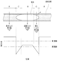
- the upper part is a graph showing the state of bubbles in the transparent tube
- the lower part is a graph showing the relationship between the bubble position and the output (light receiving amount) of the light receiving element.
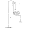
- It is explanatory drawing which shows the separation action of a liquid detergent and air in a transparent tube. It is explanatory drawing which shows the structure which secures the predetermined amount of liquid detergent in a transparent tube.
- FIG. 1 is a front view showing the configuration of a washing system including a washing machine 100, which is an application example of the present invention.
- This washing system consists of a washing machine 100, a liquid detergent container 200 and a transparent tube 20.
- the washing machine 100 can be used as a commercial washing machine by mounting the attachment device 120 on the upper surface of the washing machine main body 110. Further, the washing machine 100 receives the liquid detergent from the liquid detergent container 200 via the transparent tube 20.
- FIG. 1 illustrates a configuration in which one washing machine 100 is connected to one liquid detergent container 200, a plurality of washing machines 100 are connected to one liquid detergent container 200. You may be.
- FIG. 2 is a perspective view of the inside of the attachment device 120 as viewed from the rear side.
- the illustration of the outer housing is partially omitted.
- a liquid detergent detection device 10 attached together with the transparent tube 20 is arranged inside the attachment device 120.
- the attached device 120 also includes a pump 30 for sending the liquid detergent from the liquid detergent container 200 to the washing machine 100 via the transparent tube 20, and a charging device 40 for the user using the washing machine 100 to pay a fee. It is equipped.
- the liquid detergent detection device 10 has a tube mounting groove 11 for mounting the transparent tube 20 and a photo interrupter 12.
- the photo interrupter 12 is an example of a light emitting element and a light receiving element described in the claims.
- the liquid detergent detection device 10 has a control unit (not shown) for determining the presence or absence of liquid detergent in the transparent tube 20 based on the output of the photo interrupter 12.
- the transparent tube 20 is attached to the liquid detergent detection device 10 by being fitted into the tube attachment groove 11.
- the transparent tube 20 is attached to the liquid detergent detection device 10 so as to extend in the vertical direction.
- the photo interrupter 12 is arranged so that the transparent tube 20 in the middle of the tube mounting groove 11 can be detected.
- the photo interrupter 12 has a light emitting element 12a (see FIG. 3) and a light receiving element 12b (see FIG. 3) arranged so as to sandwich the transparent tube 20 so as to be opposed to each other.
- the photo interrupter 12 has tube holding portions 12c at both ends of the transparent tube 20 in the extending direction (vertical direction in FIG. 1).
- the light emitting element 12a and the light receiving element 12b are not limited to the configurations provided in the photo interrupter 12.
- the liquid detergent detection device 10 may hold the light emitting element 12a and the light receiving element 12b, respectively.
- the detection principle of the case where the liquid detergent is present in the transparent tube 20 and the case where the liquid detergent is not present will be described with reference to FIGS. 3 (a) and 3 (b).
- FIG. 3A shows the detection principle when there is a liquid detergent in the transparent tube 20.
- the light emitting element 12a irradiates the transparent tube 20 with diffused light.
- the light transmitted through the transparent tube 20 is refracted by the liquid detergent in the transparent tube 20 and focused toward the light receiving element 12b.
- the light receiving element 12b can receive most of the light transmitted through the transparent tube 20.
- all (or almost all) of the diffused light emitted from the light emitting element 12a toward the transparent tube 20 is applied to the transparent tube 20.
- the transparent tube 20 has a shape having a convex curved surface such as a circle or an ellipse in its cross section in order to obtain a light collecting action.
- FIG. 3B shows the detection principle when there is no liquid detergent in the transparent tube 20.
- the light transmitted through the transparent tube 20 continues to diffuse without being focused, and the light receiving element 12b can receive only a part of the light transmitted through the transparent tube 20.
- the amount of light received by the light receiving element 12b differs depending on whether or not there is a light collecting action in the transparent tube 20 with or without the liquid detergent.
- the control unit included in the liquid detergent detection device 10 compares the output of the light receiving element 12b with a predetermined first threshold value, and when the output of the light receiving element 12b is larger than the first threshold value, the liquid detergent is contained in the transparent tube 20. If the output of the light receiving element 12b is smaller than the first threshold value, it can be determined that there is no liquid detergent in the transparent tube 20.
- the transparent tube 20 needs to be arranged at an appropriate position with respect to the light emitting element 12a and the light receiving element 12b.
- such an appropriate arrangement can be obtained by providing the photo interrupter 12 with the tube holding portion 12c and holding and fixing the transparent tube 20 by the tube holding portion 12c.
- the amount of light received by the light receiving element 12b when there is no liquid detergent in the transparent tube 20 differs depending on the area of the light receiving portion of the light receiving element 12b.
- the smaller the area of the light receiving portion of the light receiving element 12b the smaller the amount of light received by the light receiving element 12b when there is no liquid detergent, and the light receiving element with and without the liquid detergent in the transparent tube 20.
- the output difference of 12b can be made large. Therefore, the area of the light receiving portion of the light receiving element 12b may be set according to the level of the light receiving amount of the light receiving element 12b when there is no liquid detergent in the transparent tube 20.
- the shape of the light receiving portion of the light receiving element 12b is preferably a slit shape in which the direction in which the transparent tube 20 extends (vertical direction in FIG. 2) is the longitudinal direction. Since the transparent tube 20 has a cylindrical shape, almost no light collecting action can be obtained in the direction in which the transparent tube 20 extends, but the light collecting action shown in FIG. 3 can be obtained in the direction along the cross section of the transparent tube 20. Therefore, by making the shape of the light receiving portion of the light receiving element 12b a narrow slit shape in the vertical direction in FIG. 3, the output difference of the light receiving element 12b with and without the liquid detergent in the transparent tube 20 can be made large.
- the longitudinal direction of the slit By setting the longitudinal direction of the slit to the direction in which the transparent tube 20 extends (the front-back direction of the paper surface in FIG. 3), more irradiation light from the light emitting element 12a can be received, so that the signal intensity of the light receiving element 12b can be increased. Can be improved.
- the transparent tube 20 is premised on sending liquid from the liquid detergent container 200 to the washing machine 100, but when the remaining amount of the liquid detergent in the liquid detergent container 200 becomes low, the transparent tube 20 is used. Bubbles will be mixed in the liquid detergent in 20. Such bubbles form a curved interface so as to separate the air and the liquid detergent in the axial direction of the transparent tube 20.
- the liquid detergent detection device 10 compares the output (light receiving amount) of the light receiving element 12b with the second threshold value ( ⁇ first threshold value) to compare the interface (bubble end) of bubbles in the transparent tube 20. It is also possible to detect a part area).
- the detection principle will be described with reference to FIG.
- the upper part of FIG. 4 is a diagram showing the state of bubbles in the transparent tube 20, and the lower part of FIG. 4 is a graph showing the relationship between the position of bubbles and the output (light receiving amount) of the light receiving element 12b.
- the region where the liquid detergent is present (there is no air bubble) in the transparent tube 20 is defined as the region A, and there is no liquid detergent in the transparent tube 20 (the air is present and the interface between the air and the liquid detergent does not exist).
- Region B, and region C where the bubble end is present (the interface between air and the liquid detergent is present) in the transparent tube 20 are defined as the region A, and there is no liquid detergent in the transparent tube 20 (the air is present and the interface between the air and the liquid detergent does not exist).
- the amount of light received becomes “large” by condensing the light transmitted through the transparent tube 20.
- the amount of light received becomes “medium” due to the diffusion of the light transmitted through the transparent tube 20. Therefore, by setting the above-mentioned first threshold value between the light receiving amount in the region A and the light receiving amount in the region B, when the output of the light receiving element 12b is larger than the first threshold value, the liquid is contained in the transparent tube 20. It can be determined that there is detergent.
- the irradiation light from the light emitting element 12a hits the end of the bubble, that is, the interface between the air and the liquid detergent, and is reflected and scattered. Therefore, the light transmitted straight through the transparent tube 20 (FIG. The amount of light (light in the direction of the arrow from top to bottom) in region C of 4 is reduced. As a result, in the region C, the amount of light received becomes "small". Therefore, by setting a second threshold value between the light receiving amount in the region B and the light receiving amount in the region C, the bubble end portion in the transparent tube 20 when the output of the light receiving element 12b is smaller than the second threshold value. Can be detected. Then, when the output of the light receiving element 12b is smaller than the first threshold value and larger than the second threshold value, it can be determined that there is no liquid detergent in the transparent tube 20.
- the liquid detergent detection device 10 changes the output of the light receiving element 12b by utilizing the presence or absence of the condensing action depending on whether the transparent tube 20 has the liquid detergent or not. Is what causes. Therefore, when the liquid detergent flowing through the transparent tube has high transparency, the output difference of the light receiving element 12b can be made large, and the presence or absence of the highly transparent liquid detergent can be determined regardless of the usage conditions of the liquid detergent detection device 10. It can be detected with high accuracy.
- the air bubbles can be detected by using the scattering of light at the end of the air bubbles.
- the air bubbles can be detected that the remaining amount of the liquid detergent container 200 is low.
- the liquid detergent sent by the transparent tube 20 it is possible to detect the mixing rate of air bubbles and, based on this, more accurately control the amount of the liquid detergent supplied to the washing machine 100.
- the transparent tube 20 has a substantially inverted U-shaped arrangement portion in the attachment device 120.
- the substantially inverted U-shaped arrangement portion of the transparent tube 20 includes the first standing portion 21 and the second standing portion 22 extending in the vertical direction, and the first standing portion 21 and the second standing portion 22 at the upper part. It is formed by a bent portion 23 to be connected.
- the second erection part 22 is on the downstream side in the flow direction of the liquid detergent. Therefore, when the pump 30 is operated to send the liquid from the liquid detergent container 200 to the washing machine 100, the liquid detergent lowers the first standing portion 21 at the substantially inverted U-shaped arrangement portion of the transparent tube 20.
- the liquid detergent detection device 10 is attached at a position on the downstream side in the flow direction of the liquid detergent from the bent portion 23.
- the liquid detergent detection device 10 is attached to the second standing portion 22.
- the washing machine 100 When the washing machine 100 is used, an appropriate amount of liquid detergent needs to be supplied from the liquid detergent container 200 to the washing machine 100, and the supply amount of the liquid detergent is controlled by the driving time of the pump 30.
- the driving time of the pump 30 is lengthened as compared with the case where the liquid detergent flowing through the transparent tube 20 does not contain air bubbles, so that an appropriate amount of liquid detergent is controlled to be supplied.
- the drive time of the pump 30 is doubled to increase the supply amount of the liquid detergent. It can be the same as when there is no air bubbles mixed in.
- the liquid detergent detection device 10 when the liquid detergent flowing through the transparent tube 20 is mixed with the liquid detergent, the liquid detergent detection device 10 includes a region A in which the air bubbles do not exist and a region B in which the central portion of the air bubbles exists. , It is possible to distinguish and detect the region C where the bubble end portion exists. Based on this, the mixing rate of air bubbles in the transparent tube 20 can also be detected.
- the transparent tube 20 has a substantially inverted U-shaped arrangement portion (first standing portion 21, bent portion 23, and second standing portion 22).
- the liquid detergent detection device 10 is attached to a second standing portion 22 through which the liquid detergent flows from top to bottom.
- the liquid detergent spreads along the inner wall of the transparent tube 20.
- the mixing rate of air bubbles in the transparent tube 20 is high and the amount of liquid detergent between adjacent air bubbles is small, as shown in FIG. 5, the liquid detergent between air bubbles spreads along the inner wall of the tube, so that the liquid detergent The vertical width of is reduced.
- the width of the liquid detergent cannot maintain the interface with the bubbles, the liquid detergent forming the interface with the bubbles falls down along the inner wall of the tube. That is, in the first standing portion 21, a so-called bubble breaking effect that eliminates a small interface between bubbles occurs.
- the washing machine 100 has a bent portion 23 on the upper portion of the first standing portion 21, that is, on the downstream side in the flow direction of the liquid detergent.
- the width of the liquid detergent in the vertical direction decreases as described above.
- the width direction of the liquid detergent changes from the vertical direction to the horizontal direction.
- the width of the liquid detergent in the bent portion 23 becomes non-uniform in the left-right direction due to gravity.
- the liquid detergent is concentrated downward, and the liquid detergent above is insufficient.
- the liquid detergent cannot maintain the interface with the bubbles above the inside of the transparent tube 20 of the bent portion 23, and the interface with the bubbles disappears. Therefore, the so-called bubble breaking effect, which eliminates the small-scale interface between bubbles, can be enhanced by the inside of the bent portion 23.
- the liquid detergent mixed with air bubbles is separated into the liquid detergent and air by the first standing portion 21 and the bent portion 23, and only large air bubbles are sent to the liquid detergent detection device 10.
- the liquid detergent detecting device 10 can prevent the liquid detergent mixed with many small bubbles from continuing to flow for a long period of time, and can appropriately detect the liquid detergent running out in the liquid detergent container 200.
- the liquid detergent detection device 10 detects the above-mentioned regions A to C, respectively, and calculates the cumulative amount of liquid detergent and air from the ratio of each of these regions. , Calculate the mixing rate of air bubbles.
- the detection error increases as the number of small air bubbles is included. This is because, in a state where many small bubbles are contained, the cumulative calculation of the regions A to C increases, and the cumulative error also increases. Further, in a state where many small bubbles are contained, the ratio of the region C in which both the liquid detergent and the air are present increases, which also leads to an increase in error.
- the transparent tube 20 is provided with a substantially inverted U-shaped arrangement portion (particularly, the first standing portion 21 and the bent portion 23), the process of flowing the first standing portion 21 from the bottom to the top and bending.
- the liquid detergent between the bubbles cannot maintain the interface with the bubbles, and a phenomenon occurs in which the small bubbles are combined to form a large bubble. That is, even if the first standing portion 21 contains many small bubbles, the second standing portion 22 provided with the liquid detergent detection device 10 has few small bubbles and an increased number of large bubbles. .. As a result, the accuracy of detecting the mixing rate of air bubbles in the transparent tube 20 can be improved.
- the interface with the air bubbles is largely removed on the downstream side by the first standing portion 21 and the bent portion 23. Therefore, when the pump 30 is stopped, the probability that an interface with air bubbles exists in the transparent tube 20 at the detection location of the liquid detergent detection device 10 can be significantly reduced. If the liquid detergent that is the interface with the air bubbles remains, it sticks to the inside of the transparent tube 20 and tends to become dirty. However, with the above configuration, it is possible to prevent the inside of the transparent tube 20 from becoming dirty at the detection location of the liquid detergent detection device 10. , The detection accuracy of the liquid detergent detection device 10 can be maintained.
- the liquid detergent container 200 can be detected as running out of detergent by detecting the liquid detergent in the transparent tube 20 by the liquid detergent detecting device 10. Then, when the liquid detergent detection device 10 detects that the detergent has run out, the administrator of the washing machine 100 or the like replenishes the liquid detergent container 200 with the liquid detergent.
- the liquid detergent container 200 is simply refilled with the liquid detergent, the liquid detergent is not filled between the end of the transparent tube 20 on the liquid detergent container 200 side and the liquid detergent detection device 10 at that time. It has become. Therefore, when the washing machine 100 is used from such a state, even if the pump 30 is operated to supply the liquid detergent, the liquid detergent does not reach the liquid detergent detection device 10 for a while, and the liquid detergent detection device 10 does not reach the liquid detergent detection device 10. It is possible that the detergent will run out again.
- the detergent runs out.
- an error clearing operation such as a predetermined button operation
- the operation is performed after the error is cleared.
- the operation after the error is released includes at least the initial filling operation of the transparent tube 20.
- Such an initial filling operation is performed by operating the pump 30 until the transparent tube 20 is filled with the liquid detergent.
- the pump 30 is operated to start filling the transparent tube 20 with the liquid detergent, and after the liquid detergent detection device 10 detects the presence of the liquid detergent, the pump 30 is further operated for a predetermined time.
- the liquid detergent can be filled up to the tip of the transparent tube 20 (the end on the washing machine body 110 side).
- the liquid detergent detection device 10 may not perform the detection operation for a predetermined time after the pump 30 starts operating, and may start the detection operation after the lapse of a predetermined time. This is because even if the pump 30 is operated without the liquid detergent in the transparent tube 20, the liquid detergent does not reach the liquid detergent detection device 10 for a while, and it is considered that the detection operation does not need to be performed. .. Therefore, during the period when the liquid detergent is not expected to reach the liquid detergent detection device 10, the detection operation of the liquid detergent detection device 10 can be stopped to suppress unnecessary operation of the liquid detergent detection device 10.
- a predetermined time-out period is provided from the start of operation of the pump 30 to the detection of the liquid detergent in the liquid detergent detection device 10, and if the liquid detergent is not detected within the time-out period, the initial filling operation is terminated. Then, it is preferable to detect the detergent shortage again.
- the manager of the washing machine 100 performs a detergent exhaustion error clearing operation without replenishing the liquid detergent container 200 with the liquid detergent, and the pump 30 does not fill the transparent tube 20 with the detergent. It is possible to avoid that only keeps working.
- the liquid detergent detecting device 10 detects the presence of the liquid detergent, the liquid detergent is completely filled up to the tip of the transparent tube 20 (the end on the washing machine body 110 side). Further, the pump 30 is operated for a predetermined time. In this case, it is conceivable that some liquid detergent is contained in the washing tub of the washing machine main body 110 at the end of the initial filling operation. Therefore, it is preferable that the operation after the error is released includes the washing tub washing operation of the washing machine main body 110, and the washing tub washing operation is performed after the initial filling operation.
- the washing machine 100 for example, as shown in FIG. 6, when the transparent tube 20 has a length on the downstream side of the liquid detergent detection device 10 and the liquid detergent detection device 10 detects that the liquid detergent has run out. Therefore, it is preferable that a predetermined amount (preferably about one washing) of liquid detergent is secured in the transparent tube 20 downstream of the liquid detergent detection device 10. In this configuration, even if the user detects that the washing machine 100 has run out of liquid detergent, the amount of liquid detergent required for one washing is secured in the transparent tube 20, and the user pays a fee. However, it is possible to avoid the situation where the liquid detergent is insufficient.
- the method of securing a predetermined amount of liquid detergent in the transparent tube 20 is not particularly limited, and in addition to the method of giving the transparent tube 20 a length, for example, a reserve tank is provided in the middle of the transparent tube 20.
- the method etc. can be considered.
- the type of the pump 30 used for sending the liquid detergent is not particularly limited, but different effects occur depending on the type of the pump 30 used. To do. For example, when the pump 30 is of a type that does not generate pulsation, the speed change becomes small in the liquid detergent flowing through the transparent tube 20. In this case, in a state where the liquid detergent flowing through the transparent tube 20 is mixed with air bubbles, the detection accuracy of the mixing rate of the air bubbles in the transparent tube 20 becomes high. On the other hand, when the pump 30 is of a type that generates pulsation, the speed change becomes large in the liquid detergent flowing through the transparent tube 20. In this case, bubbles are likely to be crushed in the process of intermittent acceleration / deceleration in the flow of the liquid detergent in the transparent tube 20, and the effect of breaking bubbles in the first standing portion 21 of the transparent tube 20 is enhanced.
Landscapes
- Physics & Mathematics (AREA)
- Fluid Mechanics (AREA)
- General Physics & Mathematics (AREA)
- Engineering & Computer Science (AREA)
- Textile Engineering (AREA)
- Control Of Washing Machine And Dryer (AREA)
- Detail Structures Of Washing Machines And Dryers (AREA)
- Measurement Of Levels Of Liquids Or Fluent Solid Materials (AREA)
Abstract
液体洗剤検知装置は、発光素子および受光素子を有する。透明チューブ内に液体洗剤がある場合、透明チューブに照射された拡散光が屈折を受けて集光され、受光素子は集光された光を受光する。透明チューブ内に液体洗剤がない場合、透明チューブに照射された拡散光が透明チューブ内の透過後も拡散を続け、受光素子は透明チューブを透過した光の一部を受光する。液体洗剤検知装置の制御部は、受光素子の出力が第1閾値よりも高い場合に透明チューブ内に液体洗剤があることを検知し、受光素子の出力が第1閾値よりも低い場合に透明チューブ内に液体洗剤がないことを検知する。
Description
本発明は、液体洗剤容器からチューブを用いた送液によって液体洗剤の供給を受ける構成の洗濯機において、チューブを流れる液体洗剤の有無を検知する液体洗剤検知装置、およびそれを用いた洗濯機に関する。本願は、2019年3月15日に、日本に出願された特願2019-48363に優先権を主張し、その内容をここに援用する。
近年の洗濯機は洗剤の自動投入機能を備えているものが多くある。例えば、業務用の洗濯機などでは、大型の液体洗剤容器と洗濯機とをチューブで繋ぎ、液体洗剤容器からチューブを用いて送液し、液体洗剤の供給が行われている。
このようなチューブを用いた送液では、液体洗剤容器における液体洗剤の有無を検知したり、正確な送液量の制御を行ったりするためにチューブ内の液体洗剤検知が不可欠である。特許文献1には、フォトインタラプタを用いた液体洗剤やシャンプーなどの流体検知装置が開示されている。特許文献1に開示された流体検知装置における検知方法は、フォトインタラプタの発光素子から照射される光を透明チューブに透過させ、その透過光量を受光素子で検知することで透明チューブ内の流体(液体洗剤やシャンプー)の有無を検知するというものである。具体的には、透明チューブ内に流体が存在するときには該流体によって光が遮られて透過光量が減少するため、受光素子の出力を閾値と比較することで透明チューブ内の流体の有無を検知できる。
特許文献1に記載の流体検知装置では、透明チューブを流れる流体の透明度が低いことが高精度な検知を行うための条件となる。しかしながら、この流体検知装置を洗濯機に適用する場合、液体洗剤には透明度の高いものが多くあり、高精度の検知が難しいといった問題がある。これは、透明度の高い液体洗剤では、透明チューブ内における洗剤の有無による透過光量の差が小さくなるためである。また、フォトインタラプタなどの光センサデバイスは、温度変化や経年劣化によって出力レベルが変化しやすく、洗剤の有無による透過光量の差が小さければ、使用条件によっては誤検知を招く虞がある。
本発明の一態様は、上記課題に鑑みてなされたものであり、透明チューブを流れる透明度の高い液体洗剤の有無を高精度に検知することのできる液体洗剤検知装置およびそれを用いた洗濯機を提供することを目的とする。
上記の課題を解決するために、本発明の第1の態様である液体洗剤検知装置は、透明チューブを取り付けて使用するものであり、前記透明チューブ内の液体洗剤の有無を検知する液体洗剤検知装置であって、前記透明チューブを挟んで対向配置される発光素子および受光素子と、前記透明チューブを前記液体洗剤検知装置に対して適切な位置に保持するチューブ保持部と前記受光素子の受光量に基づいて透明チューブ内の液体洗剤の有無を検知する制御部とを備えており、前記発光素子は前記透明チューブに拡散光を照射するものであり、前記発光素子および前記受光素子は、(1)前記透明チューブ内に液体洗剤がある場合、前記透明チューブに照射された前記拡散光が前記透明チューブ内の液体洗剤によって屈折を受けて集光され、前記受光素子は集光された光を受光し、(2)前記透明チューブ内に液体洗剤がない場合、前記透明チューブに照射された前記拡散光が前記透明チューブ内の透過後も拡散を続け、前記受光素子は前記透明チューブを透過した光の一部を受光する構成とされており、前記制御部は、前記受光素子の出力が第1閾値よりも高い場合に前記透明チューブ内に液体洗剤があることを検知し、前記受光素子の出力が第1閾値よりも低い場合に前記透明チューブ内に液体洗剤がないことを検知することを特徴としている。
上記の構成によれば、液体洗剤検知装置は、透明チューブ内に液体洗剤がある場合とない場合との集光作用の有無を利用して、受光素子の出力に変化を生じさせることができる。そのため、透明チューブを流れる液体洗剤が透明度の高いものである場合に受光素子の出力差を大きく取ることができ、液体洗剤検知装置の使用条件に関わらず、透明度の高い液体洗剤の有無を高精度に検知することができる。
また、上記液体洗剤検知装置は、前記透明チューブ内を流れる液体洗剤に気泡が混じる場合に、前記第1閾値よりも値が小さい第2閾値を用いて気泡の端部を検知可能であり、前記制御部は、前記受光素子の出力が第2閾値よりも低い場合に気泡の端部を検知する構成とすることができる。
上記の構成によれば、透明チューブ内に気泡が存在する場合に、気泡の端部検知に基づいて気泡を高精度に検知することができる。透明チューブに繋がれる液体洗剤容器の残量が少なくなると透明チューブ内に気泡が発生するため、これにより液体洗剤容器の残量が少ないことを検知することができる。
また、上記液体洗剤検知装置では、前記制御部は、前記透明チューブを流れる液体洗剤に気泡が混じる場合に、気泡が存在しない領域と、気泡が存在する領域と、気泡端部が存在する領域とを区別して検知し、これらの各領域の割合から気泡の混入率を算出可能である構成とすることができる。
上記の構成によれば、透明チューブで送液される液体洗剤において、気泡の混入率を算出し、算出した気泡の混入率を洗濯機への液体洗剤の供給量制御に利用することができる。
また、上記の課題を解決するために、本発明の第2の態様である洗濯機は、外部の液体洗剤容器から透明チューブを介して液体洗剤の供給を受ける洗濯機であって、前記透明チューブに取り付けられた前記記載の液体洗剤検知装置を含むことを特徴としている。
また、上記洗濯機では、前記透明チューブは、上下方向に延びる第1立設部および第2立設部と、前記第1立設部および前記第2立設部を上部で繋ぐ屈曲部とで形成された略逆U字状の配設部分を有しており、前記液体洗剤検知装置は、前記屈曲部よりも液体洗剤の流れ方向下流側に取り付けられている構成とすることができる。
上記の構成によれば、液体洗剤が第1立設部を下から上へ流れる過程や屈曲部を流れる過程で、気泡の混じった液体洗剤を液体洗剤と空気とに分離する泡切れ効果が発生する。その結果、屈曲部よりも下流側に液体洗剤検知装置を取り付けることで、小さな気泡が混じった液体洗剤が液体洗剤検知装置の設置位置に流れることが抑制され、液体洗剤検知装置が液体洗剤切れを適正に検知することができる。あるいは、透明チューブ内の気泡の混入率の検出精度を向上させることができる。
また、上記洗濯機は、前記液体洗剤検知装置によって前記透明チューブ内の液体洗剤切れが検知された後、ユーザによる洗剤切れエラー解除操作に応じてエラー解除後動作を行うものであり、前記エラー解除後動作は、前記透明チューブ内に液体洗剤を充填する初期充填動作を含む構成とすることができる。
上記の構成によれば、透明チューブ内の液体洗剤切れが検知された後、液体洗剤容器に液体洗剤の補充を行ってから初期充填動作を行わせることで、透明チューブに液体洗剤を充填することができる。これにより、洗濯機の次回使用時に、液体洗剤検知装置まで液体洗剤が届く前に、液体洗剤検知装置が再び液体洗剤切れを検知してしまうことを防止できる。
また、上記洗濯機は、前記初期充填動作の開始後、所定のタイムアウト期間内に前記液体洗剤検知装置によって前記透明チューブ内の液体洗剤ありが検知されない場合、前記初期充填動作を終了し、前記透明チューブ内の液体洗剤切れを再度検知する構成とすることができる。
上記の構成によれば、洗濯機の管理者などが液体洗剤容器に対して液体洗剤の補充を行わずに洗剤切れエラー解除操作を行った場合、透明チューブに対して洗剤充填がなされないまま、ポンプのみが作動し続けるといったことを回避できる。
また、上記洗濯機では、前記初期充填動作は、前記液体洗剤検知装置によって前記透明チューブ内の液体洗剤ありが検知された後、前記透明チューブに接続されたポンプを所定時間作動させてから終了するものであり、前記エラー解除後動作は、前記初期充填動作の後に行う洗濯槽洗浄動作を含む構成とすることができる。
上記の構成によれば、液体洗剤検知装置によって透明チューブ内の液体洗剤ありが検知された後もポンプを所定時間作動させることで、透明チューブの先端にまで液体洗剤を完全に充填させることができる。また、この場合、初期充填動作の終了時点において、洗濯機の洗濯槽にいくらかの液体洗剤が入っていることが考えられるため、初期充填動作の後に洗濯槽洗浄動作を行う。
本発明の一態様である液体洗剤検知装置および洗濯機は、透明チューブ内に液体洗剤がある場合とない場合との集光作用の有無を利用して、受光素子の出力に変化を生じさせる。これにより、透明チューブを流れる液体洗剤が透明度の高いものである場合に受光素子の出力差を大きく取ることができ、液体洗剤検知装置の使用条件に関わらず、透明度の高い液体洗剤の有無を高精度に検知することができるといった効果を奏する。
〔実施の形態1〕
以下、本発明の実施の形態について、図面を参照して詳細に説明する。本実施の形態1では、透明チューブを流れる透明度の高い液体洗剤の有無を高精度に検知することのできる液体洗剤検知装置について説明する。
以下、本発明の実施の形態について、図面を参照して詳細に説明する。本実施の形態1では、透明チューブを流れる透明度の高い液体洗剤の有無を高精度に検知することのできる液体洗剤検知装置について説明する。
図1は、本発明の一適用例である洗濯機100を含む洗濯システムの構成を示す正面図である。この洗濯システムは、洗濯機100、液体洗剤容器200および透明チューブ20により構成されている。洗濯機100は、洗濯機本体110の上面に付設装置120を搭載することにより業務用洗濯機として使用可能とされている。また、洗濯機100は、液体洗剤容器200から透明チューブ20を介して液体洗剤の供給を受けるようになっている。尚、図1では、1つの液体洗剤容器200に対して1台の洗濯機100が繋がれた構成を例示しているが、1つの液体洗剤容器200に対して複数の洗濯機100が繋がれていてもよい。
図2は、付設装置120の内部を背面側から見た斜視図である。尚、図2では、付設装置120の内部を図示するために、外部筐体の図示を一部省略している。付設装置120の内部には、透明チューブ20と共に取り付けられた液体洗剤検知装置10が配置されている。また、付設装置120には、液体洗剤容器200から洗濯機100へ透明チューブ20を介して液体洗剤を送り込むためのポンプ30や、洗濯機100を使用するユーザが料金を支払うための課金装置40も備えられている。
図2に示すように、液体洗剤検知装置10は、透明チューブ20を取り付けるためのチューブ取付溝11と、フォトインタラプタ12とを有している。フォトインタラプタ12は、特許請求の範囲に記載の発光素子および受光素子の一例である。また、液体洗剤検知装置10は、フォトインタラプタ12の出力に基づいて透明チューブ20内の液体洗剤の有無を判定する制御部(図示せず)を有している。
透明チューブ20は、チューブ取付溝11に嵌入されることによって、液体洗剤検知装置10に対して取り付けられる。本実施の形態では、液体洗剤検知装置10に対して透明チューブ20が上下方向に延びるように取り付けられている。フォトインタラプタ12は、チューブ取付溝11の途中の透明チューブ20に対して検知を行えるように配置されている。フォトインタラプタ12は、その内部に、透明チューブ20を挟むようにして対向配置される発光素子12a(図3参照)および受光素子12b(図3参照)を有している。さらに、フォトインタラプタ12は、透明チューブ20の延設方向(図1では上下方向)の両端に、チューブ保持部12cを有している。尚、発光素子12aおよび受光素子12bについては、フォトインタラプタ12内に有する構成に限らない。例えば、液体洗剤検知装置10が発光素子12aおよび受光素子12bをそれぞれ保持する形態としてもよい。
続いて、液体洗剤検知装置10において、透明チューブ20内に液体洗剤がある場合とない場合との検知原理を図3(a),(b)を参照して説明する。
図3(a)は、透明チューブ20内に液体洗剤がある場合の検知原理を示すものである。まず、発光素子12aは、透明チューブ20に対して拡散光を照射する。液体洗剤がある場合、透明チューブ20を透過する光は、透明チューブ20内の液体洗剤によって屈折を受け、受光素子12bに向けて集光される。その結果、受光素子12bは、透明チューブ20を透過した光の多くを受光することができる。尚、発光素子12aから透明チューブ20に向けて照射される拡散光は、その全て(もしくはほぼ全て)が透明チューブ20に照射されることが好ましい。また、透明チューブ20は、集光作用を得るために、その断面が円や楕円などの凸曲面を有する形状とされている。
図3(b)は、透明チューブ20内に液体洗剤がない場合の検知原理を示すものである。液体洗剤がない場合、透明チューブ20を透過する光は集光されずに拡散を続け、受光素子12bは、透明チューブ20を透過した光の一部しか受光することができない。
このように、本実施の形態1に係る液体洗剤検知装置10は、透明チューブ20内に液体洗剤がある場合とない場合との集光作用の有無によって、受光素子12bにおける受光量を異ならせている。その結果、液体洗剤検知装置10が備える制御部は、受光素子12bの出力を所定の第1閾値と比較し、受光素子12bの出力が第1閾値よりも大きい場合は透明チューブ20内に液体洗剤があると判定し、受光素子12bの出力が第1閾値よりも小さい場合は透明チューブ20内に液体洗剤がないと判定することができる。
尚、液体洗剤検知装置10の上記検知原理においては、透明チューブ20内に液体洗剤がある場合に、透明チューブ20を透過する光を受光素子12bの受光面において十分に集光させる必要がある。このため、フォトインタラプタ12において、透明チューブ20は発光素子12aおよび受光素子12bに対して適切な位置に配置されている必要がある。液体洗剤検知装置10では、フォトインタラプタ12にチューブ保持部12cを設け、チューブ保持部12cによって透明チューブ20を保持・固定することにより、そのような適切な配置が得られるようになっている。
また、液体洗剤検知装置10では、発光素子12aおよび受光素子12bの配置位置だけでなく、受光素子12bの受光部面積も重要な要素となる。すなわち、透明チューブ20内に液体洗剤がない場合の受光素子12bの受光量は、受光素子12bの受光部面積により異なる。具体的には、受光素子12bの受光部面積を小さくするほど、液体洗剤がない場合の受光素子12bの受光量も小さくなり、透明チューブ20内に液体洗剤がある場合とない場合との受光素子12bの出力差を大きく取ることができる。このため、受光素子12bの受光部面積は、透明チューブ20内に液体洗剤がない場合の受光素子12bの受光量をどの程度のレベルとするかに応じて設定すればよい。
また、受光素子12bの受光部形状は、透明チューブ20が延びる方向(図2では上下方向)が長手方向となるスリット形状とすることが好ましい。透明チューブ20は円筒形状であるため、透明チューブ20が延びる方向では集光作用がほとんど得られないが、透明チューブ20の断面に沿う方向では、図3に示す集光作用が得られる。したがって、受光素子12bの受光部形状を、図3における上下方向で狭いスリット形状とすることで、透明チューブ20内に液体洗剤がある場合とない場合との受光素子12bの出力差を大きく取ることができ、また、スリットの長手方向を透明チューブ20が延びる方向(図3における紙面前後方向)とすることで、発光素子12aからの照射光をより多く受光できるので、受光素子12bの信号強度を向上できる。
また、本実施の形態1において、透明チューブ20は液体洗剤容器200から洗濯機100への送液を行うことを前提としているが、液体洗剤容器200における液体洗剤の残量が少なくなると、透明チューブ20内の液体洗剤には気泡が混じるようになる。このような気泡は、透明チューブ20の軸方向において、空気と液体洗剤とを分断するように曲面状の界面を形成する。
本実施の形態1に係る液体洗剤検知装置10は、受光素子12bの出力(受光量)を第2閾値(<第1閾値)と比較することで、透明チューブ20内における気泡の界面(気泡端部領域)をも検知可能である。その検知原理を、図4を参照して説明する。図4の上部は透明チューブ20内における気泡の状態を示す図であり、図4の下部は気泡位置と受光素子12bの出力(受光量)との関係を示すグラフである。図4では、透明チューブ20内に液体洗剤がある(気泡が存在しない)領域を領域Aとし、透明チューブ20内に液体洗剤がない(気泡が存在し、空気と液体洗剤との界面は存在しない)領域を領域Bとし、透明チューブ20内に気泡端部が存在する(空気と液体洗剤との界面が存在する)領域を領域Cとしている。
まず、領域Aでは、図3(a)に示したように、透明チューブ20を透過する光が集光されることによって受光量は“大”となる。また、領域Bでは、図3(b)に示したように、透明チューブ20を透過する光が拡散することによって受光量は“中”となる。このため、領域Aの受光量と領域Bの受光量との間に上述した第1閾値とを設定することで、受光素子12bの出力が第1閾値よりも大きい場合に透明チューブ20内に液体洗剤があると判定することができる。
一方、領域Cでは、発光素子12aからの照射光は、気泡の端部、すなわち空気と液体洗剤との界面に当たって反射され、散乱してしまうため、透明チューブ20を直進して透過する光(図4の領域Cにおける上から下への矢印方向の光)の光量が減少する。その結果、領域Cでは、受光量は“小”となる。このため、領域Bの受光量と領域Cの受光量との間に第2閾値とを設定することで、受光素子12bの出力が第2閾値よりも小さい場合に透明チューブ20内における気泡端部を検知することができる。そして、受光素子12bの出力が、第1閾値よりも小さく第2閾値よりも大きい場合には、透明チューブ20内に液体洗剤がないと判定することができる。
このように、本実施の形態1に係る液体洗剤検知装置10は、透明チューブ20内に液体洗剤がある場合とない場合との集光作用の有無を利用して、受光素子12bの出力に変化を生じさせるものである。そのため、透明チューブを流れる液体洗剤が透明度の高いものである場合に受光素子12bの出力差を大きく取ることができ、液体洗剤検知装置10の使用条件に関わらず、透明度の高い液体洗剤の有無を高精度に検知することができる。
また、透明チューブ20内に気泡が存在する場合には、気泡端部での光の散乱を利用して、気泡を検知することもできる。これにより、透明チューブ20で送液される液体洗剤に気泡が混入した場合に、液体洗剤容器200の残量が少ないと検知することもできる。また、透明チューブ20で送液される液体洗剤において、気泡の混入率を検出し、これに基づいて、洗濯機100への液体洗剤の供給量をより正確に制御することも可能となる。
〔実施の形態2〕
本実施の形態2では、洗濯機100における液体洗剤検知装置10の好適な使用形態について説明する。
本実施の形態2では、洗濯機100における液体洗剤検知装置10の好適な使用形態について説明する。
図2に示すように、付設装置120内において、透明チューブ20は略逆U字状の配設部分を有している。透明チューブ20の略逆U字状の配設部分は、上下方向に延びる第1立設部21および第2立設部22と、第1立設部21および第2立設部22を上部で繋ぐ屈曲部23とで形成されている。第1立設部21および第2立設部22は、第2立設部22が液体洗剤の流れ方向の下流側とされている。したがって、ポンプ30を作動させて液体洗剤容器200から洗濯機100への送液を行う場合、透明チューブ20の略逆U字状の配設部分では、液体洗剤は第1立設部21を下から上に向かって流れた後、屈曲部23で流れの向きを変えられ、第2立設部22を上から下に向かって流れる。そして、液体洗剤検知装置10は、屈曲部23よりも液体洗剤の流れ方向の下流側となる位置に取り付けられる。本実施の形態では、液体洗剤検知装置10は、第2立設部22に取り付けられる。
洗濯機100の使用時、液体洗剤容器200から洗濯機100へは、適量の液体洗剤が供給される必要があり、液体洗剤の供給量はポンプ30の駆動時間によって制御される。但し、液体洗剤容器200における液体洗剤の残量が少なくなり、透明チューブ20を流れる液体洗剤に気泡が混じるようになると、当然ながら、単位時間当たりの液体洗剤の供給量は低下する。この場合、透明チューブ20を流れる液体洗剤に気泡が混入しない場合と比べてポンプ30の駆動時間を長くすることで、適量の液体洗剤が供給されるように制御する。
また、このようなポンプ30の駆動時間による液体洗剤の供給量制御には、透明チューブ20内の気泡の混入率を検出する必要がある。例えば、透明チューブ20で送液される液体洗剤において、気泡の混入率が50%であると検出された場合には、ポンプ30の駆動時間を2倍とすることで、液体洗剤の供給量を気泡の混入がない場合と同じにすることができる。
上記実施の形態1でも説明したように、液体洗剤検知装置10は、透明チューブ20を流れる液体洗剤に気泡が混じる場合に、気泡が存在しない領域Aと、気泡の中心部が存在する領域Bと、気泡端部が存在する領域Cとを区別して検知することが可能である。これに基づき、透明チューブ20内の気泡の混入率も検出可能である。
しかしながら、透明チューブ20内の気泡の混入率が高くなりすぎた場合には、当然ながら所定量の液体洗剤を供給するのに掛かる時間は増加する。このような場合は、速やかに液体洗剤容器200における液体洗剤切れを検知できるようにすることが好ましい。
本実施の形態2に係る洗濯機100では、透明チューブ20は略逆U字状の配設部分(第1立設部21、屈曲部23および第2立設部22)を有しており、液体洗剤検知装置10は液体洗剤が上から下へ流れる第2立設部22に取り付けられる。
液体洗剤が第1立設部21を下から上へ流れる過程では、液体洗剤は透明チューブ20のチューブ内壁に沿って拡がる。そして、透明チューブ20内の気泡の混入率が高く、隣り合う気泡間の液体洗剤の量が少ない場合、図5に示すように、気泡間の液体洗剤はチューブ内壁に沿って拡がるため、液体洗剤の上下方向の幅が減少する。そして、液体洗剤の幅が気泡との界面を維持できなくなると、気泡との界面を形成している液体洗剤が、チューブ内壁を伝って下に落ちる。すなわち、第1立設部21においては、気泡間の小規模な界面を消滅させる、いわゆる泡切れ効果が発生する。
さらに、本実施の形態2に係る洗濯機100では、第1立設部21の上部、すなわち液体洗剤の流れ方向の下流側に、屈曲部23を有している。第1立設部21の上部においては、上記のように、液体洗剤の上下方向の幅が減少する。この液体洗剤が屈曲部23に流れると、液体洗剤の幅方向は上下方向から左右方向に変化する。このとき、屈曲部23内の液体洗剤は重力によって左右方向の幅が不均一となる。具体的には、屈曲部23の透明チューブ20内では下方に液体洗剤が集中し、上方の液体洗剤が不足する。この結果、屈曲部23の透明チューブ20内の上方で、液体洗剤が気泡との界面を維持できなくなり、気泡との界面が消滅する。したがって、屈曲部23内によって、気泡間の小規模な界面を消滅させる、いわゆる泡切れ効果を強化できる。
これらの結果、気泡の混じった液体洗剤は、第1立設部21や屈曲部23によって液体洗剤と空気とに分離され、液体洗剤検知装置10には大きな気泡のみが送られることになる。これにより、液体洗剤検知装置10では、小さな気泡の多く混じった液体洗剤が長期間流れ続けることが防止され、液体洗剤容器200における液体洗剤切れを適正に検知することができる。
上述したように、透明チューブ20を流れる液体洗剤に気泡が混じった状態で、洗濯機100に所定量の液体洗剤を供給するためには、透明チューブ20内の気泡の混入率を検出する必要がある。透明チューブ20内の気泡の混入率を検出するには、液体洗剤検知装置10において、上述した領域A~Cをそれぞれ検知し、これらの各領域の割合から液体洗剤および空気の累積量を計算し、気泡の混入率を算出する。
しかしながら、液体洗剤および空気の累積量を計算するに当たっては、実際の気泡の混入率が同じであったとしても、小さい気泡が多く含まれるほど検出誤差が大きくなる。これは、小さい気泡が多く含まれる状態では、領域A~Cの累積計算が多くなり、誤差の累積も多くなるためである。また、小さい気泡が多く含まれる状態では、液体洗剤と空気との両方が存在する領域Cの割合が多くなり、このことも誤差の増大に繋がる。
これに対し、透明チューブ20に略逆U字状の配設部分(特に第1立設部21および屈曲部23)を設けた場合、第1立設部21を下から上へ流れる過程や屈曲部23によって流れる方向が垂直方向から水平方向に変わる過程で、気泡間の液体洗剤が気泡との界面を維持できなくなり、小さい気泡同士が合わさって大きい気泡となる現象が生じる。すなわち、第1立設部21においては小さい気泡が多く含まれる状態であっても、液体洗剤検知装置10の設けられる第2立設部22では、小さい気泡が少なく大きい気泡が増えた状態となる。その結果、透明チューブ20内の気泡の混入率の検出精度を向上させることができる。
また、上記の通り、第1立設部21や屈曲部23によって、その下流側では気泡との界面が大幅に除去されている。したがって、ポンプ30の停止時、液体洗剤検知装置10の検知箇所において、透明チューブ20内に気泡との界面が存在する確率を大幅に減少させることができる。気泡との界面となる液体洗剤が残っていると透明チューブ20内に固着して汚れとなりやすいが、上記の構成では、液体洗剤検知装置10の検知箇所において透明チューブ20内が汚れることを防止でき、液体洗剤検知装置10の検知精度を維持することができる。
〔実施の形態3〕
本実施の形態3では、洗濯機100の好適な使用形態について説明する。
本実施の形態3では、洗濯機100の好適な使用形態について説明する。
上述したように、洗濯機100では、液体洗剤検知装置10による透明チューブ20内の液体洗剤の検知により、液体洗剤容器200の洗剤切れを検知することができる。そして、液体洗剤検知装置10が洗剤切れを検知したときには、洗濯機100の管理者などによって液体洗剤容器200に対して液体洗剤が補充される。
しかしながら、単に液体洗剤容器200に液体洗剤を補充しただけでは、その時点で、透明チューブ20の液体洗剤容器200側の端部から液体洗剤検知装置10までの間に液体洗剤が充填されていない状態となっている。このため、このような状態から洗濯機100を使用すると、液体洗剤の供給のためにポンプ30を作動させても、しばらくは液体洗剤検知装置10まで液体洗剤が届かず、液体洗剤検知装置10が再び洗剤切れを検知してしまうことがあり得る。
本実施の形態3に係る洗濯機100では、液体洗剤検知装置10が洗剤切れを検知し、洗濯機100の管理者が液体洗剤容器200に対して液体洗剤の補充を行った後は、洗剤切れエラー解除操作(所定のボタン操作など)を行うことでエラー解除後動作が行われる。そして、エラー解除後動作には少なくとも透明チューブ20への初期充填動作が含まれる。
このような初期充填動作は、透明チューブ20に液体洗剤が充填されるまでポンプ30を作動させることで行われる。具体的には、ポンプ30を作動させて透明チューブ20への液体洗剤の充填を開始し、液体洗剤検知装置10が液体洗剤有を検知した後、さらに所定時間ポンプ30を作動させる。これにより、透明チューブ20の先端(洗濯機本体110側の端部)にまで、液体洗剤を充填することができる。
また、初期充填動作において、液体洗剤検知装置10は、ポンプ30が作動を開始して所定時間の間は検知動作を行わず、所定時間の経過後に検知動作を開始してもよい。これは、透明チューブ20に液体洗剤がない状態でポンプ30を作動させても、しばらくの間は液体洗剤検知装置10まで液体洗剤が届かず、検知動作を行う必要がないと考えられるためである。したがって、液体洗剤検知装置10まで液体洗剤が届かないと見込まれる期間は、液体洗剤検知装置10の検知動作を停止することで、液体洗剤検知装置10の無駄な動作を抑制することができる。
尚、初期充填動作では、ポンプ30の作動開始から液体洗剤検知装置10における液体洗剤検知までの所定のタイムアウト期間を設け、タイムアウト期間内に液体洗剤が検知されなかった場合は、初期充填動作を終了し、再度、洗剤切れを検知することが好ましい。これにより、例えば、洗濯機100の管理者が液体洗剤容器200に対して液体洗剤の補充を行わずに洗剤切れエラー解除操作を行い、透明チューブ20に対して洗剤充填がなされないまま、ポンプ30のみが作動し続けるといったことを回避できる。
さらに、初期充填動作では、透明チューブ20の先端(洗濯機本体110側の端部)にまで液体洗剤が完全に充填されるように、液体洗剤検知装置10が液体洗剤ありを検知した後も、さらにポンプ30を所定時間作動させる。この場合、初期充填動作の終了時点において、洗濯機本体110の洗濯槽にいくらかの液体洗剤が入っていることが考えられる。したがって、エラー解除後動作は洗濯機本体110の洗濯槽洗浄動作を含み、初期充填動作の後に洗濯槽洗浄動作を行うようにすることが好ましい。
また、洗濯機100では、例えば図6に示すように、透明チューブ20において液体洗剤検知装置10よりも下流側の部分に長さを持たし、液体洗剤検知装置10が液体洗剤切れを検知した時点で、液体洗剤検知装置10よりも下流の透明チューブ20内に所定量(好適には洗濯1回分程度)の液体洗剤が確保されるようにすることが好ましい。この構成では、ユーザによる洗濯機100の使用時に液体洗剤切れを検知されたとしても、その1回の洗濯に必要な量の液体洗剤は透明チューブ20内に確保されており、ユーザが料金を入れたのに液体洗剤が足りないといった事態を回避できる。尚、透明チューブ20内に所定量の液体洗剤を確保する方法は特に限定されるものではなく、透明チューブ20に長さを持たせる方法以外に、例えば、透明チューブ20の途中にリザーブタンクを設ける方法なども考えられる。
また、上記実施の形態1~3で説明した洗濯機100において、液体洗剤の送液に使用するポンプ30の種類は特に限定されるものではないが、使用するポンプ30の種類によって異なる効果も発生する。例えば、ポンプ30が脈動を発生させないタイプのものである場合、透明チューブ20を流れる液体洗剤において速度変化が小さくなる。この場合、透明チューブ20を流れる液体洗剤に気泡が混じる状態において、透明チューブ20内の気泡の混入率の検出精度が高くなる。一方、ポンプ30が脈動を発生させるタイプのものである場合、透明チューブ20を流れる液体洗剤において速度変化が大きくなる。この場合、透明チューブ20内での液体洗剤の流れに加速/減速が断続的に生じる過程で気泡がつぶれやすくなり、透明チューブ20の第1立設部21での泡切れ効果が高くなる。
今回開示した実施形態は全ての点で例示であって、限定的な解釈の根拠となるものではない。したがって、本発明の技術的範囲は、上記した実施形態のみによって解釈されるものではなく、特許請求の範囲の記載に基づいて画定される。また、特許請求の範囲と均等の意味および範囲内での全ての変更が含まれる。
Claims (8)
- 透明チューブを取り付けて使用するものであり、前記透明チューブ内の液体洗剤の有無を検知する液体洗剤検知装置であって、
前記透明チューブを挟んで対向配置される発光素子および受光素子と、
前記透明チューブを前記液体洗剤検知装置に対して適切な位置に保持するチューブ保持部と
前記受光素子の受光量に基づいて前記透明チューブ内の液体洗剤の有無を検知する制御部とを備えており、
前記発光素子は前記透明チューブに拡散光を照射するものであり、
前記発光素子および前記受光素子は、
(1)前記透明チューブ内に液体洗剤がある場合、前記透明チューブに照射された前記拡散光が前記透明チューブ内の液体洗剤によって屈折を受けて集光され、前記受光素子は集光された光を受光し、
(2)前記透明チューブ内に液体洗剤がない場合、前記透明チューブに照射された前記拡散光が前記透明チューブ内の透過後も拡散を続け、前記受光素子は前記透明チューブを透過した光の一部を受光する構成とされており、
前記制御部は、前記受光素子の出力が第1閾値よりも高い場合に前記透明チューブ内に液体洗剤があることを検知し、前記受光素子の出力が第1閾値よりも低い場合に前記透明チューブ内に液体洗剤がないことを検知することを特徴とする液体洗剤検知装置。 - 請求項1に記載の液体洗剤検知装置であって、
前記透明チューブ内を流れる液体洗剤に気泡が混じる場合に、前記第1閾値よりも値が小さい第2閾値を用いて気泡の端部を検知可能であり、
前記制御部は、前記受光素子の出力が第2閾値よりも低い場合に気泡の端部を検知することを特徴とする液体洗剤検知装置。 - 請求項2に記載の液体洗剤検知装置であって、
前記制御部は、前記透明チューブを流れる液体洗剤に気泡が混じる場合に、気泡が存在しない領域と、気泡が存在する領域と、気泡端部が存在する領域とを区別して検知し、これらの各領域の割合から気泡の混入率を算出可能であることを特徴とする液体洗剤検知装置。 - 外部の液体洗剤容器から前記透明チューブを介して液体洗剤の供給を受ける洗濯機であって、
前記透明チューブに取り付けられた請求項1から3の何れか1項に記載の液体洗剤検知装置を含むことを特徴とする洗濯機。 - 請求項4に記載の洗濯機であって、
前記透明チューブは、上下方向に延びる第1立設部および第2立設部と、前記第1立設部および前記第2立設部を上部で繋ぐ屈曲部とで形成された略逆U字状の配設部分を有しており、
前記液体洗剤検知装置は、前記屈曲部よりも液体洗剤の流れ方向下流側に取り付けられていることを特徴とする洗濯機。 - 請求項4または5に記載の洗濯機であって、
前記液体洗剤検知装置によって前記透明チューブ内の液体洗剤切れが検知された後、ユーザによる洗剤切れエラー解除操作に応じてエラー解除後動作を行うものであり、
前記エラー解除後動作は、前記透明チューブ内に液体洗剤を充填する初期充填動作を含むことを特徴とする洗濯機。 - 請求項6に記載の洗濯機であって、
前記初期充填動作の開始後、所定のタイムアウト期間内に前記液体洗剤検知装置によって前記透明チューブ内の液体洗剤ありが検知されない場合、前記初期充填動作を終了し、前記透明チューブ内の液体洗剤切れを再度検知することを特徴とする洗濯機。 - 請求項6または7に記載の洗濯機であって、
前記初期充填動作は、前記液体洗剤検知装置によって前記透明チューブ内の液体洗剤ありが検知された後、前記透明チューブに接続されたポンプを所定時間作動させてから終了するものであり、
前記エラー解除後動作は、前記初期充填動作の後に行う洗濯槽洗浄動作を含むことを特徴とする洗濯機。
Priority Applications (3)
| Application Number | Priority Date | Filing Date | Title |
|---|---|---|---|
| CN202080018796.7A CN113544473B (zh) | 2019-03-15 | 2020-03-10 | 液体洗涤剂检测装置及使用其的洗衣机 |
| JP2021507229A JP7401524B2 (ja) | 2019-03-15 | 2020-03-10 | 液体洗剤検知装置およびそれを用いた洗濯機 |
| JP2023206159A JP7652869B2 (ja) | 2019-03-15 | 2023-12-06 | 洗濯機 |
Applications Claiming Priority (2)
| Application Number | Priority Date | Filing Date | Title |
|---|---|---|---|
| JP2019048363 | 2019-03-15 | ||
| JP2019-048363 | 2019-03-15 |
Publications (1)
| Publication Number | Publication Date |
|---|---|
| WO2020189396A1 true WO2020189396A1 (ja) | 2020-09-24 |
Family
ID=72520336
Family Applications (1)
| Application Number | Title | Priority Date | Filing Date |
|---|---|---|---|
| PCT/JP2020/010171 Ceased WO2020189396A1 (ja) | 2019-03-15 | 2020-03-10 | 液体洗剤検知装置およびそれを用いた洗濯機 |
Country Status (4)
| Country | Link |
|---|---|
| JP (2) | JP7401524B2 (ja) |
| CN (1) | CN113544473B (ja) |
| TW (1) | TWI878273B (ja) |
| WO (1) | WO2020189396A1 (ja) |
Families Citing this family (1)
| Publication number | Priority date | Publication date | Assignee | Title |
|---|---|---|---|---|
| CN116516618A (zh) * | 2023-06-09 | 2023-08-01 | 南京中竞科智能科技有限公司 | 液体检测器、检测方法、洗涤剂投放装置及洗涤设备 |
Citations (7)
| Publication number | Priority date | Publication date | Assignee | Title |
|---|---|---|---|---|
| JPS5644682U (ja) * | 1979-09-12 | 1981-04-22 | ||
| JPH08292082A (ja) * | 1995-04-25 | 1996-11-05 | Sanyo Electric Co Ltd | 小型流体検知装置 |
| JP2001331777A (ja) * | 2000-05-24 | 2001-11-30 | Yamatake Corp | 球体検出装置 |
| JP2007086036A (ja) * | 2005-09-26 | 2007-04-05 | Fujifilm Corp | 液体の性状変化検出装置及び方法 |
| JP2008164414A (ja) * | 2006-12-28 | 2008-07-17 | Sunx Ltd | 液体検出装置 |
| US20130205843A1 (en) * | 2012-02-15 | 2013-08-15 | General Electric Company | System to detect priming of a bulk dispense system for an appliance |
| WO2015169275A1 (de) * | 2014-05-06 | 2015-11-12 | Balluff STM GmbH | Verfahren und sensor zur fluid-erkennung in transparenten schläuchen |
Family Cites Families (5)
| Publication number | Priority date | Publication date | Assignee | Title |
|---|---|---|---|---|
| JPH07275569A (ja) * | 1994-04-05 | 1995-10-24 | Sharp Corp | 洗濯機の洗剤自動投入装置 |
| JPH08229292A (ja) * | 1995-02-28 | 1996-09-10 | Sanyo Electric Co Ltd | 液体洗剤供給装置 |
| JPH1015280A (ja) * | 1996-07-08 | 1998-01-20 | Sharp Corp | 洗濯機 |
| JP2002331194A (ja) | 2001-05-08 | 2002-11-19 | Toshiba Corp | 洗浄装置 |
| CN206784020U (zh) * | 2017-03-22 | 2017-12-22 | 无锡小天鹅股份有限公司 | 洗衣机和用于洗衣机的洗涤剂液位检测装置 |
-
2020
- 2020-03-10 WO PCT/JP2020/010171 patent/WO2020189396A1/ja not_active Ceased
- 2020-03-10 JP JP2021507229A patent/JP7401524B2/ja active Active
- 2020-03-10 CN CN202080018796.7A patent/CN113544473B/zh active Active
- 2020-03-12 TW TW109108257A patent/TWI878273B/zh active
-
2023
- 2023-12-06 JP JP2023206159A patent/JP7652869B2/ja active Active
Patent Citations (7)
| Publication number | Priority date | Publication date | Assignee | Title |
|---|---|---|---|---|
| JPS5644682U (ja) * | 1979-09-12 | 1981-04-22 | ||
| JPH08292082A (ja) * | 1995-04-25 | 1996-11-05 | Sanyo Electric Co Ltd | 小型流体検知装置 |
| JP2001331777A (ja) * | 2000-05-24 | 2001-11-30 | Yamatake Corp | 球体検出装置 |
| JP2007086036A (ja) * | 2005-09-26 | 2007-04-05 | Fujifilm Corp | 液体の性状変化検出装置及び方法 |
| JP2008164414A (ja) * | 2006-12-28 | 2008-07-17 | Sunx Ltd | 液体検出装置 |
| US20130205843A1 (en) * | 2012-02-15 | 2013-08-15 | General Electric Company | System to detect priming of a bulk dispense system for an appliance |
| WO2015169275A1 (de) * | 2014-05-06 | 2015-11-12 | Balluff STM GmbH | Verfahren und sensor zur fluid-erkennung in transparenten schläuchen |
Also Published As
| Publication number | Publication date |
|---|---|
| CN113544473B (zh) | 2024-09-13 |
| CN113544473A (zh) | 2021-10-22 |
| JP7652869B2 (ja) | 2025-03-27 |
| TW202108843A (zh) | 2021-03-01 |
| JPWO2020189396A1 (ja) | 2020-09-24 |
| JP2024019338A (ja) | 2024-02-08 |
| TWI878273B (zh) | 2025-04-01 |
| JP7401524B2 (ja) | 2023-12-19 |
Similar Documents
| Publication | Publication Date | Title |
|---|---|---|
| ES2308057T3 (es) | Equipo con un sensor de enturblamiento para una maquina lavavajillas o maquina lavadora. | |
| TWI415992B (zh) | Washing machine (1) | |
| US20090288453A1 (en) | Washing machine | |
| JP7652869B2 (ja) | 洗濯機 | |
| WO2017129067A1 (zh) | 一种洗涤剂投放控制方法及洗衣机 | |
| RU2015102794A (ru) | Система для автоматизированного обнаружения в устройствах для розлива напитка | |
| CN121205275A (zh) | 坐便器装置 | |
| TW201912877A (zh) | 洗衣機 | |
| US6885306B2 (en) | Capacitive sensing monitor and method therefore | |
| US4166702A (en) | Device for detecting a toner concentration in a developing solution | |
| JP5257419B2 (ja) | 食器洗い機 | |
| CN110714305A (zh) | 洗衣机 | |
| TWI418681B (zh) | Washing machine (5) | |
| CN113218917B (zh) | 浊度传感器和装配有该浊度传感器的载水式家用电器 | |
| CN201895457U (zh) | 液体余量检测装置、墨盒及成像装置 | |
| JP2008202849A (ja) | 蒸気調理器 | |
| CN107884036B (zh) | 缝纫机的油量检测装置 | |
| TW201122174A (en) | Laundry machine. | |
| JP2011030924A (ja) | 洗濯機 | |
| CN119423619B (zh) | 清洁系统的控制方法和装置、清洁系统和存储介质 | |
| CN101824733B (zh) | 一种防止泡沫和积水的洗衣机导压管导流装置 | |
| JP5381471B2 (ja) | 洗濯機 | |
| JPH0822527A (ja) | 溶液滴下装置 | |
| CN116448213A (zh) | 液位检测方法和清洁设备 | |
| CN114763654A (zh) | 洗涤剂盒组件以及包含该组件的洗涤设备 |
Legal Events
| Date | Code | Title | Description |
|---|---|---|---|
| 121 | Ep: the epo has been informed by wipo that ep was designated in this application |
Ref document number: 20773352 Country of ref document: EP Kind code of ref document: A1 |
|
| ENP | Entry into the national phase |
Ref document number: 2021507229 Country of ref document: JP Kind code of ref document: A |
|
| NENP | Non-entry into the national phase |
Ref country code: DE |
|
| 122 | Ep: pct application non-entry in european phase |
Ref document number: 20773352 Country of ref document: EP Kind code of ref document: A1 |