WO2020189369A1 - センサシステム - Google Patents
センサシステム Download PDFInfo
- Publication number
- WO2020189369A1 WO2020189369A1 PCT/JP2020/009991 JP2020009991W WO2020189369A1 WO 2020189369 A1 WO2020189369 A1 WO 2020189369A1 JP 2020009991 W JP2020009991 W JP 2020009991W WO 2020189369 A1 WO2020189369 A1 WO 2020189369A1
- Authority
- WO
- WIPO (PCT)
- Prior art keywords
- sensor
- vehicle
- sensor system
- mist
- signal
- Prior art date
- Legal status (The legal status is an assumption and is not a legal conclusion. Google has not performed a legal analysis and makes no representation as to the accuracy of the status listed.)
- Ceased
Links
Images

Classifications
-
- B—PERFORMING OPERATIONS; TRANSPORTING
- B60—VEHICLES IN GENERAL
- B60S—SERVICING, CLEANING, REPAIRING, SUPPORTING, LIFTING, OR MANOEUVRING OF VEHICLES, NOT OTHERWISE PROVIDED FOR
- B60S1/00—Cleaning of vehicles
- B60S1/02—Cleaning windscreens, windows or optical devices
- B60S1/56—Cleaning windscreens, windows or optical devices specially adapted for cleaning other parts or devices than front windows or windscreens
-
- B—PERFORMING OPERATIONS; TRANSPORTING
- B60—VEHICLES IN GENERAL
- B60S—SERVICING, CLEANING, REPAIRING, SUPPORTING, LIFTING, OR MANOEUVRING OF VEHICLES, NOT OTHERWISE PROVIDED FOR
- B60S1/00—Cleaning of vehicles
- B60S1/02—Cleaning windscreens, windows or optical devices
- B60S1/023—Cleaning windscreens, windows or optical devices including defroster or demisting means
-
- B—PERFORMING OPERATIONS; TRANSPORTING
- B60—VEHICLES IN GENERAL
- B60S—SERVICING, CLEANING, REPAIRING, SUPPORTING, LIFTING, OR MANOEUVRING OF VEHICLES, NOT OTHERWISE PROVIDED FOR
- B60S1/00—Cleaning of vehicles
- B60S1/02—Cleaning windscreens, windows or optical devices
- B60S1/46—Cleaning windscreens, windows or optical devices using liquid; Windscreen washers
-
- B—PERFORMING OPERATIONS; TRANSPORTING
- B60—VEHICLES IN GENERAL
- B60S—SERVICING, CLEANING, REPAIRING, SUPPORTING, LIFTING, OR MANOEUVRING OF VEHICLES, NOT OTHERWISE PROVIDED FOR
- B60S1/00—Cleaning of vehicles
- B60S1/02—Cleaning windscreens, windows or optical devices
- B60S1/54—Cleaning windscreens, windows or optical devices using gas, e.g. hot air
-
- G—PHYSICS
- G01—MEASURING; TESTING
- G01S—RADIO DIRECTION-FINDING; RADIO NAVIGATION; DETERMINING DISTANCE OR VELOCITY BY USE OF RADIO WAVES; LOCATING OR PRESENCE-DETECTING BY USE OF THE REFLECTION OR RERADIATION OF RADIO WAVES; ANALOGOUS ARRANGEMENTS USING OTHER WAVES
- G01S13/00—Systems using the reflection or reradiation of radio waves, e.g. radar systems; Analogous systems using reflection or reradiation of waves whose nature or wavelength is irrelevant or unspecified
- G01S13/88—Radar or analogous systems specially adapted for specific applications
- G01S13/93—Radar or analogous systems specially adapted for specific applications for anti-collision purposes
- G01S13/931—Radar or analogous systems specially adapted for specific applications for anti-collision purposes of land vehicles
-
- G—PHYSICS
- G01—MEASURING; TESTING
- G01S—RADIO DIRECTION-FINDING; RADIO NAVIGATION; DETERMINING DISTANCE OR VELOCITY BY USE OF RADIO WAVES; LOCATING OR PRESENCE-DETECTING BY USE OF THE REFLECTION OR RERADIATION OF RADIO WAVES; ANALOGOUS ARRANGEMENTS USING OTHER WAVES
- G01S15/00—Systems using the reflection or reradiation of acoustic waves, e.g. sonar systems
- G01S15/88—Sonar systems specially adapted for specific applications
- G01S15/93—Sonar systems specially adapted for specific applications for anti-collision purposes
-
- G—PHYSICS
- G01—MEASURING; TESTING
- G01S—RADIO DIRECTION-FINDING; RADIO NAVIGATION; DETERMINING DISTANCE OR VELOCITY BY USE OF RADIO WAVES; LOCATING OR PRESENCE-DETECTING BY USE OF THE REFLECTION OR RERADIATION OF RADIO WAVES; ANALOGOUS ARRANGEMENTS USING OTHER WAVES
- G01S15/00—Systems using the reflection or reradiation of acoustic waves, e.g. sonar systems
- G01S15/88—Sonar systems specially adapted for specific applications
- G01S15/93—Sonar systems specially adapted for specific applications for anti-collision purposes
- G01S15/931—Sonar systems specially adapted for specific applications for anti-collision purposes of land vehicles
-
- G—PHYSICS
- G01—MEASURING; TESTING
- G01S—RADIO DIRECTION-FINDING; RADIO NAVIGATION; DETERMINING DISTANCE OR VELOCITY BY USE OF RADIO WAVES; LOCATING OR PRESENCE-DETECTING BY USE OF THE REFLECTION OR RERADIATION OF RADIO WAVES; ANALOGOUS ARRANGEMENTS USING OTHER WAVES
- G01S17/00—Systems using the reflection or reradiation of electromagnetic waves other than radio waves, e.g. lidar systems
- G01S17/88—Lidar systems specially adapted for specific applications
- G01S17/93—Lidar systems specially adapted for specific applications for anti-collision purposes
- G01S17/931—Lidar systems specially adapted for specific applications for anti-collision purposes of land vehicles
-
- G—PHYSICS
- G01—MEASURING; TESTING
- G01S—RADIO DIRECTION-FINDING; RADIO NAVIGATION; DETERMINING DISTANCE OR VELOCITY BY USE OF RADIO WAVES; LOCATING OR PRESENCE-DETECTING BY USE OF THE REFLECTION OR RERADIATION OF RADIO WAVES; ANALOGOUS ARRANGEMENTS USING OTHER WAVES
- G01S7/00—Details of systems according to groups G01S13/00, G01S15/00, G01S17/00
- G01S7/02—Details of systems according to groups G01S13/00, G01S15/00, G01S17/00 of systems according to group G01S13/00
- G01S7/40—Means for monitoring or calibrating
- G01S7/4004—Means for monitoring or calibrating of parts of a radar system
- G01S7/4039—Means for monitoring or calibrating of parts of a radar system of sensor or antenna obstruction, e.g. dirt- or ice-coating
- G01S7/4043—Means for monitoring or calibrating of parts of a radar system of sensor or antenna obstruction, e.g. dirt- or ice-coating including means to prevent or remove the obstruction
-
- C—CHEMISTRY; METALLURGY
- C09—DYES; PAINTS; POLISHES; NATURAL RESINS; ADHESIVES; COMPOSITIONS NOT OTHERWISE PROVIDED FOR; APPLICATIONS OF MATERIALS NOT OTHERWISE PROVIDED FOR
- C09K—MATERIALS FOR MISCELLANEOUS APPLICATIONS, NOT PROVIDED FOR ELSEWHERE
- C09K3/00—Materials not provided for elsewhere
- C09K3/18—Materials not provided for elsewhere for application to surfaces to minimize adherence of ice, mist or water thereto; Thawing or antifreeze materials for application to surfaces
-
- G—PHYSICS
- G01—MEASURING; TESTING
- G01S—RADIO DIRECTION-FINDING; RADIO NAVIGATION; DETERMINING DISTANCE OR VELOCITY BY USE OF RADIO WAVES; LOCATING OR PRESENCE-DETECTING BY USE OF THE REFLECTION OR RERADIATION OF RADIO WAVES; ANALOGOUS ARRANGEMENTS USING OTHER WAVES
- G01S13/00—Systems using the reflection or reradiation of radio waves, e.g. radar systems; Analogous systems using reflection or reradiation of waves whose nature or wavelength is irrelevant or unspecified
- G01S13/86—Combinations of radar systems with non-radar systems, e.g. sonar, direction finder
-
- G—PHYSICS
- G01—MEASURING; TESTING
- G01S—RADIO DIRECTION-FINDING; RADIO NAVIGATION; DETERMINING DISTANCE OR VELOCITY BY USE OF RADIO WAVES; LOCATING OR PRESENCE-DETECTING BY USE OF THE REFLECTION OR RERADIATION OF RADIO WAVES; ANALOGOUS ARRANGEMENTS USING OTHER WAVES
- G01S7/00—Details of systems according to groups G01S13/00, G01S15/00, G01S17/00
- G01S7/48—Details of systems according to groups G01S13/00, G01S15/00, G01S17/00 of systems according to group G01S17/00
- G01S7/497—Means for monitoring or calibrating
- G01S2007/4975—Means for monitoring or calibrating of sensor obstruction by, e.g. dirt- or ice-coating, e.g. by reflection measurement on front-screen
- G01S2007/4977—Means for monitoring or calibrating of sensor obstruction by, e.g. dirt- or ice-coating, e.g. by reflection measurement on front-screen including means to prevent or remove the obstruction
-
- G—PHYSICS
- G01—MEASURING; TESTING
- G01S—RADIO DIRECTION-FINDING; RADIO NAVIGATION; DETERMINING DISTANCE OR VELOCITY BY USE OF RADIO WAVES; LOCATING OR PRESENCE-DETECTING BY USE OF THE REFLECTION OR RERADIATION OF RADIO WAVES; ANALOGOUS ARRANGEMENTS USING OTHER WAVES
- G01S7/00—Details of systems according to groups G01S13/00, G01S15/00, G01S17/00
- G01S7/52—Details of systems according to groups G01S13/00, G01S15/00, G01S17/00 of systems according to group G01S15/00
- G01S7/52004—Means for monitoring or calibrating
- G01S2007/52009—Means for monitoring or calibrating of sensor obstruction, e.g. dirt- or ice-coating
- G01S2007/52011—Means for monitoring or calibrating of sensor obstruction, e.g. dirt- or ice-coating including means to prevent or remove the obstruction
-
- G—PHYSICS
- G01—MEASURING; TESTING
- G01S—RADIO DIRECTION-FINDING; RADIO NAVIGATION; DETERMINING DISTANCE OR VELOCITY BY USE OF RADIO WAVES; LOCATING OR PRESENCE-DETECTING BY USE OF THE REFLECTION OR RERADIATION OF RADIO WAVES; ANALOGOUS ARRANGEMENTS USING OTHER WAVES
- G01S13/00—Systems using the reflection or reradiation of radio waves, e.g. radar systems; Analogous systems using reflection or reradiation of waves whose nature or wavelength is irrelevant or unspecified
- G01S13/88—Radar or analogous systems specially adapted for specific applications
- G01S13/93—Radar or analogous systems specially adapted for specific applications for anti-collision purposes
- G01S13/931—Radar or analogous systems specially adapted for specific applications for anti-collision purposes of land vehicles
- G01S2013/9323—Alternative operation using light waves
-
- G—PHYSICS
- G01—MEASURING; TESTING
- G01S—RADIO DIRECTION-FINDING; RADIO NAVIGATION; DETERMINING DISTANCE OR VELOCITY BY USE OF RADIO WAVES; LOCATING OR PRESENCE-DETECTING BY USE OF THE REFLECTION OR RERADIATION OF RADIO WAVES; ANALOGOUS ARRANGEMENTS USING OTHER WAVES
- G01S13/00—Systems using the reflection or reradiation of radio waves, e.g. radar systems; Analogous systems using reflection or reradiation of waves whose nature or wavelength is irrelevant or unspecified
- G01S13/88—Radar or analogous systems specially adapted for specific applications
- G01S13/93—Radar or analogous systems specially adapted for specific applications for anti-collision purposes
- G01S13/931—Radar or analogous systems specially adapted for specific applications for anti-collision purposes of land vehicles
- G01S2013/9324—Alternative operation using ultrasonic waves
-
- G—PHYSICS
- G01—MEASURING; TESTING
- G01S—RADIO DIRECTION-FINDING; RADIO NAVIGATION; DETERMINING DISTANCE OR VELOCITY BY USE OF RADIO WAVES; LOCATING OR PRESENCE-DETECTING BY USE OF THE REFLECTION OR RERADIATION OF RADIO WAVES; ANALOGOUS ARRANGEMENTS USING OTHER WAVES
- G01S13/00—Systems using the reflection or reradiation of radio waves, e.g. radar systems; Analogous systems using reflection or reradiation of waves whose nature or wavelength is irrelevant or unspecified
- G01S13/88—Radar or analogous systems specially adapted for specific applications
- G01S13/93—Radar or analogous systems specially adapted for specific applications for anti-collision purposes
- G01S13/931—Radar or analogous systems specially adapted for specific applications for anti-collision purposes of land vehicles
- G01S2013/9327—Sensor installation details
- G01S2013/93271—Sensor installation details in the front of the vehicles
Definitions
- This disclosure relates to a sensor system mounted on a vehicle.
- Patent Document 1 discloses a radar as such a sensor.
- driving assistance means a control process that at least partially performs driving operations (steering wheel operation, acceleration, deceleration, etc.), monitoring of the driving environment, and backup of driving operations. To do. That is, it means that it includes from partial driving support such as collision damage mitigation braking function and lane keep assist function to fully automatic driving operation.
- a sensor system mounted on a vehicle.
- a sensor that outputs a signal corresponding to information outside the vehicle.
- An antifog device that supplies at least one of water, a compound, warm air, charged particles, ultrasonic waves, and infrared rays toward at least a part of the detection area of the sensor. Is equipped with.
- the sensor may include at least one of a LiDAR (Light Detection and Ringing) sensor, a camera, a millimeter wave radar, and an ultrasonic sensor.
- a LiDAR Light Detection and Ringing
- Fog is a phenomenon in which minute water droplets float in the atmosphere.
- the invisible light, millimeter waves, and ultrasonic waves that the sensor uses to detect information are used for absorption by the water molecules that make up the water droplets. Therefore, when invisible light, millimeter waves, or ultrasonic waves are emitted into the foggy atmosphere, there is a risk that sufficient reflected light or reflected waves cannot be obtained for detecting information.
- the fog may obscure the field of view, making it impossible to obtain desired image information.
- the supplied water combines with minute water droplets that float and form mist during standby. Due to the increase in size and weight associated with the bond, the water droplets cannot float in the atmosphere and fall to the ground. This makes it possible to thin or eliminate the fog.
- the compound may contain at least one of sodium chloride, calcium chloride, and silver iodide.
- the fog is formed by minute water droplets whose water vapor pressure has reached saturation.
- the saturated vapor pressure also rises as the temperature of the road surface or space to which the warm air is blown rises.
- the minute water droplets cannot form a mist because the water vapor pressure does not reach the saturated state. This makes it possible to thin or eliminate the fog.
- the above sensor system can be configured as follows. It includes a processor that activates the defrosting device based on the signal.
- the processor activates the mist eliminator when it determines that the quality of the signal (or corresponding information) output from the sensor is significantly degraded.
- the mist extinguishing operation for suppressing the deterioration of the information detection ability by the sensor can be automated.
- the above sensor system can be configured as follows. It is equipped with a processor that activates the mist extinguishing device in conjunction with the lighting of the fog lamp.
- the mist extinguishing device to be activated in conjunction with the lighting of the fog lamp, it is possible to automate the mist extinguishing operation for suppressing a decrease in the information detection ability by the sensor.
- the configuration of the sensor system according to one embodiment is illustrated. Another configuration example of the sensor system of FIG. 1 is shown.
- the arrow F indicates the forward direction of the illustrated structure.
- Arrow B points backwards in the illustrated structure.
- the arrow U indicates the upward direction of the illustrated structure.
- Arrow D indicates the downward direction of the illustrated structure.
- FIG. 1 illustrates the configuration of the sensor system 1 according to the embodiment.
- the sensor system 1 is mounted on the vehicle 100.
- the shape of the vehicle body of the vehicle 100 is merely an example.
- the sensor system 1 includes a sensor 2.
- the sensor 2 is mounted at an appropriate position on the vehicle 100 and detects information outside the vehicle 100.
- the sensor 2 is, for example, a LiDAR sensor.
- the LiDAR sensor has a configuration that emits invisible light toward the outside of the vehicle 100, and a configuration that detects the return light as a result of the invisible light being reflected by an object existing outside the vehicle 100.
- the LiDAR sensor may include a scanning mechanism that sweeps out the invisible light by changing the emission direction (that is, the detection direction) as needed.
- the wavelength of invisible light is, for example, 905 nm.
- the LiDAR sensor can detect the distance to the object associated with the return light, for example, based on the time from the timing when the invisible light is emitted in a certain direction to the detection of the return light. Further, by accumulating such distance data in association with the detection position, information relating to the shape of the object associated with the return light can be detected. In addition to or instead, information related to attributes such as the material of the object associated with the return light can be detected based on the difference between the waveforms of the emitted light and the return light.
- the LiDAR sensor is configured to output a signal corresponding to the detected information.
- the sensor 2 is, for example, a camera.
- the camera is a device for acquiring image information outside the vehicle 100.
- the image may include at least one of a still image and a moving image.
- the camera is configured to output a signal corresponding to the acquired image information.
- the sensor 2 is, for example, a millimeter wave radar.
- the millimeter wave radar has a configuration for transmitting a millimeter wave and a configuration for receiving a reflected wave as a result of the millimeter wave being reflected by an object located outside the vehicle 100.
- the frequency of the millimeter wave is, for example, 24 GHz, 26 GHz, 76 GHz, or 79 GHz.
- the millimeter wave radar can detect the distance to the object associated with the reflected wave, for example, based on the time from the timing when the millimeter wave is transmitted in a certain direction to the time when the reflected wave is received. Further, by accumulating such distance data in association with the detection position, it is possible to acquire information related to the movement of the object associated with the reflected wave. Millimeter-wave radar is configured to output a signal corresponding to the detected information.
- the sensor 2 is, for example, an ultrasonic sensor.
- the ultrasonic sensor has a configuration for transmitting ultrasonic waves (several tens of kHz to several GHz) and a configuration for receiving a reflected wave as a result of the ultrasonic waves being reflected by an object located outside the vehicle 100.
- the ultrasonic sensor can detect the distance to the object associated with the reflected wave, for example, based on the time from the timing when the ultrasonic wave is transmitted in a certain direction to the time when the reflected wave is received. Further, by accumulating such distance data in association with the detection position, it is possible to acquire information related to the movement of the object associated with the reflected wave.
- the ultrasonic sensor is configured to output a signal corresponding to the detected information.
- Fog is a phenomenon in which minute water droplets float in the atmosphere.
- the invisible light, millimeter waves, and ultrasonic waves used by the sensor 2 are used for absorption by water molecules constituting water droplets. Therefore, when invisible light, millimeter waves, or ultrasonic waves are emitted into the foggy atmosphere, there is a risk that sufficient reflected light or reflected waves cannot be obtained for detecting information.
- the sensor 2 is a camera, the field of view becomes unclear due to fog, and there is a risk that desired image information cannot be acquired.
- the sensor system 1 is provided with a mist eliminator 3.
- the mist extinguishing device 3 is a device that forms an environmental condition in which the mist becomes thin in the space S including the detection area A in which the information can be detected by the sensor 2.
- the mist eliminator 3 can be mounted at an appropriate position in the vehicle 100 according to the position of the detection area A of the sensor 2. In the example shown in FIG. 1, the mist eliminator 3 is arranged on the ceiling of the vehicle 100.
- the mist eliminator 3 is, for example, a device that injects water W toward at least a part of the detection area A of the sensor 2.
- the jetted water W combines with minute water droplets that float and form mist during standby. Due to the increase in size and weight associated with the bond, the water droplets cannot float in the atmosphere and fall to the ground. This makes it possible to thin or eliminate the fog.
- the mist eliminator 3 is, for example, a device that injects compound C toward at least a part of the detection region A of the sensor 2.
- compound C include sodium chloride, calcium chloride, silver iodide and the like.
- Compound C may be mixed with water W.
- At least one of charged particles, ultrasonic waves, and infrared rays is at least a part of the detection region A of the sensor 2 in order to promote aggregation of minute water droplets forming a mist. Can be supplied towards.
- the mist eliminator 3 does not use ultrasonic waves in order to avoid interference.
- the mist eliminator 3 does not use infrared light to avoid interference.
- the mist eliminator 3 may include a device that supplies warm air H to at least a portion of the detection area A of the sensor 2.
- the device is arranged at the front end of the vehicle 100.
- the fog is formed by minute water droplets whose water vapor pressure has reached saturation. As the temperature of the road surface or space to which the warm air H is blown rises, the saturated vapor pressure also rises. The minute water droplets cannot form a mist because the water vapor pressure does not reach the saturated state. This makes it possible to thin or eliminate the fog.
- At least one of water W, compound C, warm air H, charged particles, ultrasonic waves, and infrared rays may be supplied continuously or intermittently by the mist eliminator 3.
- the sensor system 1 may include a control device 4.
- the control device 4 includes an input interface 41, a processor 42, and an output interface 43.
- the control device 4 can be mounted at an appropriate position on the vehicle 100.
- the input interface 41 receives the sensor signal S1 output from the sensor 2.
- the input interface 41 may include, if necessary, a signal processing circuit that converts the sensor signal S1 into a form suitable for processing performed by the processor 42.
- the processor 42 is configured to control the operation of the mist eliminator 3 based on the sensor signal S1 received from the sensor 2. Specifically, the processor 42 determines whether the quality of the sensor signal S1 (or the corresponding information) is significantly degraded. “Significant deterioration” means a state in which a desired signal level or signal waveform cannot be obtained. When the quality of the sensor signal S1 is significantly deteriorated, the processor 42 generates a control signal S2 for activating the mist eliminator 3.
- the processor 42 outputs the control signal S2 from the output interface 43.
- the mist eliminator 3 executes the above-mentioned mist eradication operation.
- the output interface 43 may include, if necessary, a signal processing circuit that converts the control signal S2 into a form suitable for processing by the defrosting device 3.
- the mist extinguishing operation for suppressing the deterioration of the information detection ability by the sensor 2 can be automated.
- the processor 42 continues to monitor the quality of the sensor signal S1 received by the input interface 41.
- the processor 42 When the quality of the sensor signal S1 is restored by the operation of the defrosting device 3, the processor 42 generates a control signal S3 for stopping the operation of the defrosting device 3 and outputs the control signal S3 from the output interface 43.
- the output interface 43 may include, if necessary, a signal processing circuit that converts the control signal S3 into a form suitable for processing by the defrosting device 3.
- the mist eliminator 3 receives the control signal S3, the mist eliminator 3 stops the mist eradication operation.
- the input interface 41 can receive a lighting signal S4 indicating that the fog lamp 101 mounted on the vehicle 100 has been lit.
- the input interface 41 may include, if necessary, a signal processing circuit that converts the lighting signal S4 into a form suitable for processing performed by the processor 42.
- the processor 42 can be configured to control the operation of the mist extinguishing device 3 in conjunction with turning on and off the fog lamp 101. Specifically, when the input interface 41 receives the lighting signal S4, the processor 42 generates a control signal S2 for activating the mist extinguishing device 3 and outputs the control signal S2 from the output interface 43. Upon receiving the control signal S2, the mist eliminator 3 executes the above-mentioned mist eradication operation.
- the mist extinguishing device 3 configuring the mist extinguishing device 3 to be activated in conjunction with the lighting of the fog lamp 101, the mist extinguishing operation for suppressing a decrease in the information detection ability by the sensor 2 can be automated.
- the processor 42 When the fog lamp 101 is turned off, the lighting signal S4 disappears.
- the processor 42 generates a control signal S3 for stopping the operation of the mist eliminator 3 and outputs the control signal S3 from the output interface 43.
- the mist eliminator 3 receives the control signal S3, the mist eliminator 3 stops the mist eradication operation.
- the processor 42 capable of executing the above processing may be provided as a general-purpose microprocessor that operates in cooperation with a general-purpose memory, or may be provided as a part of a dedicated integrated circuit element.
- general-purpose microprocessors include CPUs, MPUs, GPUs, and the like.
- RAM and ROM can be exemplified as the general-purpose memory.
- the dedicated integrated circuit element include a microcontroller, an ASIC, and an FPGA.
- the above embodiment is merely an example for facilitating the understanding of the present disclosure.
- the configuration according to the above embodiment may be appropriately changed or improved without departing from the gist of the present disclosure.
- the mist extinguishing operation for suppressing a decrease in the detection ability of the sensor 2 related to the information of the region located at least in front of the vehicle 100 was described.
- the sensor 2 may be arranged to detect information in a region located at least behind the vehicle 100.
- the defroster 3 directs water, compounds, warm air, charged particles, ultrasonic waves, and toward at least a part of the detection region of the sensor 2 located at least behind the vehicle 100. It is configured to supply at least one of the infrared rays.
Landscapes
- Engineering & Computer Science (AREA)
- Remote Sensing (AREA)
- Radar, Positioning & Navigation (AREA)
- Physics & Mathematics (AREA)
- General Physics & Mathematics (AREA)
- Computer Networks & Wireless Communication (AREA)
- Mechanical Engineering (AREA)
- Chemical & Material Sciences (AREA)
- Electromagnetism (AREA)
- Acoustics & Sound (AREA)
- Combustion & Propulsion (AREA)
- Materials Engineering (AREA)
- Organic Chemistry (AREA)
- Traffic Control Systems (AREA)
- Optical Radar Systems And Details Thereof (AREA)
Abstract
センサ(2)は、車両(100)の外部の情報を検出する。消霧装置(3)は、センサ(2)の検出領域(A)の少なくとも一部へ向けて水、化合物、温風、荷電微粒子、超音波、および赤外線の少なくとも一つを供給する。
Description
本開示は、車両に搭載されるセンサシステムに関する。
車両の運転支援を行なうために、当該車両の外部の情報を検出するためのセンサが車体に搭載される。特許文献1は、そのようなセンサとしてのレーダを開示している。
本明細書において用いられる「運転支援」という語は、運転操作(ハンドル操作、加速、減速など)、走行環境の監視、および運転操作のバックアップの少なくとも一つを少なくとも部分的に行なう制御処理を意味する。すなわち、衝突被害軽減ブレーキ機能やレーンキープアシスト機能のような部分的な運転支援から完全自動運転動作までを含む意味である。
車両に搭載されたセンサによる情報検出能力の低下を抑制することが求められている。
上記の要求に応えるための一態様は、車両に搭載されるセンサシステムであって、
前記車両の外部の情報に対応する信号を出力するセンサと、
前記センサの検出領域の少なくとも一部へ向けて水、化合物、温風、荷電微粒子、超音波、および赤外線の少なくとも一つを供給する消霧装置と、
を備えている。
前記車両の外部の情報に対応する信号を出力するセンサと、
前記センサの検出領域の少なくとも一部へ向けて水、化合物、温風、荷電微粒子、超音波、および赤外線の少なくとも一つを供給する消霧装置と、
を備えている。
前記センサは、LiDAR(Light Detection and Ranging)センサ、カメラ、ミリ波レーダ、および超音波センサの少なくとも一つを含みうる。
霧は、微小な水滴が大気中に浮遊する現象である。センサが情報の検出に使用する非可視光、ミリ波、超音波は、水滴を構成している水分子による吸収に供される。したがって、霧が発生した大気中に非可視光、ミリ波、超音波が出射された場合、情報の検出に十分な反射光や反射波が得られなくなるおそれがある。センサがカメラである場合、霧によって視界が不明瞭となり、所望の画像情報が取得できなくなるおそれがある。
上記のような構成によれば、センサの検出領域を含む空間に霧が薄くなる環境条件を形成できる。したがって、霧に起因するセンサの情報検出能力の低下を抑制できる。
例えば、供給された水は、待機中に浮遊して霧を形成している微小な水滴と結合する。結合に伴って大きさと重量が増すことにより、水滴は大気中を浮遊できなくなり、地面へ落下する。これにより、霧を薄くする、あるいは消失させることができる。
化合物、荷電微粒子、超音波、赤外線の少なくとも一つが供給される場合、待機中に浮遊して霧を形成している微小な水滴同士の凝集を促す。凝集に伴って大きさと重量が増すことにより、水滴は大気中を浮遊できなくなり、地面へ落下する。これにより、霧を薄くする、あるいは消失させることができる。
化合物は、塩化ナトリウム、塩化カルシウム、およびヨウ化銀の少なくとも一つを含みうる。
霧は、水蒸気圧が飽和状態に達した微小な水滴により形成されている。温風が供給される場合、温風が吹き付けられた路面や空間の温度が上昇することにより、飽和蒸気圧もまた上昇する。微小な水滴は、その水蒸気圧が飽和状態に届かなくなるので、霧を形成できなくなる。これにより、霧を薄くする、あるいは消失させることができる。
上記のセンサシステムは、以下のように構成されうる。
前記信号に基づいて前記消霧装置を起動させるプロセッサを備えている。
前記信号に基づいて前記消霧装置を起動させるプロセッサを備えている。
例えば、プロセッサは、センサから出力された信号(あるいは対応する情報)の品質に有意な劣化が認められると判断すると、消霧装置を起動させる。このような構成によれば、センサによる情報検出能力の低下を抑制するための消霧動作を自動化できる。
上記のセンサシステムは、以下のように構成されうる。
フォグランプの点灯に連動して前記消霧装置を起動させるプロセッサを備えている。
フォグランプの点灯に連動して前記消霧装置を起動させるプロセッサを備えている。
フォグランプが点灯されている場合、霧が発生している蓋然性が高い。したがって、フォグランプの点灯に連動して消霧装置が起動されるように構成されることにより、センサによる情報検出能力の低下を抑制するための消霧動作を自動化できる。
添付の図面を参照しつつ、実施形態の例について以下詳細に説明する。以下の説明に用いられる各図面では、各部材を認識可能な大きさとするために縮尺を適宜変更している。
添付の図面において、矢印Fは、図示された構造の前方向を示している。矢印Bは、図示された構造の後方向を示している。矢印Uは、図示された構造の上方向を示している。矢印Dは、図示された構造の下方向を示している。
図1は、一実施形態に係るセンサシステム1の構成を例示している。センサシステム1は、車両100に搭載される。車両100の車体の形状は、例示に過ぎない。
センサシステム1は、センサ2を備えている。センサ2は、車両100における適宜の箇所に搭載され、車両100の外部の情報を検出する。
センサ2は、例えばLiDARセンサである。LiDARセンサは、車両100の外部へ向けて非可視光を出射する構成、および当該非可視光が車両100の外部に存在する物体に反射した結果の戻り光を検出する構成を備えている。LiDARセンサは、必要に応じて出射方向(すなわち検出方向)を変更して当該非可視光を掃引する走査機構を備えうる。非可視光の波長は、例えば905nmである。
LiDARセンサは、例えば、ある方向へ非可視光を出射したタイミングから戻り光を検出するまでの時間に基づいて、当該戻り光に関連付けられた物体までの距離を検出できる。また、そのような距離データを検出位置と関連付けて集積することにより、戻り光に関連付けられた物体の形状に係る情報を検出できる。これに加えてあるいは代えて、出射光と戻り光の波形の相違に基づいて、戻り光に関連付けられた物体の材質などの属性に係る情報を検出できる。LiDARセンサは、検出された情報に対応する信号を出力するように構成される。
センサ2は、例えばカメラである。カメラは、車両100の外部の画像情報を取得するための装置である。画像は、静止画像と動画像の少なくとも一方を含みうる。カメラは、取得した画像情報に対応する信号を出力するように構成される。
センサ2は、例えばミリ波レーダである。ミリ波レーダは、ミリ波を発信する構成、および当該ミリ波が車両100の外部に位置する物体に反射した結果の反射波を受信する構成を備えている。ミリ波の周波数は、例えば24GHz、26GHz、76GHz、79GHzのいずれかである。
ミリ波レーダは、例えば、ある方向へミリ波を発信したタイミングから反射波を受信するまでの時間に基づいて、当該反射波に関連付けられた物体までの距離を検出できる。また、そのような距離データを検出位置と関連付けて集積することにより、反射波に関連付けられた物体の動きに係る情報を取得できる。ミリ波レーダは、検出された情報に対応する信号を出力するように構成されている。
センサ2は、例えば超音波センサである。超音波センサは、超音波(数十kHz~数GHz)を発信する構成、および当該超音波が車両100の外部に位置する物体に反射した結果の反射波を受信する構成を備えている。
超音波センサは、例えば、ある方向へ超音波を発信したタイミングから反射波を受信するまでの時間に基づいて、当該反射波に関連付けられた物体までの距離を検出できる。また、そのような距離データを検出位置と関連付けて集積することにより、反射波に関連付けられた物体の動きに係る情報を取得できる。超音波センサは、検出された情報に対応する信号を出力するように構成されている。
霧は、微小な水滴が大気中に浮遊する現象である。センサ2が使用する非可視光、ミリ波、超音波は、水滴を構成している水分子による吸収に供される。したがって、霧が発生した大気中に非可視光、ミリ波、超音波が出射された場合、情報の検出に十分な反射光や反射波が得られなくなるおそれがある。センサ2がカメラである場合、霧によって視界が不明瞭となり、所望の画像情報が取得できなくなるおそれがある。
この問題に対処するために、センサシステム1は、消霧装置3を備えている。消霧装置3は、センサ2による情報の検出が可能な検出領域Aを含む空間Sに霧が薄くなる環境条件を形成する装置である。
消霧装置3は、センサ2の検出領域Aの位置に応じて車両100における適宜の箇所に搭載されうる。図1に示される例においては、消霧装置3は、車両100の天井部に配置されている。
消霧装置3は、例えば、センサ2の検出領域Aの少なくとも一部へ向けて水Wを噴射する装置である。
噴射された水Wは、待機中に浮遊して霧を形成している微小な水滴と結合する。結合に伴って大きさと重量が増すことにより、水滴は大気中を浮遊できなくなり、地面へ落下する。これにより、霧を薄くする、あるいは消失させることができる。
消霧装置3は、例えば、センサ2の検出領域Aの少なくとも一部へ向けて化合物Cを噴射する装置である。化合物Cの例としては、塩化ナトリウム、塩化カルシウム、およびヨウ化銀などが挙げられる。化合物Cは、水Wと混合されてもよい。
噴射されたこれらの化合物Cは、待機中に浮遊して霧を形成している微小な水滴同士の凝集を促す。凝集に伴って大きさと重量が増すことにより、水滴は大気中を浮遊できなくなり、地面へ落下する。これにより、霧を薄くする、あるいは消失させることができる。
上記の化合物に加えてあるいは代えて、霧を形成している微小な水滴同士の凝集を促すために、荷電微粒子、超音波、および赤外線の少なくとも一つが、センサ2の検出領域Aの少なくとも一部へ向けて供給されうる。但し、センサ2が超音波センサである場合、干渉を避けるために消霧装置3は超音波を使用しない。同様に、センサ2が情報の検出に赤外線を使用する場合、干渉を避けるために消霧装置3は赤外線を使用しない。
上記の構成に加えてあるいは代えて、消霧装置3は、センサ2の検出領域Aの少なくとも一部へ向けて温風Hを供給する装置を含みうる。図1に示される例においては、車両100の前端部に当該装置が配置されている。
霧は、水蒸気圧が飽和状態に達した微小な水滴により形成されている。温風Hが吹き付けられた路面や空間の温度が上昇することにより、飽和蒸気圧もまた上昇する。微小な水滴は、その水蒸気圧が飽和状態に届かなくなるので、霧を形成できなくなる。これにより、霧を薄くする、あるいは消失させることができる。
上記の各手法により、センサ2の検出領域Aを含む空間Sに霧が薄くなる環境条件を形成できる。図1における二点鎖線は、このようにして環境条件が制御された空間Sと通常の大気との界面を示している。これにより、霧に起因するセンサ2の情報検出能力の低下を抑制できる。
消霧装置3による水W、化合物C、温風H、荷電粒子、超音波、および赤外線の少なくとも一つの供給は、連続的になされてもよいし、断続的になされてもよい。
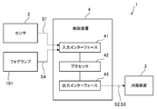
図2に例示されるように、センサシステム1は、制御装置4を備えうる。制御装置4は、入力インターフェース41、プロセッサ42、および出力インターフェース43を備えている。制御装置4は、車両100における適宜の位置に搭載されうる。
前述のように、センサ2は、検出された情報に対応するセンサ信号S1を出力する。入力インターフェース41は、センサ2から出力されたセンサ信号S1を受け付ける。入力インターフェース41は、センサ信号S1をプロセッサ42により行なわれる処理に適した形態に変換する信号処理回路を、必要に応じて含みうる。
プロセッサ42は、センサ2から受け付けたセンサ信号S1に基づいて消霧装置3の動作を制御するように構成されている。具体的には、プロセッサ42は、センサ信号S1(あるいは対応する情報)の品質に有意な劣化が認められるかを判断する。「有意な劣化」とは、所望の信号レベルや信号波形が得られなくなった状態を意味する。プロセッサ42は、センサ信号S1の品質に有意な劣化が認められた場合、消霧装置3を起動させる制御信号S2を生成する。
プロセッサ42は、出力インターフェース43から制御信号S2を出力する。消霧装置3は、制御信号S2を受け付けると、前述の消霧動作を実行する。出力インターフェース43は、制御信号S2を消霧装置3による処理に適した形態に変換する信号処理回路を、必要に応じて含みうる。
このような構成によれば、センサ2による情報検出能力の低下を抑制するための消霧動作を自動化できる。
プロセッサ42は、入力インターフェース41が受け付けるセンサ信号S1の品質を監視し続ける。消霧装置3の動作によってセンサ信号S1の品質に回復が認められた場合、プロセッサ42は、消霧装置3の動作を停止させる制御信号S3を生成し、出力インターフェース43から出力する。出力インターフェース43は、制御信号S3を消霧装置3による処理に適した形態に変換する信号処理回路を、必要に応じて含みうる。消霧装置3は、制御信号S3を受け付けると、消霧動作を停止する。
これに加えてあるいは代えて、入力インターフェース41は、車両100に搭載されたフォグランプ101が点灯されたことを示す点灯信号S4を受け付けうる。この場合、入力インターフェース41は、点灯信号S4をプロセッサ42により行なわれる処理に適した形態に変換する信号処理回路を、必要に応じて含みうる。
プロセッサ42は、フォグランプ101の点消灯に連動して消霧装置3の動作を制御するように構成されうる。具体的には、プロセッサ42は、入力インターフェース41が点灯信号S4を受け付けると、消霧装置3を起動させる制御信号S2を生成し、出力インターフェース43から出力する。消霧装置3は、制御信号S2を受け付けると、前述の消霧動作を実行する。
フォグランプ101が点灯されている場合、霧が発生している蓋然性が高い。したがって、フォグランプ101の点灯に連動して消霧装置3が起動されるように構成されることにより、センサ2による情報検出能力の低下を抑制するための消霧動作を自動化できる。
フォグランプ101が消灯されると、点灯信号S4が消失する。この場合、プロセッサ42は、消霧装置3の動作を停止させる制御信号S3を生成し、出力インターフェース43から出力する。消霧装置3は、制御信号S3を受け付けると、消霧動作を停止する。
上記の処理を実行可能なプロセッサ42は、汎用メモリと協働して動作する汎用マイクロプロセッサとして提供されてもよいし、専用集積回路素子の一部として提供されてもよい。汎用マイクロプロセッサとしては、CPU、MPU、GPUなどが例示されうる。汎用メモリとしては、RAMやROMが例示されうる。専用集積回路素子としては、マイクロコントローラ、ASIC、FPGAなどが例示されうる。
上記の実施形態は、本開示の理解を容易にするための例示にすぎない。上記の実施形態に係る構成は、本開示の趣旨を逸脱しなければ、適宜に変更や改良がなされうる。
図1を参照しつつ、車両100の少なくとも前方に位置する領域の情報に係るセンサ2の検出能力の低下を抑制するための消霧動作について説明した。同図に例示されるように、センサ2は、車両100の少なくとも後方に位置する領域の情報を検出するように配置されうる。この場合、図示を省略するが、消霧装置3は、車両100の少なくとも後方に位置するセンサ2の検出領域の少なくとも一部へ向けて、水、化合物、温風、荷電微粒子、超音波、および赤外線の少なくとも一つを供給するように構成される。
本開示の一部を構成するものとして、2019年3月20日に提出された日本国特許出願2019-052838号の内容が援用される。
Claims (5)
- 車両に搭載されるセンサシステムであって、
前記車両の外部の情報に対応する信号を出力するセンサと、
前記センサの検出領域の少なくとも一部へ向けて水、化合物、温風、荷電微粒子、超音波、および赤外線の少なくとも一つを供給する消霧装置と、
を備えている、
センサシステム。 - 前記化合物は、塩化ナトリウム、塩化カルシウム、およびヨウ化銀の少なくとも一つを含んでいる、
請求項1に記載のセンサシステム。 - 前記信号に基づいて前記消霧装置を起動させるプロセッサを備えている、
請求項1または2に記載のセンサシステム。 - フォグランプの点灯に連動して前記消霧装置を起動させるプロセッサを備えている、
請求項1から3のいずれか一項に記載のセンサシステム。 - 前記センサは、LiDARセンサ、カメラ、ミリ波レーダ、および超音波センサの少なくとも一つを含んでいる、
請求項1から4のいずれか一項に記載のセンサシステム。
Priority Applications (3)
| Application Number | Priority Date | Filing Date | Title |
|---|---|---|---|
| JP2021507218A JPWO2020189369A1 (ja) | 2019-03-20 | 2020-03-09 | |
| CN202080022271.0A CN113613964A (zh) | 2019-03-20 | 2020-03-09 | 传感器系统 |
| US17/440,889 US20220161762A1 (en) | 2019-03-20 | 2020-03-09 | Sensor system |
Applications Claiming Priority (2)
| Application Number | Priority Date | Filing Date | Title |
|---|---|---|---|
| JP2019052838 | 2019-03-20 | ||
| JP2019-052838 | 2019-03-20 |
Publications (1)
| Publication Number | Publication Date |
|---|---|
| WO2020189369A1 true WO2020189369A1 (ja) | 2020-09-24 |
Family
ID=72520324
Family Applications (1)
| Application Number | Title | Priority Date | Filing Date |
|---|---|---|---|
| PCT/JP2020/009991 Ceased WO2020189369A1 (ja) | 2019-03-20 | 2020-03-09 | センサシステム |
Country Status (4)
| Country | Link |
|---|---|
| US (1) | US20220161762A1 (ja) |
| JP (1) | JPWO2020189369A1 (ja) |
| CN (1) | CN113613964A (ja) |
| WO (1) | WO2020189369A1 (ja) |
Families Citing this family (1)
| Publication number | Priority date | Publication date | Assignee | Title |
|---|---|---|---|---|
| DE102023005258A1 (de) | 2023-01-25 | 2024-07-25 | Mercedes-Benz Group AG | Radarbaugruppe für Fahrzeuge |
Citations (6)
| Publication number | Priority date | Publication date | Assignee | Title |
|---|---|---|---|---|
| JP2000273835A (ja) * | 1999-03-24 | 2000-10-03 | Mitsubishi Electric Corp | 霧消去システム |
| JP2005013017A (ja) * | 2003-06-23 | 2005-01-20 | Mitsubishi Heavy Ind Ltd | 気象制御方法 |
| JP2006227876A (ja) * | 2005-02-17 | 2006-08-31 | Denso Corp | 夜間画像による霧検出装置 |
| JP2009128236A (ja) * | 2007-11-26 | 2009-06-11 | Denso Corp | 霧検知装置及びその設置方法 |
| JP2013091966A (ja) * | 2011-10-25 | 2013-05-16 | Nihon Univ | 消霧方法及び装置 |
| JP2020021807A (ja) * | 2018-07-31 | 2020-02-06 | 太陽誘電株式会社 | 磁気結合型コイル部品 |
Family Cites Families (12)
| Publication number | Priority date | Publication date | Assignee | Title |
|---|---|---|---|---|
| AT393275B (de) * | 1985-11-29 | 1991-09-25 | Alkoto Ifjusag Egyesueles | Frostschutzmittel auf basis von melasseschlempe |
| US5180122A (en) * | 1991-05-10 | 1993-01-19 | Fmc Corporation | Apparatus for deicing |
| GB2401270A (en) * | 2003-04-29 | 2004-11-03 | Motorola Inc | Fog detection system |
| KR100698585B1 (ko) * | 2005-03-22 | 2007-03-22 | 주식회사 화흥도로안전씨스템 | 안개 방재 시스템 |
| JP5056919B2 (ja) * | 2009-09-29 | 2012-10-24 | 株式会社デンソー | 車載光学センサカバー及び車載光学センサ装置 |
| US20110178635A1 (en) * | 2010-01-20 | 2011-07-21 | Noel Wayne Anderson | Ice mitigating robot |
| CN201924318U (zh) * | 2010-11-24 | 2011-08-10 | 王家全 | 驱雾机动车 |
| KR102089106B1 (ko) * | 2013-06-19 | 2020-03-16 | 현대모비스 주식회사 | 안개 발생 여부 판단 방법 및 이를 위한 장치 |
| JP6402866B2 (ja) * | 2016-08-29 | 2018-10-10 | トヨタ自動車株式会社 | ウインドウガラス加熱装置 |
| JP2018104957A (ja) * | 2016-12-26 | 2018-07-05 | 株式会社ソディック | 自動車用の消霧装置 |
| US10986700B2 (en) * | 2017-03-09 | 2021-04-20 | Aptiv Technologies Limited | Sensor assembly with integral defroster/defogger |
| CN107967729A (zh) * | 2017-12-18 | 2018-04-27 | 重庆互兴科技有限公司 | 一种具有除雾功能的行车记录仪 |
-
2020
- 2020-03-09 US US17/440,889 patent/US20220161762A1/en not_active Abandoned
- 2020-03-09 CN CN202080022271.0A patent/CN113613964A/zh active Pending
- 2020-03-09 WO PCT/JP2020/009991 patent/WO2020189369A1/ja not_active Ceased
- 2020-03-09 JP JP2021507218A patent/JPWO2020189369A1/ja active Pending
Patent Citations (6)
| Publication number | Priority date | Publication date | Assignee | Title |
|---|---|---|---|---|
| JP2000273835A (ja) * | 1999-03-24 | 2000-10-03 | Mitsubishi Electric Corp | 霧消去システム |
| JP2005013017A (ja) * | 2003-06-23 | 2005-01-20 | Mitsubishi Heavy Ind Ltd | 気象制御方法 |
| JP2006227876A (ja) * | 2005-02-17 | 2006-08-31 | Denso Corp | 夜間画像による霧検出装置 |
| JP2009128236A (ja) * | 2007-11-26 | 2009-06-11 | Denso Corp | 霧検知装置及びその設置方法 |
| JP2013091966A (ja) * | 2011-10-25 | 2013-05-16 | Nihon Univ | 消霧方法及び装置 |
| JP2020021807A (ja) * | 2018-07-31 | 2020-02-06 | 太陽誘電株式会社 | 磁気結合型コイル部品 |
Also Published As
| Publication number | Publication date |
|---|---|
| US20220161762A1 (en) | 2022-05-26 |
| CN113613964A (zh) | 2021-11-05 |
| JPWO2020189369A1 (ja) | 2020-09-24 |
Similar Documents
| Publication | Publication Date | Title |
|---|---|---|
| US11912246B2 (en) | Vehicle sensor system, vehicle provided with the vehicle sensor system, and vehicle | |
| US10481271B2 (en) | Automotive lighting system for a vehicle | |
| US10328843B2 (en) | Driving assistance system with short-distance ranging | |
| US10504369B2 (en) | Signal device and collision avoidance system | |
| US20200300964A1 (en) | Sensor system | |
| JPWO2019181766A1 (ja) | 車両用クリーナシステム | |
| US8946990B1 (en) | Vehicle headlight detection system | |
| US20130274999A1 (en) | Vehicle safety illumination arrangement and method | |
| KR20100019034A (ko) | 차량 조명 시스템 | |
| JPWO2019176607A1 (ja) | 車両用クリーナシステムおよび車両用システム | |
| EP2999207B1 (en) | Vehicle optical sensor system | |
| CN102998678A (zh) | 用于探测在机动车的环境中的物体的方法 | |
| JP7236800B2 (ja) | 車両洗浄システム | |
| WO2020189369A1 (ja) | センサシステム | |
| JPWO2020031685A1 (ja) | センサシステム | |
| US12216230B2 (en) | Sensor system | |
| JP2023144129A (ja) | センサシステム | |
| JP7820300B2 (ja) | 車載用センシングシステムおよびゲーティングカメラ | |
| JP2887697B2 (ja) | 車間距離検知・警報装置におけるレーザレーダの光軸調整方式 | |
| JP7496017B2 (ja) | センサシステム | |
| JPH08184675A (ja) | 車間距離警報装置 | |
| JP2008056135A (ja) | 車両用注意喚起システム | |
| JP7557523B2 (ja) | センサシステム、制御装置、非一時的なコンピュータ可読媒体、およびコンピュータプログラム | |
| WO2020017491A1 (ja) | センサシステム | |
| JP2591416Y2 (ja) | 車間距離検知・警報装置 |
Legal Events
| Date | Code | Title | Description |
|---|---|---|---|
| 121 | Ep: the epo has been informed by wipo that ep was designated in this application |
Ref document number: 20773927 Country of ref document: EP Kind code of ref document: A1 |
|
| ENP | Entry into the national phase |
Ref document number: 2021507218 Country of ref document: JP Kind code of ref document: A |
|
| NENP | Non-entry into the national phase |
Ref country code: DE |
|
| 122 | Ep: pct application non-entry in european phase |
Ref document number: 20773927 Country of ref document: EP Kind code of ref document: A1 |