WO2020189240A1 - 太陽電池モジュール及び太陽電池モジュールの製造方法 - Google Patents
太陽電池モジュール及び太陽電池モジュールの製造方法 Download PDFInfo
- Publication number
- WO2020189240A1 WO2020189240A1 PCT/JP2020/008715 JP2020008715W WO2020189240A1 WO 2020189240 A1 WO2020189240 A1 WO 2020189240A1 JP 2020008715 W JP2020008715 W JP 2020008715W WO 2020189240 A1 WO2020189240 A1 WO 2020189240A1
- Authority
- WO
- WIPO (PCT)
- Prior art keywords
- solar cell
- wiring member
- electrode portion
- bus bar
- cell module
- Prior art date
- Legal status (The legal status is an assumption and is not a legal conclusion. Google has not performed a legal analysis and makes no representation as to the accuracy of the status listed.)
- Ceased
Links
Images









Classifications
-
- H—ELECTRICITY
- H10—SEMICONDUCTOR DEVICES; ELECTRIC SOLID-STATE DEVICES NOT OTHERWISE PROVIDED FOR
- H10F—INORGANIC SEMICONDUCTOR DEVICES SENSITIVE TO INFRARED RADIATION, LIGHT, ELECTROMAGNETIC RADIATION OF SHORTER WAVELENGTH OR CORPUSCULAR RADIATION
- H10F19/00—Integrated devices, or assemblies of multiple devices, comprising at least one photovoltaic cell covered by group H10F10/00, e.g. photovoltaic modules
- H10F19/90—Structures for connecting between photovoltaic cells, e.g. interconnections or insulating spacers
-
- H—ELECTRICITY
- H10—SEMICONDUCTOR DEVICES; ELECTRIC SOLID-STATE DEVICES NOT OTHERWISE PROVIDED FOR
- H10F—INORGANIC SEMICONDUCTOR DEVICES SENSITIVE TO INFRARED RADIATION, LIGHT, ELECTROMAGNETIC RADIATION OF SHORTER WAVELENGTH OR CORPUSCULAR RADIATION
- H10F71/00—Manufacture or treatment of devices covered by this subclass
-
- H—ELECTRICITY
- H10—SEMICONDUCTOR DEVICES; ELECTRIC SOLID-STATE DEVICES NOT OTHERWISE PROVIDED FOR
- H10F—INORGANIC SEMICONDUCTOR DEVICES SENSITIVE TO INFRARED RADIATION, LIGHT, ELECTROMAGNETIC RADIATION OF SHORTER WAVELENGTH OR CORPUSCULAR RADIATION
- H10F77/00—Constructional details of devices covered by this subclass
- H10F77/20—Electrodes
-
- Y—GENERAL TAGGING OF NEW TECHNOLOGICAL DEVELOPMENTS; GENERAL TAGGING OF CROSS-SECTIONAL TECHNOLOGIES SPANNING OVER SEVERAL SECTIONS OF THE IPC; TECHNICAL SUBJECTS COVERED BY FORMER USPC CROSS-REFERENCE ART COLLECTIONS [XRACs] AND DIGESTS
- Y02—TECHNOLOGIES OR APPLICATIONS FOR MITIGATION OR ADAPTATION AGAINST CLIMATE CHANGE
- Y02E—REDUCTION OF GREENHOUSE GAS [GHG] EMISSIONS, RELATED TO ENERGY GENERATION, TRANSMISSION OR DISTRIBUTION
- Y02E10/00—Energy generation through renewable energy sources
- Y02E10/50—Photovoltaic [PV] energy
-
- Y—GENERAL TAGGING OF NEW TECHNOLOGICAL DEVELOPMENTS; GENERAL TAGGING OF CROSS-SECTIONAL TECHNOLOGIES SPANNING OVER SEVERAL SECTIONS OF THE IPC; TECHNICAL SUBJECTS COVERED BY FORMER USPC CROSS-REFERENCE ART COLLECTIONS [XRACs] AND DIGESTS
- Y02—TECHNOLOGIES OR APPLICATIONS FOR MITIGATION OR ADAPTATION AGAINST CLIMATE CHANGE
- Y02P—CLIMATE CHANGE MITIGATION TECHNOLOGIES IN THE PRODUCTION OR PROCESSING OF GOODS
- Y02P70/00—Climate change mitigation technologies in the production process for final industrial or consumer products
- Y02P70/50—Manufacturing or production processes characterised by the final manufactured product
Definitions
- the present invention relates to a solar cell module and a method for manufacturing a solar cell module.
- a see-through solar cell module capable of transmitting a part of sunlight in the thickness direction. Since this see-through solar cell module can transmit light, it is used as a translucent building material such as a window (for example, Patent Document 1).
- a conventional see-through solar cell module solar cells having a large light-receiving surface area are spread over the solar cells, and the space between adjacent solar cells is used for daylighting.
- the see-through solar cell module has a power generation part and a daylighting part, and since the light received by the power generation part of the solar cell is used, the power generation part is darker than the daylighting part.
- Conventional see-through solar cell modules usually have a large power generation portion to ensure sufficient power generation efficiency. Therefore, when the conventional see-through solar cell module is used as a translucent building material such as a window, the power generation portion becomes darker and more conspicuous than the lighting portion, and the design is impaired by the power generation portion. ..
- the present inventor has prototyped a solar cell module using a large number of solar cells having a small power generation portion in order to make the power generation portion of the solar cell inconspicuous. That is, a solar cell panel capable of generating electricity by itself is subdivided into strips by folding, and these solar cell cells are connected by an interconnector to form a solar cell string, and these solar cell strings are arranged in a plane. Then, a solar cell module connected by a wiring member was prototyped. In the prototype solar cell module, a large number of small pieces of solar cells are arranged side by side, and even if the power generation part becomes dark, the interval between the daylighting parts becomes narrow. Therefore, in the prototype solar cell module, the light wraps around from the daylighting part, and the power generation part is less noticeable than before.
- the finger electrode 702 is exposed on the cut surface.
- a part of the finger electrode 702 may protrude from the end face.
- the solar cell 701 is connected by an interconnector 703 as shown in FIG. 22B, and the finger electrode 702 projects when the solar cell string 705 is formed. The portion may come into direct contact with the interconnector 703, resulting in a short circuit.
- an object of the present invention is to provide a solar cell module capable of preventing a short circuit due to contact between a finger electrode portion and a wiring member and a method for manufacturing the same.
- One aspect of the present invention derived from the above considerations is to have a solar cell and a wiring member connecting the solar cell to another solar cell, and the solar cell has a width.
- the solar cell extends in a predetermined direction, and the solar cell has a bus bar electrode portion extending in the width direction and a plurality of finger electrode portions extending in the longitudinal direction from the bus bar electrode portion, and the finger electrode portion is the bus bar.
- the wiring member has a terminal electrode portion extending from the electrode portion to the end portion in the longitudinal direction of the solar cell, and the wiring member is connected to the bus bar electrode portion via a conductive adhesive, and when viewed in a plan view, the wiring member It is a solar cell module that extends so as to overlap the terminal electrode portion and includes an insulating protective material that covers the end face of the solar cell so that the end portion of the terminal electrode portion is buried.
- the insulating protective material is formed on the end face of the solar cell so that the end portion of the terminal electrode portion of the finger electrode portion is buried, the end portion of the terminal electrode portion of the finger electrode portion is a wiring member. Can be prevented from coming into direct contact with.
- a preferable aspect is that a part of the terminal electrode portion projects from the longitudinal end portion of the solar cell, and the overhanging portion of the terminal electrode portion is embedded in the insulating protective material.
- a preferred aspect is that it has a colored layer of a color different from that of the wiring member, the colored layer covers a part of the wiring member, and the wiring member is partially covered with the colored layer.
- the portion between the solar cell to be connected and the other solar cell is colored by the colored layer to a color closer to the color of the solar cell than the color of the wiring member. That is.
- a more preferable aspect is that the colored layer is provided so as to straddle the wiring member and the solar cell.
- the wiring member has an exposed portion exposed from the colored layer, and the exposed portion is connected to the bus bar electrode portion via a conductive adhesive.
- the colored layer is composed of the insulating protective material.
- the preferred aspect is that the wiring member overlaps with the terminal electrode portions of the plurality of finger electrode portions when viewed in a plan view.
- One aspect of the present invention has a plurality of finger electrode portions arranged side by side in the width direction and a bus bar electrode portion extending in the width direction to connect the plurality of finger electrode portions, and is connected to an external load for photoelectric conversion.
- a method for manufacturing a solar cell module using a possible in-process solar cell panel wherein the in-process solar cell panel is cut so that an intermediate portion in the longitudinal direction of the finger electrode portion is divided into a plurality of solar cell cells.
- This is a method for manufacturing a solar cell module, which comprises a wiring connection step of connecting one end side of a wiring member to the bus bar electrode portion of the solar cell of the above via a conductive adhesive.
- the insulating protective material is applied to the end face of the solar cell so that the longitudinal end of the finger electrode portion is buried, the longitudinal end of the finger electrode portion comes into direct contact with the wiring member. Can be prevented.
- a preferred aspect is that in the cell division step, the in-process solar cell panel is divided into the plurality of solar cells by folding.
- a preferred aspect is the second wiring connection step of connecting the other end side of the wiring member to another solar cell, and the portion of the wiring member between the one solar cell and the other solar cell.
- This includes a coloring step of applying a coloring material having a color closer to the color of the solar cell than the color of the wiring member.
- the insulating protective material is colored in a color closer to the color of the solar cell than the color of the wiring member, and the coating step is performed after the wiring connecting step. In the coating step, the insulating protective material is applied across the wiring member and the end faces of the solar cell.
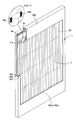
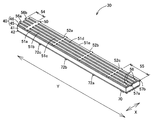
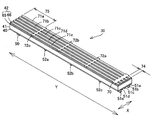
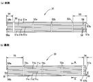
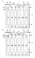
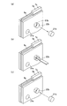
- FIG. 1 It is a perspective view which shows typically the installation state of the solar cell module of 1st Embodiment of this invention. It is a partially cutaway perspective view around the solar cell module of FIG. It is an exploded perspective view of the solar cell module of FIG. It is a top view of the solar cell module of FIG. 1, and the first translucent substrate is omitted. It is an electric circuit diagram of the solar cell module of FIG. It is explanatory drawing of the solar cell module of FIG. 1, (a) is the sectional view of the spare solar cell string, and (b) is the sectional view of the solar cell string on the power generation side. It is a perspective view of the solar cell of FIG. It is a perspective view which saw the solar cell of FIG. 7 from the direction different from FIG.
- FIG. 9 is an explanatory view of the solar cell of FIG. 9, FIG. 9A is a sectional view taken along the line AA of FIG. 9B, and FIG. 9B is a sectional view taken along the line BB of FIG. 9B.
- FIG. 4A and 4B are explanatory views of the interconnector
- FIG. 4A is a perspective view of a straight interconnector
- FIG. 4B is a perspective view of a folded interconnector. It is a perspective view around the linear interconnector of the solar cell module of FIG.
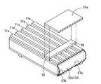
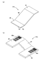
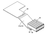
- FIG. C is a perspective view showing a state in which the lid portion is attached. It is a perspective view around the linear interconnector of the solar cell module of the 2nd Embodiment of this invention. It is explanatory drawing of the solar cell module prototyped by this inventor, (a) is the perspective view of the solar cell, and (b) is the perspective view of the solar cell string.
- the solar cell module 1 of the first embodiment of the present invention is mainly used as a wall building material such as a window, and is mainly attached to a frame member 100 fixed to a wall and vertically. It is used in a posture.
- the solar cell module 1 is a double-sided light receiving type see-through solar cell module, has a daylighting function, and is capable of transmitting a part of light in the thickness direction. Further, the solar cell module 1 is a double-sided light receiving type solar cell module capable of receiving light on both the front and back sides to generate electricity.
- the solar cell module 1 is managed by the management system 300 shown in FIG. 17 in each manufacturing process.
- the solar cell module 1 includes a main body 2 and terminal boxes 3a and 3b, and is illustrated via cable members 6a and 6b extending from the terminal boxes 3a and 3b. It is connected to the external load 150 shown in 5.
- the main body 2 includes a first translucent substrate 10 (first base material) and a second translucent substrate 11 (second base material) as main constituent members.
- the solar cell string 12 (series connection group), the first take-out wiring 14, the second take-out wiring 15, and the sealing materials 16a and 16b are provided.
- a plurality of solar cell strings 12 and take-out wirings 14 and 15 are arranged between the two translucent substrates 10 and 11, and the space between the translucent substrates 10 and 11 is sealed. It is filled with the materials 16a and 16b.
- the solar cell module 1 of the present embodiment is a double-sided light receiving type solar cell module, it has no front and back sides. However, in the following description, unless otherwise specified, the first translucent substrate 10 side is the front side. , The second translucent substrate 11 side will be described as the back side.
- the translucent substrates 10 and 11 are both plate-shaped members having a planar spread, and in the present embodiment, they have a quadrangular shape.
- the translucent substrates 10 and 11 are members having translucency and insulation, and for example, a translucent insulating substrate such as a glass substrate can be used.
- the first translucent substrate 10 is composed of a substrate main body 20 and lid members 21a to 21f.
- the substrate main body 20 has a plurality of through holes 22a to 22f penetrating in the thickness direction.
- the through holes 22a to 22f are work holes for cutting or connecting the take-out wiring 14 from the outside.
- the lid members 21a to 21f are members that close the through holes 22a to 22f, and have the same or similar shape to the opening shapes of the through holes 22a to 22f.
- the second translucent substrate 11 does not have through holes 22a to 22f.
- the solar cell string 12 includes a plurality of solar cells 30, interconnectors 31a and 31b (conductors), and a conductive adhesive 32 as main constituent members.
- the solar cell 30 is electrically and physically connected in series via the interconnectors 31a and 31b, and is composed of an insulating protective material 33 and a colored layer 34.
- the solar cell string 12 of the present embodiment meanders between the translucent substrates 10 and 11 when the first translucent substrate 10 is viewed in a plan view, and is as shown in FIG.
- one end in the extending direction is the positive electrode side end 35, and the other end is the negative electrode side end 36.
- the solar cell strings 12 of the present embodiment are electrically opened to the power generation side solar cell strings 37a to 37e electrically connected in parallel to the external load 150 and to the external load 150.
- the solar cell 30 is a piece of a solar cell obtained by cutting a work-in-progress solar cell panel 200 capable of generating electricity by connecting to an external load 150 into a strip shape, and is a vertically long rectangular piece. That is, as shown in FIG. 7, the solar cell 30 extends in the vertical direction Y with a width in the horizontal direction X. As shown in FIG. 10, the solar cell 30 of the present embodiment includes a first electrode layer 40, a photoelectric conversion unit 41, and a second electrode layer 42.
- the first electrode layer 40 is an electrode layer provided on the front side (first translucent substrate 10 side), and is composed of a base electrode layer 45 and a first collecting electrode 46.
- the base electrode layer 45 is an electrode layer that serves as a base for the first collecting electrode 46, and is a conductive layer that extracts electricity from the photoelectric conversion unit 41.
- the base electrode layer 45 of the present embodiment is made of a transparent conductive oxide such as indium tin oxide (ITO).
- ITO indium tin oxide
- the first collecting electrode 46 is a conductive layer partially laminated on the base electrode layer 45, and the bus bar electrode portion 50, the first finger electrode portions 51 (51a to 51e), and the first It is composed of two-finger electrode portions 52 (52a to 52c).
- the first collecting electrode 46 is made of a material having a higher conductivity than the base electrode layer 45, and in the present embodiment, it is made of a metal such as gold, silver, aluminum, copper, palladium, or a metal alloy thereof. ..
- the bus bar electrode portion 50 is an electrode portion that is provided unevenly distributed from one end portion of the center in the longitudinal direction (longitudinal direction Y) and extends in the width direction (horizontal direction X). As can be read from FIGS. 13 to 15, the bus bar electrode portion 50 is a portion that functions as a land to which the interconnectors 31a and 31b or the take-out wirings 14 and 15 are connected via the conductive adhesive material 32.
- the width of the bus bar electrode portion 50 is not particularly limited, but is preferably 1 mm or more and 8 mm or less.
- the first finger electrode portions 51a to 51e are linear portions extending from the intermediate portion of the bus bar electrode portion 50 in the lateral direction X toward both end portions in the longitudinal direction (longitudinal direction Y).
- the first finger electrode portions 51a to 51e are arranged in parallel at intervals in the horizontal direction X, and all reach the vicinity of the end portion in the vertical direction Y.
- the width of the first finger electrode portions 51a to 51e is narrower than the width of the bus bar electrode portion 50, and is preferably 30 ⁇ m or more and 70 ⁇ m or less.
- the first finger electrode portions 51a to 51e have terminal electrode portions 54 and 55 at both ends in the longitudinal direction (longitudinal direction Y).
- One terminal electrode portion 54 is a portion extending from the bus bar electrode portion 50 to one end portion in the longitudinal direction
- the other terminal electrode portion 55 is the second finger electrode portion farthest from the bus bar electrode portion 50 in the longitudinal direction. It is a portion extending from 52c to the other end in the longitudinal direction.
- the terminal electrode portion 54 has overhanging portions 56a and 56b protruding outward from the end portion of the base electrode layer 45
- the terminal electrode portion 55 has an overhanging portion 56a from the end portion of the base electrode layer 45.
- 56b has overhanging portions 57a and 57b overhanging toward the opposite side.
- overhanging portions 56a, 56b, 57a, 57b are rarely generated, and even if they occur, they hardly overhang.
- it is described as having the overhanging portions 56a, 56b, 57a, 57b, and is exaggerated.
- the terminal electrode portion 55 is provided with a position information display portion 58.
- the position information display unit 58 is a portion that displays information on each solar cell 30 and / or related information associated with the information on each solar cell 30, and is a work-in-progress solar panel as a division source shown in FIG. It is possible to directly or indirectly display the information of the 200 and the position information of the in-process solar cell panel 200 before the division.
- the position information display unit 58 of the present embodiment is composed of a part of the terminal electrode portions 55 of the plurality of first finger electrode portions 51a, 51b, 51d.
- the terminal electrode portions 55 of the predetermined first finger electrode portions 51a, 51b, 51d are provided with an overhanging portion in the lateral direction X, and the cutting position in the in-process solar cell panel 200 is determined by the overhanging position of the overhanging portion.
- Information is displayed. That is, the position of the position information display unit 58 is different in each solar cell 30, and the position information in the work-in-process solar panel 200 before division can be displayed depending on the positional relationship.
- the second finger electrode portions 52a to 52c are linear portions extending parallel to the bus bar electrode portion 50 and extending perpendicular to the first finger electrode portions 51a to 51e.
- the second finger electrode portions 52a to 52c are arranged in parallel at intervals in the vertical direction Y, and all reach the vicinity of the end portion in the horizontal direction X.
- the width of the second finger electrode portions 52a to 52c is narrower than the width of the bus bar electrode portion 50, and is preferably 30 ⁇ m or more and 70 ⁇ m or less.
- the photoelectric conversion unit 41 is a portion that converts light energy into electrical energy.
- the solar cell 30 of the present embodiment is a crystalline solar cell, in which the photoelectric conversion unit 41 has a semiconductor layer laminated on a semiconductor substrate, and has a PN junction between the semiconductor substrate and the semiconductor layer. ing.
- the second electrode layer 42 is an electrode layer that is paired with the first electrode layer 40 and is provided on the back side (second translucent substrate 11 side), and as shown in FIG. 10, the base electrode layer 65 and the second electrode layer 42 It is composed of a double electrode 66.
- the base electrode layer 65 is an electrode layer that serves as a base for the second collecting electrode 66, and is a conductive layer that extracts electricity from the photoelectric conversion unit 41.
- the base electrode layer 65 of the present embodiment is made of a transparent conductive oxide such as indium tin oxide (ITO).
- the second collecting electrode 66 is a conductive layer partially laminated on the base electrode layer 65, and as shown in FIG. 8, the bus bar electrode portion 70, the first finger electrode portions 71 (71a to 71e), and the first It is composed of two-finger electrode portions 72 (72a to 72c).
- the second collecting electrode 66 is made of a material having a higher conductivity than that of the base electrode layer 65, and in the present embodiment, it is made of a metal such as gold, silver, aluminum, copper, palladium, or a metal alloy thereof. ..
- the bus bar electrode portion 70 is an electrode portion that is provided unevenly distributed from one end portion of the center in the longitudinal direction (longitudinal direction Y) and extends in the width direction (horizontal direction X).
- the bus bar electrode portion 70 is provided on the side opposite to the bus bar electrode portion 50 of the first collecting electrode 46 in the longitudinal direction, and extends in the lateral direction X.
- the bus bar electrode portion 70 is a portion that functions as a land to which the take-out wirings 14 and 15 or the interconnectors 31a and 31b are connected via the conductive adhesive material 32.
- the width of the bus bar electrode portion 70 is not particularly limited, but is preferably 1 mm or more and 8 mm or less.
- the first finger electrode portions 71a to 71e are linear portions extending from the intermediate portion of the bus bar electrode portion 70 in the lateral direction X toward both end portions in the longitudinal direction (longitudinal direction Y).
- the first finger electrode portions 71a to 71e are arranged side by side at intervals in the lateral direction X (width direction), and all reach the vicinity of the end portion in the vertical direction Y.
- the width of the first finger electrode portions 71a to 71e is narrower than the width of the bus bar electrode portion 70, and is preferably 30 ⁇ m or more and 70 ⁇ m or less.
- the first finger electrode portions 71a to 71e have terminal electrode portions 74 and 75 at both ends in the longitudinal direction (longitudinal direction Y).
- One terminal electrode portion 74 is a portion extending from the bus bar electrode portion 70 to one end portion in the longitudinal direction
- the other terminal electrode portion 75 is the second finger electrode portion farthest from the bus bar electrode portion 70 in the longitudinal direction. It is a portion extending from 72c to the other end in the longitudinal direction.
- the second finger electrode portions 72a to 72c are linear portions extending parallel to the bus bar electrode portion 70 and extending orthogonally to the first finger electrode portions 71a to 71e.
- the second finger electrode portions 72a to 72c are arranged side by side at intervals in the vertical direction Y, and all of them reach the vicinity of the end portion in the horizontal direction X.
- the width of the second finger electrode portions 72a to 72c is narrower than the width of the bus bar electrode portion 70, and is preferably 30 ⁇ m or more and 70 ⁇ m or less.
- the interconnectors 31a and 31b are connecting members that electrically and physically connect the solar cells 30 and 30 adjacent to each other in the horizontal direction X or the vertical direction Y.
- the interconnector 31a is a linear interconnector that connects two adjacent solar cells 30 and 30 and linearly connects them in the vertical direction Y. As shown in FIG. 12A, the interconnector 31a includes a first connector portion 80, a second connector portion 81, and a first connection portion 82 that connects the connector portions 80 and 81.
- the interconnector 31b constitutes a folded portion of the solar cell string 12 when the first translucent substrate 10 is viewed in a plan view, and two solar cells adjacent to each other in the lateral direction X. It is a folded interconnector that connects 30 and 30.
- the interconnector 31b is a “U” -shaped connector in a plan view, and connects the third connector portion 85, the fourth connector portion 86, and the connector portions 85 and 86. It includes two connectors 87. That is, the third connector portion 85 and the fourth connector portion 86 extend in the same direction from both ends of the second connecting portion 87 when viewed in a plan view.
- the interconnector 31b is provided with information display units 88a and 88b on the third connector portion 85 and the fourth connector portion 86, and directly or indirectly transmits information on the solar cells 30 in each row connected by the interconnector 31a. It is possible to display the image.
- the information display units 88a and 88b are in-process solar cell panels that serve as a division source for each solar cell 30 in a row of solar cell 30 (hereinafter, also referred to as a solar cell row) connected in the vertical direction Y by an interconnector 31a. It is possible to directly or indirectly display the information of 200 and the solar cell information composed of the position information in the in-process solar cell panel 200 before the division of each solar cell 30 in the solar cell row.
- the information display units 88a and 88b of the present embodiment are one-dimensional codes or two-dimensional codes that are related information associated with the solar cell information, and are read by the reading unit 305 of the reading device 302 described later in each row. It is possible to read the information of the solar cell 30.
- the conductive adhesive material 32 electrically and physically connects the bus bar electrode portions 50 and 70 to the interconnectors 31a and 31b, or the bus bar electrode portions 50 and 70 and the take-out wiring 14 and 15. It is an adhesive material that has conductivity and adhesiveness.
- the conductive adhesive material 32 is a conductive adhesive film in which conductive adhesive materials are provided on both sides of the conductive film.
- the insulating protective material 33 has an insulating property, and is an insulating protective layer that covers and protects the end face of the solar cell 30 in the longitudinal direction as shown in FIG.
- the insulating protective material 33a is capable of burying the overhanging portions 56a and 56b of the terminal electrode portion 54 and preventing contact between the overhanging portions 56a and 56b and the interconnector 31a.
- the insulating protective material 33b is capable of burying the overhanging portions 57a and 57b of the terminal electrode portion 55 to prevent contact between the overhanging portions 57a and 57b and the interconnector 31b.
- the colored layer 34 is a layer colored in a color different from that of the interconnector 31a, and is a layer that covers a part of the interconnector 31a as shown in FIG.
- the colored layer 34 has a color similar to the color of the solar cell 30, and is colored to a color closer to the color of the solar cell 30 than the color of the interconnector 31a.
- the take-out wirings 14 and 15 are wirings for taking out electricity from each solar cell string 12 to the outside of the main body 2.
- the take-out wiring 14 is a positive electrode side wiring in which one end is connected to the positive electrode side end 35 of each solar cell string 12, and the other end is a cable member in the terminal box 3a. This is a wiring that is electrically connected to 6a.
- the take-out wiring 14 includes a main body wiring portion 90 connected to the terminal box 3a, and branch wiring portions 91a to 91f that branch from the end portion of the main body wiring portion 90 toward the positive electrode side end portion 35 of each solar cell string 12. ing.
- the branch wiring portion 91a connected to the spare solar cell string 38 is partially cut off, forming a disconnection portion 92 (disconnection portion). That is, the branch wiring portion 91a is divided into a main body wiring portion 90 side and a spare solar cell string 38 side.
- the take-out wiring 15 is a negative electrode side wiring in which one end is connected to the negative electrode side end 36 of each solar cell string 12, and the other end is a cable member in the terminal box 3b. It is a wiring that is electrically connected to 6b.
- the take-out wiring 15 includes a main body wiring portion 95 connected to the terminal box 3b, and branch wiring portions 96a to 96f branching from the end portion of the main body wiring portion 95 toward the negative electrode side end portion 36 of each solar cell string 12. ing.
- the sealing materials 16a and 16b are translucent adhesive materials that adhere between the translucent substrates 10 and 11 as shown in FIG. 6, and fill the space between the translucent substrates 10 and 11. It is intended to be sealed.
- the sealing materials 16a and 16b of the present embodiment are insulating resin sheets, and specifically, EVA (ethylene vinyl acetate copolymer resin) sheets.
- the terminal boxes 3a and 3b have the cable members 6a and 6b and the box portions 7a and 7b, and the take-out wiring 14 connected to the solar cell string 12 inside the box portions 7a and 7b. 15 is connected.
- each solar cell string 12 is arranged between the translucent substrates 10 and 11 and is embedded in the sealing materials 16a and 16b. As shown in FIG. 4, each solar cell string 12 extends in the vertical direction Y as a whole and is arranged in the horizontal direction X.
- the opening of the through hole 22a (spare side through hole) of the first translucent substrate 10 is connected to the spare solar cell string 38 when the first translucent substrate 10 is viewed in a plan view as shown in FIGS. 4 and 18. It overlaps with the disconnection portion 92 of the branch wiring portion 91a to be formed. That is, the disconnection portion 92 of the branch wiring portion 91a is arranged at a position where it is exposed from the through hole 22a when the lid member 21a is removed.
- the openings of the through holes 22b to 22f (power generation side through holes) of the first translucent substrate 10 are branch wirings connected to the power generation side solar cell strings 37a to 37e when the first translucent substrate 10 is viewed in a plan view. It overlaps with the parts 91b to 91f. That is, the branch wiring portions 91b to 91f are arranged at positions exposed from the through holes 22b to 22f when the lid members 21b to 21f are removed.
- the bus bar electrode portions 50 and 70 extend in the width direction (horizontal direction X) of the interconnectors 31a and 31b.
- the first connector portion 80 is connected to the bus bar electrode portion 50 of the first collection electrode 46 of one solar cell 30a via a conductive adhesive material 32.
- the two connector portions 81 are connected to the bus bar electrode portion 70 of the second collection electrode 66 of the other solar cell 30b via the conductive adhesive material 32.
- the first connector portion 80 overlaps with the terminal electrode portions 54 of the first finger electrode portions 51a to 51e of one solar cell 30a, and the second connector portion 81 is the other. It overlaps with the terminal electrode portions 74 of the first finger electrode portions 71a to 71e of the solar cell 30b.
- the linear interconnector 31a is covered with a colored layer 34 having a color different from that of the interconnector 31a on the outer surface, and an exposed portion 84 exposed from the colored layer 34 is partially formed.
- the exposed portion 84 of the linear interconnector 31a is connected to the bus bar electrode portions 50 and 70 via the conductive adhesive material 32. That is, the exposed portion 84 of the linear interconnector 31a is a conductive portion with the bus bar electrode portions 50 and 70.
- the portion between the solar cells 30 and 30 which is the connection target and is adjacent to the solar cell 30 in the vertical direction is a color closer to the color of the solar cell 30 than the color of the interconnectors 31a and 31b due to the coloring layer 34. It is colored in.
- the colored layer 34 is provided so as to straddle the solar cell 30 from the linear interconnector 31a.
- the folded interconnector 31b has a third connector portion 85 connected to the bus bar electrode portion 70 of the second collecting electrode 66 of one solar cell 30c via a conductive adhesive material 32.
- the 4 connector portion 86 is connected to the bus bar electrode portion 50 of the first collection electrode 46 of the other solar cell 30d via the conductive adhesive material 32.
- the third connector portion 85 overlaps with the terminal electrode portions 74 of the first finger electrode portions 71a to 71e of one solar cell 30c, and the fourth connector portion 86 is the other. It overlaps with the terminal electrode portions 54 of the first finger electrode portions 51a to 51e of the solar cell 30d.
- one end of the take-out wiring 14 is connected to the bus bar electrode portion 50 of the first collection electrode 46 of the solar cell 30 via a conductive adhesive material 32.
- the take-out wiring 14 overlaps the terminal electrode portions 54 of the first finger electrode portions 51a to 51e of the solar cell 30 with the vicinity of one end thereof.
- one end of the take-out wiring 15 is connected to the bus bar electrode portion 70 of the second collecting electrode 66 of the solar cell 30 via the conductive adhesive material 32.
- the take-out wiring 15 overlaps with the terminal electrode portions 74 of the first finger electrode portions 71a to 71e of the solar cell 30 in the vicinity of one end portion.
- the insulating protective material 33 covers the end face of the solar cell 30 so that the overhanging portions 56a, 56b, 57a, 57b of the first finger electrode portions 51b, 51d, 51b, 51e are buried.
- the position information display unit 58 of the solar cell 30 does not overlap with the interconnectors 31a and 31b, and is located at a position separated from the interconnectors 31a and 31b. That is, the position information display unit 58 is not hidden by the interconnectors 31a and 31b, but is exposed to the outside.
- the frame member 100 is a member that covers the four sides of the main body 2 and the terminal boxes 3a and 3b, and is a holding member having a square ring shape when viewed from the front.
- the frame member 100 includes a first covering portion 101 that covers the first translucent substrate 10 side of the main body portion 2 and a second covering portion that covers the second translucent substrate 11 side of the main body portion 2. It has an end face covering portion 103 that connects 102, the first covering portion 101 and the second covering portion 102, and covers the end surface of the main body portion 2, and has openings in each of the first covering portion 101 and the second covering portion 102. It includes 105a and 105b.
- the frame member 100 surrounds the terminal boxes 3a and 3b, and further covers each side of the main body 2.
- the frame member 100 straddles the through holes 22a to 22f and the lid members 21a to 21f so that the first covering portion 101 does not come off the lid members 21a to 21f from the through holes 22a to 22f. That is, the through holes 22a to 22b are hidden by the frame member 100 when viewed from the front and are substantially invisible.
- the in-process solar cell panel 200 is a solar cell panel that is a raw material for manufacturing the solar cell 30, and is a work-in-process product of the solar cell 30. As shown in FIG. 16A, the in-process solar cell panel 200 has bus bar electrode portions 201a and 201b, first finger electrode portions 202a, and second collecting electrodes 204a on one main surface (surface) side. The finger electrode portions 203a to 203c are provided, and a panel information display portion 205 is further provided.
- the in-process solar cell panel 200 has the bus bar electrode portions 201c and 201d and the first finger electrode portion 202b as the second collecting electrode 204b on the other main surface (back surface) side. It has second finger electrode portions 203d to 203f. Then, the in-process solar cell panel 200 is in-processed by connecting a wiring member (not shown) to each of the bus bar electrode portions 201a and 201b and the bus bar electrode portions 201c and 201d and connecting to the external load 150 via the wiring member. Although it is a product, it can generate electricity when it receives light such as sunlight.
- the bus bar electrode portion 201a is a portion that becomes the bus bar electrode portion 50 after the cutting process
- the bus bar electrode portion 201d is a portion that becomes the bus bar electrode portion 70.
- the first finger electrode portion 202a is a portion that becomes the first finger electrode portions 51a to 51e after the cutting process
- the first finger electrode portion 202b is a portion that becomes the first finger electrode portions 71a to 71e.
- the first finger electrode unit 202a is provided with a position information display unit 207 corresponding to the position information display unit 58 after cutting.
- the second finger electrode portions 203a to 203c are portions that become the second finger electrode portions 52a to 52c after cutting, and the second finger electrode portions 203d to 203f are portions with the second finger electrode portions 72a to 72c after cutting. It is a part that becomes.
- the panel information display unit 205 directly or indirectly displays the management information of the in-process solar cell panel 200.
- the panel information display unit 205 of the present embodiment is a two-dimensional code, and can display the information of the in-process solar cell panel 200 on an external device by reading it with an external terminal.
- control device 301 and the reading device 302 are connected wirelessly or by wire.
- control device 301 and the reading device 302 can communicate with each other via a network 303 such as the Internet or an intranet.
- the control device 301 includes a specific unit 310 (specific means), a collation unit 311, a storage unit 312, and an input / output unit 313.
- the collating unit 311 collates the information of the solar cell 30 in each row stored in advance in the storage unit 312 with the received information.
- the identification unit 310 can identify the solar cells 30 in each row.
- the reading device 302 includes a reading unit 305 and an input / output unit 306, and the reading unit 305 reads the information display units 88a and 88b provided on the interconnector 31b to read the interconnector 31a.
- Information on the solar cells 30 in each row connected by the above can be transmitted to the control device 301.
- a work-in-process solar cell forming step of forming a work-in-process solar cell panel 200 capable of photoelectric conversion by connecting to an external load 150 is performed.
- the production of the work-in-process solar cell panel 200 formed in the work-in-process solar cell forming step is almost the same as that of the conventional solar cell panel and is known, so this step will be briefly described.
- a semiconductor layer is formed on both sides of the semiconductor substrate by using a CVD device or the like to form a photoelectric conversion unit 41, and base electrode layers 45 and 65 are formed on both sides of the photoelectric conversion unit 41 by using a CVD device or the like. Then, the collector electrodes 204a and 204b are formed on the base electrode layers 45 and 65 by screen printing or the like to form the in-process solar cell panel 200.
- the panel information display unit 205 and the position information display unit 207 are formed on the front side. Further, the control device 301 of the management system 300 associates the position information display unit 207 of each solar cell 30 with the divided position in the in-process solar cell panel 200 and stores them in the storage unit 312, and the position information display unit 207 self. The split positions of the solar cell 30 and the in-process solar panel 200 can be collated. At this time, if necessary, the in-process solar cell panel 200 is connected to the external load 150 via a wiring member to measure the power generation characteristics, and it is confirmed from the power generation characteristics whether the in-process solar cell panel 200 is a defective product. May be good.
- a solar cell string step of forming the solar cell string 12 is performed. Specifically, as shown by the two-point chain line in FIG. 16, the in-process solar cell panel 200 is cut so that the intermediate portion in the longitudinal direction of the first finger electrode portions 202a and 202b is divided, and the plurality of solar cell cells 30 are formed.
- the solar cell 30 is formed (cell division step, solar cell formation step). Specifically, it is divided at equal intervals in the horizontal direction X, and the inner portion of the bus bar electrode portion 201b and the outer portion of the bus bar electrode portion 201a so as to include the position information display portion 207 of the in-process solar cell panel 200 in the vertical direction Y. Is divided into each.
- the dividing method is not particularly limited, but in the present embodiment, it is divided by so-called folding, and a laser is irradiated from the second electrode layer 42 side to the semiconductor substrate of the photoelectric conversion unit 41. It is divided by making a groove) and bending it along the cut (groove).
- a fluid insulating protective material 33 is applied to the longitudinal end of the divided solar cell 30, and as shown in FIG. 11, the overhanging portions 56a, 56b, 57a of the first finger electrode portions 51a to 51e are applied. , 57b is buried in the insulating protective material 33 (coating step).
- one end side of the interconnectors 31a and 31b is connected to the bus bar electrode portion 50 of one solar cell 30 via the conductive adhesive material 32 (wiring connection step), and the bus bar electrode portion of another solar cell 30 is further connected.
- the other ends of the interconnectors 31a and 31b are connected to 70 (second wiring connection step).
- the wiring connection step may be performed at the same time as the second wiring connection step, or may be performed before the second wiring connection step.
- a fluid coloring material is applied to the portion between one solar cell 30 and the other solar cell 30 of the linear interconnector 31a, and the color is closer to the color of the solar cell 30 than the color of the linear interconnector 31a.
- the colored layer 34 of the above is formed (coloring step). At this time, the coloring material is applied to the exposed portion of the linear interconnector 31a, and further applied from the linear interconnector 31a to the solar cell 30 to be cured.
- the information display units 88a and 88b are formed on the connector portions 85 and 86 of the folded interconnector 31b as shown in FIG. 12 (b). Then, the position information display unit 58 of each solar cell 30 collates the division position on the in-process solar cell panel 200, and the positions of the information display units 88a and 88b and each solar cell 30 and the division in the in-process solar cell panel 200 are collated. Link the positions (information display unit forming process).
- the take-out wirings 14 and 15 are connected to the solar cell strings 12, and the solar cell strings 12 are electrically connected to the terminal boxes 3a and 3b.
- the sealing material 16a is sandwiched between the two translucent substrates 10 and 11. , 16b.
- the repair method of the solar cell module 1 of the first embodiment will be described.
- the power generation side solar cell string 37a has an abnormality due to a failure or the like.
- the branch wiring portion 91b connected to the failed power generation side solar cell string 37a is cut. Specifically, as shown in FIG. 19A, the lid member 21b overlapping the branch wiring portion 91b is removed, and as shown in FIG. 19B, a dedicated jig is inserted from the through hole 22b to cut the branch wiring portion 91b. Then, it is cut off in the through hole 22b.
- the lid member 21b is reattached to the through hole 22b to close the through hole 22b. That is, the lid member 21b is covered so as to cover the cut portion of the branch wiring portion 91b.
- the connecting lid member 110 is provided with a conductive foil 111 (connecting member) on the portion on the solar cell 30 side, and the conductive foil 111 connects the broken portion 92 of the branch wiring portion 91a. That is, as shown in FIG. 18B, the conductive foil 111 of the connecting lid member 110 electrically connects the portion of the branch wiring portion 91a on the solar cell 30 side and the portion on the main body wiring portion 90 side.
- the conductive foil 111 of the connecting lid member 110 is not particularly limited as long as it has conductivity.
- a metal such as gold, silver, copper, platinum, palladium, or a metal alloy can be used.
- each power generation side solar cell string 37a is electrically opened to the external load 150 outside the sealing materials 16a and 16b.
- the spare solar cell string 38 can be electrically connected to the external load 150. Therefore, even if one power generation side solar cell string 37a does not generate power due to a failure or the like, the power generation side solar cell string 37a is electrically opened to the external load 150 as shown in FIG. By connecting the solar cell string 38 to the external load 150, it is possible to generate power with the power generation capacity as designed.
- the branch wiring portions 91b to 91f of the solar cell strings 37a to 37e on the power generation side are exposed from the openings of the through holes 22b to 22f on the power generation side, and the spare solar cell strings 38
- the disconnection portion 92 is exposed from the opening of the spare side through hole 22a. Therefore, by cutting a part of one branch wiring portion 91b and electrically connecting the disconnection portion 92 of the branch wiring portion 91a, the solar cell string 12 used for power generation can be easily connected from the power generation side solar cell string 37a. It can be changed to the spare solar cell string 38.
- the solar cell is embedded so that the overhanging portions 56a, 56b, 57a, 57b forming the ends of the terminal electrode portions 54, 55 of the first finger electrode portions 51a to 51e are buried.
- An insulating protective material 33 is formed on the end face of the cell 30. Therefore, it is possible to prevent the overhanging portions 56a, 56b, 57a, 57b forming the ends of the terminal electrode portions 54, 55 of the first finger electrode portions 51a to 51e from directly contacting the interconnectors 31a, 31b.
- a part of the interconnector 31a is covered with a colored layer 34 that is closer to the color of the solar cell 30 than the interconnector 31a. Therefore, the color of the interconnector 31a can be brought closer to that of the solar cell 30, and the color of the interconnector 31a is less noticeable.
- the colored layer 34 is provided so as to straddle the interconnector 31a and the solar cell 30. Therefore, the colored layer 34 also functions as an adhesive between the interconnector 31a and the solar cell 30, and the interconnector 31a is hard to peel off from the solar cell 30.
- the information display units 88a and 88b are associated with the solar cell information. Since the information is displayed, it is possible to identify the relationship between the specific solar cell 30b in which the defect has occurred and the in-process solar cell panel 200. Therefore, it is easy to give feedback such as identifying the cause of the defect.
- the information display units 88a and 88b can be visually recognized through the first translucent substrate 10 and the sealing material 16a from the outside in the thickness direction with reference to the solar cell 30. Is. Therefore, the positions of the information display units 88a and 88b can be easily confirmed, and the information display units 88a and 88b can be read by the reading unit 305 from the outside of the first translucent substrate 10.
- each solar cell 30 is provided with a position information display unit 58 for displaying the position information of the in-process solar cell panel 200 before division. ing. Therefore, the position information of the solar cell 30 can be specified even after the interconnectors 31a and 31b are removed from the solar cell 30.
- the position information display unit 58 is formed at a position deviated from the linear interconnector 31a. Therefore, even when the straight line interconnector 31a is connected, the position information display unit 58 can be visually recognized, and the position information in the in-process solar cell panel 200 before the division of the solar cell 30 can be specified.
- the solar cell module looks substantially the same as before the repair in appearance.
- the reading unit 305 reads the related information from the information display units 88a and 88b of the solar cell module 1 to the solar cell information, and the specific unit 310 reads the related information from the related information. Can be identified. Therefore, a large number of solar cell modules 1 can be collectively managed at the time of manufacturing. Further, even when a defect such as an initial defect occurs in the specific solar cell 30b, the relationship between the specific solar cell 30b and the in-process solar cell panel 200 can be specified. Therefore, it is easy to give feedback such as identifying the cause of the defect.
- the solar cell module of the second embodiment of the present invention will be described.
- the same components as those of the solar cell module 1 of the first embodiment are designated by the same reference numerals, and the description thereof will be omitted.
- the solar cell string 612 of the second embodiment includes a plurality of solar cell cells 30, interconnectors 31a and 31b, a conductive adhesive 32, and a colored protective layer 633 as main components. It is configured.
- the colored protective layer 633 has an insulating property and is colored in a color different from that of the interconnector 31a.
- the color protective layer 633 has a color similar to the color of the solar cell 30, and is colored closer to the color of the solar cell 30 than the color of the interconnector 31a. That is, the colored protective layer 633 has both the function as the insulating protective material 33 and the function as the colored layer 34 of the first embodiment.
- the colored protective layer 633 is provided on the front side and the back side of the interconnector 31a, straddling the end face of one solar cell 30e, on the interconnector 31a, and the end face of the other solar cell 30f. ..
- the in-process solar cell panel 200 is cut so that the intermediate portion in the longitudinal direction of the first finger electrode portions 202a and 202b is divided, and the solar cell panel 200 is divided into a plurality of solar cell cells 30. (Cell division process).
- one end side of the interconnectors 31a and 31b is connected to the bus bar electrode portion 50 of one solar cell 30f via the conductive adhesive material 32 (wiring connection step), and the bus bar electrode of another solar cell 30e is further connected.
- the other ends of the interconnectors 31a and 31b are connected to the portion 70 (second wiring connection step).
- a colored protective material (insulating protective material) having fluidity is applied from the end face of one solar cell 30 over the interconnector 31a and the other solar cell 30 to form the colored protective layer 633, and the figure is shown.
- the overhanging portions 56a, 56b, 57a, 57b of the first finger electrode portions 51a to 51e are embedded in the colored protective layer 633 (coating step). That is, the colored protective material is applied to the exposed portion of the linear interconnector 31a, and further applied from the end face of one solar cell 30 to the top of the other solar cell 30 and cured.
- the colored protective layer 633 has a function as an insulating protective material 33 and a function as a colored layer 34, the cost can be reduced.
- the coating step is performed after the wiring connection step, and a colored protective material that also serves as an insulating protective material is applied across the end faces of the interconnector 31a and the solar cell 30. .. Therefore, the manufacturing process can be simplified.
- the solar cell string 12 in which the abnormality has occurred is removed from the other solar cell string 12 by cutting a part of the take-out wiring 14 connected to the solar cell string 12 in which the abnormality has occurred during repair.
- the present invention is not limited to this.
- the interconnectors 31a and 31b constituting the abnormal solar cell string 12 may be disconnected to electrically disconnect the abnormal solar cell string 12 from the other solar cell string 12.
- the solar cells 30 are arranged in the vertical direction Y, but the present invention is not limited to this.
- the solar cells 30 may be arranged in the horizontal direction X or may be arranged in the oblique direction.
- the disconnection portion 92 is provided in the take-out wiring 14 connected to the positive electrode side end portion 35 of the spare solar cell string 38, but the present invention is not limited to this.
- a disconnection portion 92 may be provided in the take-out wiring 15 connected to the negative electrode side end portion 36 of the spare solar cell string 38.
- the solar cell 30 has a vertically long rectangular shape, but the present invention is not limited to this, and the shape of the solar cell 30 is not particularly limited.
- the solar cell 30 may have a substantially square shape as in the conventional case, or may have a polygonal shape such as a triangle, a quadrangle, a pentagon, or a hexagon. Further, it may be circular or elliptical.
- the conductive adhesive material 32 is adhered only on the bus bar electrode portions 50 and 70, but the present invention is not limited to this.
- the conductive adhesive 32 may be provided over the first finger electrode portions 51, 71 and the base electrode layers 45, 65 from above the bus bar electrode portions 50, 70 toward the outer end portion.
- connection lid member 110 electrically connects the disconnection portion 92 with the conductive foil 111, but the present invention is not limited to this, and the disconnection portion 92 is electrically connected.
- the shape of the connecting member is not particularly limited.
- the connecting member may be plate-shaped or linear.
Landscapes
- Photovoltaic Devices (AREA)
Abstract
本発明は、フィンガー電極部(71a~71e)と配線部材(31a)との接触による短絡を防止可能な太陽電池モジュール及びその製造方法を提供する。太陽電池セルと、太陽電池セルと他の太陽電池セルを接続する配線部材(31a)を有し、太陽電池セルは、幅をもって所定の方向に延びるものであり、太陽電池セルは、幅方向に延びるバスバー電極部(70)と、バスバー電極部(70)から長手方向に延びる複数のフィンガー電極部(71a~71e)を有し、フィンガー電極部(71a~71e)は、バスバー電極部(70)から太陽電池セルの長手方向の端部まで至る末端電極部を有し、配線部材(31a)は、バスバー電極部(70)に対して導電性接着材(32)を介して接続され、平面視したときに末端電極部と重なるように延びており、末端電極部の端部が埋没するように太陽電池セルの端面を覆う絶縁保護材(33)を備えている構成とする。
Description
本発明は、太陽電池モジュール及び太陽電池モジュールの製造方法に関する。
従来から、太陽光の一部を厚み方向に透過可能なシースルー太陽電池モジュールが知られている。このシースルー太陽電池モジュールは、光が透過可能であるため、窓等の透光性の建材としての用途で使用されている(例えば、特許文献1)。
従来のシースルー太陽電池モジュールは、受光面の面積が大きい太陽電池セルを敷き詰めており、隣接する太陽電池セルの間の空間を利用して採光している。
従来のシースルー太陽電池モジュールは、受光面の面積が大きい太陽電池セルを敷き詰めており、隣接する太陽電池セルの間の空間を利用して採光している。
シースルー太陽電池モジュールは、発電部分と採光部分があり、太陽電池セルの発電部分で受光した光を使用するため、発電部分が採光部分に比べて暗くなる。従来のシースルー太陽電池モジュールは、通常、十分な発電効率を確保するべく発電部分を大きく形成する。そのため、従来のシースルー太陽電池モジュールは、窓等の透光性の建材として使用したときに、採光部分に比べて発電部分が暗くなって目立ってしまい、当該発電部分により意匠性が損なわれていた。
そこで、本発明者は、太陽電池セルの発電部分を目立たなくするべく、発電部分が小さい太陽電池セルを多数用いた太陽電池モジュールを試作した。すなわち、自己で発電可能な太陽電池パネルを折り割により短冊状に細分化し、これらの太陽電池セルをインターコネクタで接続することで太陽電池ストリングを形成し、これらの太陽電池ストリングを面状に配置し、配線部材で接続した太陽電池モジュールを試作した。
試作した太陽電池モジュールは、多数の小片状の太陽電池セルを並べており、発電部分が暗くなっても採光部分の間隔が狭くなる。そのため、試作した太陽電池モジュールは、採光部分から光が回り込み、従来に比べて発電部分が目立たなくすることに成功した。
試作した太陽電池モジュールは、多数の小片状の太陽電池セルを並べており、発電部分が暗くなっても採光部分の間隔が狭くなる。そのため、試作した太陽電池モジュールは、採光部分から光が回り込み、従来に比べて発電部分が目立たなくすることに成功した。
しかしながら、試作した太陽電池モジュールには、新たな問題が発生した。
すなわち、レーザーを照射して溝を形成し、当該溝に沿って折り曲げて分割する、いわゆる折り割により、既存の太陽電池パネルから太陽電池セル701を細分化すると、切断面にフィンガー電極702が露出し、図22(a)のように、フィンガー電極702の一部が端面から張り出すものが生じてしまう場合がある。
フィンガー電極702の一部が端面から張り出すと、図22(b)のように太陽電池セル701間をインターコネクタ703で接続し、太陽電池ストリング705を形成する際に、フィンガー電極702の張出部分がインターコネクタ703に直接接触してしまい、短絡する場合が生じていた。
すなわち、レーザーを照射して溝を形成し、当該溝に沿って折り曲げて分割する、いわゆる折り割により、既存の太陽電池パネルから太陽電池セル701を細分化すると、切断面にフィンガー電極702が露出し、図22(a)のように、フィンガー電極702の一部が端面から張り出すものが生じてしまう場合がある。
フィンガー電極702の一部が端面から張り出すと、図22(b)のように太陽電池セル701間をインターコネクタ703で接続し、太陽電池ストリング705を形成する際に、フィンガー電極702の張出部分がインターコネクタ703に直接接触してしまい、短絡する場合が生じていた。
そこで、本発明は、フィンガー電極部と配線部材との接触による短絡を防止可能な太陽電池モジュール及びその製造方法を提供することを目的とする。
上記した考察のもとに導き出された本発明の一つの様相は、太陽電池セルと、前記太陽電池セルと他の太陽電池セルを接続する配線部材を有し、前記太陽電池セルは、幅をもって所定の方向に延びるものであり、前記太陽電池セルは、幅方向に延びるバスバー電極部と、前記バスバー電極部から長手方向に延びる複数のフィンガー電極部を有し、前記フィンガー電極部は、前記バスバー電極部から前記太陽電池セルの長手方向の端部まで至る末端電極部を有し、前記配線部材は、前記バスバー電極部に対して導電性接着材を介して接続され、平面視したときに前記末端電極部と重なるように延びており、前記末端電極部の端部が埋没するように前記太陽電池セルの端面を覆う絶縁保護材を備えている、太陽電池モジュールである。
本様相によれば、フィンガー電極部の末端電極部の端部が埋没するように太陽電池セルの端面を絶縁保護材が形成されているため、フィンガー電極部の末端電極部の端部が配線部材に直接接触することを防止できる。
好ましい様相は、前記末端電極部は、一部が前記太陽電池セルの長手方向の端部から張り出しており、前記末端電極部の張出部分が前記絶縁保護材に埋没していることである。
好ましい様相は、前記配線部材とは異なる色の着色層を有し、前記着色層は、前記配線部材の一部を覆うものであり、前記配線部材は、一部が前記着色層で被覆され、平面視したときに、接続する前記太陽電池セルと前記他の太陽電池セルとの間の部分が前記着色層によって前記配線部材の色よりも前記太陽電池セルの色に近い色に着色されていることである。
より好ましい様相は、前記着色層は、前記配線部材と前記太陽電池セルに跨って設けられていることである。
より好ましい様相は、前記配線部材は、前記着色層から露出した露出部を有し、前記露出部は、前記バスバー電極部に対して導電性接着材を介して接続されていることである。
より好ましい様相は、前記着色層は、前記絶縁保護材によって構成されていることである。
好ましい様相は、前記配線部材は、平面視したときに、前記複数のフィンガー電極部の末端電極部と重なっていることである。
本発明の一つの様相は、幅方向に並設された複数のフィンガー電極部と、幅方向に延び前記複数のフィンガー電極部を接続するバスバー電極部をもち、外部負荷に接続することで光電変換可能な仕掛太陽電池パネルを使用する太陽電池モジュールの製造方法であって、前記フィンガー電極部の長手方向の中間部が分割されるように前記仕掛太陽電池パネルを切断し、複数の太陽電池セルに分割するセル分割工程と、分割された一の太陽電池セルにおいて前記フィンガー電極部の長手方向の端部が埋没するように前記太陽電池セルの端面に絶縁保護材を塗布する塗布工程と、前記一の太陽電池セルの前記バスバー電極部に対して導電性接着材を介して配線部材の一端側を接続する配線接続工程を含む、太陽電池モジュールの製造方法である。
本様相によれば、フィンガー電極部の長手方向の端部が埋没するように太陽電池セルの端面に絶縁保護材を塗布するため、フィンガー電極部の長手方向の端部が配線部材に直接接触することを防止できる。
好ましい様相は、前記セル分割工程では、折り割によって前記仕掛太陽電池パネルを前記複数の太陽電池セルに分割することである。
好ましい様相は、他の太陽電池セルに前記配線部材の他端側を接続する第2配線接続工程と、前記配線部材の前記一の太陽電池セルと前記他の太陽電池セルの間の部分に前記配線部材の色よりも前記太陽電池セルの色に近い色の着色材を塗布する着色工程を含むことである。
好ましい様相は、前記絶縁保護材は、前記配線部材の色よりも前記太陽電池セルの色に近い色に着色されており、前記塗布工程は、前記配線接続工程よりも後に行うものであり、前記塗布工程において、前記配線部材及び前記太陽電池セルの端面に跨って前記絶縁保護材を塗布することである。
本発明の太陽電池モジュール及び太陽電池モジュールの製造方法によれば、フィンガー電極部と配線部材との接触による短絡を防止できる。
以下、本発明の実施形態について詳細に説明する。
本発明の第1実施形態の太陽電池モジュール1は、図1のように、主に窓等の壁面建材として使用されるものであり、主に壁に固定される枠部材100に取り付けられ、縦姿勢で使用されるものである。
太陽電池モジュール1は、両面受光型のシースルー太陽電池モジュールであり、採光機能をもち、一部の光を厚み方向に透過可能となっている。また、太陽電池モジュール1は、表裏の両面で受光して発電可能な両面受光型の太陽電池モジュールである。
太陽電池モジュール1は、各製造工程において、図17に示される管理システム300によって管理されるものである。
太陽電池モジュール1は、両面受光型のシースルー太陽電池モジュールであり、採光機能をもち、一部の光を厚み方向に透過可能となっている。また、太陽電池モジュール1は、表裏の両面で受光して発電可能な両面受光型の太陽電池モジュールである。
太陽電池モジュール1は、各製造工程において、図17に示される管理システム300によって管理されるものである。
太陽電池モジュール1は、図2~図4のように、本体部2と、端子ボックス3a,3bを備えており、端子ボックス3a,3bから延設されたケーブル部材6a,6bを介して、図5に示される外部負荷150に対して接続されるものである。
本体部2は、図4,図6のように、主要構成部材として、第1透光性基板10(第1基材)と、第2透光性基板11(第2基材)と、複数の太陽電池ストリング12(直列接続群)と、第1取出配線14と、第2取出配線15と、封止材16a,16bを備えている。そして、本体部2は、2枚の透光性基板10,11の間に、複数の太陽電池ストリング12と取出配線14,15が配されて、透光性基板10,11の間が封止材16a,16bで充填されたものである。
本実施形態の太陽電池モジュール1は、両面受光型の太陽電池モジュールであるため、表裏がないが、以下の説明においては形式上、特に断りのない限り、第1透光性基板10側を表側、第2透光性基板11側を裏側として説明する。
透光性基板10,11は、図3のように、ともに面状に広がりをもつ板状部材であり、本実施形態では四角形状をしている。透光性基板10,11は、透光性及び絶縁性を有する部材であり、例えば、ガラス基板等の透光性絶縁基板が使用できる。
第1透光性基板10は、図3のように、基板本体20と、蓋部材21a~21fで構成されている。
基板本体20は、厚み方向に貫通した複数の貫通孔22a~22fを有している。
貫通孔22a~22fは、外部から取出配線14を切断又は接続するための作業孔である。
蓋部材21a~21fは、貫通孔22a~22fを閉塞する部材であり、貫通孔22a~22fの開口形状と同一又は相似形状をしている。
基板本体20は、厚み方向に貫通した複数の貫通孔22a~22fを有している。
貫通孔22a~22fは、外部から取出配線14を切断又は接続するための作業孔である。
蓋部材21a~21fは、貫通孔22a~22fを閉塞する部材であり、貫通孔22a~22fの開口形状と同一又は相似形状をしている。
一方、第2透光性基板11は、第1透光性基板10と異なり、貫通孔22a~22fが形成されていない。
太陽電池ストリング12は、図3,図11,図13~図15のように、主要構成部材として、複数の太陽電池セル30と、インターコネクタ31a,31b(導電体)と、導電性接着材32と、絶縁保護材33と、着色層34とで構成され、各太陽電池セル30がインターコネクタ31a,31bを介して電気的及び物理的に直列接続されたものである。
本実施形態の太陽電池ストリング12は、図3のように、第1透光性基板10を平面視したときに、透光性基板10,11間を蛇行して延びており、図5のように、延び方向の一方の端部が正極側端部35となっており、他方の端部が負極側端部36となっている。
本実施形態の太陽電池ストリング12は、図3のように、第1透光性基板10を平面視したときに、透光性基板10,11間を蛇行して延びており、図5のように、延び方向の一方の端部が正極側端部35となっており、他方の端部が負極側端部36となっている。
本実施形態の太陽電池ストリング12は、図5のように、外部負荷150に対して電気的に並列接続された発電側太陽電池ストリング37a~37eと、外部負荷150に対して電気的に開放された予備太陽電池ストリング38がある。すなわち、本実施形態の太陽電池モジュール1は、発電時に発電に寄与しない予備太陽電池ストリング38を実装している。
太陽電池セル30は、外部負荷150に接続することで発電可能な仕掛太陽電池パネル200を短冊状に裁断した太陽電池片であり、縦長長方形状の小片である。すなわち、太陽電池セル30は、図7のように、横方向Xに幅をもって縦方向Yに延びるものである。
本実施形態の太陽電池セル30は、図10のように、第1電極層40と、光電変換部41と、第2電極層42を備えている。
本実施形態の太陽電池セル30は、図10のように、第1電極層40と、光電変換部41と、第2電極層42を備えている。
第1電極層40は、表側(第1透光性基板10側)に設けられた電極層であり、下地電極層45と、第1集電極46で構成されている。
下地電極層45は、第1集電極46の下地となる電極層であり、光電変換部41から電気を取り出す導電層である。本実施形態の下地電極層45は、インジウム錫酸化物(ITO)等の透明導電性酸化物で構成されている。
第1集電極46は、図7のように、下地電極層45上を部分的に積層された導電層であり、バスバー電極部50と、第1フィンガー電極部51(51a~51e)と、第2フィンガー電極部52(52a~52c)で構成されている。
第1集電極46は、下地電極層45よりも導電率が高い材料で形成されており、本実施形態では、金、銀、アルミニウム、銅、パラジウム等の金属又はその金属合金で構成されている。
下地電極層45は、第1集電極46の下地となる電極層であり、光電変換部41から電気を取り出す導電層である。本実施形態の下地電極層45は、インジウム錫酸化物(ITO)等の透明導電性酸化物で構成されている。
第1集電極46は、図7のように、下地電極層45上を部分的に積層された導電層であり、バスバー電極部50と、第1フィンガー電極部51(51a~51e)と、第2フィンガー電極部52(52a~52c)で構成されている。
第1集電極46は、下地電極層45よりも導電率が高い材料で形成されており、本実施形態では、金、銀、アルミニウム、銅、パラジウム等の金属又はその金属合金で構成されている。
バスバー電極部50は、図7のように、長手方向(縦方向Y)の中央よりも片側端部よりに偏在して設けられ、幅方向(横方向X)に延びる電極部である。
バスバー電極部50は、図13~図15から読み取れるように、導電性接着材32を介してインターコネクタ31a,31b又は取出配線14,15が接続されるランドとして機能する部位である。
バスバー電極部50の幅は、特に限定されるものではないが、1mm以上8mm以下であることが好ましい。
バスバー電極部50は、図13~図15から読み取れるように、導電性接着材32を介してインターコネクタ31a,31b又は取出配線14,15が接続されるランドとして機能する部位である。
バスバー電極部50の幅は、特に限定されるものではないが、1mm以上8mm以下であることが好ましい。
第1フィンガー電極部51a~51eは、図7のように、バスバー電極部50の横方向Xの中間部から長手方向(縦方向Y)の両端部側に向けて延びる線状部位である。
第1フィンガー電極部51a~51eは、横方向Xに間隔を空けて並列されており、いずれも縦方向Yの端部近傍まで至っている。
第1フィンガー電極部51a~51eの幅は、バスバー電極部50の幅よりも狭くなっており、30μm以上70μm以下であることが好ましい。
第1フィンガー電極部51a~51eは、横方向Xに間隔を空けて並列されており、いずれも縦方向Yの端部近傍まで至っている。
第1フィンガー電極部51a~51eの幅は、バスバー電極部50の幅よりも狭くなっており、30μm以上70μm以下であることが好ましい。
第1フィンガー電極部51a~51eは、図7のように、長手方向(縦方向Y)の両端部に末端電極部54,55を有している。
一方の末端電極部54は、バスバー電極部50から長手方向の一方の端部まで至る部位であり、他方の末端電極部55は、バスバー電極部50から長手方向に最も離れた第2フィンガー電極部52cから長手方向の他方の端部まで至る部位である。
末端電極部54は、下地電極層45の端部から外側に向けて張り出した張出部56a,56bを有しており、末端電極部55は、下地電極層45の端部から張出部56a,56bとは反対側に向けて張り出した張出部57a,57bを有している。
なお、実際には、張出部56a,56b,57a,57bが生じるのは、稀であり、生じてもほとんど張り出ない。しかしながら、本実施形態では、本発明の説明の都合上、張出部56a,56b,57a,57bがあるものとして説明し、誇張して表現する。
一方の末端電極部54は、バスバー電極部50から長手方向の一方の端部まで至る部位であり、他方の末端電極部55は、バスバー電極部50から長手方向に最も離れた第2フィンガー電極部52cから長手方向の他方の端部まで至る部位である。
末端電極部54は、下地電極層45の端部から外側に向けて張り出した張出部56a,56bを有しており、末端電極部55は、下地電極層45の端部から張出部56a,56bとは反対側に向けて張り出した張出部57a,57bを有している。
なお、実際には、張出部56a,56b,57a,57bが生じるのは、稀であり、生じてもほとんど張り出ない。しかしながら、本実施形態では、本発明の説明の都合上、張出部56a,56b,57a,57bがあるものとして説明し、誇張して表現する。
末端電極部55には、図7のように、位置情報表示部58が設けられている。
位置情報表示部58は、各太陽電池セル30の情報及び/又は各太陽電池セル30の情報に関連付けられた関連情報を表示する部位であり、図16に示される分割元となる仕掛太陽電池パネル200の情報と、分割前の仕掛太陽電池パネル200における位置情報を直接又は間接的に表示可能となっている。
本実施形態の位置情報表示部58は、図9のように、複数の第1フィンガー電極部51a,51b,51dの末端電極部55の一部で構成されている。
具体的には、所定の第1フィンガー電極部51a,51b,51dの末端電極部55に横方向Xの張出部分を設け、当該張出部分の張出位置によって仕掛太陽電池パネル200における切断位置の情報を表示している。すなわち、各太陽電池セル30で位置情報表示部58の位置が異なっており、その位置関係によって分割前の仕掛太陽電池パネル200における位置情報を表示可能となっている。
位置情報表示部58は、各太陽電池セル30の情報及び/又は各太陽電池セル30の情報に関連付けられた関連情報を表示する部位であり、図16に示される分割元となる仕掛太陽電池パネル200の情報と、分割前の仕掛太陽電池パネル200における位置情報を直接又は間接的に表示可能となっている。
本実施形態の位置情報表示部58は、図9のように、複数の第1フィンガー電極部51a,51b,51dの末端電極部55の一部で構成されている。
具体的には、所定の第1フィンガー電極部51a,51b,51dの末端電極部55に横方向Xの張出部分を設け、当該張出部分の張出位置によって仕掛太陽電池パネル200における切断位置の情報を表示している。すなわち、各太陽電池セル30で位置情報表示部58の位置が異なっており、その位置関係によって分割前の仕掛太陽電池パネル200における位置情報を表示可能となっている。
第2フィンガー電極部52a~52cは、図9(a)のように、バスバー電極部50と平行に延び、第1フィンガー電極部51a~51eに対して直交するように延びる線状部位である。
第2フィンガー電極部52a~52cは、縦方向Yに間隔を空けて並列されており、いずれも横方向Xの端部近傍まで至っている。
第2フィンガー電極部52a~52cの幅は、いずれもバスバー電極部50の幅よりも狭くなっており、30μm以上70μm以下であることが好ましい。
第2フィンガー電極部52a~52cは、縦方向Yに間隔を空けて並列されており、いずれも横方向Xの端部近傍まで至っている。
第2フィンガー電極部52a~52cの幅は、いずれもバスバー電極部50の幅よりも狭くなっており、30μm以上70μm以下であることが好ましい。
光電変換部41は、光エネルギーを電気エネルギーに変換する部位である。
本実施形態の太陽電池セル30は、結晶型の太陽電池セルであり、光電変換部41が半導体基板上に半導体層が積層したものであり、半導体基板と半導体層の間でPN接合を有している。
本実施形態の太陽電池セル30は、結晶型の太陽電池セルであり、光電変換部41が半導体基板上に半導体層が積層したものであり、半導体基板と半導体層の間でPN接合を有している。
第2電極層42は、第1電極層40と対をなし、裏側(第2透光性基板11側)に設けられた電極層であり、図10のように、下地電極層65と、第2集電極66で構成されている。
下地電極層65は、第2集電極66の下地となる電極層であり、光電変換部41から電気を取り出す導電層である。本実施形態の下地電極層65は、インジウム錫酸化物(ITO)等の透明導電性酸化物で構成されている。
第2集電極66は、下地電極層65上を部分的に積層された導電層であり、図8のように、バスバー電極部70と、第1フィンガー電極部71(71a~71e)と、第2フィンガー電極部72(72a~72c)で構成されている。
第2集電極66は、下地電極層65よりも導電率が高い材料で形成されており、本実施形態では、金、銀、アルミニウム、銅、パラジウム等の金属又はその金属合金で構成されている。
第2集電極66は、下地電極層65よりも導電率が高い材料で形成されており、本実施形態では、金、銀、アルミニウム、銅、パラジウム等の金属又はその金属合金で構成されている。
バスバー電極部70は、長手方向(縦方向Y)の中央よりも片側端部よりに偏在して設けられ、幅方向(横方向X)に延びる電極部である。バスバー電極部70は、長手方向において第1集電極46のバスバー電極部50とは反対側に設けられ、横方向Xに延びている。
バスバー電極部70は、導電性接着材32を介して取出配線14,15又はインターコネクタ31a,31bが接続されるランドとして機能する部位である。
バスバー電極部70の幅は、特に限定されるものではないが、1mm以上8mm以下であることが好ましい。
バスバー電極部70は、導電性接着材32を介して取出配線14,15又はインターコネクタ31a,31bが接続されるランドとして機能する部位である。
バスバー電極部70の幅は、特に限定されるものではないが、1mm以上8mm以下であることが好ましい。
第1フィンガー電極部71a~71eは、図8のように、バスバー電極部70の横方向Xの中間部から長手方向(縦方向Y)の両端部側に向けて延びる線状部位である。
第1フィンガー電極部71a~71eは、横方向X(幅方向)に間隔を空けて並設されており、いずれも縦方向Yの端部近傍まで至っている。
第1フィンガー電極部71a~71eの幅は、バスバー電極部70の幅よりも狭くなっており、30μm以上70μm以下であることが好ましい。
第1フィンガー電極部71a~71eは、横方向X(幅方向)に間隔を空けて並設されており、いずれも縦方向Yの端部近傍まで至っている。
第1フィンガー電極部71a~71eの幅は、バスバー電極部70の幅よりも狭くなっており、30μm以上70μm以下であることが好ましい。
第1フィンガー電極部71a~71eは、図9(b)のように、長手方向(縦方向Y)の両端部に末端電極部74,75を有している。
一方の末端電極部74は、バスバー電極部70から長手方向の一方の端部まで至る部位であり、他方の末端電極部75は、バスバー電極部70から長手方向に最も離れた第2フィンガー電極部72cから長手方向の他方の端部まで至る部位である。
一方の末端電極部74は、バスバー電極部70から長手方向の一方の端部まで至る部位であり、他方の末端電極部75は、バスバー電極部70から長手方向に最も離れた第2フィンガー電極部72cから長手方向の他方の端部まで至る部位である。
第2フィンガー電極部72a~72cは、バスバー電極部70と平行に延び、第1フィンガー電極部71a~71eに対して直交するように延びる線状部位である。
第2フィンガー電極部72a~72cは、縦方向Yに間隔を空けて並設されており、いずれも横方向Xの端部近傍まで至っている。
第2フィンガー電極部72a~72cの幅は、いずれもバスバー電極部70の幅よりも狭くなっており、30μm以上70μm以下であることが好ましい。
第2フィンガー電極部72a~72cは、縦方向Yに間隔を空けて並設されており、いずれも横方向Xの端部近傍まで至っている。
第2フィンガー電極部72a~72cの幅は、いずれもバスバー電極部70の幅よりも狭くなっており、30μm以上70μm以下であることが好ましい。
インターコネクタ31a,31bは、図4のように、横方向X又は縦方向Yに隣接する太陽電池セル30,30間を電気的及び物理的に接続する接続部材である。
インターコネクタ31aは、図12(a),図13のように、隣接する2つの太陽電池セル30,30間を接続し、縦方向Yに直線的に接続する直線インターコネクタである。
インターコネクタ31aは、図12(a)のように、第1コネクター部80と、第2コネクター部81と、コネクター部80,81間を接続する第1接続部82を備えている。
インターコネクタ31aは、図12(a)のように、第1コネクター部80と、第2コネクター部81と、コネクター部80,81間を接続する第1接続部82を備えている。
インターコネクタ31bは、図3,図4のように、第1透光性基板10を平面視したときに、太陽電池ストリング12の折り返し部分を構成し、横方向Xに隣接する2つの太陽電池セル30,30間を接続する折り返しインターコネクタである。
インターコネクタ31bは、図12(b)のように、平面視「コ」字状のコネクタであり、第3コネクター部85と、第4コネクター部86と、コネクター部85,86間を接続する第2接続部87を備えている。すなわち、第3コネクター部85と第4コネクター部86は、平面視したときに、第2接続部87の両端部から同じ方向に延びている。
インターコネクタ31bは、図12(b)のように、平面視「コ」字状のコネクタであり、第3コネクター部85と、第4コネクター部86と、コネクター部85,86間を接続する第2接続部87を備えている。すなわち、第3コネクター部85と第4コネクター部86は、平面視したときに、第2接続部87の両端部から同じ方向に延びている。
インターコネクタ31bには、第3コネクター部85及び第4コネクター部86に情報表示部88a,88bが設けられており、インターコネクタ31aで接続される各列の太陽電池セル30の情報を直接又は間接的に表示する可能となっている。
情報表示部88a,88bは、インターコネクタ31aで縦方向Yに接続された太陽電池セル30の列(以下、太陽電池セル列ともいう)における各太陽電池セル30の分割元となる仕掛太陽電池パネル200の情報、及び太陽電池セル列における各太陽電池セル30の分割前の仕掛太陽電池パネル200における位置情報で構成される太陽電池セル情報を直接又は間接的に表示可能となっている。
本実施形態の情報表示部88a,88bは、太陽電池セル情報に紐付けされた関連情報たる一次元コード又は二次元コードであり、後述する読取装置302の読取部305で読み取ることによって各列の太陽電池セル30の情報を読み取ることが可能となっている。
情報表示部88a,88bは、インターコネクタ31aで縦方向Yに接続された太陽電池セル30の列(以下、太陽電池セル列ともいう)における各太陽電池セル30の分割元となる仕掛太陽電池パネル200の情報、及び太陽電池セル列における各太陽電池セル30の分割前の仕掛太陽電池パネル200における位置情報で構成される太陽電池セル情報を直接又は間接的に表示可能となっている。
本実施形態の情報表示部88a,88bは、太陽電池セル情報に紐付けされた関連情報たる一次元コード又は二次元コードであり、後述する読取装置302の読取部305で読み取ることによって各列の太陽電池セル30の情報を読み取ることが可能となっている。
導電性接着材32は、図13~図15のように、バスバー電極部50,70とインターコネクタ31a,31b、又はバスバー電極部50,70と取出配線14,15を電気的及び物理的に接続する接着材であり、導電性及び接着性を有している。
本実施形態では、導電性接着材32は、導電性フィルムの両面に導電性粘着材が設けられた導電性接着フィルムである。
本実施形態では、導電性接着材32は、導電性フィルムの両面に導電性粘着材が設けられた導電性接着フィルムである。
絶縁保護材33は、絶縁性を有し、図11のように、太陽電池セル30の長手方向の端面を被覆して保護する絶縁保護層である。
絶縁保護材33aは、末端電極部54の張出部56a,56bを埋没させ、張出部56a,56bとインターコネクタ31aとの接触を防止可能となっている。また、絶縁保護材33bは、末端電極部55の張出部57a,57bを埋没させ、張出部57a,57bとインターコネクタ31bとの接触を防止可能となっている。
絶縁保護材33aは、末端電極部54の張出部56a,56bを埋没させ、張出部56a,56bとインターコネクタ31aとの接触を防止可能となっている。また、絶縁保護材33bは、末端電極部55の張出部57a,57bを埋没させ、張出部57a,57bとインターコネクタ31bとの接触を防止可能となっている。
着色層34は、インターコネクタ31aとは異なる色に着色された層であって、図13のようにインターコネクタ31aの一部を覆う層である。
着色層34は、太陽電池セル30の色と同系色であって、インターコネクタ31aの色よりも太陽電池セル30の色に近い色に着色されている。
着色層34は、太陽電池セル30の色と同系色であって、インターコネクタ31aの色よりも太陽電池セル30の色に近い色に着色されている。
取出配線14,15は、図4,図5のように、各太陽電池ストリング12から本体部2の外部に電気を取り出す配線である。
取出配線14は、図5のように、一方の端部が各太陽電池ストリング12の正極側端部35に接続される正極側配線であって、他方の端部が端子ボックス3a内でケーブル部材6aと電気的に接続される配線である。
取出配線14は、端子ボックス3aに接続される本体配線部90と、本体配線部90の端部から各太陽電池ストリング12の正極側端部35に向かって分岐する分岐配線部91a~91fを備えている。
分岐配線部91a~91fのうち、予備太陽電池ストリング38に接続される分岐配線部91aは、一部が切断されており、断線部92(断線部分)を構成している。すなわち、分岐配線部91aは、本体配線部90側と、予備太陽電池ストリング38側に分割されている。
取出配線14は、図5のように、一方の端部が各太陽電池ストリング12の正極側端部35に接続される正極側配線であって、他方の端部が端子ボックス3a内でケーブル部材6aと電気的に接続される配線である。
取出配線14は、端子ボックス3aに接続される本体配線部90と、本体配線部90の端部から各太陽電池ストリング12の正極側端部35に向かって分岐する分岐配線部91a~91fを備えている。
分岐配線部91a~91fのうち、予備太陽電池ストリング38に接続される分岐配線部91aは、一部が切断されており、断線部92(断線部分)を構成している。すなわち、分岐配線部91aは、本体配線部90側と、予備太陽電池ストリング38側に分割されている。
取出配線15は、図5のように、一方の端部が各太陽電池ストリング12の負極側端部36に接続される負極側配線であって、他方の端部が端子ボックス3b内でケーブル部材6bと電気的に接続される配線である。
取出配線15は、端子ボックス3bに接続される本体配線部95と、本体配線部95の端部から各太陽電池ストリング12の負極側端部36に向かって分岐する分岐配線部96a~96fを備えている。
取出配線15は、端子ボックス3bに接続される本体配線部95と、本体配線部95の端部から各太陽電池ストリング12の負極側端部36に向かって分岐する分岐配線部96a~96fを備えている。
封止材16a,16bは、透光性を有し、図6のように透光性基板10,11間を接着する透光性接着材であって、透光性基板10,11間を充填し封止するものである。
本実施形態の封止材16a,16bは、絶縁樹脂シートであり、具体的には、EVA(エチレン酢酸ビニル共重合樹脂)シートである。
本実施形態の封止材16a,16bは、絶縁樹脂シートであり、具体的には、EVA(エチレン酢酸ビニル共重合樹脂)シートである。
端子ボックス3a,3bは、図3のように、ケーブル部材6a,6bと箱部7a,7bを有するものであり、箱部7a,7bの内部で太陽電池ストリング12に接続された取出配線14,15が接続されるものである。
続いて、本実施形態の太陽電池モジュール1の各部材の位置関係について説明する。
透光性基板10,11は、図3のように、対面するように配されており、対向する2面に封止材16a,16bが積層されている。そして、各太陽電池ストリング12は、透光性基板10,11の間に配されており、封止材16a,16bに埋没されている。
各太陽電池ストリング12は、図4のように、全体として縦方向Yに延び、横方向Xに並んでいる。
各太陽電池ストリング12は、図4のように、全体として縦方向Yに延び、横方向Xに並んでいる。
第1透光性基板10の貫通孔22a(予備側貫通孔)の開口は、図4,図18のように、第1透光性基板10を平面視したときに予備太陽電池ストリング38に接続される分岐配線部91aの断線部92と重なっている。すなわち、分岐配線部91aの断線部92は、蓋部材21aを外したときに貫通孔22aから露出する位置に配されている。
第1透光性基板10の貫通孔22b~22f(発電側貫通孔)の開口は、第1透光性基板10を平面視したときに発電側太陽電池ストリング37a~37eに接続される分岐配線部91b~91fと重なっている。すなわち、分岐配線部91b~91fは、蓋部材21b~21fを外したときに貫通孔22b~22fから露出する位置に配されている。
バスバー電極部50,70は、インターコネクタ31a,31bの幅方向(横方向X)に延びている。
直線インターコネクタ31aは、図13のように、第1コネクター部80が一の太陽電池セル30aの第1集電極46のバスバー電極部50と導電性接着材32を介して接続されており、第2コネクター部81が他の太陽電池セル30bの第2集電極66のバスバー電極部70と導電性接着材32を介して接続されている。
直線インターコネクタ31aは、平面視したときに、第1コネクター部80が一の太陽電池セル30aの第1フィンガー電極部51a~51eの末端電極部54と重なっており、第2コネクター部81が他の太陽電池セル30bの第1フィンガー電極部71a~71eの末端電極部74と重なっている。
直線インターコネクタ31aは、図13のように、第1コネクター部80が一の太陽電池セル30aの第1集電極46のバスバー電極部50と導電性接着材32を介して接続されており、第2コネクター部81が他の太陽電池セル30bの第2集電極66のバスバー電極部70と導電性接着材32を介して接続されている。
直線インターコネクタ31aは、平面視したときに、第1コネクター部80が一の太陽電池セル30aの第1フィンガー電極部51a~51eの末端電極部54と重なっており、第2コネクター部81が他の太陽電池セル30bの第1フィンガー電極部71a~71eの末端電極部74と重なっている。
直線インターコネクタ31aは、図13のように、外面にインターコネクタ31aとは異なる色の着色層34が覆っており、一部に着色層34から露出した露出部84が形成されている。直線インターコネクタ31aの露出部84は、導電性接着材32を介してバスバー電極部50,70と接続されている。すなわち、直線インターコネクタ31aの露出部84は、バスバー電極部50,70との導通部となっている。
直線インターコネクタ31aは、接続対象であって縦方向Yに隣接する太陽電池セル30,30の間の部分が着色層34によってインターコネクタ31a,31bの色よりも太陽電池セル30の色に近い色に着色されている。
着色層34は、直線インターコネクタ31a上から太陽電池セル30上に跨って設けられている。
直線インターコネクタ31aは、接続対象であって縦方向Yに隣接する太陽電池セル30,30の間の部分が着色層34によってインターコネクタ31a,31bの色よりも太陽電池セル30の色に近い色に着色されている。
着色層34は、直線インターコネクタ31a上から太陽電池セル30上に跨って設けられている。
折り返しインターコネクタ31bは、図14のように、第3コネクター部85が一の太陽電池セル30cの第2集電極66のバスバー電極部70と導電性接着材32を介して接続されており、第4コネクター部86が他の太陽電池セル30dの第1集電極46のバスバー電極部50と導電性接着材32を介して接続されている。
折り返しインターコネクタ31bは、平面視したときに、第3コネクター部85が一の太陽電池セル30cの第1フィンガー電極部71a~71eの末端電極部74と重なっており、第4コネクター部86が他の太陽電池セル30dの第1フィンガー電極部51a~51eの末端電極部54と重なっている。
折り返しインターコネクタ31bは、平面視したときに、第3コネクター部85が一の太陽電池セル30cの第1フィンガー電極部71a~71eの末端電極部74と重なっており、第4コネクター部86が他の太陽電池セル30dの第1フィンガー電極部51a~51eの末端電極部54と重なっている。
取出配線14は、図15のように、一方の端部が太陽電池セル30の第1集電極46のバスバー電極部50と導電性接着材32を介して接続されている。取出配線14は、平面視したときに、一方の端部近傍が太陽電池セル30の第1フィンガー電極部51a~51eの末端電極部54と重なっている。同様に、取出配線15は、一方の端部が太陽電池セル30の第2集電極66のバスバー電極部70と導電性接着材32を介して接続されている。取出配線15は、平面視したときに、一方の端部近傍が太陽電池セル30の第1フィンガー電極部71a~71eの末端電極部74と重なっている。
絶縁保護材33は、第1フィンガー電極部51b,51d,51b,51eの張出部56a,56b,57a,57bが埋没するように太陽電池セル30の端面を覆っている。
太陽電池セル30の位置情報表示部58は、図14のように、インターコネクタ31a,31bと重ならず、インターコネクタ31a,31bから外れた位置にある。すなわち、位置情報表示部58は、インターコネクタ31a,31bで隠されておらず、外部に露出している。
枠部材100は、図1,図2のように、本体部2の四辺及び端子ボックス3a,3bを覆う部材であり、正面視したときに四角環状の保持部材である。
枠部材100は、図2のように、本体部2の第1透光性基板10側を覆う第1覆部101と、本体部2の第2透光性基板11側を覆う第2覆部102と、第1覆部101と第2覆部102を接続し本体部2の端面を覆う端面覆部103を有しており、第1覆部101及び第2覆部102のそれぞれに開口部105a,105bを備えている。
枠部材100は、図2のように、本体部2の第1透光性基板10側を覆う第1覆部101と、本体部2の第2透光性基板11側を覆う第2覆部102と、第1覆部101と第2覆部102を接続し本体部2の端面を覆う端面覆部103を有しており、第1覆部101及び第2覆部102のそれぞれに開口部105a,105bを備えている。
枠部材100は、図2のように、端子ボックス3a,3bを囲んでおり、さらに本体部2の各辺を覆っている。
枠部材100は、第1覆部101が貫通孔22a~22fから蓋部材21a~21fが外れないように貫通孔22a~22f及び蓋部材21a~21fに跨っている。すなわち、貫通孔22a~22bは、正面視したときに枠部材100に隠されて実質的に視認不能となっている。
枠部材100は、第1覆部101が貫通孔22a~22fから蓋部材21a~21fが外れないように貫通孔22a~22f及び蓋部材21a~21fに跨っている。すなわち、貫通孔22a~22bは、正面視したときに枠部材100に隠されて実質的に視認不能となっている。
続いて、太陽電池セル30の原料である仕掛太陽電池パネル200の構成について説明する。
仕掛太陽電池パネル200は、太陽電池セル30を製造する際の原料となる太陽電池パネルであり、太陽電池セル30の仕掛品である。
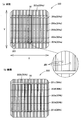
仕掛太陽電池パネル200は、図16(a)のように、一方の主面(表面)側に第1集電極204aとして、バスバー電極部201a,201bと、第1フィンガー電極部202aと、第2フィンガー電極部203a~203cを備えており、さらにパネル情報表示部205が設けられている。
仕掛太陽電池パネル200は、図16(a)のように、一方の主面(表面)側に第1集電極204aとして、バスバー電極部201a,201bと、第1フィンガー電極部202aと、第2フィンガー電極部203a~203cを備えており、さらにパネル情報表示部205が設けられている。
一方、仕掛太陽電池パネル200は、図16(b)のように、他方の主面(裏面)側に第2集電極204bとして、バスバー電極部201c,201dと、第1フィンガー電極部202bと、第2フィンガー電極部203d~203fを有している。
そして、仕掛太陽電池パネル200は、バスバー電極部201a,201b及びバスバー電極部201c,201dのそれぞれに配線部材(図示しない)を接続し、配線部材を介して外部負荷150に接続することで、仕掛品であるけれども太陽光等の光を受光したときに発電可能となっている。
そして、仕掛太陽電池パネル200は、バスバー電極部201a,201b及びバスバー電極部201c,201dのそれぞれに配線部材(図示しない)を接続し、配線部材を介して外部負荷150に接続することで、仕掛品であるけれども太陽光等の光を受光したときに発電可能となっている。
バスバー電極部201aは、切断加工後、バスバー電極部50となる部位であり、バスバー電極部201dは、バスバー電極部70となる部位である。
第1フィンガー電極部202aは、切断加工後、第1フィンガー電極部51a~51eとなる部位であり、第1フィンガー電極部202bは、第1フィンガー電極部71a~71eとなる部位である。
第1フィンガー電極部202aには、切断加工後、位置情報表示部58に対応する位置情報表示部207を備えている。
第2フィンガー電極部203a~203cは、切断加工後、第2フィンガー電極部52a~52cとなる部位であり、第2フィンガー電極部203d~203fは、切断後、第2フィンガー電極部72a~72cとなる部位である。
第2フィンガー電極部203a~203cは、切断加工後、第2フィンガー電極部52a~52cとなる部位であり、第2フィンガー電極部203d~203fは、切断後、第2フィンガー電極部72a~72cとなる部位である。
パネル情報表示部205は、仕掛太陽電池パネル200の管理情報が直接又は間接的に表示されるものである。本実施形態のパネル情報表示部205は、二次元コードであり、外部端末で読み取ることで外部機器に仕掛太陽電池パネル200の情報を表示可能となっている。
続いて、太陽電池モジュール1を管理する管理システム300について説明する。
管理システム300は、図17のように、制御装置301と読取装置302(読み取り手段)が無線又は有線によって接続されたものである。
本実施形態の管理システム300は、制御装置301と読取装置302がインターネットやイントラネット等のネットワーク303を介して相互に通信可能となっている。
本実施形態の管理システム300は、制御装置301と読取装置302がインターネットやイントラネット等のネットワーク303を介して相互に通信可能となっている。
制御装置301は、特定部310(特定手段)と、照合部311と、記憶部312と、入出力部313を備えている。制御装置301は、読取装置302から太陽電池セル30の情報を受信したときに、あらかじめ記憶部312に記憶された各列の太陽電池セル30の情報と受信した情報を照合部311が照合し、特定部310が各列の太陽電池セル30を特定可能となっている。
読取装置302は、図17のように、読取部305と、入出力部306を備えており、読取部305でインターコネクタ31bに設けられた情報表示部88a,88bを読み取ることで、インターコネクタ31aで接続される各列の太陽電池セル30の情報を制御装置301に送信可能となっている。
続いて、太陽電池モジュール1の製造方法について説明する。
まず、外部負荷150に接続することで光電変換可能な仕掛太陽電池パネル200を形成する仕掛太陽電池形成工程を行う。なお、仕掛太陽電池形成工程で形成される仕掛太陽電池パネル200の製造は、従来の太陽電池パネルとほぼ同様であり、公知であるため、本工程については簡単に説明する。
半導体基板の両面にCVD装置等を用いて半導体層を形成していき、光電変換部41を形成し、光電変換部41の両面にCVD装置等を用いて下地電極層45,65を形成する。そして、スクリーン印刷等によって各下地電極層45,65上に集電極204a,204bを形成し、仕掛太陽電池パネル200を形成する。
このとき、表側にはパネル情報表示部205及び位置情報表示部207が形成されている。
また、管理システム300の制御装置301は、各太陽電池セル30の位置情報表示部207と仕掛太陽電池パネル200での分割位置を紐付けて記憶部312で記憶し、位置情報表示部207から自己の太陽電池セル30と仕掛太陽電池パネル200での分割位置を照合可能とする。
このとき、必要に応じて、配線部材を介して仕掛太陽電池パネル200を外部負荷150に接続して発電特性を測定し、当該発電特性から仕掛太陽電池パネル200が不良品であるか確認してもよい。
また、管理システム300の制御装置301は、各太陽電池セル30の位置情報表示部207と仕掛太陽電池パネル200での分割位置を紐付けて記憶部312で記憶し、位置情報表示部207から自己の太陽電池セル30と仕掛太陽電池パネル200での分割位置を照合可能とする。
このとき、必要に応じて、配線部材を介して仕掛太陽電池パネル200を外部負荷150に接続して発電特性を測定し、当該発電特性から仕掛太陽電池パネル200が不良品であるか確認してもよい。
続いて、太陽電池ストリング12を形成する太陽電池ストリング工程を行う。
具体的には、図16の二点鎖線のように、第1フィンガー電極部202a,202bの長手方向の中間部が分割されるように仕掛太陽電池パネル200を切断し、複数の太陽電池セル30に分割し、太陽電池セル30を形成する(セル分割工程,太陽電池セル形成工程)。
具体的には、横方向Xにおいて等間隔に分割し、縦方向Yにおいて仕掛太陽電池パネル200の位置情報表示部207が含まれるようにバスバー電極部201bの内側部分と、バスバー電極部201aの外側をそれぞれ分割する。
分割方法としては、特に限定されるものではないが、本実施形態では、いわゆる折り割によって分割しており、第2電極層42側からレーザーを照射して光電変換部41の半導体基板まで切り目(溝)を入れ、当該切り目(溝)に沿って折り曲げることによって分割している。
具体的には、図16の二点鎖線のように、第1フィンガー電極部202a,202bの長手方向の中間部が分割されるように仕掛太陽電池パネル200を切断し、複数の太陽電池セル30に分割し、太陽電池セル30を形成する(セル分割工程,太陽電池セル形成工程)。
具体的には、横方向Xにおいて等間隔に分割し、縦方向Yにおいて仕掛太陽電池パネル200の位置情報表示部207が含まれるようにバスバー電極部201bの内側部分と、バスバー電極部201aの外側をそれぞれ分割する。
分割方法としては、特に限定されるものではないが、本実施形態では、いわゆる折り割によって分割しており、第2電極層42側からレーザーを照射して光電変換部41の半導体基板まで切り目(溝)を入れ、当該切り目(溝)に沿って折り曲げることによって分割している。
分割された太陽電池セル30においての長手方向の端部に流動性を有する絶縁保護材33を塗布し、図11のように、第1フィンガー電極部51a~51eの張出部56a,56b,57a,57bを絶縁保護材33で埋没させる(塗布工程)。
そして、一の太陽電池セル30のバスバー電極部50に導電性接着材32を介してインターコネクタ31a,31bの一端側を接続し(配線接続工程)、さらに他の太陽電池セル30のバスバー電極部70にインターコネクタ31a,31bの他端側を接続する(第2配線接続工程)。
なお、配線接続工程は、第2配線接続工程と同時に行ってもよいし、第2配線接続工程よりも前に行ってもよい。
なお、配線接続工程は、第2配線接続工程と同時に行ってもよいし、第2配線接続工程よりも前に行ってもよい。
直線インターコネクタ31aの一の太陽電池セル30と他の太陽電池セル30の間の部分に流動性をもつ着色材を塗布し、直線インターコネクタ31aの色よりも太陽電池セル30の色に近い色の着色層34を形成する(着色工程)。
このとき、着色材は、直線インターコネクタ31aの露出部分に塗布し、さらに、直線インターコネクタ31a上から太陽電池セル30上まで塗布し、硬化させる。
このとき、着色材は、直線インターコネクタ31aの露出部分に塗布し、さらに、直線インターコネクタ31a上から太陽電池セル30上まで塗布し、硬化させる。
また別途工程において、図12(b)のように折り返しインターコネクタ31bのコネクター部85,86に情報表示部88a,88bを形成する。そして、各太陽電池セル30の位置情報表示部58から仕掛太陽電池パネル200での分割位置を照合し、情報表示部88a,88bと各太陽電池セル30の位置と仕掛太陽電池パネル200での分割位置を紐付けする(情報表示部形成工程)。
各太陽電池ストリング12に取出配線14,15を接続して各太陽電池ストリング12を端子ボックス3a,3bに電気的に接続し、2枚の透光性基板10,11によって挟んで封止材16a,16bによって封止する。
続いて、第1実施形態の太陽電池モジュール1の修復方法について説明する。なお、以下の説明においては、発電側太陽電池ストリング37aが故障等により異常が生じたと仮定して説明する。
まず、図18のように、故障した発電側太陽電池ストリング37aに接続された分岐配線部91bを切断する。
具体的には、図19(a)のように分岐配線部91bと重なる蓋部材21bを取り外し、図19(b)のように貫通孔22bから専用の治具を挿入し分岐配線部91bを切断し、貫通孔22b内で断絶させる。
具体的には、図19(a)のように分岐配線部91bと重なる蓋部材21bを取り外し、図19(b)のように貫通孔22bから専用の治具を挿入し分岐配線部91bを切断し、貫通孔22b内で断絶させる。
続いて、図19(c)のように貫通孔22bに蓋部材21bを再度取り付け、貫通孔22bを塞ぐ。すなわち、分岐配線部91bの切断部分を覆うように蓋部材21bを被せる。
別途工程にて、図20(a)のように、予備太陽電池ストリング38に接続された分岐配線部91aと重なる蓋部材21aを取り外し、図20(b),図20(c)のように,貫通孔22aに接続用蓋部材110を取り付け、貫通孔22aを塞ぐ。
このとき、接続用蓋部材110には、太陽電池セル30側の部分に導電箔111(接続部材)が設けられており、導電箔111によって分岐配線部91aの断線部92を接続する。すなわち、図18(b)のように接続用蓋部材110の導電箔111によって、分岐配線部91aの太陽電池セル30側の部分と本体配線部90側の部分を電気的に接続する。
接続用蓋部材110の導電箔111は、導電性を有するものであれば、特に限定されるものではない。導電箔111は、例えば、金、銀、銅、白金、パラジウム等の金属や金属合金を使用できる。
このとき、接続用蓋部材110には、太陽電池セル30側の部分に導電箔111(接続部材)が設けられており、導電箔111によって分岐配線部91aの断線部92を接続する。すなわち、図18(b)のように接続用蓋部材110の導電箔111によって、分岐配線部91aの太陽電池セル30側の部分と本体配線部90側の部分を電気的に接続する。
接続用蓋部材110の導電箔111は、導電性を有するものであれば、特に限定されるものではない。導電箔111は、例えば、金、銀、銅、白金、パラジウム等の金属や金属合金を使用できる。
第1実施形態の太陽電池モジュール1によれば、図18(a)のように封止材16a,16bの外部で各発電側太陽電池ストリング37aを外部負荷150に対して電気的に開放し、予備太陽電池ストリング38を外部負荷150に対して電気的に接続可能である。そのため、一の発電側太陽電池ストリング37aが故障等により、発電しなかったとしても、図18(b)のように発電側太陽電池ストリング37aを外部負荷150に対して電気的に開放し、予備太陽電池ストリング38を外部負荷150に接続することで、設計通りの発電容量で発電できる。
第1実施形態の太陽電池モジュール1によれば、各発電側太陽電池ストリング37a~37eの分岐配線部91b~91fが発電側貫通孔22b~22fの開口から露出しており、予備太陽電池ストリング38は、分岐配線部91aの一部に断線部92があり、断線部92が予備側貫通孔22aの開口から露出している。そのため、一の分岐配線部91bの一部を切断し、分岐配線部91aの断線部92を電気的に接続することで、容易に発電に使用する太陽電池ストリング12を発電側太陽電池ストリング37aから予備太陽電池ストリング38に変更できる。
第1実施形態の太陽電池モジュール1によれば、第1フィンガー電極部51a~51eの末端電極部54,55の端部をなす張出部56a,56b,57a,57bが埋没するように太陽電池セル30の端面を絶縁保護材33が形成されている。そのため、第1フィンガー電極部51a~51eの末端電極部54,55の端部をなす張出部56a,56b,57a,57bがインターコネクタ31a,31bに直接接触することを防止できる。
第1実施形態の太陽電池モジュール1によれば、インターコネクタ31aの一部がインターコネクタ31aよりも太陽電池セル30の色に近い着色層34で覆われている。そのため、インターコネクタ31aの色を太陽電池セル30に近づけることができ、インターコネクタ31aの色が目立ちにくい。
第1実施形態の太陽電池モジュール1によれば、着色層34がインターコネクタ31a上から太陽電池セル30上に跨って設けられている。そのため、着色層34がインターコネクタ31aと太陽電池セル30の接着材としても機能し、インターコネクタ31aが太陽電池セル30から剥がれにくい。
第1実施形態の太陽電池モジュール1によれば、特定の太陽電池セル30bに初期不良等の不具合が生じた場合であっても、情報表示部88a,88bに太陽電池セル情報に関連付けられた関連情報が表示されるので、不具合の生じた特定の太陽電池セル30bと、仕掛太陽電池パネル200の関係が特定可能である。そのため、不具合の原因の特定等のフィードバックが容易である。
第1実施形態の太陽電池モジュール1によれば、情報表示部88a,88bが太陽電池セル30を基準として厚み方向の外側から第1透光性基板10及び封止材16aを透過して視認可能である。そのため、情報表示部88a,88bの位置を確認しやすく、情報表示部88a,88bを第1透光性基板10の外側から読取部305で読み取り可能である。
第1実施形態の太陽電池モジュール1によれば、情報表示部88a,88bとは別に、各太陽電池セル30に分割前の仕掛太陽電池パネル200における位置情報を表示する位置情報表示部58を備えている。そのため、太陽電池セル30からインターコネクタ31a,31bを外した後でも太陽電池セル30の位置情報を特定できる。
第1実施形態の太陽電池モジュール1によれば、位置情報表示部58が直線インターコネクタ31aから外れた位置に形成されている。そのため、直線インターコネクタ31aが接続された状態でも、位置情報表示部58が視認可能であり、太陽電池セル30の分割前の仕掛太陽電池パネル200における位置情報を特定できる。
第1実施形態の修復方法で修復した修復済み太陽電池モジュール1によれば、外観上、修復前と実質的に同様の見た目の太陽電池モジュールとなる。
第1実施形態の管理システム300によれば、読取部305によって太陽電池モジュール1の情報表示部88a,88bから太陽電池セル情報に関連情報を読み取って、特定部310によって関連情報から太陽電池セル情報を特定可能である。そのため、製造時において多数の太陽電池モジュール1を一括で管理できる。また、特定の太陽電池セル30bに初期不良等の不具合が生じた場合であっても、特定の太陽電池セル30bと、仕掛太陽電池パネル200の関係が特定可能である。そのため、不具合の原因の特定等のフィードバックが容易である。
続いて、本発明の第2実施形態の太陽電池モジュールについて説明する。なお、第1実施形態の太陽電池モジュール1と同様の構成については、同一の符号を付して説明を省略する。
第2実施形態の太陽電池モジュールは、太陽電池ストリングの構造が第1実施形態と異なる。
第2実施形態の太陽電池ストリング612は、図21のように、主要構成部材として、複数の太陽電池セル30と、インターコネクタ31a,31bと、導電性接着材32と、着色保護層633とで構成されている。
着色保護層633は、絶縁性を有し、インターコネクタ31aとは異なる色に着色された層である。着色保護層633は、太陽電池セル30の色と同系色であって、インターコネクタ31aの色よりも太陽電池セル30の色に近い色に着色されている。
すなわち、着色保護層633は、第1実施形態の絶縁保護材33としての機能と着色層34としての機能を兼ね備えたものである。
着色保護層633は、図21のように、インターコネクタ31aの表側及び裏側で、一方の太陽電池セル30eの端面、インターコネクタ31a上、他方の太陽電池セル30fの端面に跨って設けられている。
第2実施形態の太陽電池ストリング612は、図21のように、主要構成部材として、複数の太陽電池セル30と、インターコネクタ31a,31bと、導電性接着材32と、着色保護層633とで構成されている。
着色保護層633は、絶縁性を有し、インターコネクタ31aとは異なる色に着色された層である。着色保護層633は、太陽電池セル30の色と同系色であって、インターコネクタ31aの色よりも太陽電池セル30の色に近い色に着色されている。
すなわち、着色保護層633は、第1実施形態の絶縁保護材33としての機能と着色層34としての機能を兼ね備えたものである。
着色保護層633は、図21のように、インターコネクタ31aの表側及び裏側で、一方の太陽電池セル30eの端面、インターコネクタ31a上、他方の太陽電池セル30fの端面に跨って設けられている。
続いて、第2実施形態の太陽電池モジュールの製造方法について説明する。なお、太陽電池ストリング工程以外は、第1実施形態と同様であるため、太陽電池ストリング工程のみ説明する。
本実施形態の太陽電池ストリング工程では、まず、第1フィンガー電極部202a,202bの長手方向の中間部が分割されるように仕掛太陽電池パネル200を切断し、複数の太陽電池セル30に分割する(セル分割工程)。
続いて、一の太陽電池セル30fのバスバー電極部50に導電性接着材32を介してインターコネクタ31a,31bの一端側を接続し(配線接続工程)、さらに他の太陽電池セル30eのバスバー電極部70にインターコネクタ31a,31bの他端側を接続する(第2配線接続工程)。
そして、一の太陽電池セル30の端面からインターコネクタ31a、他の太陽電池セル30上に亘って流動性を有する着色保護材(絶縁保護材)を塗布し着色保護層633を形成するとともに、図21のように、第1フィンガー電極部51a~51eの張出部56a,56b,57a,57bを着色保護層633で埋没させる(塗布工程)。
すなわち、着色保護材は、直線インターコネクタ31aの露出部分に塗布し、さらに、一の太陽電池セル30の端面から他の太陽電池セル30上まで塗布し、硬化させる。
すなわち、着色保護材は、直線インターコネクタ31aの露出部分に塗布し、さらに、一の太陽電池セル30の端面から他の太陽電池セル30上まで塗布し、硬化させる。
第2実施形態の太陽電池モジュールによれば、着色保護層633に絶縁保護材33としての機能と着色層34としての機能を持たせているため、コストを低減できる。
第2実施形態の太陽電池モジュールの製造方法によれば、塗布工程を配線接続工程よりも後に行い、インターコネクタ31a及び太陽電池セル30の端面に跨って絶縁保護材を兼ねる着色保護材を塗布する。そのため、製造工程を簡略化できる。
上記した第1実施形態では、修復する際に異常が生じた太陽電池ストリング12に接続された取出配線14の一部を切断して異常が生じた太陽電池ストリング12を他の太陽電池ストリング12から電気的に切り離したが、本発明はこれに限定されるものではない。異常が生じた太陽電池ストリング12を構成するインターコネクタ31a,31bを切断して異常が生じた太陽電池ストリング12を他の太陽電池ストリング12から電気的に切り離してもよい。
上記した実施形態では、縦方向Yに太陽電池セル30が並んでいたが、本発明はこれに限定されるものではない。太陽電池セル30は、横方向Xに並んでいてもよいし、斜め方向に並んでいてもよい。
上記した第1実施形態では、予備太陽電池ストリング38の正極側端部35に接続される取出配線14に断線部92を設けていたが、本発明はこれに限定されるものではない。予備太陽電池ストリング38の負極側端部36に接続される取出配線15に断線部92を設けてもよい。
上記した実施形態では、太陽電池セル30は、縦長長方形状をしていたが、本発明はこれに限定されるものではなく、太陽電池セル30の形状は特に限定されない。
太陽電池セル30は、従来と同様、略正方形状であってもよいし、三角形、四角形、五角形、六角形等の多角形状であってもよい。また、円形状や楕円状であってもよい。
太陽電池セル30は、従来と同様、略正方形状であってもよいし、三角形、四角形、五角形、六角形等の多角形状であってもよい。また、円形状や楕円状であってもよい。
上記した実施形態では、導電性接着材32は、バスバー電極部50,70上のみに接着されていたが、本発明はこれに限定されるものではない。導電性接着材32は、バスバー電極部50,70上から外側端部に向けて第1フィンガー電極部51,71上や下地電極層45,65上に跨って設けられていてもよい。
上記した実施形態では、接続用蓋部材110は、導電箔111によって断線部92を電気的に接続していたが、本発明はこれに限定されるものではなく、断線部92を電気的に接続する接続部材の形状は特に問わない。接続部材は、板状であってもよいし、線状であってもよい。
上記した実施形態は、本発明の技術的範囲に含まれる限り、各実施形態間で各構成部材を自由に置換や付加できる。
1 太陽電池モジュール
12,612 太陽電池ストリング(直列接続群)
30,30a~30f 太陽電池セル
31a 直線インターコネクタ(導電体)
32 導電性接着材
33 絶縁保護材
34 着色層
50 バスバー電極部
51a~51e 第1フィンガー電極部
52a~52e 第2フィンガー電極部
54,55 末端電極部
56a,56b,57a,57b 張出部
70 バスバー電極部
71a~71e 第1フィンガー電極部
72a~72e 第2フィンガー電極部
74,75 末端電極部
150 外部負荷
200 仕掛太陽電池パネル
201a~201d バスバー電極部
202a,202b 第1フィンガー電極部
203a~203c 第2フィンガー電極部
633 着色保護層
12,612 太陽電池ストリング(直列接続群)
30,30a~30f 太陽電池セル
31a 直線インターコネクタ(導電体)
32 導電性接着材
33 絶縁保護材
34 着色層
50 バスバー電極部
51a~51e 第1フィンガー電極部
52a~52e 第2フィンガー電極部
54,55 末端電極部
56a,56b,57a,57b 張出部
70 バスバー電極部
71a~71e 第1フィンガー電極部
72a~72e 第2フィンガー電極部
74,75 末端電極部
150 外部負荷
200 仕掛太陽電池パネル
201a~201d バスバー電極部
202a,202b 第1フィンガー電極部
203a~203c 第2フィンガー電極部
633 着色保護層
Claims (11)
- 太陽電池セルと、前記太陽電池セルと他の太陽電池セルを接続する配線部材を有し、
前記太陽電池セルは、幅をもって所定の方向に延びるものであり、
前記太陽電池セルは、幅方向に延びるバスバー電極部と、前記バスバー電極部から長手方向に延びる複数のフィンガー電極部を有し、
前記フィンガー電極部は、前記バスバー電極部から前記太陽電池セルの長手方向の端部まで至る末端電極部を有し、
前記配線部材は、前記バスバー電極部に対して導電性接着材を介して接続され、平面視したときに前記末端電極部と重なるように延びており、
前記末端電極部の端部が埋没するように前記太陽電池セルの端面を覆う絶縁保護材を備えている、太陽電池モジュール。 - 前記末端電極部は、一部が前記太陽電池セルの長手方向の端部から張り出しており、
前記末端電極部の張出部分が前記絶縁保護材に埋没している、請求項1に記載の太陽電池モジュール。 - 前記配線部材とは異なる色の着色層を有し、
前記着色層は、前記配線部材の一部を覆うものであり、
前記配線部材は、一部が前記着色層で被覆され、平面視したときに、接続する前記太陽電池セルと前記他の太陽電池セルとの間の部分が前記着色層によって前記配線部材の色よりも前記太陽電池セルの色に近い色に着色されている、請求項1又は2に記載の太陽電池モジュール。 - 前記着色層は、前記配線部材と前記太陽電池セルに跨って設けられている、請求項3に記載の太陽電池モジュール。
- 前記配線部材は、前記着色層から露出した露出部を有し、
前記露出部は、前記バスバー電極部に対して導電性接着材を介して接続されている、請求項3又は4に記載の太陽電池モジュール。 - 前記着色層は、前記絶縁保護材によって構成されている、請求項3乃至5のいずれか1項に記載の太陽電池モジュール。
- 前記配線部材は、平面視したときに、前記複数のフィンガー電極部の末端電極部と重なっている、請求項1乃至6のいずれか1項に記載の太陽電池モジュール。
- 幅方向に並設された複数のフィンガー電極部と、幅方向に延び前記複数のフィンガー電極部を接続するバスバー電極部をもち、外部負荷に接続することで光電変換可能な仕掛太陽電池パネルを使用する太陽電池モジュールの製造方法であって、
前記フィンガー電極部の長手方向の中間部が分割されるように前記仕掛太陽電池パネルを切断し、複数の太陽電池セルに分割するセル分割工程と、
分割された一の太陽電池セルにおいて前記フィンガー電極部の長手方向の端部が埋没するように前記太陽電池セルの端面に絶縁保護材を塗布する塗布工程と、
前記一の太陽電池セルの前記バスバー電極部に対して導電性接着材を介して配線部材の一端側を接続する配線接続工程を含む、太陽電池モジュールの製造方法。 - 前記セル分割工程では、折り割によって前記仕掛太陽電池パネルを前記複数の太陽電池セルに分割する、請求項8に記載の太陽電池モジュールの製造方法。
- 他の太陽電池セルに前記配線部材の他端側を接続する第2配線接続工程と、
前記配線部材の前記一の太陽電池セルと前記他の太陽電池セルの間の部分に前記配線部材の色よりも前記太陽電池セルの色に近い色の着色材を塗布する着色工程を含む、請求項8又は9に記載の太陽電池モジュールの製造方法。 - 前記絶縁保護材は、前記配線部材の色よりも前記太陽電池セルの色に近い色に着色されており、
前記塗布工程は、前記配線接続工程よりも後に行うものであり、
前記塗布工程において、前記配線部材及び前記太陽電池セルの端面に跨って前記絶縁保護材を塗布する、請求項8又は9に記載の太陽電池モジュールの製造方法。
Priority Applications (1)
| Application Number | Priority Date | Filing Date | Title |
|---|---|---|---|
| JP2021507155A JP7471273B2 (ja) | 2019-03-20 | 2020-03-02 | 太陽電池モジュール及び太陽電池モジュールの製造方法 |
Applications Claiming Priority (2)
| Application Number | Priority Date | Filing Date | Title |
|---|---|---|---|
| JP2019052833 | 2019-03-20 | ||
| JP2019-052833 | 2019-03-20 |
Publications (1)
| Publication Number | Publication Date |
|---|---|
| WO2020189240A1 true WO2020189240A1 (ja) | 2020-09-24 |
Family
ID=72520909
Family Applications (1)
| Application Number | Title | Priority Date | Filing Date |
|---|---|---|---|
| PCT/JP2020/008715 Ceased WO2020189240A1 (ja) | 2019-03-20 | 2020-03-02 | 太陽電池モジュール及び太陽電池モジュールの製造方法 |
Country Status (2)
| Country | Link |
|---|---|
| JP (1) | JP7471273B2 (ja) |
| WO (1) | WO2020189240A1 (ja) |
Cited By (1)
| Publication number | Priority date | Publication date | Assignee | Title |
|---|---|---|---|---|
| JP7049514B1 (ja) | 2021-08-27 | 2022-04-06 | 上海晶科緑能企業管理有限公司 | セル及び太陽電池モジュール |
Citations (7)
| Publication number | Priority date | Publication date | Assignee | Title |
|---|---|---|---|---|
| WO2013140552A1 (ja) * | 2012-03-21 | 2013-09-26 | 三洋電機株式会社 | 太陽電池モジュール |
| JP2014175520A (ja) * | 2013-03-11 | 2014-09-22 | Mitsubishi Electric Corp | 太陽電池モジュ−ル及びその製造方法 |
| WO2015152020A1 (ja) * | 2014-03-31 | 2015-10-08 | 株式会社カネカ | 太陽電池モジュールおよびその製造方法 |
| US20160225931A1 (en) * | 2015-02-02 | 2016-08-04 | Silevo, Inc. | Bifacial photovoltaic module using heterojunction solar cells |
| JP2017502525A (ja) * | 2014-01-13 | 2017-01-19 | ソーラーシティ コーポレーション | 低抵抗率電極を備えた太陽電池のモジュール製作 |
| WO2018084159A1 (ja) * | 2016-11-02 | 2018-05-11 | 株式会社カネカ | 太陽電池およびその製造方法、ならびに太陽電池モジュール |
| WO2018116899A1 (ja) * | 2016-12-22 | 2018-06-28 | パナソニックIpマネジメント株式会社 | 太陽電池モジュール |
Family Cites Families (3)
| Publication number | Priority date | Publication date | Assignee | Title |
|---|---|---|---|---|
| JP2004342768A (ja) * | 2003-05-14 | 2004-12-02 | Matsushita Electric Ind Co Ltd | 薄膜太陽電池モジュール |
| US10964826B2 (en) * | 2013-10-30 | 2021-03-30 | Kaneka Corporation | Solar cell and production method therefor, and solar cell module |
| WO2018209240A1 (en) * | 2017-05-12 | 2018-11-15 | Flex Ltd | Shingled array module for vehicle solar roof |
-
2020
- 2020-03-02 JP JP2021507155A patent/JP7471273B2/ja active Active
- 2020-03-02 WO PCT/JP2020/008715 patent/WO2020189240A1/ja not_active Ceased
Patent Citations (7)
| Publication number | Priority date | Publication date | Assignee | Title |
|---|---|---|---|---|
| WO2013140552A1 (ja) * | 2012-03-21 | 2013-09-26 | 三洋電機株式会社 | 太陽電池モジュール |
| JP2014175520A (ja) * | 2013-03-11 | 2014-09-22 | Mitsubishi Electric Corp | 太陽電池モジュ−ル及びその製造方法 |
| JP2017502525A (ja) * | 2014-01-13 | 2017-01-19 | ソーラーシティ コーポレーション | 低抵抗率電極を備えた太陽電池のモジュール製作 |
| WO2015152020A1 (ja) * | 2014-03-31 | 2015-10-08 | 株式会社カネカ | 太陽電池モジュールおよびその製造方法 |
| US20160225931A1 (en) * | 2015-02-02 | 2016-08-04 | Silevo, Inc. | Bifacial photovoltaic module using heterojunction solar cells |
| WO2018084159A1 (ja) * | 2016-11-02 | 2018-05-11 | 株式会社カネカ | 太陽電池およびその製造方法、ならびに太陽電池モジュール |
| WO2018116899A1 (ja) * | 2016-12-22 | 2018-06-28 | パナソニックIpマネジメント株式会社 | 太陽電池モジュール |
Cited By (3)
| Publication number | Priority date | Publication date | Assignee | Title |
|---|---|---|---|---|
| JP7049514B1 (ja) | 2021-08-27 | 2022-04-06 | 上海晶科緑能企業管理有限公司 | セル及び太陽電池モジュール |
| JP2023033040A (ja) * | 2021-08-27 | 2023-03-09 | 上海晶科緑能企業管理有限公司 | セル及び太陽電池モジュール |
| US11973150B2 (en) | 2021-08-27 | 2024-04-30 | Shanghai Jinko Green Energy Enterprise Management Co., Ltd. | Solar cell and solar cell module |
Also Published As
| Publication number | Publication date |
|---|---|
| JPWO2020189240A1 (ja) | 2020-09-24 |
| JP7471273B2 (ja) | 2024-04-19 |
Similar Documents
| Publication | Publication Date | Title |
|---|---|---|
| CN108512508B (zh) | 太阳能电池模块 | |
| WO2015133632A1 (ja) | 太陽電池モジュール、太陽電池モジュール用封止材、それらの製造方法 | |
| KR20070098723A (ko) | 태양 전지 모듈 | |
| KR102243603B1 (ko) | 태양전지 모듈 및 그 제조 방법 | |
| EP3432365B1 (en) | Solar module and method for fabricating the same | |
| WO2013183395A1 (ja) | 太陽電池モジュール及び太陽電池モジュールの製造方法 | |
| TW201324823A (zh) | 用於標準結晶矽太陽能電池的單片式模組組件 | |
| CN110335912B (zh) | 光伏导电玻璃、太阳能电池双玻组件及其制备方法 | |
| CN109801981B (zh) | 太阳能电池片用l形连接件及其应用 | |
| JP2008300449A (ja) | 太陽電池モジュール及びその製造方法 | |
| US20190319147A1 (en) | Bifacial photovoltaic module | |
| NL2006852C2 (en) | Solar panel module and method for manufacturing such a solar panel module. | |
| CN112086520B (zh) | 太阳能电池组件及制备方法 | |
| WO2008148524A2 (en) | Solar module with an electrical connector element | |
| WO2020189240A1 (ja) | 太陽電池モジュール及び太陽電池モジュールの製造方法 | |
| JP2005191125A (ja) | 太陽電池素子接続用接続タブ及び太陽電池モジュール並びに太陽電池モジュールの製造方法 | |
| CN102347713B (zh) | 母线带与箔片条带接触改善的光伏(pv)模块 | |
| WO2020100528A1 (ja) | 太陽電池モジュール及びその製造方法 | |
| JP7325199B2 (ja) | 太陽電池モジュール、修復済み太陽電池モジュール、及び太陽電池モジュールの修復方法 | |
| JP7359557B2 (ja) | 太陽電池モジュール及び太陽電池モジュールの管理システム | |
| CN110085692B (zh) | 光伏导电背板、太阳能电池组件及其制备方法 | |
| JP2013143401A (ja) | 太陽電池モジュール、およびその製造方法 | |
| EP4307393A1 (en) | Method for manufacturing a solar cell module and solar cell module | |
| EP3200239B1 (en) | Solar cell module and method for manufacturing solar cell module | |
| JP4883891B2 (ja) | 太陽電池モジュール |
Legal Events
| Date | Code | Title | Description |
|---|---|---|---|
| 121 | Ep: the epo has been informed by wipo that ep was designated in this application |
Ref document number: 20773218 Country of ref document: EP Kind code of ref document: A1 |
|
| ENP | Entry into the national phase |
Ref document number: 2021507155 Country of ref document: JP Kind code of ref document: A |
|
| NENP | Non-entry into the national phase |
Ref country code: DE |
|
| 122 | Ep: pct application non-entry in european phase |
Ref document number: 20773218 Country of ref document: EP Kind code of ref document: A1 |