WO2020189170A1 - 不織布製造方法 - Google Patents
不織布製造方法 Download PDFInfo
- Publication number
- WO2020189170A1 WO2020189170A1 PCT/JP2020/006826 JP2020006826W WO2020189170A1 WO 2020189170 A1 WO2020189170 A1 WO 2020189170A1 JP 2020006826 W JP2020006826 W JP 2020006826W WO 2020189170 A1 WO2020189170 A1 WO 2020189170A1
- Authority
- WO
- WIPO (PCT)
- Prior art keywords
- woven fabric
- collector
- nonwoven fabric
- fiber
- solvent
- Prior art date
- Legal status (The legal status is an assumption and is not a legal conclusion. Google has not performed a legal analysis and makes no representation as to the accuracy of the status listed.)
- Ceased
Links
Images

Classifications
-
- D—TEXTILES; PAPER
- D04—BRAIDING; LACE-MAKING; KNITTING; TRIMMINGS; NON-WOVEN FABRICS
- D04H—MAKING TEXTILE FABRICS, e.g. FROM FIBRES OR FILAMENTARY MATERIAL; FABRICS MADE BY SUCH PROCESSES OR APPARATUS, e.g. FELTS, NON-WOVEN FABRICS; COTTON-WOOL; WADDING ; NON-WOVEN FABRICS FROM STAPLE FIBRES, FILAMENTS OR YARNS, BONDED WITH AT LEAST ONE WEB-LIKE MATERIAL DURING THEIR CONSOLIDATION
- D04H1/00—Non-woven fabrics formed wholly or mainly of staple fibres or like relatively short fibres
- D04H1/70—Non-woven fabrics formed wholly or mainly of staple fibres or like relatively short fibres characterised by the method of forming fleeces or layers, e.g. reorientation of fibres
- D04H1/72—Non-woven fabrics formed wholly or mainly of staple fibres or like relatively short fibres characterised by the method of forming fleeces or layers, e.g. reorientation of fibres the fibres being randomly arranged
- D04H1/728—Non-woven fabrics formed wholly or mainly of staple fibres or like relatively short fibres characterised by the method of forming fleeces or layers, e.g. reorientation of fibres the fibres being randomly arranged by electro-spinning
-
- D—TEXTILES; PAPER
- D01—NATURAL OR MAN-MADE THREADS OR FIBRES; SPINNING
- D01D—MECHANICAL METHODS OR APPARATUS IN THE MANUFACTURE OF ARTIFICIAL FILAMENTS, THREADS, FIBRES, BRISTLES OR RIBBONS
- D01D5/00—Formation of filaments, threads, or the like
- D01D5/0007—Electro-spinning
- D01D5/0015—Electro-spinning characterised by the initial state of the material
- D01D5/003—Electro-spinning characterised by the initial state of the material the material being a polymer solution or dispersion
-
- D—TEXTILES; PAPER
- D01—NATURAL OR MAN-MADE THREADS OR FIBRES; SPINNING
- D01D—MECHANICAL METHODS OR APPARATUS IN THE MANUFACTURE OF ARTIFICIAL FILAMENTS, THREADS, FIBRES, BRISTLES OR RIBBONS
- D01D5/00—Formation of filaments, threads, or the like
- D01D5/04—Dry spinning methods
-
- D—TEXTILES; PAPER
- D01—NATURAL OR MAN-MADE THREADS OR FIBRES; SPINNING
- D01F—CHEMICAL FEATURES IN THE MANUFACTURE OF ARTIFICIAL FILAMENTS, THREADS, FIBRES, BRISTLES OR RIBBONS; APPARATUS SPECIALLY ADAPTED FOR THE MANUFACTURE OF CARBON FILAMENTS
- D01F2/00—Monocomponent artificial filaments or the like of cellulose or cellulose derivatives; Manufacture thereof
-
- D—TEXTILES; PAPER
- D04—BRAIDING; LACE-MAKING; KNITTING; TRIMMINGS; NON-WOVEN FABRICS
- D04H—MAKING TEXTILE FABRICS, e.g. FROM FIBRES OR FILAMENTARY MATERIAL; FABRICS MADE BY SUCH PROCESSES OR APPARATUS, e.g. FELTS, NON-WOVEN FABRICS; COTTON-WOOL; WADDING ; NON-WOVEN FABRICS FROM STAPLE FIBRES, FILAMENTS OR YARNS, BONDED WITH AT LEAST ONE WEB-LIKE MATERIAL DURING THEIR CONSOLIDATION
- D04H1/00—Non-woven fabrics formed wholly or mainly of staple fibres or like relatively short fibres
- D04H1/40—Non-woven fabrics formed wholly or mainly of staple fibres or like relatively short fibres from fleeces or layers composed of fibres without existing or potential cohesive properties
- D04H1/42—Non-woven fabrics formed wholly or mainly of staple fibres or like relatively short fibres from fleeces or layers composed of fibres without existing or potential cohesive properties characterised by the use of certain kinds of fibres insofar as this use has no preponderant influence on the consolidation of the fleece
- D04H1/425—Cellulose series
Definitions
- the present invention relates to a non-woven fabric manufacturing method.
- Nonwoven fabrics formed from fibers are known. Nonwoven fabrics are being actively developed for use in various fields. Expected applications include, for example, heat insulating materials, sound absorbing materials, filters, etc., and are also expected to be used for medical purposes and as scaffolding materials for cells.
- the non-woven fabric is manufactured by, for example, an electric field spinning method.
- the electrospinning method which is also called an electrospinning method, applies a voltage between a fiber material (a solution in which the fiber material is dissolved in a solvent) and a collector, and makes one positive (+) and the other negative (-).
- a non-woven fabric is formed by charging and ejecting a fiber material toward a collector to form a fiber, and collecting the formed fiber with a collector.
- Patent Documents 1 and 2 describe a configuration in which charged air is blown to remove static electricity from the non-woven fabric. By doing so, the thickness can be reduced and the hole diameter can be kept small. That is, since the fibers constituting the non-woven fabric are charged with the same polarity as the non-woven fabric, a repulsive force (repulsive force) is generated between the fibers, but the repulsive force is suppressed (reduced) by static elimination to reduce the thickness and pore diameter. Can be kept small.
- the present invention has been made in view of the above background, and an object of the present invention is to provide a non-woven fabric manufacturing method capable of manufacturing a non-woven fabric in which the pore diameter changes from one end surface to the other end surface without a boundary.
- the non-woven fabric manufacturing method of the present invention applies a voltage between a solution in which a fiber material is dissolved in a solvent and a collector, and ejects the solution toward the collector to form a fiber.
- the non-woven fabric manufacturing method in which the non-woven fabric is collected as a non-woven fabric by a collector, 0.03 ⁇ / W ⁇ 0 when the texture of the non-woven fabric is W (g / m 2 ) and the absolute value of the charge amount is ⁇ (kV). .15 is satisfied.
- the solvent is preferably a mixture of a plurality of compounds.
- the boiling point of the solvent is preferably 80 ° C. or lower.
- the solvent preferably contains dichloromethane and methanol.
- the fiber material is a cellulosic polymer.
- the cellulosic polymer is preferably cellulose acylate.
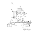
- the non-woven fabric manufacturing facility 10 of the present invention is for forming a fiber 11 and manufacturing a non-woven fabric 20 by using an electric field spinning method, and is a solution preparing unit 23 and a non-woven fabric manufacturing unit. 24 and.
- the solution preparation unit 23 is for preparing the solution 23a forming the fiber 11.
- the solution preparation unit 23 prepares the solution 23a by dissolving the material (fiber material) of the fiber 11 in a solvent.
- a resin can be used as the fiber material.
- the polymer it is preferable to use a polymer that can be made into a solution by dissolving it in a solvent, and more preferably a polymer that can be made into a solution by being dissolved in an organic solvent.
- PVA polylactic acid
- PMMA polymethylmethacrylate
- PAN polyacrylic nitrile
- PVA polyvinyl alcohol
- cellulose-based polymer polyester, polyurethane, elastoma and the like can be mentioned.
- the cellulosic polymer is preferably cellulose acylate.
- Cellulose acylate is a cellulose ester in which some or all of the hydrogen atoms constituting the hydroxy group of cellulose are substituted with an acyl group.
- the cellulose acylate is preferably one of cellulose acetate propionate (CAP), cellulose triacetate (TAC) and cellulose diacetate (DAC).
- the solvent may be composed of one kind of compound or may be composed of two or more kinds of compounds.
- the solvent since the solvent has a function of adjusting the evaporation rate in addition to the viewpoint of dissolving the fiber material, it is preferable that the solvent is a mixture composed of two or more kinds of compounds from the viewpoint of adjusting the evaporation rate.
- Specific examples thereof include a mixture of dichloromethane (DCM) and methanol (Methanol), chloroform (CHCl 3 ), water, dimethylformamide (DMF) and the like.
- ethanol isopropanol, butanol, benzyl alcohol, methyl ethyl ketone, cyclohexanone, methyl acetate, ethyl acetate, propyl acetate, butyl acetate, methyl formate, ethyl formate, hexane, cyclohexane, carbon tetrachloride, benzene, xylene, N.
- -Methylpyrrolidone diethyl ether, dioxane, 1-methoxy-2-propanol, toluene, acetone, tetrahydrofuran and the like can be used. These may be used alone or in combination of two or more.
- the solvent preferably has a boiling point of 80 ° C. or lower.
- the boiling point of the compound having the largest mass ratio is regarded as the boiling point of the solvent.
- the solvent is a mixture of three or more kinds of compounds and there are a plurality of compounds having the highest mass ratio
- the boiling point of the compound having the highest boiling point is regarded as the boiling point of the solvent.
- the solvent is a mixture of compound a, compound b, and compound c
- the boiling point of one of compound a and compound b, which has a higher boiling point is regarded as the boiling point of the solvent.
- the solvent is preferably an organic compound, that is, an organic solvent.
- the non-woven fabric manufacturing unit 24 includes a nozzle unit 25, an integrated unit 26, a power supply 27, a static eliminator 28, and a charge meter 29.
- the nozzle unit 25 is formed long in the width direction of the support 30 described later (see FIG. 1). Further, in the present embodiment, as described above, the nozzle units 25 long in the width direction of the support 30 are arranged side by side in the longitudinal direction of the support 30, and in the present embodiment, the three nozzle units 25 are arranged. (Three rows of nozzle units 25 are provided) (see FIG. 2). In these nozzle units 25, a plurality of nozzles 25a (three in the present embodiment) are arranged side by side along the longitudinal direction of the nozzle unit 25 (that is, the width direction of the support 30) (see FIG.
- the solution 23a prepared by the solution preparation unit 23 is supplied to each nozzle 25a, and the solution 23a is discharged from each nozzle 25a toward the integration unit 26.
- the number of nozzle units 25 and the number of nozzles 25a provided in each nozzle unit 25 are not limited to this embodiment and can be changed as appropriate.
- the collecting unit 26 has a collector 52, a support supply unit 57, and a support winding unit 58.
- the collector 52 is for attracting the solution 23a discharged from the nozzle 25a and collecting the formed fibers 11 to obtain the non-woven fabric 20. In the present embodiment, the fibers 11 are placed on the support 30 described later. Collect.
- the collector 52 is composed of an endless belt formed of an annular metal strip, stretched over the rollers 61 and 62, and circulates and moves with the rotation of the rollers 61 and 62.
- the support supply unit 57, the support winding unit 58, the rollers 61 and 62, the static eliminator 28 described later, and the charge meter 29 are not shown. ing.
- a voltage is applied between the collector 52 and the nozzle unit 25 (nozzle 25a) by the power supply 27.
- one of the collector 52 and the nozzle 25a is positively (+) charged, and the other is negatively ( ⁇ ) charged.
- the solution 23a is attracted to the collector 52 side and ejected from the nozzle 25a toward the collector 52.
- the collector 52 may be made of a material that is charged by applying a voltage from the power supply 27, and is made of, for example, stainless steel.
- the nozzle 25a is charged to (+) and the collector 52 is charged to ( ⁇ ), but the polarities of the nozzle 25a and the collector 52 may be opposite. Further, one of the collector 52 and the nozzle 25a may be grounded to set the potential to 0.
- the support supply unit 57 supplies, for example, a support 30 made of a strip-shaped aluminum sheet to the collector 52.
- the support 30 moves with the movement of the collector 52 and passes below the nozzle unit 25.
- the fibers 11 ejected from the nozzle 25a are sequentially collected on the support 30 to form a strip-shaped non-woven fabric 20.
- the support 30 is peeled off from the non-woven fabric 20, and the support 30 is wound around the support winding portion 58.
- the non-woven fabric 20 formed in this way has a thickness and a plurality of holes by being entangled with each other and overlapping with each other (see FIG. 3).
- a heating step may be provided to heat the non-woven fabric 20 together with the support 30, or the non-woven fabric 20 may be heated by itself after the support 30 is peeled off.
- residual stress the force accumulated in the fiber 11 at the time of collection and the force that bends the fiber 11
- the fiber 11 is straightened (the force that bends the fiber 11).
- the static eliminator 28 blows static elimination air (charged wind) for removing static electricity from the non-woven fabric 20 toward the non-woven fabric 20.
- the static eliminator 28 is arranged between the nozzle units 25 (nozzles 25a) arranged in the longitudinal direction of the support 30 (the transport direction of the non-woven fabric 20) (see FIG. 2).
- a charge meter 29 for measuring the charge amount of the nonwoven fabric 20 is installed in the vicinity of the static eliminator 28 (in the present embodiment, on the upstream side in the transport direction of the nonwoven fabric 20 (hereinafter, may be simply referred to as the upstream side).
- the static eliminator 28 on the upstream side determines the polarity and the charge amount of the non-woven fabric 20 based on the charge amount of the non-woven fabric 20 also measured by the charge meter 29 on the upstream side. Further, the non-woven fabric 20 is conveyed.
- the static eliminator 28 on the downstream side in the direction (hereinafter, may be simply referred to as the downstream side) determines the polarity and the charge amount of the static elimination wind based on the charge amount of the non-woven fabric 20 also measured by the charge meter 29 on the downstream side.
- the fibers 11 constituting the non-woven fabric 20 are charged with the same polarity as the non-woven fabric 20, a repulsive force (repulsive force) is generated between the fibers 11 constituting the non-woven fabric 20. Then, as the amount of charge of the non-woven fabric 20 increases, the repulsive force increases, the fibers 11 are separated from each other, the thickness of the non-woven fabric 20 becomes thicker, and the pore diameter also becomes larger, so that the non-woven fabric 20 becomes disorganized and enlarged.
- repulsive force repulsive force
- the repulsive force becomes smaller, and it is difficult to secure the thickness and keep the pore diameter uniform due to insufficient repulsion between the fibers 11, and the non-woven fabric 20 is crushed into a film. It ends up.
- the charge amount meter 29 is used so as to satisfy 2 (kV) ⁇ ⁇ (kV) ⁇ 20 (kV).
- the polarity and amount of electric charge supplied from the static eliminator 28 to the non-woven fabric 20 are controlled based on the measured electric charge amount of the non-woven fabric 20. By doing so, enlargement and film formation are prevented, and a non-woven fabric 20 having an appropriate thickness and pore diameter can be obtained.
- the absolute value ⁇ (kV) of the charge amount may be simply referred to as the charge amount ⁇ (kV).
- the basis weight (weight per unit area) of the nonwoven fabric 20 is W (g / m 2 )
- "0.03 ⁇ / W ⁇ 0.15" is satisfied.
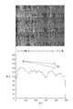
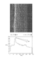
- the charge amount ⁇ (kV) of the non-woven fabric 20 is controlled. That is, the charge amount ⁇ (kV) increases as the basis weight W (g / m 2 ) increases (the thickness of the non-woven fabric 20 increases) so that “ ⁇ / W” is kept within a predetermined range. are doing. By doing so, the repulsive force between the fibers 11 increases as the thickness of the non-woven fabric 20 increases. Therefore, as shown in FIGS. 3 and 4, one end surface (the surface on the collector 52 side in the present embodiment). A non-woven fabric 20 whose pore diameter changes (expands in this embodiment) without a boundary from the other end surface (the surface on the nozzle 25a side in the present embodiment) can be obtained.
- FIGS. 3 and 4 the upper part of the figure shows a cross-sectional enlarged image of the non-woven fabric 20 manufactured by controlling the charge amount ⁇ (kV) so as to satisfy “0.03 ⁇ / W ⁇ 0.15”.
- the lower part of the figure shows the luminance (luminance of the enlarged cross-sectional image) at each position in the thickness direction of the nonwoven fabric 20.
- FIG. 3 shows the non-woven fabric 20 formed without the heating step
- FIG. 4 shows the non-woven fabric 20 formed through the heating step (the non-woven fabric 20 of FIG. 3 is heated in the heating step). Is shown.
- the fiber 11 appears white and the holes appear black in the enlarged cross-sectional image. That is, in the cross-sectional enlarged image, the brightness of the fiber 11 portion is high and the brightness of the hole portion is low. Therefore, the higher the brightness of the enlarged cross-section image, the denser the fiber 11 (higher fiber density) and the smaller the pore diameter. On the contrary, the lower the brightness, the sparser the fiber 11 (lower fiber density) and the larger the pore diameter. Is shown. Then, from FIGS. 3 and 4, the non-woven fabric 20 manufactured by controlling the charge amount ⁇ (kV) so as to satisfy “0.03 ⁇ / W ⁇ 0.15” is from the collector 52 side to the nozzle 25a side.
- the objects to be removed are concentrated on the boundary portion between the layers as in the case where two non-woven fabrics having different pore diameters are laminated and used as a filter. It is particularly suitable when used as a filter because it does not end up.
- the charge amount ⁇ (kV) and the basis weight W (g / m 2 ) indicate real-time values at one time point of the concentration of the fiber 11. That is, as described above, the charge amount ⁇ (kV) indicates the charge amount of the real tie measured by the charge amount meter 29.
- the basis weight W (g / m 2 ) the real-time basis weight is calculated and used based on the amount of the solution 23a ejected from the nozzle 25a.
- the present invention is not limited to this, and the final values at the time when the collection of the fiber 11 is completed may be used as the charge amount ⁇ (kV) and the basis weight W (g / m 2 ).
- the example of using the measured value measured by the charge meter 29 as the charge amount ⁇ (kV) has been described, but the charge amount meter 29 is abolished and the theory is set as the charge amount ⁇ (kV).
- the theoretical value of the charge amount ⁇ (kV) may be calculated based on the applied voltage of the power supply 27 and the charge amount of the static elimination wind from the static eliminator 28.
- the theoretical value calculated based on the amount of the solution 23a ejected from the nozzle 25a is used as the basis weight W (g / m 2 ), but the present invention is limited to this. Not done.
- the final basis weight W (g / m 2 ) at the time when the collection of the fiber 11 is completed the measured value obtained by actually measuring the weight per unit area of the manufactured nonwoven fabric 20 is used. It can also be used.
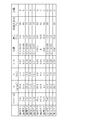
- FIG. 5 shows the verification results for verifying the relationship between the charge amount ⁇ (kV) and the basis weight W (g / m 2 ).
- the charge amount ⁇ (kV) is in the range of “0.03 ⁇ / W ⁇ 0.15” as an application example (application examples 1 to 8), and the charge amount ⁇ (kV) is “0.
- Reference examples (reference examples 1 to 3) are those outside the range of 03 ⁇ / W ⁇ 0.15 ", and the charge amount ⁇ (kV) and the grain in these application examples 1 to 8 and reference examples 1 to 3 are used.
- the non-woven fabric 20 was produced by using different W (g / m 2 ), fiber material, solvent, and concentration. Then, the fiber density ratio was calculated for each of the nonwoven fabrics 20 of Application Examples 1 to 8 and Reference Examples 1 to 3 produced in this manner, and evaluated based on the calculated fiber density ratio.
- the final values at the time when the collection of the fiber 11 is completed are used as the basis weight W (g / m 2 ) and the charge amount ⁇ (kV), and this value is also used for ⁇ / W. Is calculated.
- the concentration is a value of ⁇ M1 / (M1 + M2) ⁇ ⁇ 100 when the mass of the fiber material is M1 and the mass of the solvent is M2.
- the fiber density ratio is a value obtained by calculating the ratio of the fiber density (brightness of the cross-sectional image) on the other end surface side to the fiber density (brightness of the cross-sectional image) on the one end surface side of the nonwoven fabric 20.
- the evaluation was that the fiber density ratio was less than 80% and the change in pore diameter in the thickness direction was sufficiently large as "A”, and the fiber density ratio of 80% or more was less than 90% in the thickness direction.
- the one with a large change in pore size is "B”
- the one with a fiber density ratio of 90% or more is less than 95%
- the one with a confirmed change in pore diameter in the thickness direction is "C”
- the fiber density ratio is 95% or more. Therefore, it was designated as "D” that it was difficult to confirm the change in the hole diameter in the thickness direction.
- the production conditions and evaluations of the nonwoven fabrics 20 of Application Examples 1 to 8 and Reference Examples 1 to 3 are as shown in FIG.
- Reference Example 2 since the fiber 11 was unraveled and the non-woven fabric 20 could not be peeled from the support 30, the fiber density ratio could not be calculated. Therefore, the fiber density ratio was described as "-" and the evaluation was set to "D". There is.
- the charge amount ⁇ (kV) within the range of "0.03 ⁇ / W ⁇ 0.15", it is possible to cause a change in the pore diameter in the thickness direction, and in particular, a filter. It was confirmed that an effective non-woven fabric 20 can be produced when used as.
- the relationship between the amount of charge ⁇ (kV) and the basis weight W (g / m 2 ) is preferably 0.05 ⁇ / W ⁇ 0.13, more preferably 0.09 ⁇ / W ⁇ 0.12.
- Non-woven fabric manufacturing equipment 11 Fiber 20 Non-woven fabric 23 Solution adjustment part 23a Solution 24 Non-woven fabric manufacturing part 25 Nozzle unit 25a Nozzle 26 Integrated part 27 Power supply 28 Static eliminator 29 Charge meter 30 Support 52 Collector 57 Support supply part 58 Support winding Part 61, 62 Roller
Landscapes
- Engineering & Computer Science (AREA)
- Textile Engineering (AREA)
- Chemical & Material Sciences (AREA)
- Chemical Kinetics & Catalysis (AREA)
- General Chemical & Material Sciences (AREA)
- Mechanical Engineering (AREA)
- Dispersion Chemistry (AREA)
- Nonwoven Fabrics (AREA)
- Spinning Methods And Devices For Manufacturing Artificial Fibers (AREA)
Abstract
Description
11 ファイバ
20 不織布
23 溶液調整部
23a 溶液
24 不織布製造部
25 ノズルユニット
25a ノズル
26 集積部
27 電源
28 除電器
29 帯電量計
30 支持体
52 コレクタ
57 支持体供給部
58 支持体巻取部
61、62 ローラ
Claims (7)
- 溶媒にファイバ材が溶解している溶液とコレクタとの間に電圧を印加し、前記溶液を前記コレクタへ向けて噴出することにより形成したファイバを、前記コレクタで不織布として捕集する不織布製造方法において、
前記不織布の目付をW(g/m2 )、帯電量の絶対値を∨(kV)としたときに、
0.03<∨/W<0.15
を満たす不織布製造方法。 - 2(kV)≦∨(kV)≦20(kV)
を満たす請求項1記載の不織布製造方法。 - 前記溶媒は、複数の化合物の混合物である請求項1または2記載の不織布製造方法。
- 前記溶媒の沸点が80℃以下である請求項1~3のいずれか1項に記載の不織布製造方法。
- 前記溶媒は、ジクロロメタンとメタノールとを含む請求項1~4のいずれか1項に記載の不織布製造方法。
- 前記ファイバ材が、セルロース系ポリマーである請求項1~5のいずれか1項に記載の不織布製造方法。
- 前記セルロース系ポリマーは、セルロースアシレートである請求項6記載の不織布製造方法。
Priority Applications (3)
| Application Number | Priority Date | Filing Date | Title |
|---|---|---|---|
| JP2021507121A JP7150972B2 (ja) | 2019-03-19 | 2020-02-20 | 不織布製造方法 |
| KR1020217029924A KR20210126115A (ko) | 2019-03-19 | 2020-02-20 | 부직포 제조 방법 |
| CN202080022150.6A CN113597482A (zh) | 2019-03-19 | 2020-02-20 | 无纺布制造方法 |
Applications Claiming Priority (2)
| Application Number | Priority Date | Filing Date | Title |
|---|---|---|---|
| JP2019050644 | 2019-03-19 | ||
| JP2019-050644 | 2019-03-19 |
Publications (1)
| Publication Number | Publication Date |
|---|---|
| WO2020189170A1 true WO2020189170A1 (ja) | 2020-09-24 |
Family
ID=72520245
Family Applications (1)
| Application Number | Title | Priority Date | Filing Date |
|---|---|---|---|
| PCT/JP2020/006826 Ceased WO2020189170A1 (ja) | 2019-03-19 | 2020-02-20 | 不織布製造方法 |
Country Status (4)
| Country | Link |
|---|---|
| JP (1) | JP7150972B2 (ja) |
| KR (1) | KR20210126115A (ja) |
| CN (1) | CN113597482A (ja) |
| WO (1) | WO2020189170A1 (ja) |
Citations (5)
| Publication number | Priority date | Publication date | Assignee | Title |
|---|---|---|---|---|
| JP2004238749A (ja) * | 2003-02-04 | 2004-08-26 | Japan Vilene Co Ltd | 静電紡糸方法及び静電紡糸装置 |
| JP2008223187A (ja) * | 2007-03-14 | 2008-09-25 | Mecc Co Ltd | ナノ・ファイバ製造方法および装置 |
| JP2009052163A (ja) * | 2007-08-24 | 2009-03-12 | Panasonic Corp | 高分子ウエブの製造方法と装置 |
| JP2009256824A (ja) * | 2008-04-15 | 2009-11-05 | Panasonic Corp | ナノファイバ製造装置、不織布製造装置、ナノファイバ製造方法 |
| JP2016176151A (ja) * | 2015-03-18 | 2016-10-06 | 株式会社東芝 | ナノファイバ製造装置、及び、ナノファイバ製造方法 |
Family Cites Families (8)
| Publication number | Priority date | Publication date | Assignee | Title |
|---|---|---|---|---|
| JP4695430B2 (ja) * | 2005-04-12 | 2011-06-08 | 帝人株式会社 | 円筒体および円筒体の製造方法 |
| JP4669363B2 (ja) * | 2005-09-28 | 2011-04-13 | 帝人株式会社 | 静電紡糸法により繊維構造体を製造する装置および方法 |
| US8187520B2 (en) * | 2006-02-01 | 2012-05-29 | Toray Industries, Inc. | Nonwoven fabric for filters and method of producing the same |
| US20100180558A1 (en) * | 2007-05-31 | 2010-07-22 | Toray Industries, Inc | Nonwoven fabric for cylindrical bag filter, process for producing the same, and cylindrical bag filter therefrom |
| JP5425553B2 (ja) * | 2009-07-22 | 2014-02-26 | 王子キノクロス株式会社 | エアーフィルター用不織布 |
| JP5475541B2 (ja) * | 2010-05-07 | 2014-04-16 | 日本バイリーン株式会社 | 帯電フィルタ及びマスク |
| WO2012014501A1 (ja) * | 2010-07-29 | 2012-02-02 | 三井化学株式会社 | 繊維不織布、およびその製造方法と製造装置 |
| TWI675947B (zh) * | 2015-06-30 | 2019-11-01 | 日商可樂麗股份有限公司 | 不織布及其之製造方法 |
-
2020
- 2020-02-20 WO PCT/JP2020/006826 patent/WO2020189170A1/ja not_active Ceased
- 2020-02-20 JP JP2021507121A patent/JP7150972B2/ja active Active
- 2020-02-20 KR KR1020217029924A patent/KR20210126115A/ko not_active Withdrawn
- 2020-02-20 CN CN202080022150.6A patent/CN113597482A/zh not_active Withdrawn
Patent Citations (5)
| Publication number | Priority date | Publication date | Assignee | Title |
|---|---|---|---|---|
| JP2004238749A (ja) * | 2003-02-04 | 2004-08-26 | Japan Vilene Co Ltd | 静電紡糸方法及び静電紡糸装置 |
| JP2008223187A (ja) * | 2007-03-14 | 2008-09-25 | Mecc Co Ltd | ナノ・ファイバ製造方法および装置 |
| JP2009052163A (ja) * | 2007-08-24 | 2009-03-12 | Panasonic Corp | 高分子ウエブの製造方法と装置 |
| JP2009256824A (ja) * | 2008-04-15 | 2009-11-05 | Panasonic Corp | ナノファイバ製造装置、不織布製造装置、ナノファイバ製造方法 |
| JP2016176151A (ja) * | 2015-03-18 | 2016-10-06 | 株式会社東芝 | ナノファイバ製造装置、及び、ナノファイバ製造方法 |
Also Published As
| Publication number | Publication date |
|---|---|
| KR20210126115A (ko) | 2021-10-19 |
| CN113597482A (zh) | 2021-11-02 |
| JP7150972B2 (ja) | 2022-10-11 |
| JPWO2020189170A1 (ja) | 2021-12-23 |
Similar Documents
| Publication | Publication Date | Title |
|---|---|---|
| JP5637479B2 (ja) | ナノファイバーの製造装置 | |
| US20170130364A1 (en) | Nanofiber manufacturing method and nanofiber manufacturing device | |
| JP6205330B2 (ja) | 電界紡糸ノズル、ナノファイバ製造装置及び方法 | |
| JP5883614B2 (ja) | ナノファイバー積層体の製造方法 | |
| KR102212974B1 (ko) | 시트 및 시트 제조 방법 | |
| JP4602752B2 (ja) | 撚糸、撚糸の製造方法および撚糸の製造装置 | |
| JP5287242B2 (ja) | 極細繊維およびその製造方法 | |
| JP7150972B2 (ja) | 不織布製造方法 | |
| WO2019021757A1 (ja) | 不織布製造方法及び装置 | |
| JP2008075197A (ja) | 静電紡糸不織布及び静電紡糸不織布の製造方法 | |
| JP6170889B2 (ja) | ナノファイバ製造方法及び装置、不織布製造方法 | |
| CN106012290A (zh) | 无纺布及碳纤维无纺布 | |
| JP2002115178A (ja) | エレクトレット加工品の製造方法 | |
| JP5225885B2 (ja) | ナノファイバ製造装置、および製造方法 | |
| JP7167302B2 (ja) | 不織布製造方法 | |
| JP7508543B2 (ja) | 不織布製造方法 | |
| JP2018138280A (ja) | 帯電繊維及び帯電繊維の製造方法 | |
| JP4890049B2 (ja) | 極細繊維集合体 | |
| JP4695430B2 (ja) | 円筒体および円筒体の製造方法 | |
| JP2017197874A (ja) | 積層体、その製造方法および製造装置 | |
| JP6464486B2 (ja) | 積層体の製造方法および製造装置 | |
| JP2016160568A (ja) | 不織布およびその製造方法 | |
| JP2015203164A (ja) | ナノファイバー製造方法およびナノファイバー製造装置 | |
| JP4907139B2 (ja) | 繊維集合体の製造方法及びその製造装置 | |
| WO2022054378A1 (ja) | 不織布、不織布製造方法、液体用フィルタ |
Legal Events
| Date | Code | Title | Description |
|---|---|---|---|
| 121 | Ep: the epo has been informed by wipo that ep was designated in this application |
Ref document number: 20772635 Country of ref document: EP Kind code of ref document: A1 |
|
| ENP | Entry into the national phase |
Ref document number: 2021507121 Country of ref document: JP Kind code of ref document: A |
|
| ENP | Entry into the national phase |
Ref document number: 20217029924 Country of ref document: KR Kind code of ref document: A |
|
| NENP | Non-entry into the national phase |
Ref country code: DE |
|
| 122 | Ep: pct application non-entry in european phase |
Ref document number: 20772635 Country of ref document: EP Kind code of ref document: A1 |