WO2020189151A1 - 車両用灯具 - Google Patents
車両用灯具 Download PDFInfo
- Publication number
- WO2020189151A1 WO2020189151A1 PCT/JP2020/006317 JP2020006317W WO2020189151A1 WO 2020189151 A1 WO2020189151 A1 WO 2020189151A1 JP 2020006317 W JP2020006317 W JP 2020006317W WO 2020189151 A1 WO2020189151 A1 WO 2020189151A1
- Authority
- WO
- WIPO (PCT)
- Prior art keywords
- base
- lamp
- unit
- light emitting
- lighting
- Prior art date
- Legal status (The legal status is an assumption and is not a legal conclusion. Google has not performed a legal analysis and makes no representation as to the accuracy of the status listed.)
- Ceased
Links
Images




Classifications
-
- B—PERFORMING OPERATIONS; TRANSPORTING
- B60—VEHICLES IN GENERAL
- B60Q—ARRANGEMENT OF SIGNALLING OR LIGHTING DEVICES, THE MOUNTING OR SUPPORTING THEREOF OR CIRCUITS THEREFOR, FOR VEHICLES IN GENERAL
- B60Q1/00—Arrangement of optical signalling or lighting devices, the mounting or supporting thereof or circuits therefor
- B60Q1/26—Arrangement of optical signalling or lighting devices, the mounting or supporting thereof or circuits therefor the devices being primarily intended to indicate the vehicle, or parts thereof, or to give signals, to other traffic
- B60Q1/30—Arrangement of optical signalling or lighting devices, the mounting or supporting thereof or circuits therefor the devices being primarily intended to indicate the vehicle, or parts thereof, or to give signals, to other traffic for indicating rear of vehicle, e.g. by means of reflecting surfaces
-
- B—PERFORMING OPERATIONS; TRANSPORTING
- B60—VEHICLES IN GENERAL
- B60Q—ARRANGEMENT OF SIGNALLING OR LIGHTING DEVICES, THE MOUNTING OR SUPPORTING THEREOF OR CIRCUITS THEREFOR, FOR VEHICLES IN GENERAL
- B60Q1/00—Arrangement of optical signalling or lighting devices, the mounting or supporting thereof or circuits therefor
- B60Q1/0029—Spatial arrangement
- B60Q1/0041—Spatial arrangement of several lamps in relation to each other
- B60Q1/0058—Stacked, i.e. one lamp located behind the other in the optical axis direction
-
- B—PERFORMING OPERATIONS; TRANSPORTING
- B60—VEHICLES IN GENERAL
- B60Q—ARRANGEMENT OF SIGNALLING OR LIGHTING DEVICES, THE MOUNTING OR SUPPORTING THEREOF OR CIRCUITS THEREFOR, FOR VEHICLES IN GENERAL
- B60Q1/00—Arrangement of optical signalling or lighting devices, the mounting or supporting thereof or circuits therefor
- B60Q1/26—Arrangement of optical signalling or lighting devices, the mounting or supporting thereof or circuits therefor the devices being primarily intended to indicate the vehicle, or parts thereof, or to give signals, to other traffic
- B60Q1/50—Arrangement of optical signalling or lighting devices, the mounting or supporting thereof or circuits therefor the devices being primarily intended to indicate the vehicle, or parts thereof, or to give signals, to other traffic for indicating other intentions or conditions, e.g. request for waiting or overtaking
-
- F—MECHANICAL ENGINEERING; LIGHTING; HEATING; WEAPONS; BLASTING
- F21—LIGHTING
- F21S—NON-PORTABLE LIGHTING DEVICES; SYSTEMS THEREOF; VEHICLE LIGHTING DEVICES SPECIALLY ADAPTED FOR VEHICLE EXTERIORS
- F21S43/00—Signalling devices specially adapted for vehicle exteriors, e.g. brake lamps, direction indicator lights or reversing lights
- F21S43/10—Signalling devices specially adapted for vehicle exteriors, e.g. brake lamps, direction indicator lights or reversing lights characterised by the light source
- F21S43/13—Signalling devices specially adapted for vehicle exteriors, e.g. brake lamps, direction indicator lights or reversing lights characterised by the light source characterised by the type of light source
- F21S43/14—Light emitting diodes [LED]
-
- F—MECHANICAL ENGINEERING; LIGHTING; HEATING; WEAPONS; BLASTING
- F21—LIGHTING
- F21S—NON-PORTABLE LIGHTING DEVICES; SYSTEMS THEREOF; VEHICLE LIGHTING DEVICES SPECIALLY ADAPTED FOR VEHICLE EXTERIORS
- F21S43/00—Signalling devices specially adapted for vehicle exteriors, e.g. brake lamps, direction indicator lights or reversing lights
- F21S43/10—Signalling devices specially adapted for vehicle exteriors, e.g. brake lamps, direction indicator lights or reversing lights characterised by the light source
- F21S43/13—Signalling devices specially adapted for vehicle exteriors, e.g. brake lamps, direction indicator lights or reversing lights characterised by the light source characterised by the type of light source
- F21S43/15—Strips of light sources
-
- F—MECHANICAL ENGINEERING; LIGHTING; HEATING; WEAPONS; BLASTING
- F21—LIGHTING
- F21S—NON-PORTABLE LIGHTING DEVICES; SYSTEMS THEREOF; VEHICLE LIGHTING DEVICES SPECIALLY ADAPTED FOR VEHICLE EXTERIORS
- F21S43/00—Signalling devices specially adapted for vehicle exteriors, e.g. brake lamps, direction indicator lights or reversing lights
- F21S43/10—Signalling devices specially adapted for vehicle exteriors, e.g. brake lamps, direction indicator lights or reversing lights characterised by the light source
- F21S43/19—Attachment of light sources or lamp holders
- F21S43/195—Details of lamp holders, terminals or connectors
-
- F—MECHANICAL ENGINEERING; LIGHTING; HEATING; WEAPONS; BLASTING
- F21—LIGHTING
- F21V—FUNCTIONAL FEATURES OR DETAILS OF LIGHTING DEVICES OR SYSTEMS THEREOF; STRUCTURAL COMBINATIONS OF LIGHTING DEVICES WITH OTHER ARTICLES, NOT OTHERWISE PROVIDED FOR
- F21V19/00—Fastening of light sources or lamp holders
-
- B—PERFORMING OPERATIONS; TRANSPORTING
- B60—VEHICLES IN GENERAL
- B60Q—ARRANGEMENT OF SIGNALLING OR LIGHTING DEVICES, THE MOUNTING OR SUPPORTING THEREOF OR CIRCUITS THEREFOR, FOR VEHICLES IN GENERAL
- B60Q2400/00—Special features or arrangements of exterior signal lamps for vehicles
- B60Q2400/40—Welcome lights, i.e. specific or existing exterior lamps to assist leaving or approaching the vehicle
-
- B—PERFORMING OPERATIONS; TRANSPORTING
- B60—VEHICLES IN GENERAL
- B60Q—ARRANGEMENT OF SIGNALLING OR LIGHTING DEVICES, THE MOUNTING OR SUPPORTING THEREOF OR CIRCUITS THEREFOR, FOR VEHICLES IN GENERAL
- B60Q2900/00—Features of lamps not covered by other groups in B60Q
- B60Q2900/40—Several lamps activated in sequence, e.g. sweep effect, progressive activation
Definitions
- the present invention relates to a vehicle lamp.
- Vehicle lighting fixtures with a novel look and increased commercial value have been realized.
- a vehicle lamp has been proposed in which light is incident on a rod-shaped light guide from an end face, and the light incident from the end face is reflected by a reflection step provided on the peripheral surface and emitted to the front of the lamp (for example).
- Patent Document 1 Japanese Patent Document 1
- the present invention has been made in such a situation, and one of the exemplary purposes of the present invention is to provide a vehicle lamp with enhanced commercial value.
- a vehicle lamp includes a first base having translucency, a first light source held by the first base and irradiating light toward the front of the lamp, and the like. It includes a second base arranged behind the lamp of the first base, and a second light source held by the second base and irradiating light toward the front of the lamp. The light from the second light source passes through the first base and is emitted to the front of the lamp.
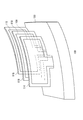
- FIG. 1 is a horizontal sectional view showing a schematic structure of a vehicle lighting tool 100 according to an embodiment.
- FIG. 2 is a perspective view showing a schematic structure of the vehicle lighting equipment 100 according to the embodiment.
- the display of the lamp body 102 and the outer cover 104 is omitted.
- the vehicle lighting tool 100 is used, for example, as a tail lamp mounted on the rear part of the vehicle.
- the vehicle lamp 100 may be used as a stop lamp or other lamp.
- the vehicle lamp 100 is housed in a lamp body 102 having an opening, a translucent outer cover 104 covering the opening of the lamp body 102, and a lamp chamber 106 formed by the lamp body 102 and the outer cover 104.
- the first base 114 and the second base supporting the first lamp unit 108, the second lamp unit 110, and the third lamp unit 112, and the first lamp unit 108, the second lamp unit 110, and the third lamp unit 112, respectively. It includes 116, a third base 118, and a control unit 120.
- the first base 114 is made of a translucent resin, glass, or the like.
- the first base 114 has a plate-like shape and is curved along the shape of the outer cover 104.
- the second base 116 and the third base 118 are configured in the same manner as the first base 114, the second base 116 is arranged behind the lamp of the first base 114, and the third base 118 is arranged behind the lamp of the second base 116. Will be done.
- the first base 114, the second base 116, and the third base 118 are supported by the housing of the control unit 120.
- FIG. 3 is a schematic cross-sectional view showing a part of the first lamp unit 108 and its surroundings in an enlarged manner.
- the first lamp unit 108 includes a substrate 122 and a plurality of light emitting elements 124 as a main configuration.
- the first lighting equipment unit 108 is attached to the front surface of the lighting equipment of the first base 114 with a transparent adhesive (not shown).
- the first lighting unit 108 is flexible and curves along the first base 114.
- the substrate 122 is a transparent and flexible substrate (for example, can be bent arbitrarily like paper), and has two insulating films 130 and a conductive pattern 132 arranged between the two insulating films 130. , Equipped with.
- the insulating film 130 is transparent and consists of, for example, PET (polyethylene terephthalate) or other suitable resin material.
- the conductive pattern 132 is provided to supply electric power to the plurality of light emitting elements 124.
- the conductive pattern 132 is made of, for example, ITO (indium tin oxide) or other suitable conductive material.
- the substrate 122 also includes an adhesive layer 134, which is also called an intermediate resin.
- the adhesive layer 134 is provided to bond the two insulating films 130 to each other.
- the conductive pattern 132 is formed on the inner surface of one of the two insulating films 130.
- the conductive pattern 132, together with the plurality of light emitting elements 124, is sandwiched between the two insulating films 130 by the adhesive layer 134. Therefore, the conductive pattern 132 and the plurality of light emitting elements 124 are substantially sealed by the two insulating films 130.
- the plurality of light emitting elements 124 are arranged between the two insulating films 130 and are electrically connected to the conductive pattern 132.
- the plurality of light emitting elements 124 are, for example, LEDs (light emitting diodes).
- the light emitting element 124 may be another semiconductor light emitting device.
- the light emitted from the light emitting element 124 passes through one of the two insulating films 130 and is emitted from the substrate 122.
- the first lamp unit 108 is attached to the first base 114 so that the light emitted from the light emitting element 124 is emitted to the front of the lamp. Since the light emitting element 124 is supported by the substrate 122 and thus the transparent first base 114, it is visually recognized as if it is floating in the air.
- the number of light emitting elements 124 is not particularly limited and may be one.
- the second lighting equipment unit 110 is configured in the same manner as the first lighting equipment unit 108.
- the second lamp unit 110 is attached to the second base 116 with a transparent adhesive so that the light emitted from the light emitting element is emitted to the front of the lamp.
- the light emitted from the second lamp unit 110 passes through the first base 114 and the first lamp unit 108 and is emitted in front of the lamp. Since the light emitting element of the second lamp unit 110 is supported by the substrate and thus the transparent second base 116, it is visually recognized as if it is floating in the air.
- the second lighting unit 110 includes the same number of light emitting elements as the first lighting unit 108, but the number of light emitting elements is not particularly limited, and a different number of light emitting elements from the first lighting unit 108 is provided. You may prepare.
- the third lighting unit 112 is also configured in the same manner as the first lighting unit 108.
- the third lamp unit 112 is attached to the third base 118 with a transparent adhesive so that the light emitted from the light emitting element is emitted to the front of the lamp.
- the light emitted from the third lamp unit 112 passes through the second base 116 and the second lamp unit 110, further passes through the first base 114 and the first lamp unit 108, and is emitted to the front of the lamp. Since the light emitting element of the third lamp unit 112 is supported by the substrate and thus the transparent third base 118, it is visually recognized as if it is floating in the air.
- the third lighting unit 112 includes the same number of light emitting elements as the first lighting unit 108 and the second lighting unit 110, but the number of light emitting elements is not particularly limited, and the first lighting unit 108 and the like. A different number of light emitting elements than the second lighting unit 110 may be provided.
- the control unit 120 controls turning on and off the first lighting unit 108, the second lighting unit 110, and the third lighting unit 112.
- FIG. 4 is a diagram showing an arrangement of a plurality of light emitting elements 124 of the first lamp unit 108.
- the plurality of light emitting elements 124 of the second lighting unit 110 and the plurality of light emitting elements 124 of the third lighting unit 112 are each the plurality of light emitting elements 124 of the first lighting unit 108. Is arranged in the same way as.
- the plurality of light emitting elements 124 form three concentric angle groups each including three concentric angles (concentric squares) so as to form at least one concentric shape group in the present embodiment.
- three concentric angle groups each including three concentric angles (concentric squares) so as to form at least one concentric shape group in the present embodiment.
- the dotted line indicates the grouping of the plurality of light emitting elements 124, and the light emitting elements 124 in the same dotted line (that is, in the same group) are electrically connected in series or in parallel. That is, the dotted line indicates a control unit of the plurality of light emitting elements 124.
- each dotted line contains substantially the same number of light emitting elements, that is, substantially the same number of light emitting elements are electrically connected in series or in parallel. As a result, substantially the same amount of drive current may be supplied to each group.
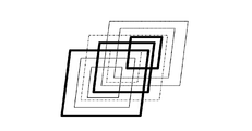
- FIG. 5 is a diagram showing a state when the vehicle lamp 100 is functioning as a tail lamp.
- the thick black line indicates that the light emitting element 124 on the thick black line is emitting light.
- the thin solid line indicates the concentric angle in which the light emitting elements of the first lamp unit 108 are arranged
- the thin alternate long and short dash line indicates the concentric angle in which the light emitting elements of the second lamp unit 110 are arranged
- the thin dotted line indicates the concentric angle in which the light emitting elements of the second lamp unit 110 are arranged.
- the light emitting element 124 on the outermost square of the three concentric angles is lit (light emitting), and for the second lighting unit 110, among the three concentric angles.
- the light emitting element on the center square is lit, and for the third lamp unit 112, the light emitting element on the innermost square of the three concentric angles is lit.
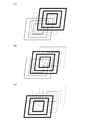
- FIG. 6A to 6 (c) are views when the vehicle lamp 100 is functioning as, for example, a hospitality lamp, and are diagrams showing the lighting of each lamp unit in chronological order.
- the hospitality lamp is a lamp that lights up when a person who meets certain conditions, such as the proximity of a person who owns a key, approaches the vehicle while the vehicle is parked.
- FIG. 6A the first lighting unit 108 and the second lighting unit 110 are turned off, and the third lighting unit 112 is turned on.
- FIG. 6B the first lighting unit 108 and the third lighting unit 112 are turned off, and the second lighting unit 110 is turned on.
- FIG. 6A the first lighting unit 108 and the second lighting unit 110 are turned off, and the third lighting unit 112 is turned on.
- FIG. 6B the first lighting unit 108 and the third lighting unit 112 are turned off, and the second lighting unit 110 is turned on.
- the second lighting unit 110 and the third lighting unit 112 are turned off, and the second lighting unit 110 is turned on.
- the first lighting unit 108, the second lighting unit 110, and the third lighting unit 112 with a time lag, it is possible to realize a novel way of shining in which the light emission appears to move in the depth direction.
- FIG. 7 (a) to 7 (c) are views when the vehicle lamp 100 is functioning as, for example, a hospitality lamp, and are diagrams showing the lighting of each lamp unit in chronological order.
- FIG. 7A the light emitting elements on all the three concentric angles of the third lamp unit 112 are lit.
- FIG. 7B for the third lamp unit 112, only the light emitting element on the outermost square of the three concentric angles lights up, that is, the middle and innermost squares.
- the upper light emitting element is turned off, and for the second lamp unit 110, the light emitting element on the center and innermost squares of the three concentric angles is turned on.
- the first lamp unit 108 all the light emitting elements 124 are turned off.
- the light emitting element on the outermost square of the three concentric angles of the third lighting unit 112 lights up, and the second lighting unit 110 lights up. Only the light emitting element in the middle of the three concentric angles lights up, that is, the light emitting element on the innermost square turns off, and for the first lamp unit 108, the innermost square of the three concentric angles The upper light emitting element is lit. In this case as well, it is possible to realize a novel way of shining in which the light emission appears to move in the depth direction.
- various ways of shining can be realized, such as lighting in a spiral shape.
- the first lamp unit 108, the second lamp unit 110, and the third lamp unit 12 are lit with a time lag, so that a novel way of shining that moves in the depth direction can be realized, for example. It can be used as a production of hospitality.
- each lamp unit is attached to the front surface of the corresponding base lamp. If the lamp is attached to the rear surface of the lamp, the light emitted from the lamp unit will pass through the adhesive for attaching the lamp unit to the base, and the light utilization efficiency will be reduced accordingly. To do. On the other hand, if it is attached to the surface on the front side of the lamp, the decrease in light utilization efficiency can be suppressed.
- Each lamp unit may be configured so as not to block light from the lamp unit arranged behind the lamp, and is not limited to the configuration of the embodiment.
- At least one of the first lamp unit 108, the second lamp unit 110, and the third lamp unit 112 may have a wire pattern and a light emitting element arranged directly on the base.
- two insulating films are not required, or one insulating film that protects the wire pattern and the light emitting element is sufficient.
- At least one of the first lighting unit 108, the second lighting unit 110, and the third lighting unit 112 may be a transparent organic EL panel, for example, a transparent OLED (Organic Light Emitting Diode) panel.
- a transparent organic EL panel for example, a transparent OLED (Organic Light Emitting Diode) panel.
- OLED Organic Light Emitting Diode
- each lighting unit is held by the base has been described, but the vehicle lighting 100 does not have a base, and each lighting unit may be held around, for example, by a bracket (not shown).
- the light utilization efficiency of the second lamp unit 110 and the third lamp unit 112 can be improved because there is no base.
- the first base, the second base, and the third base according to the claim are the insulating film of the first lighting equipment unit 108, the insulating film of the second lighting equipment unit 110, and the insulation of the third lighting equipment unit 112, respectively. It may be realized by a film.
- the present invention can be used for vehicle lamps.
Landscapes
- Engineering & Computer Science (AREA)
- Mechanical Engineering (AREA)
- General Engineering & Computer Science (AREA)
- Physics & Mathematics (AREA)
- Microelectronics & Electronic Packaging (AREA)
- Optics & Photonics (AREA)
- Non-Portable Lighting Devices Or Systems Thereof (AREA)
Abstract
車両用灯具(100)は、透光性を有する第1ベース(114)と、第1ベース(114)に保持され、灯具前方に向けて光を照射する第1光源と、第1ベース(114)の灯具後方に配置される第2ベース(116)と、第2ベース(116)に保持され、灯具前方に向けて光を照射する第2光源と、を備える。第2光源からの光は、第1ベース(114)を透過して灯具前方に出射される。
Description
本発明は、車両用灯具に関する。
斬新な見映えを実現して商品価値を高めた車両用灯具が実現されている。従来では例えば、棒状の導光体に端面から光を入射させ、端面から入射した光を周面に設けられた反射ステップによって反射させて灯具前方へ出射する車両用灯具が提案されている(例えば特許文献1)。
本発明はこうした状況においてなされたものであり、そのある態様の例示的な目的のひとつは、商品価値を高めた車両用灯具の提供にある。
上記課題を解決するために、本発明のある態様の車両用灯具は、透光性を有する第1ベースと、第1ベースに保持され、灯具前方に向けて光を照射する第1光源と、第1ベースの灯具後方に配置される第2ベースと、第2ベースに保持され、灯具前方に向けて光を照射する第2光源と、を備える。第2光源からの光は、第1ベースを透過して灯具前方に出射される。
なお、以上の構成要素の任意の組み合わせや、本発明の構成要素や表現を、方法、装置、システムなどの間で相互に置換したものもまた、本発明の態様として有効である。
本発明によれば、商品価値を高めた車両用灯具を提供できる。
以下、本発明を好適な実施の形態をもとに図面を参照しながら説明する。実施の形態は、発明を限定するものではなく例示であって、実施の形態に記述されるすべての特徴やその組み合わせは、必ずしも発明の本質的なものであるとは限らない。各図面に示される同一または同等の構成要素、部材、処理には、同一の符号を付するものとし、適宜重複した説明は省略する。
図1は、実施の形態に係る車両用灯具100の概略構造を示す水平断面図である。図2は、実施の形態に係る車両用灯具100の概略構造を示す斜視図である。図2では、ランプボディ102とアウターカバー104の表示を省略している。車両用灯具100は、例えば車両後部に搭載されるテールランプとして用いられる。なお、車両用灯具100は、ストップランプ、その他のランプとして用いられてもよい。
車両用灯具100は、開口部を有するランプボディ102と、ランプボディ102の開口部を覆う透光性のアウターカバー104と、ランプボディ102とアウターカバー104とで形成される灯室106内に収容される第1灯具ユニット108、第2灯具ユニット110および第3灯具ユニット112と、第1灯具ユニット108、第2灯具ユニット110、第3灯具ユニット112をそれぞれ支持する第1ベース114、第2ベース116、第3ベース118と、制御ユニット120と、を備える。
第1ベース114は、透光性を有する樹脂やガラス等で形成されている。第1ベース114は、板状の形状を有し、アウターカバー104の形状に沿って湾曲している。第2ベース116および第3ベース118は第1ベース114と同様に構成され、第2ベース116は第1ベース114の灯具後方に配置され、第3ベース118は第2ベース116の灯具後方に配置される。第1ベース114、第2ベース116および第3ベース118は、制御ユニット120の筐体に支持されている。
図3は、第1灯具ユニット108の一部とその周辺を拡大して示す概略断面図である。第1灯具ユニット108は、基板122と、複数の発光素子124と、を主な構成として備える。第1灯具ユニット108は、第1ベース114の灯具前方側の面に、透明の接着剤(不図示)により貼り付けられている。第1灯具ユニット108は、柔軟性を有し、第1ベース114に沿って湾曲する。
基板122は、透光性を有するフレキシブル(例えば紙のように随意に曲げられる)な基板であり、二枚の絶縁フィルム130と、二枚の絶縁フィルム130の間に配置された導電パターン132と、を備える。絶縁フィルム130は、透明であり、例えばPET(ポリエチレンテレフタレート)またはその他の適切な樹脂材料からなる。導電パターン132は、複数の発光素子124に電力を供給するために設けられている。導電パターン132は、例えばITO(酸化インジウムスズ)その他の適切な導電材料からなる。
また、基板122は、中間樹脂とも称される接着層134を備える。接着層134は、二枚の絶縁フィルム130を互いに接着するために設けられている。導電パターン132は、二枚の絶縁フィルム130のうち一方の絶縁フィルム130の内側の面に形成されている。導電パターン132は、複数の発光素子124とともに、接着層134によって二枚の絶縁フィルム130の間に挟み込まれている。よって、導電パターン132および複数の発光素子124は、二枚の絶縁フィルム130によって概ね密閉されている。
複数の発光素子124は、二枚の絶縁フィルム130の間に配置され、導電パターン132に電気的に接続されている。複数の発光素子124は、例えば、LED(発光ダイオード)である。発光素子124は、他の半導体発光素子であってもよい。発光素子124から発せられる光は、二枚の絶縁フィルム130の一方を透過して、基板122から出射される。第1灯具ユニット108は、発光素子124から発せられる光が灯具前方に出射されるように第1ベース114に貼り付けられている。発光素子124は、基板122ひいては透明の第1ベース114に支持されるため、あたかも宙に浮いているかのように視認される。なお、発光素子124の数は特に限定されず、1つであってもよい。
図2に戻り、第2灯具ユニット110は、第1灯具ユニット108と同様に構成される。第2灯具ユニット110は、発光素子から発せられる光が灯具前方に出射されるように第2ベース116に透明の接着剤により貼り付けられている。第2灯具ユニット110から出射された光は、第1ベース114および第1灯具ユニット108を透過して、灯具前方に出射される。第2灯具ユニット110の発光素子は、基板ひいては透明の第2ベース116に支持されるため、あたかも宙に浮いているかのように視認される。なお、本実施の形態では、第2灯具ユニット110は第1灯具ユニット108と同数の発光素子を備えるが、発光素子の数は特に限定されず、第1灯具ユニット108と異なる数の発光素子を備えてもよい。
第3灯具ユニット112も、第1灯具ユニット108と同様に構成される。第3灯具ユニット112は、発光素子から発せられる光が灯具前方に出射されるように第3ベース118に透明の接着剤により貼り付けられている。第3灯具ユニット112から出射された光は、第2ベース116および第2灯具ユニット110を透過し、さらに第1ベース114および第1灯具ユニット108を透過して、灯具前方に出射される。第3灯具ユニット112の発光素子は、基板ひいては透明の第3ベース118に支持されるため、あたかも宙に浮いているかのように視認される。なお、本実施の形態では、第3灯具ユニット112は第1灯具ユニット108や第2灯具ユニット110と同数の発光素子を備えるが、発光素子の数は特に限定されず、第1灯具ユニット108や第2灯具ユニット110と異なる数の発光素子を備えてもよい。
制御ユニット120は、第1灯具ユニット108、第2灯具ユニット110および第3灯具ユニット112の点消灯を制御する。
図4は、第1灯具ユニット108の複数の発光素子124の配列を示す図である。なお、特に限定しないが、本実施の形態では、第2灯具ユニット110の複数の発光素子124、第3灯具ユニット112の複数の発光素子124はそれぞれ、第1灯具ユニット108の複数の発光素子124と同様に配列される。
複数の発光素子124は、本実施の形態では、少なくとも1つの同心形状群を形成するように、より具体的には、それぞれ3つの同心角(同心四角)を含む3つの同心角群を形成するように配列される。
図4において、点線は、複数の発光素子124のグループ分けを示し、同じ点線内(すなわち同じグループ内)の発光素子124は、直列または並列に電気的に接続されている。つまり、点線は、複数の発光素子124の制御の単位を示す。好ましくは、各点線内には実質的に同数の発光素子が含まれる、すなわち直列または並列に電気的に接続される発光素子は実質的に同数である。これにより、各グループには実質的に同一量の駆動電流を供給すればよい。
以上が車両用灯具100の基本構成である。続いてその動作を説明する。
図5は、車両用灯具100をテールランプとして機能させているときの様子を示す図である。ここでは、説明を容易にするために1つの同心角群上の発光素子について説明する。図5において、太い黒線は、当該太い黒線上の発光素子124が発光していることを示す。また、細い実線は、第1灯具ユニット108の発光素子が配列されている同心角を示し、細い一点鎖線は、第2灯具ユニット110の発光素子が配列されている同心角を示し、細い点線は、第3灯具ユニット112の発光素子が配列されている同心角を示す。
図5は、車両用灯具100をテールランプとして機能させているときの様子を示す図である。ここでは、説明を容易にするために1つの同心角群上の発光素子について説明する。図5において、太い黒線は、当該太い黒線上の発光素子124が発光していることを示す。また、細い実線は、第1灯具ユニット108の発光素子が配列されている同心角を示し、細い一点鎖線は、第2灯具ユニット110の発光素子が配列されている同心角を示し、細い点線は、第3灯具ユニット112の発光素子が配列されている同心角を示す。
図5では、第1灯具ユニット108については3つの同心角のうちの一番外側の四角上の発光素子124が点灯され(発光し)、第2灯具ユニット110については3つの同心角のうちの真ん中の四角上の発光素子が点灯され、第3灯具ユニット112については3つの同心角のうちの一番内側の四角上の発光素子が点灯されている。この場合、各灯具ユニットの灯具前後方向の距離差により、灯具前後方向に奥行きのある立体的な見映えを実現できる。
図6(a)~(c)は、車両用灯具100を例えばおもてなしランプとして機能させているときの様子であって、各灯具ユニットの点消灯の様子を時系列で示す図である。おもてなしランプとは、車両の駐車中に、例えばキーを所有している人物の近接など、所定の条件を満たす人物が当該車両に近接すると点灯するランプをいう。図6(a)に示される或るタイミングでは、第1灯具ユニット108および第2灯具ユニット110が消灯し、第3灯具ユニット112が点灯している。図6(b)に示される次のタイミングでは、第1灯具ユニット108および第3灯具ユニット112が消灯して、第2灯具ユニット110が点灯している。図6(c)に示されるさらに次のタイミングでは、第2灯具ユニット110および第3灯具ユニット112が消灯して、第2灯具ユニット110が点灯している。このように、第1灯具ユニット108、第2灯具ユニット110、第3灯具ユニット112を時間差で点灯することで、発光が奥行き方向に動いて見える斬新な光り方を実現できる。
図7(a)~(c)は、車両用灯具100を例えばおもてなしランプとして機能させているときの様子であって、各灯具ユニットの点消灯の様子を時系列で示す図である。図7(a)に示される或るタイミングでは、第3灯具ユニット112の3つの同心角のうちのすべての四角上の発光素子が点灯している。図7(b)に示される次のタイミングでは、第3灯具ユニット112については、3つの同心角のうちの一番外側の四角上の発光素子のみが点灯し、すなわち真ん中と一番内側の四角上の発光素子が消灯し、第2灯具ユニット110については、3つの同心角のうちの真ん中と一番内側の四角上の発光素子が点灯している。第1灯具ユニット108については、すべての発光素子124が消灯している。図7(c)に示されるさらに次のタイミングでは、第3灯具ユニット112については、3つの同心角のうちの一番外側の四角上の発光素子が点灯し、第2灯具ユニット110については、3つの同心角のうちの真ん中の発光素子のみが点灯し、すなわち一番内側の四角上の発光素子が消灯し、第1灯具ユニット108については、3つの同心角のうちの一番内側の四角上の発光素子が点灯している。この場合も、発光が奥行き方向に動いて見える斬新な光り方を実現できる。
ここに示した例以外にも、例えば渦巻き状に点灯させるなど、様々な光り方を実現できる。また、奥行き方向に加えて、横方向にも動きのある斬新な光方を実現することもできる。
続いて、以上説明した本実施の形態が奏する効果について述べる。本実施の形態によれば、立体感・奥行き感のある斬新な見映えの発光パターンを実現できる。
また、本実施の形態によれば、第1灯具ユニット108、第2灯具ユニット110、第3灯具ユニット12が時間差で点灯することで、奥行き方向に動きのある斬新な光り方を実現でき、例えばおもてなし感の演出として利用できる。
また、本実施の形態によれば、各灯具ユニットは、対応するベースの灯具前方側の面に貼り付けられる。仮に、灯具後方側の面に貼り付けられた場合、灯具ユニットから出射された光は、灯具ユニットをベースに貼り付けるための接着剤を透過することになり、その分、光の利用効率が低下する。これに対し灯具前方側の面に貼り付ければ、光の利用効率の低下を抑止できる。
以上、本発明について、実施の形態をもとに説明した。この実施の形態は例示であり、それらの各構成要素や各処理プロセスの組み合わせにいろいろな変形例が可能なこと、またそうした変形例も本発明の範囲にあることは当業者に理解されるところである。以下、こうした変形例について説明する。
(変形例1)
各灯具ユニットは、灯具後方に配置される灯具ユニットからの光を概ね遮らないように構成されていればよく、実施の形態の構成には限定されない。
各灯具ユニットは、灯具後方に配置される灯具ユニットからの光を概ね遮らないように構成されていればよく、実施の形態の構成には限定されない。
例えば、第1灯具ユニット108、第2灯具ユニット110および第3灯具ユニット112のうちの少なくとも1つは、導線パターンおよび発光素子がベースに直接配置されてもよい。この場合、2枚の絶縁フィルムが不要になる、あるいは、導線パターンおよび発光素子を保護する1枚の絶縁フィルムがあれば十分である。
また例えば、第1灯具ユニット108、第2灯具ユニット110および第3灯具ユニット112のうちの少なくとも1つは、透明な有機ELパネル、例えば透明なOLED(Organic Light Emitting Diode)パネルであってもよく、第1ベース114、第2ベース116、第3ベース118が湾曲している場合は、それらに沿って湾曲しうるようにフレキシブルな透明な有機ELパネルであってもよい。
(変形例2)
実施の形態では、各灯具ユニットがベースに保持される場合について説明したが、車両用灯具100がベースを備えず、各灯具ユニットは、例えばその周囲を不図示のブラケットに保持されてもよい。本変形例によれば、ベースがない分、第2灯具ユニット110および第3灯具ユニット112の光の利用効率を高めることができる。本変形例の場合、請求項に記載の第1ベース、第2ベース、第3ベースはそれぞれ、第1灯具ユニット108の絶縁フィルム、第2灯具ユニット110の絶縁フィルム、第3灯具ユニット112の絶縁フィルムにより実現されてもよい。
実施の形態では、各灯具ユニットがベースに保持される場合について説明したが、車両用灯具100がベースを備えず、各灯具ユニットは、例えばその周囲を不図示のブラケットに保持されてもよい。本変形例によれば、ベースがない分、第2灯具ユニット110および第3灯具ユニット112の光の利用効率を高めることができる。本変形例の場合、請求項に記載の第1ベース、第2ベース、第3ベースはそれぞれ、第1灯具ユニット108の絶縁フィルム、第2灯具ユニット110の絶縁フィルム、第3灯具ユニット112の絶縁フィルムにより実現されてもよい。
(変形例3)
実施の形態では、車両用灯具100がベース、灯具ユニットをそれぞれ3つずつ備える場合について説明したが、これには限定されず、車両用灯具100はベース、灯具ユニットをそれぞれ2つ以上備えていればよい。
実施の形態では、車両用灯具100がベース、灯具ユニットをそれぞれ3つずつ備える場合について説明したが、これには限定されず、車両用灯具100はベース、灯具ユニットをそれぞれ2つ以上備えていればよい。
実施の形態にもとづき、具体的な語句を用いて本発明を説明したが、実施の形態は、本発明の原理、応用の一側面を示しているにすぎず、実施の形態には、請求の範囲に規定された本発明の思想を逸脱しない範囲において、多くの変形例や配置の変更が認められる。
本発明は、車両用灯具に利用できる。
100 車両用灯具、 108 第1灯具ユニット、 110 第2灯具ユニット、 112 第3灯具ユニット、114 第1ベース、 116 第2ベース、 124 発光素子。
Claims (5)
- 透光性を有する第1ベースと、
前記第1ベースに保持され、灯具前方に向けて光を照射する第1光源と、
前記第1ベースの灯具後方に配置される第2ベースと、
前記第2ベースに保持され、灯具前方に向けて光を照射する第2光源と、
を備え、
前記第2光源からの光は、前記第1ベースを透過して灯具前方に出射される車両用灯具。 - 前記第1光源と前記第2光源は、時間差で点灯を開始するよう制御される請求項1に記載の車両用灯具。
- 導電パターンと、前記導電パターンを挟む二枚の絶縁フィルムと、を備える透光性を有する基板をさらに備え、
前記基板は、前記第1ベースに貼り付けられ、
前記第1光源は、前記二枚の絶縁フィルムの間に配置され、前記導電パターンに電気的に接続されている請求項1または2に記載の車両用灯具。 - 前記基板は、前記第1ベースの灯具前方側の面に貼り付けられる請求項3に記載の車両用灯具。
- 前記第2ベースの後方に配置される第3ベースと、
前記第3ベースに保持され、灯具前方に向けて光を照射する第3光源と、
をさらに備え、
前記第2ベースは透光性を有し、
前記第3光源からの光は、前記第2ベースおよび前記第1ベースを透過して灯具前方に出射される請求項1に記載の車両用灯具。
Priority Applications (2)
| Application Number | Priority Date | Filing Date | Title |
|---|---|---|---|
| CN202080021027.2A CN113574315B (zh) | 2019-03-15 | 2020-02-18 | 车辆用灯具 |
| JP2021506253A JPWO2020189151A1 (ja) | 2019-03-15 | 2020-02-18 |
Applications Claiming Priority (2)
| Application Number | Priority Date | Filing Date | Title |
|---|---|---|---|
| JP2019-048793 | 2019-03-15 | ||
| JP2019048793 | 2019-03-15 |
Publications (1)
| Publication Number | Publication Date |
|---|---|
| WO2020189151A1 true WO2020189151A1 (ja) | 2020-09-24 |
Family
ID=72520279
Family Applications (1)
| Application Number | Title | Priority Date | Filing Date |
|---|---|---|---|
| PCT/JP2020/006317 Ceased WO2020189151A1 (ja) | 2019-03-15 | 2020-02-18 | 車両用灯具 |
Country Status (3)
| Country | Link |
|---|---|
| JP (1) | JPWO2020189151A1 (ja) |
| CN (1) | CN113574315B (ja) |
| WO (1) | WO2020189151A1 (ja) |
Citations (2)
| Publication number | Priority date | Publication date | Assignee | Title |
|---|---|---|---|---|
| JP2014102907A (ja) * | 2012-11-16 | 2014-06-05 | Pioneer Electronic Corp | 発光装置 |
| JP2015088353A (ja) * | 2013-10-31 | 2015-05-07 | 株式会社小糸製作所 | 車両用灯具 |
Family Cites Families (3)
| Publication number | Priority date | Publication date | Assignee | Title |
|---|---|---|---|---|
| CN201407572Y (zh) * | 2009-03-17 | 2010-02-17 | 世阳企业股份有限公司 | 可散热自行车灯头 |
| JP6452989B2 (ja) * | 2014-08-18 | 2019-01-16 | 株式会社小糸製作所 | 車両用照明装置 |
| JP6587508B2 (ja) * | 2015-11-05 | 2019-10-09 | 株式会社小糸製作所 | 発光装置 |
-
2020
- 2020-02-18 CN CN202080021027.2A patent/CN113574315B/zh not_active Expired - Fee Related
- 2020-02-18 JP JP2021506253A patent/JPWO2020189151A1/ja active Pending
- 2020-02-18 WO PCT/JP2020/006317 patent/WO2020189151A1/ja not_active Ceased
Patent Citations (2)
| Publication number | Priority date | Publication date | Assignee | Title |
|---|---|---|---|---|
| JP2014102907A (ja) * | 2012-11-16 | 2014-06-05 | Pioneer Electronic Corp | 発光装置 |
| JP2015088353A (ja) * | 2013-10-31 | 2015-05-07 | 株式会社小糸製作所 | 車両用灯具 |
Also Published As
| Publication number | Publication date |
|---|---|
| JPWO2020189151A1 (ja) | 2020-09-24 |
| CN113574315A (zh) | 2021-10-29 |
| CN113574315B (zh) | 2023-09-26 |
Similar Documents
| Publication | Publication Date | Title |
|---|---|---|
| CN103292264B (zh) | 照明器具 | |
| US7011420B2 (en) | Planar directed light source | |
| CN104302032B (zh) | 有机el 面板以及车辆用灯具 | |
| US8960979B2 (en) | Optical device for a motor vehicle including a surface light source | |
| JP6146995B2 (ja) | 車両用灯具 | |
| KR20100017578A (ko) | 접이식 또는 전개식 구성으로 oled 패널들을 사용하는 발광 장치 | |
| JP6636233B2 (ja) | 車両用灯具 | |
| JP7018707B2 (ja) | 車両用灯具の光源装置および車両用灯具 | |
| US20170066372A1 (en) | Lighting device with organic light-emitting diode | |
| JP2014235817A (ja) | 照明体及び照明ユニット | |
| JP6106000B2 (ja) | 車輌用灯具 | |
| CN104061513A (zh) | 车辆用灯具 | |
| WO2020080132A1 (ja) | 発光装置および車両用灯具の発光装置シリーズ | |
| JP2017098104A (ja) | 発光装置 | |
| JP6742809B2 (ja) | 光源装置および車両用灯具 | |
| JP2014149986A (ja) | 車輌用灯具 | |
| CN113574315B (zh) | 车辆用灯具 | |
| US9224790B2 (en) | Illumination device | |
| JP6987523B2 (ja) | 車両用灯具 | |
| JP2015157572A (ja) | 照明装置及び乗り物 | |
| JP6671443B2 (ja) | 車両用灯具 | |
| WO2020189185A1 (ja) | 車両用灯具 | |
| JP6226699B2 (ja) | 車両用灯具 | |
| JP6800005B2 (ja) | 曲面発光建材部材、及びこれを含む建材 | |
| JP7272842B2 (ja) | 車両用灯具 |
Legal Events
| Date | Code | Title | Description |
|---|---|---|---|
| 121 | Ep: the epo has been informed by wipo that ep was designated in this application |
Ref document number: 20773273 Country of ref document: EP Kind code of ref document: A1 |
|
| ENP | Entry into the national phase |
Ref document number: 2021506253 Country of ref document: JP Kind code of ref document: A |
|
| NENP | Non-entry into the national phase |
Ref country code: DE |
|
| 122 | Ep: pct application non-entry in european phase |
Ref document number: 20773273 Country of ref document: EP Kind code of ref document: A1 |