WO2020189116A1 - レーダ装置 - Google Patents
レーダ装置 Download PDFInfo
- Publication number
- WO2020189116A1 WO2020189116A1 PCT/JP2020/005749 JP2020005749W WO2020189116A1 WO 2020189116 A1 WO2020189116 A1 WO 2020189116A1 JP 2020005749 W JP2020005749 W JP 2020005749W WO 2020189116 A1 WO2020189116 A1 WO 2020189116A1
- Authority
- WO
- WIPO (PCT)
- Prior art keywords
- antenna
- array
- arrangement
- ant
- receiving
- Prior art date
Links
Images


Classifications
-
- G—PHYSICS
- G01—MEASURING; TESTING
- G01S—RADIO DIRECTION-FINDING; RADIO NAVIGATION; DETERMINING DISTANCE OR VELOCITY BY USE OF RADIO WAVES; LOCATING OR PRESENCE-DETECTING BY USE OF THE REFLECTION OR RERADIATION OF RADIO WAVES; ANALOGOUS ARRANGEMENTS USING OTHER WAVES
- G01S7/00—Details of systems according to groups G01S13/00, G01S15/00, G01S17/00
- G01S7/02—Details of systems according to groups G01S13/00, G01S15/00, G01S17/00 of systems according to group G01S13/00
- G01S7/03—Details of HF subsystems specially adapted therefor, e.g. common to transmitter and receiver
- G01S7/032—Constructional details for solid-state radar subsystems
-
- G—PHYSICS
- G01—MEASURING; TESTING
- G01S—RADIO DIRECTION-FINDING; RADIO NAVIGATION; DETERMINING DISTANCE OR VELOCITY BY USE OF RADIO WAVES; LOCATING OR PRESENCE-DETECTING BY USE OF THE REFLECTION OR RERADIATION OF RADIO WAVES; ANALOGOUS ARRANGEMENTS USING OTHER WAVES
- G01S13/00—Systems using the reflection or reradiation of radio waves, e.g. radar systems; Analogous systems using reflection or reradiation of waves whose nature or wavelength is irrelevant or unspecified
- G01S13/02—Systems using reflection of radio waves, e.g. primary radar systems; Analogous systems
- G01S13/06—Systems determining position data of a target
- G01S13/42—Simultaneous measurement of distance and other co-ordinates
-
- G—PHYSICS
- G01—MEASURING; TESTING
- G01S—RADIO DIRECTION-FINDING; RADIO NAVIGATION; DETERMINING DISTANCE OR VELOCITY BY USE OF RADIO WAVES; LOCATING OR PRESENCE-DETECTING BY USE OF THE REFLECTION OR RERADIATION OF RADIO WAVES; ANALOGOUS ARRANGEMENTS USING OTHER WAVES
- G01S13/00—Systems using the reflection or reradiation of radio waves, e.g. radar systems; Analogous systems using reflection or reradiation of waves whose nature or wavelength is irrelevant or unspecified
- G01S13/02—Systems using reflection of radio waves, e.g. primary radar systems; Analogous systems
- G01S13/06—Systems determining position data of a target
- G01S13/08—Systems for measuring distance only
- G01S13/10—Systems for measuring distance only using transmission of interrupted, pulse modulated waves
- G01S13/26—Systems for measuring distance only using transmission of interrupted, pulse modulated waves wherein the transmitted pulses use a frequency- or phase-modulated carrier wave
- G01S13/28—Systems for measuring distance only using transmission of interrupted, pulse modulated waves wherein the transmitted pulses use a frequency- or phase-modulated carrier wave with time compression of received pulses
- G01S13/284—Systems for measuring distance only using transmission of interrupted, pulse modulated waves wherein the transmitted pulses use a frequency- or phase-modulated carrier wave with time compression of received pulses using coded pulses
- G01S13/288—Systems for measuring distance only using transmission of interrupted, pulse modulated waves wherein the transmitted pulses use a frequency- or phase-modulated carrier wave with time compression of received pulses using coded pulses phase modulated
-
- G—PHYSICS
- G01—MEASURING; TESTING
- G01S—RADIO DIRECTION-FINDING; RADIO NAVIGATION; DETERMINING DISTANCE OR VELOCITY BY USE OF RADIO WAVES; LOCATING OR PRESENCE-DETECTING BY USE OF THE REFLECTION OR RERADIATION OF RADIO WAVES; ANALOGOUS ARRANGEMENTS USING OTHER WAVES
- G01S13/00—Systems using the reflection or reradiation of radio waves, e.g. radar systems; Analogous systems using reflection or reradiation of waves whose nature or wavelength is irrelevant or unspecified
- G01S13/02—Systems using reflection of radio waves, e.g. primary radar systems; Analogous systems
- G01S13/06—Systems determining position data of a target
- G01S13/42—Simultaneous measurement of distance and other co-ordinates
- G01S13/44—Monopulse radar, i.e. simultaneous lobing
- G01S13/4463—Monopulse radar, i.e. simultaneous lobing using phased arrays
-
- H—ELECTRICITY
- H01—ELECTRIC ELEMENTS
- H01Q—ANTENNAS, i.e. RADIO AERIALS
- H01Q21/00—Antenna arrays or systems
- H01Q21/06—Arrays of individually energised antenna units similarly polarised and spaced apart
- H01Q21/061—Two dimensional planar arrays
- H01Q21/065—Patch antenna array
-
- H—ELECTRICITY
- H04—ELECTRIC COMMUNICATION TECHNIQUE
- H04B—TRANSMISSION
- H04B7/00—Radio transmission systems, i.e. using radiation field
- H04B7/02—Diversity systems; Multi-antenna system, i.e. transmission or reception using multiple antennas
- H04B7/04—Diversity systems; Multi-antenna system, i.e. transmission or reception using multiple antennas using two or more spaced independent antennas
- H04B7/0413—MIMO systems
Definitions
- This disclosure relates to a radar device.
- a pulse radar device that repeatedly transmits a pulse wave.
- the received signal of the wide-angle pulse radar device that detects a vehicle / pedestrian in a wider range is a plurality of reflections from a target (for example, a vehicle) existing at a short distance and a target (for example, a pedestrian) existing at a long distance. It tends to be a mixed signal of waves. Therefore, (1) the radar transmitter is required to transmit a pulse wave or a pulse-modulated wave having an autocorrelation characteristic (hereinafter referred to as a low-range sidelobe characteristic) having a low range sidelobe, and (2).
- the radar receiver is required to have a configuration having a wide reception dynamic range.
- the first is to scan the pulse wave or modulated wave mechanically or electronically using a directional beam with a narrow angle (for example, a beam width of about several degrees) compared to the detection angle assumed by the radar device. It is configured to transmit radar waves and receive reflected waves using a narrow-angle directional beam. In this configuration, a lot of scanning is required to obtain high resolution, so that the followability to a target moving at high speed is deteriorated.
- a narrow angle for example, a beam width of about several degrees
- the second method is to receive the reflected wave by an array antenna composed of multiple antennas (antenna elements) and estimate the arrival angle of the reflected wave by a signal processing algorithm based on the received phase difference with respect to the element spacing (antenna spacing).
- DOE Direction of Arrival
- the arrival direction estimation method includes Fourier transform based on matrix operation, Capon method and LP (Linear Prediction) method based on inverse matrix operation, or MUSIC (Multiple Signal Classification) and ESPRIT (Estimation of Signal Parameters) based on eigenvalue operation. viaRotationalInvarianceTechniques).
- the transmitting branch is also equipped with a plurality of antennas (array antennas), and beam scanning is performed by signal processing using the transmitting and receiving array antennas (called MIMO (Multiple Input Multiple Output) radar). (Sometimes) has been proposed (see, for example, Non-Patent Document 1).
- MIMO Multiple Input Multiple Output
- a virtual reception array antenna (hereinafter referred to as a virtual reception array) equal to the product of the number of transmission antenna elements and the number of reception antenna elements is obtained.
- a virtual reception array equal to the product of the number of transmission antenna elements and the number of reception antenna elements.
- MIMO radar can also be applied to two-dimensional beam scanning in the vertical and horizontal directions (for example, Non-Patent Document 2). reference).
- the detection performance of the radar device may deteriorate depending on the antenna arrangement of the transmission / reception branch in the MIMO radar.
- the non-limiting examples of the present disclosure contribute to the provision of a radar device capable of improving detection performance.
- the radar device uses a transmitting array antenna to transmit a radar signal, and a receiving array antenna to receive a reflected wave signal reflected by the target.
- the transmitting array antenna is composed of a plurality of transmitting antenna groups, and each of the plurality of transmitting antenna groups is spaced in an integral multiple of the first interval in the first direction.
- a plurality of transmitting antennas arranged at a second interval are included, and the receiving antennas are arranged at a fourth interval which is an integral multiple of the third interval in the second direction orthogonal to the first direction.
- the array antenna is composed of a plurality of receiving antenna groups, and each of the plurality of receiving antenna groups is arranged in the first direction at a fifth interval which is an integral multiple of the first interval. Is included, and is arranged at a sixth interval that is an integral multiple of the third interval in the second direction, and the difference between the second interval and the fifth interval is the first.
- the difference between the fourth interval and the sixth interval is the third interval.
- the detection performance of the radar device can be improved.
- the figure which shows the arrangement example of the transmission / reception antenna The figure which shows the arrangement example of the virtual reception array
- Block diagram showing the configuration of the radar device The figure which shows an example of a radar transmission signal Block diagram showing other configurations of radar transmission signal generator
- the figure which shows the configuration example of the transmission array antenna using the sub-array The figure which shows an example of the direction estimation result using the transmission / reception antenna arrangement which concerns on basic arrangement 1.
- the figure which shows the antenna arrangement example which concerns on the basic arrangement 3. The figure which shows the antenna arrangement example which concerns on the basic arrangement 3.
- the figure which shows the antenna arrangement example which concerns on the modification 1 of the basic arrangement 4. The figure which shows the antenna arrangement example which concerns on the modification 1 of the basic arrangement 4.
- the figure which shows the antenna arrangement example which concerns on the modification 1 of the basic arrangement 4. The figure which shows the antenna arrangement example which concerns on the modification 2 of the basic arrangement 4.
- the figure which shows the antenna arrangement example which concerns on the modification 2 of the basic arrangement 4. The figure which shows the antenna arrangement example which concerns on the modification 2 of the basic arrangement 4.
- the figure which shows the antenna arrangement example which concerns on the modification 2 of the basic arrangement 4. The figure which shows the antenna arrangement example which concerns on the modification 2 of the basic arrangement 4.
- the MIMO radar constituting the virtual reception array can be applied not only to one-dimensional scanning (angle measurement) in the vertical or horizontal direction but also to two-dimensional beam scanning in the vertical and horizontal directions. Is.
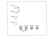
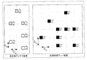
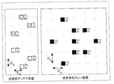
- FIG. 1A shows a transmitting array antenna including four transmitting antennas (Tx # 1 to Tx # 4) arranged in the vertical direction (vertical direction in FIG. 1A) and a horizontal direction (horizontal direction in FIG. 1A). ) Indicates a receiving array antenna including four receiving antennas (Rx # 1 to Rx # 4).
- the transmitting antennas are arranged at equal intervals (d V ) in the vertical direction
- the receiving antennas are arranged at equal intervals (d H ) in the horizontal direction (see, for example, Non-Patent Document 4).
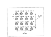
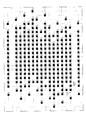
- FIG. 1B shows a virtual reception array including a transmit / receive array antenna with the antenna arrangement shown in FIG. 1A.
- the virtual reception array shown in FIG. 1B is composed of 16 element virtual reception antennas (VA # 1 to VA # 16) in which four antennas in the horizontal direction and four antennas in the vertical direction are arranged in a rectangular shape.
- the element spacings in the horizontal direction and the vertical direction of the virtual reception array are d H and d V , respectively.
- ⁇ indicates the wavelength of the radar carrier wave.
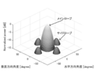
- the main beam (main lobe) is formed in the horizontal 0 ° and vertical 0 ° directions.
- the narrower the beam width of the main beam the better the angle separation performance for a plurality of targets.
- the beam width having a power value of 3 dB is about 13 °.
- side lobes are generated around the main beam.
- the side lobe becomes a cause of false detection as a virtual image. Therefore, the lower the peak level of the side lobe, the lower the probability of false detection as a virtual image in the radar device.
- the power ratio peak sidelobe level ratio (PSLR: Peak Sidelobe Level Ratio)
- PSLR Peak Sidelobe Level Ratio
- the antenna gain can be improved by narrowing the directivity (beam width) of the antenna.
- the directivity of the antenna becomes narrower as the opening surface of the antenna is widened, for example. Therefore, in order to narrow the directivity of the antenna, the antenna size becomes large.
- a sub-array antenna composed of a plurality of antenna elements arranged in the vertical direction is used in order to narrow the directivity in the vertical direction (for example, non-patented). See Document 3).
- the antenna gain in the vertical direction can be improved, and the reflected wave in an unnecessary direction such as the road surface can be reduced.
- the sub-array antenna is used for the antenna element constituting the transmitting array antenna or the receiving array antenna, it is difficult to arrange the element spacing of the array antenna at a spacing narrower than the size of the sub-array antenna.
- the size of the sub-array antenna can be one wavelength or more.
- the sub-array antenna in a vertical direction in the MIMO radar shown in FIG. 1A will broaden the vertical element spacing d V than one wavelength.
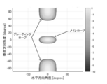
- the main beam (main lobe) is oriented in the horizontal 0 ° and vertical 0 ° directions, for example, in the vertical direction around the main beam as compared with the side lobes of FIGS. 2A and 2B.
- the ratio of the peak level of the grating lobe to the peak level of the main lobe is 0 dB.
- the radar device in the radar device, as the antenna size in the vertical direction increases, the element spacing in the vertical direction increases, so that a grating lobe is likely to occur at an angle relatively close to the main beam. Therefore, when the detection angle range assumed by the radar device is wider than the angle at which the grating lobe is generated, the radar device mistakenly targets the false peak caused by the grating lobe within the detection angle range. The probability of detection as a mark) increases, and the detection performance of the radar device may deteriorate.
- the antenna size (or element size) in the vertical or horizontal direction is one wavelength or more. However, it suppresses the occurrence of grating lobes and makes it possible to improve the angular resolution in the vertical or horizontal direction.
- the radar device a configuration will be described in which different transmission signals code-division-multiplexed are transmitted from a plurality of transmission antennas in the transmission branch, and each transmission signal is separated and received in the reception branch.
- the configuration of the radar device is not limited to this, and in the transmission branch, different transmission signals frequency-division-multiplexed are transmitted from a plurality of transmission antennas, and in the reception branch, each transmission signal is separated and received. It may be configured.
- the radar device may be configured to transmit time-division-multiplexed transmission signals from a plurality of transmission antennas at the transmission branch and perform reception processing at the reception branch.
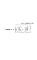
- FIG. 4 is a block diagram showing the configuration of the radar device 10 according to the present embodiment.
- the radar device 10 has a radar transmission unit (transmission branch) 100, a radar reception unit (reception branch) 200, and a reference signal generation unit 300.
- the radar transmission unit 100 generates a high frequency (radio frequency) radar signal (radar transmission signal) based on the reference signal received from the reference signal generation unit 300. Then, the radar transmission unit 100 transmits a radar transmission signal at a predetermined transmission cycle by using a transmission array antenna composed of a plurality of transmission antennas 106-1 to 106-Nt.
- the radar receiving unit 200 receives the reflected wave signal reflected by the radar transmission signal on the target (not shown) by using a receiving array antenna including a plurality of receiving antennas 202-1 to 202-Na.
- the radar receiving unit 200 performs the following processing operation using the reference signal received from the reference signal generating unit 300 to perform processing synchronized with the radar transmitting unit 100. That is, the radar receiving unit 200 processes the reflected wave signal received by each receiving antenna 202, and performs at least one process of detecting the presence or absence of a target and estimating the direction.
- the target is an object to be detected by the radar device 10, and includes, for example, a vehicle (including four wheels and two wheels) or a person.
- the reference signal generation unit 300 is connected to each of the radar transmission unit 100 and the radar reception unit 200.
- the reference signal generation unit 300 supplies a reference signal as a reference signal to the radar transmission unit 100 and the radar reception unit 200, and synchronizes the processing of the radar transmission unit 100 and the radar reception unit 200.
- the radar transmission unit 100 includes radar transmission signal generation units 101-1 to 101-Nt, transmission radio units 105-1 to 105-Nt, and transmission antennas 106-1 to 106-Nt. That is, the radar transmission unit 100 has Nt transmission antennas 106, and each transmission antenna 106 is connected to an individual radar transmission signal generation unit 101 and a transmission radio unit 105, respectively.
- the radar transmission signal generation unit 101 generates a timing clock obtained by multiplying the reference signal received from the reference signal generation unit 300 by a predetermined number of times, and generates a radar transmission signal based on the generated timing clock. Then, the radar transmission signal generation unit 101 repeatedly outputs the radar transmission signal in a predetermined radar transmission cycle (Tr).
- j represents an imaginary unit
- k represents a discrete time
- M represents the ordinal number of the radar transmission cycle.
- Each radar transmission signal generation unit 101 includes a code generation unit 102, a modulation unit 103, and an LPF (Low Pass Filter) 104.
- LPF Low Pass Filter
- a code having a low correlation or no correlation with each other is used.
- the code sequence include a Walsh-Hadamard code, an M-sequence code, and a Gold code.
- the modulation unit 103 performs pulse modulation (amplitude modulation, ASK (Amplitude Shift Keying), pulse shift keying) or phase modulation (Phase) with respect to the code sequence (for example, the code a (z) n ) output from the code generation unit 102. Shift Keying) is performed, and the modulated signal is output to the LPF104.
- pulse modulation amplitude modulation, ASK (Amplitude Shift Keying), pulse shift keying
- Phase modulation Phase modulation
- the LPF 104 outputs a signal component below a predetermined limiting band among the modulated signals output from the modulation unit 103 to the transmission radio unit 105 as a baseband radar transmission signal.
- a carrier frequency A radar transmission signal in the Radio Frequency (RF) band is generated, amplified to a predetermined transmission power P [dB] by a transmission amplifier, and output to the z-th transmission antenna 106.
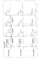
- FIG. 5 shows radar transmission signals transmitted from Nt transmission antennas 106 of the radar transmission unit 100.
- a pulse code sequence having a code length L is included in the code transmission section Tw.
- Tr a pulse code sequence is transmitted during the code transmission section Tw, and the remaining section (Tr-Tw) is a non-signal section.
- Nr No samples per one pulse code
- the sampling rate in the modulation unit 103 is (No ⁇ L) / Tw.
- the non-signal section (Tr-Tw) contains Nu samples.
- the radar transmission unit 100 may include the radar transmission signal generation unit 101a shown in FIG. 6 instead of the radar transmission signal generation unit 101.
- the radar transmission signal generation unit 101a does not have the code generation unit 102, the modulation unit 103, and the LPF 104 shown in FIG. 4, but instead includes the code storage unit 111 and the DA conversion unit 112.
- the code storage unit 111 stores in advance the code sequence generated by the code generation unit 102 (FIG. 4), and sequentially reads out the stored code sequence in a cyclic manner.
- the DA conversion unit 112 converts the code sequence (digital signal) output from the code storage unit 111 into an analog signal (baseband signal).
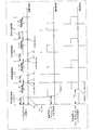
- the radar receiving unit 200 includes Na receiving antennas 202 and constitutes an array antenna. Further, the radar receiving unit 200 includes Na antenna system processing units 211-1 to 201-Na and a direction estimation unit 214.
- Each receiving antenna 202 receives a reflected wave signal which is a radar transmission signal reflected by a target (object), and outputs the received reflected wave signal to the corresponding antenna system processing unit 201 as a receiving signal.
- Each antenna system processing unit 201 has a receiving radio unit 203 and a signal processing unit 207.
- the receiving radio unit 203 includes an amplifier 204, a frequency converter 205, and an orthogonal detector 206.
- the receiving radio unit 203 generates a timing clock obtained by multiplying the reference signal output from the reference signal generation unit 300 by a predetermined number, and operates based on the generated timing clock.
- the amplifier 204 amplifies the received signal output from the receiving antenna 202 to a predetermined level
- the frequency converter 205 frequency-converts the received signal in the high frequency band into the base band band
- the orthogonal detector 206 frequency-converts the received signal. , Converts the baseband band received signal into a baseband band received signal including the I signal and the Q signal.
- the signal processing unit 207 has AD conversion units 208 and 209 and separation units 210-1 to 210-Nt.
- the I signal is input from the orthogonal detector 206 to the AD conversion unit 208, and the Q signal is input from the orthogonal detector 206 to the AD conversion unit 209.
- the AD conversion unit 208 converts the I signal into digital data by sampling the baseband signal including the I signal at discrete times.
- the AD conversion unit 209 converts the Q signal into digital data by sampling the baseband signal including the Q signal at discrete times.
- j is an imaginary unit.
- the signal processing unit 207 includes Nt separation units 210 equal to the number of systems corresponding to the number of transmitting antennas 106.
- Each separation unit 210 has a correlation calculation unit 211, an addition unit 212, and a Doppler frequency analysis unit 213.
- the range ie, the range of k
- the radar device 10 does not perform processing by the correlation calculation unit 211 during the wraparound period (at least a period of less than ⁇ 1). Therefore, it is possible to perform measurement without the influence of wraparound.
- the measurement range (range of k) is limited, the measurement range (range of k) is similarly limited for the processing of the addition unit 212, the Doppler frequency analysis unit 213, and the direction estimation unit 214 described below. The processing that has been performed may be applied. As a result, the amount of processing in each component can be reduced, and the power consumption in the radar receiving unit 200 can be reduced.
- the addition unit 212 uses the correlation calculation value AC (z) (k, M) output from the correlation calculation unit 211 for each discrete time k of the Mth radar transmission cycle Tr for a predetermined number of times (Np times).
- the correlation calculation values AC (z) (k, M) are added (coherent integration) over the period (Tr ⁇ Np) of the radar transmission cycle Tr.
- the addition (coherent integration) process of the addition number Np over the period (Tr ⁇ Np) is expressed by the following equation.
- CI (z) (k, m) represents the addition value of the correlation calculation value (hereinafter referred to as the correlation addition value)
- Np is an integer value of 1 or more
- m is the number of additions Np in the addition unit 212. Is an integer of 1 or more indicating the order of the number of additions when is used as one unit.
- z 1, ..., Nt.
- the addition unit 212 performs Np additions using the output of the correlation calculation unit 211 obtained in units of the radar transmission cycle Tr as one unit. That is, the addition unit 212 aligns the timing of the discrete time k with the correlation calculation values AC (z) (k, Np (m-1) +1) to AC (z) (k, Np ⁇ m) as one unit.
- the correlation value CI (z) (k, m) added by the above is calculated for each discrete time k.
- the addition unit 212 can improve the SNR (Signal to Noise Ratio) of the reflected wave signal in a range in which the reflected wave signal from the target has a high correlation due to the effect of adding the correlation calculation value over Np times. Therefore, the radar receiving unit 200 can improve the measurement performance regarding the estimation of the arrival distance of the target.
- the number of additions Np is preferably set based on the assumed maximum moving speed of the target to be measured. This is because the larger the assumed maximum velocity of the target, the larger the fluctuation amount of the Doppler frequency included in the reflected wave from the target. Therefore, since the time period having a high correlation is shortened, the number of additions Np becomes a small value, and the gain improvement effect due to the addition by the addition unit 212 becomes small.
- FT_CI (z) Nant (k, fs, w) is the w-th output in the Doppler frequency analysis unit 213, and the Doppler frequency fs ⁇ in the discrete time k in the Nant-th antenna system processing unit 201.
- the coherent integration result is shown.
- Nant 1 to Na
- w is an integer of 1 or more.
- ⁇ is a phase rotation unit.
- each antenna system processing unit 201 can perform coherent integration results corresponding to 2 Nf Doppler frequency components for each discrete time k, FT_CI (z) Nant (k, -Nf + 1, w), ..., FT_CI ( z) Nant (k, Nf-1, w) is obtained every multiple times Np ⁇ Nc period (Tr ⁇ Np ⁇ Nc) of Tr between radar transmission cycles.
- j is an imaginary unit
- z 1, ..., Nt.
- DFT Discrete Fourier Transform
- the Doppler frequency analysis unit 213 can apply a fast Fourier transform (FFT) process, and can reduce the amount of arithmetic processing.
- FFT fast Fourier transform
- the Doppler frequency analysis unit 213 may perform a process of sequentially calculating the product-sum operation shown in the above equation (3) instead of the FFT process. That is, the Doppler frequency analysis unit 213 fs with respect to CI (z) (k, Nc (w-1) + q + 1), which is the output of Nc of the addition unit 212 obtained for each discrete time k.
- q 0 to Nc-1.
- (k, fs, w),..., FT_CI (z) Na (k, fs, w) is expressed as a virtual reception array correlation vector h (k, fs, w) as shown in the following equation.
- the virtual reception array correlation vector h (k, fs, w) includes Nt ⁇ Na elements which are the products of the number of transmitting antennas Nt and the number of receiving antennas Na.
- the virtual reception array correlation vector h (k, fs, w) is used for a description of a process for estimating the direction of the reflected wave signal from the target based on the phase difference between the receiving antennas 202, which will be described later.
- the direction estimation unit 214 has an array correction value h_cal with respect to the virtual reception array correlation vector h (k, fs, w) of the w-th Doppler frequency analysis unit 213 output from the antenna system processing units 211-1 to 201-Na.
- the virtual reception array correlation vector h _after_cal (k, fs, w) in which the phase deviation and the amplitude deviation between the antenna system processing units 201 are corrected is calculated.
- the virtual reception array correlation vector h _after_cal (k, fs, w) corrected for the deviation between antennas is a column vector consisting of Na ⁇ Nr elements.
- each element of the virtual reception array correlation vector h _after_cal (k, fs, w) is expressed as h 1 (k, fs, w),..., h Na ⁇ Nr (k, fs, w) and the direction. Used to explain the estimation process.
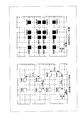
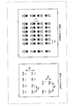
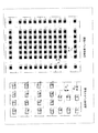
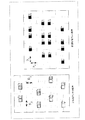
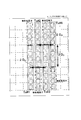
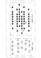
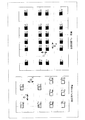
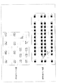
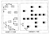
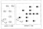
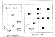
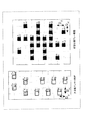
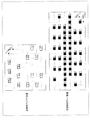
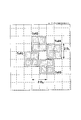
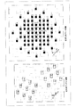
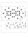
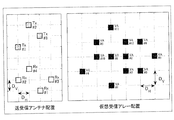
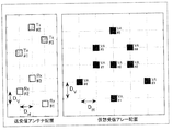
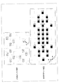
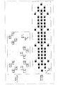
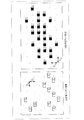
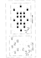
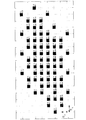
- FIG. 8 shows an arrangement example of the transmitting antenna 106 and the receiving antenna 202 according to the basic arrangement 1 and an arrangement example of the virtual reception array.
- the horizontal direction e.g., horizontal direction in FIG. 8
- spacing D H, and the spacing D V in the vertical direction e.g., vertical direction in FIG. 8
- the distance D H, and the distance D V may be different.
- the number of Na 4 (Rx # 1, Rx # 2, Rx # 3 and Rx # 4).
- the transmitting array antennas shown in FIG. 8 are a "first transmitting antenna group" (Tx # 2, Tx # 4 in FIG. 8) and a “second transmitting antenna group” (Tx # 1, Tx in FIG. 8). It consists of # 3).
- Each transmitting antenna group includes two transmitting antenna elements that are in the same position in the vertical direction and have an antenna spacing of 2D H in the horizontal direction (horizontal direction in FIG. 8). Further, the distance between the "first transmitting antenna group” and the "second transmitting antenna group” in the vertical direction (vertical direction in FIG. 8) is, for example, 3D V.
- the receiving array antennas shown in FIG. 8 are the "first receiving antenna group” (Rx # 2, Rx # 4 in FIG. 8) and the “second receiving antenna group” (Rx # 1 in FIG. 8). , Rx # 3).
- Each receiving antenna group includes two receiving antenna elements that are in the same position in the vertical direction and have an antenna spacing of 3D H in the horizontal direction. Further, the vertical distance between the "first receiving antenna group” and the “second receiving antenna group” is, for example, 2D V.
- the difference between the antenna spacing 2D H (interval of an integral multiple of D H ) in the transmitting antenna group and the antenna spacing 3D H (interval of an integral multiple of D H ) in the receiving antenna group is D H. is there. Further, in FIG. 8, an interval a plurality of reception antenna group and spacing a plurality of transmit antenna groups are disposed 3D V (integral multiple of the spacing D V) is arranged 2D V (integral multiple of the spacing D V) the difference is a D V.
- the virtual reception array is arranged by the following equation from the position of the transmitting antenna constituting the transmitting array antenna (position of the feeding point) and the position of the receiving antenna constituting the receiving array antenna (position of the feeding point). Can be expressed as
- mod (x, y) is an operator that calculates the remainder (modulo operation) after division, and returns the remainder when x is divided by y.
- ceil (x) is an operator that returns the value rounded to the nearest integer greater than or equal to x.
- VA # 1 is expressed as the position reference (0,0) of the virtual reception array.
- the position coordinates of the transmit antenna 106 constituting the transmit array antenna are based on the position coordinates of the transmit antenna Tx # 1 (X T_ # 1 , Y T_ # 1 ) and the position coordinates of the transmit antenna Tx # 2 (X T_ # 2).
- the position coordinates of the receiving antenna 202 constituting the receiving array antenna are the position coordinates (X) of the receiving antenna Rx # 2 with reference to the position coordinates of the receiving antenna Rx # 1 (X R_ # 1 , Y R_ # 1 ).
- the position coordinates of the virtual receiving array VA # 1 to VA # 16 (X V_ # 1 , Y V_ # 1 ) to (X V_ # 16 , Y V_ #) 16 ) are as follows.
- each virtual reception array element is arranged at a different position without overlapping. Therefore, since the aperture length of the virtual reception array can be expanded, the main lobe is narrowed and the angular resolution can be improved.
- the virtual array elements VA # 4, VA # 7, VA # 10 and VA # 13 located near the center of the virtual receiving array, D V in the horizontal direction D H interval, vertically They are closely arranged at intervals.
- D H 0.5 [lambda horizontally spacing
- D V 0.5 [lambda intervals in the vertical direction.
- the positional relationship between the transmitting array antenna and the receiving array antenna is not limited to the arrangement shown in FIG. 8, and can be set arbitrarily. The same applies to the other arrangement configurations described below.
- the arrangement in the horizontal direction and the vertical direction in the arrangement of the transmission array antenna and the reception array antenna shown in FIG. 8 is the same as the arrangement in the vertical direction and the horizontal direction (for example, the arrangement in which the arrangement in FIG. 8 is rotated by 90 degrees). The effect is obtained. The same applies to the other arrangement configurations described below.
- the arrangement of the transmitting array antenna and the arrangement of the receiving array antenna may be interchanged.
- the arrangement of the receiving array antenna shown in FIG. 8 may be used as the arrangement of the transmitting array antenna
- the arrangement of the transmitting array antenna shown in FIG. 8 may be used as the arrangement of the receiving array antenna.
- the arrangement of the virtual reception array is the same, so that the same effect can be obtained. The same applies to the other arrangement configurations described below.
- the distance between the antenna elements is one of 2D H , 3D H , 2D V, and 3D V.
- the spacing 3D V between the transmitting antenna groups, the antenna spacing 3D H within the receiving antenna group, the antenna spacing 2D H within the transmitting antenna group, and the spacing 2D V between the receiving antenna groups are radar transmissions.
- the interval is longer than one wavelength of the signal (for example, radar carrier wave). Therefore, in FIG. 8, the element sizes of the transmitting antenna 106 and the receiving antenna 202 in the horizontal and vertical directions can be designed to be about 1 ⁇ or more.
- an antenna using four elements in which two plane patch antennas are arranged vertically and horizontally in a sub-array is used as a sub-array, and at least one of the transmitting array antenna and the receiving array antenna shown in FIG. It can be applied to the element.
- the antenna width W ANT ⁇ 2D H and the antenna height H ANT ⁇ 2D V are used as a sub-array, and at least one of the transmitting array antenna and the receiving array antenna shown in FIG. It can be applied to the element.
- the antenna width W ANT ⁇ 2D H and the antenna height H ANT ⁇ 2D V is used as a sub-array, and at least one of the transmitting array antenna and the receiving array antenna shown in FIG. It can be applied to the element.
- the antenna width W ANT ⁇ 2D H and the antenna height H ANT ⁇ 2D V are used as a sub-array, and at least one of the transmitting array antenna and the receiving array antenna shown in FIG. It can be applied to the element.
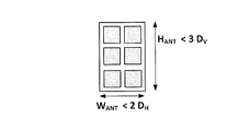
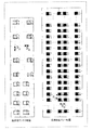
- the vertical antenna spacing of the transmitting array antennas is 3D V , which is wider than the horizontal antenna spacing of 2D H. Therefore, for example, an antenna using a flat patch antenna as shown in FIG. 9B with three elements arranged vertically and six elements arranged horizontally with two elements as a sub-array can be applied to each antenna element of the transmitting array antenna shown in FIG. ..
- the antenna width W ANT ⁇ 2D H and the antenna height H ANT ⁇ 3D V the antenna width W ANT ⁇ 2D H and the antenna height H ANT ⁇ 3D V.
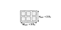
- the horizontal antenna spacing of the receiving array antenna is 3D H , which is wider than the vertical antenna spacing of 2D V. Therefore, for example, an antenna using as a sub-array with 6 elements in which two plane patch antennas are arranged vertically and three elements are arranged horizontally as shown in FIG. 9C can be applied to each antenna element of the receiving array antenna shown in FIG. ..
- the antenna width W ANT ⁇ 3D H and the antenna height H ANT ⁇ 2D V the antenna width W ANT ⁇ 3D H and the antenna height H ANT ⁇ 2D V.
- the directivity gain of the antenna can be improved by using an antenna having a sub-array configuration as shown in FIGS. 9A, 9B or 9C, and the detection performance (for example, detection distance) in the radar device 10 can be improved.
- the configuration of the sub-array applied to the antenna element shown in FIG. 8 is not limited to the configuration shown in FIGS. 9A, 9B and 9C, and the position shown in FIG. 8 is the phase center of the antenna element (in other words, the antenna system). Any sub-array configuration that can be arranged as
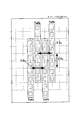
- FIG. 10 shows an example in which the sub-array shown in FIG. 9B is applied to each antenna element of the transmitting array antenna shown in FIG.
- the transmitting array antenna is composed of antenna elements having a sub-array configuration of a vertical size of 3D V and a horizontal size of 2D H.
- the direction estimation unit 214 uses the received signal of the virtual reception array (see, for example, FIG. 8) obtained from the above-described transmission / reception antenna arrangement (see, for example, FIG. 8) to perform the horizontal and vertical direction estimation processing. Is performed as follows.
- the element number (VA # number) of the virtual reception array corresponds to the element number of the column vector of the virtual reception array correlation vector h _after_cal (k, fs, w) in which the deviation between the antennas shown in the equation (6) is corrected. ..
- VA # 1 shown in FIG. 8 corresponds to the first element h 1 (k, fs, w) of the column vector element of h _after_cal (k, fs, w).
- the direction estimation unit 214 changes the azimuth direction ⁇ and the elevation angle direction ⁇ in the direction estimation evaluation function values P ( ⁇ , ⁇ , k, fs, w) within a predetermined angle range. Calculate the spatial profile as.
- the direction estimation unit 214 extracts a predetermined number of the calculated maximum peaks of the spatial profile in descending order, and outputs the azimuth direction and elevation angle direction of the maximum peaks as the arrival direction estimated values.
- evaluation function value P ( ⁇ , ⁇ , k, fs, w) depending on the arrival direction estimation algorithm.
- an estimation method using an array antenna disclosed in a reference non-patent document may be used.
- the beamformer method can be expressed as the following equation.
- Other methods such as Capon and MUSIC can be applied as well.
- a ( ⁇ u , ⁇ v ) indicates the direction vector of the virtual reception array with respect to the incoming wave in the azimuth direction ⁇ and the elevation angle direction ⁇ .
- the direction estimation unit 214 outputs the calculated arrival direction estimation value, the discrete time k at the time of calculating the arrival direction estimation value, and the Doppler frequency fs ⁇ as the radar positioning result.
- the azimuth direction ⁇ u is a vector obtained by changing the azimuth range in which the arrival direction is estimated by a predetermined azimuth interval ⁇ 1 .
- ⁇ u is set as follows.
- floor (x) is a function that returns the maximum integer value that does not exceed the real number x.
- ⁇ v is obtained by changing the range of the elevation angle for estimating the arrival direction with a predetermined azimuth interval ⁇ 2 .
- the direction vector a ( ⁇ u , ⁇ v ) of the virtual reception array is calculated in advance based on the virtual reception array arrangements VA # 1, ..., VA # (Nt ⁇ Na).
- the direction vector a ( ⁇ u , ⁇ v ) is a (Nt ⁇ Na) next column vector whose elements are the complex response of the virtual reception array when the radar reflected wave arrives from the azimuth direction ⁇ and the elevation angle direction ⁇ . Is.
- the complex response a ( ⁇ u , ⁇ v ) of the virtual reception array represents the phase difference calculated geometrically and optically at the element spacing between the antennas.
- time information k may be converted into distance information and output.
- R (k) the distance information R (k)
- Tw represents the code transmission section
- L represents the pulse code length
- C 0 represents the speed of light.
- the Doppler frequency information (fs ⁇ ) may be converted into a relative velocity component and output.
- fs ⁇ the Doppler frequency information (fs ⁇ ) may be converted into a relative velocity component and output.
- vd the relative velocity component
- ⁇ is the wavelength of the carrier frequency of the RF signal output from the transmission radio unit 105.
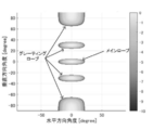
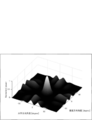
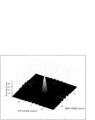
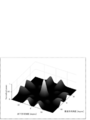
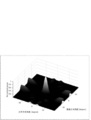
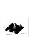
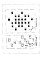
- FIGS. 11A and 11B show an example of the direction estimation result when the beamformer method is used for the arrival direction estimation algorithm of the direction estimation unit 214.
- the output of the arrival direction estimation evaluation function value in the horizontal ⁇ 90 degree range and the vertical ⁇ 90 degree range when the target true value is 0 degrees horizontally and 0 degrees vertically is plotted. There is.
- the directivity of each antenna is calculated as omnidirectional.
- grating lobes are generated in the horizontal direction and the vertical direction in directions other than the horizontal 0 degree and the vertical 0 degree of the target true value.
- FIG. 11A it can be confirmed that the grating lobe is reduced in the directions other than the horizontal 0 degree and the vertical 0 degree of the target true value.
- the ratio of the peak power value of the main lobe in the horizontal 0 degree and vertical 0 degree directions to the peak power value of the highest side lobe excluding the main lobe in directions other than horizontal 0 degree and vertical 0 degree ( PSLR) is about 0.44.
- the antenna spacing can be arranged so as to include the element spacing of about 0.5 ⁇ , and the grating lobe can be reduced. Further, for example, as shown in FIG. 8, since the virtual array elements of the virtual reception array are arranged without overlapping, the aperture length of the virtual reception array can be expanded and the angular resolution can be improved.
- an antenna having a sub-array configuration having an element size of at least 1 ⁇ in the vertical and horizontal directions can be used as the antenna element used for the transmitting antenna 106 and the receiving antenna 202. Therefore, the directivity gain of the antenna can be improved, and the detection performance (for example, the detection distance) of the radar device 10 can be improved.
- the MIMO array arrangement is not limited to the example shown in FIG.
- the arrangement in which the horizontal direction and the vertical direction of the antenna arrangement shown in FIG. 8 are interchanged may be used.
- the virtual reception array arrangement can be obtained by exchanging the horizontal direction and the vertical direction of the arrangement shown in FIG.
- the angle separation performance in which the horizontal direction and the vertical direction of FIGS. 8 and 8 are exchanged can be obtained.
- an arrangement in which the horizontal direction and the vertical direction are interchanged may be used.
- the basic arrangement 1 for example, FIG. 8
- the number of transmitting antennas Nt and the number of receiving antennas Na are not limited to these numbers.
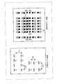
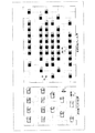
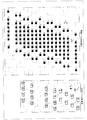
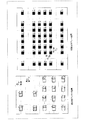
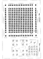
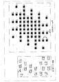
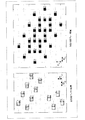
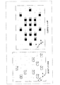
- the transmission array antenna is composed of, for example, a first transmitting antenna group and a second transmitting antenna group having a vertical interval of 3D V , as in the basic arrangement 1. .. Further, each transmitting antenna group includes a plurality of transmitting antenna elements having the same position in the vertical direction and an antenna spacing of 2D H in the horizontal direction, as in the basic arrangement 1.
- the receiving array antenna is composed of, for example, a plurality of receiving antenna groups having a vertical interval of 2D V , as in the basic arrangement 1.
- each receiving antenna group includes a plurality of receiving antenna elements having the same position in the vertical direction and an antenna spacing of 3D H in the horizontal direction.
- the vertical distance between the transmitting antenna groups (here, 3D V ) and the horizontal distance between the antennas in each receiving antenna group (here, here). 3D H ) is the same. Furthermore, (in this case, 2D H) horizontal antenna spacing within each transmit antenna group and the vertical spacing between the receiving antenna groups (here, 2D H) and are identical.
- N TxGroup the number of transmitting antenna groups
- N TxGroup_ANT the number of transmitting antennas included in each transmitting antenna group
- N RxGroup_ANT the number of receive antenna group
- N RxGroup_ANT the number of transmission antennas included in each reception antenna group
- the arrangement in which the number of antennas of the MIMO array is increased is possible according to the values of N TxGroup_ANT and N RxGroup .
- the horizontal and vertical element size of the transmit antenna 106 and receive antenna 202 1 [lambda It can be designed to a size larger than the degree.
- the virtual array elements are arranged at different positions without overlapping, so that the aperture length of the virtual reception array can be expanded and the angular resolution is improved. it can.
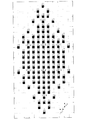
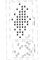
- the virtual array elements located near the center of each virtual reception array shown in FIGS. 12, 13 and 14 can be densely arranged at D H and DV intervals. Further, D H, the number of virtual array elements that are densely arranged in D V interval is increased depending on N TxGroup_ANT and N RxGroup.
- the virtual reception array in the horizontal direction (N TxGroup_ANT ⁇ N RxGroup_ANT) -2 virtual array elements is aligned at D H intervals, in the vertical direction (N RxGroup ⁇ N TxGroup) -2 virtual array elements D V interval Line up at.
- the effect of reducing the grating lobe and side lobe can be improved.
- N TxGroup_ANT and N RxGroup_ANT are larger, the number of virtual array elements arranged in the horizontal direction increases, so that the aperture length of the virtual reception array in the horizontal direction can be expanded and the angular resolution in the horizontal direction can be improved.
- N RxGroup and N RxGroup are larger, the number of virtual array elements arranged in the vertical direction increases, so that the aperture length of the virtual reception array in the vertical direction can be expanded and the angular resolution in the vertical direction can be improved.
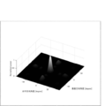
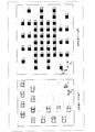
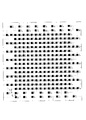
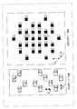
- the directivity of each antenna is calculated as omnidirectional.
- FIG. 15 plots the output of the arrival direction estimation evaluation function value in the horizontal ⁇ 90 degree range and the vertical ⁇ 90 degree range when the target true value is 0 degrees horizontally and 0 degrees vertically.
- the grating lobe is reduced in directions other than the horizontal 0 degree and the vertical 0 degree of the target true value, as compared with, for example, FIG. 11A.
- the ratio (PSLR) of the peak power value of the highest side lobe excluding the main lobe to the peak power value of the main lobe in the horizontal 0 degree and vertical 0 degree directions is about 0.22.
- the vertical antenna spacing of the transmitting antenna group may be set to a constant value (for example, 3D V ), but depending on the number of receiving antenna groups N RxGroup , the virtual receiving array arrangement is performed by the virtual array element. It can be an overlapping arrangement.
- the even-numbered antenna spacing of the transmitting antenna group in the vertical direction has the following spacing D TxGroupV. May be used.
- the distance between the three transmitting antenna groups is ⁇ 3D V , D TxGroup V ⁇ .
- the intervals between the four transmitting antenna groups are ⁇ 3D V , D TxGroupV , 3D V ⁇ .
- the number of transmitting antenna groups N RxGroup_ANT 5 the intervals between the five transmitting antenna groups are ⁇ 3D V , D TxGroupV , 3D V , D TxGroup V ⁇ .
- D TxGroupV 3D V in equation (11).
- D TxGroupV 5D V in equation (11).
- D TxGroup V may have a value larger than the value of equation (11) if an arrangement having unequal intervals (for example, an interval larger than D H and DV ) may be included near the center of the virtual reception array. Good.
- the horizontal antenna spacing of the receiving antenna group may be set to a constant value (for example, 3D H ), but the virtual receiving array arrangement depends on the number of transmitting antennas N TxGroup_ANT included in the transmitting antenna group. Can be an arrangement in which virtual array elements overlap.
- the following antenna intervals are set in the even-numbered antenna intervals of the horizontal antenna intervals of the receiving antennas included in the receiving antenna group.
- Such intervals D Rx Ant H may be used.
- N TxGroup_ANT 3D H
- D RxAntH 3D H
- D RxAntH 5D H.
- the antenna spacing of the three receiving antennas is ⁇ 3D H , D RxAnt H ⁇ .
- the antenna spacing of the four receiving antennas is ⁇ 3D H , D RxAntH , 3D H ⁇ .
- the antenna spacing of the five receiving antennas is ⁇ 3D H , D RxAntH , 3D H , D RxAntH ⁇ .
- D RxAntH 3D H in equation (12).
- D RxAntH 5D H in equation (12).
- receive antenna arrangement shown in FIGS. 16 to 19 (e.g., MIMO array arrangement) in, by and 0.5 ⁇ about the D H and D V, the horizontal and vertical elements of the transmit antenna 106 and receive antenna 202
- the size can be designed to be about 1 ⁇ or more.
- the aperture length of the virtual reception array can be expanded and the angular resolution can be improved.
- virtual array elements located near the center of the virtual reception array shown in FIGS. 16 to 19 can be densely arranged at D H and DV intervals.
- D H the number of virtual array elements that are densely arranged in D V interval, N TxGroup, N TxGroup_ANT, increases depending on the N RxGroup and N RxGroup_ANT.
- the virtual reception array in the horizontal direction (N TxGroup_ANT ⁇ N RxGroup_ANT) -2 virtual array elements is aligned at D H intervals, in the vertical direction (N RxGroup ⁇ N TxGroup) -2 virtual array elements D V interval Line up at.
- the effect of reducing the grating lobe and side lobe can be improved.
- N TxGroup_ANT and N RxGroup_ANT are larger, the number of virtual array elements arranged in the horizontal direction increases, so that the aperture length of the virtual reception array in the horizontal direction can be expanded and the angular resolution in the horizontal direction can be improved.
- the number of virtual array elements arranged in the vertical direction increases, so that the aperture length of the virtual reception array in the vertical direction can be expanded and the angular resolution in the vertical direction can be improved.
- D TxGroupV 5D H next to Formula (11)
- the D RxAntH 5D H of formula (12)
- each transmitting antenna included in the first transmitting antenna group and the second transmitting antenna group may be arranged by shifting the horizontal position by D H (in other words, shifting). ..
- the direction of D H shift in the horizontal direction may be either the right direction or the left direction for each transmitting antenna included in the second transmitting antenna group with respect to each transmitting antenna included in the first transmitting antenna group.
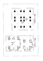
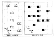
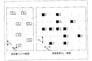
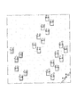
- FIG. 21 shows each transmitting antenna (for example, Tx # 2, Tx # 4) included in the first transmitting antenna group and each transmitting antenna (for example, Tx # 2, Tx # 4) included in the second transmitting antenna group in the transmitting array antenna.
- Tx # 1 and Tx # 3) are shifted to the right by D H , and an example of arranging the transmitting antenna 106 and the receiving antenna 202 and an example of arranging the virtual receiving array are shown.
- each receiving antenna included in the first receiving antenna group and the second receiving antenna group may be arranged with the horizontal position shifted by D H.
- the direction of D H shift in the horizontal direction may be either the right direction or the left direction of each receiving antenna included in the second receiving antenna group with respect to each receiving antenna included in the first receiving antenna group.
- FIG. 22 shows each receiving antenna (for example, Rx # 2, Rx # 4) included in the first receiving antenna group and each receiving antenna (for example, Rx # 2, Rx # 4) included in the second receiving antenna group in the receiving array antenna. , Rx # 1 and Rx # 3) are shifted to the right by D H , and an example of arranging the transmitting antenna 106 and the receiving antenna 202 and an example of arranging the virtual receiving array are shown.
- the arrangement method 1-3C is a method in which the arrangement method 1-3A and the arrangement method 1-3B are combined.
- the transmitting antennas are arranged with a horizontal position shifted by D H between the first transmitting antenna group and the second transmitting antenna group.
- the receiving antennas are arranged with the horizontal position shifted by D H between the first receiving antenna group and the second receiving antenna group.
- the direction of shifting in a horizontal direction D H is, for example, for each transmit antenna included in the first transmission antenna group, each transmit antenna rightward or leftward any included in the second transmission antenna group It may be in the direction. Further, in the horizontal D H shift direction, for example, for each receiving antenna included in the first receiving antenna group, each receiving antenna included in the second receiving antenna group is either rightward or leftward. It may be in the direction.
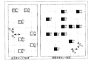
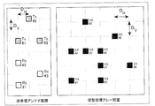
- FIG. 23 shows an arrangement example of the transmitting antenna 106 and the receiving antenna 202 according to the arrangement method 1-3C, and an arrangement example of the virtual reception array.
- each transmitting antenna for example, Tx # 2, Tx # 4 included in the first transmitting antenna group is compared with each transmitting antenna (for example, Tx # 2, Tx # 4) included in the second transmitting antenna group.
- Tx # 1, Tx # 3) are arranged with a D H shift to the left.
- each receiving antenna included in the second receiving antenna group is used for each receiving antenna (for example, Rx # 2, Rx # 4) included in the first receiving antenna group. (For example, Rx # 1 and Rx # 3) are arranged with a D H shift to the left.
- FIG. 24 shows an arrangement example of the transmitting antenna 106 and the receiving antenna 202 according to the arrangement method 1-3C, and an arrangement example of the virtual reception array.
- each transmitting antenna for example, Tx # 2, Tx # 4 included in the first transmitting antenna group is compared with each transmitting antenna (for example, Tx # 2, Tx # 4) included in the second transmitting antenna group.
- Tx # 1, Tx # 3) are arranged with a D H shift to the left.
- each receiving antenna included in the second receiving antenna group is used for each receiving antenna (for example, Rx # 2, Rx # 4) included in the first receiving antenna group. (For example, Rx # 1 and Rx # 3) are arranged with a D H shift to the right.
- arrangement and different direction and a direction shifting D H in the horizontal direction by the reception antenna group and the transmit antenna group (e.g., FIG. 24) as compared to, shifted D H in the horizontal direction by the reception antenna group and the transmit antenna group
- An arrangement in which the directions are the same is more preferable because the virtual reception array elements are arranged more densely near the center of the virtual reception array arrangement.
- receive antenna arrangement shown in FIGS. 21 to 24 (e.g., MIMO array arrangement) in, by and 0.5 ⁇ about the D H and D V, the horizontal and vertical elements of the transmit antenna 106 and receive antenna 202
- the size can be designed to a size of about 1 ⁇ .
- an antenna using four elements in which two plane patch antennas are arranged vertically and horizontally as shown in FIG. 9A is used for the sub-array (however, the antenna width W ANT ⁇ 2D H , the antenna height). H ANT ⁇ 2D V ) can be applied (not shown).
- the vertical spacing between the transmitting antenna groups is 3D V
- the horizontal spacing between the transmitting antennas within each transmitting antenna group is 2D H
- the transmitting array antennas are more vertical than the horizontal spacing.
- the interval is wide. Therefore, in the modified example 3 of the basic arrangement 1, for example, as shown in FIG. 9B, an antenna using 6 elements in which 3 vertical elements and 2 horizontal elements are arranged as a sub array (however, the antenna width W ANT ⁇ 2D). H , antenna height H ANT ⁇ 3D V ) can be applied.
- the horizontal positions of the transmitting antenna included in each transmitting antenna group or the receiving antenna included in each receiving antenna group are aligned with each other in the horizontal direction. different. Therefore, in the modification 3 of the basic arrangement 1, if the element size of the horizontal W ANT of the sub array is smaller than D H , the element size of the sub array in the vertical direction may be any size.
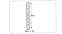
- FIG. 25A shows an example of a sub-array in which a flat patch antenna is arranged with 8 elements vertically and 1 element horizontally.
- the configuration of the sub array is not limited to the configuration shown in FIG. 25A.
- FIG. 25B shows an example in which the sub-array shown in FIG. 25A is applied to the transmitting antenna array shown in FIG. 23 or FIG. 24.
- a non-feeding element (dummy element) may be arranged as shown in FIG. 25C.
- the influence of the coupling between the antennas by the adjacent antennas can be made uniform for each antenna, and the directional characteristics of each transmitting antenna (Tx # 1 to # 4) can be made uniform.
- Tx # 1 to # 4 the influence of electrical characteristics such as antenna radiation, impedance matching, or isolation can be made uniform.
- the arrangement of the non-feeding element is not limited to FIG. 25C, and may be arranged at a position and size that do not physically interfere with each antenna.
- the directivity gain of the antenna can be improved and the detection performance (for example, the detection distance) in the radar device 10 can be improved by using the antenna having the sub-array configuration. ..
- the opening length of the virtual reception array can be expanded and the angular resolution can be improved.
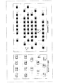
- each transmitting antenna included in the transmitting antenna group may be shifted by D H between the transmitting antenna groups with respect to the arrangement of the transmitting array antennas according to the modification 1 of the basic arrangement 1. ..
- the horizontal position of each receiving antenna included in the receiving antenna group is shifted by D H between the receiving antenna groups. It may be arranged.
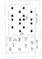
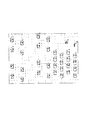
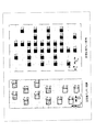
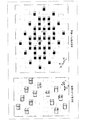
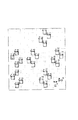
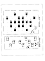
- 26 to 30 show an example of antenna arrangement in the combination of the modified example 3 and the modified example 1.
- An arrangement example of the 106 and the receiving antenna 202 and an arrangement example of the virtual reception array are shown.
- An arrangement example of the transmission antenna 106 and the reception antenna 202 and an arrangement example of the virtual reception array are shown.
- An arrangement example of the transmitting antenna 106 and the receiving antenna 202 and an arrangement example of the virtual reception array in the case where the horizontal positions of the included receiving antennas are shifted by D H are shown.
- each transmitting antenna included in the first transmitting antenna group for example, Tx # 2, Tx # 4, Tx # 6, Tx # 8), each transmitting included in the second transmitting antenna group.
- Antennas (for example, Tx # 1, Tx # 3, Tx # 5, Tx # 7) are arranged with a D H shift to the left.
- each receiving antenna included in the second receiving antenna group is used for each receiving antenna (for example, Rx # 3, Rx # 6) included in the first receiving antenna group.
- Rx # 2 and Rx # 5) are arranged with a D H shift to the left.
- each receiving antenna (for example, Rx # 1, Rx # 4) included in the third receiving antenna group is moved to the left. Arranged with a D H shift.
- An arrangement example of the transmitting antenna 106 and the receiving antenna 202 and an arrangement example of the virtual reception array in the case where the horizontal positions of the included receiving antennas are shifted by D H are shown.
- each transmitting antenna included in the first transmitting antenna group for example, Tx # 2, Tx # 4, Tx # 6, Tx # 8), each transmitting included in the second transmitting antenna group.
- Antennas (for example, Tx # 1, Tx # 3, Tx # 5, Tx # 7) are arranged with a D H shift to the right.
- each receiving antenna included in the second receiving antenna group is used for each receiving antenna (for example, Rx # 3, Rx # 6) included in the first receiving antenna group.
- Rx # 2 and Rx # 5) are arranged with a D H shift to the left.
- each receiving antenna (for example, Rx # 1, Rx # 4) included in the third receiving antenna group is moved to the left. Arranged with a D H shift.
- Figure in each MIMO array arrangement shown in 26 to 29, D by H and D V to about 0.5 [lambda, horizontal and vertical size of more than 1 ⁇ the element size of the transmit antenna 106 and receive antenna 202 Can be designed to.
- the aperture length of the virtual reception array can be expanded and the angular resolution can be improved.
- the virtual array element located near the center of the virtual receiving array is D H , DV.
- D H the number of virtual array elements that are densely arranged in D V interval, for example, be increased depending on N TxGroup_ANT and N RxGroup.
- the virtual reception array in the horizontal direction (N TxGroup_ANT ⁇ N RxGroup_ANT) -2 virtual array elements is aligned at D H intervals, in the vertical direction (N RxGroup ⁇ N TxGroup) -2 virtual array elements D V interval Line up at.
- the effect of reducing the grating lobe and side lobe can be improved.
- the number of virtual array elements arranged in the horizontal direction increases, so that the aperture length of the virtual reception array in the horizontal direction can be expanded and the angular resolution in the horizontal direction can be improved.
- the number of virtual array elements arranged in the vertical direction increases, so that the aperture length of the virtual receive array in the vertical direction can be expanded and the angular resolution in the vertical direction can be improved.
- FIGS. 28 and 29 when the number N RxGroup of the receiving antenna groups is 3 or more, the horizontal positions of the receiving antennas included in each receiving antenna group are shifted in a certain direction (right or left). The case to do is shown. However, the direction in which the horizontal position of the receiving antenna is shifted is not limited to this. For example, when the number of receiving antenna groups N RxGroup is 3 or more, the horizontal position of each receiving antenna included in each receiving antenna group is not shifted to the right or left, and the direction is made variable for each receiving antenna group. May be good.
- An arrangement example of the transmitting antenna 106 and the receiving antenna 202 and an arrangement example of the virtual receiving array are shown in the case where the horizontal positions of the receiving antennas are shifted by D H.
- each transmitting antenna included in the first transmitting antenna group for example, Tx # 2, Tx # 4, Tx # 6, Tx # 8), each transmitting included in the second transmitting antenna group.
- Antennas (for example, Tx # 1, Tx # 3, Tx # 5, Tx # 7) are arranged with a D H shift to the left.
- each receiving antenna included in the second receiving antenna group is used for each receiving antenna (for example, Rx # 3, Rx # 6) included in the first receiving antenna group. (For example, Rx # 2 and Rx # 5) are arranged with a D H shift to the left.
- each receiving antenna (for example, Rx # 1, Rx # 4) included in the third receiving antenna group is to the right. Arranged with a D H shift.
- virtual array elements located near the center of the virtual reception array can be densely arranged at D H and DV intervals.
- D H the number of virtual array elements that are densely arranged in D V interval, for example, increases depending on the N TxGroup_ANT and N RxGroup.
- the virtual array elements (N TxGroup_ANT ⁇ N RxGroup_ANT) -2 is aligned with D H intervals, in the vertical direction the virtual array elements (N RxGroup ⁇ N TxGroup) -2 arranged at D V intervals.
- the effect of reducing the grating lobe and side lobe can be improved.
- each transmitting antenna included in the transmitting antenna group may be shifted by D H between the transmitting antenna groups with respect to the arrangement of the transmitting array antennas according to the second modification of the basic arrangement 1. ..
- the horizontal position of each receiving antenna included in the receiving antenna group is shifted by D H between the receiving antenna groups. It may be arranged.
- each transmitting antenna included in each transmitting antenna group may be shifted in a certain direction (right or left).
- the horizontal position of each transmitting antenna included in the group may not be shifted to the right or left, and the direction may be changed for each transmitting antenna group.
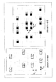
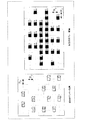
- 31 and 32 show an example of antenna arrangement in the combination of the modified example 3 and the modified example 2.
- An example of arranging the transmitting antenna 106 and the receiving antenna 202 of the above, and an example of arranging the virtual receiving array are shown.
- D TxGroupV 5D V in equation (11).
- the second transmitting antenna group is used for each transmitting antenna (for example, Tx # 4, Tx # 8, Tx # 12, Tx # 16) included in the first transmitting antenna group.
- Each transmitting antenna (for example, Tx3, Tx # 7, Tx # 11, Tx # 15) included in is arranged with a D H shift to the left.
- each transmitting antenna included in the second transmitting antenna group for each transmitting antenna included in the second transmitting antenna group, each transmitting antenna included in the third transmitting antenna group (for example, Tx2, Tx # 6, Tx # 10, Tx # 14). ) Are placed with a D H shift to the left.
- each transmitting antenna included in the fourth transmitting antenna group for example, Tx1, Tx # 5, Tx # 9, Tx # 13). ) Are placed with a D H shift to the left.
- each receiving antenna included in the second receiving antenna group is used for each receiving antenna (for example, Rx # 4, Rx # 8) included in the first receiving antenna group. (For example, Rx # 3 and Rx # 7) are arranged with a D H shift to the left. Further, in FIG. 31, for each receiving antenna included in the second receiving antenna group, each receiving antenna (for example, Rx # 2, Rx # 6) included in the third receiving antenna group is moved to the left. Arranged with a D H shift. Further, in FIG. 31, for each receiving antenna included in the third receiving antenna group, each receiving antenna (for example, Rx # 1, Rx # 5) included in the fourth receiving antenna group is moved to the left. Arranged with a D H shift.
- D RxGroupH 5D H in equation (12).
- each transmitting antenna included in the first transmitting antenna group for example, Tx # 2, Tx # 4, Tx # 6, Tx # 8
- each transmitting included in the second transmitting antenna group for example, Tx # 1, Tx # 3, Tx # 5, Tx # 7)
- Antennas for example, Tx # 1, Tx # 3, Tx # 5, Tx # 7
- the second receiving is performed for each receiving antenna (for example, Rx # 2, Rx # 4, Rx # 6, Rx # 8) included in the first receiving antenna group.
- Each receiving antenna (for example, Rx # 1, Rx # 3, Rx # 5, Rx # 7) included in the antenna group is arranged with a D H shift to the left.
- each MIMO array arrangement shown in FIGS. 31 and 32 by a 0.5 ⁇ about the D H and D V, can be horizontal and vertical element size of the transmitting antenna 106 and receiving antenna 202 than 1 ⁇ ..
- the aperture length of the virtual reception array can be expanded and the angular resolution can be improved.
- the virtual array elements located near the center of the virtual reception array shown in FIGS. 31 and 32 can be densely arranged at D H and DV intervals.
- D H the number of virtual array elements that are densely arranged in D V interval, for example, N TxGroup, N TxGroup_ANT, increases depending on the N RxGroup and N RxGroup_ANT.
- the virtual array elements (N RxGroup ⁇ N TxGroup) -2 are arranged in D V intervals.
- the effect of reducing the grating lobe and side lobe can be improved.
- N TxGroup_ANT and N RxGroup_ANT are larger, the number of virtual array elements arranged in the horizontal direction increases, so that the aperture length of the virtual reception array in the horizontal direction can be expanded and the angular resolution in the horizontal direction can be improved.
- the number of virtual array elements arranged in the vertical direction increases, so that the aperture length of the virtual reception array in the vertical direction can be expanded and the angular resolution in the vertical direction can be improved.
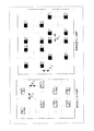
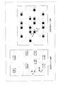
- modification 3 of the basic arrangement 1 is, for example, the arrangement in which the arrangement methods A and B in the modification 2 of the basic arrangement 1 shown in FIG. 20 are combined, and further, in the transmission array antenna and the reception array antenna, respectively.
- the horizontal position of the antenna may be shifted by D H between the transmitting antenna group and the receiving antenna group.
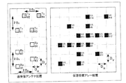
- An example of arranging the transmitting antenna 106 and the receiving antenna 202 of the above, and an example of arranging the virtual receiving array are shown.
- D TxGroupV 5D V in equation (11)
- D RxGroupH 5D H in equation (12).
- the second transmitting antenna group is used for each transmitting antenna (for example, Tx # 4, Tx # 8, Tx # 12, Tx # 16) included in the first transmitting antenna group.
- Each transmitting antenna (for example, Tx3, Tx # 7, Tx # 11, Tx # 15) included in is arranged with a D H shift to the left.
- each transmitting antenna included in the second transmitting antenna group for each transmitting antenna included in the second transmitting antenna group, each transmitting antenna included in the third transmitting antenna group (for example, Tx2, Tx # 6, Tx # 10, Tx # 14). ) Are placed at the same position in the horizontal direction.
- each transmitting antenna included in the fourth transmitting antenna group for each transmitting antenna included in the third transmitting antenna group, each transmitting antenna included in the fourth transmitting antenna group (for example, Tx1, Tx # 5, Tx # 9, Tx # 13). ) Are placed with a D H shift to the left.
- the second receiving is performed for each receiving antenna (for example, Rx # 4, Rx # 8, Rx # 12, Rx # 16) included in the first receiving antenna group.
- Each receiving antenna (for example, Rx # 3, Rx # 7, Rx # 11, Rx # 15) included in the antenna group is arranged with a D H shift to the left.
- each receiving antenna included in the second receiving antenna group each receiving antenna included in the third receiving antenna group (for example, Rx # 2, Rx # 6, Rx # 10, Rx) # 14) are arranged with a D H shift to the right.
- each receiving antenna included in the fourth receiving antenna group for each receiving antenna included in the third receiving antenna group, each receiving antenna included in the fourth receiving antenna group (for example, Rx # 1, Rx # 5, Rx # 9, Rx) # 13) are arranged with a D H shift to the left.
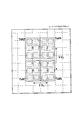
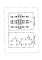
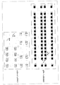
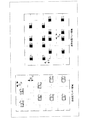
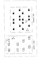
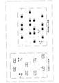
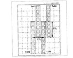
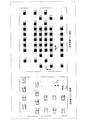
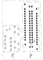
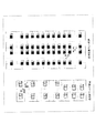
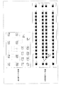
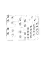
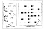
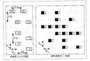
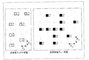
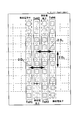
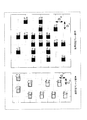
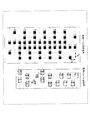
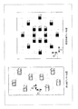
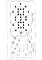
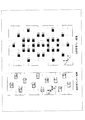
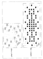
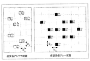
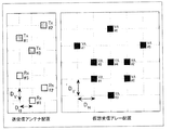
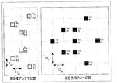
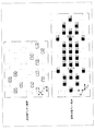
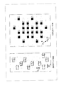
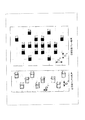
- FIG. 34 shows an arrangement example of the transmitting antenna 106 and the receiving antenna 202 according to the basic arrangement 2 and an arrangement example of the virtual reception array.
- the number of Na 4 (Rx # 1, Rx # 2, Rx # 3 and Rx # 4).
- the transmitting array antennas shown in FIG. 34 are the "first transmitting antenna group" (Tx # 2, Tx # 4 in FIG. 34) and the “second transmitting antenna group” (Tx # 1, Tx in FIG. 34). It consists of # 3).
- Each transmitting antenna group includes two transmitting antenna elements that are in the same position in the vertical direction and have an antenna spacing of 3D H in the horizontal direction (horizontal direction in FIG. 34). Further, the distance between the "first transmitting antenna group” and the "second transmitting antenna group” in the vertical direction (vertical direction in FIG. 34) is, for example, 3D V.
- the receiving array antennas shown in FIG. 34 are the "first receiving antenna group” (Rx # 2, Rx # 4 in FIG. 34) and the “second receiving antenna group” (Rx # 1 in FIG. 34). , Rx # 3).
- Each receiving antenna group includes two receiving antenna elements that are identical in position in the vertical direction and have an antenna spacing of 2D H in the horizontal direction. Further, the vertical distance between the "first receiving antenna group” and the “second receiving antenna group” is, for example, 2D V.
- the transmission array antenna is composed of a plurality of transmission antenna groups, and each of the plurality of transmission antenna groups is, for example, an interval of an integral multiple of D H in the horizontal direction (here). Now, it includes multiple transmitting antennas arranged in 3D H ). In addition, a plurality of transmitting antenna groups are arranged at intervals of 3D V in the vertical direction. In other words, the vertical antenna spacing between the transmitting antenna groups (3D V in FIG. 34) and the horizontal antenna spacing within each transmitting antenna group (3D H in FIG. 34) are the same.
- the reception array antenna is composed of a plurality of reception antenna groups, and each of the plurality of reception antenna groups is, for example, an interval of an integral multiple of D H in the horizontal direction (here, in this case) Includes multiple receiving antennas arranged at 2D H ) intervals.
- a plurality of receiving antenna groups are arranged at intervals of 2D V in the vertical direction. In other words, the horizontal antenna spacing within each receiving antenna group (2D H in FIG. 34) and the vertical antenna spacing between the receiving antenna groups (2D H in FIG. 34) are the same.
- the antenna spacing in the transmitting antenna 106 (3D H in FIG. 34) and the antenna spacing in the receiving antenna 202 (2D H in FIG. 34) are different, for example, the difference is D H.
- the distance a plurality of reception antenna group and spacing a plurality of transmit antenna groups are disposed 3D V (integral multiple of the spacing D V) is arranged 2D V (integral multiple of the spacing D V) the difference is a D V.
- the horizontal direction (horizontal direction) shown in FIG. 34 corresponds to the X axis and the vertical direction (vertical direction) shown in FIG. 34 corresponds to the Y axis direction.
- the position coordinates of the transmission antenna 106 constituting the transmission array antenna are based on the position coordinates (X T_ # 1 , Y T_ # 1 ) of the transmission antenna Tx # 1.
- Positional coordinates of 2 (X T_ # 2 , Y T_ # 2 ) (X T_ # 1 , Y T_ # 1 + 3D V )
- Positional coordinates of transmitting antenna Tx # 3 (X T_ # 3 , Y T_ # 3 ) (X T_ # 1 + 3D H , Y T_ # 1 )
- the position coordinates of the receiving antenna 202 constituting the receiving array antenna are the position coordinates (X) of the receiving antenna Rx # 2 with reference to the position coordinates of the receiving antenna Rx # 1 (X R_ # 1 , Y R_ # 1 ).
- the position coordinates of the virtual reception arrays VA # 1 to VA # 16 (X V_ # 1 , Y V_ # 1 ) to (X V_ # 16 , Y V_ # 16 ) are as follows.
- VA # 1 is represented as the position reference (0,0) of the virtual reception array.
- the virtual reception array elements are arranged at different positions without overlapping. Therefore, since the aperture length of the virtual reception array can be expanded, the main lobe is narrowed and the angular resolution can be improved.
- the virtual array elements VA # 4, VA # 7, VA # 10 and VA # 13 located near the center of the virtual receiving array, D V in the horizontal direction D H interval, vertically They are closely arranged at intervals.
- D H 0.5 [lambda horizontally spacing
- D V 0.5 [lambda intervals in the vertical direction.
- the grating lobe can be reduced as in the basic arrangement 1 (see, for example, FIG. 8).
- the distance D H and the distance D V when set to about 0.5 [lambda, horizontal and vertical element size than the size 1 ⁇ transmit antenna 106 and receive antenna 202 can be designed.
- an antenna using four elements in which two plane patch antennas are arranged vertically and horizontally in a sub-array (however, antenna width W ANT ⁇ 2D H , antenna height H ANT ⁇ 2D V ) Can be applied to at least one antenna element of the transmitting array antenna and the receiving array antenna shown in FIG. 34.
- the horizontal antenna spacing is 3D H and the vertical antenna spacing is 3D V. That is, the antenna spacing (3D H and 3D V ) of the transmitting array antenna shown in FIG. 34 is wider than the antenna spacing (2D H and 2D V ) of the receiving array antenna. Further, the horizontal antenna spacing (3D H ) of the transmitting array antenna shown in FIG. 34 is wider than the horizontal antenna spacing (for example, 2D H in FIG. 8) of the transmitting array antenna in the basic arrangement 1.
- the planar patch antenna having a wider vertical and horizontal spacing than the four-element sub-array shown in FIG. 9A, as shown in FIG. 35, has three vertical elements and three horizontal elements.
- An antenna using 9 elements arranged one by one for the sub-array can be applied.
- the direction estimation unit 214 performs horizontal and vertical direction estimation processing using the received signal of the virtual reception array obtained from the above-mentioned transmission / reception antenna arrangement (see, for example, FIG. 34). For example, since the virtual reception array of the basic arrangement 2 shown in FIG. 34 has the same configuration as the virtual reception array of the basic arrangement 1 (see, for example, FIG. 8), the same performance can be obtained.
- the antenna spacing can be arranged so as to include the element spacing of about 0.5 ⁇ , and the grating lobe can be reduced.
- the aperture length of the virtual reception array can be expanded and the angular resolution can be improved.
- an antenna having a sub-array configuration having an element size of at least 1 ⁇ in the vertical and horizontal directions can be used as the antenna element used for the transmitting antenna 106 and the receiving antenna 202. Therefore, the directivity gain of the antenna can be improved, and the detection performance (for example, the detection distance) of the radar device 10 can be improved.
- the antenna interval can be set wider in either one of the transmitting array antenna and the receiving array antenna (transmission array antenna in FIG. 34) than the other.
- a larger size sub-array can be applied to one array antenna, and the directivity gain of the antenna can be improved.
- the number of transmitting antennas Nt and the number of receiving antennas Na are not limited to these numbers.
- the transmitting array antennas are, for example, the first transmitting antenna group and the second transmitting antenna group having a vertical interval of 3D V , as in the basic arrangement 2 (for example, FIG. 34). It is composed of and. Further, each transmitting antenna group includes two transmitting antenna elements having the same position in the vertical direction and an antenna spacing of 3D H in the horizontal direction, as in the basic arrangement 2.
- the receiving array antenna is the same as the basic arrangement 2, for example, N RxGroup receiving antenna groups having a vertical interval of 2D V (for example, first to NRxGroup ). It is composed of a receiving antenna group).
- each receiving antenna group includes N RxGroup_ANT receiving antenna elements having the same position in the vertical direction and an antenna spacing of 2D H in the horizontal direction.
- Figure 36 in each MIMO array arrangement shown in FIGS. 37 and 38, for example, by a 0.5 ⁇ about the D H and D V, 1 [lambda horizontal and vertical element size of the transmitting antenna 106 and receiving antenna 202 It can be designed to a size larger than the degree.
- the aperture length of the virtual reception array can be expanded and the angular resolution can be improved. it can.
- the virtual array elements located near the center of each virtual reception array shown in FIGS. 36, 37 and 38 can be densely arranged at D H and DV intervals. Further, D H, the number of virtual array elements that are densely arranged in D V interval is increased depending on N RxGroup and N RxGroup_ANT.
- the virtual reception array in the horizontal direction (N RxGroup_ANT ⁇ N TxGroup_ANT) -2 virtual array elements is aligned at D H intervals, in the vertical direction (N RxGroup ⁇ N TxGroup_ANT) -2 virtual array elements D V interval Line up at.
- N RxGroup_ANT the number of virtual array elements arranged in the horizontal direction increases, so that the aperture length of the virtual reception array in the horizontal direction can be expanded and the angular resolution in the horizontal direction can be improved.
- N RxGroup the number of virtual array elements arranged in the vertical direction increases, so that the aperture length of the virtual receive array in the vertical direction can be expanded and the angular resolution in the vertical direction can be improved.
- the vertical antenna spacing of the transmitting antenna group may be set to a constant value (for example, 3D V ), but depending on the number of receiving antenna groups N RxGroup , the virtual receiving array arrangement is performed by the virtual array element. It can be an overlapping arrangement.
- the even-numbered antenna intervals of the transmitting antenna group in the vertical direction are set to the following intervals D TxGroup V2. May be used.
- the distance between the three transmitting antenna groups is ⁇ 3D V , D TxGroup V2 ⁇ .
- the intervals between the four transmitting antenna groups are ⁇ 3D V , D TxGroupV2 , 3D V ⁇ .
- the intervals between the five transmitting antenna groups are ⁇ 3D V , D TxGroupV2 , 3D V , D TxGroup V2 ⁇ .
- D TxGroupV2 3D V in equation (13).
- D TxGroupV2 5D V in equation (13).
- irregular intervals around the center of the virtual reception array e.g., a distance larger than D H and D V
- D TxGroupV2 even greater than the value of formula (13) Good.
- the horizontal antenna spacing of the receiving antenna group may be set to a constant value (for example, 3D H ), but the virtual array arrangement depends on the number of receiving antennas included in the receiving antenna group N RxGroup_ANT. Virtual array elements can be arranged in an overlapping manner.
- the following antenna intervals may be set in the even-numbered antenna intervals of the transmitting antennas included in the transmitting antenna group in the horizontal direction. Such intervals may be used.
- the antenna spacing of the three transmitting antennas is ⁇ 3D H , D TxAnt H ⁇ .
- the antenna spacing of the four transmitting antennas is ⁇ 3D H , D TxAntH , 3D H ⁇ .
- the antenna spacing of the five transmitting antennas is ⁇ 3D H , D TxAntH , 3D H , D TxAnt H ⁇ .
- D TxAntH 3D H in equation (14).
- D TxAntH 5D H in equation (14).
- receive antenna arrangement shown in FIGS. 39 to 42 (e.g., MIMO array arrangement) in, by and 0.5 ⁇ about the D H and D V, the horizontal and vertical elements of the transmit antenna 106 and receive antenna 202
- the size can be designed to be about 1 ⁇ or more.
- the aperture length of the virtual reception array can be expanded and the angular resolution can be improved.
- the virtual array elements located near the center of the virtual reception array shown in FIGS. 39 to 42 can be densely arranged at D H and DV intervals.
- D H the number of virtual array elements that are densely arranged in D V interval, N TxGroup, N TxGroup_ANT, increases depending on the N RxGroup and N RxGroup_ANT.
- the virtual reception array in the horizontal direction (N RxGroup_ANT ⁇ N TxGroup_ANT) -2 virtual array elements is aligned at D H intervals, in the vertical direction (N RxGroup ⁇ N TxGroup) -2 virtual array elements D V interval Line up at.
- the effect of reducing the grating lobe and side lobe can be improved.
- N TxGroup_ANT and N RxGroup_ANT are larger, the number of virtual array elements arranged in the horizontal direction increases, so that the aperture length of the virtual reception array in the horizontal direction can be expanded and the angular resolution in the horizontal direction can be improved.
- the number of virtual array elements arranged in the vertical direction increases, so that the aperture length of the virtual reception array in the vertical direction can be expanded and the angular resolution in the vertical direction can be improved.
- D TxGroupV2 5D H next to Formula (13)
- the D TxAntH 5D H of formula (14).
- each transmitting antenna included in the first transmitting antenna group and the second transmitting antenna group may be arranged by shifting the horizontal position by D H (in other words, shifting). ..
- the direction of D H shift in the horizontal direction may be either the right direction or the left direction for each transmitting antenna included in the second transmitting antenna group with respect to each transmitting antenna included in the first transmitting antenna group.
- FIG. 44 shows, in the transmitting array antenna, for each transmitting antenna (for example, Tx # 2, Tx # 4) included in the first transmitting antenna group, each transmitting antenna (for example, Tx # 2, Tx # 4) included in the second transmitting antenna group. , Tx # 1 and Tx # 3) are shifted to the right by D H , and an example of arranging the transmitting antenna 106 and the receiving antenna 202 and an example of arranging the virtual receiving array are shown.
- each receiving antenna included in the first receiving antenna group and the second receiving antenna group may be arranged with the horizontal position shifted by D H.
- the direction of D H shift in the horizontal direction may be either the right direction or the left direction of each receiving antenna included in the second receiving antenna group with respect to each receiving antenna included in the first receiving antenna group.
- FIG. 45 shows each receiving antenna (for example, Rx # 2, Rx # 4) included in the first receiving antenna group and each receiving antenna (for example, Rx # 2, Rx # 4) included in the second receiving antenna group in the receiving array antenna. , Rx # 1 and Rx # 3) are shifted to the left by D H , and an example of arranging the transmitting antenna 106 and the receiving antenna 202 and an example of arranging the virtual receiving array are shown.
- the arrangement method 2-3C is a method in which the arrangement method 2-3A and the arrangement method 2-3B are combined.
- the transmitting antennas are arranged with a horizontal position shifted by D H between the first transmitting antenna group and the second transmitting antenna group.
- the receiving antennas are arranged with the horizontal position shifted by D H between the first receiving antenna group and the second receiving antenna group.
- the direction of shifting in a horizontal direction D H is, for example, for each transmit antenna included in the first transmission antenna group, each transmit antenna rightward or leftward any included in the second transmission antenna group It may be in the direction. Further, in the horizontal D H shift direction, for example, for each receiving antenna included in the first receiving antenna group, each receiving antenna included in the second receiving antenna group is either rightward or leftward. It may be in the direction.
- FIG. 46 shows an arrangement example of the transmitting antenna 106 and the receiving antenna 202 according to the arrangement method 2-3C, and an arrangement example of the virtual reception array.
- each transmitting antenna for example, Tx # 2, Tx # 4 included in the first transmitting antenna group is compared with each transmitting antenna (for example, Tx # 2, Tx # 4) included in the second transmitting antenna group.
- Tx # 1, Tx # 3) are arranged with a D H shift to the right.
- each receiving antenna included in the second receiving antenna group is used for each receiving antenna (for example, Rx # 2, Rx # 4) included in the first receiving antenna group. (For example, Rx # 1 and Rx # 3) are arranged with a D H shift to the right.
- FIG. 47 shows an arrangement example of the transmitting antenna 106 and the receiving antenna 202 according to the arrangement method 2-3C, and an arrangement example of the virtual reception array.
- each transmitting antenna for example, Tx # 2, Tx # 4 included in the first transmitting antenna group is compared with each transmitting antenna (for example, Tx # 2, Tx # 4) included in the second transmitting antenna group.
- Tx # 1, Tx # 3) are arranged with a D H shift to the right.
- each receiving antenna included in the second receiving antenna group is used for each receiving antenna (for example, Rx # 2, Rx # 4) included in the first receiving antenna group. (For example, Rx # 1 and Rx # 3) are arranged with a D H shift to the left.
- arrangement and different direction and a direction shifting D H in the horizontal direction by the reception antenna group and the transmit antenna group (e.g., FIG. 47) as compared to, shifted D H in the horizontal direction by the reception antenna group and the transmit antenna group
- An arrangement in which the directions are the same is more preferable because the virtual reception array elements are arranged more densely near the center of the virtual reception array arrangement.
- receive antenna arrangement shown in FIGS. 45 to 47 (e.g., MIMO array arrangement) in, by and 0.5 ⁇ about the D H and D V, the horizontal and vertical elements of the transmit antenna 106 and receive antenna 202
- the size can be designed to a size of about 1 ⁇ .
- an antenna using four elements in which two plane patch antennas are arranged vertically and horizontally as shown in FIG. 9A is used for the sub-array (however, the antenna width W ANT ⁇ 2D H , the antenna height). H ANT ⁇ 2D V ) can be applied (not shown).
- flat patch antennas having a wider vertical and horizontal spacing than the four-element sub-array shown in FIG. 9A are arranged in three vertical elements and three horizontal elements.
- An antenna using 9 elements for the sub-array can be applied.
- the horizontal positions of the transmitting antenna included in each transmitting antenna group or the receiving antenna included in each receiving antenna group are aligned with each other in the horizontal direction. different. Therefore, in the third modification of the basic arrangement 2, if the element size in the lateral direction W ANT subarray is smaller than D H, the vertical direction of the element size of the subarray may be arbitrary size. For example, in each of the transmission array antennas of FIGS. 45 to 47, a sub-array in which the plane patch antennas shown in FIG. 25A are arranged vertically by 8 elements and horizontally by 1 element may be used.
- the modified example 3 of the basic arrangement 2 may be combined with the modified example 1 or the modified example 2 of the basic arrangement 2.
- the horizontal position of each transmitting antenna included in the transmitting antenna group is shifted by D H between the transmitting antenna groups. It may be arranged separately.
- the horizontal position of each receiving antenna included in the receiving antenna group is further set between the receiving antenna groups.
- the arrangement may be shifted by D H.
- 48, 49, 50A, 50B, 51A and 51B show an example of antenna arrangement in the combination of the modified example 3 and the modified example 2.
- An example of arranging the receiving antenna 202 and an example of arranging the virtual receiving array are shown.
- D TxGroupV2 5D H next to Formula (13)
- the D TxAntH 5D H of formula (14).
- D TxGroupV2 5D H next to Formula (13)
- D TxAntH 5D H of formula (14).
- the second receiving antenna group is used for each receiving antenna (for example, Rx # 4, Rx # 8, Rx # 12, Rx # 16) included in the first receiving antenna group.
- Each receiving antenna (for example, Rx3, Rx # 7, Rx # 11, Rx # 15) included in the above is arranged with a D H shift to the left.
- each receiving antenna included in the second receiving antenna group each receiving antenna included in the third receiving antenna group (for example, Rx2, Rx # 6, Rx # 10, Rx # 14) )
- Rx1, Rx # 5, Rx # 9, Rx # 13). Are placed with a D H shift to the left.
- An arrangement example of the transmitting antenna 106 and the receiving antenna 202 of the above is shown
- FIG. 50B shows an arrangement example of the virtual reception array.
- D TxGroupV2 5D H next to Formula (13)
- the D TxAntH 5D H of formula (14).
- the second transmitting antenna group is used for each transmitting antenna (for example, Tx # 4, Tx # 8, Tx # 12, Tx # 16) included in the first transmitting antenna group.
- Each transmitting antenna (for example, Tx3, Tx # 7, Tx # 11, Tx # 15) included in is arranged with a D H shift to the left.
- each transmitting antenna included in the second transmitting antenna group for each transmitting antenna included in the second transmitting antenna group, each transmitting antenna included in the third transmitting antenna group (for example, Tx2, Tx # 6, Tx # 10, Tx # 14). ) Are placed with a D H shift to the left.
- each transmitting antenna included in the fourth transmitting antenna group for each transmitting antenna included in the third transmitting antenna group, each transmitting antenna included in the fourth transmitting antenna group (for example, Tx1, Tx # 5, Tx # 9, Tx # 13). ) Are placed with a D H shift to the left.
- the second receiving is performed for each receiving antenna (for example, Rx # 4, Rx # 8, Rx # 12, Rx # 16) included in the first receiving antenna group.
- Each receiving antenna (for example, Rx # 3, Rx # 7, Rx # 11, Rx # 15) included in the antenna group is arranged with a D H shift to the right.
- each receiving antenna included in the second receiving antenna group each receiving antenna included in the third receiving antenna group (for example, Rx # 2, Rx # 6, Rx # 10, Rx) # 14) are arranged with a D H shift to the right.
- each receiving antenna included in the fourth receiving antenna group for each receiving antenna included in the third receiving antenna group, each receiving antenna included in the fourth receiving antenna group (for example, Rx # 1, Rx # 5, Rx # 9, Rx) # 13) are arranged with a D H shift to the right.
- An arrangement example of the transmitting antenna 106 and the receiving antenna 202 is shown
- FIG. 51B shows an arrangement example of the virtual receiving array.
- D TxGroupV2 5D H next to Formula (13)
- the D TxAntH 5D H of formula (14).
- the second transmitting antenna group is used for each transmitting antenna (for example, Tx # 4, Tx # 8, Tx # 12, Tx # 16) included in the first transmitting antenna group.
- Each transmitting antenna (for example, Tx3, Tx # 7, Tx # 11, Tx # 15) included in is arranged with a D H shift to the left.
- each transmitting antenna included in the third transmitting antenna group for each transmitting antenna included in the first transmitting antenna group, each transmitting antenna included in the third transmitting antenna group (for example, Tx2, Tx # 6, Tx # 10, Tx # 14). ) Are placed with a D H shift to the right.
- each transmitting antenna included in the fourth transmitting antenna group for each transmitting antenna included in the third transmitting antenna group, each transmitting antenna included in the fourth transmitting antenna group (for example, Tx1, Tx # 5, Tx # 9, Tx # 13). ) Are placed with a D H shift to the left.
- the second receiving is performed for each receiving antenna (for example, Rx # 4, Rx # 8, Rx # 12, Rx # 16) included in the first receiving antenna group.
- Each receiving antenna (for example, Rx # 3, Rx # 7, Rx # 11, Rx # 15) included in the antenna group is arranged with a D H shift to the left.
- each receiving antenna included in the second receiving antenna group each receiving antenna included in the third receiving antenna group (for example, Rx # 2, Rx # 6, Rx # 10, Rx) # 14) are arranged with a D H shift to the right.
- each receiving antenna included in the fourth receiving antenna group for each receiving antenna included in the third receiving antenna group, each receiving antenna included in the fourth receiving antenna group (for example, Rx # 1, Rx # 5, Rx # 9, Rx) # 13) are arranged with a D H shift to the left.
- the size can be designed to a size of 1 ⁇ or more.
- the opening length of the virtual reception array can be expanded and the angle can be increased.
- the resolution can be improved.
- each transmitting antenna group N TxGroup When the number of transmitting antenna groups N TxGroup is 3 or more, the horizontal position of each transmitting antenna included in each transmitting antenna group may be shifted in a certain direction (right or left), and each transmitting antenna group may be arranged. The horizontal position of each transmitting antenna included in the above may be changed for each transmitting antenna group without shifting to the right or left.
- the horizontal position of each receiving antenna included in each receiving antenna group may be shifted in a certain direction (right or left), and each receiving antenna may be arranged. The horizontal position of each receiving antenna included in the group may not be shifted to the right or left, and the direction may be changed for each receiving antenna group.
- virtual array elements located near the center of the virtual reception array can be densely arranged at D H and DV intervals.
- D H the number of virtual array elements that are densely arranged in D V interval, for example, N TxGroup, N TxGroup_ANT, increases depending on the N RxGroup and N RxGroup_ANT.
- the virtual array elements (N TxGroup_ANT ⁇ N RxGroup_ANT) -2 is aligned with D H intervals
- N TxGroup_ANT and N RxGroup_ANT are larger, the number of virtual array elements arranged in the horizontal direction increases, so that the aperture length of the virtual reception array in the horizontal direction can be expanded and the angular resolution in the horizontal direction can be improved.
- the number of virtual array elements arranged in the vertical direction increases, so that the aperture length of the virtual reception array in the vertical direction can be expanded and the angular resolution in the vertical direction can be improved.
- ⁇ Basic arrangement 3> 52A to 52D show an arrangement example of the transmitting antenna 106 and the receiving antenna 202 according to the basic arrangement 3 and an arrangement example of the virtual reception array.
- the transmitting array antennas shown in FIGS. 52A to 52D are the "first transmitting antenna group" (Tx # 2, Tx # 4 in FIGS. 52A to D) and the "second transmitting antenna group” (in FIGS. 52A to 52D). , Tx # 1, Tx # 3).
- Each transmitting antenna group includes two transmitting antenna elements having the same position in the vertical direction and an antenna spacing of 2D H in the horizontal direction (horizontal direction in FIGS. 52A to 52D). Further, the vertical distance between the "first transmitting antenna group” and the "second transmitting antenna group” (vertical direction in FIGS. 52A to 52D) is, for example, 2D V.
- the horizontal positions of the transmitting antennas included in the first transmitting antenna group and the second transmitting antenna group are different positions deviated by D H.
- the horizontal position of each transmitting antenna included in the second transmitting antenna group is such that the horizontal position of the transmitting antenna included in the first transmitting antenna group is shifted by + D H or -D H. is there.
- the receiving array antennas shown in FIGS. 52A to 52D are a "first receiving antenna group" (Rx # 1 and Rx # 2 in FIGS. 52A to 52D) and a “second receiving antenna group” (FIGS. 52A to 52A). In D, it is composed of Rx # 3 and Rx # 4).
- Each receiving antenna group includes two receiving antenna elements that are in the same position in the horizontal direction and have an antenna spacing of 2 DV in the vertical direction. Further, the horizontal distance between the "first receiving antenna group" and the "second receiving antenna group” is, for example, 2D H.
- the vertical position of the reception antennas included in the first reception antenna group and the second reception antenna group becomes a position different from each other offset D V.
- the vertical position of the reception antennas included in the second receiving antenna groups, the vertical position of receiving antennas included in the first reception antenna group, in an arrangement shifted arrangement or -D V shifted + D V is there.
- the respective arrangement positions of the transmission antenna included in the transmission array antenna and the respective arrangement positions of the reception antenna included in the reception array antenna are in the horizontal direction and the vertical direction.
- the relationship is rotated by + 90 ° or ⁇ 90 °.
- the respective arrangement positions of the transmission antenna included in the transmission array antenna and the respective arrangement positions of the reception antenna included in the reception array antenna are in the horizontal direction and the vertical direction.
- the relationship is rotated by + 90 ° or ⁇ 90 ° and inverted.
- vertical combination of two kinds of shift amounts [Delta] V Rx group (+ D V, -D V) may be any combination.
- the + D H direction is the right direction
- the -D H direction is the left direction.
- + D V direction in FIG. 52A ⁇ D is the upper direction
- -D V is the downward direction.
- the MIMO array arrangement and the virtual reception array arrangement in the case of V ) are shown respectively.
- the virtual reception array arrangements obtained by the MIMO array arrangements for each antenna group deviation amount shown in FIGS. 52A to 52D have rotationally symmetric arrangements, and the same characteristics of angle measurement performance can be obtained.
- the horizontal direction (horizontal direction) shown in FIG. 52A corresponds to the X axis and the vertical direction (vertical direction) shown in FIG. 52A corresponds to the Y axis direction.
- the position coordinates of the transmit antenna 106 constituting the transmit array antenna are based on the position coordinates of the transmit antenna Tx # 1 (X T_ # 1 , Y T_ # 1 ).
- the position coordinates of the receiving antenna 202 constituting the receiving array antenna are the position coordinates (X) of the receiving antenna Rx # 2 with reference to the position coordinates of the receiving antenna Rx # 1 (X R_ # 1 , Y R_ # 1 ).
- the position coordinates of the virtual receiving arrays VA # 1 to VA # 16 (X V_ # 1 , Y V_ # 1 ) to (X V_ # 16 , Y V_ # 16 ) are as follows.
- VA # 1 is represented as the position reference (0,0) of the virtual reception array.
- the virtual reception array elements are arranged at different positions without overlapping. Therefore, since the aperture length of the virtual reception array can be expanded, the main lobe is narrowed and the angular resolution can be improved.
- the virtual array elements VA # 4, VA # 7, VA # 10 and VA # 13 located near the center of the virtual reception array shown in FIGS. 52A ⁇ D is, D V intervals in the horizontal direction D H interval, vertically Each is densely arranged.
- the grating lobe can be reduced as in the basic arrangement 1 (see, for example, FIG. 8).
- the distance D if the H and the distance D V was about 0.5 [lambda, the element size in the horizontal direction and the vertical direction of more than 1 ⁇ transmit antennas 106 and receiving antenna 202 Can be designed to size.
- an antenna using four elements in which two plane patch antennas are arranged vertically and horizontally in a sub-array (however, antenna width W ANT ⁇ 2D H , antenna height H ANT ⁇ 2D V ) Can be applied to at least one of the transmitting array antenna and the receiving array antenna shown in FIGS. 52A to 52D.
- N TxHGroup1_ANT the number of transmitting antennas included in the first transmitting antenna group
- N TxHGroup2_ANT the number of transmitting antennas included in the second transmitting antenna group
- N RxVGroup1_ANT the number of receiving antennas included in the first receiving antenna group
- N RxVGroup2_ANT the number of receiving antennas included in the second receiving antenna group
- FIGS. 53A to 53D there is a difference of one antenna between the number of transmitting antennas N TxHGroup1_ANT included in the first transmitting antenna group and the number of transmitting antennas N TxHGroup2_ANT included in the second transmitting antenna group, and the first receiving antenna.
- the configuration example in which the number of MIMO array antennas is minimized when the number of receiving antennas included in the group N RxVGroup1_ANT and the number of receiving antennas included in the second receiving antenna group N RxVGroup2_ANT are the same is shown.
- N TxHGroup1_ANT 1 (Tx # 2)
- N TxHGroup2_ANT 2 (Tx # 1, Tx # 3)
- ( ⁇ H Tx , ⁇ V Rx ) (-D H , -D V ).
- N TxHGroup1_ANT 1 (Tx # 2)
- N TxHGroup2_ANT 2 (Tx # 1, Tx # 3)
- ( ⁇ H Tx, ⁇ V Rx) (- D H, + D V) MIMO array arrangement where An example and an example of arranging a virtual reception array are shown.
- N TxHGroup1_ANT 2 (Tx # 2, Tx # 3)
- N TxHGroup2_ANT 1 (Tx # 1)
- ( ⁇ H Tx , ⁇ V Rx ) (+ D H , -D V ).
- Figure 54A ⁇ D includes a first number of transmit antennas N TxHGroup2_ANT the number of transmit antennas N TxHGroup1_ANT included in the transmission antenna group and included in the second transmission antenna group is equal, it is included in the first reception antenna group shows a configuration example in which the number of MIMO array antenna when there is a difference of 1 antenna branching number N RxVGroup1_ANT and the number of reception antennas N RxVGroup2_ANT included in the second reception antenna group receiving antenna is minimized.
- N TxHGroup1_ANT -N TxHGroup2_ANT 0 and
- 1
- the number of receiving antennas is 3.
- N RxHGroup1_ANT 1 (Rx # 1)
- N RxHGroup2_ANT 2 (Rx # 2, Rx # 3)
- MIMO array example of arrangement when the ( ⁇ H Tx, ⁇ V Rx) (+ D H, + D V)
- an example of virtual reception array arrangement is shown.
- N RxHGroup1_ANT 2 (Rx # 1, Rx # 2)
- N RxHGroup2_ANT 1 (Rx # 3)
- ( ⁇ H Tx , ⁇ V Rx ) (-D H , -D V ).
- N RxHGroup1_ANT 2 (Rx # 1, Rx # 2)
- N RxHGroup2_ANT 1 (Rx # 3)
- ( ⁇ H Tx , ⁇ V Rx ) (+ D H , -D V ).
- FIGS. 55A to 55D there is a difference of one antenna between the number of transmitting antennas N TxHGroup1_ANT included in the first transmitting antenna group and the number of transmitting antennas N TxHGroup2_ANT included in the second transmitting antenna group, and the first receiving antenna.
- the configuration example in which the number of MIMO array antennas is minimized when there is a difference of one antenna between the number of receiving antennas included in the group N RxVGroup1_ANT and the number of receiving antennas included in the second receiving antenna group N RxVGroup2_ANT is shown.
- N TxVGroup1_ANT 1 (Tx # 2)
- N TxVGroup2_ANT 2 (Tx # 1, Tx # 3)
- N RxHGroup1_ANT 2 (Rx # 1, Rx # 2)
- N RxHGroup2_ANT 1 (Rx # 3).
- ( ⁇ H Tx , ⁇ V Rx ) (-D H , -D V )
- an example of MIMO array arrangement and an example of virtual reception array arrangement are shown.
- N TxVGroup1_ANT 1 (Tx # 2)
- N TxVGroup2_ANT 2 (Tx # 1, Tx # 3)
- N RxHGroup1_ANT 1 (Rx # 1)
- N RxHGroup2_ANT 2 (Rx # 2, Rx # 3).
- ( ⁇ H Tx, ⁇ V Rx ) (- D H, + MIMO array example of arrangement when the D V), and shows a virtual reception array arrangement example.
- the transmitting array antenna includes three transmitting antennas
- the receiving array antenna includes three receiving antennas.
- two of the three transmitting antennas are arranged at a distance of 2D H (in other words, twice the interval of D H ) in the horizontal direction, for example. Will be done. Further, the remaining one transmitting antenna among the three transmitting antennas is arranged, for example, in the horizontal direction at a distance of D H from the two transmitting antennas (in other words, in the intermediate position), and in the vertical direction, the above 2 One of the 2D V interval from the transmitting antenna (in other words, twice the distance D V) are spaced apart.
- two receiving antennas of the three receive antennas is, for example, 2D V in the vertical direction (in other words, twice the distance D V) away Be placed.
- the remaining one of the three receiving antennas is arranged, for example, vertically separated from the two receiving antennas by a DV interval (in other words, at an intermediate position), and horizontally, as described above. They are placed 2D H apart (in other words, twice the D H ) from the two receiving antennas.
- the respective arrangement positions of the three transmitting antennas and the respective arrangement positions of the three receiving antennas are in the horizontal direction (for example, the X axis) and the vertical direction (for example, the Y axis).
- the transmitting array antenna and the receiving array antenna are rotated by ⁇ 90 degrees.
- the transmit / receive antenna arrangement according to the basic arrangement 3 and each modification of the basic arrangement 3 includes at least an antenna arrangement having an arrangement relationship of the three transmitting antennas or the three receiving antennas described above.
- the opening length of the virtual reception array can be expanded. , Angle resolution can be improved.
- the virtual array elements located near the center of the virtual reception array are densely arranged at D H and DV intervals.
- the grating lobe can be reduced.
- the distance D if the H and the distance D V was about 0.5 [lambda, horizontal and vertical size of more than about 1 ⁇ the element size of the transmit antenna 106 and receive antenna 202 Can be designed to.
- an antenna using four elements in which two flat patch antennas are arranged vertically and horizontally in a sub-array (however, antenna width W ANT ⁇ 2D H , antenna height H ANT ⁇ 2D V ) can be obtained.
- 52A to D, 53A to D, 54A to 54D, and 55A to 55D which can be applied to at least one antenna element of the transmitting array antenna and the receiving array antenna.
- the transmitting antenna 106 if the element size of W ANT in the horizontal direction is smaller than D H , an antenna of any size can be used in the vertical direction.
- FIG. 56A shows an example in which a sub-array in which the plane patch antennas shown in FIG. 25A are arranged vertically by 8 elements and horizontally by 1 element is applied to the antenna arrangement shown in FIG. 52A.
- a non-feeding element (dummy element) may be arranged in addition to the transmission array antenna shown in FIG. 56A. With the non-feeding element, the influence of the coupling between the antennas by the adjacent antennas can be made uniform for each antenna, and the directional characteristics of each transmitting antenna (Tx # 1 to # 4) can be made uniform.
- the directivity gain of the antenna can be improved and the detection performance (for example, the detection distance) in the radar device 10 can be improved.
- the direction estimation unit 214 performs horizontal and vertical direction estimation processing using the received signal of the virtual reception array obtained from the above-mentioned transmission / reception antenna arrangement. Since the processing for the virtual reception array of the basic arrangement 3 in the direction estimation unit 214 is the same as that of the basic arrangement 1, the description thereof will be omitted here.
- the horizontal and vertical antenna spacing of the transmitting antenna 106 is 1 ⁇ or more
- the horizontal and vertical antenna spacing of the receiving antenna 202 is also 1 ⁇ or more.
- the directivity of each antenna is calculated as omnidirectional.
- FIG. 57 plots the output of the arrival direction estimation evaluation function value in the horizontal ⁇ 90 degree range and the vertical ⁇ 90 degree range when the target true value is 0 degrees horizontally and 0 degrees vertically.
- the grating lobe is reduced in directions other than the horizontal 0 degree and the vertical 0 degree of the target true value, as compared with, for example, FIG. 1A.
- the ratio of the peak power value of the main lobe in the horizontal 0 degree and vertical 0 degree directions to the peak power value of the highest side lobe excluding the main lobe in directions other than horizontal 0 degree and vertical 0 degree ( PSLR) is about 0.3.
- the MIMO array arrangement according to the basic arrangement 3 even if the element size in the vertical direction or the horizontal direction of the antennas used for the transmission array antenna and the reception array antenna is about 1 ⁇ , the horizontal direction and the vertical direction in the virtual reception array
- the antenna spacing in the direction can be arranged so as to include the element spacing of about 0.5 ⁇ , and the grating lobe can be reduced.
- the aperture length of the virtual reception array can be expanded and the angular resolution can be improved.
- the transmission array antenna first transmission antenna number N TxHGroup1_ANT included in the transmission antenna groups, and may increase the number of antennas N TxHGroup2_ANT included in the second transmission antenna group. Further, in the receiving array antenna, the number of antennas included in the first receiving antenna group N RxVGroup1_ANT and the number of antennas included in the second receiving vertical antenna group N RxVGroup2_ANT may be increased.
- N TxHGroup1_ANT 4 (Tx # 2, Tx # 4, Tx # 6, Tx # 8)
- each MIMO array arrangement shown in FIGS. 58 to 61 for example, D by H and D V to about 0.5 [lambda, the element size in the horizontal direction and the vertical direction of more than about 1 ⁇ transmit antennas 106 and receiving antenna 202 Can be designed to size.
- the aperture length of the virtual reception array can be expanded and the angular resolution can be improved.
- the virtual array elements located near the center of each virtual reception array shown in FIGS. 58 to 61 can be densely arranged at D H and DV intervals. Further, D H, the number of virtual array elements that are densely arranged in D V interval, N TxHGroup1_ANT, N TxHGroup2_ANT, increases depending on the N RxVGroup1_ANT and N RxVGroup2_ANT.
- the virtual reception array in the horizontal direction aligned with the virtual array elements D H interval (N TxHGroup1_ANT + N TxHGroup2_ANT), in the vertical direction the virtual array elements (N RxVGroup1_ANT + N RxVGroup2_ANT) arranged at D V intervals.
- a virtual array elements (N TxHGroup1_ANT + N TxHGroup2_ANT) -2 of D H intervals in the horizontal direction, and the virtual array elements (N RxVGroup1_ANT + N RxVGroup2_ANT) -2 of D V intervals in the vertical direction Are lined up in a vertical and horizontal rectangular shape.
- N TxGroup1_ANT and N TxHGroup2_ANT are larger, the number of virtual array elements arranged in the horizontal direction increases, so that the aperture length of the virtual reception array in the horizontal direction can be expanded and the angular resolution in the horizontal direction can be improved.
- N RxVGroup1_ANT and N RxVGroup2_ANT are larger, the number of virtual array elements arranged in the vertical direction increases, so that the aperture length of the virtual reception array in the vertical direction can be expanded and the angular resolution in the vertical direction can be improved.
- the directivity of each antenna is calculated as omnidirectional.
- FIG. 62 plots the output of the arrival direction estimation evaluation function value in the horizontal ⁇ 90 degree range and the vertical ⁇ 90 degree range when the target true value is 0 degrees horizontally and 0 degrees vertically.
- the grating lobe is reduced in directions other than the horizontal 0 degree and the vertical 0 degree of the target true value.
- the ratio (PSLR) of the peak power value of the highest side lobe excluding the main lobe to the peak power value of the main lobe in the horizontal 0 degree and vertical 0 degree directions is about 0.13, for example.
- N TxHGroup1_ANT, N TxHGroup2_ANT and N RxVGroup1_ANT by increasing the N RxVGroup2_ANT, improving the effect of reducing the side lobes it can be confirmed.
- FIG. 62 as compared with FIG.
- the vertical antenna spacing of the transmitting antenna group may be set to a constant value (for example, 2D V ), but virtual reception depends on the number of receiving antennas included in the receiving antenna group N RxVGroup1_ANT and N RxVGroup2_ANT.
- the array arrangement can be an arrangement in which virtual array elements overlap.
- the even-numbered antenna intervals of the transmitting antenna group in the vertical direction are set to the following intervals D TxHGroupV. May be used.
- D TxHGroupV 4D V.
- the distance between the three transmitting antenna groups is ⁇ 2D V , D TxHGroup V ⁇ .
- the intervals between the four transmitting antenna groups are ⁇ 2D V , D TxHGroupV , 2D V ⁇ .
- N RxGroup_ANT 5 the spacing between the five transmitting antenna groups is ⁇ 2D V , D TxHGroupV , 2D V , D TxHGroupV ⁇ .
- N TxHGroup3_ANT represents the number of transmitting antennas included in the third transmitting antenna group
- N TxHGroup4_ANT represents the number of transmitting antennas included in the fourth transmitting antenna group.
- D TxHGroupV 2D V in equation (15).
- the deviation amount ⁇ V Rx (2,1) of the second receiving antenna group (Rx # 3, Rx # 4) with respect to the first receiving antenna group (Rx # 1, Rx # 2 ) is ⁇ V.
- Rx (2,1) -D V
- the deviation amount ⁇ H Tx (2,1) of the second transmitting antenna group (Tx # 3, Tx # 7) with respect to the first transmitting antenna group (Tx # 4, Tx # 8 ) is ⁇ D.
- H be, and let the deviation amount ⁇ H Tx (3,2) of the third transmitting antenna group (Tx # 2, Tx # 6) with respect to the second transmitting antenna group be + D H, and let the fourth transmitting antenna group be the fourth.
- the deviation amount ⁇ H Tx (4,3) of the transmitting antenna group (Tx # 1, Tx # 5) be -D H.
- the shift amount is two (+ D V, -D V) may be any combination of.
- the + DV direction is upward, -D V is downward, + D H direction is right, and -D H is left.
- D TxHGroupV 4D V in equation (15).
- the deviation amount ⁇ H Tx (2,1) of the second transmitting antenna group (Tx # 3, Tx # 7) with respect to the first transmitting antenna group (Tx # 4, Tx # 8 ) is ⁇ .
- D H be, and let the deviation amount ⁇ H Tx (3,2) of the third transmitting antenna group (Tx # 2, Tx # 6) with respect to the second transmitting antenna group be + D H, and let the third transmitting antenna group be the third.
- the deviation amount ⁇ H Tx (4,3) of the transmitting antenna group (Tx # 1, Tx # 5) of 4 is -D H.
- the shift amount is two (+ D V, -D V) may be any combination of.
- the + DV direction is upward, -D V is downward, + D H direction is right, and -D H is left.
- the horizontal antenna spacing of the receiving antenna group may be set to a constant value (for example, 2D H ), but it is virtual depending on the number of transmitting antennas N TxHGroup1_ANT and N TxHGroup2_ANT included in the transmitting antenna group.
- the reception array arrangement may be an arrangement in which virtual array elements overlap.
- the following interval D RxV Group H is used for the even-numbered interval among the horizontal intervals of the receiving antenna group. You can.
- N TxVGroupH 3D H
- the horizontal distance between the three receiving antenna groups is ⁇ 2D H , D RxVGroup H ⁇ .
- the horizontal spacing of the four receiving antenna groups is ⁇ 2D H , D RxVGroupH , 2D H ⁇ .
- the horizontal spacing of the five receiving antenna groups is ⁇ 2D H , D RxVGroupH , 2D H , D RxVGroup H ⁇ .
- N RxVGroup3_ANT represents the number of receiving antennas included in the third receiving antenna group
- N RxVGroup4_ANT represents the number of receiving antennas included in the fourth receiving antenna group.
- D RxVGroupH 2D H in equation (16).
- the deviation amount ⁇ V Rx (2,1) of the second receiving antenna group (Rx # 3, Rx # 4) with respect to the first receiving antenna group (Rx # 1, Rx # 2 ) is ⁇ D. and is V
- the fourth to the third reception antenna group Let the deviation amount ⁇ V Rx (4,3) of the receiving antenna group (Rx # 7, Rx # 8) be -D V.
- the shift amount is two (+ D V, -D V) may be any combination of.
- the + DV direction is the upward direction
- the -D V direction is the downward direction.
- D RxVGroupH 4D H in equation (16).
- the deviation amount ⁇ V Rx (2,1) of the second receiving vertical antenna group (Rx # 3, Rx # 4) with respect to the first receiving antenna group (Rx # 1, Rx # 2 ) is shown.
- -D V the second third reception antenna group for the reception antenna group (Rx # 5, Rx # 6 ) shift amount [Delta] V Rx a (3,2) + D V of the relative third reception antenna group
- the shift amount is two (+ D V, over D V) may be any combination of.
- the + DV direction is upward, -D V is downward, + D H direction is right, and -D H is left.
- irregular intervals around the center of the virtual reception array e.g., a distance larger than D H and D V
- D RxVGroupH even greater than the value of formula (16) Good.
- receive antenna arrangement shown in FIG. 63 through FIG. 66 (e.g., MIMO array arrangement) in, for example, by a 0.5 ⁇ about the D H and D V, horizontal and vertical transmission antenna 106 and receiving antenna 202
- the element size of can be designed to be about 1 ⁇ or more.
- the aperture length of the virtual reception array can be expanded and the angular resolution can be improved.
- the virtual array elements located near the center of the virtual reception array shown in FIGS. 63 to 66 can be densely arranged at D H and DV intervals.
- the virtual reception array arranged in rows at 0.5 ⁇ (N TxHGroup1_ANT + N TxHGroup2_ANT ) ⁇ N virtual array elements D H interval RxVGroup in the horizontal direction, 0.5 ⁇ (N RxVGroup1_ANT + N RxVGroup2_ANT) in the vertical direction ⁇ N TxHGroup virtual array elements are arranged in a row in D V intervals.
- the number of transmitting antennas N TxHGroup (ntvg) _ANT included in each transmitting antenna group and the number of receiving antenna groups N RxVGroup are larger, the number of virtual array elements arranged in the horizontal direction increases, so that virtual reception in the horizontal direction increases.
- the aperture length of the array can be extended and the horizontal angular resolution can be improved.
- the larger the number of receiving antennas N RxVGroup (nrhg) _ANT included in each receiving antenna group and the number of transmitting antenna groups N TxHGroup the larger the number of virtual array elements arranged in the vertical direction.
- the aperture length of the receiving array can be extended and the vertical angular resolution can be improved.
- the deviation amount ⁇ H Tx (2,1) of the second transmitting antenna group (Tx # 3, Tx # 7) with respect to the first transmitting antenna group (Tx # 4, Tx # 8 ) is ⁇ .
- D H be, and let the deviation amount ⁇ H Tx (3,2) of the third transmitting antenna group (Tx # 2, Tx # 6) with respect to the second transmitting antenna group be -D H, and let the third transmitting antenna group be the third.
- the deviation amount ⁇ H Tx (4,3) of the transmitting antenna group (Tx # 1, Tx # 5) of 4 is -D H.
- the shift amount is two (+ D V, -D V) may be any combination of.
- the deviation amount ⁇ V Rx (2,1) of the second receiving antenna group (Rx # 3, Rx # 4) with respect to the first receiving antenna group (Rx # 1, Rx # 2 ) is -D. and is V
- the third reception antenna group for the second reception antenna group (Rx # 5, Rx # 6 ) of the shift amount [Delta] V Rx (3,2) is set to + D V
- the deviation amount ⁇ V Rx (4,3) of the receiving antenna group (Rx # 7, Rx # 8 ) is -D V.
- the shift amount is two (+ D V, -D V) may be any combination of.
- the + DV direction is the upward direction
- the -D V direction is the downward direction
- the + D H direction is the right direction
- the -D H direction is the left direction.
- the deviation amount ⁇ H Tx (2,1) of # 15) is -D H
- the third transmitting antenna group (Tx # 2, Tx # 6, Tx # 10, Tx # 14) with respect to the second transmitting antenna group deviation amount [Delta] H Tx (3,2) are, + D and H
- the deviation amount [Delta] H Tx in the fourth transmission antenna group for the third transmission antenna group (Tx # 1, Tx # 5 , Tx # 9, Tx # 13) (4,3) is -D H.
- the shift amount is two (+ D V, -D V) may be any combination of.
- the second receiving antenna group (Rx # 5, Rx # 6, Rx # 7, Rx) with respect to the first receiving antenna group (Rx # 1, Rx # 2, Rx # 3, Rx # 4)
- the deviation amount ⁇ V Rx (2,1) of # 8) is -D V
- the third receiving antenna group (Rx # 9, Rx # 10, Rx # 11, Rx # 12) with respect to the second receiving antenna group.
- deviation amount [Delta] V Rx (3,2) is set to + D V
- the fourth reception antenna group for the third reception antenna group (Rx # 13, Rx # 14 , Rx # 15, Rx # 16) of the shift amount [Delta] V Rx ( 4,3) is -D V.
- the shift amount is two (+ D V, over D V) may be any combination of.
- + D V direction is the upper direction
- -D V direction is the lower direction
- + D H direction is a right direction
- -D H direction is a left direction.
- FIG. 69 shows an arrangement example of the transmitting antenna 106 and the receiving antenna 202 according to the basic arrangement 4 and an arrangement example of the virtual reception array.
- the number of Na 4 (Rx # 1, Rx # 2, Rx # 3 and Rx # 4).
- the transmitting array antennas shown in FIG. 69 are, for example, a "first transmitting antenna group" (Tx # 2, Tx # 4 in FIG. 69) and a “second transmitting antenna group” (Tx # 1 in FIG. 69). , Tx # 3).
- the transmitting antenna adjacent the interval of the 2D H in the horizontal direction are arranged (in other words, twice the distance D H) apart, spacing away of vertically D V Is placed.
- transmit antennas included in each transmit antenna group, 2D H in the horizontal direction (in other words, the upper left oblique direction) vertical direction toward the lower right in the antenna spacing D V linearly in Be placed.
- the second transmitting antenna group is arranged so as to be shifted D H to the left in the horizontal direction and 2 DV V downward in the vertical direction with respect to the first transmitting antenna group.
- the transmit antenna groups adjacent shown in FIG. 69 the spacing of the horizontal direction D H and, (in other words, twice the distance D V) 2D V in the vertical direction in shifted relation.
- the receiving array antennas shown in FIG. 69 are, for example, a "first receiving antenna group" (Rx # 2, Rx # 4 in FIG. 69) and a “second receiving antenna group” (Rx in FIG. 69). It consists of # 1 and Rx # 3).
- Each receiving antenna groups, respectively, antenna spacing in the horizontal direction is the 2D H
- the vertical direction includes two receive antenna elements antenna spacing is D V.
- the receiving antennas adjacent spacing 2D H in the horizontal direction are arranged (in other words, twice the distance D H) apart, spacing away of vertically D V Is placed.
- the receiving antenna included in each receiving antenna groups, 2D H in the horizontal direction (in other words, the left oblique downward direction) in the vertical direction upper right direction in the antenna spacing D V linearly in Be placed.
- the second receiving antenna group is arranged so as to be shifted D H to the right in the horizontal direction and 2 DV V downward in the vertical direction with respect to the first receiving antenna group.
- reception antenna group adjacent shown in FIG. 69 the spacing of the horizontal direction D H and, (in other words, twice the distance D V) 2D V in the vertical direction in shifted relation.
- each of the transmitting antennas Tx # 1 to Tx # 4 is arranged at different positions in both the horizontal direction and the vertical direction.
- each of the receiving antennas Rx # 1 to Rx # 4 is arranged at different positions in both the horizontal direction and the vertical direction.
- each arrangement position of the transmission antenna and each arrangement position of the reception antenna have a line-symmetrical relationship (in other words, in other words, with respect to a line parallel to the horizontal direction or the vertical direction). It is in an inverted relationship).
- the horizontal direction (horizontal direction) shown in FIG. 69 corresponds to the X axis and the vertical direction (vertical direction) shown in FIG. 69 corresponds to the Y axis direction.
- the position coordinates of the transmit antenna 106 constituting the transmit array antenna are based on the position coordinates (X T_ # 1 , Y T_ # 1 ) of the transmit antenna Tx # 1.
- Positional coordinates of 2 (X T_ # 2 , Y T_ # 2 ) (X T_ # 1 + D H , Y T_ # 1 + 2D V )
- Positional coordinates of transmitting antenna Tx # 3 (X T_ # 3 , Y T_ # 3 ) (X T_ # 1 + 2D H , Y T_ # 1 -D V )
- the position coordinates of the transmitting antenna Tx # 4 (X T_ # 4 , Y T_ # 4 ) (X T_ # 1 + 3D H, denoted as Y T_ # 1 + D V) .
- the position coordinates of the receiving antenna 202 constituting the receiving array antenna are the position coordinates (X) of the receiving antenna Rx # 2 with reference to the position coordinates of the receiving antenna Rx # 1 (X R_ # 1 , Y R_ # 1 ).
- the position coordinates of the virtual receiving arrays VA # 1 to VA # 16 (X V_ # 1 , Y V_ # 1 ) to (X V_ # 16 , Y V_ # 16 ) are as follows.
- VA # 1 is represented as the position reference (0,0) of the virtual reception array.
- the virtual reception array elements are arranged at different positions without overlapping. Therefore, since the aperture length of the virtual reception array can be expanded, the main lobe is narrowed and the angular resolution can be improved.
- the virtual array elements VA # 2, VA # 7, VA # 9, VA # 4, VA # 15, VA # 10, VA # 8 and VA # 13 located near the center of the virtual reception array shown in FIG. 69 are , D H intervals in the horizontal direction, are densely arranged at D V intervals in the vertical direction.
- D H 0.5 [lambda intervals in the horizontal direction
- D H 0.5 [lambda intervals in the vertical direction.
- the virtual array elements which are closely spaced D H and the distance D V e.g., VA # 2, VA # 7 , VA # 9, VA # 4, VA
- the element at the position corresponding to the coordinates surrounded by # 15, VA # 10, VA # 8 and VA # 13) is missing.
- portions radar device 10 is, for example, surrounding the missing portion, by performing interpolation processing using the reception signal of the virtual array elements which are closely spaced D H and spacing D V, which are the missing
- the received signal of the element can be received approximately.
- the distance D if the H and the distance D V was about 0.5 [lambda, horizontal and vertical size of more than about 1 ⁇ the element size of the transmit antenna 106 and receive antenna 202 Can be designed to.
- FIG. 9A an antenna using four elements in which two flat patch antennas are arranged vertically and horizontally in a sub-array (however, antenna width W ANT ⁇ 2D H , antenna height H ANT ⁇ 2D V ) can be obtained.
- FIG. 70A shows an example in which a sub-array in which two vertical elements and two horizontal elements are arranged is applied to the transmitting antenna arrangement shown in FIG. 69A.
- FIG. 70B shows an example in which a sub-array in which the plane patch antennas shown in FIG. 25A are arranged vertically by 8 elements and horizontally by 1 element is applied to the antenna arrangement shown in FIG. 69.
- a non-feeding element (dummy element) may be arranged (not shown).
- the directivity gain of the antenna can be improved, and the detection performance (for example, the detection distance) in the radar device 10 can be improved.
- the direction estimation unit 214 performs horizontal and vertical direction estimation processing using the received signal of the virtual reception array obtained from the above-mentioned transmission / reception antenna arrangement. Since the processing for the virtual reception array of the basic arrangement 4 in the direction estimation unit 214 is the same as that of the basic arrangement 1, the description thereof will be omitted here.
- the antenna spacing in the horizontal and vertical directions of the transmitting antenna 106 is 1 ⁇ or more
- the antenna spacing in the horizontal and vertical directions of the receiving antenna 202 is also 1 ⁇ or more.
- the directivity of each antenna is calculated as omnidirectional.
- FIG. 71 plots the output of the arrival direction estimation evaluation function value in the horizontal ⁇ 90 degree range and the vertical ⁇ 90 degree range when the target true value is 0 degrees horizontally and 0 degrees vertically.
- the grating lobe is reduced in directions other than the horizontal 0 degree and the vertical 0 degree of the target true value, as compared with, for example, FIG. 1A.
- the ratio of the peak power value of the main lobe in the horizontal 0 degree and vertical 0 degree directions to the peak power value of the highest side lobe excluding the main lobe in directions other than horizontal 0 degree and vertical 0 degree ( PSLR) is about 0.35.
- the MIMO array arrangement according to the basic arrangement 4 even if the element size in the vertical direction or the horizontal direction of the antennas used for the transmission array antenna and the reception array antenna is about 1 ⁇ , the horizontal direction and the vertical direction in the virtual reception array
- the antenna spacing in the direction can be arranged so as to include the element spacing of about 0.5 ⁇ , and the grating lobe can be reduced.
- the virtual array elements of the virtual reception array shown in FIG. 69 are arranged without overlapping, the aperture length of the virtual reception array can be expanded and the angular resolution can be improved.
- the basic arrangement 4 for example, FIG. 69
- the number of transmitting antennas Nt and the number of receiving antennas Na are not limited to these numbers.
- the arrangement in which the number of transmitting antennas Nt and the number of receiving antennas Na are increased will be described with the antenna arrangement shown in FIG. 69 as the basic configuration.
- the transmitting array antenna is composed of a first transmitting antenna group and a second transmitting antenna group. Further, each transmit antenna group includes a plurality of transmit antenna elements are linearly arranged in the lower right direction in the antenna spacing D V horizontally 2D H, vertically.
- the second transmitting antenna group is arranged so as to be shifted D H in the left direction and 2 DV V in the downward direction with respect to the first transmitting antenna group.
- the number of transmitting antennas included in the first transmitting antenna group is defined as "N TxLowerRightGr1_ANT ".
- N TxLowerRightGr2_ANT the number of transmitting antennas included in the second transmitting antenna group.
- the receiving array antenna is composed of a first receiving antenna group and a second receiving antenna group. Further, each receive antenna group includes a plurality of receiving antenna elements are linearly arranged in the upper right direction at a spacing of D V horizontally 2D H, vertically.
- the second receiving antenna group is arranged so as to be shifted D H in the right direction and 2 DV V in the downward direction with respect to the first receiving antenna group.
- the number of receiving antennas included in the first receiving antenna group is defined as "N RxUpperRightGr1_ANT ".
- the number of receiving antennas included in the second receiving antenna group is defined as "N RxUpperRightGr2_ANT ".
- N TxLowerRightGr1_ANT 2 (Tx # 2, Tx # 4)
- N TxLowerRightGr2_ANT 2 (Tx # 1, Tx # 3)
- N RxUpperRightGr1_ANT 3 (Rx # 2, Rx # 4, Rx # 6).
- N RxUpperRightGr2_ANT 3 (Rx # 1, Rx # 3, Rx # 5)
- MIMO array placement example and virtual reception array placement example are shown.
- Figure 72 in each MIMO array arrangement shown in FIGS. 73 and 74, for example, by a 0.5 ⁇ about the D H and D V, the horizontal and vertical element size of the transmit antenna 106 and receive antenna 202 1 [lambda It can be designed to a size larger than the degree.
- each of the virtual reception arrays shown in FIGS. 72, 73, and 74 some of the elements of each virtual array element are arranged at overlapping positions, but the opening length of the virtual reception array can be expanded, so that the angle can be increased. The resolution can be improved.
- FIG. 72 and FIG. 73 there is no overlap of the virtual array elements, and in FIG. 74, the virtual array elements overlap at two places.
- the virtual array elements located near the center of each virtual reception array shown in FIGS. 72, 73 and 74 can be densely arranged at D H and DV intervals. As shown in FIGS. 72, 73, and 74, elements at positions corresponding to some coordinates are missing near the center of each virtual reception array. However, the radar device 10 performs the approximation process by performing an approximation process using the received signals of the virtual array elements densely arranged at D H and DV intervals surrounding the periphery of the missing position, thereby causing the missing position. The received signal of the element can be received approximately.
- N TxLowerRightGr1_ANT N TxLowerRightGr2_ANT N RxUpperRightGr1_ANT
- N RxUpperRightGr2_ANT N RxUpperRightGr2_ANT
- the virtual reception array in the horizontal direction (N TxLowerRightGr1_ANT + N TxLowerRightGr2_ANT + N RxUpperRightGr1_ANT + N RxUpperRightGr2_ANT) Sort the virtual array elements D H interval -5, 0.5 ⁇ in the vertical direction (N TxLowerRightGr1_ANT + N TxLowerRightGr2_ANT + N RxUpperRightGr1_ANT + N RxUpperRightGr2_ANT) -1 virtual array elements are arranged in D V intervals. As the number of virtual array elements densely arranged at D H and DV intervals in the virtual reception array increases, the effect of reducing the grating lobe and side lobe can be improved.
- N TxLowerRightGr1_ANT , N TxLowerRightGr2_ANT N RxUpperRightGr1_ANT , and N RxUpperRightGr2_ANT increase, the number of virtual array elements arranged in the horizontal and vertical directions increases, so the opening length of the virtual reception array in the horizontal and vertical directions can be expanded. And the vertical angular resolution can be improved.
- the directivity of each antenna is calculated as omnidirectional.
- the grating lobe is reduced in directions other than the horizontal 0 degree and the vertical 0 degree of the target true value, as compared with, for example, FIG. 1A.
- the ratio (PSLR) of the peak power value of the highest side lobe excluding the main lobe to the peak power value of the main lobe in the horizontal 0 degree and vertical 0 degree directions is about 0.28, for example. the configuration of the basic arrangement 4 shown in FIG.
- N TxLowerRightGr1_ANT , N TxLowerRightGr2_ANT , N RxUpperRightGr1_ANT , and N RxUpperRightGr2_ANT are increased, the opening length of the virtual array in the horizontal direction can be expanded more than in the vertical direction, and the angular resolution in the horizontal direction is compared with the angular resolution in the vertical direction. , It becomes a MIMO array configuration that is easier to improve.
- the transmitting array antenna is composed of a first transmitting antenna group and a second transmitting antenna group.
- each transmitting antenna group includes a plurality of transmitting antenna elements arranged linearly in the diagonally upward right direction with an antenna interval of D H in the horizontal direction and 2 DV in the vertical direction.
- the second transmission antenna group is arranged offset D V to the right 2D H, downward.
- the number of transmitting antennas included in the first transmitting antenna group is defined as "N TxUpperRightGr1_ANT ".
- the number of transmitting antennas included in the second transmitting antenna group is defined as "N TxUpperRightGr2_ANT ".
- the receiving array antenna is composed of a first receiving antenna group and a second receiving antenna group.
- each receiving antenna group includes a plurality of receiving antenna elements arranged linearly in the diagonally downward right direction with an antenna interval of D H in the horizontal direction and 2 DV in the vertical direction.
- the second reception antenna group are arranged offset D V to the left 2D H, downward.
- the number of receiving antennas included in the first receiving antenna group is defined as "N RxLowerRightGr1_ANT ".
- the number of receiving antennas included in the second receiving antenna group is set to "N RxLowerRightGr1_ANT ".
- the horizontal and vertical element size of the transmit antenna 106 and receive antenna 202 1 [lambda It can be designed to a size larger than the degree.
- each of the virtual reception arrays shown in FIGS. 76, 77, and 78 some of the elements of each virtual array element are arranged at overlapping positions, but the opening length of the virtual reception array can be expanded, so that the angle can be increased. The resolution can be improved. Note that in FIGS. 76 and 77, the virtual array elements do not overlap, and in FIG. 78, the virtual array elements overlap at two locations.
- the virtual array elements located near the center of each virtual reception array shown in FIGS. 76, 77 and 78 can be densely arranged at D H and DV intervals. As shown in FIGS. 76, 77, and 78, elements at positions corresponding to some coordinates are missing near the center of each virtual reception array. However, the radar device 10 performs the approximation process by performing an approximation process using the received signals of the virtual array elements densely arranged at D H and DV intervals surrounding the periphery of the missing position, thereby causing the missing position. The received signal of the element can be received approximately.
- N TxUpperRightGr1_ANT N TxUpperRightGr2_ANT N RxLowerRightGr1_ANT
- N RxLowerRightGr2_ANT N RxLowerRightGr2_ANT .
- the virtual reception array aligned in 0.5 ⁇ (N TxUpperRightGr1_ANT + N TxUpperRightGr2_ANT + N RxLowerRightGr1_ANT + N RxLowerRightGr2_ANT) -1 virtual array elements D H interval in the horizontal direction, in the vertical direction (N TxUpperRightGr1_ANT + N TxUpperRightGr2_ANT + N RxLowerRightGr1_ANT + N RxLowerRightGr2_ANT) -5 virtual array elements are arranged in D V intervals. As the number of virtual array elements densely arranged at D H and DV intervals in the virtual reception array increases, the effect of reducing the grating lobe and side lobe can be improved.
- N TxUpperRightGr1_ANT , N TxUpperRightGr2_ANT, N RxLowerRightGr1_ANT , and N RxLowerRightGr2_ANT increase, the number of virtual array elements arranged in the horizontal and vertical directions increases, so the opening length of the horizontal and vertical virtual reception arrays can be expanded. And the angle resolution in the vertical direction can be improved.
- the directivity of each antenna is calculated as omnidirectional.
- FIG. 79 plots the output of the arrival direction estimation evaluation function value in the horizontal ⁇ 90 degree range and the vertical ⁇ 90 degree range when the target true value is 0 degrees horizontally and 0 degrees vertically.
- the grating lobe is reduced in directions other than the horizontal 0 degree and the vertical 0 degree of the target true value, as compared with, for example, FIG. 1A.
- the ratio (PSLR) of the peak power value of the highest side lobe excluding the main lobe to the peak power value of the main lobe in the horizontal 0 degree and vertical 0 degree directions is about 0.28, for example. the configuration of the basic arrangement 4 shown in FIG.
- N TxUpperRightGr1_ANT , N TxUpperRightGr2_ANT N RxLowerRightGr1_ANT , and N RxLowerRightGr2_ANT are increased, the opening length of the virtual array in the vertical direction can be expanded more than in the horizontal direction, and the angular resolution in the vertical direction is improved compared to the angular resolution in the horizontal direction. , It becomes a MIMO array configuration that is easier to improve.
- the arrangement method 4-1C is a method in which the arrangement method 4-1A and the arrangement method 4-1B are combined.
- the transmitting array antenna is composed of a first transmitting antenna group and a second transmitting antenna group.
- each transmit antenna group includes a plurality of transmit antenna elements are linearly arranged in the lower right direction in the antenna spacing D V horizontally 2D H, vertically.
- the second transmitting antenna group is arranged so as to be shifted D H in the left direction and 2 DV V in the downward direction with respect to the first transmitting antenna group.
- the number of transmitting antennas included in the first transmitting antenna group is defined as "N TxLowerRightGr1_ANT ".
- N TxLowerRightGr2_ANT the number of transmitting antennas included in the second transmitting antenna group.
- the receiving array antenna is composed of a first receiving antenna group and a second receiving antenna group.
- each receiving antenna group includes a plurality of receiving antenna elements arranged linearly in the diagonally downward right direction with an antenna interval of D H in the horizontal direction and 2 DV in the vertical direction.
- the second reception antenna group are arranged offset D V to the left 2D H, downward.
- the number of receiving antennas included in the first receiving antenna group is defined as "N RxLowerRightGr1_ANT ".
- the number of receiving antennas included in the second receiving antenna group is defined as "N RxLowerRightGr2_ANT ".
- MIMO array arrangement shown in FIG. 80 for example, by a 0.5 ⁇ about the D H and D V, can be designed horizontal and vertical element size in 1 ⁇ about more than the size of the transmitting antenna 106 and receiving antenna 202 ..
- the aperture length of the virtual reception array can be expanded, so that the angular resolution can be improved.
- virtual array elements overlap at one location.
- the virtual array elements located near the center of the virtual reception array shown in FIG. 80 can be densely arranged at D H and DV intervals. As shown in FIG. 80, an element at a position corresponding to some coordinates is missing near the center of each virtual reception array. However, the radar device 10 performs the approximation process by performing an approximation process using the received signals of the virtual array elements densely arranged at D H and DV intervals surrounding the periphery of the missing position, thereby causing the missing position. The received signal of the element can be received approximately.
- N TxLowerRightGr1_ANT N TxLowerRightGr2_ANT N RxLowerRightGr1_ANT
- N RxLowerRightGr2_ANT N RxLowerRightGr2_ANT .
- the virtual reception array aligned with the virtual array elements D H interval 0.5 ⁇ in the horizontal direction (N TxLowerRightGr1_ANT + N TxLowerRightGr2_ANT + N RxLowerRightGr1_ANT + N RxLowerRightGr2_ANT) +1 , 0.5 ⁇ in the vertical direction (N TxLowerRightGr1_ANT + N TxLowerRightGr2_ANT + N RxLowerRightGr1_ANT + N RxLowerRightGr2_ANT) +1 virtual array elements are arranged in D V intervals. As the number of virtual array elements densely arranged at D H and DV intervals in the virtual reception array increases, the effect of reducing the grating lobe and side lobe can be improved.
- N TxLowerRightGr1_ANT , N TxLowerRightGr2_ANT, N RxLowerRightGr1_ANT , and N RxLowerRightGr2_ANT increase, the number of virtual array elements lined up in the horizontal and vertical directions increases, so the opening length of the virtual reception array in the horizontal and vertical directions can be expanded. And the vertical angular resolution can be improved.
- the arrangement method 4-1D is a method in which the arrangement method 4-1A and the arrangement method 4-1B are combined.
- the transmitting array antenna is composed of a first transmitting antenna group and a second transmitting antenna group. Further, each transmit antenna group includes a plurality of transmit antenna elements are linearly arranged in the upper right direction in the antenna spacing D V horizontally 2D H, vertically.
- the second transmission antenna group is arranged offset D V to the right 2D H, downward.
- the number of transmitting antennas included in the first transmitting antenna group is defined as "N TxUpperRightGr1_ANT ".
- the number of transmitting antennas included in the second transmitting antenna group is defined as "N TxUpperRightGr2_ANT ".
- the receiving array antenna is composed of a first receiving antenna group and a second receiving antenna group.
- each receive antenna group includes a plurality of receiving antenna elements are linearly arranged in the upper right direction in the antenna spacing D V horizontally 2D H, vertically.
- the second receiving antenna group is arranged so as to be shifted D H in the right direction and 2 DV V in the downward direction with respect to the first receiving antenna group.
- the number of receiving antennas included in the first receiving antenna group is defined as "N RxUpperRightGr1_ANT ".
- the number of receiving antennas included in the second receiving antenna group is defined as "N RxUpperRightGr2_ANT ".
- MIMO array arrangement shown in FIG. 81 for example, by a 0.5 ⁇ about the D H and D V, it can be designed horizontal and vertical element size to the size of more than about 1 ⁇ transmit antennas 106 and receiving antenna 202 ..
- the aperture length of the virtual reception array can be expanded, so that the angular resolution can be improved.
- virtual array elements overlap at one location.
- the virtual array elements located near the center of the virtual reception array shown in FIG. 81 can be densely arranged at D H and DV intervals. As shown in FIG. 81, an element at a position corresponding to some coordinates is missing near the center of each virtual reception array. However, the radar device 10 performs the approximation process by performing an approximation process using the received signals of the virtual array elements densely arranged at D H and DV intervals surrounding the periphery of the missing position, thereby causing the missing position. The received signal of the element can be received approximately.
- N TxUpperRightGr1_ANT N TxLUpperRightGr2_ANT N RxUpperRightGr1_ANT , and N RxUpperRightGr2_ANT .
- the virtual reception array the virtual array elements of 0.5 ⁇ in the horizontal direction (N TxUpperRightGr1_ANT + N TxUpperRightGr2_ANT + N RxUpperRightGr1_ANT + N RxUpperRightGr2_ANT) +1 is aligned with D H intervals, 0.5 ⁇ in the vertical direction (N TxUpperRightGr1_ANT + N TxUpperRightGr2_ANT + N RxUpperRightGr1_ANT + N RxUpperRightGr2_ANT) virtual array elements are arranged in D V intervals. As the number of virtual array elements densely arranged at D H and DV intervals in the virtual reception array increases, the effect of reducing the grating lobe and side lobe can be improved.
- N TxUpperRightGr1_ANT , N TxUpperRightGr2_ANT, N RxUpperRightGr1_ANT , and N RxUpperRightGr2_ANT increase, the number of virtual array elements arranged in the horizontal and vertical directions increases, so the opening length of the virtual reception array in the horizontal and vertical directions can be expanded. And the vertical angular resolution can be improved.
- the transmitting array antenna is composed of the first transmitting antenna group and the second transmitting antenna group has been described.
- the number N TxGroup of the transmitting antenna groups included in the transmitting array antenna may be 3 or more.
- the transmitting antenna group of the ntx th is arranged with respect to the transmitting antenna group of the (ntx-1) according to any rule of the arrangement method 4-1A, 4-1B, 4-1C and 4-1D.
- ntx 1, ..., N Tx Group .
- the receiving array antenna is composed of the first receiving antenna group and the second receiving antenna group has been described.
- the number of receiving antenna groups N RxGroup may be 3 or more.
- the receiving antenna group of the nrx th is arranged with respect to the receiving antenna group of the (nrx-1) th according to any rule of the arrangement method 4-1A, 4-1B, 4-1C and 4-1D.
- nrx 1, ..., N Rx Group .
- the MIMO array arrangement shown in FIG. 82 by a 0.5 ⁇ about the D H and D V, can be designed horizontal and vertical element size to the size of more than about 1 ⁇ transmit antennas 106 and receiving antenna 202 ..
- the aperture length of the virtual reception array can be expanded, so that the angular resolution can be improved.
- the virtual array elements overlap at eight locations.
- the virtual array elements located near the center of the virtual reception array shown in FIG. 82 can be densely arranged at D H and DV intervals. As shown in FIG. 82, an element at a position corresponding to some coordinates is missing near the center of the virtual reception array. However, the radar device 10 performs the approximation process by performing an approximation process using the received signals of the virtual array elements densely arranged at D H and DV intervals surrounding the periphery of the missing position, thereby causing the missing position. The received signal of the element can be received approximately.
- the number of virtual array elements densely arranged near the center of each virtual reception array shown in FIG. 82 increases depending on N TxGroup and N RxGroup .
- the offset with respect to the horizontal and vertical arrangement positions of the basic set of transmitting array antennas or the offset with respect to the horizontal and vertical arrangement positions of the basic set of receiving array antennas is a virtual reception array.
- elements that overlap in the arrangement without, in the vicinity of the center of the virtual reception array may be set so that more virtual array elements are densely arranged in D V or D H interval.
- the present invention is not limited to this, and the same applies to, for example, increasing the arrangement of unequal intervals in the virtual reception array arrangement, or increasing the arrangement in which the virtual array elements overlap in the virtual reception array arrangement.
- it can be realized by adjusting the offset of the arrangement position.
- the second core set eg, Tx # 5, Tx # 6, Tx #
- the first core set eg, Tx # 1, Tx # 2, Tx # 3, and Tx # 4.
- the two basic sets of transmitting array antennas horizontally offset, the number of virtual array elements densely arranged at D H intervals in the horizontal direction can be increased, and the angular resolution in the horizontal direction can be improved. Can be improved.
- the arrangement that is offset vertically two basic sets of transmission array antenna, a vertical direction can increase the number of virtual array elements that are densely arranged in D V interval, the angular resolution in the horizontal direction Can be improved.
- the two basic sets of receiving array antennas horizontally offset, the number of virtual array elements densely arranged at D H intervals in the horizontal direction can be increased, and the angular resolution in the horizontal direction can be improved. Can be improved.
- the arrangement that is offset vertically two basic sets of reception array antenna, a vertical direction can increase the number of virtual array elements that are densely arranged in D V interval, the angular resolution in the vertical direction Can be improved.
- N TxBaseSet 2
- N RxBaseSet 2. ..
- there is a second basic set (Tx # 5, Tx # 6, Tx # 6, Tx # 6, Tx # 6, Tx # 4, Tx # 4, Tx # 4 and Tx # 4) with respect to the first basic set of transmit array antennas.
- D Hoffset_TxBaseSet2 8D H be the offset of the placement position in the horizontal direction of Tx # 7, Tx # 8)
- D Voffset_TxBaseSet2 0 be the offset of the placement position in the vertical direction.
- the two basic sets of the transmitting array antennas are arranged horizontally offset, and the two basic sets of the receiving array antennas are arranged horizontally offset, so that the two basic sets are horizontally densely spaced at D H intervals.
- the number of virtual array elements arranged in the above can be further increased as compared with, for example, FIG. 83 or FIG. 85, and the angular resolution in the horizontal direction can be further improved.
- FIG. 88A there is a second basic set (Tx # 5, Tx # 6, Tx # 6, Tx # 6, Tx # 6, Tx # 4, Tx # 4, Tx # 4 and Tx # 4) with respect to the first basic set of transmit array antennas.
- the third basic set Tx # 9, Tx #
- the fourth basic set (Tx # 13, Tx # 13,) Tx # 14, Tx # 15, Tx # 16)
- the second basic set (Rx # 5, Rx #) with respect to the first basic set (for example, Rx # 1, Rx # 2, Rx # 3 and Rx # 4) of the receiving array antenna
- the third basic set (Rx # 9, Rx # 9,)
- the basic set of the transmitting array antennas is horizontally offset, and the basic set of the receiving array antennas is horizontally offset, so that the basic set of the receiving array antennas is closely offset in the horizontal direction at D H intervals.
- the number of virtual array elements to be arranged can be further increased as compared with, for example, FIG. 83 or FIG. 85, and the horizontal angular resolution can be further improved. (In the case of FIG. 88, the virtual array elements overlap at eight locations.)
- the vertical offset arrangement of the basic set of transmit array antennas and the vertical offset arrangement of the basic set of receive array antennas results in vertical DV spacing.
- the number of virtual array elements densely arranged in the above can be further increased as compared with, for example, FIG. 84 or FIG. 86, and the angular resolution in the vertical direction can be further improved.
- the basic set is not limited to the antenna arrangement of the basic arrangement 4, for example, the antenna of the modification 1 of the basic arrangement 4. It may be arranged.
- N TxBaseSet N RxBaseSet
- N RxBaseSet the number of basic sets included in the transmitting array antenna and the receiving array antenna is not limited to the above example, and may be other values.
- FIG. 89 shows an arrangement example of the transmitting antenna 106 and the receiving antenna 202 according to the basic arrangement 5, and an arrangement example of the virtual reception array.
- the number of Na 4 (Rx # 1, Rx # 2, Rx # 3 and Rx # 4).
- the transmitting array antennas shown in FIG. 89 are, for example, a “first transmitting antenna group” (Tx # 2, Tx # 4 in FIG. 89) and a “second transmitting antenna group” (Tx # 1 in FIG. 89). , Tx # 3).
- Each transmit antenna groups, respectively, antenna spacing in the horizontal direction is the D H, the vertical direction including the two transmitting antenna elements antenna spacing is D V.
- the transmitting antenna adjacent are spaced apart intervals D H in the horizontal direction, are spaced apart intervals D V in the vertical direction.
- transmit antennas included in each transmit antenna group, D H in the horizontal direction (in other words, the upper left oblique direction) vertical direction toward the lower right in the antenna spacing D V linearly in Be placed.
- the second transmission antenna group are staggered D V in the downward direction to the left 2D H, in the vertical direction in the horizontal direction.
- the adjacent transmitting antenna groups shown in FIG. 89 are in a relationship of 2D H spacing in the horizontal direction (in other words, twice the spacing of D H ) and DV shift in the vertical direction.
- the second transmitting antenna group is arranged so as to be shifted D H to the left in the horizontal direction and 2 DV V downward in the vertical direction with respect to the first transmitting antenna group.
- the receiving array antennas shown in FIG. 89 are, for example, a “first receiving antenna group” (Rx # 2, Rx # 4 in FIG. 89) and a “second receiving antenna group” (Rx in FIG. 89). It consists of # 1 and Rx # 3).
- Each receiving antenna groups, respectively, antenna spacing in the horizontal direction is the D H
- the vertical direction includes two receive antenna elements antenna spacing is D V.
- the receiving antenna adjacent are spaced apart intervals D H in the horizontal direction, are spaced apart intervals D V in the vertical direction.
- transmit antennas included in each receiving antenna groups, D H in the horizontal direction (in other words, the left oblique downward direction) in the vertical direction upper right direction in the antenna spacing D V linearly in Be placed.
- the second reception antenna group are staggered D V downward to the right 2D H, in the vertical direction in the horizontal direction.
- the adjacent receiving antenna groups shown in FIG. 89 are in a relationship of 2D H spacing in the horizontal direction (in other words, twice the spacing of D H ) and DV shift in the vertical direction.
- each of the transmitting antennas Tx # 1 to Tx # 4 is arranged at different positions in the horizontal direction.
- each of the receiving antennas Rx # 1 to Rx # 4 is arranged at different positions in the horizontal direction.
- each arrangement position of the transmission antenna and each arrangement position of the reception antenna have a line-symmetrical relationship (in other words, in other words, with respect to a line parallel to the horizontal direction or the vertical direction). It is in an inverted relationship).
- the horizontal direction (horizontal direction) shown in FIG. 89 corresponds to the X axis and the vertical direction (vertical direction) shown in FIG. 89 corresponds to the Y axis direction.
- the position coordinates of the transmit antenna 106 constituting the transmit array antenna are based on the position coordinates of the transmit antenna Tx # 1 (X T_ # 1 , Y T_ # 1 ).
- the position coordinates of the receiving antenna 202 constituting the receiving array antenna are the position coordinates (X) of the receiving antenna Rx # 2 with reference to the position coordinates of the receiving antenna Rx # 1 (X R_ # 1 , Y R_ # 1 ).
- R_ # 2 (X R_ # 1 -2D H, Y R_ # 1 + D V)
- the position coordinates of the receiving antennas Rx # 3 (X R_ # 3 + D H, Y R_ # 1 + D V)
- the position coordinates of the virtual receiving arrays VA # 1 to VA # 16 (X V_ # 1 , Y V_ # 1 ) to (X V_ # 16 , Y V_ # 16 ) are as follows.
- VA # 1 is represented as the position reference (0,0) of the virtual reception array.
- the virtual reception array elements are arranged at different positions without overlapping, except for some virtual array elements (for example, VA # 8 and # 9). .. Therefore, since the aperture length of the virtual reception array can be expanded, the main lobe is narrowed and the angular resolution can be improved.
- # 8, # 9, D H intervals in the horizontal direction are densely arranged at D V intervals in the vertical direction.
- D H and the distance D V about 0.5 [lambda
- D H 0.5 [lambda intervals in the vertical direction.
- the grating lobe can be reduced as in the basic arrangement 1 (see, for example, FIG. 8).
- portions radar device 10 is, for example, surrounding the missing portion, by performing interpolation processing using the reception signal of the virtual array elements which are closely spaced D H and spacing D V, which are the missing.
- the received signal of the element can be received approximately.
- the distance D H and the distance D V when set to about 0.5 [lambda, horizontal and vertical element size than the size 1 ⁇ transmit antenna 106 and receive antenna 202 can be designed.
- an antenna of an arbitrary size can be used in the vertical direction.
- an antenna using a flat patch antenna arranged in eight vertical elements and one horizontal element in a sub-array is used as a sub-array, and at least one of the transmitting array antenna and the receiving array antenna shown in FIG. Can be applied to.
- N TxGroup1_ANT The number of transmitting antennas included in the first transmitting antenna group
- N TxGroup2_ANT the number of transmitting antennas included in the second transmitting direction antenna group
- N RxGroup1_ANT the number of receiving antennas included in the first receiving antenna group
- N RxGroup2_ANT the number of receiving antennas included in the second receiving antenna group
- FIGS. 90A and 90B there is a difference of one antenna between the number of transmitting antennas N TxGroup1_ANT included in the first transmitting antenna group and the number of transmitting antennas N TxGroup2_ANT included in the second transmitting antenna group, and the first reception is performed.
- 1 and
- FIGS. 91A and FIG. 91B are the same number as the number of transmit antennas N TxGroup2_ANT included in the first number of transmitting antennas transmit antennas included in the group N TxGroup1_ANT a second transmission antenna group, the first receiving antenna
- the number of receiving antennas included in the group N RxGroup1_ANT and the number of receiving antennas included in the second receiving antenna group N RxGroup2_ANT shows an example of MIMO array arrangement and an example of virtual reception array arrangement when there is a difference of one antenna. ..
- FIGS. 92A to 92D there is a difference of one antenna between the number of transmitting antennas N TxGroup1_ANT included in the first transmitting antenna group and the number of transmitting antennas N TxHGroup2_ANT included in the second transmitting antenna group.
- Number of receiving antennas included in the receiving antenna group of N RxGroup1_ANT and the number of receiving antennas included in the second receiving antenna group N RxGroup2_ANT is an example of MIMO array arrangement when there is a difference of one antenna, and virtual reception array arrangement. An example is shown.
- N TxVGroup1_ANT 1 (Tx # 2)
- N TxVGroup2_ANT 2 (Tx # 1, Tx # 3)
- N RxHGroup1_ANT 1 (Rx # 3)
- N RxHGroup2_ANT 2 (Rx # 1, Rx # 2).
- N TxVGroup1_ANT 1 (Tx # 2)
- N TxVGroup2_ANT 2 (Tx # 1, Tx # 3)
- N RxHGroup1_ANT 2 (Rx # 2, Rx # 3)
- N RxHGroup2_ANT 1 (Rx # 1). )
- the opening length of the virtual reception array can be expanded and the angle can be increased.
- the resolution can be improved.
- the virtual array elements located near the center of the virtual reception array are densely arranged at D H and DV intervals.
- distance D if the H and the distance D V was about 0.5 [lambda, horizontal and vertical size of more than about 1 ⁇ the element size of the transmit antenna 106 and receive antenna 202 Can be designed to.
- FIG. 93A shows an example in which a sub-array in which the plane patch antennas shown in FIG. 25A are arranged vertically by 8 elements and horizontally by 1 element is applied to the antenna arrangement shown in FIG. 89.
- a non-feeding element (dummy element) may be arranged in addition to the transmission array antenna shown in FIG. 93A. With the non-feeding element, the influence of the coupling between the antennas by the adjacent antennas can be made uniform for each antenna, and the directional characteristics of each transmitting antenna (Tx # 1 to # 4) can be made uniform.
- the directivity gain of the antenna can be improved, and the detection performance (for example, the detection distance) in the radar device 10 can be improved.
- the direction estimation unit 214 performs horizontal and vertical direction estimation processing using the received signal of the virtual reception array obtained from the above-mentioned transmission / reception antenna arrangement. Since the processing for the virtual reception array of the basic arrangement 5 in the direction estimation unit 214 is the same as that of the basic arrangement 1, the description thereof will be omitted here.
- the horizontal and vertical antenna spacing of the transmitting antenna 106 is 1 ⁇ or more
- the horizontal and vertical antenna spacing of the receiving antenna 202 is also 1 ⁇ or more.
- the directivity of each antenna is calculated as omnidirectional.
- the grating lobe is reduced in directions other than the horizontal 0 degree and the vertical 0 degree of the target true value, as compared with, for example, FIG. 1A.
- the ratio of the peak power value of the main lobe in the horizontal 0 degree and vertical 0 degree directions to the peak power value of the highest side lobe excluding the main lobe in directions other than horizontal 0 degree and vertical 0 degree ( PSLR) is about 0.35.
- the MIMO array arrangement according to the basic arrangement 5 even if the element size in the vertical direction or the horizontal direction of the antennas used for the transmission array antenna and the reception array antenna is about 1 ⁇ , the horizontal direction and the vertical direction in the virtual reception array
- the antenna spacing in the direction can be arranged so as to include the element spacing of about 0.5 ⁇ , and the grating lobe can be reduced.
- the aperture length of the virtual reception array can be expanded and the angular resolution can be improved.
- the arrangement of the transmitting array antenna and the arrangement of the receiving array antenna shown in the basic arrangement 5 are set as "basic sets", and the arrangement positions of a plurality of basic sets are offset from each other in the MIMO array. The arrangement will be described.
- arrangement method 5-1A In the arrangement method 5-1A, the arrangement of the four-element transmission array antenna and the arrangement of the four-element reception array antennas shown in the basic arrangement 5 are set as "basic sets", and the arrangement positions of the plurality of basic sets are offset. The MIMO array arrangement of the configuration will be described.
- the offset with respect to the horizontal and vertical arrangement positions of the basic set of transmitting array antennas or the offset with respect to the horizontal and vertical arrangement positions of the basic set of receiving array antennas is a virtual reception array.
- elements that overlap in the arrangement without, in the vicinity of the center of the virtual reception array may be set so that more virtual array elements are densely arranged in D V or D H interval.
- the present invention is not limited to this, and the same applies to, for example, increasing the arrangement of unequal intervals in the virtual reception array arrangement, or increasing the arrangement in which the virtual array elements overlap in the virtual reception array arrangement.
- it can be realized by adjusting the offset of the arrangement position.
- the second core set (Tx # 5, Tx # 6, Tx # 7 and Tx #) is relative to the first core set (Tx # 1, Tx # 2, Tx # 3 and Tx # 4). 8)
- the number of virtual array elements densely arranged at D H intervals in the horizontal direction can be increased, and the angular resolution in the horizontal direction can be improved. Can be improved.
- virtual array elements are arranged in an overlapping manner at two locations.
- a vertical direction can increase the number of virtual array elements that are densely arranged in D V interval, the angular resolution in the horizontal direction Can be improved.
- virtual array elements are arranged overlapping at two locations.
- the second core set Rx # 5, Rx # 6, Rx # 7, Rx # 8
- the number of virtual array elements densely arranged at D H intervals in the horizontal direction can be increased, and the angular resolution in the horizontal direction can be improved. it can.
- the virtual array elements are arranged in an overlapping manner at two locations.
- the second core set (Rx # 5, Rx # 6, Rx # 7 and Rx # 7) with respect to the first core set (eg, Rx # 1, Rx # 2, Rx # 3 and Rx # 4).
- the arrangement that is offset vertically two basic sets of reception array antenna, a vertical direction can increase the number of virtual array elements that are densely arranged in D V interval, the angular resolution in the vertical direction Can be improved.
- the virtual array elements are arranged in an overlapping manner at two locations.
- the second basic set (Rx # 5, Rx #) with respect to the first basic set for example, Rx # 1, Rx # 2, Rx # 3 and Rx # 4) of the receiving array antenna.
- the two basic sets of the transmitting array antennas are arranged horizontally offset, and the two basic sets of the receiving array antennas are arranged horizontally offset, so that the two basic sets are horizontally densely spaced at D H intervals.
- the number of virtual array elements arranged in the above can be further increased as compared with, for example, FIG. 95 or FIG. 97, and the angular resolution in the horizontal direction can be further improved.
- virtual array elements are arranged in an overlapping manner at four locations.
- the basic set of the transmitting array antennas is horizontally offset, and the basic set of the receiving array antennas is horizontally offset, so that the basic set of the receiving array antennas is closely offset in the horizontal direction at D H intervals.
- the number of virtual array elements to be arranged can be further increased as compared with, for example, FIG. 95 or FIG. 97, and the angular resolution in the horizontal direction can be further improved.
- the arrangement offsets the base set of the receiving array antenna in a vertical direction can increase the number of virtual array elements that are densely arranged in D V intervals in the vertical direction, the vertical direction The angular resolution of can be improved.
- virtual array elements are arranged in an overlapping manner at eight locations.
- the antenna arrangement shown in FIG. 90A is used for the "basic set"
- the antenna arrangement is not limited to the example shown in FIG. 90A, and other antenna arrangements (for example, FIG. 90B, FIG. 91A, or FIG. 91B) may be used.
- the offset with respect to the horizontal and vertical arrangement positions of the basic set of the transmitting array antenna or the offset with respect to the horizontal and vertical arrangement positions of the basic set of the receiving array antenna is a virtual reception array.
- elements that overlap in the arrangement without, in the vicinity of the center of the virtual reception array may be set so that more virtual array elements are densely arranged in D V or D H interval.
- the present invention is not limited to this, and the same applies to, for example, increasing the arrangement of unequal intervals in the virtual reception array arrangement, or increasing the arrangement in which the virtual array elements overlap in the virtual reception array arrangement.
- it can be realized by adjusting the offset of the arrangement position.
- the offset D Hoffset_TxBaseSet2 4D H
- an offset D Voffset_TxBaseSet2 D V of position in the vertical direction.
- the arrangement that is offset vertically two basic sets of transmission array antenna, a vertical direction can increase the number of virtual array elements that are densely arranged in D V interval, the angular resolution in the vertical direction Can be improved.
- the second core set (Rx # 5, Rx # 6, Rx # 7 and Rx # 7) with respect to the first core set (eg, Rx # 1, Rx # 2, Rx # 3 and Rx # 4).
- the offset of the position in the horizontal direction of the rx # 8) and D Hoffset_RxBaseSet2 4D H
- an offset D Voffset_RxBaseSet2 D V of position in the vertical direction.
- the two basic sets of the receiving array antennas offset in the horizontal direction the number of virtual array elements densely arranged at D H intervals in the horizontal direction can be increased, and the angular resolution in the horizontal direction can be improved. Can be improved.
- the second core set (Rx # 5, Rx # 6, Rx # 7 and Rx # 7) with respect to the first core set (eg, Rx # 1, Rx # 2, Rx # 3 and Rx # 4).
- the arrangement that is offset vertically two basic sets of reception array antenna, a vertical direction can increase the number of virtual array elements that are densely arranged in D V interval, the angular resolution in the vertical direction Can be improved.
- D Hoffset_TxBaseSet2 4D H
- D Voffset_TxBaseSet2 -2D V.
- the second basic set (Rx # 5, Rx #) with respect to the first basic set (for example, Rx # 1, Rx # 2, Rx # 3 and Rx # 4) of the receiving array antenna.
- the offset D Voffset_RxBaseSet2 D V of position in the vertical direction.
- the two basic sets of the transmitting array antennas are arranged horizontally offset, and the two basic sets of the receiving array antennas are arranged horizontally offset, so that the two basic sets are horizontally densely spaced at D H intervals.
- the number of virtual array elements arranged in the above can be further increased as compared with, for example, FIG. 101 or FIG. 103, and the angular resolution in the horizontal direction can be further improved.
- FIG. 106B shows a virtual receive array arrangement. An example is shown.
- the basic set of transmitting array antennas is horizontally offset, and the basic set of receiving array antennas is horizontally offset, so that the basic set is densely arranged in the horizontal direction at D H intervals.
- the number of virtual array elements to be arranged can be further increased as compared with, for example, FIG. 101 or FIG. 103, and the angular resolution in the horizontal direction can be further improved.
- the arrangement offsets the base set of the receiving array antenna in a vertical direction can increase the number of virtual array elements that are densely arranged in D V intervals in the vertical direction, the vertical direction
- the angular resolution of can be improved.
- the antenna arrangement shown in FIG. 92B is used for the "basic set" will be described.
- the antenna arrangement is not limited to the example shown in FIG. 92B, and other antenna arrangements (for example, FIG. 92A, FIG. 92C, or FIG. 92D) may be used.
- the offset with respect to the horizontal and vertical arrangement positions of the basic set of the transmitting array antenna or the offset with respect to the horizontal and vertical arrangement positions of the basic set of the receiving array antenna is a virtual reception array.
- elements that overlap in the arrangement without, in the vicinity of the center of the virtual reception array may be set so that more virtual array elements are densely arranged in D V or D H interval.
- the present invention is not limited to this, and the same applies to, for example, increasing the arrangement of unequal intervals in the virtual reception array arrangement, or increasing the arrangement in which the virtual array elements overlap in the virtual reception array arrangement.
- it can be realized by adjusting the offset of the arrangement position.
- the arrangement of the two basic sets of transmitting array antennas offset horizontally can increase the number of virtual array elements densely arranged at D H intervals in the horizontal direction, resulting in horizontal angular resolution. Can be improved.
- the arrangement that is offset vertically two basic sets of transmission array antenna, a vertical direction can increase the number of virtual array elements that are densely arranged in D V interval, the angular resolution in the horizontal direction Can be improved.
- Offset D Hoffset_RxBaseSet2 3D H
- the vertical offset of the placement position D Voffset_RxBaseSet2 0.
- the arrangement of the two basic sets of receiving array antennas offset horizontally can increase the number of virtual array elements densely arranged at D H intervals in the horizontal direction, resulting in horizontal angular resolution. Can be improved.
- the arrangement that is offset vertically two basic sets of reception array antenna, a vertical direction can increase the number of virtual array elements that are densely arranged in D V interval, the angular resolution in the vertical direction Can be improved.
- the horizontal of the second basic set (Tx # 4, Tx # 5, Tx # 6) with respect to the first basic set (Tx # 1, Tx # 2 and Tx # 3) of the transmitting array antenna .
- the second basic set (Rx # 4, Rx # 5, Rx # 6) with respect to the first basic set (Rx # 1, Rx # 2 and Rx # 3) of the receiving array antenna.
- the two basic sets of the transmitting array antennas are arranged horizontally offset, and the two basic sets of the receiving array antennas are arranged horizontally offset, so that the two basic sets are horizontally densely spaced at D H intervals.
- the number of virtual array elements arranged in the above can be further increased as compared with, for example, FIG. 107 or FIG. 109, and the angular resolution in the horizontal direction can be further improved.
- the second basic set (Rx # 4, Rx # 5, Rx # 6) with respect to the first basic set (Rx # 1, Rx # 2 and Rx # 3) of the receiving array antenna.
- Horizontal placement offset D Hoffset_RxBaseSet2 -3D H
- vertical placement offset D Voffset_RxBaseSet2 -3D V
- 3rd base set (Rx # 7, Rx # 8, Rx # 9)
- Horizontal placement position offset D Hoffset_RxBaseSet3 6D H
- vertical placement position offset D Voffset_RxBaseSet3 0, horizontal direction of the 4th basic set (Rx # 10, Rx # 11, Rx # 12)
- the offset of the placement position in D Hoffset_RxBaseSet4 3D H
- the offset of the placement position in the vertical direction D Voffset_RxBaseSet4 -3D V.
- the basic set of transmitting array antennas is horizontally offset, and the basic set of receiving array antennas is horizontally offset, so that the basic set of receiving array antennas is arranged in a horizontal direction at D H intervals.
- the number of virtual array elements to be arranged can be further increased as compared with, for example, FIG. 107 or FIG. 109, and the angular resolution in the horizontal direction can be further improved.
- the arrangement offsets the base set of the receiving array antenna in a vertical direction can increase the number of virtual array elements that are densely arranged in D V intervals in the vertical direction, the vertical direction
- the angular resolution of can be improved.
- the number of basic sets (N TxBaseSet , N RxBaseSet ) included in the transmitting array antenna and the receiving array antenna is not limited to the above example, and other values. It may be.
- the number of transmitting antennas Nt and the number of receiving antennas Na are not limited to the above-mentioned examples, and may be other values.
- the distance D V and D H is not limited to 0.5 [lambda, e.g., more than 0.5 [lambda, and may be the following values 1 [lambda. Further, DV and D H may have the same value or different values.
- the radar transmitting unit 100 and the radar receiving unit 200 may be individually arranged at physically separated locations.
- the radar device 10 has, for example, a CPU (Central Processing Unit), a recording medium such as a ROM (Read Only Memory) storing a control program, and a working memory such as a RAM (Random Access Memory).
- a CPU Central Processing Unit
- ROM Read Only Memory
- RAM Random Access Memory
- the functions of the above-mentioned parts are realized by the CPU executing the control program.
- the hardware configuration of the radar device 10 is not limited to such an example.
- each functional unit of the radar device 10 may be realized as an IC (Integrated Circuit) which is an integrated circuit.
- Each functional unit may be individually integrated into one chip, or may be integrated into one chip so as to include a part or all thereof.
- the notation "... part” used for each component is “... circuitry”, “... device”, “... unit”, or “... unit”. It may be replaced with another notation such as "modular”.
- Each functional block used in the description of the above embodiment is partially or wholly realized as an LSI which is an integrated circuit, and each process described in the above embodiment is partially or wholly. It may be controlled by one LSI or a combination of LSIs.
- the LSI may be composed of individual chips, or may be composed of one chip so as to include a part or all of functional blocks.
- the LSI may include data input and output.
- LSIs may be referred to as ICs, system LSIs, super LSIs, and ultra LSIs depending on the degree of integration.
- the method of making an integrated circuit is not limited to LSI, and may be realized by a dedicated circuit, a general-purpose processor, or a dedicated processor. Further, an FPGA (Field Programmable Gate Array) that can be programmed after the LSI is manufactured, or a reconfigurable processor that can reconfigure the connection and settings of the circuit cells inside the LSI may be used.
- the present disclosure may be realized as digital processing or analog processing. Furthermore, if an integrated circuit technology that replaces an LSI appears due to advances in semiconductor technology or another technology derived from it, it is natural that the functional blocks may be integrated using that technology. There is a possibility of applying biotechnology.
- Non-limiting examples of communication devices include telephones (mobile phones, smartphones, etc.), tablets, personal computers (PCs) (laptops, desktops, notebooks, etc.), cameras ( Digital still / video camera, etc.), digital player (digital audio / video player, etc.), wearable device (wearable camera, smart watch, tracking device, etc.), Game consoles, digital book leaders, telehealth telemedicine (remote healthcare medicine prescription) devices, communicative vehicles or mobile transport (cars, planes, ships, etc.), and Examples include combinations of the various devices described above.
- Communication devices are not limited to those that are portable or mobile, but are all types of devices, devices, systems that are not portable or fixed, such as smart home devices (home appliances, lighting equipment). , Smart meters or measuring instruments, control panels, etc.), vending machines, and any other "Things” that may exist on the IoT (Internet of Things) network.
- IoT Internet of Things
- Communication includes data communication by a combination of these, in addition to data communication by a cellular system, a wireless LAN system, a communication satellite system, etc.
- Communication devices also include devices such as controllers and sensors that are connected or connected to communication devices that perform the communication functions described in the present disclosure. For example, controls and sensors that generate control signals and data signals used by communication devices that perform the communication functions of the communication device are included.
- Communication devices also include infrastructure equipment that communicates with or controls these non-limiting devices, such as base stations, access points, and any other device, device, or system. ..
- the radar device uses a transmitting array antenna to transmit a radar signal, and a receiving array antenna to receive a reflected wave signal reflected by the target.
- the transmitting array antenna is composed of a plurality of transmitting antenna groups, and each of the plurality of transmitting antenna groups is spaced in an integral multiple of the first interval in the first direction.
- a plurality of transmitting antennas arranged at a second interval are included, and the receiving antennas are arranged at a fourth interval which is an integral multiple of the third interval in the second direction orthogonal to the first direction.
- the array antenna is composed of a plurality of receiving antenna groups, and each of the plurality of receiving antenna groups is arranged in the first direction at a fifth interval which is an integral multiple of the first interval. Is included, and is arranged at a sixth interval that is an integral multiple of the third interval in the second direction, and the difference between the second interval and the fifth interval is the first. The difference between the fourth interval and the sixth interval is the third interval.
- the positions of the transmitting antennas included in each transmitting antenna group in the first direction are different among the plurality of transmitting antenna groups.
- the arrangement positions of the receiving antennas included in each receiving antenna group in the first direction are different among the plurality of receiving antenna groups.
- At least one of the second interval and the fifth interval is an interval longer than one wavelength of the radar signal, and at least the fourth interval and the sixth interval.
- One is an interval longer than one wavelength of the radar signal, and the first interval and the third interval are 0.5 wavelength or more and one wavelength or less of the radar signal.
- the second interval is twice the interval of the first interval
- the fourth interval is three times the interval of the third interval.
- the interval of 5 is three times the interval of the first interval
- the sixth interval is twice the interval of the third interval.
- the second interval is three times the interval of the first interval
- the fourth interval is three times the interval of the third interval.
- the interval of 5 is twice the interval of the first interval
- the sixth interval is twice the interval of the third interval.
- the radar device uses a transmitting array antenna to transmit a radar signal, and a receiving array antenna to receive a reflected wave signal reflected by the target.
- the transmitting array antenna includes at least three transmitting antennas
- the receiving array antenna includes at least three receiving antennas
- two of the three transmitting antennas have a first transmitting antenna.
- the first interval is isolated, and the fourth interval, which is twice the interval from the second transmitting antenna, is arranged in the second direction orthogonal to the first direction.
- Two of the three receiving antennas are arranged isolated from the fourth in the second direction, and the remaining one of the three receiving antennas is located in the second direction.
- Each of the two receiving antennas is arranged so as to be isolated from the third receiving antenna, and the two receiving antennas are arranged so as to be isolated from the second receiving antenna in the first direction.
- the first interval and the third interval are 0.5 wavelength or more and one wavelength or less of the radar signal.
- the radar device uses a transmitting array antenna to transmit a radar signal, and a receiving array antenna to receive a reflected wave signal reflected by the target.
- the transmitting array antenna is composed of a plurality of transmitting antenna groups, each of the plurality of transmitting antenna groups includes a plurality of transmitting antennas, and each of the plurality of transmitting antenna groups includes a plurality of transmitting antennas.
- two adjacent transmitting antennas are arranged so as to be separated from each other in the first direction by a second interval which is twice the interval of the first interval, and in the second direction orthogonal to the first direction.
- the adjacent transmitting antenna groups are arranged so as to be isolated from each other, and the transmitting antenna groups adjacent to each other have the first spacing in the first direction and the third spacing in the second direction.
- the relationship is shifted by a fold fourth interval, and the respective arrangement positions of the plurality of transmitting antennas and the respective arrangement positions of the plurality of receiving antennas included in the receiving array antenna are in the first direction or There is a line symmetric relationship with respect to the line parallel to the second direction.
- the first interval and the third interval are 0.5 wavelength or more and one wavelength or less of the radar signal.
- the radar device uses a transmitting array antenna to transmit a radar signal, and a receiving array antenna to receive a reflected wave signal reflected by the target.
- the transmitting array antenna is composed of a plurality of transmitting antenna groups, each of the plurality of transmitting antenna groups includes a plurality of transmitting antennas, and each of the plurality of transmitting antenna groups includes a plurality of transmitting antennas.
- two adjacent transmitting antennas are arranged so as to be isolated from each other in the first direction, and are arranged so as to be isolated from each other in the second direction orthogonal to the first direction.
- adjacent transmitting antenna groups are arranged in the first direction so as to be separated from each other by a third space that is twice the first interval, and the second transmitting antenna group is arranged in the second direction.
- the relationship is shifted by an interval, and the respective arrangement positions of the plurality of transmitting antennas and the respective arrangement positions of the plurality of receiving antennas included in the receiving array antenna are in the first direction or the second direction.
- the first interval and the second interval are 0.5 wavelength or more and 1 wavelength or less of the radar signal.
- the present disclosure is suitable as a radar device for detecting a target.
- Radar device 100 Radar transmitter 200 Radar receiver 300 Reference signal generator 101, 101a Radar transmission signal generator 102 Code generator 103 Modulator 104 LPF 105 Transmission radio unit 106 Transmission antenna 111 Code storage unit 112 DA conversion unit 201 Antenna system processing unit 202 Reception antenna 203 Reception radio unit 204 Amplifier 205 Frequency converter 206 Orthogonal detector 207 Signal processing unit 208, 209 AD conversion unit 210 Separation unit 211 Correlation calculation unit 212 Addition unit 213 Doppler frequency analysis unit 214 Direction estimation unit
Landscapes
- Engineering & Computer Science (AREA)
- Radar, Positioning & Navigation (AREA)
- Remote Sensing (AREA)
- Computer Networks & Wireless Communication (AREA)
- Physics & Mathematics (AREA)
- General Physics & Mathematics (AREA)
- Signal Processing (AREA)
- Radar Systems Or Details Thereof (AREA)
- Variable-Direction Aerials And Aerial Arrays (AREA)
Abstract
送信アレーアンテナは、複数の送信アンテナ群から構成され、複数の送信アンテナ群の各々は、第1の方向に第1の間隔の整数倍の間隔である第2の間隔で配置される複数の送信アンテナを含み、第1の方向と直交する第2の方向において第3の間隔の整数倍の間隔である第4の間隔で配置され、受信アレーアンテナは、複数の受信アンテナ群から構成され、複数の受信アンテナ群の各々は、第1の方向に第1の間隔の整数倍の間隔である第5の間隔で配置される複数の受信アンテナを含み、第2の方向において第3の間隔の整数倍の間隔である第6の間隔で配置され、第2の間隔と第5の間隔との差は第1の間隔であり、第4の間隔と第6の間隔との差は第3の間隔である。
Description
本開示は、レーダ装置に関する。
近年、高分解能が得られるマイクロ波又はミリ波を含む波長の短いレーダ送信信号を用いたレーダ装置の検討が進められている。また、屋外での安全性を向上させるために、車両以外にも、歩行者を含む物体(ターゲット)をより広角な範囲で検知するレーダ装置(以下、「広角レーダ装置」と呼ぶ)の開発が求められている。
例えば、レーダ装置として、パルス波を繰り返し発信するパルスレーダ装置が知られている。より広角な範囲において車両/歩行者を検知する広角パルスレーダ装置の受信信号は、近距離に存在するターゲット(例えば車両)と、遠距離に存在するターゲット(例えば歩行者)とからの複数の反射波が混合された信号になりやすい。このため、(1)レーダ送信部では、低いレンジサイドローブとなる自己相関特性(以下、低レンジサイドローブ特性と呼ぶ)を有するパルス波又はパルス変調波を送信する構成が要求され、(2)レーダ受信部では、広い受信ダイナミックレンジを有する構成が要求される。
広角レーダ装置の構成として、以下の2つの構成が挙げられる。
一つ目は、パルス波又は変調波を、レーダ装置で想定する検知角と比較して狭角(例えば、数度程度のビーム幅)の指向性ビームを用いて、機械的又は電子的に走査してレーダ波を送信し、狭角の指向性ビームを用いて反射波を受信する構成である。この構成では、高分解能を得るためには多くの走査が必要となるので、高速移動するターゲットに対する追従性が劣化する。
二つ目は、複数のアンテナ(アンテナ素子)で構成されるアレーアンテナによって反射波を受信し、素子間隔(アンテナ間隔)に対する受信位相差に基づく信号処理アルゴリズムによって反射波の到来角を推定する手法(Direction of Arrival (DOA) estimation)を用いる構成である。この構成では、送信ビームの走査角度間隔を間引いたとしても、受信ブランチにおいて到来角を推定できるので、走査時間の短縮化が図れ、1つ目の構成と比較して追従性が向上する。例えば、到来方向推定方法には、行列演算に基づくフーリエ変換、逆行列演算に基づくCapon法及びLP(Linear Prediction)法、又は、固有値演算に基づくMUSIC(Multiple Signal Classification)及びESPRIT(Estimation of Signal Parameters via Rotational Invariance Techniques)が挙げられる。
また、レーダ装置として、受信ブランチに加え、送信ブランチにも複数のアンテナ(アレーアンテナ)を備え、送受信アレーアンテナを用いた信号処理によりビーム走査を行う構成(MIMO(Multiple Input Multiple Output)レーダと呼ぶこともある)が提案されている(例えば、非特許文献1を参照)。
MIMOレーダでは、送受信アレーアンテナにおけるアンテナ素子の配置を工夫することにより、最大で送信アンテナ素子数と受信アンテナ素子数との積に等しい仮想的な受信アレーアンテナ(以下、仮想受信アレーと呼ぶ)を構成できる。これにより、少ない素子数によってアレーアンテナの実効的な開口長を増大させる効果が得られ、角度分解能を向上できる。
また、垂直方向又は水平方向の一次元走査(測角)以外にも、垂直方向及び水平方向の2次元におけるビーム走査を行う場合にもMIMOレーダが適用可能である(例えば、非特許文献2を参照)。
J. Li, P. Stoica, "MIMO Radar with Colocated Antennas," Signal Processing Magazine, IEEE Vol. 24, Issue: 5, pp. 106-114, 2007.
P. P. Vaidyanathan, P. Pal,Chun-Yang Chen, "MIMO radar with broadband waveforms: Smearing filter banks and 2D virtual arrays," IEEE Asilomar Conference on Signals, Systems and Computers, pp.188 - 192, 2008.
J. Wenger, "Automotive mm-wave radar: status and trends in system design and technology," IEE Colloquium on Automotive Radar and Navigation Techniques (Ref. No. 1998/230), pp. 144-147, 1998.
M.Harte, T. Mahler, T. Schipper, A. Ziroff, and T. Zwick, "2-D antenna array geometries for MIMO radar imaging by digital beamforming," 2013 European Microwave Conference, pp. 1695 - 1698, 2013.
しかしながら、MIMOレーダにおける送受信ブランチのアンテナ配置によっては、レーダ装置の検出性能が劣化する場合がある。
本開示の非限定的な実施例は、検出性能を向上できるレーダ装置の提供に資する。
本開示の一実施例に係るレーダ装置は、送信アレーアンテナを用いて、レーダ信号を送信するレーダ送信回路と、受信アレーアンテナを用いて、前記レーダ信号がターゲットにおいて反射された反射波信号を受信するレーダ受信回路と、を具備し、前記送信アレーアンテナは、複数の送信アンテナ群から構成され、前記複数の送信アンテナ群の各々は、第1の方向に第1の間隔の整数倍の間隔である第2の間隔で配置される複数の送信アンテナを含み、前記第1の方向と直交する第2の方向において第3の間隔の整数倍の間隔である第4の間隔で配置され、前記受信アレーアンテナは、複数の受信アンテナ群から構成され、前記複数の受信アンテナ群の各々は、前記第1の方向に前記第1の間隔の整数倍の間隔である第5の間隔で配置される複数の受信アンテナを含み、前記第2の方向において前記第3の間隔の整数倍の間隔である第6の間隔で配置され、前記第2の間隔と前記第5の間隔との差は前記第1の間隔であり、前記第4の間隔と前記第6の間隔との差は前記第3の間隔である。
なお、これらの包括的または具体的な実施例は、システム、装置、方法、集積回路、コンピュータプログラム、または、記録媒体で実現されてもよく、システム、装置、方法、集積回路、コンピュータプログラムおよび記録媒体の任意な組み合わせで実現されてもよい。
本開示の一実施例によれば、レーダ装置の検出性能を向上できる。
本開示の一実施例における更なる利点および効果は、明細書および図面から明らかにされる。かかる利点および/または効果は、いくつかの実施形態並びに明細書および図面に記載された特徴によってそれぞれ提供されるが、1つまたはそれ以上の同一の特徴を得るために必ずしも全てが提供される必要はない。
上述したように、垂直方向又は水平方向の一次元走査(測角)以外にも、垂直方向及び水平方向の2次元におけるビーム走査を行う場合にも、仮想受信アレーを構成するMIMOレーダが適用可能である。
一例として、図1Aは、垂直方向(図1Aでは縦方向)に配置された4個の送信アンテナ(Tx#1~Tx#4)を含む送信アレーアンテナ、及び、水平方向(図1Aでは横方向)に配置された4個の受信アンテナ(Rx#1~Rx#4)を含む受信アレーアンテナを示す。図1Aにおいて、送信アンテナは、垂直方向に等間隔(dV)に配置され、受信アンテナは、水平方向に等間隔(dH)に配置されている(例えば、非特許文献4を参照)。
図1Bは、図1Aに示すアンテナ配置の送受信アレーアンテナを含む仮想受信アレーを示す。図1Bに示す仮想受信アレーは、水平方向に4アンテナ及び垂直方向に4アンテナが矩形状に配置された16素子の仮想受信アンテナ(VA#1~VA#16)から構成される。図1Bでは、仮想受信アレーの水平方向及び垂直方向の素子間隔は、それぞれ、dH、dVとなる。すなわち、仮想受信アレーの水平方向及び垂直方向の開口長DH、DVは、それぞれ、3dH、3dVとなる。
図2A及び図2Bは、図1A及び図1Bに示したMIMOレーダのアンテナ配置において、水平方向の素子間隔dH=0.5λとし、垂直方向の素子間隔dV=0.5λとした場合の水平0°及び垂直0°方向に向けたフーリエビームパターンを示す。なお、λはレーダ搬送波の波長を示す。
図2A及び図2Bに示すように、水平0°及び垂直0°方向にメインビーム(メインローブ)が形成される。ここで、メインビームのビーム幅が狭いほど、複数のターゲットに対する角度分離性能が向上する。例えば、図2A及び図2Bでは、電力値が3dBのビーム幅は13°程度である。また、図2A及び図2Bに示すように、メインビームの周辺には、サイドローブが発生している。レーダ装置において、サイドローブは虚像として誤検出の要因となる。このため、サイドローブのピークレベルが低いほど、レーダ装置において虚像として誤検出される確率が低減される。図2A及び図2Bでは、メインビームのピークレベルによって正規化したサイドローブのピークレベルに対する電力比(ピークサイドローブレベル比(PSLR:Peak Sidelobe Level Ratio))は約-13dBとなる。
レーダ装置において検出範囲を拡大するには、利得の高いアンテナを用いることが有効である。例えば、アンテナの指向性(ビーム幅)を狭くすることにより、アンテナ利得を向上できる。アンテナの指向性は、例えば、アンテナの開口面を広げるほど、狭くなる。よって、アンテナの指向性を狭くするには、アンテナサイズが大きくなる。
例えば、車両に搭載されるレーダ装置(例えば、車載レーダとも呼ぶ)等では、垂直方向の指向性を狭めるために、垂直方向に複数のアンテナ素子を並べて構成したサブアレーアンテナを用いる(例えば、非特許文献3を参照)。垂直方向の指向性を狭めることにより、垂直方向のアンテナ利得を向上でき、路面等の不要な方向の反射波を低減できる。
しかしながら、サブアレーアンテナを、送信アレーアンテナ又は受信アレーアンテナを構成するアンテナ素子に用いる場合、アレーアンテナの素子間隔は、サブアレーアンテナのサイズよりも狭い間隔には配置することは困難である。例えば、サブアレーアンテナを構成するアンテナ素子を垂直方向に配置する場合、サブアレーアンテナのサイズが1波長以上になり得る。よって、例えば、図1Aに示すMIMOレーダにおいて垂直方向にサブアレーアンテナを用いる場合には、垂直方向の素子間隔dVを1波長以上に広げることになる。
図3A及び図3Bは、図1Aに示すMIMOレーダの送受信アンテナ配置において垂直方向の素子間隔dVを1波長(λ)以上とした場合に、水平0°及び垂直0°方向に向けたフーリエビームパターンの一例を示す。なお、図3A及び図3Bでは、垂直方向にサブアレー化したアンテナ素子単体の指向性は考慮していない。
また、図3Aでは、垂直方向の素子間隔dV=λ、水平方向の素子間隔dH=0.5λであり、図3Bでは、垂直方向の素子間隔dV=2λ、水平方向の素子間隔dH=0.5λである。
図3A及び図3Bに示すように、水平0°及び垂直0°方向にメインビーム(メインローブ)が向き、例えば、図2A及び図2Bのサイドローブと比較して、メインビームの周辺の垂直方向に高いレベルのグレーティングローブが発生している。図3A及び図3Bでは、メインローブのピークレベルに対するグレーティングローブのピークレベルの比は0dBとなる。また、図3B(dV=2λ)では、図3A(dV=λ)と比較して、垂直方向に高いレベルのグレーティングローブが発生する角度間隔が狭くなっている。すなわち、垂直方向の素子間隔dVが広くなるほど、グレーティングローブが発生する角度間隔が狭まる性質が確認できる。
このように、レーダ装置は、垂直方向のアンテナサイズが大きくなるほど、垂直方向の素子間隔が広がるため、メインビームに比較的近い角度にグレーティングローブが発生しやすくなる。このため、レーダ装置で想定する検知角範囲が、グレーティングローブの発生する角度以上に広い場合には、レーダ装置は、検知角度範囲内において、グレーティングローブに起因する偽のピークを誤ってターゲット(物標)として検出する確率が増加し、レーダ装置の検出性能が劣化し得る。
本開示に係る一実施例は、MIMOレーダを用いて垂直方向及び水平方向の2次元においてビーム走査を行う場合に、垂直方向又は水平方向のアンテナサイズ(又は素子サイズ)が1波長以上になる場合でも、グレーティングローブの発生を抑え、垂直又は水平方向の角度分解能の向上を可能とする。
以下、本開示の一実施例に係る実施の形態について、図面を参照して詳細に説明する。なお、実施の形態において、同一の構成要素には同一の符号を付し、その説明は重複するので省略する。
なお、以下では、レーダ装置において、送信ブランチにおいて、複数の送信アンテナから符号分割多重された異なる送信信号を送出し、受信ブランチにおいて、各送信信号を分離して受信処理を行う構成について説明する。しかし、レーダ装置の構成は、これに限定されず、送信ブランチにおいて、複数の送信アンテナから周波数分割多重された異なる送信信号を送出し、受信ブランチにおいて、各送信信号を分離して受信処理を行う構成でもよい。また、同様に、レーダ装置の構成は、送信ブランチで複数の送信アンテナから時分割多重された送信信号を送出し、受信ブランチで、受信処理を行う構成でもよい。
[実施の形態1]
[レーダ装置の構成]
図4は、本実施の形態に係るレーダ装置10の構成を示すブロック図である。
[レーダ装置の構成]
図4は、本実施の形態に係るレーダ装置10の構成を示すブロック図である。
レーダ装置10は、レーダ送信部(送信ブランチ)100と、レーダ受信部(受信ブランチ)200と、基準信号生成部300と、を有する。
レーダ送信部100は、基準信号生成部300から受け取るリファレンス信号に基づいて高周波(無線周波数:Radio Frequency)のレーダ信号(レーダ送信信号)を生成する。そして、レーダ送信部100は、複数の送信アンテナ106-1~106-Ntによって構成される送信アレーアンテナを用いて、レーダ送信信号を所定の送信周期にて送信する。
レーダ受信部200は、レーダ送信信号がターゲット(図示せず)に反射した反射波信号を、複数の受信アンテナ202-1~202-Naを含む受信アレーアンテナを用いて受信する。レーダ受信部200は、基準信号生成部300から受け取るリファレンス信号を用いて、下記の処理動作を行うことで、レーダ送信部100と同期した処理を行う。すなわち、レーダ受信部200は、各受信アンテナ202において受信した反射波信号を信号処理し、ターゲットの有無検出及び方向推定の少なくとも一つの処理を行う。なお、ターゲットはレーダ装置10が検出する対象の物体であり、例えば、車両(4輪及び2輪を含む)又は人を含む。
基準信号生成部300は、レーダ送信部100及びレーダ受信部200のそれぞれに接続されている。基準信号生成部300は、基準信号としてのリファレンス信号をレーダ送信部100及びレーダ受信部200に供給し、レーダ送信部100及びレーダ受信部200の処理を同期させる。
[レーダ送信部100の構成]
レーダ送信部100は、レーダ送信信号生成部101-1~101-Ntと、送信無線部105-1~105-Ntと、送信アンテナ106-1~106-Ntと、を有する。すなわち、レーダ送信部100は、Nt個の送信アンテナ106を有し、各送信アンテナ106は、それぞれ個別のレーダ送信信号生成部101及び送信無線部105に接続されている。
レーダ送信部100は、レーダ送信信号生成部101-1~101-Ntと、送信無線部105-1~105-Ntと、送信アンテナ106-1~106-Ntと、を有する。すなわち、レーダ送信部100は、Nt個の送信アンテナ106を有し、各送信アンテナ106は、それぞれ個別のレーダ送信信号生成部101及び送信無線部105に接続されている。
レーダ送信信号生成部101は、基準信号生成部300から受け取るリファレンス信号を所定数倍したタイミングクロックを生成し、生成したタイミングクロックに基づいてレーダ送信信号を生成する。そして、レーダ送信信号生成部101は、所定のレーダ送信周期(Tr)にてレーダ送信信号を繰り返し出力する。レーダ送信信号は、rz(k, M)=Iz(k, M)+j Qz(k, M)で表される。ここで、zは各送信アンテナ106に対応する番号を表し、z=1,…,Ntである。また、jは虚数単位を表し、kは離散時刻を表し、Mはレーダ送信周期の序数を表す。
各レーダ送信信号生成部101は、符号生成部102と、変調部103と、LPF(Low Pass Filter)104とを含む。以下、第z番目(z=1,…,Nt)の送信アンテナ106に対応するレーダ送信信号生成部101-zにおける各構成部について説明する。
例えば、符号生成部102は、レーダ送信周期Tr毎に、符号長Lの符号系列の符号a(z)n(n=1,…,L)(パルス符号)を生成する。各符号生成部102-1~102-Ntにおいて生成される符号a(z)n(z=1,…,Nt)には、互いに低相関又は無相関となる符号が用いられる。符号系列としては、例えば、Walsh-Hadamard符号、M系列符号、Gold符号などが挙げられる。
変調部103は、符号生成部102から出力される符号系列(例えば、符号a(z)n)に対してパルス変調(振幅変調、ASK(Amplitude Shift Keying)、パルスシフトキーイング)又は位相変調(Phase Shift Keying)を行い、変調信号をLPF104へ出力する。
LPF104は、変調部103から出力される変調信号のうち、所定の制限帯域以下の信号成分を、ベースバンドのレーダ送信信号として送信無線部105へ出力する。
第z(z=1,…,Nt)番目の送信無線部105は、第z番目のレーダ送信信号生成部101から出力されるベースバンドのレーダ送信信号に対して周波数変換を施してキャリア周波数(Radio Frequency:RF)帯のレーダ送信信号を生成し、送信増幅器により所定の送信電力P[dB]に増幅して第z番目の送信アンテナ106へ出力する。
第z(z=1,…,Nt)番目の送信アンテナ106は、第z番目の送信無線部105から出力されるレーダ送信信号を空間に放射する。
図5は、レーダ送信部100のNt個の送信アンテナ106から送信されるレーダ送信信号を示す。符号送信区間Tw内には符号長Lのパルス符号系列が含まれる。各レーダ送信周期Trのうち、符号送信区間Twの間にパルス符号系列が送信され、残りの区間(Tr-Tw)は無信号区間となる。1つのパルス符号(a(z)n)あたり、No個のサンプルを用いたパルス変調が施されることにより、各符号送信区間Tw内には、Nr(=No×L)個のサンプルの信号が含まれる。すなわち、変調部103におけるサンプリングレートは、(No×L)/Twである。また、無信号区間(Tr-Tw)には、Nu個のサンプルが含まれる。
なお、レーダ送信部100は、レーダ送信信号生成部101の代わりに、図6に示すレーダ送信信号生成部101aを備えてもよい。レーダ送信信号生成部101aは、図4に示す符号生成部102、変調部103及びLPF104を有さず、代わりに符号記憶部111及びDA変換部112を備える。符号記憶部111は、符号生成部102(図4)において生成される符号系列を予め記憶し、記憶している符号系列を巡回的に順次読み出す。DA変換部112は、符号記憶部111から出力される符号系列(デジタル信号)をアナログ信号(ベースバンド信号)に変換する。
[レーダ受信部200の構成]
図4において、レーダ受信部200は、Na個の受信アンテナ202を備え、アレーアンテナを構成する。また、レーダ受信部200は、Na個のアンテナ系統処理部201-1~201-Naと、方向推定部214と、を有する。
図4において、レーダ受信部200は、Na個の受信アンテナ202を備え、アレーアンテナを構成する。また、レーダ受信部200は、Na個のアンテナ系統処理部201-1~201-Naと、方向推定部214と、を有する。
各受信アンテナ202は、ターゲット(物体)に反射したレーダ送信信号である反射波信号を受信し、受信した反射波信号を、対応するアンテナ系統処理部201へ受信信号として出力する。
各アンテナ系統処理部201は、受信無線部203と、信号処理部207とを有する。
受信無線部203は、増幅器204と、周波数変換器205と、直交検波器206と、を有する。受信無線部203は、基準信号生成部300から出力されるリファレンス信号を所定数倍したタイミングクロックを生成し、生成したタイミングクロックに基づいて動作する。具体的には、増幅器204は、受信アンテナ202から出力される受信信号を所定レベルに増幅し、周波数変換器205は、高周波帯域の受信信号をベースバンド帯域に周波数変換し、直交検波器206は、ベースバンド帯域の受信信号を、I信号及びQ信号を含むベースバンド帯域の受信信号に変換する。
信号処理部207は、AD変換部208、209と、分離部210-1~210-Ntと、を有する。
AD変換部208には、直交検波器206からI信号が入力され、AD変換部209には、直交検波器206からQ信号が入力される。AD変換部208は、I信号を含むベースバンド信号に対して、離散時刻でのサンプリングを行うことにより、I信号をデジタルデータに変換する。AD変換部209は、Q信号を含むベースバンド信号に対して、離散時刻でのサンプリングを行うことにより、Q信号をデジタルデータに変換する。
ここで、AD変換部208,209のサンプリングでは、レーダ送信信号における1つのサブパルスの時間Tp(=Tw/L)あたり、Ns個の離散サンプルが行われる。すなわち、1サブパルスあたりのオーバーサンプル数はNsとなる。
以下の説明では、I信号Ir(k, M)及びQ信号Qr(k, M)を用いて、AD変換部208,209の出力としての第M番目のレーダ送信周期Tr[M]の離散時刻kにおけるベースバンドの受信信号を複素数信号x(k, M)=Ir(k, M)+j Qr(k, M)と表す。また、以下では、離散時刻kは、レーダ送信周期(Tr)の開始するタイミングを基準(k=1)とし、信号処理部207は、レーダ送信周期Trが終了する前までのサンプル点であるk=(Nr+Nu)Ns/Noまで周期的に動作する。すなわち、k=1,…,(Nr+Nu)Ns/Noとなる。ここで、jは虚数単位である。
信号処理部207は、送信アンテナ106の個数分の系統数に等しいNt個の分離部210を含む。各分離部210は、相関演算部211と、加算部212と、ドップラー周波数解析部213と、を有する。以下、第z(z=1,…,Nt)番目の分離部210の構成について説明する。
相関演算部211は、レーダ送信周期Tr毎に、AD変換部208,209から受け取る離散サンプル値Ir(k, M)及びQr(k, M)を含む離散サンプル値x(k, M)と、レーダ送信部100において送信される符号長Lのパルス符号a(z)n(ただし、z=1,…,Nt、n=1,…,L)との相関演算を行う。例えば、相関演算部211は、離散サンプル値x(k, M)と、パルス符号a(z)nとのスライディング相関演算を行う。例えば、第M番目のレーダ送信周期Tr[M]における離散時刻kのスライディング相関演算の相関演算値AC(z)(k, M)は、次式に基づき算出される。

上式において、アスタリスク(*)は複素共役演算子を表す。
相関演算部211は、例えば、式(1)に従って、k=1,…,(Nr+Nu)Ns/Noの期間に渡って相関演算を行う。
なお、相関演算部211は、k=1,…,(Nr+Nu)Ns/Noに対して相関演算を行う場合に限定されず、レーダ装置10の測定対象となるターゲットの存在範囲に応じて、測定レンジ(すなわち、kの範囲)を限定してもよい。これにより、レーダ装置10では、相関演算部211の演算処理量の低減が可能となる。例えば、相関演算部211は、k=Ns(L+1),…,(Nr+Nu)Ns /No-NsLに測定レンジを限定してもよい。この場合、図7に示すように、レーダ装置10は、符号送信区間Twに相当する時間区間では測定を行わない。
これにより、レーダ装置10は、レーダ送信信号がレーダ受信部200に直接的に回り込むような場合でも、レーダ送信信号が回り込む期間(少なくともτ1未満の期間)では相関演算部211による処理が行われないので、回り込みの影響を排除した測定が可能となる。また、測定レンジ(kの範囲)を限定する場合、以下で説明する加算部212、ドップラー周波数解析部213及び方向推定部214の処理に対しても、同様に測定レンジ(kの範囲)を限定した処理を適用すればよい。これにより、各構成部での処理量を削減でき、レーダ受信部200における消費電力を低減できる。
加算部212は、第M番目のレーダ送信周期Trの離散時刻k毎に相関演算部211から出力される相関演算値AC(z)(k, M)を用いて、所定回数(Np回)のレーダ送信周期Trの期間(Tr×Np)に渡って、相関演算値AC(z)(k, M)を加算(コヒーレント積分)する。期間(Tr×Np)に渡る加算数Npの加算(コヒーレント積分)処理は次式で表される。

ここで、CI(z)(k, m)は相関演算値の加算値(以下、相関加算値と呼ぶ)を表し、Npは1以上の整数値であり、mは加算部212における加算回数Npを1個の単位とした場合における加算回数の序数を示す1以上の整数である。また、z=1,…,Ntである。
加算部212は、レーダ送信周期Trを単位として得られた相関演算部211の出力を一つの単位として、Np回の加算を行う。つまり、加算部212は、相関演算値AC(z)(k, Np(m-1)+1)~AC(z)(k, Np×m)を一単位として、離散時刻kのタイミングを揃えて加算した相関値CI(z)(k, m)を離散時刻k毎に算出する。これにより、加算部212は、相関演算値のNp回に渡る加算の効果により、ターゲットからの反射波信号が高い相関を有する範囲において、反射波信号のSNR(Signal to Noise Ratio)を向上できる。よって、レーダ受信部200は、ターゲットの到来距離の推定に関する測定性能を向上できる。
なお、理想的な加算利得を得るためには、相関演算値の加算回数Npの加算区間において、相関演算値の位相成分がある程度の範囲で揃う条件が必要である。つまり、加算回数Npは、測定対象となるターゲットの想定最大移動速度に基づいて設定されることが好ましい。これは、ターゲットの想定最大速度が大きいほど、ターゲットからの反射波に含まれるドップラー周波数の変動量が大きい。このため、高い相関を有する時間期間が短くなるため、加算回数Npは小さい値となり、加算部212での加算による利得向上効果が小さくなるためである。
ドップラー周波数解析部213は、離散時刻k毎に得られた加算部212のNc個の出力であるCI(z)(k, Nc(w-1)+1)~CI(z)(k,Nc×w)を一単位として、離散時刻kのタイミングを揃えてコヒーレント積分を行う。例えば、ドップラー周波数解析部213は、次式に示すように、2Nf個の異なるドップラー周波数fsΔΦに応じた位相変動Φ(fs)=2πfs(Tr×Np)ΔΦを補正した後に、コヒーレント積分を行う。

ここで、FT_CI(z)
Nant(k, fs, w)は、ドップラー周波数解析部213における第w番目の出力であり、第Nant番目のアンテナ系統処理部201における離散時刻kでのドップラー周波数fsΔΦのコヒーレント積分結果を示す。ただし、Nant=1~Naであり、fs=-Nf+1,…,0,…,Nfであり、k=1,…, (Nr+Nu)Ns/Noであり、wは1以上の整数であり、ΔΦは位相回転単位である。
これにより、各アンテナ系統処理部201は、離散時刻k毎の2Nf個のドップラー周波数成分に応じたコヒーレント積分結果であるFT_CI(z)
Nant(k, -Nf+1,w),…, FT_CI(z)
Nant(k, Nf-1, w)を、レーダ送信周期間Trの複数回Np×Ncの期間(Tr×Np×Nc)毎に得る。なお、jは虚数単位であり、z=1,…,Ntである。
ΔΦ=1/(Nc×Tr×Np)とした場合、上述したドップラー周波数解析部213の処理は、サンプリング間隔Tm=(Tr×Np)、サンプリング周波数fm=1/Tmで加算部212の出力を離散フーリエ変換(DFT:Discrete Fourier Transform)処理していることと等価である。
また、Nfを2のべき乗の数に設定することで、ドップラー周波数解析部213では、高速フーリエ変換(FFT:Fast Fourier Transform)処理を適用でき、演算処理量を削減できる。なお、Nf>Ncでは、q>Ncとなる領域においてCI(z)(k、Nc(w-1)+q)=0とするゼロ埋め処理を行うことで、同様にFFT処理を適用でき、演算処理量を削減できる。
また、ドップラー周波数解析部213において、FFT処理の代わりに、上式(3)に示す積和演算を逐次的に演算する処理を行ってもよい。つまり、ドップラー周波数解析部213は、離散時刻k毎に得られた加算部212のNc個の出力であるCI(z)(k, Nc(w-1)+q+1)に対して、fs=-Nf+1,…,0,…,Nf-1に対応する係数exp[-j2πfsTrNpqΔφ]を生成し、逐次的に積和演算処理してもよい。ここで、q=0~Nc-1である。
なお、以下の説明では、Na個のアンテナ系統処理部201の各々において同様の処理を施して得られた第w番目の出力FT_CI(z)
1(k, fs, w), FT_CI(z)
2(k, fs, w),…, FT_CI(z)
Na(k, fs, w)を、次式のように仮想受信アレー相関ベクトルh(k, fs, w)として表記する。仮想受信アレー相関ベクトルh(k, fs, w)は、送信アンテナ数Ntと受信アンテナ数Naとの積であるNt×Na個の要素を含む。仮想受信アレー相関ベクトルh(k, fs, w)は、後述する、ターゲットからの反射波信号に対して受信アンテナ202間の位相差に基づく方向推定を行う処理の説明に用いる。ここで、z=1,…,Ntであり、b=1, …, Naである。


以上、信号処理部207の各構成部における処理について説明した。
方向推定部214は、アンテナ系統処理部201-1~201-Naから出力されるw番目のドップラー周波数解析部213の仮想受信アレー相関ベクトルh(k, fs, w)に対してアレー補正値h_cal[y]を用いてアンテナ系統処理部201間の位相偏差及び振幅偏差を補正した仮想受信アレー相関ベクトルh_after_cal(k, fs, w)を算出する。仮想受信アレー相関ベクトルh_after_cal(k, fs, w)は次式で表される。なお、y=1,…,(Nt×Na)である。

アンテナ間偏差を補正した仮想受信アレー相関ベクトルh_after_cal(k, fs, w)は、Na×Nr個の要素からなる列ベクトルである。以下では、仮想受信アレー相関ベクトルh_after_cal(k, fs, w)の各要素をh1(k, fs, w),…,hNa×Nr(k, fs, w)と表記して、方向推定処理の説明に用いる。
[レーダ装置10におけるアンテナ配置]
以上の構成を有するレーダ装置10におけるNt個の送信アンテナ106及びNa個の受信アンテナ202の配置について説明する。
以上の構成を有するレーダ装置10におけるNt個の送信アンテナ106及びNa個の受信アンテナ202の配置について説明する。
<基本配置1>
図8は、基本配置1に係る送信アンテナ106及び受信アンテナ202の配置例、及び、仮想受信アレーの配置例を示す。
図8は、基本配置1に係る送信アンテナ106及び受信アンテナ202の配置例、及び、仮想受信アレーの配置例を示す。
なお、以下の説明において用いる水平方向(例えば、図8では横方向)の間隔DH、及び、垂直方向(例えば、図8では縦方向)の間隔DVは、例えば、同一とする。なお、間隔DH、及び間隔DVは、異なってもよい。
(1)送受信アンテナの配置
図8では、送信アレーアンテナにおける送信アンテナ106の個数Nt=4個(Tx#1, Tx#2, Tx#3及びTx#4)とし、受信アレーアンテナにおける受信アンテナ202の個数Na=4個(Rx#1, Rx#2, Rx#3及びRx#4)とする。
図8では、送信アレーアンテナにおける送信アンテナ106の個数Nt=4個(Tx#1, Tx#2, Tx#3及びTx#4)とし、受信アレーアンテナにおける受信アンテナ202の個数Na=4個(Rx#1, Rx#2, Rx#3及びRx#4)とする。
図8に示す送信アレーアンテナは、「第1の送信アンテナ群」(図8では、Tx#2、Tx#4)と、「第2の送信アンテナ群」(図8では、Tx#1、Tx#3)とから構成される。各送信アンテナ群は、それぞれ、垂直方向について位置が同一であり、水平方向(図8では横方向)についてアンテナ間隔が2DHである2つの送信アンテナ素子を含む。また、「第1の送信アンテナ群」と「第2の送信アンテナ群」の垂直方向(図8では縦方向)の間隔は、例えば、3DVとなる。
また、図8に示す受信アレーアンテナは、「第1の受信アンテナ群」(図8では、Rx#2、Rx#4)と、「第2の受信アンテナ群」(図8では、Rx#1、Rx#3)とから構成される。各受信アンテナ群は、それぞれ、垂直方向について位置が同一であり、水平方向についてアンテナ間隔が3DHである2つの受信アンテナ素子を含む。また、「第1の受信アンテナ群」と「第2の受信アンテナ群」の垂直方向の間隔は、例えば、2DVとなる。
換言すると、図8において、送信アンテナ群間の垂直方向の間隔(図8では3DV)と、各受信アンテナ群内の水平方向のアンテナ間隔(図8では3DH)とが同一である。また、図8において、各送信アンテナ群内の水平方向のアンテナ間隔(図8では2DH)と、受信アンテナ群間の垂直方向の間隔(図8では2DH)とが同一である。
また、図8において、送信アンテナ群間の間隔3DV(又は、受信アンテナ群内のアンテナ間隔3DH)と、送信アンテナ群内のアンテナ間隔2DH(又は、受信アンテナ群間の間隔2DV)との差は、DH又はDVである。
また、図8において、送信アンテナ群内のアンテナ間隔2DH(DHの整数倍の間隔)と受信アンテナ群内のアンテナ間隔3DH(DHの整数倍の間隔)との差はDHである。また、図8において、複数の送信アンテナ群が配置される間隔3DV(DVの整数倍の間隔)と複数の受信アンテナ群が配置される間隔2DV(DVの整数倍の間隔)との差はDVである。
(2)仮想受信アレーの配置
上述した図8に示す送受信アンテナ配置によって構成される仮想受信アレー(仮想アンテナVA#1~VA#16)の配置は以下のような特徴を有する。
上述した図8に示す送受信アンテナ配置によって構成される仮想受信アレー(仮想アンテナVA#1~VA#16)の配置は以下のような特徴を有する。
ここで、仮想受信アレーの配置は、送信アレーアンテナを構成する送信アンテナの位置(給電点の位置)、及び、受信アレーアンテナを構成する受信アンテナの位置(給電点の位置)から、次式のように表すことができる。

なお、mod(x,y)は除算後の剰余(モジュロ演算)を算出する演算子であり、xをyで割ったときの余りを返す。また、ceil(x)はx以上の最も近い整数に丸めた値を返す演算子である。また、式(7)においてX軸は、図8に示す水平方向(横方向)に対応し、Y軸は、図8に示す垂直方向(縦方向)に対応する。
ここで、送信アレーアンテナを構成する送信アンテナ106の位置座標を(XT_#n,YT_#n)(ただし、n=1,..,, Nt)とし、受信アレーアンテナを構成する受信アンテナ202の位置座標を(XR_#m,YR_#m)(ただし、m=1,.., Na)とし、仮想受信アレーを構成する仮想アンテナの位置座標を(XV_#k,YV_#k)(ただし、k=1,..,, Nt×Na)とする。なお、式(7)では、VA#1を仮想受信アレーの位置基準(0,0)として表している。
一例として、図8に示すアンテナ配置の場合について説明する。
送信アレーアンテナを構成する送信アンテナ106の位置座標は、送信アンテナTx#1の位置座標(XT_#1,YT_#1)を基準として、送信アンテナTx#2の位置座標(XT_#2,YT_#2)=(XT_#1,YT_#1+3DV)、送信アンテナTx#3の位置座標(XT_#3,YT_#3)=(XT_#1+2DH,YT_#1)、及び、送信アンテナTx#4の位置座標(XT_#4,YT_#4)=(XT_#1+2DH,YT_#1+3DV)と表される。
同様に、受信アレーアンテナを構成する受信アンテナ202の位置座標は、受信アンテナRx#1の位置座標(XR_#1,YR_#1)を基準として、受信アンテナRx#2の位置座標(XR_#2,YR_#2)=(XR_#1,YR_#1+2DV)、受信アンテナRx#3の位置座標(XR_#3,YR_#3)=(XR_#1+3DH,YR_#1)、及び、受信アンテナRx#4の位置座標(XR_#4,YR_#4)=(XR_#1+3DH,YR_#1+2DV)と表される。
このような送信アレーアンテナの配置及び受信アレーアンテナの配置により、仮想受信アレーVA#1~VA#16の位置座標(XV_#1,YV_#1)~(XV_#16,YV_#16)は、それぞれ以下のようになる。
(0,0), (0, 3DV), (2DH, 0), (2DH, 3DV), (0, 2DV), (0, 5DV), (2DH, 2DV), (2DH, 5DV), (3DH,0), (3DH, 3DV), (5DH, 0), (5DH, 3DV), (3DH, 2DV), (3DH, 5DV), (5DH, 2DV), (5DH, 5DV)
(0,0), (0, 3DV), (2DH, 0), (2DH, 3DV), (0, 2DV), (0, 5DV), (2DH, 2DV), (2DH, 5DV), (3DH,0), (3DH, 3DV), (5DH, 0), (5DH, 3DV), (3DH, 2DV), (3DH, 5DV), (5DH, 2DV), (5DH, 5DV)
このように、図8に示す仮想受信アレーの配置では、各仮想受信アレー素子はそれぞれ異なる位置に重なりなく配置される。このため、仮想受信アレーの開口長を拡張できるので、メインローブが狭まり、角度分解能を向上できる。
また、図8に示すように、仮想受信アレーの中心付近に位置する仮想アレー素子VA#4, VA#7, VA#10及びVA#13は、水平方向にDH間隔、垂直方向にDV間隔でそれぞれ密に配置される。一例として、図8において、間隔DH及び間隔DVを0.5λ程度とした場合、仮想アレー素子VA#4, VA#7, VA#10及びVA#13は、水平方向にDH=0.5λ間隔、垂直方向にDV=0.5λ間隔で配置される。これにより、グレーティングローブを低減できる。なお、グレーティングローブの低減効果については後述する。
なお、仮想受信アレーの配置において、送信アレーアンテナと受信アレーアンテナとの位置関係に依存関係は無い。そのため、送信アレーアンテナ及び受信アレーアンテナの位置関係は、図8に示す配置に限定されず、任意に設定できる。以下に説明する他の配置構成においても同様である。
また、図8に示す送信アレーアンテナ及び受信アレーアンテナの配置における水平方向及び垂直方向の配置を、垂直方向及び水平方向の配置(例えば、図8の配置を90度回転させた配置)として同様な効果が得られる。以下に説明する他の配置構成においても同様である。
また、図8に示すアンテナ配置において、送信アレーアンテナの配置と受信アレーアンテナの配置とを入れ替えてもよい。例えば、図8に示す受信アレーアンテナの配置を送信アレーアンテナの配置とし、図8に示す送信アレーアンテナの配置を受信アレーアンテナの配置として用いていもよい。送信アレーアンテナの配置と受信アレーアンテナの配置とを入れ替えても、仮想受信アレーの配置は同一配置となるため、同様な効果を得ることができる。以下に説明する他の配置構成においても同様である。
ここで、一例として、図8において、間隔DH及び間隔DVを0.5λ程度とした場合について説明する。図8に示すように、送信アンテナアレー及び受信アンテナアレーの双方において、各アンテナ素子の間隔は、2DH、3DH、2DVおよび3DVの何れかである。換言すると、図8では、送信アンテナ群間の間隔3DV、受信アンテナ群内のアンテナ間隔3DH、送信アンテナ群内のアンテナ間隔2DH、及び、受信アンテナ群間の間隔2DVは、レーダ送信信号(例えば、レーダ搬送波)の1波長より長い間隔である。よって、図8では、送信アンテナ106及び受信アンテナ202の水平方向及び垂直方向の素子サイズを1λ程度以上のサイズに設計できる。
これにより、例えば、図9Aに示すような、平面パッチアンテナを縦横に2素子ずつ並べた4素子をサブアレーに用いたアンテナを、図8に示す送信アレーアンテナ及び受信アレーアンテナの少なくとも一つの各アンテナ素子に適用できる。ただし、図9Aでは、アンテナ幅WANT < 2DH、及び、アンテナ高HANT<2DVである。
また、図8の場合、送信アレーアンテナの垂直方向のアンテナ間隔は、3DVであり、水平方向のアンテナ間隔2DHよりも広い。そのため、例えば、図9Bに示すような、平面パッチアンテナを縦に3素子、横に2素子並べた6素子をサブアレーとして用いたアンテナを、図8に示す送信アレーアンテナの各アンテナ素子に適用できる。ただし、図9Bでは、アンテナ幅WANT < 2DH、及び、アンテナ高HANT< 3DVである。
また、図8の場合、受信アレーアンテナの水平方向のアンテナ間隔は、3DHであり、垂直方向のアンテナ間隔2DVよりも広い。そのため、例えば、図9Cに示すような、平面パッチアンテナを縦に2素子、横に3素子並べた6素子をサブアレーとして用いたアンテナを、図8に示す受信アレーアンテナの各アンテナ素子に適用できる。ただし、図9Cでは、アンテナ幅WANT < 3DH、及び、アンテナ高HANT<2DVである。
図8に示すアンテナ配置において、図9A、図9B又は図9Cに示すようなサブアレー構成のアンテナを用いることにより、アンテナの指向性利得を向上でき、レーダ装置10における検知性能(例えば、検知距離)を向上できる。なお、図8に示すアンテナ素子に適用するサブアレーの構成は、図9A、図9B及び図9Cに示す構成に限定されず、図8に示す位置をアンテナ素子(換言すると、アンテナ系統)の位相中心として配置可能なサブアレー構成であればよい。
一例として、図10は、図8に示す送信アレーアンテナの各アンテナ素子に、図9Bに示すサブアレーを適用した場合の例を示す。図10に示すように、送信アレーアンテナは、垂直方向のサイズ3DV、水平方向のサイズ2DHのサブアレー構成の各アンテナ素子によって構成される。
このように、基本配置1によれば、例えば、1λ以上のサイズ(例えば、DH=DV=0.5λの場合)のアンテナ素子を適用でき、仮想受信アレーにおいて、水平方向及び垂直方向において、仮想アンテナを密に(例えば、DH又はDV間隔で)配置できる。よって、グレーティングローブを低減(換言すると、抑圧)しつつ、アンテナの指向性利得を向上できる。
以上、レーダ装置10におけるアンテナ配置の一例について説明した。
方向推定部214は、上述した送受信アンテナの配置(例えば、図8を参照)から得られる仮想受信アレー(例えば、図8を参照)の受信信号を用いて、水平方向及び垂直方向の方向推定処理を以下のように行う。
上記仮想受信アレーの素子番号(VA#の番号)は、式(6)に示すアンテナ間偏差を補正した仮想受信アレー相関ベクトルh_after_cal(k、fs, w)の列ベクトルの要素番号に対応する。例えば、図8に示すVA#1はh_after_cal(k、fs, w)の列ベクトル要素の1番目の要素h1(k、fs, w)に対応する。図8に示す他のVA#2~VA#16についても同様である。
水平方向及び垂直方向の到来方向推定において、方向推定部214は、方向推定評価関数値P(θ、φ、k、fs、w)における方位方向θ及び仰角方向φを所定の角度範囲内で可変として空間プロファイルを算出する。方向推定部214は、算出した空間プロファイルの極大ピークを大きい順に所定数抽出し、極大ピークの方位方向及び仰角方向を到来方向推定値として出力する。
なお、評価関数値P(θ、φ、k、fs、w)は、到来方向推定アルゴリズムによって各種の方法がある。例えば参考非特許文献に開示されているアレーアンテナを用いた推定方法を用いてもよい。
(参考非特許文献)Direction-of-arrival estimation using signal subspace modeling Cadzow, J.A.; Aerospace and Electronic Systems, IEEE Transactions on Volume: 28 , Issue: 1 Publication Year: 1992 , Page(s): 64 - 79
例えばビームフォーマ法は次式のように表すことができる。他にも、Capon, MUSICといった手法も同様に適用可能である。

ここで、上付き添え字Hはエルミート転置演算子である。また、a(θu,φv)は、方位方向θ及び仰角方向φの到来波に対する仮想受信アレーの方向ベクトルを示す。
以上のように、方向推定部214は、算出した到来方向推定値とともに、到来方向推定値の算出時の離散時刻k、ドップラー周波数fsΔΦをレーダ測位結果として出力する。
また、方位方向θuは到来方向推定を行う方位範囲内を所定の方位間隔β1で変化させたベクトルである。例えば、θuは以下のように設定される。
θu=θmin + uβ1、u=0,…, NU
NU=floor[(θmax-θmin)/β1]+1
ここでfloor(x)は、実数xを超えない最大の整数値を返す関数である。
θu=θmin + uβ1、u=0,…, NU
NU=floor[(θmax-θmin)/β1]+1
ここでfloor(x)は、実数xを超えない最大の整数値を返す関数である。
また、φvは到来方向推定を行う仰角範囲内を所定の方位間隔β2で変化させたものである。例えば、φvは以下のように設定される。
φv=φmin + vβ2、v=0,…, NV
NV=floor[(φmax-φmin)/β2]+1
φv=φmin + vβ2、v=0,…, NV
NV=floor[(φmax-φmin)/β2]+1
なお、本実施の形態では、仮想受信アレー配置VA#1,…, VA#(Nt×Na)に基づいて仮想受信アレーの方向ベクトルa(θu,φv)が予め算出されている。ここで、方向ベクトルa(θu,φv)は、方位方向θ及び仰角方向φからレーダ反射波が到来した場合の仮想受信アレーの複素応答を要素とした(Nt×Na)次の列ベクトルである。また、仮想受信アレーの複素応答a(θu,φv)は、アンテナ間の素子間隔で幾何光学的に算出される位相差を表す。
また、上述した時刻情報kは、距離情報に変換して出力されてもよい。時刻情報kを距離情報R(k)に変換するには次式を用いればよい。ここで、Twは符号送信区間を表し、Lはパルス符号長を表し、C0は光速度を表す。

また、ドップラー周波数情報(fsΔΦ)は相対速度成分に変換して出力されてもよい。ドップラー周波数fsΔΦを相対速度成分vd(fs)に変換するには、次式を用いてよい。ここで、λは送信無線部105から出力されるRF信号のキャリア周波数の波長である。

図11A及び図11Bは、方向推定部214の到来方向推定アルゴリズムにビームフォーマ法を用いた場合の方向推定結果の一例を示す。図11A及び図11Bでは、ターゲット真値を水平0度、垂直0度とした場合の水平方向±90度範囲、及び、垂直方向±90度範囲における到来方向推定評価関数値の出力をプロットしている。なお、各アンテナの指向性は、無指向性として算出している。
図11Aは、図8に示す送受信アンテナ配置(例えば、MIMOアレー配置)(ただし、DH =0.5λ、DV =0.5λ)を用いた場合の方向推定結果の一例を示す。すなわち、図11Aでは、送信アンテナ106の水平方向及び垂直方向のアンテナ間隔が1λ以上となる条件であり、受信アンテナ202の水平方向及び垂直方向のアンテナ間隔も1λ以上となる条件である。
また、図11Bは、図11Aとの比較のために、一例として、図1に示すMIMOレーダのアンテナ配置において送信アンテナの垂直方向のアンテナ間隔をλとし、受信アンテナの水平方向のアンテナ間隔をλとした場合(すなわち、dV =λ、dH =λ)の方向推定結果を示す。
図11Bでは、ターゲット真値の水平0度、垂直0度以外の方向において、グレーティングローブが水平方向および垂直方向に発生している。これに対して、図11Aでは、ターゲット真値の水平0度、垂直0度以外の方向において、グレーティングローブが低減されていることが確認できる。例えば、図11Aでは、水平0度、垂直0度方向のメインローブのピーク電力値に対する、水平0度、垂直0度以外の方向のメインローブを除いた最も高いサイドローブのピーク電力値の比(PSLR)は0.44程度となっている。
以上のように、図8に示すMIMOアレー配置を用いることで、送信アレーアンテナ及び受信アレーアンテナに用いるアンテナの縦方向又は横方向の素子サイズが1λ程度でも、仮想受信アレーにおける水平方向及び垂直方向のアンテナ間隔を0.5λ程度となる素子間隔を含むように配置でき、グレーティングローブを低減できる。また、例えば、図8に示すように、仮想受信アレーの各仮想アレー素子は重なりなく配置されるため、仮想受信アレーの開口長を拡張でき、角度分解能を向上できる。
また、送信アンテナ106及び受信アンテナ202に用いるアンテナ素子に、縦方向及び横方向の素子サイズが少なくとも1λ程度のサブアレー構成のアンテナを使用できる。よって、アンテナの指向性利得を向上でき、レーダ装置10の検知性能(例えば、検知距離)を向上できる。
なお、MIMOアレー配置は、図8に示す例に限定されない。例えば、図8に示すアンテナ配置の水平方向と垂直方向とを入れ替えた配置を用いてもよい。この場合、仮想受信アレー配置は、図8の配置の水平方向と垂直方向とを入れ替えた配置が得られる。これにより、図8及び図8の水平方向と垂直方向とを入れ替えた角度分離性能が得られる。以下の説明に係るMIMOアレー配置においても同様に、水平方向と垂直方向とを入れ替えた配置を用いてもよい。
<基本配置1の変形例1>
基本配置1(例えば、図8)では、送信アンテナ106の数を4素子(Nt=4)とし、受信アンテナ202の数を4素子(Nat=4)とする場合について説明した。しかし、送信アンテナ数Nt及び受信アンテナ数Naはこれらの数に限定されない。
基本配置1(例えば、図8)では、送信アンテナ106の数を4素子(Nt=4)とし、受信アンテナ202の数を4素子(Nat=4)とする場合について説明した。しかし、送信アンテナ数Nt及び受信アンテナ数Naはこれらの数に限定されない。
基本配置1の変形例1では、送信アレーアンテナは、基本配置1と同様、例えば、垂直方向の間隔が3DVとなる、第1の送信アンテナ群と第2の送信アンテナ群とから構成される。また、各送信アンテナ群は、基本配置1と同様、それぞれ、垂直方向について位置が同一であり、水平方向についてアンテナ間隔が2DHである複数の送信アンテナ素子を含む。
また、基本配置1の変形例1では、受信アレーアンテナは、基本配置1と同様、例えば、垂直方向の間隔が2DVとなる複数の受信アンテナ群から構成される。また、各受信アンテナ群は、垂直方向について位置が同一であり、水平方向についてアンテナ間隔が3DHである複数の受信アンテナ素子を含む。
換言すると、基本配置1の変形例1では、基本配置1と同様、送信アンテナ群間の垂直方向の間隔(ここでは3DV)と、各受信アンテナ群内の水平方向のアンテナ間隔(ここでは、3DH)とが同一である。また、各送信アンテナ群内の水平方向のアンテナ間隔(ここでは、2DH)と、受信アンテナ群間の垂直方向の間隔(ここでは、2DH)とが同一である。
また、以下では、送信アンテナ群の数を「NTxGroup」と表し、各送信アンテナ群に含まれる送信アンテナ数を「NTxGroup_ANT」と表す。また、受信アンテナ群の数を「NRxGroup」と表し、各受信アンテナ群に含まれる送信アンテナ数を「NRxGroup_ANT」と表す。
基本配置1の変形例1では、NTxGroup_ANT及びNRxGroupの値に応じて、MIMOアレーのアンテナ数を増加させた配置が可能となる。
図12は、NTxGroup_ANT=4、NRxGroup=2の場合の送信アンテナ106及び受信アンテナ202の配置例、及び、仮想受信アレーの配置例を示す。
図13は、NTxGroup_ANT=2、NRxGroup=3の場合の送信アンテナ106及び受信アンテナ202の配置例、及び、仮想受信アレーの配置例を示す。
図14は、NTxGroup_ANT=4、NRxGroup=3の場合の送信アンテナ106及び受信アンテナ202の配置例、及び、仮想受信アレーの配置例を示す。
なお、図12、図13及び図14において、NTxGroup=2であり、NRxGroup_ANT=2である。
図12、図13及び図14に示す各MIMOアレー配置において、例えば、DH及びDVを0.5λ程度とすることにより、送信アンテナ106及び受信アンテナ202の水平方向及び垂直方向の素子サイズを1λ程度以上のサイズに設計できる。
また、例えば、図12、図13及び図14に示す各仮想受信アレーにおいて、各仮想アレー素子はそれぞれ異なる位置に重なりなく配置されるので、仮想受信アレーの開口長を拡張でき、角度分解能を向上できる。
また、図12、図13及び図14に示す各仮想受信アレーの中心付近に位置する仮想アレー素子を、DH、DV間隔で密に配置できる。また、DH、DV間隔で密に配置される仮想アレー素子数は、NTxGroup_ANT及びNRxGroupに依存して増加する。
例えば、仮想受信アレーにおいて、水平方向では(NTxGroup_ANT×NRxGroup_ANT)-2の仮想アレー素子がDH間隔で並び、垂直方向では(NRxGroup×NTxGroup)-2の仮想アレー素子がDV間隔で並ぶ。仮想受信アレーの中心付近においてDH、DV間隔で密に配置される仮想アレー素子数が増加するほど、グレーティングローブ及びサイドローブの低減効果を向上できる。
また、NTxGroup_ANT、NRxGroup_ANTが大きいほど、水平方向に並ぶ仮想アレー素子数が増大するため、水平方向の仮想受信アレーの開口長を拡張でき、水平方向の角度分解能を向上できる。同様に、NRxGroup、NRxGroupが大きいほど、垂直方向に並ぶ仮想アレー素子数が増大するため、垂直方向の仮想受信アレーの開口長を拡張でき、垂直方向の角度分解能を向上できる。
図15は、例えば、図14に示すように、送信アンテナ106の数Nt=8及び受信アンテナ202の数Na=6のMIMOアレー配置(NTxGroup_ANT=4、NTxGroup=2、NRxGroup=3、NRxGroup_ANT=2、DH=0.5λ、DV=0.5λ)を用いた場合に、方向推定部214の到来方向推定アルゴリズムとしてビームフォーマ法を用いた場合の方向推定結果の一例を示す。なお、各アンテナの指向性は、無指向性として算出している。
図15では、ターゲット真値を水平0度、垂直0度とした場合の水平方向±90度範囲、及び、垂直方向±90度範囲における到来方向推定評価関数値の出力をプロットしている。
図15では、ターゲット真値の水平0度、垂直0度以外の方向において、例えば、図11Aと比較して、グレーティングローブが低減されていることが確認できる。例えば、図15では、水平0度、垂直0度方向のメインローブのピーク電力値に対する、メインローブを除いた最も高いサイドローブのピーク電力値の比(PSLR)は0.22程度となっている。
これより、図14の場合(NTxGroup_ANT=4、NRxGroup=3)には、図8(NTxGroup_ANT=2、NRxGroup=2)の場合(例えば、図11Aを参照)と比較して(両図の場合、ともにNTxGroup=2、NRxGroup_ANT=2)、NTxGroup_ANT及びNRxGroupを増加させることにより、サイドローブの低減効果の向上が確認できる。また、図15では、図11Aと比較して、メインローブのピークも鋭くなっており、NTxGroup_ANT及びNRxGroupの増加によって、角度分解能の向上が確認できる。
<基本配置1の変形例2>
以下、基本配置1の変形例2におけるアンテナ配置方法1-2A及び1-2Bについてそれぞれ説明する。
以下、基本配置1の変形例2におけるアンテナ配置方法1-2A及び1-2Bについてそれぞれ説明する。
(配置方法1-2A)
基本配置1の変形例1では、受信アレーアンテナに含まれる受信アンテナ群の数NRxGroupを増加することにより、垂直方向に並ぶ仮想アレー素子数を増大させる場合について説明した。ここで、NRxGroup≧3を満たせば、送信アレーアンテナにおいて、送信アンテナ群の数NTxGroupを増加することでも、仮想受信アレーにおいて垂直方向に並ぶ仮想アレー素子数を増大できる。
基本配置1の変形例1では、受信アレーアンテナに含まれる受信アンテナ群の数NRxGroupを増加することにより、垂直方向に並ぶ仮想アレー素子数を増大させる場合について説明した。ここで、NRxGroup≧3を満たせば、送信アレーアンテナにおいて、送信アンテナ群の数NTxGroupを増加することでも、仮想受信アレーにおいて垂直方向に並ぶ仮想アレー素子数を増大できる。
この場合、送信アンテナ群の垂直方向のアンテナ間隔を、例えば、一定の値(例えば、3DV)としてよいが、受信アンテナ群の数NRxGroupに依存して、仮想受信アレー配置は仮想アレー素子が重複する配置になり得る。
そこで、仮想受信アレー配置において重複する仮想アレー素子が含まれない配置とするには、例えば、送信アンテナ群の垂直方向のアンテナ間隔のうち、偶数番目のアンテナ間隔に、以下のような間隔DTxGroupVを用いてよい。

例えば、NRxGroup=3の場合、DTxGroupV=3DVとなり、NRxGroup=4の場合、DTxGroupV=5DVとなる。
例えば、送信アンテナ群の数NTxGroup=3の場合、3個の送信アンテナ群の間隔は、{3DV、DTxGroupV}とする。また、送信アンテナ群の数NTxGroup=4の場合、4個の送信アンテナ群の間隔は、{3DV、DTxGroupV、3DV}とする。同様に、送信アンテナ群の数NRxGroup_ANT=5の場合、5個の送信アンテナ群の間隔は、{3DV、DTxGroupV、3DV、DTxGroupV}とする。
図16は、NTxGroup=4、NTxGroup_ANT=4、NRxGroup=3、NRxGroup_ANT=2の場合の送信アンテナ106及び受信アンテナ202の配置例、及び、仮想受信アレーの配置例を示す。図16では、式(11)のDTxGroupV=3DVとなる。
また、図17は、NTxGroup=4、NTxGroup_ANT=4、NRxGroup=4、NRxGroup_ANT=2の場合の送信アンテナ106及び受信アンテナ202の配置例、及び、仮想受信アレーの配置例を示す。図17では、式(11)のDTxGroupV=5DVとなる。
なお、仮想受信アレーの中心付近に不等間隔(例えば、DH及びDVよりも大きい間隔)となる配置が含まれてよい場合、DTxGroupVは、式(11)の値よりも大きい値でもよい。
(配置方法1-2B)
基本配置1の変形1では、送信アレーアンテナの各送信アンテナ群に含まれる送信アンテナ数NTxGroup_ANTを増加することにより、水平方向に並ぶ仮想アレー素子数を増大させる場合について説明した。ここで、NTxGroup_ANT≧3を満たせば、受信アレーアンテナにおいて、受信アンテナ群に含まれる受信アンテナ数NRxGroup_ANTを増加することでも、仮想受信アレーにおいて水平方向に並ぶ仮想アレー素子数を増大できる。
基本配置1の変形1では、送信アレーアンテナの各送信アンテナ群に含まれる送信アンテナ数NTxGroup_ANTを増加することにより、水平方向に並ぶ仮想アレー素子数を増大させる場合について説明した。ここで、NTxGroup_ANT≧3を満たせば、受信アレーアンテナにおいて、受信アンテナ群に含まれる受信アンテナ数NRxGroup_ANTを増加することでも、仮想受信アレーにおいて水平方向に並ぶ仮想アレー素子数を増大できる。
この場合、受信アンテナ群の水平方向のアンテナ間隔を、例えば、一定の値(例えば、3DH)としてもよいが、送信アンテナ群に含まれる送信アンテナ数NTxGroup_ANTに依存して、仮想受信アレー配置は仮想アレー素子が重複する配置になり得る。
そこで、仮想受信アレー配置において重複する仮想アレー素子が含まれない配置とするには、例えば、受信アンテナ群に含まれる受信アンテナの水平方向のアンテナ間隔のうち、偶数番目のアンテナ間隔に、以下のような間隔DRxAntHを用いてよい。

例えば、NTxGroup_ANT=3の場合、DRxAntH=3DHとなり、NTxGroup_ANT=4の場合、DRxAntH =5DHとなる。
例えば、受信アンテナ群に含まれる受信アンテナ数NRxGroup_ANT=3の場合、3個の受信アンテナのアンテナ間隔は、{3DH、DRxAntH}とする。また、受信アンテナ数NRxGroup_ANT=4の場合、4個の受信アンテナのアンテナ間隔は、{3DH、DRxAntH、3DH}とする。同様に、受信アンテナ数NRxGroup_ANT=5の場合、5個の受信アンテナのアンテナ間隔は、{3DH、DRxAntH、3DH、DRxAntH}とする。
図18は、NTxGroup=2、NTxGroup_ANT=3、NRxGroup=2、NRxGroup_ANT=4の場合の送信アンテナ106及び受信アンテナ202の配置例、及び、仮想受信アレーの配置例を示す。図18では、式(12)のDRxAntH=3DHとなる。
図19は、NTxGroup=2、NTxGroup_ANT=4、NRxGroup=2, NRxGroup_ANT=4の場合の送信アンテナ106及び受信アンテナ202の配置例、及び、仮想受信アレーの配置例を示す。図19では、式(12)のDRxAntH=5DHとなる。
なお、仮想受信アレーの中心付近に不等間隔(例えば、DH及びDVよりも大きい間隔)となる配置が含まれてよい場合、DRxAntHは、式(12)の値よりも大きい値でもよい。
以上、基本配置1の変形例2における配置方法1-2A及び1-2Bについてそれぞれ説明した。
例えば、図16~図19に示す送受信アンテナ配置(例えば、MIMOアレー配置)において、DH及びDVを0.5λ程度とすることにより、送信アンテナ106及び受信アンテナ202の水平方向及び垂直方向の素子サイズを1λ程度以上のサイズに設計できる。
また、例えば、図16~図19に示す各仮想受信アレーにおいて、各仮想アレー素子はそれぞれ異なる位置に重なりなく配置されるので、仮想受信アレーの開口長を拡張でき、角度分解能を向上できる。
また、例えば、図16~図19に示す仮想受信アレーの中心付近に位置する仮想アレー素子を、DH、DV間隔で密に配置できる。また、DH、DV間隔で密に配置される仮想アレー素子数は、NTxGroup、NTxGroup_ANT、NRxGroup及びNRxGroup_ANTに依存して増加する。
例えば、仮想受信アレーにおいて、水平方向では(NTxGroup_ANT×NRxGroup_ANT)-2の仮想アレー素子がDH間隔で並び、垂直方向では(NRxGroup×NTxGroup)-2の仮想アレー素子がDV間隔で並ぶ。仮想受信アレーの中心付近においてDH、DV間隔で密に配置される仮想アレー素子が増加するほど、グレーティングローブ及びサイドローブの低減効果を向上できる。
また、NTxGroup_ANT、NRxGroup_ANTが大きいほど、水平方向に並ぶ仮想アレー素子数が増大するため、水平方向の仮想受信アレーの開口長を拡張でき、水平方向の角度分解能を向上できる。同様に、NTxGroup、NRxGroupが大きいほど、垂直方向に並ぶ仮想アレー素子数が増大するため、垂直方向の仮想受信アレーの開口長を拡張でき、垂直方向の角度分解能を向上できる。
なお、基本配置1の変形2において、配置方法1-2A及び配置方法1-2Bを組み合わせた配置も可能である。図20は、NTxGroup=4、NTxGroup_ANT=4、NRxGroup=4、NRxGroup_ANT=4の送信アンテナ106及び受信アンテナ202の配置例、及び、仮想受信アレーの配置例を示す。図20では、式(11)のDTxGroupV=5DHとなり、式(12)のDRxAntH=5DHとなる。これにより、配置方法1-2A及び配置方法1-2Bを組み合わせた効果が得られる。
<基本配置1の変形例3>
以下、基本配置1の変形例3におけるアンテナ配置方法1-3A、1-3B及び1-3Cについてそれぞれ説明する。
以下、基本配置1の変形例3におけるアンテナ配置方法1-3A、1-3B及び1-3Cについてそれぞれ説明する。
(配置方法1-3A)
基本配置1では、送信アレーアンテナにおいて、各送信アンテナ群に含まれる送信アンテナの水平方向の位置が同一の場合について説明した。しかし、これに限らず、各送信アンテナ群の間において、各送信アンテナ群に含まれる送信アンテナの水平方向の配置位置は異なってもよい。
基本配置1では、送信アレーアンテナにおいて、各送信アンテナ群に含まれる送信アンテナの水平方向の位置が同一の場合について説明した。しかし、これに限らず、各送信アンテナ群の間において、各送信アンテナ群に含まれる送信アンテナの水平方向の配置位置は異なってもよい。
例えば、送信アレーアンテナにおいて、第1の送信アンテナ群及び第2の送信アンテナ群にそれぞれ含まれる各送信アンテナは、水平方向の位置をDHずらして(換言すると、シフトして)配置されてよい。
水平方向にDHずらす方向は、第1の送信アンテナ群に含まれる各送信アンテナに対して、第2の送信アンテナ群に含まれる各送信アンテナを右方向または左方向の何れの方向でもよい。
図21は、送信アレーアンテナにおいて、第1の送信アンテナ群に含まれる各送信アンテナ(例えば、Tx#2,Tx#4)に対して、第2の送信アンテナ群に含まれる各送信アンテナ(例えば、Tx#1,Tx#3)をそれぞれ右方向にDHずらした場合の送信アンテナ106及び受信アンテナ202の配置例、及び、仮想受信アレーの配置例を示す。
図21では、Tx#1及びTx#2の水平方向の位置がDH異なる。また、Tx#3及びTx#4の水平方向の位置がDH異なる。
(配置方法1-3B)
基本配置1では、受信アレーアンテナにおいて、各受信アンテナ群に含まれる受信アンテナの水平方向の位置が同一の場合について説明した。しかし、これに限らず、各受信アンテナ群の間において、各受信アンテナ群に含まれる受信アンテナの水平方向の配置位置は異なってもよい。
基本配置1では、受信アレーアンテナにおいて、各受信アンテナ群に含まれる受信アンテナの水平方向の位置が同一の場合について説明した。しかし、これに限らず、各受信アンテナ群の間において、各受信アンテナ群に含まれる受信アンテナの水平方向の配置位置は異なってもよい。
例えば、受信アレーアンテナにおいて、第1の受信アンテナ群及び第2のアンテナ群にそれぞれ含まれる各受信アンテナは、水平方向の位置をDHずらして配置されてよい。
水平方向にDHずらす方向は、第1の受信アンテナ群に含まれる各受信アンテナに対して、第2の受信アンテナ群に含まれる各受信アンテナを右方向または左方向の何れの方向でもよい。
図22は、受信アレーアンテナにおいて、第1の受信アンテナ群に含まれる各受信アンテナ(例えば、Rx#2,Rx#4)に対して、第2の受信アンテナ群に含まれる各受信アンテナ(例えば、Rx#1,Rx#3)をそれぞれ右方向にDHずらした場合の送信アンテナ106及び受信アンテナ202の配置例、及び、仮想受信アレーの配置例を示す。
図22では、Rx#1及びRx#2の水平方向の位置がDH異なる。また、Rx#3及びRx#4の水平方向の位置がDH異なる。
(配置方法1-3C)
配置方法1-3Cは、配置方法1-3A及び配置方法1-3Bを組み合わせた方法である。
配置方法1-3Cは、配置方法1-3A及び配置方法1-3Bを組み合わせた方法である。
例えば、送信アレーアンテナにおいて、第1の送信アンテナ群と第2の送信アンテナ群との間で送信アンテナは、水平方向の位置をDHずらして配置される。同様に、受信アレーアンテナにおいて、第1の受信アンテナ群と第2のアンテナ群との間で受信アンテナは、水平方向の位置をDHずらして配置される。
なお、水平方向にDHずらす方向は、例えば、第1の送信アンテナ群に含まれる各送信アンテナに対して、第2の送信アンテナ群に含まれる各送信アンテナを右方向又は左方向の何れの方向でもよい。また、水平方向にDHずらす方向は、例えば、第1の受信アンテナ群に含まれる各受信アンテナに対して、第2の受信アンテナ群に含まれる各受信アンテナを右方向又は左方向の何れの方向でもよい。
図23は、配置方法1-3Cに係る送信アンテナ106及び受信アンテナ202の配置例、及び、仮想受信アレーの配置例を示す。図23では、送信アレーアンテナにおいて、第1の送信アンテナ群に含まれる各送信アンテナ(例えば、Tx#2,Tx#4)に対して、第2の送信アンテナ群に含まれる各送信アンテナ(例えば、Tx#1,Tx#3)はそれぞれ左方向にDHずらして配置される。また、図23では、受信アレーアンテナにおいて、第1の受信アンテナ群に含まれる各受信アンテナ(例えば、Rx#2,Rx#4)に対して、第2の受信アンテナ群に含まれる各受信アンテナ(例えば、Rx#1,Rx#3)はそれぞれ左方向にDHずらして配置される。
図24は、配置方法1-3Cに係る送信アンテナ106及び受信アンテナ202の配置例、及び、仮想受信アレーの配置例を示す。図24では、送信アレーアンテナにおいて、第1の送信アンテナ群に含まれる各送信アンテナ(例えば、Tx#2,Tx#4)に対して、第2の送信アンテナ群に含まれる各送信アンテナ(例えば、Tx#1,Tx#3)はそれぞれ左方向にDHずらして配置される。また、図24では、受信アレーアンテナにおいて、第1の受信アンテナ群に含まれる各受信アンテナ(例えば、Rx#2,Rx#4)に対して、第2の受信アンテナ群に含まれる各受信アンテナ(例えば、Rx#1,Rx#3)はそれぞれ右方向にDHずらして配置される。
例えば、受信アンテナ群と送信アンテナ群とで水平方向にDHずらす方向を異なる方向とした配置(例えば、図24)と比較して、受信アンテナ群と送信アンテナ群とで水平方向にDHずらす方向を同一とした配置(例えば、図23)の方が、仮想受信アレー配置の中心付近において仮想受信アレー素子がより密に配置されるため、より好適となる。
以上、配置方法1-3A~1-3Cについてそれぞれ説明した。
例えば、図21~図24に示す送受信アンテナ配置(例えば、MIMOアレー配置)において、DH及びDVを0.5λ程度とすることにより、送信アンテナ106及び受信アンテナ202の水平方向及び垂直方向の素子サイズを1λ程度のサイズに設計できる。
これにより、基本配置1の変形例3では、例えば、図9Aに示すような平面パッチアンテナを縦横2素子並べた4素子をサブアレーに用いたアンテナ(ただし、アンテナ幅WANT < 2DH,アンテナ高HANT<2DV)を適用できる(図示せず)。
また、送信アンテナ群間の垂直方向の間隔は3DVであり、各送信アンテナ群内の送信アンテナ間の水平方向の間隔は2DHであり、送信アレーアンテナは、水平方向の間隔よりも垂直方向の間隔が広い。このため、基本配置1の変形例3では、例えば、図9Bのような、平面パッチアンテナを縦3素子、横2素子並べた6素子をサブアレーとして用いたアンテナ(ただし、アンテナ幅WANT < 2DH,アンテナ高HANT<3DV)を適用できる。
また、基本配置1の変形例3では、送信アレーアンテナ及び受信アレーアンテナの少なくとも一つにおいて、各送信アンテナ群に含まれる送信アンテナ又は各受信アンテナ群に含まれる受信アンテナの水平方向の位置が互いに異なる。このため、基本配置1の変形例3では、サブアレーの横方向WANTの素子サイズがDHよりも小さければ、サブアレーの縦方向の素子サイズは任意サイズでよい。
例えば、図25Aは、平面パッチアンテナを縦8素子、横1素子並べたサブアレーの一例を示す。なお、サブアレーの構成は図25Aに示す構成に限定されない。
また、図25Bは、図23又は図24に示す送信アンテナアレーに対して、図25Aに示すサブアレーを適用した場合の例を示す。なお、図25Bに示す送信アレーアンテナに加え、図25Cに示すように、無給電素子(ダミー素子)が配置されてよい。無給電素子により、隣接するアンテナによるアンテナ間結合の影響を各アンテナで均一化でき、各送信アンテナ(Tx#1~#4)の指向特性を均一化できる。また、無給電素子を設置することによって、アンテナの放射、インピーダンス整合、又は、アイソレーション等の電気的特性の影響を一様化できる。なお、無給電素子の配置は、図25Cに限らず、各アンテナと物理的に干渉しない位置、サイズで配置されてよい。
このように、基本配置1の変形例3に係るアンテナ配置において、サブアレー構成のアンテナを用いることにより、アンテナの指向性利得を向上でき、レーダ装置10における検知性能(例えば、検知距離)を向上できる。
また、基本配置1の変形例3では、仮想受信アレーの各仮想アレー素子は重なりなく配置されるため、仮想受信アレーの開口長を拡張でき、角度分解能を向上できる。
(変形例3と変形例1との組み合わせ)
なお、基本配置1の変形例3は、基本配置1の変形例1と組み合わせてもよい。
なお、基本配置1の変形例3は、基本配置1の変形例1と組み合わせてもよい。
例えば、基本配置1の変形例1に係る送信アレーアンテナの配置に対して、更に、送信アンテナ群に含まれる各送信アンテナの水平方向の位置を、送信アンテナ群間でDHずらした配置としてよい。
同様に、例えば、基本配置1の変形例1に係る受信アレーアンテナの配置に対して、更に、受信アンテナ群に含まれる各受信アンテナの水平方向の位置を、受信アンテナ群間でDHずらした配置としてよい。
図26~図30は、変形例3と変形例1との組み合わせにおけるアンテナ配置の一例を示す。
図26は、NTxGroup=2、NTxGroup_ANT=4、NRxGroup=3, NRxGroup_ANT=2とし、送信アンテナ群に含まれる各送信アンテナの水平方向の位置をDHずらした配置の場合の送信アンテナ106及び受信アンテナ202の配置例、及び、仮想受信アレーの配置例を示す。
また、図27は、NTxGroup=2、NTxGroup_ANT=4、NRxGroup=3, NRxGroup_ANT=2とし、受信アンテナ群に含まれる各受信アンテナの水平方向の位置をDHずらした配置の場合の送信アンテナ106及び受信アンテナ202の配置例、及び、仮想受信アレーの配置例を示す。
また、図28は、NTxGroup=2、NTxGroup_ANT=4、NRxGroup=3, NRxGroup_ANT=2とし、送信アンテナ群に含まれる各送信アンテナの水平方向の位置をDHずらし、受信アンテナ群に含まれる各受信アンテナの水平方向の位置をDHずらした配置の場合の送信アンテナ106及び受信アンテナ202の配置例、及び、仮想受信アレーの配置例を示す。図28では、第1の送信アンテナ群に含まれる各送信アンテナ(例えば、Tx#2,Tx#4,Tx#6,Tx#8)に対して、第2の送信アンテナ群に含まれる各送信アンテナ(例えば、Tx#1,Tx#3,Tx#5,Tx#7)がそれぞれ左方向にDHずらして配置される。また、図28では、受信アレーアンテナにおいて、第1の受信アンテナ群に含まれる各受信アンテナ(例えば、Rx#3,Rx#6)に対して、第2の受信アンテナ群に含まれる各受信アンテナ(例えば、Rx#2,Rx#5)がそれぞれ左方向にDHずらして配置される。また、図28では、第2の受信アンテナ群に含まれる各受信アンテナに対して、第3の受信アンテナ群に含まれる各受信アンテナ(例えば、Rx#1,Rx#4)がそれぞれ左方向にDHずらして配置される。
また、図29は、NTxGroup=2、NTxGroup_ANT=4、NRxGroup=3, NRxGroup_ANT=2とし、送信アンテナ群に含まれる各送信アンテナの水平方向の位置をDHずらし、受信アンテナ群に含まれる各受信アンテナの水平方向の位置をDHずらした配置の場合の送信アンテナ106及び受信アンテナ202の配置例、及び、仮想受信アレーの配置例を示す。図29では、第1の送信アンテナ群に含まれる各送信アンテナ(例えば、Tx#2,Tx#4,Tx#6,Tx#8)に対して、第2の送信アンテナ群に含まれる各送信アンテナ(例えば、Tx#1,Tx#3,Tx#5,Tx#7)がそれぞれ右方向にDHずらして配置される。また、図29では、受信アレーアンテナにおいて、第1の受信アンテナ群に含まれる各受信アンテナ(例えば、Rx#3,Rx#6)に対して、第2の受信アンテナ群に含まれる各受信アンテナ(例えば、Rx#2,Rx#5)がそれぞれ左方向にDHずらして配置される。また、図29では、第2の受信アンテナ群に含まれる各受信アンテナに対して、第3の受信アンテナ群に含まれる各受信アンテナ(例えば、Rx#1,Rx#4)がそれぞれ左方向にDHずらして配置される。
例えば、図26~図29に示す各MIMOアレー配置において、DH及びDVを0.5λ程度とすることにより、送信アンテナ106及び受信アンテナ202の水平方向及び垂直方向の素子サイズを1λ以上のサイズに設計できる。
また、例えば、図26~図29に示す各仮想受信アレーにおいて、各仮想アレー素子はそれぞれ異なる位置に重なりなく配置されるので、仮想受信アレーの開口長を拡張でき、角度分解能を向上できる。
なお、送信アレーアンテナにおける第1の送信アンテナ群と第2の送信アンテナ群との間で各送信アンテナの水平方向の位置をDHずらして配置した場合、又は、受信アレーアンテナにおける第1の受信アンテナ群と第2の受信アンテナ群との間で各受信アンテナの水平方向の位置をDHずらして配置した場合でも、仮想受信アレーの中心付近に位置する仮想アレー素子を、DH、DV間隔で密に配置できる。また、DH、DV間隔で密に配置される仮想アレー素子数は、例えば、NTxGroup_ANT及びNRxGroupに依存して増加する。
例えば、仮想受信アレーにおいて、水平方向では(NTxGroup_ANT×NRxGroup_ANT)-2の仮想アレー素子がDH間隔で並び、垂直方向では(NRxGroup×NTxGroup)-2の仮想アレー素子がDV間隔で並ぶ。仮想受信アレーの中心付近においてDH、DV間隔で密に配置される仮想アレー素子数が増加するほど、グレーティングローブ及びサイドローブの低減効果を向上できる。
また、NTxGroup_ANTが大きいほど、水平方向に並ぶ仮想アレー素子数が増大するため、水平方向の仮想受信アレーの開口長を拡張でき、水平方向の角度分解能を向上できる。同様に、NRxGroupが大きいほど、垂直方向に並ぶ仮想アレー素子数が増大するため、垂直方向の仮想受信アレーの開口長を拡張でき、垂直方向の角度分解能を向上できる。
なお、図28及び図29では、受信アンテナ群の数NRxGroupが3以上の場合、各受信アンテナ群に含まれる各受信アンテナの水平方向の位置を一定方向(右あるいは左方向)にずらして配置する場合を示す。しかし、受信アンテナの水平方向の位置をずらす方向はこれに限定されない。例えば、受信アンテナ群の数NRxGroupが3以上の場合、各受信アンテナ群に含まれる各受信アンテナの水平方向の位置を右方向又は左方向にずらず方向を、受信アンテナ群毎に可変にしてもよい。
図30は、NTxGroup=2、NTxGroup_ANT=4、NRxGroup=3, NRxGroup_ANT=2とし、送信アンテナ群に含まれる各送信アンテナの水平方向の位置をDHずらし、受信アンテナ群に含まれる各受信アンテナの水平方向の位置をDHずらした配置の場合の送信アンテナ106及び受信アンテナ202の配置例、及び、仮想受信アレーの配置例を示す。図30では、第1の送信アンテナ群に含まれる各送信アンテナ(例えば、Tx#2,Tx#4,Tx#6,Tx#8)に対して、第2の送信アンテナ群に含まれる各送信アンテナ(例えば、Tx#1,Tx#3,Tx#5,Tx#7)がそれぞれ左方向にDHずらして配置される。また、図30では、受信アレーアンテナにおいて、第1の受信アンテナ群に含まれる各受信アンテナ(例えば、Rx#3,Rx#6)に対して、第2の受信アンテナ群に含まれる各受信アンテナ(例えば、Rx#2,Rx#5)がそれぞれ左方向にDHずらして配置される。また、図30では、第2の受信アンテナ群に含まれる各受信アンテナに対して、第3の受信アンテナ群に含まれる各受信アンテナ(例えば、Rx#1,Rx#4)がそれぞれ右方向にDHずらして配置される。
図30のアンテナ配置でも、仮想受信アレーの中心付近に位置する仮想アレー素子を、DH、DV間隔で密に配置できる。また、DH、DV間隔で密に配置される仮想アレー素子数は、例えば、NTxGroup_ANT及びNRxGroupに依存して増える。例えば、水平方向では、(NTxGroup_ANT×NRxGroup_ANT)-2の仮想アレー素子がDH間隔で並び、垂直方向では(NRxGroup×NTxGroup)-2の仮想アレー素子がDV間隔で並ぶ。仮想受信アレーの中心付近においてDH、DV間隔で密に配置される仮想アレー素子が増加するほど、グレーティングローブ及びサイドローブの低減効果を向上できる。
(変形例3と変形例2との組み合わせ)
また、基本配置1の変形例3は、基本配置1の変形例2と組み合わせてもよい。
また、基本配置1の変形例3は、基本配置1の変形例2と組み合わせてもよい。
例えば、基本配置1の変形例2に係る送信アレーアンテナの配置に対して、更に、送信アンテナ群に含まれる各送信アンテナの水平方向の位置を、送信アンテナ群間でDHずらした配置としてよい。
同様に、例えば、基本配置1の変形例2に係る受信アレーアンテナの配置に対して、更に、受信アンテナ群に含まれる各受信アンテナの水平方向の位置を、受信アンテナ群間でDHずらした配置としてよい。
なお、送信アンテナ群の数NTxGroupが3以上の場合、各送信アンテナ群に含まれる各送信アンテナの水平方向の位置を一定方向(右あるいは左方向)にずらして配置してもよく各送信アンテナ群に含まれる各送信アンテナの水平方向の位置を右方向又は左方向にずらず方向を、送信アンテナ群毎に可変にしてもよい。
図31及び図32は、変形例3と変形例2との組み合わせにおけるアンテナ配置の一例を示す。
図31は、NTxGroup=4、NTxGroup_ANT=4、NRxGroup=4, NRxGroup_ANT=2とし、送信アンテナ群及び受信アンテナ群に含まれる各アンテナの水平方向の位置をDHずらした配置の場合の送信アンテナ106及び受信アンテナ202の配置例、及び、仮想受信アレーの配置例を示す。図31では、式(11)のDTxGroupV=5DVとなる。
図31では、送信アレーアンテナにおいて、第1の送信アンテナ群に含まれる各送信アンテナ(例えば、Tx#4,Tx#8,Tx#12,Tx#16)に対して、第2の送信アンテナ群に含まれる各送信アンテナ(例えば、Tx3,Tx#7,Tx#11,Tx#15)がそれぞれ左方向にDHずらして配置される。また、図31では、第2の送信アンテナ群に含まれる各送信アンテナに対して、第3の送信アンテナ群に含まれる各送信アンテナ(例えば、Tx2,Tx#6,Tx#10,Tx#14)がそれぞれ左方向にDHずらして配置される。また、図31では、第3の送信アンテナ群に含まれる各送信アンテナに対して、第4の送信アンテナ群に含まれる各送信アンテナ(例えば、Tx1,Tx#5,Tx#9,Tx#13)がそれぞれ左方向にDHずらして配置される。
また、図31では、受信アレーアンテナにおいて、第1の受信アンテナ群に含まれる各受信アンテナ(例えば、Rx#4,Rx#8)に対して、第2の受信アンテナ群に含まれる各受信アンテナ(例えば、Rx#3,Rx#7)がそれぞれ左方向にDHずらして配置される。また、図31では、第2の受信アンテナ群に含まれる各受信アンテナに対して、第3の受信アンテナ群に含まれる各受信アンテナ(例えば、Rx#2,Rx#6)がそれぞれ左方向にDHずらして配置される。また、図31では、第3の受信アンテナ群に含まれる各受信アンテナに対して、第4の受信アンテナ群に含まれる各受信アンテナ(例えば、Rx#1,Rx#5)がそれぞれ左方向にDHずらして配置される。
次に、図32は、NTxGroup=2、NTxGroup_ANT=4、NRxGroup=2, NRxGroup_ANT=4とし、送信アンテナ群及び受信アンテナ群に含まれる各アンテナの水平方向の位置をDHずらした場合の送信アンテナ106及び受信アンテナ202の配置例、及び、仮想受信アレーの配置例を示す。図32では、式(12)のDRxGroupH=5DHとなる。
図32では、第1の送信アンテナ群に含まれる各送信アンテナ(例えば、Tx#2,Tx#4,Tx#6,Tx#8)に対して、第2の送信アンテナ群に含まれる各送信アンテナ(例えば、Tx#1,Tx#3,Tx#5,Tx#7)がそれぞれ左方向にDHずらして配置される。また、図32では、受信アレーアンテナにおいて、第1の受信アンテナ群に含まれる各受信アンテナ(例えば、Rx#2,Rx#4,Rx#6,Rx#8)に対して、第2の受信アンテナ群に含まれる各受信アンテナ(例えば、Rx#1,Rx#3,Rx#5,Rx#7)がそれぞれ左方向にDHずらして配置される。
例えば、図31及び図32に示す各MIMOアレー配置において、DH及びDVを0.5λ程度とすることにより、送信アンテナ106及び受信アンテナ202の水平方向及び垂直方向の素子サイズを1λ以上にできる。
また、例えば、図31及び図32に示す各仮想受信アレーにおいて、各仮想アレー素子はそれぞれ異なる位置に重なりなく配置されるので、仮想受信アレーの開口長を拡張でき、角度分解能を向上できる。
また、図31及び図32に示す仮想受信アレーの中心付近に位置する仮想アレー素子を、DH、DV間隔で密に配置できる。また、DH、DV間隔で密に配置される仮想アレー素子数は、例えば、NTxGroup、NTxGroup_ANT、NRxGroup及びNRxGroup_ANTに依存して増加する。
例えば、水平方向では(NTxGroup_ANT×NRxGroup_ANT)-2の仮想アレー素子がDH間隔で並び、垂直方向では、(NRxGroup×NTxGroup)-2の仮想アレー素子がDV間隔で並ぶ。仮想受信アレーの中心付近においてDH、DV間隔で密に配置される仮想アレー素子数が増加するほど、グレーティングローブ及びサイドローブの低減効果を向上できる。
また、NTxGroup_ANT及びNRxGroup_ANTが大きいほど、水平方向に並ぶ仮想アレー素子数が増大するため、水平方向の仮想受信アレーの開口長を拡張でき、水平方向の角度分解能を向上できる。同様に、NTxGroup、NRxGroupが大きいほど、垂直方向に並ぶ仮想アレー素子数が増大するため、垂直方向の仮想受信アレーの開口長を拡張でき、垂直方向の角度分解能を向上できる。
なお、基本配置1の変形例3は、例えば、図20に示す基本配置1の変形例2における配置方法A及びBの組み合わせた配置に対して、更に、送信アレーアンテナ及び受信アレーアンテナにおいて、各アンテナの水平方向の位置を、送信アンテナ群間及び受信アンテナ群間でDHずらした配置としてよい。
図33は、NTxGroup=4、NTxGroup_ANT=4、NRxGroup=4, NRxGroup_ANT=4とし、送信アンテナ群及び受信アンテナ群に含まれる各アンテナの水平方向の位置をDHずらした配置の場合の送信アンテナ106及び受信アンテナ202の配置例、及び、仮想受信アレーの配置例を示す。図33では、式(11)のDTxGroupV=5DVとなり、式(12)のDRxGroupH=5DHとなる。
図33では、送信アレーアンテナにおいて、第1の送信アンテナ群に含まれる各送信アンテナ(例えば、Tx#4,Tx#8,Tx#12,Tx#16)に対して、第2の送信アンテナ群に含まれる各送信アンテナ(例えば、Tx3,Tx#7,Tx#11,Tx#15)がそれぞれ左方向にDHずらして配置される。また、図33では、第2の送信アンテナ群に含まれる各送信アンテナに対して、第3の送信アンテナ群に含まれる各送信アンテナ(例えば、Tx2,Tx#6,Tx#10,Tx#14)がそれぞれ水平方向に同一位置に配置される。また、図33では、第3の送信アンテナ群に含まれる各送信アンテナに対して、第4の送信アンテナ群に含まれる各送信アンテナ(例えば、Tx1,Tx#5,Tx#9,Tx#13)がそれぞれ左方向にDHずらして配置される。
また、図33では、受信アレーアンテナにおいて、第1の受信アンテナ群に含まれる各受信アンテナ(例えば、Rx#4,Rx#8,Rx#12,Rx#16)に対して、第2の受信アンテナ群に含まれる各受信アンテナ(例えば、Rx#3,Rx#7,Rx#11,Rx#15)がそれぞれ左方向にDHずらして配置される。また、図33では、第2の受信アンテナ群に含まれる各受信アンテナに対して、第3の受信アンテナ群に含まれる各受信アンテナ(例えば、Rx#2,Rx#6,Rx#10,Rx#14)がそれぞれ右方向にDHずらして配置される。また、図33では、第3の受信アンテナ群に含まれる各受信アンテナに対して、第4の受信アンテナ群に含まれる各受信アンテナ(例えば、Rx#1,Rx#5,Rx#9,Rx#13)がそれぞれ左方向にDHずらして配置される。
これにより、基本配置1の変形例3で得られる効果に加え、基本配置1の変形例2における配置方法1-2A及び1-2Bを組み合わせた効果が得られる。
<基本配置2>
図34は、基本配置2に係る送信アンテナ106及び受信アンテナ202の配置例、及び、仮想受信アレーの配置例を示す。
図34は、基本配置2に係る送信アンテナ106及び受信アンテナ202の配置例、及び、仮想受信アレーの配置例を示す。
(1)送受信アンテナの配置
図34では、送信アレーアンテナにおける送信アンテナ106の個数Nt=4個(Tx#1, Tx#2, Tx#3及びTx#4)とし、受信アレーアンテナにおける受信アンテナ202の個数Na=4個(Rx#1, Rx#2, Rx#3及びRx#4)とする。
図34では、送信アレーアンテナにおける送信アンテナ106の個数Nt=4個(Tx#1, Tx#2, Tx#3及びTx#4)とし、受信アレーアンテナにおける受信アンテナ202の個数Na=4個(Rx#1, Rx#2, Rx#3及びRx#4)とする。
図34に示す送信アレーアンテナは、「第1の送信アンテナ群」(図34では、Tx#2、Tx#4)と、「第2の送信アンテナ群」(図34では、Tx#1、Tx#3)とから構成される。各送信アンテナ群は、それぞれ、垂直方向について位置が同一であり、水平方向(図34では横方向)についてアンテナ間隔が3DHである2つの送信アンテナ素子を含む。また、「第1の送信アンテナ群」と「第2の送信アンテナ群」の垂直方向(図34では縦方向)の間隔は、例えば、3DVとなる。
また、図34に示す受信アレーアンテナは、「第1の受信アンテナ群」(図34では、Rx#2、Rx#4)と、「第2の受信アンテナ群」(図34では、Rx#1、Rx#3)とから構成される。各受信アンテナ群は、垂直方向について位置が同一であり、水平方向についてアンテナ間隔が2DHである2つの受信アンテナ素子を含む。また、「第1の受信アンテナ群」と「第2の受信アンテナ群」の垂直方向の間隔は、例えば、2DVとなる。
このように、図34に示す送受信アンテナ配置において、送信アレーアンテナは、複数の送信アンテナ群から構成され、複数の送信アンテナ群の各々は、例えば、水平方向にDHの整数倍の間隔(ここでは、3DH)で配置される複数の送信アンテナを含む。また、複数の送信アンテナ群は、垂直方向において3DVの間隔で配置される。換言すると、送信アンテナ群間の垂直方向のアンテナ間隔(図34では3DV)と、各送信アンテナ群内の水平方向のアンテナ間隔(図34では3DH)とが同一である。
また、図34に示す送受信アンテナ配置において、受信アレーアンテナは、複数の受信アンテナ群から構成され、複数の受信アンテナ群の各々は、例えば、水平方向にDHの整数倍の間隔(ここでは、2DH)の間隔で配置される複数の受信アンテナを含む。また、複数の受信アンテナ群は、垂直方向において2DVの間隔で配置される。換言すると、各受信アンテナ群内の水平方向のアンテナ間隔(図34では2DH)と、受信アンテナ群間の垂直方向のアンテナ間隔(図34では2DH)とが同一である。
また、図34では、送信アンテナ106におけるアンテナ間隔(図34では3DH)と、受信アンテナ202におけるアンテナ間隔(図34では2DH)とは異なり、例えば、差はDHである。また、図34では、複数の送信アンテナ群が配置される間隔3DV(DVの整数倍の間隔)と複数の受信アンテナ群が配置される間隔2DV(DVの整数倍の間隔)との差はDVである。
例えば、図34に示す水平方向(横方向)がX軸に対応し、図34に示す垂直方向(縦方向)がY軸方向に対応することを仮定する。
図34に示すアンテナ配置の場合、送信アレーアンテナを構成する送信アンテナ106の位置座標は、送信アンテナTx#1の位置座標(XT_#1,YT_#1)を基準として、送信アンテナTx#2の位置座標(XT_#2,YT_#2)=(XT_#1,YT_#1+3DV)、送信アンテナTx#3の位置座標(XT_#3,YT_#3)=(XT_#1+3DH,YT_#1)、及び、送信アンテナTx#4の位置座標(XT_#4,YT_#4)=(XT_#1+3DH,YT_#1+3DV)と表される。
同様に、受信アレーアンテナを構成する受信アンテナ202の位置座標は、受信アンテナRx#1の位置座標(XR_#1,YR_#1)を基準として、受信アンテナRx#2の位置座標(XR_#2,YR_#2)=(XR_#1,YR_#1+2DV)、受信アンテナRx#3の位置座標(XR_#3,YR_#3)=(XR_#1+2DH,YR_#1)、及び、受信アンテナRx#4の位置座標(XR_#4,YR_#4)=(XR_#1+2DH,YR_#1+2DV)と表される。
(2)仮想受信アレーの配置
上述した図34に示す送受信アンテナ配置によって構成される仮想受信アレー(仮想アンテナVA#1~VA#16)の配置は以下のような特徴を有する。
上述した図34に示す送受信アンテナ配置によって構成される仮想受信アレー(仮想アンテナVA#1~VA#16)の配置は以下のような特徴を有する。
例えば、図34に示す送信アレーアンテナの配置及び受信アレーアンテナの配置により、仮想受信アレーVA#1~VA#16の位置座標(XV_#1,YV_#1)~(XV_#16,YV_#16)は、それぞれ以下のようになる。なお、ここでは、VA#1を仮想受信アレーの位置基準(0,0)として表している。
(0,0), (0, 3DV), (3DH, 0), (3DH, 3DV), (0, 2DV), (0, 5DV), (3DH, 2DV), (3DH, 5DV), (2DH,0), (2DH, 3DV), (5DH, 0), (5DH, 3DV), (2DH, 2DV), (2DH, 5DV), (5DH, 2DV), (5DH, 5DV)
(0,0), (0, 3DV), (3DH, 0), (3DH, 3DV), (0, 2DV), (0, 5DV), (3DH, 2DV), (3DH, 5DV), (2DH,0), (2DH, 3DV), (5DH, 0), (5DH, 3DV), (2DH, 2DV), (2DH, 5DV), (5DH, 2DV), (5DH, 5DV)
このように、図34に示す仮想受信アレーの配置では、各仮想受信アレー素子はそれぞれ異なる位置に重なりなく配置される。このため、仮想受信アレーの開口長を拡張できるので、メインローブが狭まり、角度分解能を向上できる。
また、図34に示すように、仮想受信アレーの中心付近に位置する仮想アレー素子VA#4, VA#7, VA#10及びVA#13は、水平方向にDH間隔、垂直方向にDV間隔でそれぞれ密に配置される。一例として、図34において、間隔DH及び間隔DVを0.5λ程度とした場合、仮想アレー素子VA#4, VA#7, VA#10及びVA#13は、水平方向にDH=0.5λ間隔、垂直方向にDV=0.5λ間隔で配置される。これにより、基本配置1(例えば、図8を参照)と同様、グレーティングローブを低減できる。
また、例えば、図34に示すMIMOアレー配置において、間隔DH及び間隔DVを0.5λ程度とした場合、送信アンテナ106及び受信アンテナ202の水平方向及び垂直方向の素子サイズを1λ以上のサイズに設計できる。
これにより、例えば、図9Aに示すような、平面パッチアンテナを縦横に2素子ずつ並べた4素子をサブアレーに用いたアンテナ(ただし、アンテナ幅WANT < 2DH,アンテナ高HANT<2DV)を、図34に示す送信アレーアンテナ及び受信アレーアンテナの少なくとも一つの各アンテナ素子に適用できる。
図34では、送信アレーアンテナにおいて、水平方向のアンテナ間隔は3DHであり、垂直方向のアンテナ間隔は3DVである。つまり、図34に示す送信アレーアンテナのアンテナ間隔(3DH及び3DV)は、受信アレーアンテナのアンテナ間隔(2DH及び2DV)より広い。また、図34に示す送信アレーアンテナの水平方向のアンテナ間隔(3DH)は、基本配置1における送信アレーアンテナの水平方向のアンテナ間隔(例えば、図8では2DH)より広い。
よって、図34に示す送信アレーアンテナには、例えば、図9Aに示す4素子のサブアレーよりも縦方向及び横方向の間隔が広い、図35に示すように平面パッチアンテナを縦3素子、横3素子ずつ並べた9素子をサブアレーに用いたアンテナ(ただし、アンテナ幅WANT < 3DH,アンテナ高HANT<3DV)を適用できる。
方向推定部214は、上述した送受信アンテナ配置(例えば、図34を参照)から得られる仮想受信アレーの受信信号を用いて、水平方向及び垂直方向の方向推定処理を行う。例えば、図34に示す基本配置2の仮想受信アレーは、基本配置1(例えば、図8を参照)の仮想受信アレーと同様な構成であるため、同様な性能を得ることができる。
以上のように、図34に示すMIMOアレー配置を用いることで、送信アレーアンテナ及び受信アレーアンテナに用いるアンテナの縦方向又は横方向の素子サイズが1λ程度でも、仮想受信アレーにおける水平方向及び垂直方向のアンテナ間隔を0.5λ程度となる素子間隔を含むように配置でき、グレーティングローブを低減できる。また、例えば、図34に示すように、仮想受信アレーの各仮想アレー素子は重なりなく配置されるため、仮想受信アレーの開口長を拡張でき、角度分解能を向上できる。
また、送信アンテナ106及び受信アンテナ202に用いるアンテナ素子に、縦方向及び横方向の素子サイズが少なくとも1λ程度のサブアレー構成のアンテナを使用できる。よって、アンテナの指向性利得を向上でき、レーダ装置10の検知性能(例えば、検知距離)を向上できる。
また、基本配置2では、送信アレーアンテナ及び受信アレーアンテナの何れか一方(図34では送信アレーアンテナ)において、他方よりもアンテナ間隔を広く設定できる。これにより、一方のアレーアンテナにおいて、より大きなサイズのサブアレーを適用でき、アンテナの指向性利得を向上できる。
<基本配置2の変形例1>
基本配置2(例えば、図34)では、送信アンテナ106の数を4素子(Nt=4)とし、受信アンテナ202の数を4素子(Na=4)とする場合について説明した。しかし、送信アンテナ数Nt及び受信アンテナ数Naはこれらの数に限定されない。
基本配置2(例えば、図34)では、送信アンテナ106の数を4素子(Nt=4)とし、受信アンテナ202の数を4素子(Na=4)とする場合について説明した。しかし、送信アンテナ数Nt及び受信アンテナ数Naはこれらの数に限定されない。
基本配置2の変形例1では、送信アレーアンテナは、基本配置2(例えば、図34)と同様、例えば、垂直方向の間隔が3DVとなる第1の送信アンテナ群と第2の送信アンテナ群とから構成される。また、各送信アンテナ群は、基本配置2と同様、垂直方向について位置が同一であり、水平方向についてアンテナ間隔が3DHである2つの送信アンテナ素子を含む。
また、基本配置2の変形例1では、受信アレーアンテナは、基本配置2と同様、例えば、垂直方向の間隔が2DVとなるNRxGroup個の受信アンテナ群(例えば、第1から第NRxGroupの受信アンテナ群)から構成される。また、各受信アンテナ群は、垂直方向について位置が同一であり、水平方向についてアンテナ間隔が2DHであるNRxGroup_ANT個の受信アンテナ素子を含む。
基本配置2の変形例1では、NRxGroup及びNRxGroup_ANTの値に応じて、MIMOアレーのアンテナ数(例えば、受信アンテナ数Na)を増加させた配置が可能となる。
図36は、NRxGroup=3、NRxGroup_ANT=2の場合の送信アンテナ106及び受信アンテナ202の配置例、及び、仮想受信アレーの配置例を示す。
図37は、NRxGroup=2、NRxGroup_ANT=3の場合の送信アンテナ106及び受信アンテナ202の配置例、及び、仮想受信アレーの配置例を示す。
図38は、NRxGroup=3、NRxGroup_ANT=4の場合の送信アンテナ106及び受信アンテナ202の配置例、及び、仮想受信アレーの配置例を示す。
なお、図36、図37及び図38において、NTxGroup=2であり、NTxGroup_ANT=2である。
図36、図37及び図38に示す各MIMOアレー配置において、例えば、DH及びDVを0.5λ程度とすることにより、送信アンテナ106及び受信アンテナ202の水平方向及び垂直方向の素子サイズを1λ程度以上のサイズに設計できる。
また、例えば、図36、図37及び図38に示す各仮想受信アレーにおいて、各仮想アレー素子はそれぞれ異なる位置に重なりなく配置されるので、仮想受信アレーの開口長を拡張でき、角度分解能を向上できる。
また、図36、図37及び図38に示す各仮想受信アレーの中心付近に位置する仮想アレー素子を、DH、DV間隔で密に配置できる。また、DH、DV間隔で密に配置される仮想アレー素子数は、NRxGroup及びNRxGroup_ANTに依存して増加する。
例えば、仮想受信アレーにおいて、水平方向では(NRxGroup_ANT×NTxGroup_ANT)-2の仮想アレー素子がDH間隔で並び、垂直方向では(NRxGroup×NTxGroup_ANT)-2の仮想アレー素子がDV間隔で並ぶ。仮想受信アレーの中心付近においてDH、DV間隔で密に配置される仮想アレー素子数が増加するほど、グレーティングローブ及びサイドローブの低減効果を向上できる。
また、NRxGroup_ANTが大きいほど、水平方向に並ぶ仮想アレー素子数が増大するため、水平方向の仮想受信アレーの開口長を拡張でき、水平方向の角度分解能を向上できる。同様に、NRxGroupが大きいほど、垂直方向に並ぶ仮想アレー素子数が増大するため、垂直方向の仮想受信アレーの開口長を拡張でき、垂直方向の角度分解能を向上できる。
<基本配置2の変形例2>
以下、基本配置2の変形例2におけるアンテナ配置方法2-2A及び2-2Bについてそれぞれ説明する。
以下、基本配置2の変形例2におけるアンテナ配置方法2-2A及び2-2Bについてそれぞれ説明する。
(配置方法2-2A)
基本配置2の変形例1では、受信アレーアンテナに含まれる受信アンテナ群の数NRxGroupを増加することにより、垂直方向に並ぶ仮想アレー素子数を増大させる場合について説明した。ここで、NRxGroup≧3を満たせば、送信アレーアンテナにおいて、送信アンテナ群の数NTxGroupを増加することでも、仮想受信アレーにおいて垂直方向に並ぶ仮想アレー素子数を増大できる。
基本配置2の変形例1では、受信アレーアンテナに含まれる受信アンテナ群の数NRxGroupを増加することにより、垂直方向に並ぶ仮想アレー素子数を増大させる場合について説明した。ここで、NRxGroup≧3を満たせば、送信アレーアンテナにおいて、送信アンテナ群の数NTxGroupを増加することでも、仮想受信アレーにおいて垂直方向に並ぶ仮想アレー素子数を増大できる。
この場合、送信アンテナ群の垂直方向のアンテナ間隔を、例えば、一定の値(例えば、3DV)としてよいが、受信アンテナ群の数NRxGroupに依存して、仮想受信アレー配置は仮想アレー素子が重複する配置になり得る。
そこで、仮想受信アレー配置において重複する仮想アレー素子が含まれない配置とするには、例えば、送信アンテナ群の垂直方向のアンテナ間隔のうち、偶数番目のアンテナ間隔に、以下のような間隔DTxGroupV2を用いてよい。

例えば、NRxGroup=3の場合、DTxGroupV2=3DVとなり、NRxGroup=4の場合、DTxGroupV2=5DHとなる。
例えば、送信アンテナ群の数NTxGroup=3の場合、3個の送信アンテナ群の間隔は、{3DV、DTxGroupV2}とする。また、送信アンテナ群の数NTxGroup=4の場合、4個の送信アンテナ群の間隔は、{3DV、DTxGroupV2、3DV}とする。また、送信アンテナ群の数NRxGroup_ANT=5の場合、5個の送信アンテナ群の間隔は、{3DV、DTxGroupV2、3DV、DTxGroupV2}とする。
図39は、NTxGroup=4、NTxGroup_ANT=2、NRxGroup=3、NRxGroup_ANT=2の場合の送信アンテナ106及び受信アンテナ202の配置例、及び、仮想受信アレーの配置例を示す。図39では、式(13)のDTxGroupV2=3DVとなる。
また、図40は、NTxGroup=4、NTxGroup_ANT=2、NRxGroup=4, NRxGroup_ANT=2の場合の送信アンテナ106及び受信アンテナ202の配置例、及び、仮想受信アレーの配置例を示す。図40では、式(13)のDTxGroupV2=5DVとなる。
なお、仮想受信アレーの中心付近に不等間隔(例えば、DH及びDVよりも大きい間隔)となる配置が含まれてよい場合、DTxGroupV2は、式(13)の値よりも大きい値でもよい。
<配置方法2-2B>
記法配置2の変形例1では、受信アレーアンテナの各受信アンテナ群に含まれる受信アンテナ数NRxGroup_ANTを増加することにより、水平方向に並ぶ仮想アレー素子数を増大させる場合について説明した。ここで、NRxGroup_ANT≧3を満たせば、送信アレーアンテナにおいて、送信アンテナ群に含まれる送信アンテナ数NTxGroup_ANTを増加することでも、仮想受信アレーにおいて水平方向に並ぶ仮想アレー素子数を増大できる。
記法配置2の変形例1では、受信アレーアンテナの各受信アンテナ群に含まれる受信アンテナ数NRxGroup_ANTを増加することにより、水平方向に並ぶ仮想アレー素子数を増大させる場合について説明した。ここで、NRxGroup_ANT≧3を満たせば、送信アレーアンテナにおいて、送信アンテナ群に含まれる送信アンテナ数NTxGroup_ANTを増加することでも、仮想受信アレーにおいて水平方向に並ぶ仮想アレー素子数を増大できる。
この場合、受信アンテナ群の水平方向のアンテナ間隔を、例えば、一定の値(例えば、3DH)としてもよいが、受信アンテナ群に含まれる受信アンテナ数NRxGroup_ANTに依存して、仮想アレー配置は仮想アレー素子が重複する配置になり得る。
そこで、仮想受信アレー配置において重複する仮想アレー素子が含まれない配置とするには、例えば、送信アンテナ群に含まれる送信アンテナの水平方向のアンテナ間隔のうち、偶数番目のアンテナ間隔に、以下のような間隔を用いてよい。

例えば、NRxGroup_ANT=3の場合、DTxAntH=3DHとなり、NRxGroup_ANT=4の場合、DTxAntH =5DHとなる。
例えば、送信アンテナ群に含まれる送信アンテナ数NTxGroup_ANT=3の場合、3個の送信アンテナのアンテナ間隔は、{3DH、DTxAntH}とする。また、送信アンテナ数NTxGroup_ANT=4の場合、4個の送信アンテナのアンテナ間隔は、{3DH、DTxAntH、3DH}とする。同様に、送信アンテナ数NTxGroup_ANT=5の場合、5個の送信アンテナのアンテナ間隔は、{3DH、DTxAntH、3DH、DTxAntH}とする。
図41は、NTxGroup=2、NTxGroup_ANT=4、NRxGroup=2、NRxGroup_ANT=3の場合の送信アンテナ106及び受信アンテナ202の配置例、及び、仮想受信アレーの配置例を示す。図41では、式(14)のDTxAntH=3DHとなる。
図42は、NTxGroup=2、NTxGroup_ANT=4、NRxGroup=2、NRxGroup_ANT=4の場合の送信アンテナ106及び受信アンテナ202の配置例、及び、仮想受信アレーの配置例を示す。図41では、式(14)のDTxAntH=5DHとなる。
なお、仮想受信アレーの中心付近に不等間隔(例えば、DH及びDVよりも大きい間隔)となる配置が含まれてよい場合、DTxAntHは、式(14)の値よりも大きい値でもよい。
以上、基本配置2の変形例2における配置方法2-2A及び2-2Bについてそれぞれ説明した。
例えば、図39~図42に示す送受信アンテナ配置(例えば、MIMOアレー配置)において、DH及びDVを0.5λ程度とすることにより、送信アンテナ106及び受信アンテナ202の水平方向及び垂直方向の素子サイズを1λ程度以上のサイズに設計できる。
また、例えば、図39~図42に示す各仮想受信アレーにおいて、各仮想アレー素子はそれぞれ異なる位置に重なりなく配置されるので、仮想受信アレーの開口長を拡張でき、角度分解能を向上できる。
また、例えば、図39~図42に示す仮想受信アレーの中心付近に位置する仮想アレー素子を、DH、DV間隔で密に配置できる。また、DH、DV間隔で密に配置される仮想アレー素子数は、NTxGroup、NTxGroup_ANT、NRxGroup及びNRxGroup_ANTに依存して増加する。
例えば、仮想受信アレーにおいて、水平方向では(NRxGroup_ANT×NTxGroup_ANT)-2の仮想アレー素子がDH間隔で並び、垂直方向では(NRxGroup×NTxGroup)-2の仮想アレー素子がDV間隔で並ぶ。仮想受信アレーの中心付近においてDH、DV間隔で密に配置される仮想アレー素子が増加するほど、グレーティングローブ及びサイドローブの低減効果を向上できる。
また、NTxGroup_ANT、NRxGroup_ANTが大きいほど、水平方向に並ぶ仮想アレー素子数が増大するため、水平方向の仮想受信アレーの開口長を拡張でき、水平方向の角度分解能を向上できる。同様に、NTxGroup、NRxGroupが大きいほど、垂直方向に並ぶ仮想アレー素子数が増大するため、垂直方向の仮想受信アレーの開口長を拡張でき、垂直方向の角度分解能を向上できる。
なお、基本配置2の変形例2において、配置方法2-2A及び配置方法2-2Bを組み合わせた配置も可能である。図43は、NTxGroup=4、NTxGroup_ANT=4、NRxGroup=4、NRxGroup_ANT=4の送信アンテナ106及び受信アンテナ202の配置例、及び、仮想受信アレーの配置例を示す。図43では、式(13)のDTxGroupV2=5DHとなり、式(14)のDTxAntH=5DHとなる。これにより、配置方法2-2A及び配置方法2-2Bを組み合わせた効果が得られる。
<基本配置2の変形例3>
以下、基本配置2の変形例3におけるアンテナ配置方法2-3A、2-3B及び2-3Cについてそれぞれ説明する。
以下、基本配置2の変形例3におけるアンテナ配置方法2-3A、2-3B及び2-3Cについてそれぞれ説明する。
(配置方法2-3A)
基本配置2では、送信アレーアンテナにおいて、各送信アンテナ群に含まれる送信アンテナの水平方向の位置が同一の場合について説明した。しかし、これに限らず、各送信アンテナ群の間において、各送信アンテナ群に含まれる送信アンテナの水平方向の配置位置は異なってもよい。
基本配置2では、送信アレーアンテナにおいて、各送信アンテナ群に含まれる送信アンテナの水平方向の位置が同一の場合について説明した。しかし、これに限らず、各送信アンテナ群の間において、各送信アンテナ群に含まれる送信アンテナの水平方向の配置位置は異なってもよい。
例えば、送信アレーアンテナにおいて、第1の送信アンテナ群及び第2の送信アンテナ群にそれぞれ含まれる各送信アンテナは、水平方向の位置をDHずらして(換言すると、シフトして)配置されてよい。
水平方向にDHずらす方向は、第1の送信アンテナ群に含まれる各送信アンテナに対して、第2の送信アンテナ群に含まれる各送信アンテナを右方向または左方向の何れの方向でもよい。
図44は、送信アレーアンテナにおいて、第1の送信アンテナ群に含まれる各送信アンテナ(例えば、Tx#2,Tx#4)に対して、第2の送信アンテナ群に含まれる各送信アンテナ(例えば、Tx#1,Tx#3)をそれぞれ右方向にDHずらした場合の送信アンテナ106及び受信アンテナ202の配置例、及び、仮想受信アレーの配置例を示す。
図44では、Tx#1及びTx#2の水平方向の位置がDH異なる。また、Tx#3及びTx#4の水平方向の位置がDH異なる。
(配置方法2-3B)
基本配置2では、受信アレーアンテナにおいて、各受信アンテナ群に含まれる受信アンテナの水平方向の位置が同一の場合について説明した。しかし、これに限らず、各受信アンテナ群の間において、各受信アンテナ群に含まれる受信アンテナの水平方向の配置位置は異なってもよい。
基本配置2では、受信アレーアンテナにおいて、各受信アンテナ群に含まれる受信アンテナの水平方向の位置が同一の場合について説明した。しかし、これに限らず、各受信アンテナ群の間において、各受信アンテナ群に含まれる受信アンテナの水平方向の配置位置は異なってもよい。
例えば、受信アレーアンテナにおいて、第1の受信アンテナ群及び第2のアンテナ群にそれぞれ含まれる各受信アンテナは、水平方向の位置をDHずらして配置されてよい。
水平方向にDHずらす方向は、第1の受信アンテナ群に含まれる各受信アンテナに対して、第2の受信アンテナ群に含まれる各受信アンテナを右方向または左方向の何れの方向でもよい。
図45は、受信アレーアンテナにおいて、第1の受信アンテナ群に含まれる各受信アンテナ(例えば、Rx#2,Rx#4)に対して、第2の受信アンテナ群に含まれる各受信アンテナ(例えば、Rx#1,Rx#3)をそれぞれ左方向にDHずらした場合の送信アンテナ106及び受信アンテナ202の配置例、及び、仮想受信アレーの配置例を示す。
図45では、Rx#1及びRx#2の水平方向の位置がDH異なる。また、Rx#3及びRx#4の水平方向の位置がDH異なる。
(配置方法2-3C)
配置方法2-3Cは、配置方法2-3A及び配置方法2-3Bを組み合わせた方法である。
配置方法2-3Cは、配置方法2-3A及び配置方法2-3Bを組み合わせた方法である。
例えば、送信アレーアンテナにおいて、第1の送信アンテナ群と第2の送信アンテナ群との間で送信アンテナは、水平方向の位置をDHずらして配置される。同様に、受信アレーアンテナにおいて、第1の受信アンテナ群と第2のアンテナ群との間で受信アンテナは、水平方向の位置をDHずらして配置される。
なお、水平方向にDHずらす方向は、例えば、第1の送信アンテナ群に含まれる各送信アンテナに対して、第2の送信アンテナ群に含まれる各送信アンテナを右方向又は左方向の何れの方向でもよい。また、水平方向にDHずらす方向は、例えば、第1の受信アンテナ群に含まれる各受信アンテナに対して、第2の受信アンテナ群に含まれる各受信アンテナを右方向又は左方向の何れの方向でもよい。
図46は、配置方法2-3Cに係る送信アンテナ106及び受信アンテナ202の配置例、及び、仮想受信アレーの配置例を示す。図46では、送信アレーアンテナにおいて、第1の送信アンテナ群に含まれる各送信アンテナ(例えば、Tx#2,Tx#4)に対して、第2の送信アンテナ群に含まれる各送信アンテナ(例えば、Tx#1,Tx#3)はそれぞれ右方向にDHずらして配置される。また、図46では、受信アレーアンテナにおいて、第1の受信アンテナ群に含まれる各受信アンテナ(例えば、Rx#2,Rx#4)に対して、第2の受信アンテナ群に含まれる各受信アンテナ(例えば、Rx#1,Rx#3)はそれぞれ右方向にDHずらして配置される。
図47は、配置方法2-3Cに係る送信アンテナ106及び受信アンテナ202の配置例、及び、仮想受信アレーの配置例を示す。図47では、送信アレーアンテナにおいて、第1の送信アンテナ群に含まれる各送信アンテナ(例えば、Tx#2,Tx#4)に対して、第2の送信アンテナ群に含まれる各送信アンテナ(例えば、Tx#1,Tx#3)はそれぞれ右方向にDHずらして配置される。また、図47では、受信アレーアンテナにおいて、第1の受信アンテナ群に含まれる各受信アンテナ(例えば、Rx#2,Rx#4)に対して、第2の受信アンテナ群に含まれる各受信アンテナ(例えば、Rx#1,Rx#3)はそれぞれ左方向にDHずらして配置される。
例えば、受信アンテナ群と送信アンテナ群とで水平方向にDHずらす方向を異なる方向とした配置(例えば、図47)と比較して、受信アンテナ群と送信アンテナ群とで水平方向にDHずらす方向を同一とした配置(例えば、図46)の方が、仮想受信アレー配置の中心付近において仮想受信アレー素子がより密に配置されるため、より好適となる。
以上、配置方法2-3A~2-3Cについてそれぞれ説明した。
例えば、図45~図47に示す送受信アンテナ配置(例えば、MIMOアレー配置)において、DH及びDVを0.5λ程度とすることにより、送信アンテナ106及び受信アンテナ202の水平方向及び垂直方向の素子サイズを1λ程度のサイズに設計できる。
これにより、基本配置1の変形例3では、例えば、図9Aに示すような平面パッチアンテナを縦横2素子並べた4素子をサブアレーに用いたアンテナ(ただし、アンテナ幅WANT < 2DH,アンテナ高HANT<2DV)を適用できる(図示せず)。
また、図45~図47に示す送信アレーアンテナには、例えば、図9Aに示す4素子のサブアレーよりも縦方向及び横方向の間隔が広い、平面パッチアンテナを縦3素子、横3素子ずつ並べた9素子をサブアレーに用いたアンテナ(ただし、アンテナ幅WANT < 3DH,アンテナ高HANT<3DV)を適用できる。
また、基本配置2の変形例3では、送信アレーアンテナ及び受信アレーアンテナの少なくとも一つにおいて、各送信アンテナ群に含まれる送信アンテナ又は各受信アンテナ群に含まれる受信アンテナの水平方向の位置が互いに異なる。このため、基本配置2の変形例3では、サブアレーの横方向WANTの素子サイズがDHよりも小さければ、サブアレーの縦方向の素子サイズは任意サイズでよい。例えば、図45~図47の各送信アレーアンテナにおいて、図25Aに示す平面パッチアンテナを縦8素子、横1素子並べたサブアレーを用いてもよい。
(変形例3と変形例1又は変形例2との組み合わせ)
なお、基本配置2の変形例3は、基本配置2の変形例1又は変形例2と組み合わせてもよい。
なお、基本配置2の変形例3は、基本配置2の変形例1又は変形例2と組み合わせてもよい。
例えば、基本配置2の変形例1又は変形例2に係る送信アレーアンテナの配置に対して、更に、送信アンテナ群に含まれる各送信アンテナの水平方向の位置を、送信アンテナ群間でDHずらした配置としてよい。
同様に、例えば、基本配置2の変形例1又は変形例2に係る受信アレーアンテナの配置に対して、更に、受信アンテナ群に含まれる各受信アンテナの水平方向の位置を、受信アンテナ群間でDHずらした配置としてよい。
図48、図49、図50A、図50B、図51A及び図51Bは、変形例3と、変形例2との組み合わせにおけるアンテナ配置の一例を示す。
図48は、NTxGroup=4、NTxGroup_ANT=4、NRxGroup=4, NRxGroup_ANT=4とし、送信アンテナ群に含まれる各アンテナの水平方向の位置をDHずらした配置の場合の送信アンテナ106及び受信アンテナ202の配置例、及び、仮想受信アレーの配置例を示す。図48では、式(13)のDTxGroupV2=5DHとなり、式(14)のDTxAntH=5DHとなる。
図49は、NTxGroup=4、NTxGroup_ANT=4、NRxGroup=4, NRxGroup_ANT=4とし、受信アンテナ群に含まれる各アンテナの水平方向の位置をDHずらした配置の場合の送信アンテナ106及び受信アンテナ202の配置例、及び、仮想受信アレーの配置例を示す。図49では、式(13)のDTxGroupV2=5DHとなり、式(14)のDTxAntH=5DHとなる。
図49では、受信アレーアンテナにおいて、第1の受信アンテナ群に含まれる各受信アンテナ(例えば、Rx#4,Rx#8,Rx#12,Rx#16)に対して、第2の受信アンテナ群に含まれる各受信アンテナ(例えば、Rx3,Rx#7,Rx#11,Rx#15)がそれぞれ左方向にDHずらして配置される。また、図49では、第2の受信アンテナ群に含まれる各受信アンテナに対して、第3の受信アンテナ群に含まれる各受信アンテナ(例えば、Rx2,Rx#6,Rx#10,Rx#14)がそれぞれ右方向にDHずらして配置される。また、図49では、第3の受信アンテナ群に含まれる各受信アンテナに対して、第4の受信アンテナ群に含まれる各受信アンテナ(例えば、Rx1,Rx#5,Rx#9,Rx#13)がそれぞれ左方向にDHずらして配置される。
図50Aは、NTxGroup=4、NTxGroup_ANT=4、NRxGroup=4, NRxGroup_ANT=4とし、送信アンテナ群及び受信アンテナ群に含まれる各アンテナの水平方向の位置をDHずらした配置の場合の送信アンテナ106及び受信アンテナ202の配置例を示し、図50Bは、仮想受信アレーの配置例を示す。図50Aでは、式(13)のDTxGroupV2=5DHとなり、式(14)のDTxAntH=5DHとなる。
図50Aでは、送信アレーアンテナにおいて、第1の送信アンテナ群に含まれる各送信アンテナ(例えば、Tx#4,Tx#8,Tx#12,Tx#16)に対して、第2の送信アンテナ群に含まれる各送信アンテナ(例えば、Tx3,Tx#7,Tx#11,Tx#15)がそれぞれ左方向にDHずらして配置される。また、図50Aでは、第2の送信アンテナ群に含まれる各送信アンテナに対して、第3の送信アンテナ群に含まれる各送信アンテナ(例えば、Tx2,Tx#6,Tx#10,Tx#14)がそれぞれ左方向にDHずらして配置される。また、図50Aでは、第3の送信アンテナ群に含まれる各送信アンテナに対して、第4の送信アンテナ群に含まれる各送信アンテナ(例えば、Tx1,Tx#5,Tx#9,Tx#13)がそれぞれ左方向にDHずらして配置される。
また、図50Aでは、受信アレーアンテナにおいて、第1の受信アンテナ群に含まれる各受信アンテナ(例えば、Rx#4,Rx#8,Rx#12,Rx#16)に対して、第2の受信アンテナ群に含まれる各受信アンテナ(例えば、Rx#3,Rx#7,Rx#11,Rx#15)がそれぞれ右方向にDHずらして配置される。また、図50Aでは、第2の受信アンテナ群に含まれる各受信アンテナに対して、第3の受信アンテナ群に含まれる各受信アンテナ(例えば、Rx#2,Rx#6,Rx#10,Rx#14)がそれぞれ右方向にDHずらして配置される。また、図50Aでは、第3の受信アンテナ群に含まれる各受信アンテナに対して、第4の受信アンテナ群に含まれる各受信アンテナ(例えば、Rx#1,Rx#5,Rx#9,Rx#13)がそれぞれ右方向にDHずらして配置される。
図51Aは、NTxGroup=4、NTxGroup_ANT=4、NRxGroup=4, NRxGroup_ANT=4とし、送信アンテナ群及び受信アンテナ群に含まれる各アンテナの水平方向の位置をDHずらした配置の場合の送信アンテナ106及び受信アンテナ202の配置例を示し、図51Bは、仮想受信アレーの配置例を示す。図50Aでは、式(13)のDTxGroupV2=5DHとなり、式(14)のDTxAntH=5DHとなる。
図51Aでは、送信アレーアンテナにおいて、第1の送信アンテナ群に含まれる各送信アンテナ(例えば、Tx#4,Tx#8,Tx#12,Tx#16)に対して、第2の送信アンテナ群に含まれる各送信アンテナ(例えば、Tx3,Tx#7,Tx#11,Tx#15)がそれぞれ左方向にDHずらして配置される。また、図51Aでは、第1の送信アンテナ群に含まれる各送信アンテナに対して、第3の送信アンテナ群に含まれる各送信アンテナ(例えば、Tx2,Tx#6,Tx#10,Tx#14)がそれぞれ右方向にDHずらして配置される。また、図51Aでは、第3の送信アンテナ群に含まれる各送信アンテナに対して、第4の送信アンテナ群に含まれる各送信アンテナ(例えば、Tx1,Tx#5,Tx#9,Tx#13)がそれぞれ左方向にDHずらして配置される。
また、図51Aでは、受信アレーアンテナにおいて、第1の受信アンテナ群に含まれる各受信アンテナ(例えば、Rx#4,Rx#8,Rx#12,Rx#16)に対して、第2の受信アンテナ群に含まれる各受信アンテナ(例えば、Rx#3,Rx#7,Rx#11,Rx#15)がそれぞれ左方向にDHずらして配置される。また、図51Aでは、第2の受信アンテナ群に含まれる各受信アンテナに対して、第3の受信アンテナ群に含まれる各受信アンテナ(例えば、Rx#2,Rx#6,Rx#10,Rx#14)がそれぞれ右方向にDHずらして配置される。また、図51Aでは、第3の受信アンテナ群に含まれる各受信アンテナに対して、第4の受信アンテナ群に含まれる各受信アンテナ(例えば、Rx#1,Rx#5,Rx#9,Rx#13)がそれぞれ左方向にDHずらして配置される。
例えば、図48、図49、図50A及び図51Aに示す各MIMOアレー配置において、DH及びDVを0.5λ程度とすることにより、送信アンテナ106及び受信アンテナ202の水平方向及び垂直方向の素子サイズを1λ以上のサイズに設計できる。
また、例えば、図48、図49、図50B及び図51Bに示す各仮想受信アレーにおいて、各仮想アレー素子はそれぞれ異なる位置に重なりなく配置されるので、仮想受信アレーの開口長を拡張でき、角度分解能を向上できる。
なお、送信アンテナ群の数NTxGroupが3以上の場合、各送信アンテナ群に含まれる各送信アンテナの水平方向の位置を一定方向(右あるいは左方向)にずらして配置でもよく、各送信アンテナ群に含まれる各送信アンテナの水平方向の位置を右方向又は左方向にずらず方向を、送信アンテナ群毎に可変にしてもよい。同様に、受信アンテナ群の数NRxGroupが3以上の場合、各受信アンテナ群に含まれる各受信アンテナの水平方向の位置を一定方向(右あるいは左方向)にずらして配置でもよく、各受信アンテナ群に含まれる各受信アンテナの水平方向の位置を右方向又は左方向にずらず方向を、受信アンテナ群毎に可変にしてもよい。
何れのアンテナ配置でも、仮想受信アレーの中心付近に位置する仮想アレー素子を、DH、DV間隔で密に配置できる。また、DH、DV間隔で密に配置される仮想アレー素子数は、例えば、NTxGroup、NTxGroup_ANT、NRxGroup及びNRxGroup_ANTに依存して増加する。
例えば、水平方向では、(NTxGroup_ANT×NRxGroup_ANT)-2の仮想アレー素子がDH間隔で並び、垂直方向では(NRxGroup×NTxGroup)-2の仮想アレー素子がDV間隔で並ぶ。仮想受信アレーの中心付近においてDH、DV間隔で密に配置される仮想アレー素子が増加するほど、グレーティングローブ及びサイドローブの低減効果を向上できる。
また、NTxGroup_ANT及びNRxGroup_ANTが大きいほど、水平方向に並ぶ仮想アレー素子数が増大するため、水平方向の仮想受信アレーの開口長を拡張でき、水平方向の角度分解能を向上できる。同様に、NTxGroup、NRxGroupが大きいほど、垂直方向に並ぶ仮想アレー素子数が増大するため、垂直方向の仮想受信アレーの開口長を拡張でき、垂直方向の角度分解能を向上できる。
<基本配置3>
図52A~Dは、基本配置3に係る送信アンテナ106及び受信アンテナ202の配置例、及び、仮想受信アレーの配置例を示す。
図52A~Dは、基本配置3に係る送信アンテナ106及び受信アンテナ202の配置例、及び、仮想受信アレーの配置例を示す。
(1)送受信アンテナの配置
図52A~Dでは、送信アレーアンテナにおける送信アンテナ106の個数Nt=4個(Tx#1, Tx#2, Tx#3及びTx#4)とし、受信アレーアンテナにおける受信アンテナ202の個数Na=4個(Rx#1, Rx#2, Rx#3及びRx#4)とする。
図52A~Dでは、送信アレーアンテナにおける送信アンテナ106の個数Nt=4個(Tx#1, Tx#2, Tx#3及びTx#4)とし、受信アレーアンテナにおける受信アンテナ202の個数Na=4個(Rx#1, Rx#2, Rx#3及びRx#4)とする。
図52A~Dに示す送信アレーアンテナは、「第1の送信アンテナ群」(図52A~Dでは、Tx#2、Tx#4)と、「第2の送信アンテナ群」(図52A~Dでは、Tx#1、Tx#3)とから構成される。各送信アンテナ群は、それぞれ、垂直方向について位置が同一であり、水平方向(図52A~Dでは横方向)についてアンテナ間隔が2DHである2つの送信アンテナ素子を含む。また、「第1の送信アンテナ群」と「第2の送信アンテナ群」の垂直方向(図52A~Dでは縦方向)の間隔は、例えば、2DVとなる。
また、図52A~Dにおいて、第1の送信アンテナ群及び第2の送信アンテナ群に含まれる各送信アンテナの水平方向の位置は、DHずれた互いに異なる位置となる。例えば、第2の送信アンテナ群に含まれる各送信アンテナの水平方向の位置は、第1の送信アンテナ群に含まれる送信アンテナの水平位置を、+DHずらした配置又は-DHずらした配置である。
また、図52A~Dに示す受信アレーアンテナは、「第1の受信アンテナ群」(図52A~Dでは、Rx#1、Rx#2)と、「第2の受信アンテナ群」(図52A~Dでは、Rx#3、Rx#4)とから構成される。各受信アンテナ群は、それぞれ、水平方向について位置が同一であり、垂直方向についてアンテナ間隔が2DVである2つの受信アンテナ素子を含む。また、「第1の受信アンテナ群」と「第2の受信アンテナ群」の水平方向の間隔は、例えば、2DHとなる。
また、図52A~Dにおいて、第1の受信アンテナ群及び第2の受信アンテナ群に含まれる各受信アンテナの垂直方向の位置は、DVずれた互いに異なる位置となる。例えば、第2の受信アンテナ群に含まれる各受信アンテナの垂直方向の位置は、第1の受信アンテナ群に含まれる受信アンテナの垂直位置を、+DVずらした配置又は-DVずらした配置である。
例えば、図52A及び図52Cに示す送受信アンテナ配置において、送信アレーアンテナに含まれる送信アンテナのそれぞれの配置位置と、受信アレーアンテナに含まれる受信アンテナのそれぞれの配置位置とは、水平方向及び垂直方向により構成される2次元平面において、例えば、+90°又は-90°回転させた関係にある。
また、図52B及び図52Dに示す送受信アンテナ配置において、送信アレーアンテナに含まれる送信アンテナのそれぞれの配置位置と、受信アレーアンテナに含まれる受信アンテナのそれぞれの配置位置とは、水平方向及び垂直方向により構成される2次元平面において、例えば、+90°又は-90°回転させ、かつ、反転させた関係にある。
なお、第1の送信アンテナ群に対する第2の送信アンテナ群の水平方向のずれ量ΔHTxの組み合わせ2種類(+DH、-DH)、及び、第1の受信アンテナ群に対する第2の受信アンテナ群の垂直方向のずれ量ΔVRxの組み合わせ2種類(+DV、-DV)は、いずれの組み合わせでもよい。ここで、例えば、図52A~Dにおいて+DH方向は右方向とし、-DHは左方向とする。また、図52A~Dにおいて+DV方向は上方向とし、-DVは下方向とする。
例えば、4種類の組み合わせ構成(ΔHTx、ΔVRx)=(+DH、+DV)、(+DH、-DV)、(-DH、+DV)、(DH、-DV)のいずれの組み合わせでもよい。一例として、図52A~Dは、(ΔHTx、ΔVRx)=(-DH、-DV)、(-DH、+DV)、(+DH、+DV)、(+DH、-DV)の場合のMIMOアレー配置及び仮想受信アレーの配置をそれぞれ示す。
図52A~Dに示す各アンテナ群ずれ量の場合のMIMOアレー配置により得られる仮想受信アレー配置は、それぞれ、回転対称性のある配置となり、同様の測角性能の特性が得られる。
例えば、図52Aに示す水平方向(横方向)がX軸に対応し、図52Aに示す垂直方向(縦方向)がY軸方向に対応することを仮定する。
例えば、図52Aに示すアンテナ配置の場合、送信アレーアンテナを構成する送信アンテナ106の位置座標は、送信アンテナTx#1の位置座標(XT_#1,YT_#1)を基準として、送信アンテナTx#2の位置座標(XT_#2,YT_#2)=(XT_#1+DH,YT_#1+2DV)、送信アンテナTx#3の位置座標(XT_#3,YT_#3)=(XT_#1+2DH,YT_#1)、及び、送信アンテナTx#4の位置座標(XT_#4,YT_#4)=(XT_#1+3DH,YT_#1+2DV)と表される。
同様に、受信アレーアンテナを構成する受信アンテナ202の位置座標は、受信アンテナRx#1の位置座標(XR_#1,YR_#1)を基準として、受信アンテナRx#2の位置座標(XR_#2,YR_#2)=(XR_#1,YR_#1+2DV)、受信アンテナRx#3の位置座標(XR_#3,YR_#3)=(XR_#1+ 2DH,YR_#1 - DV)、及び、受信アンテナRx#4の位置座標(XR_#4,YR_#4)=(XR_#1+2DH,YR_#1+DV)と表される。
(2)仮想受信アレーの配置
上述した図52A~Dに示す送受信アンテナ配置によって構成される仮想受信アレー(仮想アンテナVA#1~VA#16)の配置は以下のような特徴を有する。
上述した図52A~Dに示す送受信アンテナ配置によって構成される仮想受信アレー(仮想アンテナVA#1~VA#16)の配置は以下のような特徴を有する。
例えば、図52Aに示す送信アレーアンテナの配置及び受信アレーアンテナの配置により、仮想受信アレーVA#1~VA#16の位置座標(XV_#1,YV_#1)~(XV_#16,YV_#16)は、それぞれ以下のようになる。なお、ここでは、VA#1を仮想受信アレーの位置基準(0,0)として表している。
(0,0), (DH, 2DV), (2DH, 0), (3DH, 2DV), (0, 2DV), (DH, 4DV), (2DH, 2DV), (3DH, 4V), (2DH, - DV), (3DH, DV), (4DH, - DV), (5DH, DV), (2DH, DV), (3DH, 3DV), (4DH, DV), (5DH, 3DV)
(0,0), (DH, 2DV), (2DH, 0), (3DH, 2DV), (0, 2DV), (DH, 4DV), (2DH, 2DV), (3DH, 4V), (2DH, - DV), (3DH, DV), (4DH, - DV), (5DH, DV), (2DH, DV), (3DH, 3DV), (4DH, DV), (5DH, 3DV)
このように、図52A~Dに示す仮想受信アレーの配置では、各仮想受信アレー素子はそれぞれ異なる位置に重なりなく配置される。このため、仮想受信アレーの開口長を拡張できるので、メインローブが狭まり、角度分解能を向上できる。
また、図52A~Dに示す仮想受信アレーの中心付近に位置する仮想アレー素子VA#4, VA#7, VA#10及びVA#13は、水平方向にDH間隔、垂直方向にDV間隔でそれぞれ密に配置される。一例として、図52A~Dにおいて、間隔DH及び間隔DVを0.5λ程度とした場合、仮想受信アレーの中心付近に位置する仮想アレー素子は、水平方向にDH=0.5λ間隔、垂直方向にDV=0.5λ間隔で配置される。これにより、基本配置1(例えば、図8を参照)と同様、グレーティングローブを低減できる。
また、例えば、図52A~Dに示すMIMOアレー配置において、間隔DH及び間隔DVを0.5λ程度とした場合、送信アンテナ106及び受信アンテナ202の水平方向及び垂直方向の素子サイズを1λ以上のサイズに設計できる。
これにより、例えば、図9Aに示すような、平面パッチアンテナを縦横に2素子ずつ並べた4素子をサブアレーに用いたアンテナ(ただし、アンテナ幅WANT < 2DH,アンテナ高HANT<2DV)を、図52A~Dに示す送信アレーアンテナ及び受信アレーアンテナの少なくとも一つの各アンテナに適用できる。
なお、第1の送信アンテナ群に含まれる送信アンテナ数(以下、「NTxHGroup1_ANT」と表す)と、第2の送信アンテナ群に含まれる送信アンテナ数(以下、「NTxHGroup2_ANT」と表す)とは同数又は1アンテナ分の差分があってよい。例えば、|NTxHGroup1_ANT-NTxHGroup2_ANT|=0 or 1とする。
同様に、第1の受信アンテナ群に含まれる受信アンテナ数(以下、「NRxVGroup1_ANT」と表す)と、第2の受信アンテナ群に含まれる受信アンテナ数(以下、「NRxVGroup2_ANT」と表す)とは同数又は1アンテナ分の差分があってよい。例えば、|NRxVGroup1_ANT-NRxVGroup2_ANT|=0 or 1とする。
図53A~Dは、第1の送信アンテナ群に含まれる送信アンテナ数NTxHGroup1_ANTと第2の送信アンテナ群に含まれる送信アンテナ数NTxHGroup2_ANTとに1アンテナ分の差分があり、第1の受信アンテナ群に含まれる受信アンテナの数NRxVGroup1_ANTと第2の受信アンテナ群に含まれる受信アンテナ数NRxVGroup2_ANTとが同数の場合のMIMOアレーアンテナ数が最小となる構成例を示す。
図53A~Dに示すように、|NTxHGroup1_ANT-NTxHGroup2_ANT|=1かつ|NRxVGroup1_ANT-NRxVGroup2_ANT|=0の場合のMIMOアレーアンテナ数が最小となる構成は、送信アンテナ数が3となり、受信アンテナ数が4(NRxVGroup1_ANT=NRxVGroup2_ANT=2)となる構成であり、例えば、図53A~Dの4通りのパターンが存在する。
図53Aは、NTxHGroup1_ANT=1(Tx#2)、NTxHGroup2_ANT=2(Tx#1,Tx#3)、(ΔHTx、ΔVRx)=(-DH、-DV)の場合のMIMOアレー配置例、及び、仮想受信アレー配置例を示す。
図53Bは、NTxHGroup1_ANT=1(Tx#2)、NTxHGroup2_ANT=2(Tx#1,Tx#3)、(ΔHTx、ΔVRx)=(-DH、+DV)の場合のMIMOアレー配置例、及び、仮想受信アレー配置例を示す。
図53Cは、NTxHGroup1_ANT=2(Tx#2,Tx#3)、NTxHGroup2_ANT=1(Tx#1)、(ΔHTx、ΔVRx)=(+DH、-DV)の場合のMIMOアレー配置例、及び、仮想受信アレー配置例を示す。
図53Dは、NTxHGroup1_ANT=2(Tx#2,Tx#3)、NTxHGroup2_ANT=1(Tx#1)、 (ΔHTx、ΔVRx)=(+DH、+DV)の場合のMIMOアレー配置例、及び、仮想受信アレー配置例を示す。
図54A~Dは、第1の送信アンテナ群に含まれる送信アンテナ数NTxHGroup1_ANTと第2の送信アンテナ群に含まれる送信アンテナ数NTxHGroup2_ANTとが同数であり、第1の受信アンテナ群に含まれる受信アンテナの数NRxVGroup1_ANTと第2の受信アンテナ群に含まれる受信アンテナ数NRxVGroup2_ANTとに1アンテナ分の差分がある場合のMIMOアレーアンテナ数が最小となる構成例を示す。
図54A~Dに示すように、|NTxHGroup1_ANT-NTxHGroup2_ANT|=0かつ|NRxVGroup1_ANT-NRxVGroup2_ANT|=1の場合のMIMOアレーアンテナ数が最小となる構成は、送信アンテナ数が4(NTxVGroup1_ANT=NTxVGroup2_ANT=2)となり、受信アンテナ数が3となる構成であり、例えば、図54A~Dの4通りのパターンが存在する。
図54Aは、NRxHGroup1_ANT=1(Rx#1)、NRxHGroup2_ANT=2(Rx#2,Rx#3)、(ΔHTx、ΔVRx)=(-DH、+DV)の場合のMIMOアレー配置例、及び、仮想受信アレー配置例を示す。
図54Bは、NRxHGroup1_ANT=1(Rx#1)、NRxHGroup2_ANT=2(Rx#2,Rx#3)、(ΔHTx、ΔVRx)=(+DH、+DV)の場合のMIMOアレー配置例、及び、仮想受信アレー配置例を示す。
図54Cは、NRxHGroup1_ANT=2(Rx#1,Rx#2)、NRxHGroup2_ANT=1(Rx#3)、(ΔHTx、ΔVRx)=(-DH、-DV)の場合のMIMOアレー配置例、及び、仮想受信アレー配置例を示す。
図54Dは、NRxHGroup1_ANT=2(Rx#1,Rx#2)、NRxHGroup2_ANT=1(Rx#3)、(ΔHTx、ΔVRx)=(+DH、-DV)の場合のMIMOアレー配置例、及び、仮想受信アレー配置例を示す。
図55A~Dは、第1の送信アンテナ群に含まれる送信アンテナ数NTxHGroup1_ANTと第2の送信アンテナ群に含まれる送信アンテナ数NTxHGroup2_ANTとに1アンテナ分の差分があり、第1の受信アンテナ群に含まれる受信アンテナの数NRxVGroup1_ANTと第2の受信アンテナ群に含まれる受信アンテナ数NRxVGroup2_ANTとに1アンテナ分の差分がある場合のMIMOアレーアンテナ数が最小となる構成例を示す。
図55A~Dに示すように、|NTxHGroup1_ANT-NTxHGroup2_ANT|=1かつ|NRxVGroup1_ANT-NRxVGroup2_ANT|=1の場合のMIMOアレーアンテナ数が最小となる構成は、送信アンテナ数が3となり、受信アンテナ数が3となる構成であり、例えば、図55A~Dの4通りのパターンが存在する。
図55Aは、NTxVGroup1_ANT=1(Tx#2)、NTxVGroup2_ANT=2(Tx#1,Tx#3)、NRxHGroup1_ANT=2(Rx#1,Rx#2)、NRxHGroup2_ANT=1(Rx#3)、(ΔHTx、ΔVRx)=(-DH、-DV)の場合のMIMOアレー配置例、及び、仮想受信アレー配置例を示す。
図55Bは、NTxVGroup1_ANT=1(Tx#2)、NTxVGroup2_ANT=2(Tx#1,Tx#3)、NRxHGroup1_ANT=1(Rx#1)、NRxHGroup2_ANT=2(Rx#2,Rx#3)、(ΔHTx、ΔVRx)=(-DH、+DV)の場合のMIMOアレー配置例、及び、仮想受信アレー配置例を示す。
図55Cは、NTxVGroup1_ANT=2(Tx#2,Tx#3)、NTxVGroup2_ANT=1(Tx#1)、NRxHGroup1_ANT=2(Rx#1,Rx#2)、NRxHGroup2_ANT=1(Rx#3)、(ΔHTx、ΔVRx)=(+DH、-DV)の場合のMIMOアレー配置例、及び、仮想受信アレー配置例を示す。
図55Dは、NTxVGroup1_ANT=2(Tx#2,Tx#3)、NTxVGroup2_ANT=1(Tx#1)、NRxHGroup1_ANT=1(Rx#1)、NRxHGroup2_ANT=2(Rx#2,Rx#3)、(ΔHTx、ΔVRx)=(+DH、+DV)の場合のMIMOアレー配置例、及び、仮想受信アレー配置例を示す。
例えば、図55A~Dにおいて、送信アレーアンテナは3つの送信アンテナを含み、受信アレーアンテナは3つの受信アンテナを含む。
また、3つの送信アンテナのうち2つの送信アンテナ(例えば、1つの送信アンテナ群に含まれる送信アンテナ)は、例えば、水平方向に2DH(換言すると、DHの2倍の間隔)離れて配置される。また、3つの送信アンテナのうち残りの1つの送信アンテナは、例えば、水平方向に、上記2つの送信アンテナからそれぞれDH間隔離れて(換言すると、中間位置)配置され、垂直方向に、上記2つの送信アンテナから2DV間隔(換言すると、DVの2倍の間隔)離れて配置される。
同様に、3つの受信アンテナのうち2つの受信アンテナ(例えば、1つの受信アンテナ群に含まれる受信アンテナ)は、例えば、垂直方向に2DV(換言すると、DVの2倍の間隔)離れて配置される。また、3つの受信アンテナのうち残りの1つの受信アンテナは、例えば、垂直方向に、上記2つの受信アンテナからそれぞれDV間隔離れて(換言すると、中間位置に)配置され、水平方向に、上記2つの受信アンテナから2DH間隔(換言すると、DHの2倍の間隔)離れて配置される。
換言すると、図55A~Dにおいて、3つの送信アンテナのそれぞれの配置位置と、3つの受信アンテナのそれぞれの配置位置とは、水平方向(例えば、X軸)及び垂直方向(例えば、Y軸)により構成される2次元平面において回転対称の関係にある。例えば、図52A~Dでは、送信アレーアンテナと、受信アレーアンテナとは、±90度回転させた関係にある。
なお、基本配置3、及び、基本配置3の各変形例に係る送受信アンテナ配置には、少なくとも、上述した3つの送信アンテナ又は3つの受信アンテナの配置関係を有するアンテナ配置が含まれている。
図52A~D、図53A~D、図54A~D及び図55A~Dに示す仮想受信アレーの各仮想アレー素子はそれぞれ異なる位置に重なりなく配置されるので、仮想受信アレーの開口長を拡張でき、角度分解能を向上できる。
また、仮想受信アレーの中心付近に位置する仮想アレー素子は、DH、DV間隔で密に配置される。一例として、図52A~D、図53A~D、図54A~D及び図55A~Dにおいて、間隔DH及び間隔DVを0.5λ程度とした場合、仮想受信アレーの中心付近に位置する仮想アレー素子は、水平方向にDH=0.5λ間隔、垂直方向にDV=0.5λ間隔で配置される。これにより、グレーティングローブを低減できる。
また、例えば、基本配置3のMIMOアレー配置において、間隔DH及び間隔DVを0.5λ程度とした場合、送信アンテナ106及び受信アンテナ202の水平方向及び垂直方向の素子サイズを1λ程度以上のサイズに設計できる。
これにより、例えば、図9Aに示すような、平面パッチアンテナを縦横2素子ずつ並べた4素子をサブアレーに用いたアンテナ(ただし、アンテナ幅WANT < 2DH,アンテナ高HANT<2DV)を、図52A~D、図53A~D、図54A~D及び図55A~Dに示す送信アレーアンテナ及び受信アレーアンテナの少なくとも一つの各アンテナ素子に適用できる。
また、送信アンテナ106の場合、横方向WANTの素子サイズがDHよりも小さければ、縦方向には任意サイズのアンテナを用いることができる。
例えば、図56Aは、図52Aに示すアンテナ配置に対して、図25Aに示す平面パッチアンテナを縦8素子、横1素子並べたサブアレーを適用した場合の例を示す。なお、図56Bに示すように、図56Aに示す送信アレーアンテナに加え、無給電素子(ダミー素子)が配置されてよい。無給電素子により、隣接するアンテナによるアンテナ間結合の影響を各アンテナで均一化でき、各送信アンテナ(Tx#1~#4)の指向特性を均一化できる。
このように、基本配置3に係るアンテナ配置において、サブアレー構成のアンテナを用いることにより、アンテナの指向性利得を向上でき、レーダ装置10における検知性能(例えば、検知距離)を向上できる。
方向推定部214は、上述した送受信アンテナ配置から得られる仮想受信アレーの受信信号を用いて、水平方向及び垂直方向の方向推定処理を行う。なお、方向推定部214における基本配置3の仮想受信アレーに対する処理は、基本配置1と同様であるため、ここではその説明を省略する。
図57は、例えば、図52Aに示すように、送信アンテナ106の数Nt=4及び受信アンテナ202の数Na=4のMIMOアレー配置(DH=0.5λ、DV=0.5λ)を用いた場合に、方向推定部214の到来方向推定アルゴリズムとしてビームフォーマ法を用いた場合の方向推定結果の一例を示す。すなわち、図57では、送信アンテナ106の水平方向及び垂直方向のアンテナ間隔が1λ以上となり、受信アンテナ202の水平方向及び垂直方向のアンテナ間隔も1λ以上となる。なお、各アンテナの指向性は、無指向性として算出している。
図57では、ターゲット真値を水平0度、垂直0度とした場合の水平方向±90度範囲、及び、垂直方向±90度範囲における到来方向推定評価関数値の出力をプロットしている。
図57では、ターゲット真値の水平0度、垂直0度以外の方向において、例えば、図1Aと比較して、グレーティングローブが低減されていることが確認できる。例えば、図57では、水平0度、垂直0度方向のメインローブのピーク電力値に対する、水平0度、垂直0度以外の方向のメインローブを除いた最も高いサイドローブのピーク電力値の比(PSLR)は0.3程度となっている。
以上のように、基本配置3に係るMIMOアレー配置を用いることで、送信アレーアンテナ及び受信アレーアンテナに用いるアンテナの縦方向又は横方向の素子サイズが1λ程度でも、仮想受信アレーにおける水平方向及び垂直方向のアンテナ間隔を0.5λ程度となる素子間隔を含むように配置でき、グレーティングローブを低減できる。また、例えば、図52Aに示す仮想受信アレーの各仮想アレー素子は重なりなく配置されるので、仮想受信アレーの開口長を拡張でき、角度分解能を向上できる。
<基本配置3の変形例1>
基本配置3では、送信アンテナ106の数及び受信アンテナ202の数を、送信4素子(Nt=4)及び受信4素子(Na=4)の構成(例えば、図52A~D)、送信3素子(Nt=3)及び受信4素子(Na=4)の構成(例えば、図53A~D)、送信4素子(Nt=4)及び受信3素子(Na=3)の構成(例えば、図54A~D)、及び、最小構成として送信3素子(Nt=3)及び受信3素子(Na=3)の構成(例えば、図55A~D)について説明した。しかし、送信アンテナ数Nt及び受信アンテナ数Naはこれらの数に限定されない。
基本配置3では、送信アンテナ106の数及び受信アンテナ202の数を、送信4素子(Nt=4)及び受信4素子(Na=4)の構成(例えば、図52A~D)、送信3素子(Nt=3)及び受信4素子(Na=4)の構成(例えば、図53A~D)、送信4素子(Nt=4)及び受信3素子(Na=3)の構成(例えば、図54A~D)、及び、最小構成として送信3素子(Nt=3)及び受信3素子(Na=3)の構成(例えば、図55A~D)について説明した。しかし、送信アンテナ数Nt及び受信アンテナ数Naはこれらの数に限定されない。
基本配置3の変形例1では、基本配置3に対して、MIMOアレーのアンテナ数を増加させた配置について説明する。
例えば、送信アレーアンテナにおいて、第1の送信アンテナ群に含まれる送信アンテナ数NTxHGroup1_ANT、及び、第2の送信アンテナ群に含まれるアンテナ数NTxHGroup2_ANTを増加させてよい。また、受信アレーアンテナにおいて、第1の受信アンテナ群に含まれるアンテナの数NRxVGroup1_ANT、及び第2の受信垂直方向アンテナ群に含まれるアンテナ数NRxVGroup2_ANTを増加させてよい。
図58は、NTxHGroup1_ANT=2(Tx#2,Tx#4)、NTxHGroup2_ANT=2(Tx#1,Tx#3)、NRxVGroup1_ANT=3(Rx#1,Rx#2,Rx#3)、NRxVGroup2_ANT=3(Rx#4,Rx#5,Rx#6)の場合のMIMOアレー配置例及び仮想受信アレー配置例を示す。なお、図58では、(ΔHTx、ΔVRx)=(-DH、-DV)の場合を示すが、(ΔHTx、ΔVRx)=(-DH、+DV)、(+DH、-DV)(+DH、+DV)としてもよい。
図59は、NTxHGroup1_ANT=2(Tx#2,Tx#4)、NTxHGroup2_ANT=2(Tx#1,Tx#3)、NRxVGroup1_ANT=3(Rx#1,Rx#2,Rx#3)、NRxVGroup2_ANT=2(Rx#4,Rx#5)の場合のMIMOアレー配置例及び仮想受信アレー配置例を示す。なお、図59では、(ΔHTx、ΔVRx)=(-DH、-DV)の場合を示すが、(ΔHTx、ΔVRx)=(+DH、-DV)としてもよい。
図60は、NTxHGroup1_ANT=4(Tx#2,Tx#4,Tx#6,Tx#8)、NTxHGroup2_ANT=4(Tx#1,Tx#3,Tx#5,Tx#7)、NRxVGroup1_ANT=3(Rx#1,Rx#2,Rx#3)、NRxVGroup2_ANT=3(Rx#4,Rx#5,Rx#6)の場合のMIMOアレー配置例及び仮想受信アレー配置例を示す。なお、図60では、(ΔHTx、ΔVRx)=(-DH、-DV)の場合を示すが、(ΔHTx、ΔVRx)=(-DH、+DV)、(+DH、-DV)(+DH、+DV)としてもよい。
図61は、NTxHGroup1_ANT=3(Tx#2,Tx#4,Tx#6)、NTxHGroup2_ANT=4(Tx#1,Tx#3,Tx#5,Tx#7)、NRxVGroup1_ANT=3(Rx#1,Rx#2,Rx#3)、NRxVGroup2_ANT=3(Rx#4,Rx#5,Rx#6)の場合のMIMOアレー配置例及び仮想受信アレー配置例を示す。なお、図61では、(ΔHTx、ΔVRx)=(-DH、-DV)の場合を示すが、(ΔHTx、ΔVRx)=(-DH、+DV)としてもよい。
図58~図61に示す各MIMOアレー配置において、例えば、DH及びDVを0.5λ程度とすることにより、送信アンテナ106及び受信アンテナ202の水平方向及び垂直方向の素子サイズを1λ程度以上のサイズに設計できる。
また、例えば、図58~図61に示す各仮想受信アレーにおいて、各仮想アレー素子はそれぞれ異なる位置に重なりなく配置されるので、仮想受信アレーの開口長を拡張でき、角度分解能を向上できる。
また、図58~図61に示す各仮想受信アレーの中心付近に位置する仮想アレー素子を、DH、DV間隔で密に配置できる。また、DH、DV間隔で密に配置される仮想アレー素子数は、NTxHGroup1_ANT、NTxHGroup2_ANT、NRxVGroup1_ANT及びNRxVGroup2_ANTに依存して増加する。
例えば、仮想受信アレーにおいて、水平方向では(NTxHGroup1_ANT+NTxHGroup2_ANT)の仮想アレー素子がDH間隔で並び、垂直方向では(NRxVGroup1_ANT+NRxVGroup2_ANT)の仮想アレー素子がDV間隔で並ぶ。また、仮想受信アレーにおいて、水平方向における(NTxHGroup1_ANT+NTxHGroup2_ANT)-2のDH間隔の仮想アレー素子と、垂直方向における(NRxVGroup1_ANT+NRxVGroup2_ANT)-2のDV間隔の仮想アレー素子と、が縦横の矩形状に並ぶ。
仮想受信アレーの中心付近においてDH、DV間隔で密に配置される仮想アレー素子数が増加するほど、グレーティングローブ及びサイドローブの低減効果を向上できる。
また、NTxGroup1_ANT、NTxHGroup2_ANTが大きいほど、水平方向に並ぶ仮想アレー素子数が増大するため、水平方向の仮想受信アレーの開口長を拡張でき、水平方向の角度分解能を向上できる。同様に、NRxVGroup1_ANT、NRxVGroup2_ANTが大きいほど、垂直方向に並ぶ仮想アレー素子数が増大するため、垂直方向の仮想受信アレーの開口長を拡張でき、垂直方向の角度分解能を向上できる。
図62は、例えば、図60に示すように、送信アンテナ106の数Nt=8及び受信アンテナ202の数Na=6のMIMOアレー配置(NTxGroup1_ANT=4、NTxGroup2_ANT=4、NRxGroup1_ANT=3、NRxGroup2_ANT=3、DH=0.5λ、DV=0.5λ)を用いた場合に、方向推定部214の到来方向推定アルゴリズムとしてビームフォーマ法を用いた場合の方向推定結果の一例を示す。なお、各アンテナの指向性は、無指向性として算出している。
図62では、ターゲット真値を水平0度、垂直0度とした場合の水平方向±90度範囲、及び、垂直方向±90度範囲における到来方向推定評価関数値の出力をプロットしている。
図62では、ターゲット真値の水平0度、垂直0度以外の方向において、グレーティングローブが低減されていることが確認できる。例えば、図62では、水平0度、垂直0度方向のメインローブのピーク電力値に対する、メインローブを除いた最も高いサイドローブのピーク電力値の比(PSLR)は0.13程度となっており、例えば、図52Aと比較して、NTxHGroup1_ANT、NTxHGroup2_ANTおよびNRxVGroup1_ANT、NRxVGroup2_ANTを増加させることにより、サイドローブの低減効果の向上が確認できる。また、図62では、図57と比較して、メインローブのピークも鋭くなっており、NTxHGroup1_ANT、NTxHGroup2_ANTおよびNRxVGroup1_ANT、NRxVGroup2_ANTの増加によって、角度分解能の向上が確認できる。
<基本配置3の変形例2>
以下、基本配置3の変形例2におけるアンテナ配置方法3-2A及び3-2Bについてそれぞれ説明する。
以下、基本配置3の変形例2におけるアンテナ配置方法3-2A及び3-2Bについてそれぞれ説明する。
(配置方法3-2A)
基本配置3の変形例1では、受信アレーアンテナの受信アンテナ群に含まれる受信アンテナ数NRxVGroup1_ANT、NRxVGroup2_ANTを増加することにより、垂直方向に並ぶ仮想アレー素子数を増大させる場合について説明した。これに限らず、例えば、送信アレーアンテナにおいて、送信アンテナ群の数NTxGroupを増加することでも、仮想受信アレーにおいて垂直方向に並ぶ仮想アレー素子数を増大できる。
基本配置3の変形例1では、受信アレーアンテナの受信アンテナ群に含まれる受信アンテナ数NRxVGroup1_ANT、NRxVGroup2_ANTを増加することにより、垂直方向に並ぶ仮想アレー素子数を増大させる場合について説明した。これに限らず、例えば、送信アレーアンテナにおいて、送信アンテナ群の数NTxGroupを増加することでも、仮想受信アレーにおいて垂直方向に並ぶ仮想アレー素子数を増大できる。
この場合、送信アンテナ群の垂直方向のアンテナ間隔を、例えば、一定の値(例えば、2DV)としてよいが、受信アンテナ群に含まれる受信アンテナ数NRxVGroup1_ANT、NRxVGroup2_ANTに依存して、仮想受信アレー配置は仮想アレー素子が重複する配置になり得る。
そこで、仮想受信アレー配置において重複する仮想アレー素子が含まれない配置とするには、例えば、送信アンテナ群の垂直方向のアンテナ間隔のうち、偶数番目のアンテナ間隔に、以下のような間隔DTxHGroupVを用いてよい。

例えば、NRxVGroup1_ANT=NRxVGroup2_ANT=2の場合、DTxHGroupV=2DVとなり、NRxVGroup1_ANT=NRxVGroup2_ANT=3の場合、DTxHGroupV=4DVとなる。
例えば、送信アンテナ群の数NTxHGroup=3の場合、3個の送信アンテナ群の間隔は、{2DV、DTxHGroupV}とする。また、送信アンテナ群の数NTxHGroup=4の場合、4個の送信アンテナ群の間隔は、{2DV、DTxHGroupV、2DV}とする。同様に、NRxGroup_ANT=5の場合、5個の送信アンテナ群の間隔は、{2DV、DTxHGroupV、2DV、DTxHGroupV}とする。
図63は、NRxVGroup=2、NTxHGroup=4、NTxHGroup1_ANT=2、NTxHGroup2_ANT=2、NTxHGroup3_ANT=2、NTxHGroup4_ANT=2、NRxVGroup1_ANT=2、NRxVGroup2_ANT=2の場合のMIMOアレー配置例、及び、仮想受信アレー配置例を示す。なお、「NTxHGroup3_ANT」は、第3番目の送信アンテナ群に含まれる送信アンテナ数を表し、「NTxHGroup4_ANT」は、第4番目の送信アンテナ群に含まれる送信アンテナ数を表す。図63では、式(15)のDTxHGroupV=2DVとなる。
なお、図63では、第1の受信アンテナ群(Rx#1,Rx#2)に対する第2の受信アンテナ群(Rx#3,Rx#4)のずれ量ΔVRx(2,1)は、ΔVRx(2,1)=-DVの場合を示すが、ΔVRx(2,1)=+DVとしてもよい。
また、図63では、第1の送信アンテナ群(Tx#4,Tx#8)に対する第2の送信アンテナ群(Tx#3,Tx#7)のずれ量ΔHTx(2,1)を-DHとし、第2の送信アンテナ群に対する第3の送信アンテナ群(Tx#2,Tx#6)のずれ量ΔHTx(3,2)を+DHとし、第3の送信アンテナ群に対する第4の送信アンテナ群(Tx#1,Tx#5)のずれ量ΔHTx(4,3)を-DHとする。ただし、各ずれ量は2種類(+DV、-DV)の何れの組み合わせでもよい。なお、図63において、+DV方向は上方向とし、-DVは下方向とし、+DH方向は右方向とし、-DHは左方向とする。
また、図64は、NRxVGroup=2、NTxHGroup=4、NTxHGroup1_ANT=2、NTxHGroup2_ANT=2、NTxHGroup3_ANT=2、NTxHGroup4_ANT=2、NRxVGroup1_ANT=3、NRxVGroup2_ANT=3の場合のMIMOアレー配置例、及び、仮想受信アレー配置例を示す。図64では、式(15)のDTxHGroupV=4DVとなる。
なお、図64では、第1の受信アンテナ群(Rx#1,Rx#2,Rx#3)に対する第2の受信アンテナ群(Rx#4,Rx#5,Rx#6)のずれ量ΔVRx(2,1)は、ΔVRx(2,1)=-DVの場合を示すが、ΔVRx(2,1)=+DVとしてもよい。
また、図64では、第1の送信アンテナ群(Tx#4,Tx#8)に対する第2の送信アンテナ群(Tx#3,Tx#7)のずれ量ΔHTx(2,1)は、-DHとし、第2の送信アンテナ群に対する第3の送信アンテナ群(Tx#2,Tx#6)のずれ量ΔHTx(3,2)は、+DHとし、第3の送信アンテナ群に対する第4の送信アンテナ群(Tx#1,Tx#5)のずれ量ΔHTx(4,3)は、-DHとする。ただし、各ずれ量は2種類(+DV、-DV)の何れの組み合わせでもよい。なお、図64において、+DV方向は上方向とし、-DVは下方向とし、+DH方向は右方向とし、-DHは左方向とする。
なお、仮想受信アレーの中心付近に不等間隔(例えば、DH及びDVよりも大きい間隔)となる配置が含まれてよい場合、DTxHGroupVは、式(15)の値よりも大きい値でもよい。
(配置方法3-2B)
基本配置3の変形1では、送信アレーアンテナの各送信アンテナ群に含まれる送信アンテナ数NTxHGroup1_ANT、NTxHGroup2_ANTを増加することにより、水平方向に並ぶ仮想アレー素子数を増大させる場合について説明した。これに限らず、例えば、受信アレーアンテナにおいて、受信アンテナ群の数NRxVGroupを増加することでも、仮想受信アレーにおいて水平方向に並ぶ仮想アレー素子数を増大できる。
基本配置3の変形1では、送信アレーアンテナの各送信アンテナ群に含まれる送信アンテナ数NTxHGroup1_ANT、NTxHGroup2_ANTを増加することにより、水平方向に並ぶ仮想アレー素子数を増大させる場合について説明した。これに限らず、例えば、受信アレーアンテナにおいて、受信アンテナ群の数NRxVGroupを増加することでも、仮想受信アレーにおいて水平方向に並ぶ仮想アレー素子数を増大できる。
この場合、受信アンテナ群の水平方向のアンテナ間隔を、例えば、一定の値(例えば、2DH)としてもよいが、送信アンテナ群に含まれる送信アンテナ数NTxHGroup1_ANT、NTxHGroup2_ANTに依存して、仮想受信アレー配置は仮想アレー素子が重複する配置になり得る。
そこで、仮想受信アレー配置において重複する仮想アレー素子が含まれない配置とするには、例えば、受信アンテナ群の水平方向の間隔のうち、偶数番目の間隔に、以下のような間隔DRxVGroupHを用いてよい。

例えば、NTxHGroup1_ANT=NTxHGroup2_ANT=2の場合、DRxVGroupH=2DHとなり、NTxHGroup1_ANT=NTxHGroup2_ANT=3の場合、DRxVGroupH=4DHとなる。
例えば、受信アンテナ群の数NRxVGroup=3の場合、3個の受信アンテナ群間の水平方向の間隔は、{2DH、DRxVGroupH}とする。また、受信アンテナ群の数NRxVGroup=4の場合、4個の受信アンテナ群の水平方向の間隔は、{2DH、DRxVGroupH、2DH}とする。同様に、受信アンテナ群の数NRxVGroup=5の場合、5個の受信アンテナ群の水平方向の間隔は、{2DH、DRxVGroupH、2DH、DRxVGroupH}とする。
図65は、NTxHGroup=2、NRxVGroup=4、NTxHGroup1_ANT=2、NTxHGroup2_ANT=2、NRxVGroup1_ANT=2、NRxVGroup2_ANT=2、NRxVGroup3_ANT=2、NRxVGroup4_ANT=2の場合のMIMOアレー配置例、及び、仮想受信アレー配置例を示す。なお、「NRxVGroup3_ANT」は、第3番目の受信アンテナ群に含まれる受信アンテナ数を表し、「NRxVGroup4_ANT」は、第4番目の受信アンテナ群に含まれる受信アンテナ数を表す。図65では、式(16)のDRxVGroupH=2DHとなる。
なお、図65では、第1の送信アンテナ群(Tx#2,Tx#4)に対する第2の送信アンテナ群(Tx#1,Tx#3)のずれ量ΔHTx(2,1)のは、ΔHTx(2,1)=-DHの場合を示すが、ΔHTx(2,1)=+DHとしてもよい。
また、図65では、第1の受信アンテナ群(Rx#1,Rx#2)に対する第2の受信アンテナ群(Rx#3,Rx#4)のずれ量ΔVRx(2,1)を-DVとし、第2の受信アンテナ群に対する第3の受信アンテナ群(Rx#5,Rx#6)のずれ量ΔVRx(3,2)を+DVとし、第3の受信アンテナ群に対する第4の受信アンテナ群(Rx#7,Rx#8)のずれ量ΔVRx(4,3)を-DVとする。ただし、各ずれ量は2種類(+DV、-DV)の何れの組み合わせでもよい。なお、図65において、+DV方向は上方向とし、-DVは下方向とする。
図66は、NTxHGroup=2、NRxVGroup=4、NTxHGroup1_ANT=3、NTxHGroup2_ANT=3、NRxVGroup1_ANT=2、NRxVGroup2_ANT=2、NRxVGroup3_ANT=2、NRxVGroup4_ANT=2の場合のMIMOアレー配置例、及び、仮想受信アレー配置例を示す。図66では、式(16)のDRxVGroupH=4DHとなる。
なお、第1の送信アンテナ群(Tx#2,Tx#4,Tx#6)に対する第2の送信アンテナ群(Tx#1,Tx#3,Tx#5)のずれ量ΔHTx(2,1)は、ΔHTx(2,1)=-DHの場合を示すが、ΔHTx(2,1)=+DHとしてもよい。
また、図66では、第1の受信アンテナ群(Rx#1,Rx#2)に対する第2の受信垂直方向アンテナ群(Rx#3,Rx#4)のずれ量ΔVRx(2,1)を-DVとし、第2の受信アンテナ群に対する第3の受信アンテナ群(Rx#5,Rx#6)のずれ量ΔVRx(3,2)を+DVとし、第3の受信アンテナ群に対する第4の受信アンテナ群(Rx#7,Rx#8)のずれ量ΔVRx(4,3)を-DVとする。ただし、各ずれ量は2種類(+DV、ーDV)の何れの組み合わせでもよい。なお、図66において、+DV方向は上方向とし、-DVは下方向とし、+DH方向は右方向とし、-DHは左方向とする。
また、仮想受信アレーの中心付近に不等間隔(例えば、DH及びDVよりも大きい間隔)となる配置が含まれてよい場合、DRxVGroupHは、式(16)の値よりも大きい値でもよい。
以上、基本配置3の変形例2における配置方法3-2A及び3-2Bについてそれぞれ説明した。
例えば、図63~図66に示す送受信アンテナ配置(例えば、MIMOアレー配置)において、例えば、DH及びDVを0.5λ程度とすることにより、送信アンテナ106及び受信アンテナ202の水平方向及び垂直方向の素子サイズを1λ程度以上のサイズに設計できる。
また、例えば、図63~図66に示す仮想受信アレーにおいて、各仮想アレー素子はそれぞれ異なる位置に重なりなく配置されるので、仮想受信アレーの開口長を拡張でき、角度分解能を向上できる。
また、例えば、図63~図66に示す仮想受信アレーの中心付近に位置する仮想アレー素子を、DH、DV間隔で密に配置できる。また、DH、DV間隔で密に配置される仮想アレー素子数は、送信アンテナ群の数NTxHGroup、及び、各送信アンテナ群に含まれる送信アンテナ数NTxHGroup(ntvg)_ANT(ここで、ntvg=1,…, NTxHGroupである)と、受信アンテナ群の数NRxVGroup、及び、各受信アンテナ群に含まれる受信アンテナ数NRxVGroup(nrhg)_ANT(ここで、nrhg=1,…, NRxVGroupである)とに依存して増加する。
例えば、仮想受信アレーにおいて、水平方向では0.5×(NTxHGroup1_ANT+NTxHGroup2_ANT)×NRxVGroup の仮想アレー素子がDH間隔で列状に並び、垂直方向では0.5×(NRxVGroup1_ANT+NRxVGroup2_ANT)×NTxHGroupの仮想アレー素子がDV間隔で列状に並ぶ。また、水平方向における0.5×(NTxHGroup1_ANT+NTxHGroup2_ANT)×NRxVGroup-2のDH間隔の仮想アレー素子と、垂直方向における0.5×(NRxVGroup1_ANT+NRxVGroup2_ANT)×NTxHGroup-2のDV間隔の仮想アレー素子とが縦横の矩形状に並ぶ。
仮想受信アレーの中心付近においてDH、DV間隔で密に配置される仮想アレー素子が増加するほど、グレーティングローブ及びサイドローブの低減効果を向上できる。
また、各送信アンテナ群に含まれる送信アンテナ数NTxHGroup(ntvg)_ANT、及び、受信アンテナ群の数NRxVGroupが大きいほど、水平方向に並ぶ仮想アレー素子数が増大するため、水平方向の仮想受信アレーの開口長を拡張でき、水平方向の角度分解能を向上できる。同様に、各受信アンテナ群に含まれる受信アンテナ数NRxVGroup(nrhg)_ANT、及び、送信アンテナ群の数NTxHGroupが大きいほど、垂直方向に並ぶ仮想アレー素子数が増大するため、垂直方向の仮想受信アレーの開口長を拡張でき、垂直方向の角度分解能を向上できる。
なお、基本配置3の変形2において、配置方法3-2A及び配置方法3-2Bを組み合わせた配置も可能である。
図67は、NRxVGroup=NTxHGroup=4、NTxHGroup1_ANT=NTxHGroup2_ANT=NTxHGroup3_ANT=NTxHGroup4_ANT=2、NRxVGroup1_ANT=NRxVGroup2_ANT=NRxVGroup3_ANT=NRxVGroup4_ANT=2の場合のMIMOアレー配置例、及び、仮想受信アレー配置例を示す。図67では、式(15)のDTxHGroupV=2DVとなり、式(16)のDRxVGroupH=2DHとなる。
また、図67では、第1の送信アンテナ群(Tx#4,Tx#8)に対する第2の送信アンテナ群(Tx#3,Tx#7)のずれ量ΔHTx(2,1)は、-DHとし、第2の送信アンテナ群に対する第3の送信アンテナ群(Tx#2,Tx#6)のずれ量ΔHTx(3,2)は-DHとし、第3の送信アンテナ群に対する第4の送信アンテナ群(Tx#1,Tx#5)のずれ量ΔHTx(4,3)は-DHとする。ただし、各ずれ量は2種類(+DV、-DV)の何れの組み合わせでもよい。
また、図67では、第1の受信アンテナ群(Rx#1,Rx#2)に対する第2の受信アンテナ群(Rx#3,Rx#4)のずれ量ΔVRx(2,1) は-DVとし、第2の受信アンテナ群に対する第3の受信アンテナ群(Rx#5,Rx#6)のずれ量ΔVRx(3,2)は+DVとし、第3の受信アンテナ群に対する第4の受信アンテナ群(Rx#7,Rx#8)のずれ量ΔVRx(4,3)は、-DVとする。ただし、各ずれ量は2種類(+DV、-DV)の何れの組み合わせでもよい。
また、図67において、+DV方向は上方向とし、-DV方向は下方向とし、+DH方向は右方向とし、-DH方向は左方向とする。
また、図68Aは、NRxVGroup=NTxHGroup=4、NTxHGroup1_ANT=NTxHGroup2_ANT=NTxHGroup3_ANT=NTxHGroup4_ANT=4、NRxVGroup1_ANT=NRxVGroup2_ANT=NRxVGroup3_ANT=NRxVGroup4_ANT=4の場合のMIMOアレー配置例を示し、図68Bは、仮想受信アレー配置例を示す。図68Aでは、式(15)のDTxHGroupV=6DVとなり、式(16)のDRxVGroupH=6DHとなる。
また、図68Aでは、第1の送信アンテナ群(Tx#4,Tx#8,Tx#12,Tx#16)に対する第2の送信アンテナ群(Tx#3,Tx#7,Tx#11,Tx#15)のずれ量ΔHTx(2,1)は-DHとし、第2の送信アンテナ群に対する第3の送信アンテナ群(Tx#2,Tx#6,Tx#10,Tx#14)のずれ量ΔHTx(3,2)は、+DHとし、第3の送信アンテナ群に対する第4の送信アンテナ群(Tx#1,Tx#5,Tx#9,Tx#13)のずれ量ΔHTx(4,3)は、-DHとする。ただし、各ずれ量は2種類(+DV、-DV)の何れの組み合わせでもよい。
また、図68Aでは、第1の受信アンテナ群(Rx#1,Rx#2,Rx#3,Rx#4)に対する第2の受信アンテナ群(Rx#5,Rx#6,Rx#7,Rx#8)のずれ量ΔVRx(2,1)は-DVとし、第2の受信アンテナ群に対する第3の受信アンテナ群(Rx#9,Rx#10,Rx#11,Rx#12)のずれ量ΔVRx(3,2)は+DVとし、第3の受信アンテナ群に対する第4の受信アンテナ群(Rx#13,Rx#14,Rx#15,Rx#16)のずれ量ΔVRx(4,3)は-DVとする。ただし、各ずれ量は2種類(+DV、ーDV)の何れの組み合わせでもよい。
また、図68A及び図68Bにおいて、+DV方向は上方向とし、-DV方向は下方向とし、+DH方向は右方向とし、-DH方向は左方向とする。
<基本配置4>
図69は、基本配置4に係る送信アンテナ106及び受信アンテナ202の配置例、及び、仮想受信アレーの配置例を示す。
図69は、基本配置4に係る送信アンテナ106及び受信アンテナ202の配置例、及び、仮想受信アレーの配置例を示す。
(1)送受信アンテナの配置
図69では、送信アレーアンテナにおける送信アンテナ106の個数Nt=4個(Tx#1, Tx#2, Tx#3及びTx#4)とし、受信アレーアンテナにおける受信アンテナ202の個数Na=4個(Rx#1, Rx#2, Rx#3及びRx#4)とする。
図69では、送信アレーアンテナにおける送信アンテナ106の個数Nt=4個(Tx#1, Tx#2, Tx#3及びTx#4)とし、受信アレーアンテナにおける受信アンテナ202の個数Na=4個(Rx#1, Rx#2, Rx#3及びRx#4)とする。
図69に示す送信アレーアンテナは、例えば、「第1の送信アンテナ群」(図69では、Tx#2、Tx#4)と、「第2の送信アンテナ群」(図69では、Tx#1、Tx#3)とから構成される。各送信アンテナ群は、それぞれ、水平方向について間隔が2DHであり、垂直方向について間隔がDVである2つの送信アンテナ素子を含む。図69に示す各送信アンテナ群の各々において、隣り合う送信アンテナは、水平方向に2DHの間隔(換言すると、DHの2倍の間隔)離れて配置され、垂直方向にDVの間隔離れて配置される。換言すると、図69では、各送信アンテナ群に含まれる送信アンテナは、水平方向に2DH、垂直方向にDVのアンテナ間隔で右斜め下方向(換言すると、左斜め上方向)に直線的に配置される。
また、図69において、第1の送信アンテナ群に対して、第2の送信アンテナ群は、水平方向において左方向にDH、垂直方向において下方向に2DVずらして配置される。換言すると、図69に示す隣り合う送信アンテナ群は、水平方向にDHの間隔、かつ、垂直方向に2DV(換言すると、DVの2倍の間隔)シフトした関係にある。
また、図69に示す受信アレーアンテナは、例えば、「第1の受信アンテナ群」(図69では、Rx#2、Rx#4)と、「第2の受信アンテナ群」(図69では、Rx#1、Rx#3)とから構成される。各受信アンテナ群は、それぞれ、水平方向についてアンテナ間隔が2DHであり、垂直方向についてアンテナ間隔がDVである2つの受信アンテナ素子を含む。図69に示す各受信アンテナ群の各々において、隣り合う受信アンテナは、水平方向に2DHの間隔(換言すると、DHの2倍の間隔)離れて配置され、垂直方向にDVの間隔離れて配置される。換言すると、図69では、各受信アンテナ群に含まれる受信アンテナは、水平方向に2DH、垂直方向にDVのアンテナ間隔で右斜め上方向(換言すると、左斜め下方向)に直線的に配置される。
また、図69において、第1の受信アンテナ群に対して、第2の受信アンテナ群は、水平方向において右方向にDH、垂直方向において下方向に2DVずらして配置される。換言すると、図69に示す隣り合う受信アンテナ群は、水平方向にDHの間隔、かつ、垂直方向に2DV(換言すると、DVの2倍の間隔)シフトした関係にある。
また、例えば、図69に示すように、送信アンテナTx#1~Tx#4の各々は、水平方向及び垂直方向の双方においてそれぞれ異なる位置に配置される。同様に、図69に示すように、受信アンテナRx#1~Rx#4の各々は、水平方向及び垂直方向の双方においてそれぞれ異なる位置に配置される。
また、図69に示す送受信アンテナ配置において、送信アンテナのそれぞれの配置位置と、受信アンテナのそれぞれの配置位置とは、例えば、水平方向又は垂直方向に平行な線に関して線対称の関係(換言すると、反転させた関係)にある。
例えば、図69に示す水平方向(横方向)がX軸に対応し、図69に示す垂直方向(縦方向)がY軸方向に対応することを仮定する。
図69に示すアンテナ配置の場合、送信アレーアンテナを構成する送信アンテナ106の位置座標は、送信アンテナTx#1の位置座標(XT_#1,YT_#1)を基準として、送信アンテナTx#2の位置座標(XT_#2,YT_#2)=(XT_#1+DH,YT_#1+2DV)、送信アンテナTx#3の位置座標(XT_#3,YT_#3)=(XT_#1+2DH,YT_#1-DV)、及び、送信アンテナTx#4の位置座標(XT_#4,YT_#4)=(XT_#1+3DH,YT_#1+DV)と表される。
同様に、受信アレーアンテナを構成する受信アンテナ202の位置座標は、受信アンテナRx#1の位置座標(XR_#1,YR_#1)を基準として、受信アンテナRx#2の位置座標(XR_#2,YR_#2)=(XR_#1 -DH,YR_#1+2DV)、受信アンテナRx#3の位置座標(XR_#3,YR_#3)=(XR_#1+2DH,YR_#1+DV)、及び、受信アンテナRx#4の位置座標(XR_#4,YR_#4)=(XR_#1+DH,YR_#1+3DV)と表される。
(2)仮想受信アレーの配置
上述した図69に示す送受信アンテナ配置によって構成される仮想受信アレー(仮想アンテナVA#1~VA#16)の配置は以下のような特徴を有する。
上述した図69に示す送受信アンテナ配置によって構成される仮想受信アレー(仮想アンテナVA#1~VA#16)の配置は以下のような特徴を有する。
例えば、図69に示す送信アレーアンテナの配置及び受信アレーアンテナの配置により、仮想受信アレーVA#1~VA#16の位置座標(XV_#1,YV_#1)~(XV_#16,YV_#16)は、それぞれ以下のようになる。なお、ここでは、VA#1を仮想受信アレーの位置基準(0,0)として表している。
(0,0), (DH, 2DV), (2DH, -DV), (3DH, DV), (-DH, 2DV), (0, 4DV), (DH, DV), (2DH, 3DV), (2DH, DV), (3DH, 3DV), (4DH, 0), (5DH, 2DV), (DH, 3DV), (2DH, 5DV), (3DH, 2DV), (4DH, 4DV)
(0,0), (DH, 2DV), (2DH, -DV), (3DH, DV), (-DH, 2DV), (0, 4DV), (DH, DV), (2DH, 3DV), (2DH, DV), (3DH, 3DV), (4DH, 0), (5DH, 2DV), (DH, 3DV), (2DH, 5DV), (3DH, 2DV), (4DH, 4DV)
このように、図69に示す仮想受信アレーの配置では、各仮想受信アレー素子はそれぞれ異なる位置に重なりなく配置される。このため、仮想受信アレーの開口長を拡張できるので、メインローブが狭まり、角度分解能を向上できる。
また、図69に示す仮想受信アレーの中心付近に位置する仮想アレー素子VA#2, VA#7, VA#9, VA#4, VA#15, VA#10, VA#8及びVA#13は、水平方向にDH間隔、垂直方向にDV間隔でそれぞれ密に配置される。一例として、図69において、間隔DH及び間隔DVを0.5λ程度とした場合、仮想アレー素子VA#2, VA#7, VA#9, VA#4, VA#15, VA#10, VA#8及びVA#13は、水平方向にDH=0.5λ間隔、垂直方向にDV=0.5λ間隔で配置される。これにより、基本配置1(例えば、図8を参照)と同様、グレーティングローブを低減できる。
なお、図69に示す仮想受信アレーの中心付近において、間隔DH及び間隔DVで密に配置された仮想アレー素子(例えば、VA#2, VA#7, VA#9, VA#4, VA#15, VA#10, VA#8及びVA#13)に囲まれた座標に対応する位置の素子が欠落している。しかし、レーダ装置10は、例えば、欠落した箇所を囲む、間隔DH及び間隔DVで密に配置された仮想アレー素子の受信信号を用いて補間処理を行うことにより、当該欠落している箇所の素子の受信信号を近似的に受信できる。
また、例えば、基本配置4のMIMOアレー配置において、間隔DH及び間隔DVを0.5λ程度とした場合、送信アンテナ106及び受信アンテナ202の水平方向及び垂直方向の素子サイズを1λ程度以上のサイズに設計できる。
これにより、例えば、図9Aに示すような、平面パッチアンテナを縦横2素子ずつ並べた4素子をサブアレーに用いたアンテナ(ただし、アンテナ幅WANT < 2DH,アンテナ高HANT<2DV)を、図69に示す送信アレーアンテナ及び受信アレーアンテナの少なくとも一つの各アンテナ素子に適用できる。例えば、図70Aは、図69に示す送信アンテナ配置に対して、図9Aに示す平面パッチアンテナを縦2素子、横2素子並べたサブアレーを適用した場合の例を示す。
また、送信アンテナ106及び受信アンテナ202において、横方向WANTの素子サイズがDHよりも小さければ、縦方向には任意サイズのアンテナを用いることができる。例えば、図70Bは、図69に示すアンテナ配置に対して、図25Aに示す平面パッチアンテナを縦8素子、横1素子並べたサブアレーを適用した場合の例を示す。なお、図70Bに示す送信アレーアンテナに加え、無給電素子(ダミー素子)が配置されてよい(図示せず)。
このように、基本配置4に係るアンテナ配置において、サブアレー構成のアンテナを用いることにより、アンテナの指向性利得を向上でき、レーダ装置10における検知性能(例えば、検知距離)を向上できる。
方向推定部214は、上述した送受信アンテナ配置から得られる仮想受信アレーの受信信号を用いて、水平方向及び垂直方向の方向推定処理を行う。なお、方向推定部214における基本配置4の仮想受信アレーに対する処理は、基本配置1と同様であるため、ここではその説明を省略する。
図71は、例えば、図69に示すように、送信アンテナ106の数Nt=4及び受信アンテナ202の数Na=4のMIMOアレー配置(DH=0.5λ、DV=0.5λ)を用いた場合に、方向推定部214の到来方向推定アルゴリズムとしてビームフォーマ法を用いた場合の方向推定結果の一例を示す。すなわち、図71では、送信アンテナ106の水平方向及び垂直方向のアンテナ間隔が1λ以上となり、受信アンテナ202の水平方向及び垂直方向のアンテナ間隔も1λ以上となる。なお、各アンテナの指向性は、無指向性として算出している。
図71では、ターゲット真値を水平0度、垂直0度とした場合の水平方向±90度範囲、及び、垂直方向±90度範囲における到来方向推定評価関数値の出力をプロットしている。
図71では、ターゲット真値の水平0度、垂直0度以外の方向において、例えば,図1Aと比較して、グレーティングローブが低減されていることが確認できる。例えば、図71では、水平0度、垂直0度方向のメインローブのピーク電力値に対する、水平0度、垂直0度以外の方向のメインローブを除いた最も高いサイドローブのピーク電力値の比(PSLR)は0.35程度となっている。
以上のように、基本配置4に係るMIMOアレー配置を用いることで、送信アレーアンテナ及び受信アレーアンテナに用いるアンテナの縦方向又は横方向の素子サイズが1λ程度でも、仮想受信アレーにおける水平方向及び垂直方向のアンテナ間隔を0.5λ程度となる素子間隔を含むように配置でき、グレーティングローブを低減できる。また、例えば、図69に示す仮想受信アレーの各仮想アレー素子は重なりなく配置されるので、仮想受信アレーの開口長を拡張でき、角度分解能を向上できる。
<基本配置4の変形例1>
基本配置4(例えば、図69)では、送信アンテナ106の数を4素子(Nt=4)とし、受信アンテナ202の数を4素子(Na=4)とする場合について説明した。しかし、送信アンテナ数Nt及び受信アンテナ数Naはこれらの数に限定されない。
基本配置4(例えば、図69)では、送信アンテナ106の数を4素子(Nt=4)とし、受信アンテナ202の数を4素子(Na=4)とする場合について説明した。しかし、送信アンテナ数Nt及び受信アンテナ数Naはこれらの数に限定されない。
基本配置4の変形例1では、例えば、図69に示すアンテナ配置を基本構成として、送信アンテナ数Nt及び受信アンテナ数Naを増加させた配置について説明する。
以下、基本配置4の変形例1におけるアンテナの配置方法4-1A、4-1B、4-1C及び4-1Dについてそれぞれ説明する。
(配置方法4-1A)
例えば、送信アレーアンテナは、第1の送信アンテナ群と第2の送信アンテナ群とから構成される。また、各送信アンテナ群は、水平方向に2DH、垂直方向にDVのアンテナ間隔で右斜め下方向に直線的に配置される複数の送信アンテナ素子を含む。
例えば、送信アレーアンテナは、第1の送信アンテナ群と第2の送信アンテナ群とから構成される。また、各送信アンテナ群は、水平方向に2DH、垂直方向にDVのアンテナ間隔で右斜め下方向に直線的に配置される複数の送信アンテナ素子を含む。
また、第1の送信アンテナ群に対して、第2の送信アンテナ群は左方向にDH、下方向に2DVずらして配置される。
ここで、第1の送信アンテナ群に含まれる送信アンテナ数を「NTxLowerRightGr1_ANT」とする。例えば、NTxLowerRightGr1_ANT≧2である。また、第2の送信アンテナ群に含まれる送信アンテナ数を「NTxLowerRightGr2_ANT」とする。例えば、NTxLowerRightGr2_ANT≧2である。
また、受信アレーアンテナは、第1の受信アンテナ群と第2の受信アンテナ群とから構成される。また、各受信アンテナ群は、水平方向に2DH、垂直方向にDVの間隔で右斜め上方向に直線的に配置される複数の受信アンテナ素子を含む。
また、第1の受信アンテナ群に対して、第2の受信アンテナ群は右方向にDH、下方向に2DVずらして配置される。
ここで、第1の受信アンテナ群に含まれる受信アンテナ数を「NRxUpperRightGr1_ANT」とする。例えば、NRxUpperRightGr1_ANT≧2である。また、第2の受信アンテナ群に含まれる受信アンテナ数を「NRxUpperRightGr2_ANT」とする。例えば、NRxUpperRightGr2_ANT≧2である。
図72は、NTxLowerRightGr1_ANT=4(Tx#2,Tx#4,Tx#6,Tx#8)、NTxLowerRightGr2_ANT=4(Tx#1,Tx#3,Tx#5,Tx#7)、NRxUpperRightGr1_ANT=2(Rx#2,Rx#4)、NRxUpperRightGr2_ANT=2(Rx#1,Rx#3)の場合のMIMOアレー配置例、及び、仮想受信アレー配置例を示す。
また、図73は、NTxLowerRightGr1_ANT=2(Tx#2,Tx#4)、NTxLowerRightGr2_ANT=2(Tx#1,Tx#3)、NRxUpperRightGr1_ANT=3(Rx#2,Rx#4,Rx#6)、NRxUpperRightGr2_ANT=3(Rx#1,Rx#3,Rx#5)の場合のMIMOアレー配置例、及び、仮想受信アレー配置例を示す。
また、図74は、NTxLowerRightGr1_ANT=4(Tx#2,Tx#4,Tx#6,Tx#8)、NTxLowerRightGr2_ANT=4(Tx#1,Tx#3,Tx#5,Tx#7)、NRxUpperRightGr1_ANT=3(Rx#2,Rx#4,Rx#6)、NRxUpperRightGr2_ANT=3(Rx#1,Rx#3,Rx#5)の場合のMIMOアレー配置例、及び、仮想受信アレー配置例を示す。
図72、図73及び図74に示す各MIMOアレー配置において、例えば、DH及びDVを0.5λ程度とすることにより、送信アンテナ106及び受信アンテナ202の水平方向及び垂直方向の素子サイズを1λ程度以上のサイズに設計できる。
また、例えば、図72、図73及び図74に示す各仮想受信アレーにおいて、各仮想アレー素子の一部の素子は重なる位置に配置されるが、仮想受信アレーの開口長を拡張できるので、角度分解能を向上できる。なお、図72及び図73では、仮想アレー素子の重複は無く、図74では、2箇所において仮想アレー素子が重複する。
また、図72、図73及び図74に示す各仮想受信アレーの中心付近に位置する仮想アレー素子を、DH、DV間隔で密に配置できる。なお、図72、図73及び図74に示すように、各仮想受信アレーの中心付近において、一部の座標に対応する位置の素子は欠落している。しかし、レーダ装置10は、当該欠落している位置の周辺を囲んでいる、DH、DV間隔で密に配置された仮想アレー素子の受信信号を用いて補間処理を行うことにより、当該欠落している素子の受信信号を近似的に受信できる。
また、図72、図73及び図74に示す各仮想受信アレーの中心付近に密に配置される仮想アレー素子数は、NTxLowerRightGr1_ANT、NTxLowerRightGr2_ANTNRxUpperRightGr1_ANT、NRxUpperRightGr2_ANTに依存して増加する。
例えば、仮想受信アレーにおいて、水平方向では(NTxLowerRightGr1_ANT+NTxLowerRightGr2_ANT+NRxUpperRightGr1_ANT+NRxUpperRightGr2_ANT)-5の仮想アレー素子がDH間隔で並び、垂直方向では0.5×(NTxLowerRightGr1_ANT+NTxLowerRightGr2_ANT+NRxUpperRightGr1_ANT+NRxUpperRightGr2_ANT)-1の仮想アレー素子がDV間隔で並ぶ。仮想受信アレーにおいてDH、DV間隔で密に配置される仮想アレー素子数が増加するほど、グレーティングローブ及びサイドローブの低減効果を向上できる。
また、NTxLowerRightGr1_ANT、NTxLowerRightGr2_ANT NRxUpperRightGr1_ANT、NRxUpperRightGr2_ANTが大きいほど、水平方向及び垂直方向に並ぶ仮想アレー素子数が増大するため、水平方向及び垂直方向の仮想受信アレーの開口長を拡張でき、水平方向及び垂直方向の角度分解能を向上できる。
図75は、例えば、図74に示すように、送信アンテナ106の数Nt=8及び受信アンテナ202の数Na=6のMIMOアレー配置(NTxLowerRightGr1_ANT=NTxLowerRightGr2_ANT=4、NRxUpperRightGr1_ANT=NRxUpperRightGr2_ANT=3、DH=0.5λ、DV=0.5λ)を用いた場合に、方向推定部214の到来方向推定アルゴリズムとしてビームフォーマ法を用いた場合の方向推定結果の一例を示す。なお、各アンテナの指向性は、無指向性として算出している。
図75では、ターゲット真値を水平0度、垂直0度とした場合の水平方向±90度範囲、及び、垂直方向±90度範囲における到来方向推定評価関数値の出力をプロットしている。
図75では、ターゲット真値の水平0度、垂直0度以外の方向において、例えば、図1Aと比較して、グレーティングローブが低減されていることが確認できる。例えば、図75では、水平0度、垂直0度方向のメインローブのピーク電力値に対する、メインローブを除いた最も高いサイドローブのピーク電力値の比(PSLR)は0.28程度となっており、例えば、図69に示す基本配置4の構成(NTxLowerRightGr1_ANT=NTxLowerRightGr2_ANT=NRxUpperRightGr1_ANT=NRxUpperRightGr2_ANT=2の場合)(例えば、図71を参照)と比較して、NTxLowerRightGr1_ANT、NTxLowerRightGr2_ANT、NRxUpperRightGr1_ANT、NRxUpperRightGr2_ANTを増加させることにより、サイドローブの低減効果の向上が確認できる。また、図75では、図71と比較して、メインローブのピークも鋭くなっており、NTxLowerRightGr1_ANT、NTxLowerRightGr2_ANT、NRxUpperRightGr1_ANT、NRxUpperRightGr2_ANTの増加によって、角度分解能の向上が確認できる。
なお、NTxLowerRightGr1_ANT、NTxLowerRightGr2_ANT、NRxUpperRightGr1_ANT、NRxUpperRightGr2_ANTを増加するほど、水平方向の仮想アレーの開口長を、垂直方向よりも拡張でき、垂直方向の角度分解能と比較して、水平方向の角度分解能を、より向上しやすいMIMOアレー構成となる。
(配置方法4-1B)
配置方法4-1Bでは、仮想受信アレーの開口長を、水平方向よりも垂直方向に拡張する場合について説明する。これにより、水平方向の角度分解能と比較して、垂直方向の角度分解能をより向上できるMIMOアレー構成が得られる。
配置方法4-1Bでは、仮想受信アレーの開口長を、水平方向よりも垂直方向に拡張する場合について説明する。これにより、水平方向の角度分解能と比較して、垂直方向の角度分解能をより向上できるMIMOアレー構成が得られる。
例えば、送信アレーアンテナは、第1の送信アンテナ群と第2の送信アンテナ群とから構成される。また、各送信アンテナ群は、水平方向にDH、垂直方向に2DVのアンテナ間隔で右斜め上方向に直線的に配置される複数の送信アンテナ素子を含む。
また、第1の送信アンテナ群に対して、第2の送信アンテナ群は右方向に2DH、下方向にDVずらして配置される。
ここで、第1の送信アンテナ群に含まれる送信アンテナ数を「NTxUpperRightGr1_ANT」とする。例えば、NTxUpperRightGr1_ANT≧2である。また、第2の送信アンテナ群に含まれる送信アンテナ数を「NTxUpperRightGr2_ANT」とする。例えば、NTxUpperRightGr2_ANT≧2である。
また、受信アレーアンテナは、第1の受信アンテナ群と第2の受信アンテナ群とから構成される。また、各受信アンテナ群は、水平方向にDH、垂直方向に2DVのアンテナ間隔で右斜め下方向に直線的に配置される複数の受信アンテナ素子を含む。
また、第1の受信アンテナ群に対して、第2の受信アンテナ群は左方向に2DH、下方向にDVずらして配置される。
ここで、第1の受信アンテナ群に含まれる受信アンテナ数を「NRxLowerRightGr1_ANT」とする。例えば、NRxLowerRightGr1_ANT≧2である。また、第2の受信アンテナ群に含まれる受信アンテナ数を「NRxLowerRightGr1_ANT」とする。例えば、NRxLowerRightGr2_ANT≧2である。
図76は、NTxUpperRightGr1_ANT=4(Tx#2,Tx#4,Tx#6,Tx#8)、NTxUpperRightGr2_ANT=4(Tx#1,Tx#3,Tx#5,Tx#7)、NRxLowerRightGr1_ANT=2(Rx#4,Rx#3)、NRxLowerRightGr2_ANT =2(Rx#2,Rx#1)の場合のMIMOアレー配置例、及び、仮想受信アレー配置例を示す。
図77は、NTxUpperRightGr1_ANT=2(Tx#2,Tx#4)、NTxUpperRightGr2_ANT=2(Tx#1,Tx#3)、NRxLowerRightGr1_ANT=3(Rx#2,Rx#4,Rx#6)、NRxLowerRightGr2_ANT(Rx#1,Rx#3,Rx#5)=3の場合のMIMOアレー配置例、及び、仮想受信アレー配置例を示す。
図78は、NTxUpperRightGr1_ANT=4(Tx#2,Tx#4,Tx#6,Tx#8)、NTxUpperRightGr2_ANT=4(Tx#1,Tx#3,Tx#5,Tx#7)、NRxLowerRightGr1_ANT=3(Rx#2,Rx#4,Rx#6)、NRxLowerRightGr2_ANT=3(Rx#1,Rx#3,Rx#5)の場合のMIMOアレー配置例、及び、仮想受信アレー配置例を示す。
図76、図77及び図78に示す各MIMOアレー配置において、例えば、DH及びDVを0.5λ程度とすることにより、送信アンテナ106及び受信アンテナ202の水平方向及び垂直方向の素子サイズを1λ程度以上のサイズに設計できる。
また、例えば、図76、図77及び図78に示す各仮想受信アレーにおいて、各仮想アレー素子の一部の素子は重なる位置に配置されるが、仮想受信アレーの開口長を拡張できるので、角度分解能を向上できる。なお、図76及び図77では、仮想アレー素子の重複は無く、図78では、2箇所において仮想アレー素子が重複する。
また、図76、図77及び図78に示す各仮想受信アレーの中心付近に位置する仮想アレー素子を、DH、DV間隔で密に配置できる。なお、図76、図77及び図78に示すように、各仮想受信アレーの中心付近において、一部の座標に対応する位置の素子は欠落している。しかし、レーダ装置10は、当該欠落している位置の周辺を囲んでいる、DH、DV間隔で密に配置された仮想アレー素子の受信信号を用いて補間処理を行うことにより、当該欠落している素子の受信信号を近似的に受信できる。
また、図76、図77及び図78に示す各仮想受信アレーの中心付近に密に配置される仮想アレー素子数は、NTxUpperRightGr1_ANT、NTxUpperRightGr2_ANTNRxLowerRightGr1_ANT、NRxLowerRightGr2_ANTに依存して増加する。
例えば、仮想受信アレーにおいて、水平方向では0.5×(NTxUpperRightGr1_ANT+NTxUpperRightGr2_ANT+NRxLowerRightGr1_ANT+NRxLowerRightGr2_ANT)-1の仮想アレー素子がDH間隔で並び、垂直方向では(NTxUpperRightGr1_ANT+NTxUpperRightGr2_ANT+NRxLowerRightGr1_ANT+NRxLowerRightGr2_ANT)-5の仮想アレー素子がDV間隔で並ぶ。仮想受信アレーにおいてDH、DV間隔で密に配置される仮想アレー素子数が増加するほど、グレーティングローブ及びサイドローブの低減効果を向上できる。
また、NTxUpperRightGr1_ANT、NTxUpperRightGr2_ANT NRxLowerRightGr1_ANT、NRxLowerRightGr2_ANTが大きいほど、水平方向及び垂直方向に並ぶ仮想アレー素子数が増大するため、水平方向及び垂直方向の仮想受信アレーの開口長を拡張でき、水平方向及び垂直方向の角度分解能を向上できる。
図79は、例えば、図78に示すように、送信アンテナ106の数Nt=8及び受信アンテナ202の数Na=6のMIMOアレー配置(NTxUpperRightGr1_ANT=NTxUpperRightGr2_ANT=4、NRxLowerRightGr1_ANT=NRxLowerRightGr2_ANT=3、DH=0.5λ、DV=0.5λ)を用いた場合に、方向推定部214の到来方向推定アルゴリズムとしてビームフォーマ法を用いた場合の方向推定結果の一例を示す。なお、各アンテナの指向性は、無指向性として算出している。
図79では、ターゲット真値を水平0度、垂直0度とした場合の水平方向±90度範囲、及び、垂直方向±90度範囲における到来方向推定評価関数値の出力をプロットしている。
図79では、ターゲット真値の水平0度、垂直0度以外の方向において、例えば、図1Aと比較して、グレーティングローブが低減されていることが確認できる。例えば、図79では、水平0度、垂直0度方向のメインローブのピーク電力値に対する、メインローブを除いた最も高いサイドローブのピーク電力値の比(PSLR)は0.28程度となっており、例えば、図69に示す基本配置4の構成(NTxUpperRightGr1_ANT=NTxUpperRightGr2_ANT=NRxLowerRightGr1_ANT=NRxLowerRightGr2_ANT=の場合)(例えば、図71を参照)と比較して、NTxUpperRightGr1_ANT、NTxUpperRightGr2_ANT、NRxLowerRightGr1_ANT、NRxLowerRightGr2_ANTを増加させることにより、サイドローブの低減効果の向上が確認できる。また、図79では、図71と比較して、メインローブのピークも鋭くなっており、NTxUpperRightGr1_ANT 、 NTxUpperRightGr2_ANT、NRxLowerRightGr1_ANT、NRxLowerRightGr2_ANTの増加によって、角度分解能の向上が確認できる。
なお、NTxUpperRightGr1_ANT、NTxUpperRightGr2_ANT NRxLowerRightGr1_ANT、NRxLowerRightGr2_ANTを増加するほど、垂直方向の仮想アレーの開口長を、水平方向よりも拡張でき、水平方向の角度分解能と比較して、垂直方向の角度分解能を、より向上しやすいMIMOアレー構成となる。
(配置方法4-1C)
配置方法4-1Cは、配置方法4-1A及び配置方法4-1Bを組み合わせた方法である。
配置方法4-1Cは、配置方法4-1A及び配置方法4-1Bを組み合わせた方法である。
例えば、送信アレーアンテナは、第1の送信アンテナ群と第2の送信アンテナ群とから構成される。また、各送信アンテナ群は、水平方向に2DH、垂直方向にDVのアンテナ間隔で右斜め下方向に直線的に配置される複数の送信アンテナ素子を含む。
また、第1の送信アンテナ群に対して、第2の送信アンテナ群は左方向にDH、下方向に2DVずらして配置される。
ここで、第1の送信アンテナ群に含まれる送信アンテナ数を「NTxLowerRightGr1_ANT」とする。例えば、NTxLowerRightGr1_ANT≧2である。また、第2の送信アンテナ群に含まれる送信アンテナ数を「NTxLowerRightGr2_ANT」とする。例えば、NTxLowerRightGr2_ANT≧2である。
また、例えば、受信アレーアンテナは、第1の受信アンテナ群と第2の受信アンテナ群とから構成される。また、各受信アンテナ群は、水平方向にDH、垂直方向に2DVのアンテナ間隔で右斜め下方向に直線的に配置される複数の受信アンテナ素子を含む。
また、第1の受信アンテナ群に対して、第2の受信アンテナ群は左方向に2DH、下方向にDVずらして配置される。
ここで、第1の受信アンテナ群に含まれる受信アンテナ数を「NRxLowerRightGr1_ANT」とする。例えば、NRxLowerRightGr1_ANT≧2である。また、第2の受信アンテナ群に含まれる受信アンテナ数を「NRxLowerRightGr2_ANT」とする。例えば、NRxLowerRightGr2_ANT
≧2である。
≧2である。
図80は、NTxLowerRightGr1_ANT=4(Tx#2,Tx#4,Tx#6,Tx#8)、NTxLowerRightGr2_ANT=4(Tx#1,Tx#3,Tx#5,Tx#7)、NRxLowerRightGr1_ANT=4(Rx#2,Rx#4,Rx#6,Rx#8)、NRxLowerRightGr2_ANT=4(Rx#1,Rx#3,Rx#5,Rx#7)の場合のMIMOアレー配置例、及び、仮想受信アレー配置例を示す。
図80に示すMIMOアレー配置において、例えば、DH及びDVを0.5λ程度とすることにより、送信アンテナ106及び受信アンテナ202の水平方向及び垂直方向の素子サイズを1λ程度以上のサイズに設計できる。
また、図80に示す仮想受信アレーにおいて、各仮想アレー素子の一部の素子は重なる位置に配置されるが、仮想受信アレーの開口長を拡張できるので、角度分解能を向上できる。なお、図80では、1箇所において仮想アレー素子が重複する。
また、図80に示す仮想受信アレーの中心付近に位置する仮想アレー素子を、DH、DV間隔で密に配置できる。なお、図80に示すように、各仮想受信アレーの中心付近において、一部の座標に対応する位置の素子は欠落している。しかし、レーダ装置10は、当該欠落している位置の周辺を囲んでいる、DH、DV間隔で密に配置された仮想アレー素子の受信信号を用いて補間処理を行うことにより、当該欠落している素子の受信信号を近似的に受信できる。
また、図80に示す各仮想受信アレーの中心付近に密に配置される仮想アレー素子数は、NTxLowerRightGr1_ANT、NTxLowerRightGr2_ANT NRxLowerRightGr1_ANT、NRxLowerRightGr2_ANTに依存して増加する。
例えば、仮想受信アレーにおいて、水平方向では0.5×(NTxLowerRightGr1_ANT+NTxLowerRightGr2_ANT+NRxLowerRightGr1_ANT+NRxLowerRightGr2_ANT)+1の仮想アレー素子がDH間隔で並び、垂直方向では0.5×(NTxLowerRightGr1_ANT+NTxLowerRightGr2_ANT+NRxLowerRightGr1_ANT+NRxLowerRightGr2_ANT)+1の仮想アレー素子がDV間隔で並ぶ。仮想受信アレーにおいてDH、DV間隔で密に配置される仮想アレー素子数が増加するほど、グレーティングローブ及びサイドローブの低減効果を向上できる。
また、NTxLowerRightGr1_ANT、NTxLowerRightGr2_ANT NRxLowerRightGr1_ANT、NRxLowerRightGr2_ANTが大きいほど、水平方向及び垂直方向に並ぶ仮想アレー素子数が増大するため、水平方向及び垂直方向の仮想受信アレーの開口長を拡張でき、水平方向及び垂直方向の角度分解能を向上できる。
(配置方法4-1D)
配置方法4-1Dは、配置方法4-1A及び配置方法4-1Bを組み合わせた方法である。
配置方法4-1Dは、配置方法4-1A及び配置方法4-1Bを組み合わせた方法である。
例えば、送信アレーアンテナは、第1の送信アンテナ群と第2の送信アンテナ群とから構成される。また、各送信アンテナ群は、水平方向に2DH、垂直方向にDVのアンテナ間隔で右斜め上方向に直線的に配置される複数の送信アンテナ素子を含む。
また、第1の送信アンテナ群に対して、第2の送信アンテナ群は右方向に2DH、下方向にDVずらして配置される。
ここで、第1の送信アンテナ群に含まれる送信アンテナ数を「NTxUpperRightGr1_ANT」とする。例えば、NTxUpperRightGr1_ANT≧2である。また、第2の送信アンテナ群に含まれる送信アンテナ数を「NTxUpperRightGr2_ANT」とする。例えば、NTxUpperRightGr2_ANT≧2である。
また、例えば、受信アレーアンテナは、第1の受信アンテナ群と第2の受信アンテナ群とから構成される。また、各受信アンテナ群は、水平方向に2DH、垂直方向にDVのアンテナ間隔で右斜め上方向に直線的に配置される複数の受信アンテナ素子を含む。
また、第1の受信アンテナ群に対して、第2の受信アンテナ群は右方向にDH、下方向に2DVずらして配置される。
ここで、第1の受信アンテナ群に含まれる受信アンテナ数を「NRxUpperRightGr1_ANT」とする。例えば、NRxUpperRightGr1_ANT≧2である。また、第2の受信アンテナ群に含まれる受信アンテナ数を「NRxUpperRightGr2_ANT」とする。例えば、NRxUpperRightGr2_ANT≧2である。
図81は、NTxUpperRightGr1_ANT=4(Tx#2,Tx#4,Tx#6,Tx#8)、NTxUpperRightGr2_ANT=4(Tx#1,Tx#3,Tx#5,Tx#7)、NRxUpperRightGr1_ANT=4(Rx#2,Rx#4,Rx#6,Rx#8)、NRxLUpperRightGr2_ANT=4(Rx#1,Rx#3,Rx#5,Rx#7)の場合のMIMOアレー配置例、及び、仮想受信アレー配置例を示す。
図81に示すMIMOアレー配置において、例えば、DH及びDVを0.5λ程度とすることにより、送信アンテナ106及び受信アンテナ202の水平方向及び垂直方向の素子サイズを1λ程度以上のサイズに設計できる。
また、図81に示す仮想受信アレーにおいて、各仮想アレー素子の一部の素子は重なる位置に配置されるが、仮想受信アレーの開口長を拡張できるので、角度分解能を向上できる。なお、図81では、1箇所において仮想アレー素子が重複する。
また、図81に示す仮想受信アレーの中心付近に位置する仮想アレー素子を、DH、DV間隔で密に配置できる。なお、図81に示すように、各仮想受信アレーの中心付近において、一部の座標に対応する位置の素子は欠落している。しかし、レーダ装置10は、当該欠落している位置の周辺を囲んでいる、DH、DV間隔で密に配置された仮想アレー素子の受信信号を用いて補間処理を行うことにより、当該欠落している素子の受信信号を近似的に受信できる。
また、図81に示す各仮想受信アレーの中心付近に密に配置される仮想アレー素子数は、NTxUpperRightGr1_ANT、NTxLUpperRightGr2_ANT NRxUpperRightGr1_ANT、NRxUpperRightGr2_ANTに依存して増加する。
例えば、仮想受信アレーにおいて、水平方向では0.5×(NTxUpperRightGr1_ANT+NTxUpperRightGr2_ANT+NRxUpperRightGr1_ANT+NRxUpperRightGr2_ANT)+1の仮想アレー素子がDH間隔で並び、垂直方向では0.5×(NTxUpperRightGr1_ANT+NTxUpperRightGr2_ANT+NRxUpperRightGr1_ANT+NRxUpperRightGr2_ANT)の仮想アレー素子がDV間隔で並ぶ。仮想受信アレーにおいてDH、DV間隔で密に配置される仮想アレー素子数が増加するほど、グレーティングローブ及びサイドローブの低減効果を向上できる。
また、NTxUpperRightGr1_ANT、NTxUpperRightGr2_ANT NRxUpperRightGr1_ANT、NRxUpperRightGr2_ANTが大きいほど、水平方向及び垂直方向に並ぶ仮想アレー素子数が増大するため、水平方向及び垂直方向の仮想受信アレーの開口長を拡張でき、水平方向及び垂直方向の角度分解能を向上できる。
以上、基本配置4の変形例1におけるアンテナの配置方法4-1A、4-1B、4-1C及び4-1Dについてそれぞれ説明した。
なお、配置方法4-1A、4-1B、4-1C及び4-1Dにおいて、送信アレーアンテナが第1の送信アンテナ群と第2の送信アンテナ群とから構成される場合について説明した。しかし、送信アレーアンテナに含まれる送信アンテナ群の数NTxGroupが3以上の構成でもよい。この場合、第ntxの送信アンテナ群は、第(ntx-1)の送信アンテナ群に対して、配置方法4-1A、4-1B、4-1C及び4-1Dの何れかの規則に従って配置される。ここで、ntx=1、…、NTxGroupである。
同様に、配置方法4-1A、4-1B、4-1C及び4-1Dにおいて、受信アレーアンテナが第1の受信アンテナ群と第2の受信アンテナ群とから構成される場合について説明した。しかし、受信アンテナ群の数NRxGroupが3以上の構成でもよい。この場合、第nrxの受信アンテナ群は、第(nrx-1)の受信アンテナ群に対して、配置方法4-1A、4-1B、4-1C及び4-1Dの何れかの規則に従って配置される。ここで、nrx=1、…、NRxGroupである。
図82は、一例として、配置方法4-1Bにおいて、送信アンテナ群の数NTxGroup=3、受信アンテナ群の数NRxGroup=3とし、NTxUpperRightGr1_ANT=3(Tx#3,Tx#6,Tx#9)、NTxUpperRightGr2_ANT=3(Tx#2,Tx#5,Tx#8)、NTxUpperRightGr3_ANT=3(Tx#1,Tx#4,Tx#7)、NRxLowerRightGr1_ANT=3(Rx#7,Rx#8,Rx#9)、NRxLowerRightGr2_ANT=3(Rx#4,Rx#5,Rx#6)、NRxLowerRightGr3_ANT=3(Rx#1,Rx#2,Rx#3)の場合のMIMOアレー配置例、及び、仮想受信アレー配置例を示す。
例えば、図82に示すMIMOアレー配置において、DH及びDVを0.5λ程度とすることにより、送信アンテナ106及び受信アンテナ202の水平方向及び垂直方向の素子サイズを1λ程度以上のサイズに設計できる。
また、図82に示す仮想受信アレーにおいて、各仮想アレー素子の一部の素子は重なる位置に配置されるが、仮想受信アレーの開口長を拡張できるので、角度分解能を向上できる。なお、図82では、8箇所において仮想アレー素子が重複する。
また、図82に示す仮想受信アレーの中心付近に位置する仮想アレー素子を、DH、DV間隔で密に配置できる。なお、図82に示すように、仮想受信アレーの中心付近において、一部の座標に対応する位置の素子は欠落している。しかし、レーダ装置10は、当該欠落している位置の周辺を囲んでいる、DH、DV間隔で密に配置された仮想アレー素子の受信信号を用いて補間処理を行うことにより、当該欠落している素子の受信信号を近似的に受信できる。
また、図82に示す各仮想受信アレーの中心付近に密に配置される仮想アレー素子数は、NTxGroup、NRxGroupに依存して増加する。
<基本配置4の変形例2>
基本配置4の変形例2では、基本配置4に示した4素子の送信アレーアンテナの配置、及び、4素子の受信アレーアンテナの配置をそれぞれ「基本セット」とし、複数の基本セットの配置位置をオフセットした構成のMIMOアレー配置について説明する。
基本配置4の変形例2では、基本配置4に示した4素子の送信アレーアンテナの配置、及び、4素子の受信アレーアンテナの配置をそれぞれ「基本セット」とし、複数の基本セットの配置位置をオフセットした構成のMIMOアレー配置について説明する。
なお、以下に示す配置において、送信アレーアンテナの基本セットの水平方向及び垂直方向の配置位置に対するオフセット、又は、受信アレーアンテナの基本セットの水平方向及び垂直方向の配置位置に対するオフセットは、仮想受信アレー配置において重複する素子が無く、仮想受信アレーの中心付近において、より多くの仮想アレー素子がDV又はDH間隔で密に配置されるように設定されてよい。ただし、これに限定されず、例えば、仮想受信アレー配置において不等間隔になる配置を増加させる場合、又は、仮想受信アレー配置におて仮想アレー素子が重複する配置を増加させる場合等にも同様に、配置位置のオフセットを調整することによって実現可能である。
図83は、送信アレーアンテナの基本セットの数をNTxBaseSet=2とし、受信アレーアンテナの基本セットの数をNRxBaseSet=1とした場合のMIMOアレー配置例、及び、仮想受信アレー配置例を示す。図83において、第1番目の基本セット(例えば、Tx#1, Tx#2, Tx#3及びTx#4)に対する、第2番目の基本セット(例えば、Tx#5, Tx#6, Tx#7及びTx#8)の水平方向における配置位置のオフセットをDHoffset_TxBaseSet2=5DHとし、垂直方向における配置位置のオフセットDVoffset_TxBaseSet2=0とする。図83に示すように、送信アレーアンテナの2つの基本セットを水平方向にオフセットした配置により、水平方向にDH間隔で密に配置される仮想アレー素子数を増加でき、水平方向の角度分解能を向上できる。
図84は、送信アレーアンテナの基本セットの数をNTxBaseSet=2とし、受信アレーアンテナの基本セットの数をNRxBaseSet=1とした場合のMIMOアレー配置例、及び、仮想受信アレー配置例を示す。図84において、第1番目の基本セット(例えば、Tx#1, Tx#2, Tx#3及びTx#4)に対する、第2番目の基本セット(Tx#5,Tx#6,Tx#7,Tx#8)の水平方向における配置位置のオフセットをDHoffset_TxBaseSet2=0とし、垂直方向における配置位置のオフセットDVoffset_TxBaseSet2=5DVとする。図84に示すように、送信アレーアンテナの2つの基本セットを垂直方向にオフセットした配置により、垂直方向にDV間隔で密に配置される仮想アレー素子数を増加でき、水平方向の角度分解能を向上できる。
図85は、送信アレーアンテナの基本セットの数をNTxBaseSet=1とし、受信アレーアンテナの基本セットの数をNRxBaseSet=2とした場合のMIMOアレー配置例、及び、仮想受信アレー配置例を示す。図85において、第1番目の基本セット(例えば、Rx#1, Rx#2, Rx#3及びRx#4)に対する、第2番目の基本セット(Rx#5,Rx#6,Rx#7,Rx#8)の水平方向における配置位置のオフセットをDHoffset_RxBaseSet2=5DHとし、垂直方向における配置位置のオフセットDVoffset_RxBaseSet2=0とする。図85に示すように、受信アレーアンテナの2つの基本セットを水平方向にオフセットした配置により、水平方向にDH間隔で密に配置される仮想アレー素子数を増加でき、水平方向の角度分解能を向上できる。
図86は、送信アレーアンテナの基本セットの数をNTxBaseSet=1とし、受信アレーアンテナの基本セットの数をNRxBaseSet=2とした場合のMIMOアレー配置例、及び、仮想受信アレー配置例を示す。図86において、第1番目の基本セット(例えば、Rx#1, Rx#2, Rx#3及びRx#4)に対する、第2番目の基本セット(Rx#5,Rx#6,Rx#7,Rx#8)の水平方向における配置位置のオフセットをDHoffset_RxBaseSet2=0とし、垂直方向における配置位置のオフセットDVoffset_RxBaseSet2=5DVとする。図86に示すように、受信アレーアンテナの2つの基本セットを垂直方向にオフセットした配置により、垂直方向にDV間隔で密に配置される仮想アレー素子数を増加でき、垂直方向の角度分解能を向上できる。
図87は、送信アレーアンテナの基本セットの数をNTxBaseSet=2とし、受信アレーアンテナの基本セットの数をNRxBaseSet=2とした場合のMIMOアレー配置例、及び、仮想受信アレー配置例を示す。図87において、送信アレーアンテナの第1番目の基本セット(例えば、Tx#1, Tx#2, Tx#3及びTx#4)に対する、第2番目の基本セット(Tx#5,Tx#6,Tx#7,Tx#8)の水平方向における配置位置のオフセットをDHoffset_TxBaseSet2=8DHとし、垂直方向における配置位置のオフセットDVoffset_TxBaseSet2=0とする。また、図87において、受信アレーアンテナの第1番目の基本セット(例えば、Rx#1, Rx#2, Rx#3及びRx#4)に対する、第2番目の基本セット(Rx#5,Rx#6,Rx#7,Rx#8)の水平方向における配置位置のオフセットをDHoffset_RxBaseSet2=5DHとし、垂直方向における配置位置のオフセットDVoffset_RxBaseSet2=0とする。図87に示すように、送信アレーアンテナの2つの基本セットを水平方向にオフセットした配置、及び、受信アレーアンテナの2つの基本セットを水平方向にオフセットした配置により、水平方向にDH間隔で密に配置される仮想アレー素子数を、例えば、図83又は図85と比較して更に増加でき、水平方向の角度分解能を更に向上できる。
図88Aは、送信アレーアンテナの基本セットの数をNTxBaseSet=4とし、受信アレーアンテナの基本セットの数をNRxBaseSet=4とした場合のMIMOアレー配置例を示し、図88Bは仮想受信アレー配置例を示す。
図88Aにおいて、送信アレーアンテナの第1番目の基本セット(例えば、Tx#1, Tx#2, Tx#3及びTx#4)に対する、第2番目の基本セット(Tx#5,Tx#6,Tx#7,Tx#8)の水平方向の配置位置のオフセットをDHoffset_TxBaseSet2=8DHとし、垂直方向における配置位置のオフセットDVoffset_TxBaseSet2=0とし、第3番目の基本セット(Tx#9,Tx#10,Tx#11,Tx#12)の水平方向における配置位置のオフセットをDHoffset_TxBaseSet3=0とし、垂直方向における配置位置のオフセットDVoffset_TxBaseSet3=5DVとし、第4番目の基本セット(Tx#13,Tx#14,Tx#15,Tx#16)の水平方向における配置位置のオフセットをDHoffset_TxBaseSet4=8DHとし、垂直方向における配置位置のオフセットDVoffset_TxBaseSet4=5DVとする。
また、図88Aにおいて、受信アレーアンテナの第1番目の基本セット(例えば、Rx#1, Rx#2, Rx#3及びRx#4)に対する、第2番目の基本セット(Rx#5,Rx#6,Rx#7,Rx#8)の水平方向における配置位置のオフセットをDHoffset_RxBaseSet2=5DHとし、垂直方向における配置位置のオフセットDVoffset_RxBaseSet2=0とし、第3番目の基本セット(Rx#9,Rx#10,Rx#11,Rx#12)の水平方向における配置位置のオフセットをDHoffset_RxBaseSet3=0とし、垂直方向における配置位置のオフセットDVoffset_RxBaseSet3=8DVとし、第4番目の基本セット(Rx#13,Rx#14,Rx#15,Rx#16)の水平方向における配置位置のオフセットをDHoffset_RxBaseSet4=5DHとし、垂直方向における配置位置のオフセットDVoffset_RxBaseSet4=8DVとする。
図88A及び図88Bに示すように、送信アレーアンテナの基本セットを水平方向にオフセットした配置、及び、受信アレーアンテナの基本セットを水平方向にオフセットした配置により、水平方向にDH間隔で密に配置される仮想アレー素子数を、例えば、図83又は図85と比較して更に増加でき、水平方向の角度分解能を更に向上できる。(なお、図88の場合、8箇所において仮想アレー素子が重複する。)
同様に、図88A及び図88Bに示すように、送信アレーアンテナの基本セットを垂直方向にオフセットした配置、及び、受信アレーアンテナの基本セットを垂直方向にオフセットした配置により、垂直方向にDV間隔で密に配置される仮想アレー素子数を、例えば、図84又は図86と比較して更に増加でき、垂直方向の角度分解能を更に向上できる。
なお、変形例2では、基本配置4のアンテナ配置を基本セットにする場合について説明したが、基本セットは、基本配置4のアンテナ配置に限定されず、例えば、基本配置4の変形例1のアンテナ配置でもよい。
また、送信アレーアンテナ及び受信アレーアンテナに含まれる基本セットの数(NTxBaseSet、NRxBaseSet)は、上記例に限定されず、他の値でもよい。
<基本配置5>
図89は、基本配置5に係る送信アンテナ106及び受信アンテナ202の配置例、及び、仮想受信アレーの配置例を示す。
図89は、基本配置5に係る送信アンテナ106及び受信アンテナ202の配置例、及び、仮想受信アレーの配置例を示す。
(1)送受信アンテナの配置
図89では、送信アレーアンテナにおける送信アンテナ106の個数Nt=4個(Tx#1, Tx#2, Tx#3及びTx#4)とし、受信アレーアンテナにおける受信アンテナ202の個数Na=4個(Rx#1, Rx#2, Rx#3及びRx#4)とする。
図89では、送信アレーアンテナにおける送信アンテナ106の個数Nt=4個(Tx#1, Tx#2, Tx#3及びTx#4)とし、受信アレーアンテナにおける受信アンテナ202の個数Na=4個(Rx#1, Rx#2, Rx#3及びRx#4)とする。
図89に示す送信アレーアンテナは、例えば、「第1の送信アンテナ群」(図89では、Tx#2、Tx#4)と、「第2の送信アンテナ群」(図89では、Tx#1、Tx#3)とから構成される。各送信アンテナ群は、それぞれ、水平方向についてアンテナ間隔がDHであり、垂直方向についてアンテナ間隔がDVである2つの送信アンテナ素子を含む。図89に示す各送信アンテナ群の各々において、隣り合う送信アンテナは、水平方向にDHの間隔離れて配置され、垂直方向にDVの間隔離れて配置される。換言すると、図89では、各送信アンテナ群に含まれる送信アンテナは、水平方向にDH、垂直方向にDVのアンテナ間隔で右斜め下方向(換言すると、左斜め上方向)に直線的に配置される。
また、図89において、第1の送信アンテナ群に対して、第2の送信アンテナ群は、水平方向において左方向に2DH、垂直方向において下方向にDVずらして配置される。換言すると、図89に示す隣り合う送信アンテナ群は、水平方向に2DHの間隔(換言すると、DHの2倍の間隔)、かつ、垂直方向にDVシフトした関係にある。
また、図89において、第1の送信アンテナ群に対して、第2の送信アンテナ群は、水平方向において左方向にDH、垂直方向において下方向に2DVずらして配置される。
また、図89に示す受信アレーアンテナは、例えば、「第1の受信アンテナ群」(図89では、Rx#2、Rx#4)と、「第2の受信アンテナ群」(図89では、Rx#1、Rx#3)とから構成される。各受信アンテナ群は、それぞれ、水平方向についてアンテナ間隔がDHであり、垂直方向についてアンテナ間隔がDVである2つの受信アンテナ素子を含む。図89に示す各受信アンテナ群の各々において、隣り合う受信アンテナは、水平方向にDHの間隔離れて配置され、垂直方向にDVの間隔離れて配置される。換言すると、図89では、各受信アンテナ群に含まれる送信アンテナは、水平方向にDH、垂直方向にDVのアンテナ間隔で右斜め上方向(換言すると、左斜め下方向)に直線的に配置される。
また、図89において、第1の受信アンテナ群に対して、第2の受信アンテナ群は、水平方向において右方向に2DH、垂直方向において下方向にDVずらして配置される。換言すると、図89に示す隣り合う受信アンテナ群は、水平方向に2DHの間隔(換言すると、DHの2倍の間隔)、かつ、垂直方向にDVシフトした関係にある。
また、例えば、図89に示すように、送信アンテナTx#1~Tx#4の各々は、水平方向においてそれぞれ異なる位置に配置される。同様に、図89に示すように、受信アンテナRx#1~Rx#4の各々は、水平方向においてそれぞれ異なる位置に配置される。
また、図89に示す送受信アンテナ配置において、送信アンテナのそれぞれの配置位置と、受信アンテナのそれぞれの配置位置とは、例えば、水平方向又は垂直方向に平行な線に関して線対称の関係(換言すると、反転させた関係)にある。
例えば、図89に示す水平方向(横方向)がX軸に対応し、図89に示す垂直方向(縦方向)がY軸方向に対応することを仮定する。
例えば、図89に示すアンテナ配置の場合、送信アレーアンテナを構成する送信アンテナ106の位置座標は、送信アンテナTx#1の位置座標(XT_#1,YT_#1)を基準として、送信アンテナTx#2の位置座標(XT_#2,YT_#2)=(XT_#1+2DH,YT_#1+DV)、送信アンテナTx#3の位置座標(XT_#3,YT_#3)=(XT_#1+DH,YT_#1 -DV)、及び、送信アンテナTx#4の位置座標(XT_#4,YT_#4)=(XT_#1+3DH,YT_#1)と表される。
同様に、受信アレーアンテナを構成する受信アンテナ202の位置座標は、受信アンテナRx#1の位置座標(XR_#1,YR_#1)を基準として、受信アンテナRx#2の位置座標(XR_#2,YR_#2)=(XR_#1 -2DH,YR_#1+DV)、受信アンテナRx#3の位置座標(XR_#3,YR_#3)=(XR_#1+DH,YR_#1+DV)、及び、受信アンテナRx#4の位置座標(XR_#4,YR_#4)=(XR_#1 -DH,YR_#1+2DV)と表される。
(2)仮想受信アレーの配置
上述した図89に示す送受信アンテナ配置によって構成される仮想受信アレー(仮想アンテナVA#1~VA#16)の配置は以下のような特徴を有する。
上述した図89に示す送受信アンテナ配置によって構成される仮想受信アレー(仮想アンテナVA#1~VA#16)の配置は以下のような特徴を有する。
例えば、図89に示す送信アレーアンテナの配置及び受信アレーアンテナの配置により、仮想受信アレーVA#1~VA#16の位置座標(XV_#1,YV_#1)~(XV_#16,YV_#16)は、それぞれ以下のようになる。なお、ここでは、VA#1を仮想受信アレーの位置基準(0,0)として表している。
(0,0), (2DH, DV), (DH, -DV), (3DH, 0), (-2DH, DV), (0, 2DV), (-DH, 0), (DH, DV), (DH, DV), (3DH, 2DV), (2DH, 0), (4DH, DV), (-DH, 2DV), (DH, 3DV), (0, DV), (2DH, 2DV)
(0,0), (2DH, DV), (DH, -DV), (3DH, 0), (-2DH, DV), (0, 2DV), (-DH, 0), (DH, DV), (DH, DV), (3DH, 2DV), (2DH, 0), (4DH, DV), (-DH, 2DV), (DH, 3DV), (0, DV), (2DH, 2DV)
このように、図89に示す仮想受信アレーの配置では、各仮想受信アレー素子は、一部の仮想アレー素子(例えば、VA#8、#9)を除いて、異なる位置に重なりなく配置される。このため、仮想受信アレーの開口長を拡張できるので、メインローブが狭まり、角度分解能を向上できる。
また、図89に示す仮想受信アレーの中心付近に位置する仮想アレー素子VA#4,#11,#2,#16,#10,#7,#1,#15,#6,#13,VA#8,#9は、水平方向にDH間隔、垂直方向にDV間隔でそれぞれ密に配置される。一例として、図89において、間隔DH及び間隔DVを0.5λ程度とした場合、仮想アレー素子VA#4,#11,#2,#16,#10,#7,#1,#15,#6,#13,VA#8,#9は、水平方向にDH=0.5λ間隔、垂直方向にDV=0.5λ間隔で配置される。これにより、基本配置1(例えば、図8を参照)と同様、グレーティングローブを低減できる。
なお、図89に示す仮想受信アレーの中心付近において、間隔DH及び間隔DVで密に配置された仮想アレー素子に囲まれた座標に対応する位置の素子が欠落している。しかし、レーダ装置10は、例えば、欠落した箇所を囲む、間隔DH及び間隔DVで密に配置された仮想アレー素子の受信信号を用いて補間処理を行うことにより、当該欠落している箇所の素子の受信信号を近似的に受信できる。
また、例えば、図89に示すMIMOアレー配置において、間隔DH及び間隔DVを0.5λ程度とした場合、送信アンテナ106及び受信アンテナ202の水平方向及び垂直方向の素子サイズを1λ以上のサイズに設計できる。
これにより、送信アンテナ106及び受信アンテナ202の横方向WANTの素子サイズがDHよりも小さければ、縦方向には任意サイズのアンテナを用いることができる。例えば、図25Aに示すような、平面パッチアンテナを縦8素子、横1素子に並べた8素子をサブアレーに用いたアンテナを、図89に示す送信アレーアンテナ及び受信アレーアンテナの少なくとも一つの各アンテナに適用できる。
なお、第1の送信アンテナ群に含まれる送信アンテナ数(以下、「NTxGroup1_ANT」と表す)と、第2の送信方向アンテナ群に含まれる送信アンテナ数(以下、「NTxGroup2_ANT」と表す)とは同数又は1アンテナ分の差分があってよい。例えば、|NTxGroup1_ANT-NTxGroup2_ANT|=0 or 1とする。
同様に、第1の受信アンテナ群に含まれる受信アンテナの数(以下、「NRxGroup1_ANT」と表す)と、第2の受信アンテナ群に含まれる受信アンテナ数(以下、「NRxGroup2_ANT」と表す)とは同数又は1アンテナ分の差分があってよい。例えば、|NRxGroup1_ANT-NRxGroup2_ANT|=0 or 1とする。
図90A及び図90Bは、第1の送信アンテナ群に含まれる送信アンテナ数NTxGroup1_ANTと第2の送信アンテナ群に含まれる送信アンテナ数NTxGroup2_ANTとに1アンテナ分の差分があり、第1の受信アンテナ群に含まれる受信アンテナの数NRxGroup1_ANTと第2の受信アンテナ群に含まれる受信アンテナ数NRxGroup2_ANTとが同数の場合のMIMOアレー配置例、及び、仮想受信アレー配置例を示す。
図90A及び図90Bに示すように、|NTxGroup1_ANT-NTxGroup2_ANT|=1かつ|NRxGroup1_ANT-NRxGroup2_ANT|=0の場合のMIMOアレー配置は、送信アンテナ数が3となり、受信アンテナ数が4(NRxGroup1_ANT=NRxGroup2_ANT=2)となる構成であり、例えば、2通りのパターンが存在する。
図90Aは、NTxGroup1_ANT=1(Tx#2)、NTxGroup2_ANT=2(Tx#1、Tx#3)の場合のMIMOアレー配置例であり、図90Bは、NTxGroup1_ANT=2(Tx#2、Tx#3)、NTxGroup2_ANT=1(Tx#1)の場合のMIMOアレー配置例である。
次に、図91A及び図91Bは、第1の送信アンテナ群に含まれる送信アンテナ数NTxGroup1_ANTと第2の送信アンテナ群に含まれる送信アンテナ数NTxGroup2_ANTとが同数であり、第1の受信アンテナ群に含まれる受信アンテナの数NRxGroup1_ANTと第2の受信アンテナ群に含まれる受信アンテナ数NRxGroup2_ANTとに1アンテナ分の差分がある場合のMIMOアレー配置例、及び、仮想受信アレー配置例を示す。
図91A及び図91Bに示すように、|NTxGroup1_ANT-NTxGroup2_ANT|=0かつ|NRxGroup1_ANT-NRxGroup2_ANT|=1の場合のMIMOアレー配置は、送信アンテナ数が4(NTxGroup1_ANT=NTxGroup2_ANT=2)となり、受信アンテナ数が3となる構成であり、例えば、2通りのパターンが存在する。
図91Aは、NRxGroup1_ANT=1(Rx#3)、NRxGroup2_ANT=2(Rx#1,Rx#2)の場合のMIMOアレー配置例であり、図91Bは、NRxGroup1_ANT=2(Rx#2, Rx#3)、NRxGroup2_ANT=1(Rx#1)の場合のMIMOアレー配置例である。
次に、図92A~Dは、第1の送信アンテナ群に含まれる送信アンテナ数NTxGroup1_ANTと第2の送信アンテナ群に含まれる送信アンテナ数NTxHGroup2_ANTとに1アンテナ分の差分があり、第1の受信アンテナ群に含まれる受信アンテナの数NRxGroup1_ANTと第2の受信アンテナ群に含まれる受信アンテナ数NRxGroup2_ANTとに1アンテナ分の差分がある場合のMIMOアレー配置例、及び、仮想受信アレー配置例を示す。
図92A~Dに示すように、|NTxGroup1_ANT-NTxGroup2_ANT|=1かつ|NRxGroup1_ANT-NRxGroup2_ANT|=1の場合のMIMOアレー配置は、送信アンテナ数が3となり、受信アンテナ数が3となる構成であり、例えば、図92A~Dの4通りのパターンが存在する。
図92Aは、NTxVGroup1_ANT=1(Tx#2)、NTxVGroup2_ANT=2(Tx#1,Tx#3)、NRxHGroup1_ANT=1(Rx#3)、NRxHGroup2_ANT=2(Rx#1,Rx#2)の場合のMIMOアレー配置例である。
図92Bは、NTxVGroup1_ANT=1(Tx#2)、NTxVGroup2_ANT=2(Tx#1,Tx#3)、NRxHGroup1_ANT=2(Rx#2,Rx#3)、NRxHGroup2_ANT=1(Rx#1)の場合のMIMOアレー配置例である。
図92Cは、NTxVGroup1_ANT=2(Tx#2,Tx#3)、NTxVGroup2_ANT=1(Tx#1)、NRxHGroup1_ANT=1(Rx#3)、NRxHGroup2_ANT=2(Rx#1,Rx#2)の場合のMIMOアレー配置例である。
図92Dは、NTxVGroup1_ANT=2(Tx#2,Tx#3)、NTxVGroup2_ANT=1(Tx#1)、NRxHGroup1_ANT=2(Rx#2,Rx#3)、NRxHGroup2_ANT=1(Rx#1)の場合のMIMOアレー配置例である。
図90A、図90B、図91A、図91B及び図92A~Dに示す仮想受信アレーにおいて、各仮想アレー素子はそれぞれ異なる位置に重なりなく配置されるので、仮想受信アレーの開口長を拡張でき、角度分解能を向上できる。
また、仮想受信アレーの中心付近に位置する仮想アレー素子は、DH、DV間隔で密に配置される。一例として、図90A、図90B、図91A、図91B及び図92A~Dにおいて、間隔DH及び間隔DVを0.5λ程度とした場合、仮想受信アレーの中心付近に位置する仮想アレー素子は、水平方向にDH=0.5λ間隔、垂直方向にDV=0.5λ間隔で配置される。これにより、グレーティングローブを低減できる。
また、例えば、基本配置5のMIMOアレー配置において、間隔DH及び間隔DVを0.5λ程度とした場合、送信アンテナ106及び受信アンテナ202の水平方向及び垂直方向の素子サイズを1λ程度以上のサイズに設計できる。
これにより、例えば、送信アンテナ106及び受信アンテナ202の横方向WANTの素子サイズがDHよりも小さければ縦方向には任意サイズのアンテナを用いることができる。例えば、図93Aは、図89に示すアンテナ配置に対して、図25Aに示す平面パッチアンテナを縦8素子、横1素子並べたサブアレーを適用した場合の例を示す。なお、図93Bに示すように、図93Aに示す送信アレーアンテナに加え、無給電素子(ダミー素子)が配置されてよい。無給電素子により、隣接するアンテナによるアンテナ間結合の影響を各アンテナで均一化でき、各送信アンテナ(Tx#1~#4)の指向特性を均一化できる。
このように、基本配置5に係るアンテナ配置において、サブアレー構成のアンテナを用いることにより、アンテナの指向性利得を向上でき、レーダ装置10における検知性能(例えば、検知距離)を向上できる。
方向推定部214は、上述した送受信アンテナ配置から得られる仮想受信アレーの受信信号を用いて、水平方向及び垂直方向の方向推定処理を行う。なお、方向推定部214における基本配置5の仮想受信アレーに対する処理は、基本配置1と同様であるため、ここではその説明を省略する。
図94は、例えば、図89に示すように、送信アンテナ106の数Nt=4及び受信アンテナ202の数Na=4のMIMOアレー配置(DH=0.5λ、DV=0.5λ)を用いた場合に、方向推定部214の到来方向推定アルゴリズムとしてビームフォーマ法を用いた場合の方向推定結果の一例を示す。すなわち、図94では、送信アンテナ106の水平方向及び垂直方向のアンテナ間隔が1λ以上となり、受信アンテナ202の水平方向及び垂直方向のアンテナ間隔も1λ以上となる。なお、各アンテナの指向性は、無指向性として算出している。
図94では、ターゲット真値を水平0度、垂直0度とした場合の水平方向±90度範囲、及び、垂直方向±90度範囲における到来方向推定評価関数値の出力をプロットしている。
図94では、ターゲット真値の水平0度、垂直0度以外の方向において、例えば、図1Aと比較して、グレーティングローブが低減されていることが確認できる。例えば、図94では、水平0度、垂直0度方向のメインローブのピーク電力値に対する、水平0度、垂直0度以外の方向のメインローブを除いた最も高いサイドローブのピーク電力値の比(PSLR)は0.35程度となっている。
以上のように、基本配置5に係るMIMOアレー配置を用いることで、送信アレーアンテナ及び受信アレーアンテナに用いるアンテナの縦方向又は横方向の素子サイズが1λ程度でも、仮想受信アレーにおける水平方向及び垂直方向のアンテナ間隔を0.5λ程度となる素子間隔を含むように配置でき、グレーティングローブを低減できる。また、例えば、図52Aに示す仮想受信アレーの各仮想アレー素子は重なりなく配置されるので、仮想受信アレーの開口長を拡張でき、角度分解能を向上できる。
<基本配置5の変形例1>
基本配置5の変形例1では、基本配置5に示した送信アレーアンテナの配置、及び、受信アレーアンテナの配置をそれぞれ「基本セット」とし、複数の基本セットの配置位置をオフセットした構成のMIMOアレー配置について説明する。
基本配置5の変形例1では、基本配置5に示した送信アレーアンテナの配置、及び、受信アレーアンテナの配置をそれぞれ「基本セット」とし、複数の基本セットの配置位置をオフセットした構成のMIMOアレー配置について説明する。
以下、基本配置5の変形例1に係る配置方法5-1A、5-1B及び5-1Cについてそれぞれ説明する。
(配置方法5-1A)
配置方法5-1Aでは、基本配置5に示した4素子の送信アレーアンテナの配置、及び、4素子の受信アレーアンテナの配置をそれぞれ「基本セット」とし、複数の基本セットの配置位置をオフセットした構成のMIMOアレー配置について説明する。
配置方法5-1Aでは、基本配置5に示した4素子の送信アレーアンテナの配置、及び、4素子の受信アレーアンテナの配置をそれぞれ「基本セット」とし、複数の基本セットの配置位置をオフセットした構成のMIMOアレー配置について説明する。
なお、以下に示す配置において、送信アレーアンテナの基本セットの水平方向及び垂直方向の配置位置に対するオフセット、又は、受信アレーアンテナの基本セットの水平方向及び垂直方向の配置位置に対するオフセットは、仮想受信アレー配置において重複する素子が無く、仮想受信アレーの中心付近において、より多くの仮想アレー素子がDV又はDH間隔で密に配置されるように設定されてよい。ただし、これに限定されず、例えば、仮想受信アレー配置において不等間隔になる配置を増加させる場合、又は、仮想受信アレー配置におて仮想アレー素子が重複する配置を増加させる場合等にも同様に、配置位置のオフセットを調整することによって実現可能である。
図95は、送信アレーアンテナの基本セットの数をNTxBaseSet=2とし、受信アレーアンテナの基本セットの数をNRxBaseSet=1とした場合のMIMOアレー配置例、及び、仮想受信アレー配置例を示す。図95において、第1番目の基本セット(Tx#1,Tx#2,Tx#3及びTx#4)に対する、第2番目の基本セット(Tx#5,Tx#6,Tx#7及びTx#8)の水平方向における配置位置のオフセットDHoffset_TxBaseSet2=5DHとし、垂直方向における配置位置のオフセットDVoffset_TxBaseSet2=0とする。図95に示すように、送信アレーアンテナの2つの基本セットを水平方向にオフセットした配置により、水平方向にDH間隔で密に配置される仮想アレー素子数を増加でき、水平方向の角度分解能を向上できる。なお、図95の場合、2箇所において仮想アレー素子が重複して配置される。
図96は、送信アレーアンテナの基本セットの数をNTxBaseSet=2とし、受信アレーアンテナの基本セットの数をNRxBaseSet=1とした場合のMIMOアレー配置例、及び、仮想受信アレー配置例を示す。図96において、第1番目の基本セット(Tx#1,Tx#2,Tx#3及びTx#4)に対する、第2番目の基本セット(Tx#5,Tx#6,Tx#7及びTx#8)の水平方向における配置位置のオフセットDHoffset_TxBaseSet2=0とし、垂直方向における配置位置のオフセットDVoffset_TxBaseSet2=3DVとする。図96に示すように、送信アレーアンテナの2つの基本セットを垂直方向にオフセットした配置によって、垂直方向にDV間隔で密に配置される仮想アレー素子数を増加でき、水平方向の角度分解能を向上できる。なお、図96の場合、2箇所において仮想アレー素子が重複して配置される。
図97は、送信アレーアンテナの基本セットの数をNTxBaseSet=1とし、受信アレーアンテナの基本セットの数をNRxBaseSet=2とした場合のMIMOアレー配置例、及び、仮想受信アレー配置例を示す。図97において、第1番目の基本セット(例えば、Rx#1, Rx#2, Rx#3及びRx#4)に対する、第2番目の基本セット(Rx#5,Rx#6,Rx#7,Rx#8)の水平方向における配置位置のオフセットDHoffset_RxBaseSet2=5DHとし、垂直方向における配置位置のオフセットDVoffset_RxBaseSet2=0とする。図97に示すように、受信アレーアンテナの2つの基本セットを水平方向にオフセットした配置により、水平方向にDH間隔で密に配置される仮想アレー素子数を増加でき、水平方向の角度分解能をできる。なお、図97の場合、2箇所において仮想アレー素子が重複して配置される。
図98は、送信アレーアンテナの基本セットの数をNTxBaseSet=1とし、受信アレーアンテナの基本セットの数をNRxBaseSet=2とした場合のMIMOアレー配置例、及び、仮想受信アレー配置例を示す。図98において、第1番目の基本セット(例えば、Rx#1, Rx#2, Rx#3及びRx#4)に対する、第2番目の基本セット(Rx#5,Rx#6,Rx#7及びRx#8)の水平方向における配置位置のオフセットDHoffset_RxBaseSet2=0とし、垂直方向における配置位置のオフセットDVoffset_RxBaseSet2=3DVとする。図98に示すように、受信アレーアンテナの2つの基本セットを垂直方向にオフセットした配置によって、垂直方向にDV間隔で密に配置される仮想アレー素子数を増加でき、垂直方向の角度分解能を向上できる。なお、図98の場合、2箇所において仮想アレー素子が重複して配置される。
図99は、送信アレーアンテナの基本セットの数をNTxBaseSet=2とし、受信アレーアンテナの基本セットの数をNRxBaseSet=2とした場合のMIMOアレー配置例、及び、仮想受信アレー配置例を示す。図99において、送信アレーアンテナの第1番目の基本セット(例えば、Tx#1, Tx#2, Tx#3及びTx#4)に対する、第2番目の基本セット(Tx#5,Tx#6,Tx#7及びTx#8)の水平方向における配置位置のオフセットDHoffset_TxBaseSet2=10DHとし、垂直方向における配置位置のオフセットDVoffset_TxBaseSet2=0とする。また、図99において、受信アレーアンテナの第1番目の基本セット(例えば、Rx#1, Rx#2, Rx#3及びRx#4)に対する、第2番目の基本セット(Rx#5,Rx#6,Rx#7及びRx#8)の水平方向における配置位置のオフセットDHoffset_RxBaseSet2=5DHとし、垂直方向における配置位置のオフセットDVoffset_RxBaseSet2=0とする。図99に示すように、送信アレーアンテナの2つの基本セットを水平方向にオフセットした配置、及び、受信アレーアンテナの2つの基本セットを水平方向にオフセットした配置によって、水平方向にDH間隔で密に配置される仮想アレー素子数を、例えば、図95又は図97と比較して、更に増加でき、水平方向の角度分解能を更に向上できる。なお、図99の場合、4箇所において仮想アレー素子が重複して配置される。
図100Aは、送信アレーアンテナの基本セットの数をNTxBaseSet=2とし、受信アレーアンテナの基本セットの数をNRxBaseSet=4とした場合のMIMOアレー配置例を示し、図100Bは仮想受信アレー配置例を示す。
図100Aにおいて、送信アレーアンテナの第1番目の基本セット(例えば、Tx#1, Tx#2, Tx#3及びTx#4)に対する、第2番目の基本セット(Tx#5,Tx#6,Tx#7及びTx#8)の水平方向における配置位置のオフセットDHoffset_TxBaseSet2=5DHとし、垂直方向における配置位置のオフセットDVoffset_TxBaseSet2=00とする。
また、図100Aにおいて、受信アレーアンテナの第1番目の基本セット(例えば、Rx#1, Rx#2, Rx#3及びRx#4)に対する、第2番目の基本セット(Rx#5,Rx#6,Rx#7及びRx#8)の水平方向における配置位置のオフセットDHoffset_RxBaseSet2=5DHとし、垂直方向における配置位置のオフセットDVoffset_RxBaseSet2=-3DVとし、第3番目の基本セット(Rx#9,Rx#10,Rx#11及びRx#12)の水平方向における配置位置のオフセットDHoffset_RxBaseSet3=-5DHとし、垂直方向における配置位置のオフセットDVoffset_RxBaseSet3=-3DVとし、第4番目の基本セット(Rx#13,Rx#14,Rx#15及びRx#16)の水平方向における配置位置のオフセットDHoffset_RxBaseSet4=0とし、垂直方向における配置位置のオフセットDVoffset_RxBaseSet4=-6DVとする。
図100A及び図100Bに示すように、送信アレーアンテナの基本セットを水平方向にオフセットした配置、及び、受信アレーアンテナの基本セットを水平方向にオフセットした配置により、水平方向にDH間隔で密に配置される仮想アレー素子数を、例えば、図95又は図97と比較して、更に増加でき、水平方向の角度分解能を更に向上できる。
同様に、図100A及び図100Bに示すように、受信アレーアンテナの基本セットを垂直方向にオフセットした配置により、垂直方向にDV間隔で密に配置される仮想アレー素子数を増加でき、垂直方向の角度分解能を向上できる。なお、図100Bの場合、8箇所において仮想アレー素子が重複して配置される。
<配置方法5-1B>
配置方法5-1Bでは、基本配置5に示した4素子の送信アレーアンテナの配置及び3素子の受信アレーアンテナの配置、又は、3素子の送信アレーアンテナの配置及び4素子の受信アレーアンテナの配置をそれぞれ「基本セット」とし、複数の基本セットの配置位置をオフセットした構成のMIMOアレー配置について説明する。
配置方法5-1Bでは、基本配置5に示した4素子の送信アレーアンテナの配置及び3素子の受信アレーアンテナの配置、又は、3素子の送信アレーアンテナの配置及び4素子の受信アレーアンテナの配置をそれぞれ「基本セット」とし、複数の基本セットの配置位置をオフセットした構成のMIMOアレー配置について説明する。
なお、以下では、一例として、図90Aに示すアンテナ配置を「基本セット」に用いる場合について説明する。しかし、アンテナ配置は、図90Aに示す例に限らず、他のアンテナ配置(例えば、図90B、図91A、又は、図91B)でもよい。
また、以下に示す配置において、送信アレーアンテナの基本セットの水平方向及び垂直方向の配置位置に対するオフセット、又は、受信アレーアンテナの基本セットの水平方向及び垂直方向の配置位置に対するオフセットは、仮想受信アレー配置において重複する素子が無く、仮想受信アレーの中心付近において、より多くの仮想アレー素子がDV又はDH間隔で密に配置されるように設定されてよい。ただし、これに限定されず、例えば、仮想受信アレー配置において不等間隔になる配置を増加させる場合、又は、仮想受信アレー配置におて仮想アレー素子が重複する配置を増加させる場合等にも同様に、配置位置のオフセットを調整することによって実現可能である。
図101は、送信アレーアンテナの基本セットの数をNTxBaseSet=2とし、受信アレーアンテナの基本セットの数をNRxBaseSet=1とした場合のMIMOアレー配置例、及び、仮想受信アレー配置例を示す。図101において、第1番目の基本セット(Tx#1,Tx#2及びTx#3)に対する、第2番目の基本セット(Tx#4,Tx#5及びTx#6)の水平方向における配置位置のオフセットDHoffset_TxBaseSet2=4DHとし、垂直方向における配置位置のオフセットDVoffset_TxBaseSet2=DVとする。図101に示すように、送信アレーアンテナの2つの基本セットを水平方向にオフセットした配置によって、水平方向にDH間隔で密に配置される仮想アレー素子数を増加でき、水平方向の角度分解能を向上できる。
図102は、送信アレーアンテナの基本セットの数をNTxBaseSet=2とし、受信アレーアンテナの基本セットの数をNRxBaseSet=1とした場合のMIMOアレー配置例、及び、仮想受信アレー配置例を示す。図102において、第1番目の基本セット(Tx#1,Tx#2及びTx#3)に対する、第2番目の基本セット(Tx#4,Tx#5及びTx#6)の水平方向における配置位置のオフセットをDHoffset_TxBaseSet2=0とし、垂直方向における配置位置のオフセットDVoffset_TxBaseSet2=3DVとする。図102に示すように、送信アレーアンテナの2つの基本セットを垂直方向にオフセットした配置によって、垂直方向にDV間隔で密に配置される仮想アレー素子数を増加でき、垂直方向の角度分解能を向上できる。
図103は、送信アレーアンテナの基本セットの数をNTxBaseSet=1とし、受信アレーアンテナの基本セットの数をNRxBaseSet=2とした場合のMIMOアレー配置例、及び、仮想受信アレー配置例を示す。図103において、第1番目の基本セット(例えば、Rx#1, Rx#2, Rx#3及びRx#4)に対する、第2番目の基本セット(Rx#5,Rx#6,Rx#7及びRx#8)の水平方向における配置位置のオフセットをDHoffset_RxBaseSet2=4DHとし、垂直方向における配置位置のオフセットDVoffset_RxBaseSet2=DVとする。図103に示すように、受信アレーアンテナの2つの基本セットを水平方向にオフセットした配置によって、水平方向にDH間隔で密に配置される仮想アレー素子数を増加でき、水平方向の角度分解能を向上できる。
図104は、送信アレーアンテナの基本セットの数をNTxBaseSet=1とし、受信アレーアンテナの基本セットの数をNRxBaseSet=2とした場合のMIMOアレー配置例、及び、仮想受信アレー配置例を示す。図104において、第1番目の基本セット(例えば、Rx#1, Rx#2, Rx#3及びRx#4)に対する、第2番目の基本セット(Rx#5,Rx#6,Rx#7及びRx#8)の水平方向における配置位置のオフセットDHoffset_RxBaseSet2=0とし、垂直方向における配置位置オフセットDVoffset_RxBaseSet2=3DVとする。図104に示すように、受信アレーアンテナの2つの基本セットを垂直方向にオフセットした配置によって、垂直方向にDV間隔で密に配置される仮想アレー素子数を増加でき、垂直方向の角度分解能を向上できる。
図105は、送信アレーアンテナの基本セットの数をNTxBaseSet=2とし、受信アレーアンテナの基本セットの数をNRxBaseSet=2とした場合のMIMOアレー配置例、及び、仮想受信アレー配置例を示す。図105において、送信アレーアンテナの第1番目の基本セット(Tx#1,Tx#2及びTx#3)に対する、第2番目の基本セット(Tx#4,Tx#5及びTx#6)の水平方向における配置位置のオフセットをDHoffset_TxBaseSet2=4DHとし、垂直方向における配置位置のオフセットDVoffset_TxBaseSet2=-2DVとする。また、図105において、受信アレーアンテナの第1番目の基本セット(例えば、Rx#1, Rx#2, Rx#3及びRx#4)に対する、第2番目の基本セット(Rx#5,Rx#6,Rx#7及びRx#8)の水平方向における配置位置のオフセットDHoffset_RxBaseSet2=4DHとし、垂直方向における配置位置のオフセットDVoffset_RxBaseSet2=DVとする。図105に示すように、送信アレーアンテナの2つの基本セットを水平方向にオフセットした配置、及び、受信アレーアンテナの2つの基本セットを水平方向にオフセットした配置によって、水平方向にDH間隔で密に配置される仮想アレー素子数を、例えば、図101又は図103と比較して、更に増加でき、水平方向の角度分解能を更に向上できる。
図106Aは、送信アレーアンテナの基本セットの数をNTxBaseSet=2とし、受信アレーアンテナの基本セットの数をNRxBaseSet=4とした場合のMIMOアレー配置例を示し、図106Bは仮想受信アレー配置例を示す。
図106Aにおいて、送信アレーアンテナの第1番目の基本セット(Tx#1,Tx#2及びTx#3)に対する、第2番目の基本セット(Tx#4,Tx#5及びTx#6)の水平方向における配置位置のオフセットをDHoffset_TxBaseSet2=4DHとし、垂直方向における配置位置のオフセットDVoffset_TxBaseSet2=DVとする。
また、図106Aにおいて、受信アレーアンテナの第1番目の基本セット(例えば、Rx#1, Rx#2, Rx#3及びRx#4)に対する、第2番目の基本セット(Tx#5,Tx#6,Tx#7及びTx#8)の水平方向における配置位置のオフセットDHoffset_RxBaseSet2=4DHとし、垂直方向における配置位置のオフセットDVoffset_RxBaseSet2=-2DVとし、第3番目の基本セット(Tx#9,Tx#10,Tx#11及びTx#12)の水平方向における配置位置のオフセットをDHoffset_RxBaseSet3=-6DHとし、垂直方向における配置位置のオフセットDVoffset_RxBaseSet3=-3DVとし、第4番目の基本セット(Tx#13,Tx#14,Tx#15及びTx#16)の水平方向における配置位置のオフセットをDHoffset_RxBaseSet4=-2DHとし、垂直方向における配置位置のオフセットDVoffset_RxBaseSet4=-5DVとする。
図106A及び図106Bに示すように、送信アレーアンテナの基本セットを水平方向にオフセットした配置、及び、受信アレーアンテナの基本セットを水平方向にオフセットした配置により、水平方向にDH間隔で密に配置される仮想アレー素子数を、例えば、図101又は図103と比較して、更に増加でき、水平方向の角度分解能を更に向上できる。
同様に、図106A及び図106Bに示すように、受信アレーアンテナの基本セットを垂直方向にオフセットした配置により、垂直方向にDV間隔で密に配置される仮想アレー素子数を増加でき、垂直方向の角度分解能を向上できる。
<配置方法5-1C>
配置方法5-1Cでは、基本配置5に示した3素子の送信アレーアンテナの配置及び3素子の受信アレーアンテナの配置をそれぞれ「基本セット」とし、複数の基本セットの配置位置をオフセットした構成のMIMOアレー配置について説明する。
配置方法5-1Cでは、基本配置5に示した3素子の送信アレーアンテナの配置及び3素子の受信アレーアンテナの配置をそれぞれ「基本セット」とし、複数の基本セットの配置位置をオフセットした構成のMIMOアレー配置について説明する。
なお、以下では、一例として、図92Bに示すアンテナ配置を「基本セット」に用いる場合について説明する。しかし、アンテナ配置は、図92Bに示す例に限らず、他のアンテナ配置(例えば、図92A、図92C、又は、図92D)でもよい。
また、以下に示す配置において、送信アレーアンテナの基本セットの水平方向及び垂直方向の配置位置に対するオフセット、又は、受信アレーアンテナの基本セットの水平方向及び垂直方向の配置位置に対するオフセットは、仮想受信アレー配置において重複する素子が無く、仮想受信アレーの中心付近において、より多くの仮想アレー素子がDV又はDH間隔で密に配置されるように設定されてよい。ただし、これに限定されず、例えば、仮想受信アレー配置において不等間隔になる配置を増加させる場合、又は、仮想受信アレー配置におて仮想アレー素子が重複する配置を増加させる場合等にも同様に、配置位置のオフセットを調整することによって実現可能である。
図107は、送信アレーアンテナの基本セットの数をNTxBaseSet=2とし、受信アレーアンテナの基本セットの数をNRxBaseSet=1とした場合のMIMOアレー配置例、及び、仮想受信アレー配置例を示す。図107において、第1番目の基本セット(Tx#1,Tx#2及びTx#3)に対する、第2番目の基本セット(Tx#4,Tx#5及びTx#6)の水平方向における配置位置のオフセットをDHoffset_TxBaseSet2=3DHとし、垂直方向における配置位置のオフセットDVoffset_TxBaseSet2=0とする。図107に示すように、送信アレーアンテナの2つの基本セットを水平方向にオフセットした配置によって、水平方向にDH間隔で密に配置される仮想アレー素子数を増加でき、水平方向の角度分解能を向上できる。
図108は、送信アレーアンテナの基本セットの数をNTxBaseSet=2とし、受信アレーアンテナの基本セットの数をNRxBaseSet=1とした場合のMIMOアレー配置例、及び、仮想受信アレー配置例を示す。図108において、第1番目の基本セット(Tx#1,Tx#2及びTx#3)に対する、第2番目の基本セット(Tx#4,Tx#5,Tx#6)の水平方向における配置位置のオフセットDHoffset_TxBaseSet2=0とし、垂直方向における配置位置のオフセットDVoffset_TxBaseSet2=3DVとする。図108に示すように、送信アレーアンテナの2つの基本セットを垂直方向にオフセットした配置によって、垂直方向にDV間隔で密に配置される仮想アレー素子数を増加でき、水平方向の角度分解能を向上できる。
図109は、送信アレーアンテナの基本セットの数をNTxBaseSet=1とし、受信アレーアンテナの基本セットの数をNRxBaseSet=2とした場合のMIMOアレー配置例、及び、仮想受信アレー配置例を示す。図109において、第1番目の基本セット(Rx#1,Rx#2及びRx#3)に対する、第2番目の基本セット(Rx#4,Rx#5,Rx#6)の水平方向における配置位置のオフセットDHoffset_RxBaseSet2=3DHとし、垂直方向における配置位置のオフセットDVoffset_RxBaseSet2=0とする。図109に示すように、受信アレーアンテナの2つの基本セットを水平方向にオフセットした配置によって、水平方向にDH間隔で密に配置される仮想アレー素子数を増加でき、水平方向の角度分解能を向上できる。
図110は、送信アレーアンテナの基本セットの数をNTxBaseSet=1とし、受信アレーアンテナの基本セットの数をNRxBaseSet=2とした場合のMIMOアレー配置例、及び、仮想受信アレー配置例を示す。図110において、第1番目の基本セット(Rx#1,Rx#2及びRx#3)に対する、第2番目の基本セット(Rx#4,Rx#5,Rx#6)の水平方向における配置位置のオフセットDHoffset_RxBaseSet2=0とし、垂直方向における配置位置のオフセットDVoffset_RxBaseSet2=3DVとする。図110に示すように、受信アレーアンテナの2つの基本セットを垂直方向にオフセットした配置によって、垂直方向にDV間隔で密に配置される仮想アレー素子数を増加でき、垂直方向の角度分解能を向上できる。
図111は、送信アレーアンテナの基本セットの数をNTxBaseSet=2とし、受信アレーアンテナの基本セットの数をNRxBaseSet=2とした場合のMIMOアレー配置例、及び、仮想受信アレー配置例を示す。図111において、送信アレーアンテナの第1番目の基本セット(Tx#1,Tx#2及びTx#3)に対する、第2番目の基本セット(Tx#4,Tx#5,Tx#6)の水平方向における配置位置のオフセットDHoffset_TxBaseSet2=6DHとし、垂直方向における配置位置のオフセットDVoffset_TxBaseSet2=0とする。また、図111において、受信アレーアンテナの第1番目の基本セット(Rx#1,Rx#2及びRx#3)に対する、第2番目の基本セット(Rx#4,Rx#5,Rx#6)の水平方向における配置位置のオフセットDHoffset_RxBaseSet2=3DHとし、垂直方向における配置位置のオフセットDVoffset_RxBaseSet2=0とする。図111に示すように、送信アレーアンテナの2つの基本セットを水平方向にオフセットした配置、及び、受信アレーアンテナの2つの基本セットを水平方向にオフセットした配置によって、水平方向にDH間隔で密に配置される仮想アレー素子数を、例えば、図107又は図109と比較して、更に増加でき、水平方向の角度分解能を更に向上できる。
図112Aは、送信アレーアンテナの基本セットの数をNTxBaseSet=2とし、受信アレーアンテナの基本セットの数をNRxBaseSet=4とした場合のMIMOアレー配置例を示し、図112Bは仮想受信アレー配置例を示す。
図112Aにおいて、送信アレーアンテナの第1番目の基本セット(Tx#1,Tx#2及びTx#3)に対する、第2番目の基本セット(Tx#4,Tx#5,Tx#6)の水平方向における配置位置のオフセットDHoffset_TxBaseSet2=3DHとし、垂直方向における配置位置のオフセットDVoffset_TxBaseSet2=0とする。
また、図112Aにおいて、受信アレーアンテナの第1番目の基本セット(Rx#1,Rx#2及びRx#3)に対する、第2番目の基本セット(Rx#4,Rx#5,Rx#6)の水平方向における配置位置のオフセットDHoffset_RxBaseSet2=-3DHとし、垂直方向における配置位置のオフセットDVoffset_RxBaseSet2=-3DVとし、第3番目の基本セット(Rx#7,Rx#8,Rx#9)の水平方向における配置位置のオフセットDHoffset_RxBaseSet3=6DHとし、垂直方向における配置位置のオフセットDVoffset_RxBaseSet3=0とし、第4番目の基本セット(Rx#10,Rx#11,Rx#12)の水平方向における配置位置のオフセットDHoffset_RxBaseSet4=3DHとし、垂直方向における配置位置のオフセットDVoffset_RxBaseSet4=-3DVとする。
図112A及び図112Bに示すように、送信アレーアンテナの基本セットを水平方向にオフセットした配置、及び、受信アレーアンテナの基本セットを水平方向にオフセットした配置により、水平方向にDH間隔で密に配置される仮想アレー素子数を、例えば、図107又は図109と比較して、更に増加でき、水平方向の角度分解能を更に向上できる。
同様に、図112A及び図112Bに示すように、受信アレーアンテナの基本セットを垂直方向にオフセットした配置により、垂直方向にDV間隔で密に配置される仮想アレー素子数を増加でき、垂直方向の角度分解能を向上できる。
以上、配置方法5-1A、5-1B及び5-1Cについてそれぞれ説明した。
なお、配置方法5-1A、5-1B及び5-1Cにおいて、送信アレーアンテナ及び受信アレーアンテナに含まれる基本セットの数(NTxBaseSet、NRxBaseSet)は、上記例に限定されず、他の値でもよい。
以上、本開示の一実施例に係る実施の形態について説明した。
なお、上記実施の形態、及び、各バリエーションに係る動作を適宜組み合わせて実施してもよい。
[他の実施の形態]
送信アンテナ数Nt及び受信アンテナ数Naは上述した例に限定されず、他の値でもよい。また、間隔DV及びDHは、0.5λに限定されず、例えば、0.5λ以上、かつ、1λ以下の値でもよい。また、DVとDHとは同一の値でもよく、異なる値でもよい。
送信アンテナ数Nt及び受信アンテナ数Naは上述した例に限定されず、他の値でもよい。また、間隔DV及びDHは、0.5λに限定されず、例えば、0.5λ以上、かつ、1λ以下の値でもよい。また、DVとDHとは同一の値でもよく、異なる値でもよい。
上記実施の形態では、符号化パルスレーダを用いる場合について説明したが、本開示は、チャープ(Chirp)パルスレーダのような周波数変調したパルス波を用いたレーダ方式についても適用可能である。
図4に示すレーダ装置10において、レーダ送信部100及びレーダ受信部200は、物理的に離れた場所に個別に配置されてもよい。
レーダ装置10は、図示しないが、例えば、CPU(Central Processing Unit)、制御プログラムを格納したROM(Read Only Memory)等の記録媒体、およびRAM(Random Access Memory)等の作業用メモリを有する。この場合、上記した各部の機能は、CPUが制御プログラムを実行することにより実現される。但し、レーダ装置10のハードウェア構成は、かかる例に限定されない。例えば、レーダ装置10の各機能部は、集積回路であるIC(Integrated Circuit)として実現されてもよい。各機能部は、個別に1チップ化されてもよいし、その一部または全部を含むように1チップ化されてもよい。
上述の実施の形態においては、各構成要素に用いる「・・・部」という表記は、「・・・回路(circuitry)」、「・・・デバイス」、「・・・ユニット」、又は、「・・・モジュ-ル」といった他の表記に置換されてもよい。
以上、図面を参照しながら各種の実施形態について説明したが、本開示はかかる例に限定されないことは言うまでもない。当業者であれば、特許請求の範囲に記載された範疇内において、各種の変更例または修正例に想到し得ることは明らかであり、それらについても当然に本開示の技術的範囲に属するものと了解される。また、開示の趣旨を逸脱しない範囲において、上記実施形態における各構成要素を任意に組み合わせてもよい。
本開示はソフトウェア、ハ-ドウェア、又は、ハ-ドウェアと連携したソフトウェアで実現することが可能である。上記実施の形態の説明に用いた各機能ブロックは、部分的に又は全体的に、集積回路であるLSIとして実現され、上記実施の形態で説明した各プロセスは、部分的に又は全体的に、一つのLSI又はLSIの組み合わせによって制御されてもよい。LSIは個々のチップから構成されてもよいし、機能ブロックの一部または全てを含むように一つのチップから構成されてもよい。LSIはデータの入力と出力を備えてもよい。LSIは、集積度の違いにより、IC、システムLSI、ス-パ-LSI、ウルトラLSIと呼称されることもある。集積回路化の手法はLSIに限るものではなく、専用回路、汎用プロセッサ又は専用プロセッサで実現してもよい。また、LSI製造後に、プログラムすることが可能なFPGA(Field Programmable Gate Array)や、LSI内部の回路セルの接続や設定を再構成可能なリコンフィギュラブル・プロセッサを利用してもよい。本開示は、デジタル処理又はアナログ処理として実現されてもよい。さらには、半導体技術の進歩または派生する別技術によりLSIに置き換わる集積回路化の技術が登場すれば、当然、その技術を用いて機能ブロックの集化を行ってもよい。バイオ技術の適用等が可能性としてありえる。
本開示は、通信機能を持つあらゆる種類の装置、デバイス、システム(通信装置と総称)において実施可能である。通信装置の、非限定的な例としては、電話機(携帯電話、スマ-トフォン等)、タブレット、パ-ソナル・コンピュ-タ-(PC)(ラップトップ、デスクトップ、ノ-トブック等)、カメラ(デジタル・スチル/ビデオ・カメラ等)、デジタル・プレ-ヤ-(デジタル・オ-ディオ/ビデオ・プレ-ヤ-等)、着用可能なデバイス(ウェアラブル・カメラ、スマ-トウオッチ、トラッキングデバイス等)、ゲ-ム・コンソ-ル、デジタル・ブック・リ-ダ-、テレヘルス・テレメディシン(遠隔ヘルスケア・メディシン処方)デバイス、通信機能付きの乗り物又は移動輸送機関(自動車、飛行機、船等)、及び上述の各種装置の組み合わせがあげられる。
通信装置は、持ち運び可能又は移動可能なものに限定されず、持ち運びできない又は固定されている、あらゆる種類の装置、デバイス、システム、例えば、スマ-ト・ホ-ム・デバイス(家電機器、照明機器、スマ-トメ-タ-又は計測機器、コントロ-ル・パネル等)、自動販売機、その他IoT(Internet of Things)ネットワ-ク上に存在し得るあらゆる「モノ(Things)」をも含む。
通信には、セルラ-システム、無線LANシステム、通信衛星システム等によるデータ通信に加え、これらの組み合わせによるデータ通信も含まれる。また、通信装置には、本開示に記載される通信機能を実行する通信デバイスに接続又は連結される、コントロ-ラやセンサ等のデバイスも含まれる。例えば、通信装置の通信機能を実行する通信デバイスが使用する制御信号やデータ信号を生成するような、コントロ-ラやセンサが含まれる。
また、通信装置には、上記の非限定的な各種装置と通信を行う、あるいはこれら各種装置を制御する、インフラストラクチャ設備、例えば、基地局、アクセスポイント、その他あらゆる装置、デバイス、システムが含まれる。
<本開示のまとめ>
本開示の一実施例に係るレーダ装置は、送信アレーアンテナを用いて、レーダ信号を送信するレーダ送信回路と、受信アレーアンテナを用いて、前記レーダ信号がターゲットにおいて反射された反射波信号を受信するレーダ受信回路と、を具備し、前記送信アレーアンテナは、複数の送信アンテナ群から構成され、前記複数の送信アンテナ群の各々は、第1の方向に第1の間隔の整数倍の間隔である第2の間隔で配置される複数の送信アンテナを含み、前記第1の方向と直交する第2の方向において第3の間隔の整数倍の間隔である第4の間隔で配置され、前記受信アレーアンテナは、複数の受信アンテナ群から構成され、前記複数の受信アンテナ群の各々は、前記第1の方向に前記第1の間隔の整数倍の間隔である第5の間隔で配置される複数の受信アンテナを含み、前記第2の方向において前記第3の間隔の整数倍の間隔である第6の間隔で配置され、前記第2の間隔と前記第5の間隔との差は前記第1の間隔であり、前記第4の間隔と前記第6の間隔との差は前記第3の間隔である。
本開示の一実施例に係るレーダ装置は、送信アレーアンテナを用いて、レーダ信号を送信するレーダ送信回路と、受信アレーアンテナを用いて、前記レーダ信号がターゲットにおいて反射された反射波信号を受信するレーダ受信回路と、を具備し、前記送信アレーアンテナは、複数の送信アンテナ群から構成され、前記複数の送信アンテナ群の各々は、第1の方向に第1の間隔の整数倍の間隔である第2の間隔で配置される複数の送信アンテナを含み、前記第1の方向と直交する第2の方向において第3の間隔の整数倍の間隔である第4の間隔で配置され、前記受信アレーアンテナは、複数の受信アンテナ群から構成され、前記複数の受信アンテナ群の各々は、前記第1の方向に前記第1の間隔の整数倍の間隔である第5の間隔で配置される複数の受信アンテナを含み、前記第2の方向において前記第3の間隔の整数倍の間隔である第6の間隔で配置され、前記第2の間隔と前記第5の間隔との差は前記第1の間隔であり、前記第4の間隔と前記第6の間隔との差は前記第3の間隔である。
本開示の一実施例において、前記複数の送信アンテナ群の間において、各送信アンテナ群に含まれる送信アンテナの前記第1の方向の配置位置は異なる。
本開示の一実施例において、前記複数の受信アンテナ群の間において、各受信アンテナ群に含まれる受信アンテナの前記第1の方向の配置位置は異なる。
本開示の一実施例において、前記第2の間隔及び前記第5の間隔の少なくとも一つは、前記レーダ信号の1波長より長い間隔であり、前記第4の間隔及び前記第6の間隔の少なくとも一つは、前記レーダ信号の1波長より長い間隔であり、前記第1の間隔及び前記第3の間隔は、前記レーダ信号の0.5波長以上、かつ、1波長以下である。
本開示の一実施例において、前記第2の間隔は、前記第1の間隔の2倍の間隔であり、前記第4の間隔は、前記第3の間隔の3倍の間隔である、前記第5の間隔は、前記第1の間隔の3倍の間隔であり、前記第6の間隔は、前記第3の間隔の2倍の間隔である。
本開示の一実施例において、 前記第2の間隔は、前記第1の間隔の3倍の間隔であり、前記第4の間隔は、前記第3の間隔の3倍の間隔である、前記第5の間隔は、前記第1の間隔の2倍の間隔であり、前記第6の間隔は、前記第3の間隔の2倍の間隔である。
本開示の一実施例に係るレーダ装置は、送信アレーアンテナを用いて、レーダ信号を送信するレーダ送信回路と、受信アレーアンテナを用いて、前記レーダ信号がターゲットにおいて反射された反射波信号を受信するレーダ受信回路と、を具備し、前記送信アレーアンテナは少なくとも3つの送信アンテナを含み、前記受信アレーアンテナは少なくとも3つの受信アンテナを含み、前記3つの送信アンテナのうち2つの送信アンテナは、第1の方向に第1の間隔の2倍の第2の間隔離れて配置され、前記3つの送信アンテナのうち残りの1つの送信アンテナは、前記第1の方向に、前記2つの送信アンテナからそれぞれ前記第1の間隔離れて配置され、前記第1の方向と直交する第2の方向に前記2つの送信アンテナから第3の間隔の2倍の間隔である第4の間隔離れて配置され、前記3つの受信アンテナのうち2つの受信アンテナは、前記第2の方向に前記第4の間隔離れて配置され、前記3つの受信アンテナのうち残りの1つの受信アンテナは、前記第2の方向に、前記2つの受信アンテナからそれぞれ前記第3の間隔離れて配置され、前記第1の方向に前記2つの受信アンテナから前記第2の間隔離れて配置される。
本開示の一実施例において、前記第1の間隔と前記第3の間隔は、前記レーダ信号の0.5波長以上、かつ、1波長以下である。
本開示の一実施例に係るレーダ装置は、送信アレーアンテナを用いて、レーダ信号を送信するレーダ送信回路と、受信アレーアンテナを用いて、前記レーダ信号がターゲットにおいて反射された反射波信号を受信するレーダ受信回路と、を具備し、前記送信アレーアンテナは、複数の送信アンテナ群から構成され、前記複数の送信アンテナ群の各々は、複数の送信アンテナを含み、前記複数の送信アンテナ群の各々において、隣り合う2つの送信アンテナは、第1の方向に第1の間隔の2倍の間隔である第2の間隔離れて配置され、前記第1の方向と直交する第2の方向に第3の間隔離れて配置され、前記複数の送信アンテナ群のうち、隣り合う送信アンテナ群は、前記第1の方向に前記第1の間隔、かつ、前記第2の方向に前記第3の間隔の2倍の第4の間隔でシフトした関係にあり、前記複数の送信アンテナのそれぞれの配置位置と、前記受信アレーアンテナに含まれる複数の受信アンテナのそれぞれの配置位置とは、前記第1の方向又は前記第2の方向に平行な線に関して線対称の関係にある。
本開示の一実施例において、前記第1の間隔と前記第3の間隔は、前記レーダ信号の0.5波長以上、かつ、1波長以下である。
本開示の一実施例に係るレーダ装置は、送信アレーアンテナを用いて、レーダ信号を送信するレーダ送信回路と、受信アレーアンテナを用いて、前記レーダ信号がターゲットにおいて反射された反射波信号を受信するレーダ受信回路と、を具備し、前記送信アレーアンテナは、複数の送信アンテナ群から構成され、前記複数の送信アンテナ群の各々は、複数の送信アンテナを含み、前記複数の送信アンテナ群の各々において、隣り合う2つの送信アンテナは、第1の方向に第1の間隔離れて配置され、前記第1の方向と直交する第2の方向の双方に第2の間隔離れて配置され、前記複数の送信アンテナ群のうち、隣り合う送信アンテナ群は、前記第1の方向に前記第1の間隔の2倍の第3の間隔離れて配置され、かつ、前記第2の方向に前記第2の間隔でシフトした関係にあり、前記複数の送信アンテナのそれぞれの配置位置と、前記受信アレーアンテナに含まれる複数の受信アンテナのそれぞれの配置位置とは、前記第1の方向又は前記第2の方向に平行な線に関して線対称の関係にある。
本開示の一実施例において、前記第1の間隔と前記第2の間隔は、前記レーダ信号の0.5波長以上、かつ、1波長以下である。
2019年3月20日出願の特願2019-053751の日本出願に含まれる明細書、図面および要約書の開示内容は、すべて本願に援用される。
本開示は、目標を検知するレーダ装置として好適である。
10 レーダ装置
100 レーダ送信部
200 レーダ受信部
300 基準信号生成部
101,101a レーダ送信信号生成部
102 符号生成部
103 変調部
104 LPF
105 送信無線部
106 送信アンテナ
111 符号記憶部
112 DA変換部
201 アンテナ系統処理部
202 受信アンテナ
203 受信無線部
204 増幅器
205 周波数変換器
206 直交検波器
207 信号処理部
208,209 AD変換部
210 分離部
211 相関演算部
212 加算部
213 ドップラー周波数解析部
214 方向推定部
100 レーダ送信部
200 レーダ受信部
300 基準信号生成部
101,101a レーダ送信信号生成部
102 符号生成部
103 変調部
104 LPF
105 送信無線部
106 送信アンテナ
111 符号記憶部
112 DA変換部
201 アンテナ系統処理部
202 受信アンテナ
203 受信無線部
204 増幅器
205 周波数変換器
206 直交検波器
207 信号処理部
208,209 AD変換部
210 分離部
211 相関演算部
212 加算部
213 ドップラー周波数解析部
214 方向推定部
Claims (12)
- 送信アレーアンテナを用いて、レーダ信号を送信するレーダ送信回路と、
受信アレーアンテナを用いて、前記レーダ信号がターゲットにおいて反射された反射波信号を受信するレーダ受信回路と、
を具備し、
前記送信アレーアンテナは、複数の送信アンテナ群から構成され、
前記複数の送信アンテナ群の各々は、第1の方向に第1の間隔の整数倍の間隔である第2の間隔で配置される複数の送信アンテナを含み、前記第1の方向と直交する第2の方向において第3の間隔の整数倍の間隔である第4の間隔で配置され、
前記受信アレーアンテナは、複数の受信アンテナ群から構成され、
前記複数の受信アンテナ群の各々は、前記第1の方向に前記第1の間隔の整数倍の間隔である第5の間隔で配置される複数の受信アンテナを含み、前記第2の方向において前記第3の間隔の整数倍の間隔である第6の間隔で配置され、
前記第2の間隔と前記第5の間隔との差は前記第1の間隔であり、
前記第4の間隔と前記第6の間隔との差は前記第3の間隔である、
レーダ装置。 - 前記複数の送信アンテナ群の間において、各送信アンテナ群に含まれる送信アンテナの前記第1の方向の配置位置は異なる、
請求項1に記載のレーダ装置。 - 前記複数の受信アンテナ群の間において、各受信アンテナ群に含まれる受信アンテナの前記第1の方向の配置位置は異なる、
請求項1に記載のレーダ装置。 - 前記第2の間隔及び前記第5の間隔の少なくとも一つは、前記レーダ信号の1波長より長い間隔であり、
前記第4の間隔及び前記第6の間隔の少なくとも一つは、前記レーダ信号の1波長より長い間隔であり、
前記第1の間隔及び前記第3の間隔は、前記レーダ信号の0.5波長以上、かつ、1波長以下である、
請求項1に記載のレーダ装置。 - 前記第2の間隔は、前記第1の間隔の2倍の間隔であり、
前記第4の間隔は、前記第3の間隔の3倍の間隔である、
前記第5の間隔は、前記第1の間隔の3倍の間隔であり、
前記第6の間隔は、前記第3の間隔の2倍の間隔である、
請求項1に記載のレーダ装置。 - 前記第2の間隔は、前記第1の間隔の3倍の間隔であり、
前記第4の間隔は、前記第3の間隔の3倍の間隔である、
前記第5の間隔は、前記第1の間隔の2倍の間隔であり、
前記第6の間隔は、前記第3の間隔の2倍の間隔である、
請求項1に記載のレーダ装置。 - 送信アレーアンテナを用いて、レーダ信号を送信するレーダ送信回路と、
受信アレーアンテナを用いて、前記レーダ信号がターゲットにおいて反射された反射波信号を受信するレーダ受信回路と、
を具備し、
前記送信アレーアンテナは少なくとも3つの送信アンテナを含み、前記受信アレーアンテナは少なくとも3つの受信アンテナを含み、
前記3つの送信アンテナのうち2つの送信アンテナは、第1の方向に第1の間隔の2倍の第2の間隔離れて配置され、
前記3つの送信アンテナのうち残りの1つの送信アンテナは、前記第1の方向に、前記2つの送信アンテナからそれぞれ前記第1の間隔離れて配置され、前記第1の方向と直交する第2の方向に前記2つの送信アンテナから第3の間隔の2倍の間隔である第4の間隔離れて配置され、
前記3つの受信アンテナのうち2つの受信アンテナは、前記第2の方向に前記第4の間隔離れて配置され、
前記3つの受信アンテナのうち残りの1つの受信アンテナは、前記第2の方向に、前記2つの受信アンテナからそれぞれ前記第3の間隔離れて配置され、前記第1の方向に前記2つの受信アンテナから前記第2の間隔離れて配置される、
レーダ装置。 - 前記第1の間隔と前記第3の間隔は、前記レーダ信号の0.5波長以上、かつ、1波長以下である、
請求項7に記載のレーダ装置。 - 送信アレーアンテナを用いて、レーダ信号を送信するレーダ送信回路と、
受信アレーアンテナを用いて、前記レーダ信号がターゲットにおいて反射された反射波信号を受信するレーダ受信回路と、
を具備し、
前記送信アレーアンテナは、複数の送信アンテナ群から構成され、前記複数の送信アンテナ群の各々は、複数の送信アンテナを含み、
前記複数の送信アンテナ群の各々において、隣り合う2つの送信アンテナは、第1の方向に第1の間隔の2倍の間隔である第2の間隔離れて配置され、前記第1の方向と直交する第2の方向に第3の間隔離れて配置され、
前記複数の送信アンテナ群のうち、隣り合う送信アンテナ群は、前記第1の方向に前記第1の間隔、かつ、前記第2の方向に前記第3の間隔の2倍の第4の間隔でシフトした関係にあり、
前記複数の送信アンテナのそれぞれの配置位置と、前記受信アレーアンテナに含まれる複数の受信アンテナのそれぞれの配置位置とは、前記第1の方向又は前記第2の方向に平行な線に関して線対称の関係にある、
レーダ装置。 - 前記第1の間隔と前記第3の間隔は、前記レーダ信号の0.5波長以上、かつ、1波長以下である、
請求項9に記載のレーダ装置。 - 送信アレーアンテナを用いて、レーダ信号を送信するレーダ送信回路と、
受信アレーアンテナを用いて、前記レーダ信号がターゲットにおいて反射された反射波信号を受信するレーダ受信回路と、
を具備し、
前記送信アレーアンテナは、複数の送信アンテナ群から構成され、前記複数の送信アンテナ群の各々は、複数の送信アンテナを含み、
前記複数の送信アンテナ群の各々において、隣り合う2つの送信アンテナは、第1の方向に第1の間隔離れて配置され、前記第1の方向と直交する第2の方向の双方に第2の間隔離れて配置され、
前記複数の送信アンテナ群のうち、隣り合う送信アンテナ群は、前記第1の方向に前記第1の間隔の2倍の第3の間隔離れて配置され、かつ、前記第2の方向に前記第2の間隔でシフトした関係にあり、
前記複数の送信アンテナのそれぞれの配置位置と、前記受信アレーアンテナに含まれる複数の受信アンテナのそれぞれの配置位置とは、前記第1の方向又は前記第2の方向に平行な線に関して線対称の関係にある、
レーダ装置。 - 前記第1の間隔と前記第2の間隔は、前記レーダ信号の0.5波長以上、かつ、1波長以下である、
請求項11に記載のレーダ装置。
Priority Applications (3)
| Application Number | Priority Date | Filing Date | Title |
|---|---|---|---|
| CN202080022510.2A CN113711442A (zh) | 2019-03-20 | 2020-02-14 | 雷达装置 |
| US17/439,682 US20220163623A1 (en) | 2019-03-20 | 2020-02-14 | Radar device |
| DE112020001320.0T DE112020001320T5 (de) | 2019-03-20 | 2020-02-14 | Radar-Vorrichtung |
Applications Claiming Priority (2)
| Application Number | Priority Date | Filing Date | Title |
|---|---|---|---|
| JP2019-053751 | 2019-03-20 | ||
| JP2019053751A JP7228791B2 (ja) | 2019-03-20 | 2019-03-20 | レーダ装置 |
Publications (1)
| Publication Number | Publication Date |
|---|---|
| WO2020189116A1 true WO2020189116A1 (ja) | 2020-09-24 |
Family
ID=72520131
Family Applications (1)
| Application Number | Title | Priority Date | Filing Date |
|---|---|---|---|
| PCT/JP2020/005749 WO2020189116A1 (ja) | 2019-03-20 | 2020-02-14 | レーダ装置 |
Country Status (5)
| Country | Link |
|---|---|
| US (1) | US20220163623A1 (ja) |
| JP (2) | JP7228791B2 (ja) |
| CN (1) | CN113711442A (ja) |
| DE (1) | DE112020001320T5 (ja) |
| WO (1) | WO2020189116A1 (ja) |
Cited By (1)
| Publication number | Priority date | Publication date | Assignee | Title |
|---|---|---|---|---|
| WO2022252981A1 (zh) * | 2021-06-03 | 2022-12-08 | 华为技术有限公司 | 一种包含天线阵列的天线模块和通信设备 |
Families Citing this family (12)
| Publication number | Priority date | Publication date | Assignee | Title |
|---|---|---|---|---|
| KR102651145B1 (ko) * | 2019-06-11 | 2024-03-26 | 주식회사 에이치엘클레무브 | 레이더 장치 및 그를 위한 안테나 장치 |
| JP2021089180A (ja) * | 2019-12-03 | 2021-06-10 | 古野電気株式会社 | 物標検出装置および物標検出方法 |
| EP3862772A1 (en) | 2020-02-04 | 2021-08-11 | Aptiv Technologies Limited | Radar device |
| WO2021205769A1 (ja) * | 2020-04-06 | 2021-10-14 | 株式会社村田製作所 | レーダ装置、並びに、それを備える車両および位置検知装置 |
| US11888554B2 (en) * | 2020-09-23 | 2024-01-30 | Nxp Usa, Inc. | Automotive MIMO radar system using efficient difference co-array processor |
| US11644565B2 (en) * | 2020-10-13 | 2023-05-09 | Aptiv Technologies Limited | Radar system with sparse primary array and dense auxiliary array |
| US11619705B2 (en) | 2020-10-20 | 2023-04-04 | Aptiv Technologies Limited | Radar system with modified orthogonal linear antenna subarrays |
| KR102288673B1 (ko) * | 2020-12-28 | 2021-08-12 | 주식회사 비트센싱 | 수평 간격 및 수직 간격으로 배치되는 복수의 안테나를 포함하는 레이더 장치 |
| US20220236370A1 (en) * | 2021-01-27 | 2022-07-28 | Aptiv Technologies Limited | Radar System with Paired One-Dimensional and Two-Dimensional Antenna Arrays |
| US11714180B2 (en) | 2021-01-29 | 2023-08-01 | Aptiv Technologies Limited | Radar system to detect angles in bistatic and monostatic scenarios |
| US11808846B2 (en) | 2021-02-12 | 2023-11-07 | Aptiv Technologies Limited | Angle-finding process for sparse uniform arrays |
| CN117411497B (zh) * | 2023-12-13 | 2024-02-13 | 中山大学 | 一种全双工相控阵列及其射频去耦网络 |
Citations (8)
| Publication number | Priority date | Publication date | Assignee | Title |
|---|---|---|---|---|
| JP2013509066A (ja) * | 2009-10-22 | 2013-03-07 | トヨタ モーター ヨーロッパ ナームロゼ フェンノートシャップ/ソシエテ アノニム | 稀薄分布のエレメントアレイを有するアンテナ |
| JP2016180721A (ja) * | 2015-03-25 | 2016-10-13 | パナソニック株式会社 | レーダ装置 |
| JP2016180720A (ja) * | 2015-03-25 | 2016-10-13 | パナソニック株式会社 | レーダ装置 |
| JP2017058359A (ja) * | 2015-09-17 | 2017-03-23 | パナソニック株式会社 | レーダ装置 |
| JP2017521683A (ja) * | 2014-07-04 | 2017-08-03 | 株式会社デンソー | レーダ装置 |
| JP2017534881A (ja) * | 2014-09-23 | 2017-11-24 | ローベルト ボッシュ ゲゼルシャフト ミット ベシュレンクテル ハフツング | 物体の仰角と方位角とを切り離して決定するmimoレーダ装置およびmimoレーダ装置を動作させる方法 |
| US9869762B1 (en) * | 2016-09-16 | 2018-01-16 | Uhnder, Inc. | Virtual radar configuration for 2D array |
| JP2018170571A (ja) * | 2017-03-29 | 2018-11-01 | セコム株式会社 | アンテナ装置及びレーダ装置 |
Family Cites Families (5)
| Publication number | Priority date | Publication date | Assignee | Title |
|---|---|---|---|---|
| DE102009029503A1 (de) * | 2009-09-16 | 2011-03-24 | Robert Bosch Gmbh | Radarsensorvorrichtung mit wenigstens einer planaren Antenneneinrichtung |
| WO2016002527A1 (ja) | 2014-06-30 | 2016-01-07 | みこらった株式会社 | 移動体呼び寄せシステム、呼び寄せ装置及び無線通信装置 |
| CN114185042A (zh) * | 2015-09-17 | 2022-03-15 | 松下电器产业株式会社 | 雷达装置 |
| JP6365494B2 (ja) * | 2015-10-07 | 2018-08-01 | 株式会社デンソー | アンテナ装置及び物標検出装置 |
| US10551493B2 (en) * | 2017-08-18 | 2020-02-04 | GM Global Technology Operations LLC | Widely spaced radar nodes with unambiguous beam pattern |
-
2019
- 2019-03-20 JP JP2019053751A patent/JP7228791B2/ja active Active
-
2020
- 2020-02-14 WO PCT/JP2020/005749 patent/WO2020189116A1/ja active Application Filing
- 2020-02-14 DE DE112020001320.0T patent/DE112020001320T5/de active Pending
- 2020-02-14 CN CN202080022510.2A patent/CN113711442A/zh active Pending
- 2020-02-14 US US17/439,682 patent/US20220163623A1/en active Pending
-
2023
- 2023-02-02 JP JP2023014575A patent/JP2023052852A/ja active Pending
Patent Citations (8)
| Publication number | Priority date | Publication date | Assignee | Title |
|---|---|---|---|---|
| JP2013509066A (ja) * | 2009-10-22 | 2013-03-07 | トヨタ モーター ヨーロッパ ナームロゼ フェンノートシャップ/ソシエテ アノニム | 稀薄分布のエレメントアレイを有するアンテナ |
| JP2017521683A (ja) * | 2014-07-04 | 2017-08-03 | 株式会社デンソー | レーダ装置 |
| JP2017534881A (ja) * | 2014-09-23 | 2017-11-24 | ローベルト ボッシュ ゲゼルシャフト ミット ベシュレンクテル ハフツング | 物体の仰角と方位角とを切り離して決定するmimoレーダ装置およびmimoレーダ装置を動作させる方法 |
| JP2016180721A (ja) * | 2015-03-25 | 2016-10-13 | パナソニック株式会社 | レーダ装置 |
| JP2016180720A (ja) * | 2015-03-25 | 2016-10-13 | パナソニック株式会社 | レーダ装置 |
| JP2017058359A (ja) * | 2015-09-17 | 2017-03-23 | パナソニック株式会社 | レーダ装置 |
| US9869762B1 (en) * | 2016-09-16 | 2018-01-16 | Uhnder, Inc. | Virtual radar configuration for 2D array |
| JP2018170571A (ja) * | 2017-03-29 | 2018-11-01 | セコム株式会社 | アンテナ装置及びレーダ装置 |
Cited By (1)
| Publication number | Priority date | Publication date | Assignee | Title |
|---|---|---|---|---|
| WO2022252981A1 (zh) * | 2021-06-03 | 2022-12-08 | 华为技术有限公司 | 一种包含天线阵列的天线模块和通信设备 |
Also Published As
| Publication number | Publication date |
|---|---|
| US20220163623A1 (en) | 2022-05-26 |
| JP7228791B2 (ja) | 2023-02-27 |
| DE112020001320T5 (de) | 2021-12-16 |
| CN113711442A (zh) | 2021-11-26 |
| JP2023052852A (ja) | 2023-04-12 |
| JP2020153871A (ja) | 2020-09-24 |
Similar Documents
| Publication | Publication Date | Title |
|---|---|---|
| WO2020189116A1 (ja) | レーダ装置 | |
| JP6887091B2 (ja) | レーダ装置 | |
| US11815586B2 (en) | Radar device | |
| JP6853642B2 (ja) | レーダ装置 | |
| JP6755121B2 (ja) | レーダ装置 | |
| JP6377000B2 (ja) | レーダ装置 | |
| CN106546983B (zh) | 雷达装置 | |
| JP6396244B2 (ja) | レーダ装置 | |
| US11448725B2 (en) | Radar apparatus | |
| US20190293753A1 (en) | Radar device | |
| US20220003834A1 (en) | Radar device and transmitting/receiving array antenna | |
| JP6694027B2 (ja) | レーダ装置 | |
| JP7266234B2 (ja) | レーダ装置 | |
| JP7457289B2 (ja) | レーダ装置 | |
| JP6821845B2 (ja) | レーダ装置 | |
| JP6980937B2 (ja) | レーダ装置 | |
| JP2022010323A (ja) | レーダ装置 | |
| JP2020056780A (ja) | レーダ装置 |
Legal Events
| Date | Code | Title | Description |
|---|---|---|---|
| 121 | Ep: the epo has been informed by wipo that ep was designated in this application |
Ref document number: 20772896 Country of ref document: EP Kind code of ref document: A1 |
|
| 122 | Ep: pct application non-entry in european phase |
Ref document number: 20772896 Country of ref document: EP Kind code of ref document: A1 |