WO2020188884A1 - 電動機制御装置および制御方法 - Google Patents
電動機制御装置および制御方法 Download PDFInfo
- Publication number
- WO2020188884A1 WO2020188884A1 PCT/JP2019/045368 JP2019045368W WO2020188884A1 WO 2020188884 A1 WO2020188884 A1 WO 2020188884A1 JP 2019045368 W JP2019045368 W JP 2019045368W WO 2020188884 A1 WO2020188884 A1 WO 2020188884A1
- Authority
- WO
- WIPO (PCT)
- Prior art keywords
- power
- value
- electric motor
- power supply
- converter
- Prior art date
- Legal status (The legal status is an assumption and is not a legal conclusion. Google has not performed a legal analysis and makes no representation as to the accuracy of the status listed.)
- Ceased
Links
Images


Classifications
-
- H—ELECTRICITY
- H02—GENERATION; CONVERSION OR DISTRIBUTION OF ELECTRIC POWER
- H02P—CONTROL OR REGULATION OF ELECTRIC MOTORS, ELECTRIC GENERATORS OR DYNAMO-ELECTRIC CONVERTERS; CONTROLLING TRANSFORMERS, REACTORS OR CHOKE COILS
- H02P27/00—Arrangements or methods for the control of AC motors characterised by the kind of supply voltage
- H02P27/04—Arrangements or methods for the control of AC motors characterised by the kind of supply voltage using variable-frequency supply voltage, e.g. inverter or converter supply voltage
- H02P27/06—Arrangements or methods for the control of AC motors characterised by the kind of supply voltage using variable-frequency supply voltage, e.g. inverter or converter supply voltage using DC to AC converters or inverters
-
- H—ELECTRICITY
- H02—GENERATION; CONVERSION OR DISTRIBUTION OF ELECTRIC POWER
- H02P—CONTROL OR REGULATION OF ELECTRIC MOTORS, ELECTRIC GENERATORS OR DYNAMO-ELECTRIC CONVERTERS; CONTROLLING TRANSFORMERS, REACTORS OR CHOKE COILS
- H02P23/00—Arrangements or methods for the control of AC motors characterised by a control method other than vector control
- H02P23/14—Estimation or adaptation of motor parameters, e.g. rotor time constant, flux, speed, current or voltage
-
- H—ELECTRICITY
- H02—GENERATION; CONVERSION OR DISTRIBUTION OF ELECTRIC POWER
- H02P—CONTROL OR REGULATION OF ELECTRIC MOTORS, ELECTRIC GENERATORS OR DYNAMO-ELECTRIC CONVERTERS; CONTROLLING TRANSFORMERS, REACTORS OR CHOKE COILS
- H02P29/00—Arrangements for regulating or controlling electric motors, appropriate for both AC and DC motors
- H02P29/02—Providing protection against overload without automatic interruption of supply
Definitions
- the embodiment of the present invention relates to an electric motor control device and a control method.
- an inverter-driven electric motor is used for a compressor or the like mounted on an air conditioner.
- Such an electric motor is driven at a predetermined rotation speed by a pseudo AC that converts a current supplied from an external commercial AC power supply into a required frequency by a rectifier circuit and an inverter circuit.
- the current value of the output current to the electric motor is a fixed value that does not depend on the voltage value of the input voltage.
- current release control has been performed to limit the current value to a certain level or less so as not to exceed a predetermined temperature.
- the voltage of the electric power supplied from the commercial AC power supply may not be stable, and when the voltage value of the supplied voltage becomes high, the electric power value of the output power becomes larger than necessary, and the amount of heat generated may increase. In such a case, the increase in heat generation amount of the electric component cannot be suppressed only by the current release control, which causes shortening of the life of the electric component and failure.
- An object to be solved by the present invention is to provide an electric motor control device and a control method for suppressing an increase in heat generation of a compressor.
- the electric motor control device of the embodiment includes an AC power supply, a converter, an inverter, an electric motor, and a control unit.
- the AC power supply supplies AC power.
- the converter converts the AC power supplied by the AC power source into DC power.
- the inverter is connected to the converter and converts the DC power converted and output by the converter into AC power.
- the electric motor is rotated by the AC power converted by the inverter.
- the control unit controls the rotation speed of the electric motor based on the voltage value of the voltage output from the converter and the current value of the AC power converted by the inverter.
- the control unit lowers the rotation speed of the electric motor when the power value calculated by the voltage value and the current value exceeds a predetermined value.
- FIG. 1 is a diagram showing a specific example of the configuration of the compression device 100 of the embodiment.
- the compression device 100 includes a three-phase AC power supply 1, a compressor 2, a control circuit 3 which is a control device, and a management unit 4.
- the three-phase AC power supply 1 supplies electric power to the electric motor 21 of the compressor 2 via the control circuit 3.
- the three-phase AC power supply 1 supplies AC power to the control circuit 3 by a three-phase AC AC method.
- the compressor 2 includes an electric motor 21. By rotating the electric motor 21, the compressor 2 drives a compression mechanism unit (not shown) to compress the heat medium flowing through the compressor 2.
- the control circuit 3 includes a converter 31, a capacitor 32, an inverter 33, a power supply side ammeter 34, a voltmeter 35, and a compressor side ammeter 36.
- the converter 31 converts the AC power supplied by the three-phase AC power supply 1 into DC power.
- the converter 31 outputs the converted DC power.
- the converter 31 includes a diode bridge circuit 311.
- the diode bridge circuit 311 on the converter 31 side acquires the power supplied from the three-phase AC power supply 1 via the reactor 37.
- the capacitor 32 is connected in parallel to the converter 31.
- the capacitor 32 stores the electric power supplied by the DC electric power converted by the converter 31.
- the inverter 33 is connected in parallel to the converter 31 and the capacitor 32.
- the inverter 33 converts the DC power converted and output by the converter 31 into AC power having a predetermined frequency, and supplies the converted AC power to the compressor 2 by a three-phase AC AC method.
- the power supply side ammeter 34 is a current that carries the power supplied by the three-phase AC power supply, and measures the current value of the current that flows between the three-phase AC power supply 1 and the converter 31.
- the current flowing between the three-phase AC power supply 1 and the converter 31 is a line current flowing from the three-phase AC power supply 1 to the converter 31.
- the power supply side ammeter 34 detects the current flowing in two of the three phases, and calculates the current value of the current flowing in each of the two phases based on the detection result.
- the power supply side ammeter 34 calculates the current value flowing in the remaining one of the three phases based on the current value of the current flowing in the detected two phases.
- the three-phase in which the current detected by the power supply-side ammeter 34 flows means three lead wires connecting the three-phase AC power supply 1 and the converter 31.
- the two phases of the three phases through which the current detected by the power supply side ammeter 34 flows mean two of the three conductors connecting the three-phase AC power supply 1 and the converter 31.
- one of the three phases through which the current detected by the power supply side ammeter 34 flows means one of the three conductors connecting the three-phase AC power supply 1 and the converter 31.
- the voltmeter 35 measures the voltage value of the voltage of the capacitor 32.
- the compressor-side current meter 36 measures the current value of the three-phase current supplied by the inverter 33 to the compressor 2 (that is, the current value of the line current flowing from the inverter 33 to the compressor 2). Specifically, the compressor-side current meter 36 detects the current flowing in two of the three phases, and calculates the current value of the current flowing in each of the two phases based on the detection result. The compressor side ammeter 36 calculates the current value flowing through the remaining one of the three phases based on the current value of the current flowing through the detected two phases.
- the three phases through which the current detected by the compressor-side ammeter 36 flows means three conductors connecting the inverter 33 and the compressor 2.
- the two phases of the three phases through which the current detected by the compressor side ammeter 36 flows mean two of the three conductors connecting the inverter 33 and the compressor 2.
- one of the three phases through which the current detected by the compressor-side ammeter 36 flows means one of the three conductors connecting the inverter 33 and the compressor 2.
- the management unit 4 controls the rotation speed of the electric motor 21 included in the compressor 2 based on the measurement result of the power supply side ammeter 34, the measurement result of the voltmeter 35, and the measurement result of the compressor side ammeter 36. In addition, the management unit 4 controls the operations of the converter 31 and the inverter 33.
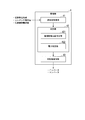
- FIG. 2 is a diagram showing a specific example of the functional configuration of the management unit 4 of the embodiment.
- the management unit 4 includes a CPU (Central Processing Unit), a memory, an auxiliary storage device, and the like connected by a bus, and executes a program.
- the management unit 4 functions as a device including a measurement value acquisition unit 41, a determination unit 42, and a compressor control unit 43 by executing a program.
- the measured value acquisition unit 41 acquires the power supply side current value, the capacitor voltage value, and the compressor side current value.
- the power supply side current value is a current value measured by the power supply side ammeter 34.
- the capacitor voltage value is a voltage value measured by the voltmeter 35.
- the compressor side current value is a current value measured by the compressor side ammeter 36.
- the determination unit 42 determines whether or not the power supply side current value or the compressor side power is equal to or higher than a predetermined value based on the power supply side current value, the capacitor voltage value, and the compressor side current value acquired by the measurement value acquisition unit 41. To do.
- the compressor side power is a value calculated based on the capacitor voltage value and the compressor side current value, and is a value having a dimension of power.
- the determination unit 42 includes a power supply side current value determination unit 421 and a power determination unit.
- the power supply side current value determination unit 421 acquires the power supply side current value acquired by the measurement value acquisition unit 41, and determines whether or not the power supply side current value exceeds a predetermined first value.
- the predetermined first value may be any value, for example, the maximum value of the current value of the current that can be passed by the control circuit 3.
- the predetermined first value may be, for example, a value lower than the maximum value of the current value of the current that can be passed by the control circuit 3 by a predetermined value.
- the electric power determination unit 422 acquires a value related to electric power (hereinafter referred to as “electric power-related value”) based on the capacitor voltage value and the compressor side current value acquired by the measured value acquisition unit 41.
- the power determination unit 422 determines whether or not the acquired power-related value exceeds a predetermined second value.
- Power-related values for example, may be a value P 1 calculated by the following equation (1).
- V out is a capacitor voltage value.
- I out is the current value on the compressor side.
- ⁇ sets I out ⁇ V out based on the power lost from the time the AC power supplied by the three-phase AC power supply 1 is applied to the control circuit 3 to the time it reaches the compressor 2. This is the correction value to be corrected.
- the correction value ⁇ is 1/1- ⁇ .
- ⁇ is the power value of the AC power supplied by the three-phase AC power supply 1 from the time it is applied to the control circuit 3 until it reaches the compressor 2, which is the AC power supplied by the three-phase AC power supply 1. It is a ratio to the power value.
- the power-related value may be, for example, a time average value (that is, electric energy) of (I out ⁇ V out ).
- the second value may be, for example, the power value of the AC power supplied by the three-phase AC power supply 1.
- the compressor control unit controls the compressor based on the determination result of the determination unit.
- FIG. 3 is a flowchart showing a specific processing flow in which the management unit 4 controls the compressor 2 in the embodiment.
- the measured value acquisition unit 41 acquires the input current value Iin measured by the power supply side ammeter 34 (step S101).
- the power supply side current value determination unit 421 determines whether or not the current value acquired in step S101 is larger than the first value (step S102). In step S102, when the current value is larger than the first value (step S102: YES), the compressor control unit 43 reduces the rotation speed of the electric motor 21 of the compressor 2 to a predetermined value (step S103).
- step S102 when the current value is equal to or less than the first value (step S102: NO), the measured value acquisition unit 41 acquires the capacitor voltage value (step S104). After step S104, the measured value acquisition unit 41 acquires the compressor side current value (step S105).
- the processing of step S104 and step S105 does not necessarily have to execute the processing of step S105 after the processing of step S104.
- the processing of step S104 and step S105 may be executed after the processing of step S105.
- the processing of step S104 and step S105 may be executed before the processing of step S102, for example.
- step S105 the power supply side current value determination unit 421 acquires the power-related value based on the capacitor voltage value and the compressor side current value (step S106).
- the power supply side current value determination unit 421 determines whether or not the power-related value is equal to or greater than the second value (step S107).
- step S107 when the power-related value is equal to or higher than the second value (step S107: YES), the compressor control unit 43 reduces the rotation speed of the electric motor 21 of the compressor 2 to a predetermined value (step S103).
- step S107 when the power-related value is less than the second value (step S107: NO), the management unit 4 ends the process.
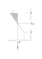
- FIG. 4 is a diagram showing an example of voltage fluctuation and power variation at the time of input current release of the compression device 100 of the embodiment.
- the input current release time is when the input current value Iin is larger than the first value.
- the horizontal axis of FIG. 4 represents the voltage supplied by the three-phase AC power supply 1.
- the vertical axis of FIG. 4 represents the electric power supplied to the electric motor 21.
- the electric motor 21 may be supplied with excessive power according to the power supplied by the three-phase AC power supply 1.
- the figure S represents the excess electric power supplied to the electric motor 21.
- FIG. S is an excessive power supplied to the electric motor 21 when the input current value Iin is equal to or less than the input current release point.
- the compression device 100 including the power supply side current value determination unit 421 can suppress the supply of excess power to the electric motor 21 due to fluctuations in the power supplied by the three-phase AC power supply 1.
- control circuit 3 and the management unit 4 which are control devices configured in this way include the power determination unit 422, the rotation speed of the electric motor 21 is controlled based on the electric power supplied from the inverter to the compressor 2. be able to. Therefore, when the voltage supplied by the three-phase AC power supply 1 is unbalanced and becomes higher than a predetermined value and the power consumption becomes large, the circuit loss (heat generation) of the control circuit of the converter or the inverter does not become too large. , It is possible to suppress an increase in the amount of heat generated by the electrical components incorporated in the control circuit 3.
- the control device can be inexpensive and of high quality. Furthermore, when the power supply voltage fluctuates and becomes higher than the standard, the power consumption increases. Even if the power consumption increases, it does not matter as long as the required cooling (heating) capacity is secured. In this case, it only follows the capacity control based on the detection result of the temperature sensor on the user side, but when the power consumption increases, the circuit loss (heat generation) of the control circuit of the converter or inverter increases, and the temperature upper limit of the controller parts Is to exceed.
- the upper limit of this temperature is defined as a value that should not be exceeded even for a moment in semiconductors, for example, and the magnet SW and electrolytic capacitor have a shorter life than the designed life.
- the power consumption is calculated from the DC voltage, the rotation speed of the compressor that is the load, and the current value.
- the power consumption is calculated from the DC voltage, the rotation speed of the compressor that is the load, and the current value.
- the compression device 100 configured in this way includes the power determination unit 422, 200V, 380V, 400V, 440V, etc. can be obtained by simply changing the second value without changing the control circuit 3. Can operate at different input voltages.
- the input voltage is a voltage applied to the control circuit 3 by the three-phase AC power supply 1. That is, the compression device 100 having the same hardware design can be used under different input voltages from 200V to 440V.
- the compression device 100 does not necessarily have to be used only under an input voltage in the range of 200V to 400V, and may be used at other input voltages (for example, 100V, 600V, etc.). Even in that case, the compression device 100 operates to include the power determination unit 422.
- the compression device 100 may be provided with one power supply side ammeter 34 or a plurality of power supply side ammeters 34 as long as the current value of the line current flowing between the three-phase AC power supply 1 and the converter 31 can be measured. Good.
- the compression device 100 may be provided with one voltmeter 35 or a plurality of voltmeters 35 as long as the voltage value of the voltage of the capacitor 32 can be measured.
- the compressor 100 may include one or a plurality of compressor-side ammeters 36 as long as the current value of the line current supplied by the inverter 33 to the compressor 2 can be measured.
- the compressor 100 configured in this way includes the power determination unit 422, the compressor 2 can be operated with an input voltage within the range of ⁇ 10% of the rated voltage of the compressor 2.
- each functional unit of the management unit 4 is a software functional unit, but it may be a hardware functional unit such as an LSI.
- the rotation speed of the electric motor 21 of the compressor 2 can be controlled based on the electric power supplied from the inverter 33 to the compressor 2. .. Therefore, even when the voltage supplied by the power supply is higher than a predetermined value, it is possible to suppress an increase in the amount of heat generated by the compressor 2 by lowering the rotation speed of the electric motor 21.
Landscapes
- Engineering & Computer Science (AREA)
- Power Engineering (AREA)
- Control Of Ac Motors In General (AREA)
- Inverter Devices (AREA)
- Control Of Electric Motors In General (AREA)
Abstract
Description
しかしながら、商用交流電源から供給される電力は電圧が安定しない場合があり、供給される電圧の電圧値が高くなると出力電力の電力値が必要以上に大きくなり、発熱量が増える場合があった。このような場合には電流レリース制御だけでは、電気部品の発熱量の増加を抑制することができず、電気部品の寿命短縮や故障の原因となっていた。
圧縮装置100は、3相交流電源1、圧縮機2、制御装置である制御回路3及び管理部4を備える。3相交流電源1は、制御回路3を介して圧縮機2の電動機21に電力を供給する。
コンデンサ32は、コンバータ31に並列に接続される。コンデンサ32は、コンバータ31が変換した直流電力によって供給される電力を蓄電する。
インバータ33は、コンバータ31及びコンデンサ32に並列に接続される。インバータ33は、コンバータ31が変換し出力した直流電力を所定の周波数の交流電力に変換し、変換後の交流電力を3相交流の交流方式によって圧縮機2に供給する。
電圧計35は、コンデンサ32の電圧の電圧値を測定する。
圧縮機側電流計36は、インバータ33が圧縮機2に供給する3相の電流の電流値(すなわち、インバータ33から圧縮機2に流れる線電流の電流値)を測定する。圧縮機側電流計36は、具体的には、3相のうちの2相に流れる電流を検出し、検出結果に基づいて2相のそれぞれに流れる電流の電流値を算出する。圧縮機側電流計36は、3相のうちの残りの1相に流れる電流値を、検出された2相に流れる電流の電流値に基づいて算出する。なお、圧縮機側電流計36が検出する電流が流れる3相とは、インバータ33と圧縮機2とを接続する3つの導線を意味する。なお圧縮機側電流計36が検出する電流が流れる3相のうちの2相とは、インバータ33と圧縮機2とを接続する3つの導線のうちの2つの導線を意味する。なお圧縮機側電流計36が検出する電流が流れる3相のうちの1相とは、インバータ33と圧縮機2とを接続する3つの導線のうちの1つの導線を意味する。
管理部4は、バスで接続されたCPU(Central Processing Unit)やメモリや補助記憶装置などを備え、プログラムを実行する。管理部4は、プログラムの実行によって、測定値取得部41、判定部42及び圧縮機制御部43を備える装置として機能する。
電源側電流値判定部421は、測定値取得部41が取得した電源側電流値を取得して、電源側電流値が予め定められた第一の値を超えるか否かを判定する。予め定められた第一の値は、どのような値であってもよく、例えば、制御回路3が流すことができる電流の電流値の最大値であってもよい。予め定められた第一の値は、例えば、制御回路3が流すことができる電流の電流値の最大値よりも所定の値だけ低い値であってもよい。
電力関係値は、例えば、以下の式(1)によって算出される値P1であってもよい。

測定値取得部41が、電源側電流計34が測定した入力電流値Iinを取得する(ステップS101)。電源側電流値判定部421が、ステップS101において取得された電流値が第一の値より大きいか否かを判定する(ステップS102)。ステップS102において、電流値が第一の値より大きい場合(ステップS102:YES)、圧縮機制御部43は、圧縮機2の電動機21の回転数を所定の値まで下げる(ステップS103)。
図4の横軸は3相交流電源1が供給する電圧を表す。図4の縦軸は、電動機21に供給される電力を表す。
入力電流値Iinが第一の値以下で、電源側電流値判定部421による判定が実行されない場合、入力電力は3相交流電源1が供給する電圧に線形に比例する。そのため、電源側電流値判定部421による判定が実行されない場合には、電動機21には、3相交流電源1が供給する電力に応じて過剰な電力が供給される場合がある。図4において図形Sが、電動機21に供給される過剰な電力を表す。
図形Sは、入力電流値Iinが入力電流レリース点以下の場合に、電動機21に供給される過剰な電力である。
第一の値が、入力電流レリース点の値である場合、電源側電流値判定部421によって、入力電流値Iinが入力電流レリース点以上になることがない。そのため、電源側電流値判定部421を備える圧縮装置100は、3相交流電源1が供給する電力の変動によって電動機21に過剰な電力が供給されることを抑制することができる。
さらに、電源電圧が変動して標準より高くなった場合に、消費電力が大きくなる。消費電力が大きくなっても、必要な冷却(加熱)能力が確保されていれば問題にならない。この場合、利用側温度センサの検知結果による能力制御に追従するのみだが、消費電力が大きくなった時に、コンバータやインバータの制御回路の回路ロス(発熱)が大きくなり、制御器の部品の温度上限を超えてしまうことである。
この温度の上限は例えば半導体は、一瞬たりとも超えてはならない値と規定されており、マグネットSWや電解コンデンサは設計した寿命よりも短くなる。これを防止するために、直流電圧と負荷となるコンプレッサの回転数、電流値で消費電力を計算する。消費電力を所定値以下に制御する事で、機器内の内部発熱を一定以下に抑えることができる。
また、これにともない圧縮機2への余剰なエネルギの入力も抑えることができるため、圧縮装置100は、圧縮機2の電動機21の回転数が必要以上に増大することがない。そのため、3相交流電源1が供給する電圧が所定の値よりも高い場合であっても、圧縮機2の発熱量の増大を抑制することができる。
なお、圧縮装置100は、必ずしも200V~400Vまでの範囲内の入力電圧の元でだけ使用される必要はなく、それ以外の入力電圧(例えば、100Vや600V等)で使用されてもよい。またその場合でも、電力判定部422を備えるために、圧縮装置100は動作する。
Claims (3)
- 交流電力を供給する交流電源と、
前記交流電源が供給する前記交流電力を直流電力に変換するコンバータと、
前記コンバータに接続され、前記コンバータが変換し出力した直流電力を交流電力に変換するインバータと、
前記インバータが変換した交流電力によって回転する電動機と、
前記コンバータから出力される電圧の電圧値と前記インバータが変換した交流電力の電流値とに基づいて前記電動機の回転数を制御する制御部と、
を備え、
前記制御部は、前記電圧値と前記電流値とによって算出される電力値が所定の値を超えた場合に、前記電動機の回転数を下げる、
電動機制御装置。 - 前記制御部は、前記交流電源が供給する電流の電流値が所定の値を超えた場合に、前記電動機の回転数を下げる、
請求項1に記載の電動機制御装置。 - 交流電力を供給する交流電源と、前記交流電源が供給する前記交流電力を直流電力に変換するコンバータと、前記コンバータに接続され、前記コンバータが変換し出力した直流電力を交流電力に変換するインバータと、前記インバータが変換した交流電力によって回転する電動機と、前記コンバータから出力される電圧の電圧値と前記インバータが変換した交流電力の電流値とに基づいて前記電動機の回転数を制御する制御部と、を備える電動機制御装置が行う制御方法であって、
前記制御部が、前記電圧値と前記電流値とによって算出される電力値が所定の値を超えた場合に、前記電動機の回転数を下げる制御ステップ、
を有する制御方法。
Priority Applications (2)
| Application Number | Priority Date | Filing Date | Title |
|---|---|---|---|
| KR1020217025909A KR20210113368A (ko) | 2019-03-18 | 2019-11-20 | 전동기 제어장치 및 제어 방법 |
| JP2021506146A JPWO2020188884A1 (ja) | 2019-03-18 | 2019-11-20 | 電動機制御装置および制御方法 |
Applications Claiming Priority (2)
| Application Number | Priority Date | Filing Date | Title |
|---|---|---|---|
| JP2019050048 | 2019-03-18 | ||
| JP2019-050048 | 2019-03-18 |
Publications (1)
| Publication Number | Publication Date |
|---|---|
| WO2020188884A1 true WO2020188884A1 (ja) | 2020-09-24 |
Family
ID=72520788
Family Applications (1)
| Application Number | Title | Priority Date | Filing Date |
|---|---|---|---|
| PCT/JP2019/045368 Ceased WO2020188884A1 (ja) | 2019-03-18 | 2019-11-20 | 電動機制御装置および制御方法 |
Country Status (3)
| Country | Link |
|---|---|
| JP (1) | JPWO2020188884A1 (ja) |
| KR (1) | KR20210113368A (ja) |
| WO (1) | WO2020188884A1 (ja) |
Citations (4)
| Publication number | Priority date | Publication date | Assignee | Title |
|---|---|---|---|---|
| JP2005039876A (ja) * | 2003-07-15 | 2005-02-10 | Matsushita Electric Ind Co Ltd | 組電池から電力を供給されるモータの出力制御方法 |
| JP2010233304A (ja) * | 2009-03-26 | 2010-10-14 | Mitsubishi Electric Corp | 直流電動機駆動用のインバータ制御装置 |
| JP2017028833A (ja) * | 2015-07-21 | 2017-02-02 | ファナック株式会社 | ヒートシンクの放熱性能の異常を検知するモータ駆動装置、および検知方法 |
| JP2017208979A (ja) * | 2016-05-20 | 2017-11-24 | 東芝キヤリア株式会社 | 電源装置 |
Family Cites Families (4)
| Publication number | Priority date | Publication date | Assignee | Title |
|---|---|---|---|---|
| JPH0626695A (ja) | 1992-07-07 | 1994-02-04 | Fujitsu General Ltd | 空気調和機の制御装置 |
| JP2002161886A (ja) * | 2000-11-27 | 2002-06-07 | Tsurumi Mfg Co Ltd | 水中電動ポンプの回転数制御における誤動作防止装置 |
| DE10393403T5 (de) * | 2003-06-25 | 2005-09-01 | Mitsubishi Denki K.K. | Energiespar-Effekt-Anzeigeeinheit in einem Inverter |
| JP5186586B2 (ja) * | 2011-09-01 | 2013-04-17 | 株式会社松井製作所 | 駆動制御装置、電気機器及び駆動制御方法 |
-
2019
- 2019-11-20 JP JP2021506146A patent/JPWO2020188884A1/ja active Pending
- 2019-11-20 KR KR1020217025909A patent/KR20210113368A/ko not_active Ceased
- 2019-11-20 WO PCT/JP2019/045368 patent/WO2020188884A1/ja not_active Ceased
Patent Citations (4)
| Publication number | Priority date | Publication date | Assignee | Title |
|---|---|---|---|---|
| JP2005039876A (ja) * | 2003-07-15 | 2005-02-10 | Matsushita Electric Ind Co Ltd | 組電池から電力を供給されるモータの出力制御方法 |
| JP2010233304A (ja) * | 2009-03-26 | 2010-10-14 | Mitsubishi Electric Corp | 直流電動機駆動用のインバータ制御装置 |
| JP2017028833A (ja) * | 2015-07-21 | 2017-02-02 | ファナック株式会社 | ヒートシンクの放熱性能の異常を検知するモータ駆動装置、および検知方法 |
| JP2017208979A (ja) * | 2016-05-20 | 2017-11-24 | 東芝キヤリア株式会社 | 電源装置 |
Also Published As
| Publication number | Publication date |
|---|---|
| JPWO2020188884A1 (ja) | 2021-11-18 |
| KR20210113368A (ko) | 2021-09-15 |
Similar Documents
| Publication | Publication Date | Title |
|---|---|---|
| CN104040441B (zh) | 用于在可调节速度驱动器中检测相位损耗并且诊断dc链路电容器健康的系统和方法 | |
| KR101542435B1 (ko) | Ups의 동작을 컨트롤하는 시스템 및 방법 | |
| US9673743B1 (en) | Efficient motor control | |
| CN111999642B (zh) | 一种电机功率密度测试装置及方法 | |
| KR101496859B1 (ko) | 조정가능한 ups용 배터리 충전기 | |
| CN105830326B (zh) | 用于确定转换器单元中的单元电容器劣化的方法和功率转换器 | |
| CN107154771B (zh) | 用于电力电子变换器的风机变频调速系统 | |
| BRPI1013882B1 (pt) | Dispositivo para carregar uma bateria, e, método de carregar uma bateria | |
| US10033189B2 (en) | Operation control apparatus for solar power system | |
| JP6121671B2 (ja) | 高調波計測方法および高調波計測装置 | |
| CN113615028B (zh) | 控制装置、系统、控制方法以及计算机程序产品 | |
| CN111492253A (zh) | 电压不平衡判断方法和电力转换装置 | |
| CN105431996B (zh) | 不间断电源控制 | |
| CN111917277A (zh) | 供电装置 | |
| JP5328262B2 (ja) | オゾン発生装置 | |
| CN119137828A (zh) | 燃料电池设备及其方法 | |
| WO2020188884A1 (ja) | 電動機制御装置および制御方法 | |
| JP7573273B2 (ja) | Lclフィルタ寿命診断装置及びlclフィルタ寿命診断方法 | |
| JP6172868B2 (ja) | 電源装置 | |
| Hermawan et al. | Effect of the placement capacitor bank on electrical power quality in the ILST fan drive system | |
| WO2018049074A1 (en) | Efficient induction motor control | |
| JP2005045914A (ja) | インバータ装置 | |
| JP6743522B2 (ja) | 電力供給システム及び電力供給方法 | |
| KR101618444B1 (ko) | 차량용 발전계통 과부하시 전력변환장치의 출력전압 조정방법 | |
| JP5188536B2 (ja) | 電源検査装置、電源検査方法、電源装置 |
Legal Events
| Date | Code | Title | Description |
|---|---|---|---|
| 121 | Ep: the epo has been informed by wipo that ep was designated in this application |
Ref document number: 19919716 Country of ref document: EP Kind code of ref document: A1 |
|
| ENP | Entry into the national phase |
Ref document number: 2021506146 Country of ref document: JP Kind code of ref document: A |
|
| ENP | Entry into the national phase |
Ref document number: 20217025909 Country of ref document: KR Kind code of ref document: A |
|
| NENP | Non-entry into the national phase |
Ref country code: DE |
|
| 122 | Ep: pct application non-entry in european phase |
Ref document number: 19919716 Country of ref document: EP Kind code of ref document: A1 |