WO2020188858A1 - 液冷ジャケットの製造方法 - Google Patents
液冷ジャケットの製造方法 Download PDFInfo
- Publication number
- WO2020188858A1 WO2020188858A1 PCT/JP2019/036042 JP2019036042W WO2020188858A1 WO 2020188858 A1 WO2020188858 A1 WO 2020188858A1 JP 2019036042 W JP2019036042 W JP 2019036042W WO 2020188858 A1 WO2020188858 A1 WO 2020188858A1
- Authority
- WO
- WIPO (PCT)
- Prior art keywords
- jacket
- sealing body
- side pin
- end side
- pin
- Prior art date
- Legal status (The legal status is an assumption and is not a legal conclusion. Google has not performed a legal analysis and makes no representation as to the accuracy of the status listed.)
- Ceased
Links
Images













Classifications
-
- B—PERFORMING OPERATIONS; TRANSPORTING
- B23—MACHINE TOOLS; METAL-WORKING NOT OTHERWISE PROVIDED FOR
- B23K—SOLDERING OR UNSOLDERING; WELDING; CLADDING OR PLATING BY SOLDERING OR WELDING; CUTTING BY APPLYING HEAT LOCALLY, e.g. FLAME CUTTING; WORKING BY LASER BEAM
- B23K20/00—Non-electric welding by applying impact or other pressure, with or without the application of heat, e.g. cladding or plating
- B23K20/12—Non-electric welding by applying impact or other pressure, with or without the application of heat, e.g. cladding or plating the heat being generated by friction; Friction welding
Definitions
- the present invention relates to a method for manufacturing a liquid-cooled jacket.
- Patent Document 1 discloses a method for manufacturing a liquid-cooled jacket.
- FIG. 34 is a cross-sectional view showing a conventional method for manufacturing a liquid-cooled jacket.
- the butt portion J10 formed by abutting the step side surface 101c provided on the step portion of the aluminum alloy jacket body 101 and the side surface 102c of the aluminum alloy sealing body 102. This is to perform friction stir welding.
- the connecting portion F41 of the rotating tool F40 is separated and only the stirring pin F42 is inserted into the butt portion J10 to perform friction stir welding.
- the rotation center axis Z of the rotation tool F40 is overlapped with the butt portion J10 and relatively moved.
- the jacket body 101 tends to have a complicated shape.
- a jacket body 101 formed of a cast material of 4000 series aluminum alloy and a relatively simple shape such as a sealing body 102 is a wrought material of 1000 series aluminum alloy. In some cases, it is formed by. In this way, a liquid-cooled jacket may be manufactured by joining members of different grades of aluminum alloy.
- the jacket body 101 generally has a higher hardness than the sealing body 102. Therefore, when friction stir welding is performed as shown in FIG. 34, the stirring pin F42 becomes the sealing body 102.
- the material resistance received from the jacket body 101 side is larger than the material resistance received from the side.
- the present invention is composed of a jacket body having a bottom portion and a peripheral wall portion rising from the peripheral edge of the bottom portion, and a sealing body for sealing the opening of the jacket body. It is a method of manufacturing a liquid-cooled jacket in which the sealing body is joined by frictional stirring.
- the jacket body is made of a first aluminum alloy
- the sealing body is made of a second aluminum alloy.
- the first aluminum alloy is a grade having a higher hardness than the second aluminum alloy
- the rotation tool used for friction stirring includes a base end side pin and a tip end side pin
- the taper angle of the base end side pin is It is larger than the taper angle of the tip end side pin
- a stepped pin step portion is formed on the outer peripheral surface of the base end side pin, and by placing the sealing body on the jacket body.
- the outer peripheral surface of the side pin is slightly in contact with the end surface of the peripheral wall portion, and the outer peripheral surface of the base end side pin is in contact with the side surface of the sealing body, and the outer peripheral surface is set closer to the sealing body than the butt portion.
- the tip that rotates in the main joining step includes a main joining step of circling around the side surface of the sealing body at a predetermined depth along a set movement route and frictionally stirring the butt portion. After inserting the side pin into the start position set on the surface side of the sealing body further than the set movement route, the predetermined rotation tool is moved to a position overlapping the set movement route. The tip side pin is gradually pushed in until the depth is reached.
- the present invention is composed of a jacket body having a bottom portion and a peripheral wall portion rising from the peripheral edge of the bottom portion, and a sealing body that seals an opening of the jacket body, and the jacket body and the sealing body are formed.
- a method for manufacturing a liquid-cooled jacket to be joined by frictional stirring wherein the jacket body is made of a first aluminum alloy, the sealing body is made of a second aluminum alloy, and the first aluminum alloy is
- the rotation tool used for friction stirring which is a grade having a higher hardness than the second aluminum alloy, includes a base end side pin and a tip end side pin, and the taper angle of the base end side pin is the taper of the tip end side pin.
- a stepped pin step portion is formed on the outer peripheral surface of the base end side pin, and by placing the sealing body on the jacket body, the end surface of the peripheral wall portion is formed.
- the start position set on the set movement route in the main joining step includes a main joining step of circling around the side surface of the sealing body at a predetermined depth along the line and rubbing and stirring the butt portion. It is characterized in that the tip side pin is inserted from the above, and the tip side pin is gradually pushed in until the predetermined depth is reached while moving in the traveling direction.
- the second aluminum alloy mainly on the sealing body side of the butt portion is agitated and plastically fluidized by the frictional heat between the sealing body and the tip side pin, and the peripheral wall portion and the sealing body are formed at the butt portion. Can be joined. Further, since the outer peripheral surface of the tip side pin is kept in contact with the peripheral wall portion of the jacket body slightly, it is possible to minimize the mixing of the first aluminum alloy from the jacket body to the sealing body. As a result, the second aluminum alloy on the sealing body side is mainly frictionally agitated at the butt portion, so that a decrease in joint strength can be suppressed.
- the rotation center axis of the rotation tool toward the sealing body so that the outer peripheral surface of the tip side pin and the end surface of the peripheral wall portion are parallel to each other.
- the tip side pin and the peripheral wall portion can be brought into contact with each other in a well-balanced manner.
- the rotation tool is rotated at a predetermined rotation speed to perform frictional stirring, and when the tip end side pin is inserted in the main joining step, the rotation speed is higher than the predetermined rotation speed. It is preferable to insert the pin on the tip side in a rotated state and move it to the set movement route while gradually reducing the rotation speed.
- friction stir welding can be performed more preferably.
- the jacket body and the sealing body so that the side surface of the sealing body is on the outer side of the side surface of the jacket body.
- the present invention is composed of a jacket body having a bottom portion and a peripheral wall portion rising from the peripheral edge of the bottom portion, and a sealing body for sealing the opening of the jacket body, and the jacket body and the sealing body are formed.
- a method for manufacturing a liquid-cooled jacket to be joined by frictional stirring The jacket body is made of a second aluminum alloy, the sealant is made of a first aluminum alloy, and the first aluminum alloy is
- the rotation tool used for friction stirring which is a grade having a higher hardness than the second aluminum alloy, includes a base end side pin and a tip end side pin, and the taper angle of the base end side pin is the taper of the tip end side pin.
- a stepped pin step portion is formed on the outer peripheral surface of the base end side pin, and by placing the sealing body on the jacket body, the end surface of the peripheral wall portion is formed.
- the rotating tip side pin is moved from the set movement route. Further, after inserting the jacket body into the set start position on the bottom surface side, the tip side pin is moved until the predetermined depth is reached while moving the rotation center axis of the rotation tool to a position overlapping the set movement route. It is characterized by gradually pushing in.
- the present invention is composed of a jacket body having a bottom portion and a peripheral wall portion rising from the peripheral edge of the bottom portion, and a sealing body for sealing the opening of the jacket body, and the jacket body and the sealing body are formed.
- a method for manufacturing a liquid-cooled jacket to be joined by frictional stirring The jacket body is made of a second aluminum alloy, the sealant is made of a first aluminum alloy, and the first aluminum alloy is
- the rotation tool used for friction stirring which is a grade having a higher hardness than the second aluminum alloy, includes a base end side pin and a tip end side pin, and the taper angle of the base end side pin is the taper of the tip end side pin.
- a stepped pin step portion is formed on the outer peripheral surface of the base end side pin, and by placing the sealing body on the jacket body, the end surface of the peripheral wall portion is formed.
- the tip side pin is inserted, and the tip side pin is gradually pushed in until the predetermined depth is reached while moving in the traveling direction.
- the second aluminum alloy mainly on the jacket body side of the butt portion is agitated and plastically fluidized by the frictional heat between the jacket body and the tip side pin, and the peripheral wall portion and the sealing body are joined at the butt portion. can do. Further, since the outer peripheral surface of the tip side pin is kept in contact with the sealing body slightly, it is possible to minimize the mixing of the first aluminum alloy from the sealing body into the jacket body. As a result, the second aluminum alloy on the jacket body side is mainly frictionally agitated at the butt portion, so that a decrease in joint strength can be suppressed. Further, by gradually pushing the tip side pin until it reaches a predetermined depth while moving the rotation tool, it is possible to prevent the frictional heat from becoming excessive locally.
- the main joining step it is preferable to incline the rotation center axis of the rotation tool toward the jacket body so that the outer peripheral surface of the tip side pin and the back surface of the sealing body are parallel to each other.
- the tip side pin and the sealing body can be brought into contact with each other in a well-balanced manner.
- the rotation tool is rotated at a predetermined rotation speed to perform frictional stirring, and when the tip end side pin is inserted in the main joining step, the rotation speed is higher than the predetermined rotation speed. It is preferable to insert the pin on the tip side in a rotated state and move it to the set movement route while gradually reducing the rotation speed.
- friction stir welding can be performed more preferably.
- the jacket body and the sealing body so that the side surface of the jacket body is on the outer side of the side surface of the sealing body.
- the present invention is composed of a jacket body having a bottom portion and a peripheral wall portion rising from the peripheral edge of the bottom portion, and a sealing body for sealing the opening of the jacket body.
- the jacket body is made of a first aluminum alloy
- the sealing body is made of a second aluminum alloy.
- the first aluminum alloy is a grade having a higher hardness than the second aluminum alloy
- the rotary tool used for friction stir welding includes a base end side pin and a tip end side pin
- the taper angle of the base end side pin is It is larger than the taper angle of the tip end side pin
- a stepped pin step portion is formed on the outer peripheral surface of the base end side pin
- the sealing body is placed on the jacket body.
- the set moving route includes a main joining step of circling around the side surface of the sealing body at a predetermined depth along the set movement route and frictionally agitating the butt portion.
- the end position is set on the surface side of the sealing body, and after friction stir welding with respect to the butt portion, the tip side pin is gradually raised while moving the rotation tool to the end position to reach the end position. It is characterized in that the rotating tool is detached from the sealing body.
- the present invention is composed of a jacket body having a bottom portion and a peripheral wall portion rising from the peripheral edge of the bottom portion, and a sealing body for sealing the opening of the jacket body, and the jacket body and the sealing body are formed.
- a method for manufacturing a liquid-cooled jacket that is joined by friction stir welding is made of a first aluminum alloy
- the sealant is made of a second aluminum alloy
- the first aluminum alloy is A grade having a higher hardness than the second aluminum alloy
- the rotary tool used for friction stir welding includes a base end side pin and a tip end side pin
- the taper angle of the base end side pin is the taper of the tip end side pin.
- the angle is larger than the angle, and a stepped pin step portion is formed on the outer peripheral surface of the base end side pin, and by placing the sealing body on the jacket body, the end surface of the peripheral wall portion is formed.
- the end position is set on the set movement route, which includes a main joining step of circling around the side surface of the sealing body at a predetermined depth and frictionally agitating the butt portion. Then, after friction stir welding with respect to the butt portion, the rotary tool is gradually raised while moving the rotary tool to the end position, and the rotary tool is separated from the sealing body at the end position. And.
- the second aluminum alloy mainly on the sealing body side of the butt portion is agitated and plastically fluidized by the frictional heat between the sealing body and the tip side pin, and the peripheral wall portion and the sealing body are formed at the butt portion. Can be joined. Further, since the outer peripheral surface of the tip side pin is kept in contact with the peripheral wall portion of the jacket body slightly, it is possible to minimize the mixing of the first aluminum alloy from the jacket body to the sealing body. As a result, the second aluminum alloy on the sealing body side is mainly frictionally agitated at the butt portion, so that a decrease in joint strength can be suppressed. Further, by gradually removing the tip side pin while moving the rotation tool, it is possible to prevent the frictional heat from becoming excessive locally.
- the rotation center axis of the rotation tool toward the sealing body so that the outer peripheral surface of the tip side pin and the end surface of the peripheral wall portion are parallel to each other.
- the tip side pin and the peripheral wall portion can be brought into contact with each other in a well-balanced manner.
- the rotation tool is rotated at a predetermined rotation speed to perform frictional stirring, and when the tip end side pin is separated in the main joining step, the rotation speed is gradually higher than the predetermined rotation speed. It is preferable to move to the end position while raising.
- friction stir welding can be performed more preferably.
- the jacket body and the sealing body so that the side surface of the sealing body is on the outer side of the side surface of the jacket body.
- the present invention is composed of a jacket body having a bottom portion and a peripheral wall portion rising from the peripheral edge of the bottom portion, and a sealing body for sealing the opening of the jacket body, and the jacket body and the sealing body are formed.
- a method for manufacturing a liquid-cooled jacket that is joined by friction stir welding The jacket body is made of a second aluminum alloy, the sealant is made of a first aluminum alloy, and the first aluminum alloy is A grade having a higher hardness than the second aluminum alloy, the rotary tool used for friction stir welding includes a base end side pin and a tip end side pin, and the taper angle of the base end side pin is the taper of the tip end side pin.
- a stepped pin step portion is formed on the outer peripheral surface of the base end side pin, and by placing the sealing body on the jacket body, the end surface of the peripheral wall portion is formed.
- the bottom surface side of the jacket body is closer to the set movement route, including a main joining step of circling around the side surface of the jacket body at a predetermined depth and frictionally agitating the butt portion.
- the end position is set to, the tip side pin is gradually raised while moving the rotation tool to the end position, and the rotation tool is separated from the jacket body at the end position. It is characterized by letting it.
- the present invention is composed of a jacket body having a bottom portion and a peripheral wall portion rising from the peripheral edge of the bottom portion, and a sealing body for sealing the opening of the jacket body, and the jacket body and the sealing body are formed.
- a method for manufacturing a liquid-cooled jacket that is joined by friction stir welding The jacket body is made of a second aluminum alloy, the sealant is made of a first aluminum alloy, and the first aluminum alloy is A grade having a higher hardness than the second aluminum alloy, the rotary tool used for friction stir welding includes a base end side pin and a tip end side pin, and the taper angle of the base end side pin is the taper of the tip end side pin.
- the angle is larger than the angle, and a stepped step portion is formed on the outer peripheral surface of the base end side pin.
- the end position is set on the set movement route, and the end position is set in the main joining step, which includes a main joining step of circling around the side surface of the jacket body at a predetermined depth and frictionally stirring the butt portion.
- the rotary tool is moved to the end position and the tip end side pin is gradually raised to separate the rotary tool from the jacket body at the end position.
- the second aluminum alloy mainly on the jacket body side of the butt portion is agitated and plastically fluidized by the frictional heat between the jacket body and the tip side pin, and the peripheral wall portion and the sealing body are joined at the butt portion. can do. Further, since the outer peripheral surface of the tip side pin is kept in contact with the sealing body slightly, it is possible to minimize the mixing of the first aluminum alloy from the sealing body into the jacket body. As a result, the second aluminum alloy on the jacket body side is mainly frictionally agitated at the butt portion, so that a decrease in joint strength can be suppressed. Further, by gradually removing the tip side pin while moving the rotation tool, it is possible to prevent the frictional heat from becoming excessive locally.
- the main joining step it is preferable to incline the rotation center axis of the rotation tool toward the jacket body so that the outer peripheral surface of the tip side pin and the back surface of the sealing body are parallel to each other.
- the tip side pin and the sealing body can be brought into contact with each other in a well-balanced manner.
- the rotation tool is rotated at a predetermined rotation speed to perform frictional stirring, and when the tip end side pin is separated in the main joining step, the rotation speed is gradually higher than the predetermined rotation speed. It is preferable to move to the end position while raising.
- friction stir welding can be performed more preferably.
- the jacket body and the sealing body so that the side surface of the jacket body is on the outer side of the side surface of the sealing body.
- the present invention is composed of a jacket body having a bottom portion and a peripheral wall portion rising from the peripheral edge of the bottom portion, and a sealing body for sealing the opening of the jacket body.
- a method for manufacturing a liquid-cooled jacket in which the sealing body is joined by friction stir welding is made of a first aluminum alloy, and the sealing body is made of a second aluminum alloy.
- the first aluminum alloy is a grade having a higher hardness than the second aluminum alloy, and the end surface of the peripheral wall portion is an inclined surface having a downward slope toward the side surface of the jacket body, and is used for friction stir welding.
- the rotation tool includes a base end side pin and a tip end side pin, and the taper angle of the base end side pin is larger than the taper angle of the tip end side pin, and a staircase is formed on the outer peripheral surface of the base end side pin.
- a stepped portion is formed, and by placing the sealing body on the jacket body, the end surface of the peripheral wall portion and the back surface of the sealing body are overlapped with each other, and a gap having a V-shaped cross section is formed in the butt portion.
- the tip side pin of the rotating tool is inserted into the side surface of the sealing body, and the outer peripheral surface of the tip side pin is slightly brought into contact with the inclined surface of the peripheral wall portion.
- the second aluminum alloy is allowed to flow into the gap, and the setting movement set to the sealing body side with respect to the butt portion. It is characterized by including a main joining step of circling around the side surface of the sealing body at a predetermined depth along the route and frictionally agitating the butt portion.
- the second aluminum alloy mainly on the sealing body side of the butt portion is agitated and plastically fluidized by the frictional heat between the sealing body and the stirring pin, and the peripheral wall portion and the sealing body are joined at the butt portion. can do. Further, since the outer peripheral surface of the stirring pin is kept in contact with the peripheral wall portion of the jacket body slightly, it is possible to minimize the mixing of the first aluminum alloy from the jacket body to the sealing body. As a result, the second aluminum alloy on the sealing body side is mainly frictionally agitated at the butt portion, so that a decrease in joint strength can be suppressed.
- burrs can be suppressed by bringing the outer peripheral surface of the base end side pin into contact with the sealing body to press the plastic fluid material. Further, by providing an inclined surface on the end surface of the peripheral wall portion, the contact allowance between the peripheral wall portion and the rotation tool can be reduced.
- the jacket body and the sealing body so that the side surface of the sealing body is on the outer side of the side surface of the jacket body.
- the present invention is composed of a jacket body having a bottom portion and a peripheral wall portion rising from the peripheral edge of the bottom portion, and a sealing body for sealing the opening of the jacket body, and the jacket body and the sealing body are formed.
- the jacket body is made of a second aluminum alloy
- the sealant is made of a first aluminum alloy
- the first aluminum alloy is It is a grade having a higher hardness than the second aluminum alloy
- the peripheral edge of the back surface of the sealing body is an inclined surface so that the plate thickness decreases toward the side surface of the sealing body, and friction stir welding
- the rotation tool used in is provided with a base end side pin and a tip end side pin, and the taper angle of the base end side pin is larger than the taper angle of the tip end side pin, and is formed on the outer peripheral surface of the base end side pin.
- the tip-side pin of the rotating tool is inserted into the side surface of the jacket body, and the outer peripheral surface of the tip-side pin is slightly in contact with the inclined surface of the sealant.
- the setting is set to be closer to the jacket body than the butt portion while allowing the second aluminum alloy to flow into the gap in a state where the outer peripheral surface of the base end side pin is in contact with the side surface of the jacket body. It is characterized by including a main joining step of circling around the side surface of the jacket body at a predetermined depth along a moving route and frictionally agitating the butt portion.
- the second aluminum alloy mainly on the jacket body side of the butt portion is agitated and plastically fluidized by the frictional heat between the jacket body and the stirring pin, and the peripheral wall portion and the sealing body are joined at the butt portion. be able to.
- the outer peripheral surface of the stirring pin is kept in contact with the sealing body slightly, it is possible to minimize the mixing of the first aluminum alloy from the sealing body into the jacket body.
- the second aluminum alloy on the jacket body side is mainly frictionally agitated at the butt portion, so that a decrease in joint strength can be suppressed.
- the generation of burrs can be suppressed by bringing the outer peripheral surface of the base end side pin into contact with the jacket body and pressing the plastic fluid material.
- the contact allowance between the sealing body and the rotating tool can be reduced.
- the jacket body and the sealing body are formed so that the side surface of the jacket body is on the outer side of the side surface of the sealing body.
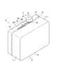
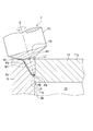
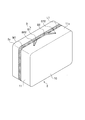
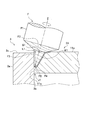
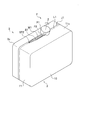
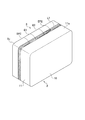
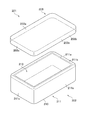
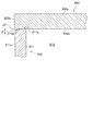
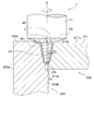
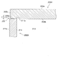
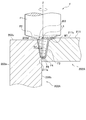
- FIG. 1 It is a perspective view which shows the main joining process of the manufacturing method of the liquid-cooled jacket which concerns on 1st Embodiment. It is sectional drawing which looked at the start position in this joining process which concerns on 1st Embodiment from the side. It is sectional drawing which saw the closet section in this joining process which concerns on 1st Embodiment from the side. It is sectional drawing which looked at the vicinity of the intermediate point S1 in this joining process which concerns on 1st Embodiment from the rear in the traveling direction. It is a perspective view which shows after the completion in this joining process which concerns on 1st Embodiment. It is sectional drawing which looked at the detachment section in this joining process which concerns on 1st Embodiment from the side. FIG.
- FIG. 5 is a cross-sectional view of the vicinity of the intermediate point S1 in the main joining step according to the modified example of the first embodiment as viewed from the rear in the traveling direction. It is a perspective view which shows this joining process in the manufacturing method of the liquid-cooled jacket which concerns on 2nd Embodiment of this invention. It is sectional drawing which looked at the closet section in this joining process which concerns on 2nd Embodiment from the side. It is sectional drawing which looked at the vicinity of the intermediate point S1 in this joining process which concerns on 2nd Embodiment from the rear in the traveling direction. It is a perspective view which shows after the completion in this joining process which concerns on 2nd Embodiment.
- the rotary tool is a tool used for friction stir welding.
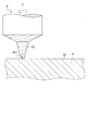
- the rotary tool F is made of, for example, tool steel, and is mainly composed of a base shaft portion F1, a base end side pin F2, and a tip end side pin F3.
- the base shaft portion F1 has a columnar shape and is a portion connected to the main shaft of the friction stir welder.
- the base end side pin F2 is continuous with the base shaft portion F1 and is tapered toward the tip end.
- the proximal end side pin F2 has a truncated cone shape.
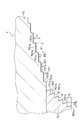
- the taper angle A of the base end side pin F2 may be appropriately set, but is, for example, 135 to 160 °. If the taper angle A is less than 135 ° or exceeds 160 °, the joint surface roughness after friction stir welding becomes large.
- the taper angle A is larger than the taper angle B of the tip side pin F3 described later.
- a stepped pin step portion F21 is formed on the outer peripheral surface of the base end side pin F2 over the entire height direction.
- the pin step portion F21 is formed in a clockwise or counterclockwise spiral shape.
- the pin step portion F21 has a spiral shape when viewed in a plane and a step shape when viewed from a side surface.
- the pin step portion F21 in order to rotate the rotation tool F counterclockwise, is set clockwise from the base end side to the tip end side.
- the pin step portion F21 is composed of a step bottom surface F21a and a step side surface F21b.
- the distance X1 (horizontal distance) between the vertices F21c and F21c of the adjacent pin step portions F21 is appropriately set according to the step angle C and the height Y1 of the step side surface F21b described later.
- the height Y1 of the step side surface F21b may be appropriately set, but is set to, for example, 0.1 to 0.4 mm. If the height Y1 is less than 0.1 mm, the joint surface roughness becomes large. On the other hand, when the height Y1 exceeds 0.4 mm, the joint surface roughness tends to increase, and the number of effective step portions (the number of pin step portions F21 in contact with the metal member to be joined) also decreases.
- the step angle C formed by the step bottom surface F21a and the step side surface F21b may be appropriately set, but is set to, for example, 85 to 120 °.
- the step bottom surface F21a is parallel to the horizontal plane in this embodiment.
- the step bottom surface F21a may be inclined in the range of -5 ° to 15 ° with respect to the horizontal plane from the rotation axis of the tool toward the outer peripheral direction (minus is downward with respect to the horizontal plane, plus is with respect to the horizontal plane).
- the distance X1, the height Y1 of the step side surface F21b, the step angle C, and the angle of the step bottom surface F21a with respect to the horizontal plane are such that the plastic fluid does not stay inside the pin step portion F21 and adhere to the outside during friction stir welding. It is appropriately set so that the joint surface roughness can be reduced by pressing the plastic fluid material with the step bottom surface F21a.
- the distal end side pin F3 is continuously formed on the proximal end side pin F2.
- the tip side pin F3 has a truncated cone shape.
- the tip of the tip side pin F3 is a flat surface F4 perpendicular to the rotation axis.
- the taper angle B of the tip end side pin F3 is smaller than the taper angle A of the base end side pin F2.
- a spiral groove F31 is engraved on the outer peripheral surface of the tip end side pin F3.
- the spiral groove F31 may be clockwise or counterclockwise, but in the first embodiment, the spiral groove F31 is carved clockwise from the proximal end side to the distal end side in order to rotate the rotating tool F counterclockwise.
- the spiral groove F31 is composed of a spiral bottom surface F31a and a spiral side surface F31b.
- the distance (horizontal distance) between the vertices F31c and F31c of the adjacent spiral grooves F31 is defined as the length X2.
- the height of the spiral side surface F31b is defined as the height Y2.
- the spiral angle D composed of the spiral bottom surface F31a and the spiral side surface F31b is formed at, for example, 45 to 90 °.
- the spiral groove F31 has a role of increasing frictional heat by coming into contact with the metal member to be joined and guiding the plastic fluid material to the tip side.
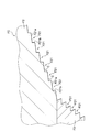
- FIG. 3 is a side view showing a first modification of the rotation tool of the present invention.
- the step angle C formed by the step bottom surface F21a of the pin step portion F21 and the step side surface F21b is 85 °.
- the step bottom surface F21a is parallel to the horizontal plane.
- the step bottom surface F21a is parallel to the horizontal plane, and the step angle C may be an acute angle within a range in which the plastic fluid material stays in the pin step portion F21 during friction stir welding and escapes to the outside without adhering. ..
- FIG. 4 is a side view showing a second modification of the rotation tool of the present invention.
- the step angle C of the pin step portion F21 is 115 °.
- the step bottom surface F21a is parallel to the horizontal plane.
- the step bottom surface F21a is parallel to the horizontal plane, and the step angle C may be an obtuse angle within the range of functioning as the pin step portion F21.
- FIG. 5 is a side view showing a third modification of the rotation tool of the present invention.
- the step bottom surface F21a is inclined 10 ° upward with respect to the horizontal plane from the rotation axis of the tool toward the outer peripheral direction.
- the step side surface F21b is parallel to the vertical surface.
- the step bottom surface F21a may be formed so as to incline upward from the horizontal plane from the rotation axis of the tool toward the outer peripheral direction within a range in which the plastic fluid material can be pressed during friction stir welding.
- the same effect as that of the following embodiment can be obtained by the first to third modifications of the rotation tool.
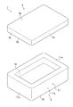
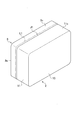
- the liquid-cooled jacket 1 is composed of a jacket body 2 and a sealing body 3.
- the liquid-cooled jacket 1 is a device that circulates a fluid inside to cool a heating element arranged therein.
- the jacket body 2 and the sealing body 3 are integrated by friction stir welding.
- the "front surface” means the surface opposite to the "back surface”.
- the jacket body 2 is mainly composed of a bottom portion 10 and a peripheral wall portion 11.
- the jacket body 2 is formed mainly containing a first aluminum alloy.
- a first aluminum alloy for example, an aluminum alloy casting material such as JISH5302 ADC12 (Al—Si—Cu system) is used.
- the bottom portion 10 is a plate-shaped member having a rectangular shape.
- the peripheral wall portion 11 is a wall portion that rises in a rectangular frame shape from the peripheral edge portion of the bottom portion 10. The corners of the peripheral wall portion 11 may be right angles, but in the present embodiment, round chamfering is performed.
- a recess 13 is formed in the bottom portion 10 and the peripheral wall portion 11.
- the jacket body 2 of the present embodiment is integrally formed, for example, the peripheral wall portion 11 may be divided and joined by a seal member to be integrated.
- the sealing body 3 is a plate-shaped member that seals the opening of the jacket body 2.
- the corners of the sealing body 3 may be right angles, but in the present embodiment, round chamfering is performed.
- the sealing body 3 is not particularly limited as long as it is a metal capable of friction stir welding, but in the present embodiment, it is formed mainly containing a second aluminum alloy.
- the second aluminum alloy is a material having a lower hardness than the first aluminum alloy.
- the second aluminum alloy is formed of, for example, an aluminum alloy wrought material such as JIS A1050, A1100, A6063.
- a preparation step, a mounting step, and a main joining step are performed.
- the preparation process is a process of preparing the jacket body 2 and the sealing body 3.
- the jacket body 2 and the sealing body 3 are not particularly limited in terms of manufacturing method, but the jacket body 2 is molded by die casting, for example.
- the sealing body 3 is formed by, for example, extrusion molding.
- the mounting step is a step of mounting the sealing body 3 on the jacket body 2.
- the end surface 11a of the peripheral wall portion 11 and the back surface 3b of the sealing body 3 are abutted to form the abutting portion J1.
- the butt portion J1 is formed in a rectangular shape in a plan view along the periphery of the sealing body 3.
- the side surface 11c of the peripheral wall portion 11 and the side surface 3c of the sealing body 3 are flush with each other.
- the jacket body 2 and the sealing body 3 may be temporarily joined by welding, friction stir welding, or the like.
- this joining step is a step of friction stir welding of the butt portion J1 using the rotary tool F.
- the "set movement route L1" (dashed line) is set on the surface 3a side of the sealing body 3 with respect to the butt portion J1.
- the set movement route L1 is a movement route of the rotation tool F necessary for joining the butt portion J1 in the main joining step described later.
- the set movement route L1 will be described in detail later.
- Three sections of the detachment section from to the end position EP1 are continuously friction-stir welded.
- the intermediate points S1 and S2 are set on the set movement route L1.
- the start position SP1 is set on the side surface 3c of the sealing body 3 on the surface 3a side of the sealing body 3 with respect to the set movement route L1.
- the angle formed by the line segment connecting the start position SP1 and the intermediate point S1 and the set movement route L1 is set to an obtuse angle.
- the rotation center axis Z of the rotation tool F is gradually tilted toward the sealing body 3 when viewed from the rear in the traveling direction (see FIG. 12), and is an intermediate point.
- the outer peripheral surface of the tip side pin F3 and the end surface 11a of the peripheral wall portion 11 are set to be parallel.
- the intermediate point S1 is reached, the outer peripheral surface of the front end side pin F3 and the end surface 11a of the peripheral wall portion 11 are set to slightly contact each other.
- the outer peripheral surface of the base end side pin F2 and the side surface 3c of the sealing body 3 are set to be in contact with each other. Then, while maintaining the inclination angle of the rotation tool F, the process shifts to the friction stir welding in this section as it is.
- the contact allowance (offset amount) N between the outer peripheral surface of the front end side pin F3 and the end surface 11a of the peripheral wall portion 11 is set, for example, between 0 ⁇ N ⁇ 1.0 mm, preferably 0 ⁇ N ⁇ 0.85 mm. It is set between 0 ⁇ N ⁇ 0.65 mm, more preferably 0 ⁇ N ⁇ 0.65 mm.
- the set movement route L1 shows a trajectory through which the center F5 of the flat surface F4 of the tip side pin F3 passes. That is, the set movement route L1 is set so that the end surface 11a of the peripheral wall portion 11 and the outer peripheral surface of the tip end side pin F3 are made parallel to each other and slightly contact each other in the circumferential direction of the butt portion J1.
- the rotation tool F is moved so that the center F5 of the flat surface F4 overlaps with the set movement route L1 when viewed from above (when viewed from the side surface 11c side).
- the "predetermined depth" of the tip side pin F3 may be appropriately set, for example, set within a range in which the plastic fluid material does not flow into the recess 13.
- the joint strength of the butt portion J1 becomes low.
- the contact allowance N between the outer peripheral surface of the tip side pin F3 and the end surface 11a of the peripheral wall portion 11 exceeds 1.0 mm, a large amount of the first aluminum alloy of the jacket body 2 is mixed and joined to the sealing body 3 side. It may be defective.
- the tilted state of the rotation tool F is maintained as shown in FIG. 12, and the rotation tool F is made to go around along the set movement route L1.
- the rotation tool F shifts to the detachment section as it is.
- the tip side pin F3 is gradually moved upward from the intermediate point S2 to the end position EP1, and the tip side pin F3 is gradually moved upward from the sealing body 3 at the end position EP1.
- the rotation tool F is gradually pulled out in the direction away from the sealing body 3 while moving to the end position EP1.
- the end position EP1 is set at a position where the angle formed by the line segment connecting the end position EP1 and the intermediate point S2 and the set movement route L1 is an obtuse angle.
- a plasticized region W1 is formed in the movement locus of the rotation tool F.
- the second aluminum alloy mainly on the sealing body 3 side of the butt portion J1 is agitated by the frictional heat between the sealing body 3 and the tip side pin F3. It is plastically fluidized, and the back surface 3b of the sealing body 3 and the end surface 11a of the peripheral wall portion 11 can be joined at the butt portion J1.
- the mixing of the first aluminum alloy from the jacket body 2 into the sealing body 3 is minimized. be able to.
- the second aluminum alloy on the sealing body 3 side is mainly frictionally agitated, so that a decrease in joint strength can be suppressed. That is, in this joining step, the imbalance of the material resistance received by the tip side pin F3 on one side and the other side with respect to the rotation center axis Z of the tip side pin F3 can be minimized.
- the plastic fluid material is frictionally agitated in a well-balanced manner, so that a decrease in joint strength can be suppressed.
- the rotation tool F does not have to be tilted, but by tilting the rotation tool F with respect to the end surface 11a as in the present embodiment, the peripheral wall portion 11 and the rotation tool F come into excessive contact with each other. You can prevent it from happening.
- the tip is tilted toward the sealing body 3 by inclining the rotation center axis Z of the rotation tool F so that the outer peripheral surface of the tip side pin F3 and the end surface 11a of the peripheral wall portion 11 are parallel to each other. The side pin F3 and the peripheral wall portion 11 can be brought into contact with each other in a well-balanced manner.
- the outer peripheral surface of the base end side pin F2 and the side surface 3c of the sealing body 3 are brought into contact with each other, and friction stirring is performed while pressing the plastic fluid material, so that the generation of burrs is suppressed. can do.
- the plastic fluid material can be pressed on the outer peripheral surface of the base end side pin F2, the stepped concave groove formed on the joint surface (side surface 3c of the sealing body 3) can be reduced, and the stepped concave groove can be reduced. The bulge formed on the side of the can be eliminated or reduced.
- the plastic fluid material can be easily pulled out to the outside of the pin step portion F21 while pressing the plastic fluid material with the step bottom surface F21a. There is. Therefore, even if the plastic fluid material is pressed by the base end side pin F2, the plastic fluid material is unlikely to adhere to the outer peripheral surface of the base end side pin F2. Therefore, the roughness of the joint surface can be reduced, and the joint quality can be suitably stabilized.
- the rotary tool F is moved from the start position SP1 to a position overlapping the set movement route L1 and the tip side pin F3 is gradually pushed in until the depth reaches a predetermined depth to move the set movement. It is possible to prevent the rotation tool F from stopping on the route L1 and causing the frictional heat to become excessive.
- the set movement route is separated by gradually raising the tip side pin F3 from a predetermined depth while moving the rotation tool F from the set movement route L1 to the end position EP1. It is possible to prevent the rotation tool F from stopping on L1 and causing the frictional heat to become excessive.
- the positions of the start position SP1 and the end position EP1 may be appropriately set, but the angle formed by the start position SP1 and the set movement route L1 and the angle formed by the end position EP1 and the set movement route L1 are different.
- the rotation tool F may be moved from the start position SP1 to the set movement route L1 so that the locus of the rotation tool F draws an arc when viewed from above.
- the rotation tool F may be moved from the set movement route L1 to the end position EP1 so that the locus of the rotation tool F draws an arc when viewed from above.
- the rotation direction and the traveling direction of the rotation tool F may be appropriately set, but the jacket body 2 side (of the plasticized region W1 formed in the movement locus of the rotation tool F) ( The rotation direction and the traveling direction of the rotation tool F were set so that the butt portion J1 side) was on the shear side and the sealing body 3 side was on the flow side.
- the jacket body 2 side By setting the jacket body 2 side to be the shear side, the stirring action by the tip side pin F3 around the butt portion J1 is enhanced, the temperature rise in the butt portion J1 can be expected, and the butt portion J1 and the sealant 3
- the peripheral wall portion 11 can be joined more reliably.
- the shear side means the side where the relative speed of the outer circumference of the rotating tool with respect to the jointed portion is the value obtained by adding the magnitude of the moving speed to the magnitude of the tangential velocity on the outer circumference of the rotating tool. ..
- the flow side refers to the side where the relative speed of the rotating tool with respect to the jointed portion becomes low due to the rotation of the rotating tool in the direction opposite to the moving direction of the rotating tool.
- the first aluminum alloy of the jacket body 2 is a material having a higher hardness than the second aluminum alloy of the sealing body 3. Thereby, the durability of the liquid-cooled jacket 1 can be enhanced. Further, it is preferable that the first aluminum alloy of the jacket body 2 is an aluminum alloy casting material and the second aluminum alloy of the sealing body 3 is an aluminum alloy wrought material.
- an Al—Si—Cu based aluminum alloy casting material such as JIS H5302 ADC12 as the first aluminum alloy
- the castability, strength, machinability, etc. of the jacket body 2 can be improved.
- JIS A1000 series or A6000 series as the second aluminum alloy, processability and thermal conductivity can be improved.
- the airtightness and watertightness of the liquid-cooled jacket can be improved.
- the rotation tool F is made to move toward the end position EP1 after completely passing through the intermediate point S1. That is, the airtightness and watertightness can be further improved by overlapping the ends of the plasticized region W1 formed by this joining step with each other.
- the rotation speed of the rotation tool F may be constant, but may be variable.
- V1 the rotation speed of the rotation tool F at the start position SP1
- V2 the rotation speed of the rotation tool F in this section
- V1> V2 may be satisfied.
- the rotation speed V2 is a preset constant rotation speed in the set movement route L1. That is, at the start position SP1, the rotation speed may be set high, and the rotation speed may be gradually reduced in the closet section to shift to the main section.
- the rotation speed of the rotation tool F in this section is V2 and the rotation speed of the rotation tool F when detached at the end position EP1 is V3, V3> V2 may be satisfied. That is, after shifting to the detachment section, the rotation tool F may be detached from the sealing body 3 while gradually increasing the rotation speed toward the end position EP1.
- the rotary tool F is pushed into the sealing body 3 or separated from the sealing body 3, by setting as described above, it is possible to supplement the small pressing force in the pushing-in section or the separating section with the rotation speed. Therefore, friction stir welding can be preferably performed.
- FIG. 15 is a cross-sectional view of the vicinity of the intermediate point S1 in the main joining step according to the modified example of the first embodiment as viewed from the rear in the traveling direction.
- the modified example differs from the first embodiment in that the side surface 3c of the sealing body 3A is located outside the side surface 11c of the peripheral wall portion 11.
- the sealing body 3A is formed to be one size larger than the jacket body 2.
- the side surface 3c of the sealing body 3 is located outside the side surface 11c of the peripheral wall portion 11. That is, as shown in FIG. 15, when viewed from the rear side in the traveling direction of the rotation tool F, the side surface 3c of the sealing body 3 is located above the side surface 11c of the peripheral wall portion 11.
- the joint portion becomes metal-deficient during the main joining step. Can be prevented.
- the second embodiment is different from the first embodiment in that both the start position SP1 and the end position EP1 in the main joining step are set on the set movement route L1 as shown in FIGS. 16 to 19.
- the parts different from the first embodiment will be mainly described.
- a preparation step, a mounting step, and a main joining step are performed.
- the preparation step and the placement step are the same as those in the first embodiment.
- the start position SP1 is set on the set movement route L1.
- the closet section from the start position SP1 to the intermediate point S1, the main section from the intermediate point S1 on the set movement route L1 to the intermediate point S2, and the intermediate point S2 to the end position EP1 (FIG. 13).
- the three sections of the detachment section up to (see) are continuously rubbed and agitated.
- the rotation center axis Z of the rotation tool F is gradually tilted toward the sealing body 3 when viewed from the rear in the traveling direction (see FIG. 18), and is an intermediate point.
- the outer peripheral surface of the tip side pin F3 and the end surface 11a of the peripheral wall portion 11 are set to be parallel.
- the outer peripheral surface of the front end side pin F3 and the end surface 11a of the peripheral wall portion 11 are set to slightly contact each other.
- the outer peripheral surface of the base end side pin F2 and the side surface 3c of the sealing body 3 are set to be in contact with each other.
- the contact allowance (offset amount) N between the outer peripheral surface of the front end side pin F3 and the end surface 11a of the peripheral wall portion 11 and the setting of the set movement route L1 are the same as those in the first embodiment.
- the tilted state of the rotation tool F is maintained as shown in FIG. 18, and the rotation tool F is made to go around along the set movement route L1.
- the rotation tool F shifts to the detachment section as it is.
- the tip side pin F3 is gradually moved upward from the intermediate point S2 to the end position EP1, and the tip side pin F3 is gradually moved upward from the sealing body 3 at the end position EP1.
- the end position EP1 is set on the set movement route L1.
- the inclination of the rotation center axis Z of the rotation tool F is gradually returned to the original position so that the rotation center axis Z and the side surface 3c of the sealing body 3 are perpendicular to each other at the end position EP1.
- the liquid-cooled jacket manufacturing method according to the second embodiment described above can also achieve substantially the same effect as that of the first embodiment.
- the start position SP1 and the end position EP1 in the main joining step may be set on the set movement route L1.
- the third embodiment is mainly different from the first embodiment in that the jacket body 2 is formed of a second aluminum alloy and the sealant 3 is formed of a first aluminum alloy having a hardness higher than that of the second aluminum alloy. .. In this embodiment, the differences from the first embodiment will be mainly described.
- a preparation step, a mounting step, and a main joining step are performed.
- the preparation step and the mounting step are the same as those in the first embodiment except for the metal grades of the jacket body 2 and the sealing body 3.
- the rotating tool F rotated clockwise is inserted into the start position SP2, and friction stir welding is performed with respect to the butt portion J1.
- the closet section from the start position SP2 to the intermediate point S1 and the book from the intermediate point S1 on the set movement route L1 to the intermediate point S2 by going around the peripheral wall portion 11 The section and the three sections of the detachment section from the intermediate point S2 to the end position EP2 (see FIG. 23) are continuously friction-stir-welded.
- the set movement route L1 is set on the bottom 10 side of the butt portion J1.
- the start position SP2 is set on the side surface 11c of the peripheral wall portion 11 on the bottom 10 side of the set movement route L1.
- the intermediate points S1 and S2 are set on the set movement route L1.
- the angle formed by the line segment connecting the start position SP2 and the intermediate point S1 and the set movement route L1 is set to be an obtuse angle.
- the rotation center axis Z of the rotation tool F is gradually tilted toward the bottom 10 side of the jacket body 2 when viewed from the rear in the traveling direction (see FIG. 22).
- the outer peripheral surface of the front end side pin F3 and the back surface 3b of the sealing body 3 are set to be parallel.
- the outer peripheral surface of the front end side pin F3 and the back surface 3b of the sealing body 3 are set to slightly contact each other.
- the outer peripheral surface of the base end side pin F2 and the side surface 11c of the peripheral wall portion 11 are set to be in contact with each other.
- the contact allowance (offset amount) N between the outer peripheral surface of the front end side pin F3 and the back surface 3b of the sealing body 3 and the setting of the set movement route L1 are the same as those in the first embodiment.
- the rotation tool F is set so that the center F5 of the flat surface F4 overlaps the set movement route L1 when viewed from above (when viewed from the side surface 11c side). Move it.
- the rotation tool F is rotated clockwise so that the sealing body 3 is located on the left side in the traveling direction. That is, in this joining step, the rotation direction and the traveling direction of the rotation tool F are set so that the butt portion J1 side is the shear side.
- the rotation tool F is made to go around the peripheral wall portion 11, and when the tip side pin F3 passes through the intermediate point S1 and reaches the intermediate point S2, it shifts to the withdrawal section as it is.
- the tip side pin F3 is gradually moved upward from the intermediate point S2 toward the end position EP2, and the tip end side pin F3 is detached from the sealing body 3 at the end position EP2.
- the inclination of the rotation center axis Z of the rotation tool F is gradually returned to the original position so that the rotation center axis Z and the side surface 11c of the peripheral wall portion 11 are perpendicular to each other at the end position EP2.
- the end position EP2 is set at a position where the angle formed by the line segment connecting the end position EP2 and the intermediate point S2 and the set movement route L1 is an obtuse angle.
- a plasticized region W1 is formed in the movement locus of the rotation tool F.
- the method for manufacturing the liquid-cooled jacket according to the third embodiment described above can also have substantially the same effect as that of the first embodiment.
- the jacket body 2 may be formed of a second aluminum alloy
- the sealant 3 may be formed of a first aluminum alloy having a hardness higher than that of the second aluminum alloy.
- FIG. 24 is a cross-sectional view of the main joining process according to the modified example of the third embodiment as viewed from the rear in the traveling direction. As shown in FIG. 24, the modified example differs from the third embodiment in that the side surface 11c of the peripheral wall portion 11 of the jacket body 2A is located outside the side surface 3c of the sealing body 3.
- the jacket body 2A is formed to be one size larger than the sealing body 3.
- the side surface 11c of the peripheral wall portion 11 is located outside the side surface 3c of the sealing body 3. That is, as shown in FIG. 24, when viewed from the rear side in the traveling direction of the rotating tool F, the side surface 11c of the peripheral wall portion 11 is located above the side surface 3c of the sealing body 3.
- the joint portion becomes metal-deficient during the main joining step. Can be prevented.
- the fourth embodiment is different from the third embodiment in that the positions of the start position SP2 and the end position EP2 in the main joining step are both set on the set movement route L1.
- the parts different from the third embodiment will be mainly described.
- the preparation step, the mounting step, and the main joining step are performed.
- the preparation step and the mounting step are the same as those in the first embodiment except for the metal grades of the jacket body 2 and the sealing body 3.
- the jacket body 2 is formed of a second aluminum alloy
- the sealant 3 is formed of a first aluminum alloy having a hardness higher than that of the second aluminum alloy.
- the set movement route L1 is set on the bottom 10 side of the butt portion J1 as in the third embodiment.
- the start position SP2 is set on the set movement route L1.
- the closet section from the start position SP2 to the intermediate point S1 the main section from the intermediate point S1 on the set movement route L1 to the intermediate point S2, and the intermediate point S2 to the end position EP2 (FIG. 26).
- the three sections of the detachment section up to (see) are continuously friction-stir welded.
- the rotation center axis Z of the rotation tool F is gradually tilted toward the peripheral wall portion 11 when viewed from the rear in the traveling direction, and when the intermediate point S1 is reached.
- the outer peripheral surface of the tip side pin F3 and the back surface 3b of the sealing body 3 are set to be parallel. Further, when the intermediate point S1 is reached, the outer peripheral surface of the front end side pin F3 and the back surface 3b of the sealing body 3 are set to slightly contact each other.
- the contact allowance (offset amount) N between the outer peripheral surface of the front end side pin F3 and the back surface 3b of the sealing body 3 and the setting of the set movement route L1 are the same as those in the third embodiment. Further, the outer peripheral surface of the base end side pin F2 is brought into contact with the side surface 11c of the peripheral wall portion 11. Then, while maintaining the inclination angle, the process proceeds to friction stir welding in this section as it is.
- the liquid-cooled jacket manufacturing method according to the fourth embodiment described above can also achieve substantially the same effect as that of the third embodiment.
- the start position SP2 and the end position EP2 in the main joining step may be set on the set movement route L1.
- the method for manufacturing the liquid-cooled jacket of the present embodiment is to manufacture the liquid-cooled jacket 201 by friction stir welding the jacket body 202 and the sealing body 203.
- the liquid-cooled jacket 201 is a member in which a heating element (not shown) is installed on the sealing body 203, and a fluid is allowed to flow inside to exchange heat with the heating element.
- the joining method according to the present embodiment includes a preparation step, a mounting step, and a main joining step.
- the preparation step is a step of preparing the jacket body 202 and the sealing body 203.
- the jacket body 202 is mainly composed of a bottom portion 210 and a peripheral wall portion 211.
- the jacket body 202 is formed mainly containing a first aluminum alloy.
- As the first aluminum alloy for example, an aluminum alloy casting material such as JISH5302 ADC12 (Al—Si—Cu system) is used.
- the bottom 210 is a plate-shaped member having a rectangular shape in a plan view.
- the peripheral wall portion 211 is a wall portion that rises in a rectangular frame shape from the peripheral edge portion of the bottom portion 210.
- the four corners of the peripheral wall portion 211 are chamfered.
- An inclined surface 211b is formed on the end surface 211a of the peripheral wall portion 211, which is inclined downward (toward the bottom 210 side) toward the outside.
- the inclined surface 211b is provided over the entire circumferential direction.
- a recess 213 is formed in the bottom portion 210 and the peripheral wall portion 211.
- the sealing body 203 is a plate-shaped member that seals the opening of the jacket body 202.
- the sealing body 203 is formed so as to be one size larger than the jacket body 202.
- the corners of the sealant 203 are round chamfered.
- the sealing body 203 is formed mainly containing a second aluminum alloy.
- the second aluminum alloy is a material having a lower hardness than the first aluminum alloy.
- the second aluminum alloy is formed of, for example, an aluminum alloy wrought material such as JIS A1050, A1100, A6063.
- the mounting step is a step of mounting the sealing body 203 on the jacket body 202.
- the back surface 203b of the sealing body 203 is mounted on the end surface 211a of the peripheral wall portion 211.
- the end surface 211a of the peripheral wall portion 211 and the back surface 203b of the sealing body 203, and the inclined surface 211b and the back surface 203b of the sealing body 203 are abutted to form the butt portion J21.
- the butt portion J21 has a gap having a substantially V-shaped cross section such as when the end surface 211a and the back surface 203b of the sealing body 203 are in contact with each other and the inclined surface 211b and the back surface 203b of the sealing body 203 are in contact with each other. It may include the case where they are opened and butted.
- this joining step is a step of friction stir welding of the butt portion J21 using the rotary tool F.
- the tip side pin F3 rotated counterclockwise is inserted into the start position SP1 on the set movement route L1 set on the side surface 203c of the sealing body 203.
- the rotation center axis Z of the rotation tool F and the side surface 203c of the sealing body 203 are made perpendicular to each other.
- the set movement route L1 is a route through which the center F5 (see FIG. 30) of the flat surface F4 of the rotation tool F passes when viewed from the side surface 203c of the sealing body 203.
- the set movement route L1 is set closer to the front surface 203a than the back surface 203b of the sealing body 203.
- the outer peripheral surface of the base end side pin F2 is brought into contact with the side surface 203c of the sealing body 203, while the outer peripheral surface of the tip end side pin F3 is slightly brought into contact with the inclined surface 211b and the end surface 211a of the peripheral wall portion 211.
- make it a state In this state, when the rotary tool F is moved along the butt portion J21, friction stir welding is performed while flowing the second aluminum alloy of the sealing body 203 into the gap of the butt portion J21.
- the rotation tool F is set so that the sealing body 203 is located on the left side in the traveling direction, and makes a round along the butt portion J21.
- a plasticized region W1 is formed in the movement locus of the rotation tool F by hardening the frictionally agitated metal.
- the contact allowance of the outer peripheral surface of the tip side pin F3 with respect to the inclined surface 211b of the peripheral wall portion 211 is set to the offset amount N1.
- the offset amount N1 is set, for example, between 0 ⁇ N1 ⁇ 0.5 mm, preferably 0 ⁇ . It is set between N ⁇ 0.25 mm.
- the set movement route L1 is set on the side surface 203c of the sealing body 203 so that the contact allowance between the tip end side pin F3 and the inclined surface 211b is within the above range.
- the rotation tool F When the rotation tool F is made to go around the butt portion J1, the start end and the end end of the plasticized region W1 are overlapped. When the rotary tool F is pulled out, the rotary tool F may be gradually raised and pulled out while being moved on the side surface 203c of the sealing body 203.
- the flat surface F4 and the end surface 211a of the peripheral wall portion 211 are brought into contact with each other while the outer peripheral surface of the base end side pin F2 and the side surface 203c of the sealing body 203 are in contact with each other.
- the insertion depth of the rotation tool F was set, the flat surface F4 did not contact the end surface 211a of the peripheral wall portion 211 while making contact between the outer peripheral surface of the base end side pin F2 and the side surface 203c of the sealing body 203, and the inclined surface.
- the insertion depth may be set so as to come into contact with only 211b.
- the second aluminum alloy mainly on the sealing body 203 side of the butt portion J21 is formed by the frictional heat between the sealing body 203 and the base end side pin F2 and the tip end side pin F3. It is agitated and plastically fluidized. Therefore, the peripheral wall portion 211 and the sealing body 203 can be joined at the butt portion J21. Further, since the outer peripheral surface of the tip end side pin F3 is kept slightly in contact with the inclined surface 211b of the peripheral wall portion 211, the mixing of the first aluminum alloy from the jacket body 202 to the sealing body 203 can be minimized. As a result, in the butt portion J21, the second aluminum alloy on the sealing body 3 side is mainly frictionally agitated, so that a decrease in joint strength can be suppressed.
- the contact allowance between the front end side pin F3 and the peripheral wall portion 211 becomes large. There is a problem that the first aluminum alloy is mixed into the jacket body 202 to the sealing body 203 more often.
- the inclined surface 211b is provided on the end surface 211a of the peripheral wall portion 211, it is possible to easily avoid a large contact allowance between the inclined surface 211b and the tip end side pin F3.
- the inclination angle ⁇ of the tip side pin F3 (see FIG. 1) and the inclination angle ⁇ of the inclined surface 211b (see FIG. 28) may be appropriately set, but in the present embodiment, the inclination angle ⁇ of the inclined surface 211b and the inclination angle ⁇ Since the inclination angle ⁇ of the tip side pin F3 is the same (the inclined surface 211b and the outer peripheral surface of the tip side pin F3 are parallel), the tip side pin F3 and the inclined surface 211b can be brought into contact with each other in a well-balanced manner.
- the rotation tool F of the present embodiment has a configuration including a base end side pin F2 and a tip side pin F3 having a taper angle smaller than the taper angle A of the base end side pin F2. This makes it easier to insert the rotation tool F into the side surface 203c of the sealing body 203. Further, since the taper angle B of the tip side pin F3 is small, the rotation tool F can be easily inserted to a deep position of the sealing body 203.
- the generation of burrs can be suppressed by bringing the outer peripheral surface of the base end side pin F2 into contact with the side surface 203c of the sealing body 203 to hold down the plastic fluid material.
- the plastic fluid material can be pressed on the outer peripheral surface of the base end side pin F2, the stepped concave groove formed on the joint surface (side surface 203c of the sealing body 203) can be reduced, and the stepped concave groove can be reduced.
- the bulge formed on the side of the can be eliminated or reduced.
- the stepped pin step portion F21 of the base end side pin F2 is shallow and the outlet is wide, the plastic fluid material can be easily pulled out to the outside of the pin step portion F21 while pressing the plastic fluid material with the step bottom surface F21a.
- the rotation direction and the traveling direction of the rotation tool F may be appropriately set, but of the plasticized region W1 formed in the movement locus of the rotation tool F, the peripheral wall portion 211 side becomes the shear side and seals.
- the rotation direction and the traveling direction of the rotation tool F were set so that the stop body 203 side was the flow side.
- the size of the sealing body 203 is set to be larger than the size of the peripheral wall portion 211 when viewed from the sealing body 203 side.
- the side surface 203c of the sealing body 203 is set to be higher than the side surface 211c of the peripheral wall portion 211 when viewed from the rear in the traveling direction of the rotation tool F. ..
- the sixth embodiment is different from the fifth embodiment in that the jacket body 2A is formed of the second aluminum alloy and the sealing body 3A is formed of the first aluminum alloy.
- the differences from the fifth embodiment will be mainly described.
- the preparation step is a step of preparing the jacket body 202A and the sealing body 203A.
- the jacket body 202A is formed mainly containing a second aluminum alloy.
- the second aluminum alloy is a material having a lower hardness than the first aluminum alloy.
- the second aluminum alloy is formed of, for example, an aluminum alloy wrought material such as JIS A1050, A1100, A6063.
- the jacket body 202A is composed of a bottom portion 210 having a rectangular shape in a plan view and a peripheral wall portion 211 rising from the peripheral edge portion of the bottom portion 210 in a rectangular frame shape.
- the end surface 211a of the peripheral wall portion 211 is a flat surface.
- the sealing body 203A is a rectangular plate-shaped member in a plan view that covers the opening of the jacket body 202A.
- the sealing body 203A is formed mainly containing a first aluminum alloy.
- a first aluminum alloy for example, an aluminum alloy casting material such as JISH5302 ADC12 (Al—Si—Cu system) is used.
- JISH5302 ADC12 Al—Si—Cu system
- the sealing body 203A is formed so as to be one size smaller than the jacket body 202A.
- An inclined surface 203d is formed on the peripheral edge of the back surface 203b of the sealing body 203A over the entire circumference. The inclined surface 203d is inclined toward the side surface 203c so that the plate thickness of the sealing body 203 becomes smaller.
- the sealing body 203A is mounted on the jacket body 202A.
- the back surface 203b of the sealing body 203A is mounted on the end surface 211a of the peripheral wall portion 211.
- the end surface 211a of the peripheral wall portion 211 and the back surface 203b of the sealing body 203A, and the end surface 211a of the peripheral wall portion 211 and the inclined surface 203d of the sealing body 203A are abutted to form the butt portion J22.
- the butt portion J22 may be in contact with each other such as the end surface 211a of the peripheral wall portion 211 and the back surface 203b of the sealing body 203A, or the inclined surface 203d of the sealing body 203A and the end surface 211a of the peripheral wall portion 211. It may also include the case where they are butted with a gap having a substantially V-shaped cross section.
- this joining step is a step of friction stir welding of the butt portion J22 using the rotary tool F.
- the tip side pin F3 rotated clockwise is inserted on the set movement route L1 set on the side surface 211c of the peripheral wall portion 211.
- the rotation center axis Z of the rotation tool F and the side surface 211c of the peripheral wall portion 211 are made perpendicular to each other.
- the set movement route L1 is a route through which the center F5 of the flat surface F4 of the rotation tool F passes when viewed from the side surface 211c of the peripheral wall portion 211.
- the set movement route L1 is set closer to the bottom 210 than the end face 211a of the peripheral wall 211.
- the outer peripheral surface of the base end side pin F2 is brought into contact with the side surface 211c of the peripheral wall portion 211, while the outer peripheral surface of the tip end side pin F3 is slightly brought into contact with the inclined surface 203d and the back surface 203b of the sealing body 203A.
- the rotation tool F is set so that the sealing body 203A is located on the left side in the traveling direction, and makes a round along the butt portion J22.
- a plasticized region W1 is formed in the movement locus of the rotation tool F by hardening the frictionally agitated metal.
- the contact allowance of the outer peripheral surface of the tip side pin F3 with respect to the inclined surface 203d of the sealing body 203A is set to the offset amount N1.
- the offset amount N1 is set, for example, between 0 ⁇ N1 ⁇ 0.5 mm, preferably 0 ⁇ . It is set between N1 ⁇ 0.25 mm.
- the set movement route L1 is set on the side surface 211c of the peripheral wall portion 211 so that the contact allowance between the tip end side pin F3 and the inclined surface 203d is within the above range.
- the rotation tool F When the rotation tool F is made to go around the butt portion J22, the start end and the end end of the plasticized region W1 are overlapped. When pulling out the rotation tool F, the rotation tool F may be gradually raised and pulled out while moving on the side surface 211c of the peripheral wall portion 211.
- the flat surface F4 and the back surface 203b of the sealing body 203 are in contact with each other while the outer peripheral surface of the base end side pin F2 and the side surface 211c of the peripheral wall portion 211 are in contact with each other.
- the insertion depth of the rotation tool F was set, the flat surface F4 did not contact the back surface 203b of the sealing body 203 while the outer peripheral surface of the base end side pin F2 was in contact with the side surface 203c of the sealing body 203.
- the insertion depth may be set so as to come into contact with only the inclined surface 203d.
- the second aluminum alloy mainly on the jacket body 202A side of the butt portion J22 is agitated by the frictional heat between the peripheral wall portion 211 of the jacket body 202A and the tip side pin F3, and is plastic. Be fluidized. Therefore, the peripheral wall portion 211 and the sealing body 203A can be joined at the butt portion J22. Further, since the outer peripheral surface of the tip side pin F3 is kept slightly in contact with the inclined surface 203d of the sealing body 3A, it is possible to minimize the mixing of the first aluminum alloy from the sealing body 203A into the jacket body 202A. .. As a result, in the butt portion J22, the second aluminum alloy on the jacket body 202A side is mainly frictionally agitated, so that a decrease in joint strength can be suppressed.
- the contact allowance between the tip end side pin F3 and the sealing body 203A becomes large.
- the first aluminum alloy is often mixed into the jacket body 202A from the sealing body 203A.
- the inclined surface 203d is provided on the back surface 203b of the sealing body 203, it is possible to easily avoid a large contact allowance between the inclined surface 203d and the tip end side pin F3. Can be done.
- the inclination angle ⁇ of the tip side pin F3 (see FIG. 1) and the inclination angle ⁇ of the inclined surface 203d (see FIG. 32) may be appropriately set, but in the present embodiment, the inclination angle ⁇ of the inclined surface 203d and the inclination angle ⁇ are used. Since the inclination angle ⁇ of the tip side pin F3 is the same (the inclined surface 203d and the outer peripheral surface of the tip side pin F3 are parallel), the tip side pin F3 and the inclined surface 203d can be brought into contact with each other in a well-balanced manner.
- the rotation tool F of the present embodiment has a configuration including a base end side pin F2 and a tip side pin F3 having a taper angle smaller than the taper angle A of the base end side pin F2. This makes it easier to insert the rotation tool F into the side surface 211c of the peripheral wall portion 211. Further, since the taper angle B of the tip side pin F3 is small, the rotation tool F can be easily inserted to a deep position of the peripheral wall portion 211.
- the occurrence of burrs can be suppressed by bringing the outer peripheral surface of the base end side pin F2 into contact with the side surface 211c of the peripheral wall portion 211 to hold down the plastic fluid material.
- the plastic fluid material can be pressed on the outer peripheral surface of the base end side pin F2
- the stepped concave groove formed on the joint surface (side surface 211c of the peripheral wall portion 211) can be reduced, and the stepped concave groove can be reduced.
- the bulge formed on the side can be eliminated or reduced.
- the stepped pin step portion F21 of the base end side pin F2 is shallow and the outlet is wide, the plastic fluid material can be easily pulled out to the outside of the pin step portion F21 while pressing the plastic fluid material with the step bottom surface F21a.
- the rotation direction and the traveling direction of the rotation tool F may be appropriately set, but of the plasticized region W1 formed in the movement locus of the rotation tool F, the sealing body 203A side becomes the shear side.
- the rotation direction and the traveling direction of the rotation tool F were set so that the jacket body 202A side was the flow side.
- the size of the jacket body 202A is set to be larger than the size of the sealing body 203A when viewed from the sealing body 203A side.
- the side surface 211c of the peripheral wall portion 211 is set to be higher than the side surface 203c of the sealing body 203A when viewed from the rear in the traveling direction of the rotation tool F. ..
- the size of one side of the jacket bodies 202 and 202A and the sealing bodies 203 and 203A using the second aluminum alloy is set to be one size larger than that of the other side, but both are the same. It may be formed by size.
Landscapes
- Engineering & Computer Science (AREA)
- Mechanical Engineering (AREA)
- Pressure Welding/Diffusion-Bonding (AREA)
Abstract
底部及び底部の周縁から立ち上がる周壁部(11)を有するジャケット本体(2)と、ジャケット本体(2)の開口部を封止する封止体(3)とで構成され、ジャケット本体(2)と封止体(3)とを摩擦攪拌で接合する液冷ジャケットの製造方法であって、本接合工程において、回転する先端側ピン(F3)を設定移動ルート(L1)よりもさらに封止体(3)の表面(3a)側に設定した開始位置(SP1)に挿入した後、回転ツール(F)の回転中心軸(Z)を設定移動ルート(L1)と重複する位置まで移動させつつ所定の深さとなるまで先端側ピン(F3)を徐々に押入することを特徴とする。
Description
本発明は、液冷ジャケットの製造方法に関する。
例えば、特許文献1には、液冷ジャケットの製造方法が開示されている。図34は、従来の液冷ジャケットの製造方法を示す断面図である。従来の液冷ジャケットの製造方法では、アルミニウム合金製のジャケット本体101の段差部に設けられた段差側面101cと、アルミニウム合金製の封止体102の側面102cとを突き合わせて形成された突合せ部J10に対して摩擦攪拌接合を行うというものである。また、従来の液冷ジャケットの製造方法では、回転ツールF40の連結部F41を離間させて攪拌ピンF42のみを突合せ部J10に挿入して摩擦攪拌接合を行っている。また、従来の液冷ジャケットの製造方法では、回転ツールF40の回転中心軸Zを突合せ部J10に重ねて相対移動させるというものである。
ここで、ジャケット本体101は複雑な形状となりやすく、例えば、4000系アルミニウム合金の鋳造材で形成し、封止体102のように比較的単純な形状のものは、1000系アルミニウム合金の展伸材で形成するというような場合がある。このように、アルミニウム合金の材種の異なる部材同士を接合して、液冷ジャケットを製造する場合がある。このような場合は、ジャケット本体101の方が封止体102よりも硬度が高くなることが一般的であるため、図34のように摩擦攪拌接合を行うと、攪拌ピンF42が封止体102側から受ける材料抵抗に比べて、ジャケット本体101側から受ける材料抵抗が大きくなる。そのため、回転ツールF40の攪拌ピンF42によって異なる材種をバランスよく攪拌することが困難となり、接合後の塑性化領域に空洞欠陥が発生し接合強度が低下するという問題がある。また、回転ツールF40で塑性流動材を押さえないため、接合表面にバリが多く発生するおそれがある。
また、図34に示すように、攪拌ピンF42を突合せ部J10に挿入する際、所定の深さとなるまで鉛直方向に攪拌ピンF42を押入するため、摩擦攪拌の開始位置における摩擦熱が過大となる。これにより、当該開始位置において、ジャケット本体101側の金属が封止体102側に混入しやすくなり、接合不良の一因となるという問題がある。
また、図34に示すように、攪拌ピンF42を突合せ部J10から離脱させる際、所定の深さとなるまで鉛直方向に攪拌ピンF42を離脱させるため、摩擦攪拌の終了位置における摩擦熱が過大となる。これにより、当該終了位置において、ジャケット本体101側の金属が封止体102側に混入しやすくなり、接合不良の一因となるという問題がある。
また、図34に示すように、攪拌ピンF42を突合せ部J10から離脱させる際、所定の深さとなるまで鉛直方向に攪拌ピンF42を離脱させるため、摩擦攪拌の終了位置における摩擦熱が過大となる。これにより、当該終了位置において、ジャケット本体101側の金属が封止体102側に混入しやすくなり、接合不良の一因となるという問題がある。
このような観点から、本発明は、材種の異なるアルミニウム合金を好適に接合することができる液冷ジャケットの製造方法を提供することを課題とする。
前記課題を解決するために、本発明は、底部及び前記底部の周縁から立ち上がる周壁部を有するジャケット本体と、前記ジャケット本体の開口部を封止する封止体とで構成され、前記ジャケット本体と前記封止体とを摩擦攪拌で接合する液冷ジャケットの製造方法であって、前記ジャケット本体は第一アルミニウム合金で形成されており、前記封止体は第二アルミニウム合金で形成されており、前記第一アルミニウム合金は前記第二アルミニウム合金よりも硬度が高い材種であり、摩擦攪拌で用いる回転ツールは、基端側ピンと、先端側ピンとを備え、前記基端側ピンのテーパー角度は、前記先端側ピンのテーパー角度よりも大きくなっており、前記基端側ピンの外周面には階段状のピン段差部が形成されており、前記ジャケット本体に前記封止体を載置することにより前記周壁部の端面と前記封止体の裏面とを重ね合わせて突合せ部を形成する載置工程と、回転する前記回転ツールの前記先端側ピンを前記封止体の側面に挿入し、前記先端側ピンの外周面を前記周壁部の前記端面にわずかに接触させつつ、前記基端側ピンの外周面を前記封止体の側面に接触させた状態で前記突合せ部よりも封止体側に設定された設定移動ルートに沿って所定の深さで前記封止体の側面の廻りに一周させて前記突合せ部を摩擦攪拌する本接合工程と、を含み、前記本接合工程において、回転する前記先端側ピンを前記設定移動ルートよりもさらに前記封止体の表面側に設定した開始位置に挿入した後、前記回転ツールの回転中心軸を前記設定移動ルートと重複する位置まで移動させつつ前記所定の深さとなるまで前記先端側ピンを徐々に押入することを特徴とする。
また、本発明は、底部及び前記底部の周縁から立ち上がる周壁部を有するジャケット本体と、前記ジャケット本体の開口部を封止する封止体とで構成され、前記ジャケット本体と前記封止体とを摩擦攪拌で接合する液冷ジャケットの製造方法であって、前記ジャケット本体は第一アルミニウム合金で形成されており、前記封止体は第二アルミニウム合金で形成されており、前記第一アルミニウム合金は前記第二アルミニウム合金よりも硬度が高い材種であり、摩擦攪拌で用いる回転ツールは、基端側ピンと、先端側ピンとを備え、前記基端側ピンのテーパー角度は、前記先端側ピンのテーパー角度よりも大きくなっており、前記基端側ピンの外周面には階段状のピン段差部が形成されており、前記ジャケット本体に前記封止体を載置することにより前記周壁部の端面と前記封止体の裏面とを重ね合わせて突合せ部を形成する載置工程と、回転する前記回転ツールの前記先端側ピンを前記封止体の側面に挿入し、前記先端側ピンの外周面を前記周壁部の前記端面にわずかに接触させつつ、前記基端側ピンの外周面を前記封止体の側面に接触させた状態で前記突合せ部よりも封止体側に設定された設定移動ルートに沿って所定の深さで前記封止体の側面の廻りに一周させて前記突合せ部を摩擦攪拌する本接合工程と、を含み、前記本接合工程において、前記設定移動ルート上に設定した開始位置から前記先端側ピンを挿入し、進行方向に移動させつつ前記所定の深さとなるまで徐々に前記先端側ピンを押入することを特徴とする。
かかる製造方法によれば、封止体と先端側ピンとの摩擦熱によって突合せ部の主として封止体側の第二アルミニウム合金が攪拌されて塑性流動化され、突合せ部において周壁部と封止体とを接合することができる。また、先端側ピンの外周面をジャケット本体の周壁部にわずかに接触させるに留めるため、ジャケット本体から封止体への第一アルミニウム合金の混入を極力少なくすることができる。これにより、突合せ部においては主として封止体側の第二アルミニウム合金が摩擦攪拌されるため、接合強度の低下を抑制することができる。また、回転ツールを移動させながら所定の深さとなるまで先端側ピンを徐々に押入することにより、局所的に摩擦熱が過大になるのを防ぐことができる。これにより、摩擦攪拌の開始位置において、ジャケット本体の第一アルミニウム合金が封止体側に混入するのを防ぐことができる。また、基端側ピンの外周面を封止体の側面に接触させた状態で摩擦攪拌を行うため、バリの発生を防ぐことができる。
また、前記本接合工程において、前記先端側ピンの外周面と前記周壁部の前記端面とが平行となるように、前記回転ツールの回転中心軸を封止体側に傾斜させることが好ましい。
かかる製造方法によれば、先端側ピンと周壁部とをバランスよく接触させることができる。
また、前記本接合工程では、所定の回転速度で前記回転ツールを回転させて摩擦攪拌を行い、前記本接合工程において前記先端側ピンを挿入するとき、前記所定の回転速度よりも高い速度で前記先端側ピンを回転させた状態で挿入し、徐々に回転速度を下げながら前記設定移動ルートまで移動させることが好ましい。
かかる製造方法によれば、摩擦攪拌をより好適に行うことができる。
また、前記載置工程では、前記ジャケット本体の側面よりも前記封止体の側面の方が外側となるように、前記ジャケット本体及び前記封止体を形成することが好ましい。
かかる製造方法によれば、接合部の金属不足を防ぐことができる。
また、本発明は、底部及び前記底部の周縁から立ち上がる周壁部を有するジャケット本体と、前記ジャケット本体の開口部を封止する封止体とで構成され、前記ジャケット本体と前記封止体とを摩擦攪拌で接合する液冷ジャケットの製造方法であって、前記ジャケット本体は第二アルミニウム合金で形成されており、前記封止体は第一アルミニウム合金で形成されており、前記第一アルミニウム合金は前記第二アルミニウム合金よりも硬度が高い材種であり、摩擦攪拌で用いる回転ツールは、基端側ピンと、先端側ピンとを備え、前記基端側ピンのテーパー角度は、前記先端側ピンのテーパー角度よりも大きくなっており、前記基端側ピンの外周面には階段状のピン段差部が形成されており、前記ジャケット本体に前記封止体を載置することにより前記周壁部の端面と前記封止体の裏面とを重ね合わせて突合せ部を形成する載置工程と、回転する前記回転ツールの前記先端側ピンを前記ジャケット本体の側面に挿入し、前記先端側ピンの外周面を前記封止体の前記裏面にわずかに接触させつつ、前記基端側ピンの外周面を前記ジャケット本体の側面に接触させた状態で前記突合せ部よりもジャケット本体側に設定された設定移動ルートに沿って所定の深さで前記ジャケット本体の側面の廻りに一周させて前記突合せ部を摩擦攪拌する本接合工程と、を含み、前記本接合工程において、回転する前記先端側ピンを前記設定移動ルートよりもさらに前記ジャケット本体の底面側に設定した開始位置に挿入した後、前記回転ツールの回転中心軸を前記設定移動ルートと重複する位置まで移動させつつ前記所定の深さとなるまで前記先端側ピンを徐々に押入することを特徴とする。
また、本発明は、底部及び前記底部の周縁から立ち上がる周壁部を有するジャケット本体と、前記ジャケット本体の開口部を封止する封止体とで構成され、前記ジャケット本体と前記封止体とを摩擦攪拌で接合する液冷ジャケットの製造方法であって、前記ジャケット本体は第二アルミニウム合金で形成されており、前記封止体は第一アルミニウム合金で形成されており、前記第一アルミニウム合金は前記第二アルミニウム合金よりも硬度が高い材種であり、摩擦攪拌で用いる回転ツールは、基端側ピンと、先端側ピンとを備え、前記基端側ピンのテーパー角度は、前記先端側ピンのテーパー角度よりも大きくなっており、前記基端側ピンの外周面には階段状のピン段差部が形成されており、前記ジャケット本体に前記封止体を載置することにより前記周壁部の端面と前記封止体の裏面とを重ね合わせて突合せ部を形成する載置工程と、回転する前記回転ツールの前記先端側ピンを前記ジャケット本体の側面に挿入し、前記先端側ピンの外周面を前記封止体の前記裏面にわずかに接触させつつ、前記基端側ピンの外周面を前記ジャケット本体の側面に接触させた状態で前記突合せ部よりもジャケット本体側に設定された設定移動ルートに沿って所定の深さで前記ジャケット本体の側面の廻りに一周させて前記突合せ部を摩擦攪拌する本接合工程と、を含み、前記本接合工程において、前記設定移動ルート上に設定した開始位置から前記先端側ピンを挿入し、進行方向に移動させつつ前記所定の深さとなるまで徐々に前記先端側ピンを押入することを特徴とする。
かかる製造方法によれば、ジャケット本体と先端側ピンとの摩擦熱によって突合せ部の主としてジャケット本体側の第二アルミニウム合金が攪拌されて塑性流動化され、突合せ部において周壁部と封止体とを接合することができる。また、先端側ピンの外周面を封止体にわずかに接触させるに留めるため、封止体からジャケット本体への第一アルミニウム合金の混入を極力少なくすることができる。これにより、突合せ部においては主としてジャケット本体側の第二アルミニウム合金が摩擦攪拌されるため、接合強度の低下を抑制することができる。また、回転ツールを移動させながら所定の深さとなるまで先端側ピンを徐々に押入することにより、局所的に摩擦熱が過大になるのを防ぐことができる。これにより、摩擦攪拌の開始位置において、封止体の第一アルミニウム合金がジャケット本体側に混入するのを防ぐことができる。また、基端側ピンの外周面をジャケット本体の周壁部の側面に接触させた状態で摩擦攪拌を行うため、バリの発生を防ぐことができる。
また、前記本接合工程において、前記先端側ピンの外周面と前記封止体の前記裏面とが平行となるように、前記回転ツールの回転中心軸をジャケット本体側に傾斜させることが好ましい。
かかる製造方法によれば、先端側ピンと封止体とをバランスよく接触させることができる。
また、前記本接合工程では、所定の回転速度で前記回転ツールを回転させて摩擦攪拌を行い、前記本接合工程において前記先端側ピンを挿入するとき、前記所定の回転速度よりも高い速度で前記先端側ピンを回転させた状態で挿入し、徐々に回転速度を下げながら前記設定移動ルートまで移動させることが好ましい。
かかる製造方法によれば、摩擦攪拌をより好適に行うことができる。
また、前記載置工程では、前記封止体の側面よりも前記ジャケット本体の側面の方が外側となるように、前記ジャケット本体及び前記封止体を形成することが好ましい。
かかる製造方法によれば、接合部の金属不足を防ぐことができる。
前記課題を解決するために、本発明は、底部及び前記底部の周縁から立ち上がる周壁部を有するジャケット本体と、前記ジャケット本体の開口部を封止する封止体とで構成され、前記ジャケット本体と前記封止体とを摩擦攪拌で接合する液冷ジャケットの製造方法であって、前記ジャケット本体は第一アルミニウム合金で形成されており、前記封止体は第二アルミニウム合金で形成されており、前記第一アルミニウム合金は前記第二アルミニウム合金よりも硬度が高い材種であり、摩擦攪拌で用いる回転ツールは、基端側ピンと、先端側ピンとを備え、前記基端側ピンのテーパー角度は、前記先端側ピンのテーパー角度よりも大きくなっており、前記基端側ピンの外周面には階段状のピン段差部が形成されており、前記ジャケット本体に前記封止体を載置することにより前記周壁部の端面と前記封止体の裏面とを重ね合わせて突合せ部を形成する載置工程と、回転する前記回転ツールの前記先端側ピンを前記封止体の側面に挿入し、前記先端側ピンの外周面を前記周壁部の前記端面にわずかに接触させつつ、前記基端側ピンの外周面を前記封止体の側面に接触させた状態で前記突合せ部よりも封止体側に設定された設定移動ルートに沿って所定の深さで前記封止体の側面の廻りに一周させて前記突合せ部を摩擦攪拌する本接合工程と、を含み、前記本接合工程において、前記設定移動ルートよりもさらに前記封止体の表面側に終了位置を設定し、前記突合せ部に対する摩擦攪拌接合の後、前記回転ツールを前記終了位置に移動させつつ前記先端側ピンを徐々に上昇させ前記終了位置で前記封止体から前記回転ツールを離脱させることを特徴とする。
また、本発明は、底部及び前記底部の周縁から立ち上がる周壁部を有するジャケット本体と、前記ジャケット本体の開口部を封止する封止体とで構成され、前記ジャケット本体と前記封止体とを摩擦攪拌で接合する液冷ジャケットの製造方法であって、前記ジャケット本体は第一アルミニウム合金で形成されており、前記封止体は第二アルミニウム合金で形成されており、前記第一アルミニウム合金は前記第二アルミニウム合金よりも硬度が高い材種であり、摩擦攪拌で用いる回転ツールは、基端側ピンと、先端側ピンとを備え、前記基端側ピンのテーパー角度は、前記先端側ピンのテーパー角度よりも大きくなっており、前記基端側ピンの外周面には階段状のピン段差部が形成されており、前記ジャケット本体に前記封止体を載置することにより前記周壁部の端面と前記封止体の裏面とを重ね合わせて突合せ部を形成する載置工程と、回転する前記回転ツールの前記先端側ピンを前記封止体の側面に挿入し、前記先端側ピンの外周面を前記周壁部の前記端面にわずかに接触させつつ、前記基端側ピンの外周面を前記封止体の側面に接触させた状態で前記突合せ部よりも封止体側に設定された設定移動ルートに沿って所定の深さで前記封止体の側面の廻りに一周させて前記突合せ部を摩擦攪拌する本接合工程と、を含み、前記本接合工程において、前記設定移動ルート上に終了位置を設定し、前記突合せ部に対する摩擦攪拌接合の後、前記回転ツールを前記終了位置に移動させつつ前記先端側ピンを徐々に上昇させ前記終了位置で前記封止体から前記回転ツールを離脱させることを特徴とする。
かかる製造方法によれば、封止体と先端側ピンとの摩擦熱によって突合せ部の主として封止体側の第二アルミニウム合金が攪拌されて塑性流動化され、突合せ部において周壁部と封止体とを接合することができる。また、先端側ピンの外周面をジャケット本体の周壁部にわずかに接触させるに留めるため、ジャケット本体から封止体への第一アルミニウム合金の混入を極力少なくすることができる。これにより、突合せ部においては主として封止体側の第二アルミニウム合金が摩擦攪拌されるため、接合強度の低下を抑制することができる。また、回転ツールを移動させながら先端側ピンを徐々に離脱させることにより、局所的に摩擦熱が過大になるのを防ぐことができる。これにより、摩擦攪拌の終了位置において、ジャケット本体の第一アルミニウム合金が封止体側に混入するのを防ぐことができる。また、基端側ピンの外周面を封止体の側面に接触させた状態で摩擦攪拌を行うため、バリの発生を防ぐことができる。
また、前記本接合工程において、前記先端側ピンの外周面と前記周壁部の前記端面とが平行となるように、前記回転ツールの回転中心軸を封止体側に傾斜させることが好ましい。
かかる製造方法によれば、先端側ピンと周壁部とをバランスよく接触させることができる。
また、前記本接合工程では、所定の回転速度で前記回転ツールを回転させて摩擦攪拌を行い、前記本接合工程において前記先端側ピンを離脱させるとき、前記所定の回転速度よりも徐々に回転速度を上げながら前記終了位置まで移動させることが好ましい。
かかる製造方法によれば、摩擦攪拌をより好適に行うことができる。
また、前記載置工程では、前記ジャケット本体の側面よりも前記封止体の側面の方が外側となるように、前記ジャケット本体と前記封止体とを形成することが好ましい。
かかる製造方法によれば、接合部の金属不足を防ぐことができる。
また、本発明は、底部及び前記底部の周縁から立ち上がる周壁部を有するジャケット本体と、前記ジャケット本体の開口部を封止する封止体とで構成され、前記ジャケット本体と前記封止体とを摩擦攪拌で接合する液冷ジャケットの製造方法であって、前記ジャケット本体は第二アルミニウム合金で形成されており、前記封止体は第一アルミニウム合金で形成されており、前記第一アルミニウム合金は前記第二アルミニウム合金よりも硬度が高い材種であり、摩擦攪拌で用いる回転ツールは、基端側ピンと、先端側ピンとを備え、前記基端側ピンのテーパー角度は、前記先端側ピンのテーパー角度よりも大きくなっており、前記基端側ピンの外周面には階段状のピン段差部が形成されており、前記ジャケット本体に前記封止体を載置することにより前記周壁部の端面と前記封止体の裏面とを重ね合わせて突合せ部を形成する載置工程と、回転する前記回転ツールの前記先端側ピンを前記ジャケット本体の側面に挿入し、前記先端側ピンの外周面を前記封止体の前記裏面にわずかに接触させつつ、前記基端側ピンの外周面を前記ジャケット本体の側面に接触させた状態で前記突合せ部よりもジャケット本体側に設定された設定移動ルートに沿って所定の深さで前記ジャケット本体の側面の廻りに一周させて前記突合せ部を摩擦攪拌する本接合工程と、を含み、前記本接合工程において、前記設定移動ルートよりも前記ジャケット本体の底面側に終了位置を設定し、前記突合せ部に対する摩擦攪拌接合の後、前記回転ツールを前記終了位置に移動させつつ前記先端側ピンを徐々に上昇させ前記終了位置で前記ジャケット本体から前記回転ツールを離脱させることを特徴とする。
また、本発明は、底部及び前記底部の周縁から立ち上がる周壁部を有するジャケット本体と、前記ジャケット本体の開口部を封止する封止体とで構成され、前記ジャケット本体と前記封止体とを摩擦攪拌で接合する液冷ジャケットの製造方法であって、前記ジャケット本体は第二アルミニウム合金で形成されており、前記封止体は第一アルミニウム合金で形成されており、前記第一アルミニウム合金は前記第二アルミニウム合金よりも硬度が高い材種であり、摩擦攪拌で用いる回転ツールは、基端側ピンと、先端側ピンとを備え、記基端側ピンのテーパー角度は、前記先端側ピンのテーパー角度よりも大きくなっており、前記基端側ピンの外周面には階段状の段差部が形成されており、前記ジャケット本体に前記封止体を載置することにより前記周壁部の端面と前記封止体の裏面とを重ね合わせて突合せ部を形成する載置工程と、回転する前記回転ツールの前記先端側ピンを前記ジャケット本体の側面に挿入し、前記先端側ピンの外周面を前記封止体の前記裏面にわずかに接触させつつ、前記基端側ピンの外周面を前記ジャケット本体の側面に接触させた状態で前記突合せ部よりもジャケット本体側に設定された設定移動ルートに沿って所定の深さで前記ジャケット本体の側面の廻りに一周させて前記突合せ部を摩擦攪拌する本接合工程と、を含み、前記本接合工程において、前記設定移動ルート上に終了位置を設定し、前記突合せ部に対する摩擦攪拌接合の後、前記回転ツールを前記終了位置に移動させつつ前記先端側ピンを徐々に上昇させ前記終了位置で前記ジャケット本体から前記回転ツールを離脱させることを特徴とする。
かかる製造方法によれば、ジャケット本体と先端側ピンとの摩擦熱によって突合せ部の主としてジャケット本体側の第二アルミニウム合金が攪拌されて塑性流動化され、突合せ部において周壁部と封止体とを接合することができる。また、先端側ピンの外周面を封止体にわずかに接触させるに留めるため、封止体からジャケット本体への第一アルミニウム合金の混入を極力少なくすることができる。これにより、突合せ部においては主としてジャケット本体側の第二アルミニウム合金が摩擦攪拌されるため、接合強度の低下を抑制することができる。また、回転ツールを移動させながら先端側ピンを徐々に離脱させることにより、局所的に摩擦熱が過大になるのを防ぐことができる。これにより、摩擦攪拌の終了位置において、封止体の第一アルミニウム合金がジャケット本体側に混入するのを防ぐことができる。また、基端側ピンの外周面をジャケット本体の周壁部の側面に接触させた状態で摩擦攪拌を行うため、バリの発生を防ぐことができる。
また、前記本接合工程において、前記先端側ピンの外周面と前記封止体の前記裏面とが平行となるように、前記回転ツールの回転中心軸をジャケット本体側に傾斜させることが好ましい。
かかる製造方法によれば、先端側ピンと封止体とをバランスよく接触させることができる。
また、前記本接合工程では、所定の回転速度で前記回転ツールを回転させて摩擦攪拌を行い、前記本接合工程において前記先端側ピンを離脱させるとき、前記所定の回転速度よりも徐々に回転速度を上げながら前記終了位置まで移動させることが好ましい。
かかる製造方法によれば、摩擦攪拌をより好適に行うことができる。
また、前記載置工程では、前記封止体の側面よりも前記ジャケット本体の側面の方が外側となるように、前記ジャケット本体及び前記封止体を形成することが好ましい。
かかる製造方法によれば、接合部の金属不足を防ぐことができる。
前記課題を解決するために、本発明は、底部及び前記底部の周縁から立ち上がる周壁部を有するジャケット本体と、前記ジャケット本体の開口部を封止する封止体とで構成され、前記ジャケット本体と前記封止体とを摩擦攪拌で接合する液冷ジャケットの製造方法であって、前記ジャケット本体は第一アルミニウム合金で形成されており、前記封止体は第二アルミニウム合金で形成されており、前記第一アルミニウム合金は前記第二アルミニウム合金よりも硬度が高い材種であり、前記周壁部の端面は前記ジャケット本体の側面に向かって下り勾配となる傾斜面となっており、摩擦攪拌で用いる回転ツールは、基端側ピンと、先端側ピンとを備え、前記基端側ピンのテーパー角度は、前記先端側ピンのテーパー角度よりも大きくなっており、前記基端側ピンの外周面には階段状の段差部が形成されており、前記ジャケット本体に前記封止体を載置することにより前記周壁部の端面と前記封止体の裏面とを重ね合わせて突合せ部に断面V字状の隙間を形成する載置工程と、回転する前記回転ツールの前記先端側ピンを前記封止体の側面に挿入し、前記先端側ピンの外周面を前記周壁部の前記傾斜面にわずかに接触させつつ、前記基端側ピンの外周面を前記封止体の側面に接触させた状態で、前記隙間に前記第二アルミニウム合金を流入させながら、前記突合せ部よりも封止体側に設定された設定移動ルートに沿って所定の深さで前記封止体の側面の廻りに一周させて前記突合せ部を摩擦攪拌する本接合工程と、を含むことを特徴とする。
かかる製造方法によれば、封止体と攪拌ピンとの摩擦熱によって突合せ部の主として封止体側の第二アルミニウム合金が攪拌されて塑性流動化され、突合せ部において周壁部と封止体とを接合することができる。また、攪拌ピンの外周面をジャケット本体の周壁部にわずかに接触させるに留めるため、ジャケット本体から封止体への第一アルミニウム合金の混入を極力少なくすることができる。これにより、突合せ部においては主として封止体側の第二アルミニウム合金が摩擦攪拌されるため、接合強度の低下を抑制することができる。また、基端側ピンの外周面を封止体に接触させて塑性流動材を押さえることにより、バリの発生を抑制することができる。また、周壁部の端面に傾斜面を設けることで、周壁部と回転ツールとの接触代を小さくすることができる。
また、前記載置工程では、前記ジャケット本体の側面よりも前記封止体の側面の方が外側となるように、前記ジャケット本体及び前記封止体を形成することが好ましい。
かかる製造方法によれば、接合部が金属不足となるのを防ぐことができる。
また、前記回転ツールの回転方向及び進行方法を前記突合せ部側がアドバンシング側となるように設定することが好ましい。
かかる製造方法によれば、突合せ部の摩擦攪拌が促進され、より好適に接合することができる。
また、本発明は、底部及び前記底部の周縁から立ち上がる周壁部を有するジャケット本体と、前記ジャケット本体の開口部を封止する封止体とで構成され、前記ジャケット本体と前記封止体とを摩擦攪拌で接合する液冷ジャケットの製造方法であって、前記ジャケット本体は第二アルミニウム合金で形成されており、前記封止体は第一アルミニウム合金で形成されており、前記第一アルミニウム合金は前記第二アルミニウム合金よりも硬度が高い材種であり、前記封止体の裏面の周縁部は前記封止体の側面に向かって板厚が小さくなるように傾斜面となっており、摩擦攪拌で用いる回転ツールは、基端側ピンと、先端側ピンとを備え、前記基端側ピンのテーパー角度は、前記先端側ピンのテーパー角度よりも大きくなっており、前記基端側ピンの外周面には階段状の段差部が形成されており、前記ジャケット本体に前記封止体を載置することにより前記周壁部の端面と前記封止体の裏面とを重ね合わせて突合せ部に断面V字状の隙間を形成する載置工程と、回転する前記回転ツールの前記先端側ピンを前記ジャケット本体の側面に挿入し、前記先端側ピンの外周面を前記封止体の前記傾斜面にわずかに接触させつつ、前記基端側ピンの外周面を前記ジャケット本体の側面に接触させた状態で、前記隙間に前記第二アルミニウム合金を流入させながら、前記突合せ部よりもジャケット本体側に設定された設定移動ルートに沿って所定の深さで前記ジャケット本体の側面の廻りに一周させて前記突合せ部を摩擦攪拌する本接合工程と、を含むことを特徴とする。
かかる製造方法によれば、ジャケット本体と攪拌ピンとの摩擦熱によって突合せ部の主としてジャケット本体側の第二アルミニウム合金が攪拌されて塑性流動化され、突合せ部において周壁部と封止体とを接合することができる。また、攪拌ピンの外周面を封止体にわずかに接触させるに留めるため、封止体からジャケット本体への第一アルミニウム合金の混入を極力少なくすることができる。これにより、突合せ部においては主としてジャケット本体側の第二アルミニウム合金が摩擦攪拌されるため、接合強度の低下を抑制することができる。また、基端側ピンの外周面をジャケット本体に接触させて塑性流動材を押さえることにより、バリの発生を抑制することができる。また、封止体の裏面に傾斜面を設けることで、封止体と回転ツールとの接触代を小さくすることができる。
また、載置工程では、前記封止体の側面よりも前記ジャケット本体の側面の方が外側となるように、前記ジャケット本体と前記封止体とを形成することが好ましい。
かかる製造方法によれば、接合部が金属不足となるのを防ぐことができる。
また、前記回転ツールの回転方向及び進行方法を前記突合せ部側がアドバンシング側となるように設定することが好ましい。
かかる製造方法によれば、突合せ部の摩擦攪拌が促進され、より好適に接合することができる。
本発明に係る液冷ジャケットの製造方法によれば、材種の異なるアルミニウム合金を好適に接合することができる。
本発明の実施形態について、適宜図面を参照しながら説明する。まずは、本実施形態に係る接合方法で用いる回転ツールについて説明する。回転ツールは、摩擦攪拌接合に用いられるツールである。図1に示すように、回転ツールFは、例えば工具鋼で形成されており、基軸部F1と、基端側ピンF2と、先端側ピンF3とで主に構成されている。基軸部F1は、円柱状を呈し、摩擦攪拌装置の主軸に接続される部位である。
基端側ピンF2は、基軸部F1に連続し、先端に向けて先細りになっている。基端側ピンF2は、円錐台形状を呈する。基端側ピンF2のテーパー角度Aは適宜設定すればよいが、例えば、135~160°になっている。テーパー角度Aが135°未満であるか、又は、160°を超えると摩擦攪拌後の接合表面粗さが大きくなる。テーパー角度Aは、後記する先端側ピンF3のテーパー角度Bよりも大きくなっている。図2に示すように、基端側ピンF2の外周面には、階段状のピン段差部F21が高さ方向の全体に亘って形成されている。ピン段差部F21は、右回り又は左回りで螺旋状に形成されている。つまり、ピン段差部F21は、平面視して螺旋状であり、側面視すると階段状になっている。本第一実施形態では、回転ツールFを左回転させるため、ピン段差部F21は基端側から先端側に向けて右回りに設定している。
なお、回転ツールFを右回転させる場合は、ピン段差部F21を基端側から先端側に向けて左回りに設定することが好ましい。これにより、ピン段差部F21によって塑性流動材が先端側に導かれるため、被接合金属部材の外部に溢れ出る金属を低減することができる。ピン段差部F21は、段差底面F21aと、段差側面F21bとで構成されている。隣り合うピン段差部F21の各頂点F21c,F21cの距離X1(水平方向距離)は、後記する段差角度C及び段差側面F21bの高さY1に応じて適宜設定される。
段差側面F21bの高さY1は適宜設定すればよいが、例えば、0.1~0.4mmで設定されている。高さY1が0.1mm未満であると接合表面粗さが大きくなる。一方、高さY1が0.4mmを超えると接合表面粗さが大きくなる傾向があるとともに、有効段差部数(被接合金属部材と接触しているピン段差部F21の数)も減少する。
段差底面F21aと段差側面F21bとでなす段差角度Cは適宜設定すればよいが、例えば、85~120°で設定されている。段差底面F21aは、本実施形態では水平面と平行になっている。段差底面F21aは、ツールの回転軸から外周方向に向かって水平面に対して-5°~15°内の範囲で傾斜していてもよい(マイナスは水平面に対して下方、プラスは水平面に対して上方)。距離X1、段差側面F21bの高さY1、段差角度C及び水平面に対する段差底面F21aの角度は、摩擦攪拌を行う際に、塑性流動材がピン段差部F21の内部に滞留して付着することなく外部に抜けるとともに、段差底面F21aで塑性流動材を押えて接合表面粗さを小さくすることができるように適宜設定する。
図1に示すように、先端側ピンF3は、基端側ピンF2に連続して形成されている。先端側ピンF3は円錐台形状を呈する。先端側ピンF3の先端は回転軸に対して垂直な平坦面F4になっている。先端側ピンF3のテーパー角度Bは、基端側ピンF2のテーパー角度Aよりも小さくなっている。図2に示すように、先端側ピンF3の外周面には、螺旋溝F31が刻設されている。螺旋溝F31は、右回り、左回りのどちらでもよいが、本第一実施形態では回転ツールFを左回転させるため、基端側から先端側に向けて右回りに刻設されている。
なお、回転ツールFを右回転させる場合は、螺旋溝F31を基端側から先端側に向けて左回りに設定することが好ましい。これにより、螺旋溝F31によって塑性流動材が先端側に導かれるため、被接合金属部材の外部に溢れ出る金属を低減することができる。螺旋溝F31は、螺旋底面F31aと、螺旋側面F31bとで構成されている。隣り合う螺旋溝F31の頂点F31c,F31cの距離(水平方向距離)を長さX2とする。螺旋側面F31bの高さを高さY2とする。螺旋底面F31aと、螺旋側面F31bとで構成される螺旋角度Dは例えば、45~90°で形成されている。螺旋溝F31は、被接合金属部材と接触することにより摩擦熱を上昇させるとともに、塑性流動材を先端側に導く役割を備えている。
回転ツールFは、適宜設計変更が可能である。図3は、本発明の回転ツールの第一変形例を示す側面図である。図3に示すように、第一変形例に係る回転ツールFAでは、ピン段差部F21の段差底面F21aと段差側面F21bとのなす段差角度Cが85°になっている。段差底面F21aは、水平面と平行である。このように、段差底面F21aは水平面と平行であるとともに、段差角度Cは、摩擦攪拌中にピン段差部F21内に塑性流動材が滞留して付着することなく外部に抜ける範囲で鋭角としてもよい。
図4は、本発明の回転ツールの第二変形例を示す側面図である。図4に示すように、第二変形例に係る回転ツールFBでは、ピン段差部F21の段差角度Cが115°になっている。段差底面F21aは水平面と平行になっている。このように、段差底面F21aは水平面と平行であるとともに、ピン段差部F21として機能する範囲で段差角度Cが鈍角となってもよい。
図5は、本発明の回転ツールの第三変形例を示す側面図である。図5に示すように、第三変形例に係る回転ツールFCでは、段差底面F21aがツールの回転軸から外周方向に向かって水平面に対して10°上方に傾斜している。段差側面F21bは、鉛直面と平行になっている。このように、摩擦攪拌中に塑性流動材を押さえることができる範囲で、段差底面F21aがツールの回転軸から外周方向に向かって水平面よりも上方に傾斜するように形成されていてもよい。上記の回転ツールの第一~第三変形例によっても、下記の実施形態と同等の効果を奏することができる。
[第一実施形態]
本発明の実施形態について、適宜図面を参照しながら説明する。第一実施形態に係る液冷ジャケット1は、図6に示すように、ジャケット本体2と封止体3とで構成されている。液冷ジャケット1は、内部に流体を流通させて、配置される発熱体を冷却する機器である。ジャケット本体2と封止体3とは摩擦攪拌接合で一体化される。以下の説明における「表面」とは、「裏面」の反対側の面を意味する。
本発明の実施形態について、適宜図面を参照しながら説明する。第一実施形態に係る液冷ジャケット1は、図6に示すように、ジャケット本体2と封止体3とで構成されている。液冷ジャケット1は、内部に流体を流通させて、配置される発熱体を冷却する機器である。ジャケット本体2と封止体3とは摩擦攪拌接合で一体化される。以下の説明における「表面」とは、「裏面」の反対側の面を意味する。
ジャケット本体2は、底部10及び周壁部11で主に構成されている。ジャケット本体2は、本実施形態では第一アルミニウム合金を主に含んで形成されている。第一アルミニウム合金は、例えば、JISH5302 ADC12(Al-Si-Cu系)等のアルミニウム合金鋳造材を用いている。
底部10は、矩形を呈する板状部材である。周壁部11は、底部10の周縁部から矩形枠状に立ち上がる壁部である。周壁部11の角は直角でもよいが、本実施形態では丸面取り加工が施されている。底部10及び周壁部11で凹部13が形成されている。なお、本実施形態のジャケット本体2は一体形成されているが、例えば、周壁部11を分割構成としてシール部材で接合して一体化してもよい。
封止体3は、ジャケット本体2の開口部を封止する板状部材である。封止体3の角は直角でもよいが、本実施形態では丸面取り加工が施されている。封止体3は、摩擦攪拌可能な金属であれば特に制限されないが、本実施形態では第二アルミニウム合金を主に含んで形成されている。第二アルミニウム合金は、第一アルミニウム合金よりも硬度の低い材料である。第二アルミニウム合金は、例えば、JIS A1050,A1100,A6063等のアルミニウム合金展伸材で形成されている。
次に、本実施形態に係る液冷ジャケットの製造方法について説明する。本実施形態に係る液冷ジャケットの製造方法では、準備工程と、載置工程と、本接合工程とを行う。
準備工程は、ジャケット本体2及び封止体3を準備する工程である。ジャケット本体2及び封止体3は、製造方法については特に制限されないが、ジャケット本体2は、例えば、ダイキャストで成形する。封止体3は、例えば押出成形により成形する。
載置工程は、図7に示すように、ジャケット本体2に封止体3を載置する工程である。載置工程によって、周壁部11の端面11aと、封止体3の裏面3bとが突き合わされて突合せ部J1が形成される。突合せ部J1は、封止体3の周囲に沿って平面視矩形状に形成される。周壁部11の側面11cと、封止体3の側面3cとは面一になる。なお、ジャケット本体2と封止体3とは溶接又は摩擦攪拌等により仮接合してもよい。
本接合工程は、図8及び図9に示すように、回転ツールFを用いて突合せ部J1を摩擦攪拌接合する工程である。まず、突合せ部J1よりも封止体3の表面3a側に「設定移動ルートL1」(一点鎖線)を設定する。設定移動ルートL1は、後記する本接合工程において、突合せ部J1を接合するために必要な回転ツールFの移動ルートである。設定移動ルートL1については追って詳述する。
図9に示すように、本接合工程では、開始位置SP1から中間点S1までの押入区間と、設定移動ルートL1上の中間点S1から一周廻って中間点S2までの本区間と、中間点S2から終了位置EP1までの離脱区間の三つの区間を連続して摩擦攪拌接合する。中間点S1,S2は、設定移動ルートL1上に設定されている。開始位置SP1は、封止体3の側面3cにおいて、設定移動ルートL1よりも封止体3の表面3a側に設定されている。本実施形態では、開始位置SP1と中間点S1とを結ぶ線分と、設定移動ルートL1とのなす角度が鈍角となる位置に設定している。
本接合工程の押入区間では、図10及び図11に示すように、開始位置SP1から中間点S1までの摩擦攪拌を行う。押入区間では、封止体3の側面3cに対して回転中心軸Zを垂直にしつつ、左回転させた先端側ピンF3を開始位置SP1に挿入し、中間点S1まで移動させる。この際、図11に示すように、少なくとも中間点S1に到達するまでに予め設定された「所定の深さ」に達するように先端側ピンF3を徐々に押し入れていく。つまり、回転ツールFを一ヶ所に留まらせることなく、回転ツールFを設定移動ルートL1に移動させながら徐々に下降させていく。
また、押入区間においては、回転ツールFを移動させつつ、進行方向後方から見た場合(図12参照)に回転ツールFの回転中心軸Zを封止体3側に徐々に傾斜させ、中間点S1に達した際に、先端側ピンF3の外周面と周壁部11の端面11aとが平行となるように設定する。また、中間点S1に達した際に、先端側ピンF3の外周面と周壁部11の端面11aとがわずかに接触するように設定する。さらに、基端側ピンF2の外周面と封止体3の側面3cとが接触するように設定する。そして、回転ツールFの傾斜角度を維持した状態で、そのまま本区間の摩擦攪拌接合に移行する。
先端側ピンF3の外周面と周壁部11の端面11aとの接触代(オフセット量)Nは、例えば、0<N≦1.0mmの間で設定し、好ましくは0<N≦0.85mmの間で設定し、より好ましくは0<N≦0.65mmの間で設定する。
設定移動ルートL1は、図12に示すように、先端側ピンF3の平坦面F4の中心F5が通過する軌跡を示している。つまり、設定移動ルートL1は、突合せ部J1の周方向において、周壁部11の端面11aと先端側ピンF3の外周面とを平行にしつつ両者がわずかに接触するように設定されている。本区間においては、上方から見た場合(側面11c側から見た場合)に、平坦面F4の中心F5が、設定移動ルートL1と重なるように回転ツールFを移動させる。なお、先端側ピンF3の「所定の深さ」は、適宜設定すればよく、例えば、塑性流動材が凹部13の内部に流入しない範囲で設定する。
先端側ピンF3の外周面と周壁部11の端面11aとが接触しないように設定すると、突合せ部J1の接合強度が低くなる。一方、先端側ピンF3の外周面と周壁部11の端面11aとの接触代Nが1.0mmを超えるとジャケット本体2の第一アルミニウム合金が、封止体3側に大量に混入して接合不良となるおそれがある。
本区間では、図12のように回転ツールFの傾斜状態を維持し、設定移動ルートL1に沿って一周させる。図13に示すように、回転ツールFを一周させて先端側ピンF3が中間点S2に到達したら、そのまま離脱区間に移行する。離脱区間では、図14に示すように、中間点S2から終了位置EP1に向かうまでの間に先端側ピンF3を徐々に上方に移動させて、終了位置EP1で封止体3から先端側ピンF3を離脱させる。つまり、回転ツールFを一ヶ所に留まらせることなく、回転ツールFを終了位置EP1に移動させながら封止体3から離間する方向に徐々に引抜いていく。また、回転ツールFの回転中心軸Zの傾斜を徐々に元に戻し、終了位置EP1では回転中心軸Zと封止体3の側面3cとが垂直となるようにする。終了位置EP1は、終了位置EP1と中間点S2とが結ぶ線分と設定移動ルートL1とでなす角度が鈍角となる位置に設定する。回転ツールFの移動軌跡には塑性化領域W1が形成される。
以上説明した本実施形態における液冷ジャケットの製造方法によれば、封止体3と先端側ピンF3との摩擦熱によって突合せ部J1の主として封止体3側の第二アルミニウム合金が攪拌されて塑性流動化され、突合せ部J1において封止体3の裏面3bと周壁部11の端面11aとを接合することができる。
また、先端側ピンF3の先端側ピンF3の外周面を周壁部11の端面11aにわずかに接触させるに留めるため、ジャケット本体2から封止体3への第一アルミニウム合金の混入を極力少なくすることができる。これにより、突合せ部J1においては主として封止体3側の第二アルミニウム合金が摩擦攪拌されるため、接合強度の低下を抑制することができる。つまり、本接合工程では、先端側ピンF3の回転中心軸Zに対して一方側と他方側で、先端側ピンF3が受ける材料抵抗の不均衡を極力少なくすることができる。これにより、塑性流動材がバランス良く摩擦攪拌されるため、接合強度の低下を抑制することができる。
また、本接合工程において、回転ツールFを傾けなくてもよいが、本実施形態のように周壁部11の端面11aに対して傾斜させることにより、周壁部11と回転ツールFとが過度に接触するのを防ぐことができる。また、本接合工程において、先端側ピンF3の外周面と周壁部11の端面11aとが平行となるように、回転ツールFの回転中心軸Zを封止体3側に傾斜させることで、先端側ピンF3と周壁部11とをバランスよく接触させることができる。
また、本実施形態では、本接合工程において、基端側ピンF2の外周面と封止体3の側面3cとを接触させ、塑性流動材を押さえながら摩擦攪拌を行うため、バリの発生を抑制することができる。また、基端側ピンF2の外周面で塑性流動材を押えることができるため、接合表面(封止体3の側面3c)に形成される段差凹溝を小さくすることができるとともに、段差凹溝の脇に形成される膨出部を無くすか若しくは小さくすることができる。また、基端側ピンF2の階段状のピン段差部F21は浅く、かつ、出口が広いため、塑性流動材を段差底面F21aで押えつつ塑性流動材がピン段差部F21の外部に抜けやすくなっている。そのため、基端側ピンF2で塑性流動材を押えても基端側ピンF2の外周面に塑性流動材が付着し難い。よって、接合表面粗さを小さくすることができるとともに、接合品質を好適に安定させることができる。
また、本接合工程の押入区間では、開始位置SP1から設定移動ルートL1と重複する位置まで回転ツールFを移動させつつ所定の深さとなるまで先端側ピンF3を徐々に押入することにより、設定移動ルートL1上で回転ツールFが停止して摩擦熱が過大になるのを防ぐことができる。
同様に、本接合工程の離脱区間では、設定移動ルートL1から終了位置EP1まで回転ツールFを移動させつつ所定の深さから先端側ピンF3を徐々に上昇させて離脱させることにより、設定移動ルートL1上で回転ツールFが停止して摩擦熱が過大になるのを防ぐことができる。
同様に、本接合工程の離脱区間では、設定移動ルートL1から終了位置EP1まで回転ツールFを移動させつつ所定の深さから先端側ピンF3を徐々に上昇させて離脱させることにより、設定移動ルートL1上で回転ツールFが停止して摩擦熱が過大になるのを防ぐことができる。
これらにより、設定移動ルートL1上で摩擦熱が過大となり、ジャケット本体2から封止体3へ第一アルミニウム合金が過剰に混入して接合不良となるのを防ぐことができる。
また、本接合工程において、開始位置SP1及び終了位置EP1の位置は適宜設定すればよいが、開始位置SP1と設定移動ルートL1とのなす角度、終了位置EP1と設定移動ルートL1とのなす角度が鈍角となるように設定することにより、中間点S1,S2で回転ツールFの移動速度が低下することなくスムーズに本区間又は離脱区間に移行することができる。これにより、設定移動ルートL1上で回転ツールFが停止又は移動速度が低下することにより、摩擦熱が過大となることを防ぐことができる。なお、上方から見て回転ツールFの軌跡が円弧を描くように開始位置SP1から設定移動ルートL1に回転ツールFを移動させてもよい。同様に、上方から見て回転ツールFの軌跡が円弧を描くように設定移動ルートL1から終了位置EP1に回転ツールFを移動させてもよい。
また、本実施形態の本接合工程では、回転ツールFの回転方向及び進行方向は適宜設定すればよいが、回転ツールFの移動軌跡に形成される塑性化領域W1のうち、ジャケット本体2側(突合せ部J1側)がシアー側となり、封止体3側がフロー側となるように回転ツールFの回転方向及び進行方向を設定した。ジャケット本体2側がシアー側となるように設定することで、突合せ部J1の周囲における先端側ピンF3による攪拌作用が高まり、突合せ部J1における温度上昇が期待でき、突合せ部J1において封止体3と周壁部11とをより確実に接合することができる。
なお、シアー側(Advancing side)とは、被接合部に対する回転ツールの外周の相対速度が、回転ツールの外周における接線速度の大きさに移動速度の大きさを加算した値となる側を意味する。一方、フロー側(Retreating side)とは、回転ツールの移動方向の反対方向に回転ツールが回動することで、被接合部に対する回転ツールの相対速度が低速になる側を言う。
また、ジャケット本体2の第一アルミニウム合金は、封止体3の第二アルミニウム合金よりも硬度の高い材料になっている。これにより、液冷ジャケット1の耐久性を高めることができる。また、ジャケット本体2の第一アルミニウム合金をアルミニウム合金鋳造材とし、封止体3の第二アルミニウム合金をアルミニウム合金展伸材とすることが好ましい。第一アルミニウム合金を例えば、JISH5302 ADC12等のAl-Si-Cu系アルミニウム合金鋳造材とすることにより、ジャケット本体2の鋳造性、強度、被削性等を高めることができる。また、第二アルミニウム合金を例えば、JIS A1000系又はA6000系とすることにより、加工性、熱伝導性を高めることができる。
また、本接合工程においては、突合せ部J1の全周を摩擦攪拌接合できるため、液冷ジャケットの気密性及び水密性を高めることができる。また、本接合工程の終端部分において、回転ツールFが中間点S1を完全に通過してから終了位置EP1に向かうようにする。つまり、本接合工程によって形成された塑性化領域W1の各端部同士をオーバーラップさせることにより、より気密性及び水密性を高めることができる。
なお、本接合工程では、回転ツールFの回転速度を一定としてもよいが、可変させてもよい。本接合工程の押入区間において、開始位置SP1における回転ツールFの回転速度をV1とし、本区間における回転ツールFの回転速度をV2とすると、V1>V2としてもよい。回転速度のV2は、設定移動ルートL1における予め設定された一定の回転速度である。つまり、開始位置SP1では、回転速度を高く設定しておき、押入区間内で徐々に回転速度を低減させながら本区間に移行してもよい。
また、本接合工程の離脱区間において、本区間における回転ツールFの回転速度をV2、終了位置EP1において離脱させるときの回転ツールFの回転速度をV3とすると、V3>V2としてもよい。つまり、離脱区間に移行したら、終了位置EP1に向けて徐々に回転速度を上げながら封止体3から回転ツールFを離脱させてもよい。回転ツールFを封止体3に押し入れる際又は封止体3から離脱させる際に、前記のように設定することで、押入区間又は離脱区間時における少ない押圧力を、回転速度で補うことができるため、摩擦攪拌を好適に行うことができる。
[第一実施形態の変形例]
次に、第一実施形態の変形例について説明する。図15は、第一実施形態の変形例に係る本接合工程における中間点S1付近を進行方向後方から見た断面図である。図15に示すように、当該変形例では、封止体3Aの側面3cが、周壁部11の側面11cよりも外側に位置している点で第一実施形態と相違する。
次に、第一実施形態の変形例について説明する。図15は、第一実施形態の変形例に係る本接合工程における中間点S1付近を進行方向後方から見た断面図である。図15に示すように、当該変形例では、封止体3Aの側面3cが、周壁部11の側面11cよりも外側に位置している点で第一実施形態と相違する。
封止体3Aは、ジャケット本体2よりも一回り大きく形成されている。これにより、ジャケット本体2に封止体3Aを載置すると、封止体3の側面3cが周壁部11の側面11cよりも外側に位置する。つまり、図15に示すように、回転ツールFの進行方向後方側から見ると、封止体3の側面3cは、周壁部11の側面11cよりも上方に位置する。当該変形例によれば、周壁部11の側面11cよりも封止体3Aの側面3cの方が外側となるように設定することで、本接合工程の際に、接合部が金属不足となるのを防ぐことができる。
[第二実施形態]
次に、本発明の第二実施形態に係る液冷ジャケットの製造方法について説明する。第二実施形態では、図16~19に示すように、本接合工程における開始位置SP1及び終了位置EP1の位置をいずれも設定移動ルートL1上に設定する点で第一実施形態と相違する。第二実施形態では、第一実施形態と相違する部分を中心に説明する。
次に、本発明の第二実施形態に係る液冷ジャケットの製造方法について説明する。第二実施形態では、図16~19に示すように、本接合工程における開始位置SP1及び終了位置EP1の位置をいずれも設定移動ルートL1上に設定する点で第一実施形態と相違する。第二実施形態では、第一実施形態と相違する部分を中心に説明する。
第二実施形態に係る液冷ジャケットの製造方法では、準備工程と、載置工程と、本接合工程とを行う。準備工程及び載置工程は、第一実施形態と同一である。
本接合工程では、図16に示すように、開始位置SP1を設定移動ルートL1上に設定する。本接合工程では、開始位置SP1から中間点S1までの押入区間と、設定移動ルートL1上の中間点S1から一周廻って中間点S2までの本区間と、中間点S2から終了位置EP1(図13参照)までの離脱区間の三つの区間を連続して摩擦攪拌する。
押入区間では、図16及び図17に示すように、開始位置SP1から中間点S1までの摩擦攪拌を行う。押入区間では、封止体3の側面3cに対して回転中心軸Zを垂直となるようにしつつ、左回転させた先端側ピンF3を開始位置SP1に挿入し、中間点S1まで移動させる。この際、少なくとも中間点S1に到達するまでに予め設定された「所定の深さ」に達するように先端側ピンF3を徐々に押し入れていく。つまり、回転ツールFを一ヶ所に留まらせることなく、回転ツールFを設定移動ルートL1に移動させながら徐々に下降させていく。
また、押入区間においては、回転ツールFを移動させつつ、進行方向後方から見た場合(図18参照)に回転ツールFの回転中心軸Zを封止体3側に徐々に傾斜させ、中間点S1に達した際に、先端側ピンF3の外周面と周壁部11の端面11aとが平行となるように設定する。また、中間点S1に達した際に、先端側ピンF3の外周面と周壁部11の端面11aとがわずかに接触するように設定する。さらに、基端側ピンF2の外周面と封止体3の側面3cとが接触するように設定する。そして、回転ツールFの傾斜角度を維持した状態で、そのまま本区間の摩擦攪拌接合に移行する。先端側ピンF3の外周面と周壁部11の端面11aとの接触代(オフセット量)N及び設定移動ルートL1の設定は第一実施形態と同一である。
本区間では、図18のように回転ツールFの傾斜状態を維持し、設定移動ルートL1に沿って一周させる。図19に示すように、回転ツールFを一周させて先端側ピンF3が中間点S2に到達したら、そのまま離脱区間に移行する。離脱区間では、図20に示すように、中間点S2から終了位置EP1に向かうまでの間に先端側ピンF3を徐々に上方に移動させて、終了位置EP1で封止体3から先端側ピンF3を離脱させる。つまり、回転ツールFを一ヶ所に留まらせることなく、回転ツールFを終了位置EP1に移動させながら徐々に引抜いていく。終了位置EP1は、設定移動ルートL1上に設定されている。回転ツールFの回転中心軸Zの傾斜を徐々に元に戻し、終了位置EP1では回転中心軸Zと封止体3の側面3cとが垂直となるようにする。
以上説明した第二実施形態に係る液冷ジャケットの製造方法によっても第一実施形態と略同等の効果を奏することができる。第二実施形態のように本接合工程における開始位置SP1及び終了位置EP1は、設定移動ルートL1上に設定してもよい。
[第三実施形態]
次に、本発明の第三実施形態に係る液冷ジャケットの製造方法について説明する。第三実施形態では、ジャケット本体2を第二アルミニウム合金で形成し、封止体3を第二アルミニウム合金よりも硬度の高い第一アルミニウム合金で形成する点で主に第一実施形態と相違する。本実施形態では、第一実施形態と異なる点を中心に説明する。
次に、本発明の第三実施形態に係る液冷ジャケットの製造方法について説明する。第三実施形態では、ジャケット本体2を第二アルミニウム合金で形成し、封止体3を第二アルミニウム合金よりも硬度の高い第一アルミニウム合金で形成する点で主に第一実施形態と相違する。本実施形態では、第一実施形態と異なる点を中心に説明する。
図21に示すように、第三実施形態に係る液冷ジャケットの製造方法では、準備工程と、載置工程と、本接合工程とを行う。準備工程及び載置工程は、ジャケット本体2及び封止体3の金属の材種を除いて第一実施形態と同一である。本接合工程では、右回転させた回転ツールFを開始位置SP2に挿入し、突合せ部J1に対して摩擦攪拌接合を行う。
図21に示すように、本接合工程では、開始位置SP2から中間点S1までの押入区間と、設定移動ルートL1上の中間点S1から周壁部11の廻りを一周して中間点S2までの本区間と、中間点S2から終了位置EP2(図23参照)までの離脱区間の三つの区間を連続して摩擦攪拌する。
設定移動ルートL1は、突合せ部J1よりも底部10側に設定されている。開始位置SP2は、周壁部11の側面11cにおいて、設定移動ルートL1よりもさらに底部10側に設定されている。中間点S1,S2は、設定移動ルートL1上に設定されている。本実施形態では、開始位置SP2と中間点S1とを結ぶ線分と、設定移動ルートL1とのなす角度が鈍角となるように設定している。
押入区間では、開始位置SP2から中間点S1までの摩擦攪拌を行う。押入区間では、周壁部11の側面11cに対して垂直となるように回転中心軸Zを設定しつつ、右回転させた先端側ピンF3を開始位置SP2に挿入し、中間点S1まで移動させる。この際、少なくとも中間点S1に到達するまでに予め設定された「所定の深さ」に達するように先端側ピンF3を徐々に押し入れていく。つまり、回転ツールFを一ヶ所に留まらせることなく、回転ツールFを設定移動ルートL1に移動させながら徐々に下降させていく。
また、押入区間においては、回転ツールFを移動させつつ、進行方向後方から見た場合(図22参照)に回転ツールFの回転中心軸Zをジャケット本体2の底部10側に徐々に傾斜させ、中間点S1に達した際に、先端側ピンF3の外周面と封止体3の裏面3bとが平行となるように設定する。また、中間点S1に達した際に、先端側ピンF3の外周面と封止体3の裏面3bがわずかに接触するように設定する。さらに、基端側ピンF2の外周面と周壁部11の側面11cとが接触するように設定する。そして、その傾斜角度を維持した状態で、そのまま本区間の摩擦攪拌接合に移行する。先端側ピンF3の外周面と封止体3の裏面3bとの接触代(オフセット量)N及び設定移動ルートL1の設定は第一実施形態と同一である。
図22及び図23に示すように、本区間では、上方から見た場合(側面11c側から見た場合)に、平坦面F4の中心F5が、設定移動ルートL1と重なるように回転ツールFを移動させる。本実施形態の本接合工程では、回転ツールFを右回転させ、進行方向左側に封止体3が位置するようにする。つまり、本接合工程では、突合せ部J1側がシアー側となるように回転ツールFの回転方向及び進行方向を設定する。
図23に示すように、回転ツールFを周壁部11の廻りに一周させて、先端側ピンF3が中間点S1を通過して中間点S2に到達したら、そのまま離脱区間に移行する。離脱区間では、中間点S2から終了位置EP2に向かうまでの間に先端側ピンF3を徐々に上方に移動させて、終了位置EP2で封止体3から先端側ピンF3を離脱させる。また、回転ツールFの回転中心軸Zの傾斜を徐々に元に戻し、終了位置EP2では回転中心軸Zと周壁部11の側面11cとが垂直となるようにする。終了位置EP2は、終了位置EP2と中間点S2とが結ぶ線分と設定移動ルートL1とでなす角度が鈍角となる位置に設定する。回転ツールFの移動軌跡には塑性化領域W1が形成される。
以上説明した第三実施形態に係る液冷ジャケットの製造方法においても、第一実施形態と略同等の効果を奏することができる。また、第三実施形態のように、ジャケット本体2を第二アルミニウム合金で形成し、封止体3を第二アルミニウム合金よりも硬度の高い第一アルミニウム合金で形成してもよい。
[第三実施形態の変形例]
次に、第三実施形態の変形例について説明する。図24は、第三実施形態の変形例に係る本接合工程を進行方向後方から見た断面図である。図24に示すように、当該変形例では、ジャケット本体2Aの周壁部11の側面11cが、封止体3の側面3cよりも外側に位置している点で第三実施形態と相違する。
次に、第三実施形態の変形例について説明する。図24は、第三実施形態の変形例に係る本接合工程を進行方向後方から見た断面図である。図24に示すように、当該変形例では、ジャケット本体2Aの周壁部11の側面11cが、封止体3の側面3cよりも外側に位置している点で第三実施形態と相違する。
ジャケット本体2Aは、封止体3よりも一回り大きく形成されている。これにより、ジャケット本体2Aに封止体3を載置すると、周壁部11の側面11cが封止体3の側面3cよりも外側に位置する。つまり、図24に示すように、回転ツールFの進行方向後方側から見ると、周壁部11の側面11cは、封止体3の側面3cよりも上方に位置する。当該変形例によれば、封止体3の側面3cよりも、周壁部11の側面11cの方が外側となるように設定することで、本接合工程の際に、接合部が金属不足となるのを防ぐことができる。
[第四実施形態]
次に、本発明の第四実施形態に係る液冷ジャケットの製造方法について説明する。第四実施形態では、図25,26に示すように、本接合工程における開始位置SP2及び終了位置EP2の位置をいずれも設定移動ルートL1上に設定する点で第三実施形態と相違する。第四実施形態では、第三実施形態と相違する部分を中心に説明する。
次に、本発明の第四実施形態に係る液冷ジャケットの製造方法について説明する。第四実施形態では、図25,26に示すように、本接合工程における開始位置SP2及び終了位置EP2の位置をいずれも設定移動ルートL1上に設定する点で第三実施形態と相違する。第四実施形態では、第三実施形態と相違する部分を中心に説明する。
第四実施形態に係る液冷ジャケットの製造では、準備工程と、載置工程と、本接合工程とを行う。準備工程及び載置工程は、ジャケット本体2及び封止体3の金属の材種を除いて第一実施形態と同一である。第四実施形態では、第三実施形態と同様に、ジャケット本体2を第二アルミニウム合金で形成し、封止体3を第二アルミニウム合金よりも硬度の高い第一アルミニウム合金で形成する。設定移動ルートL1は、第三実施形態と同様に突合せ部J1よりも底部10側に設定する。
本接合工程では、図25及び図26に示すように、開始位置SP2を設定移動ルートL1上に設定する。本接合工程では、開始位置SP2から中間点S1までの押入区間と、設定移動ルートL1上の中間点S1から一周廻って中間点S2までの本区間と、中間点S2から終了位置EP2(図26参照)までの離脱区間の三つの区間を連続して摩擦攪拌接合する。
押入区間では、開始位置SP2から中間点S1までの摩擦攪拌を行う。押入区間では、周壁部11の側面11cに対して回転中心軸Zを垂直となるようにしつつ、右回転させた先端側ピンF3を開始位置SP2に挿入し、中間点S1まで移動させる。この際、少なくとも中間点S1に到達するまでに予め設定された「所定の深さ」に達するように先端側ピンF3を徐々に押し入れていく。
また、押入区間においては、回転ツールFを移動させつつ、進行方向後方から見た場合に回転ツールFの回転中心軸Zを周壁部11側に徐々に傾斜させ、中間点S1に達した際に、先端側ピンF3の外周面と封止体3の裏面3bとが平行となるように設定する。また、中間点S1に達した際に、先端側ピンF3の外周面と封止体3の裏面3bとがわずかに接触するように設定する。先端側ピンF3の外周面と封止体3の裏面3bとの接触代(オフセット量)N及び設定移動ルートL1の設定は第三実施形態と同一である。さらに、基端側ピンF2の外周面を周壁部11の側面11cに接触させる。そして、その傾斜角度を維持した状態で、そのまま本区間の摩擦攪拌接合に移行する。
図26に示すように、回転ツールFを一周させて先端側ピンF3が中間点S2に到達したら、そのまま離脱区間に移行する。離脱区間では、中間点S2から終了位置EP2に向かうまでの間に先端側ピンF3を徐々に上方に移動させて、設定移動ルートL1上に設定された終了位置EP2で周壁部11から先端側ピンF3を離脱させる。また、回転ツールFの回転中心軸Zの傾斜を徐々に元に戻し、終了位置EP2では回転中心軸Zと周壁部11の側面11cとが垂直となるようにする。
以上説明した第四実施形態に係る液冷ジャケットの製造方法によっても第三実施形態と略同等の効果を奏することができる。第四実施形態のように本接合工程における開始位置SP2及び終了位置EP2は、設定移動ルートL1上に設定してもよい。
[第五実施形態]
次に、本発明の第五実施形態に係る接合方法について図面を参照して説明する。図27に示すように、本実施形態の液冷ジャケットの製造方法は、ジャケット本体202と封止体203とを摩擦攪拌接合して液冷ジャケット201を製造するというものである。液冷ジャケット201は、封止体203の上に発熱体(図示省略)を設置するとともに、内部に流体を流して発熱体と熱交換を行う部材である。
次に、本発明の第五実施形態に係る接合方法について図面を参照して説明する。図27に示すように、本実施形態の液冷ジャケットの製造方法は、ジャケット本体202と封止体203とを摩擦攪拌接合して液冷ジャケット201を製造するというものである。液冷ジャケット201は、封止体203の上に発熱体(図示省略)を設置するとともに、内部に流体を流して発熱体と熱交換を行う部材である。
本実施形態に係る接合方法は、準備工程と、載置工程と、本接合工程と、を行う。準備工程は、ジャケット本体202と封止体203とを準備する工程である。ジャケット本体202は、底部210と、周壁部211とで主に構成されている。ジャケット本体202は、第一アルミニウム合金を主に含んで形成されている。第一アルミニウム合金は、例えば、JISH5302 ADC12(Al-Si-Cu系)等のアルミニウム合金鋳造材を用いている。
図27に示すように、底部210は平面視矩形を呈する板状部材である。周壁部211は、底部210の周縁部から矩形枠状に立ち上がる壁部である。周壁部211の4つの角部は丸面取り加工が施されている。周壁部211の端面211aには、外側に向かうにつれて下方(底部210側)に傾斜する傾斜面211bが形成されている。傾斜面211bは、周方向全体に亘って設けられている。底部210及び周壁部211で凹部213が形成されている。
封止体203は、ジャケット本体202の開口部を封止する板状部材である。封止体203は、ジャケット本体202よりも一回り大きくなるように形成されている。封止体203の角部は丸面取り加工が施されている。封止体203は、第二アルミニウム合金を主に含んで形成されている。第二アルミニウム合金は、第一アルミニウム合金よりも硬度の低い材料である。第二アルミニウム合金は、例えば、JIS A1050,A1100,A6063等のアルミニウム合金展伸材で形成されている。
載置工程は、図28に示すように、ジャケット本体202に封止体203を載置する工程である。載置工程では、周壁部211の端面211aに封止体203の裏面203bを載置する。周壁部211の端面211aと封止体203の裏面203b、及び、傾斜面211bと封止体203の裏面203bとが突き合わされて突合せ部J21が形成される。突合せ部J21は、端面211aと封止体203の裏面203bのように対向する面同士が接触する場合と、傾斜面211bと封止体203の裏面203bのように断面略V字状の隙間をあけて突き合わされる場合も含み得る。
本接合工程は、図29及び図30に示すように、回転ツールFを用いて突合せ部J21を摩擦攪拌接合する工程である。本接合工程では、封止体203の側面203cに設定した設定移動ルートL1上の開始位置SP1に左回転させた先端側ピンF3を挿入する。回転ツールFの回転中心軸Zと封止体203の側面203cとは垂直となるようにする。設定移動ルートL1は、封止体203の側面203cから見た場合に、回転ツールFの平坦面F4の中心F5(図30参照)が通るルートである。設定移動ルートL1は、本実施形態では、封止体203の裏面203bよりも表面203a側に設定する。
本接合工程では、基端側ピンF2の外周面を封止体203の側面203cに接触させつつ、先端側ピンF3の外周面を周壁部211の傾斜面211b及び端面211aにわずかに接触させた状態とする。この状態で、突合せ部J21に沿って回転ツールFを移動させる際に封止体203の第二アルミニウム合金を突合せ部J21の隙間に流入させながら摩擦攪拌を行う。回転ツールFは、進行方向左側に封止体203が位置するようにし、突合せ部J21に沿って一周させる。回転ツールFの移動軌跡には摩擦攪拌された金属が硬化することにより塑性化領域W1が形成される。
ここで、周壁部211の傾斜面211bに対する先端側ピンF3の外周面の接触代をオフセット量N1とする。本実施形態のように、先端側ピンF3の外周面を傾斜面211bにわずかに接触させる場合は、オフセット量N1を、例えば、0<N1≦0.5mmの間で設定し、好ましくは0<N≦0.25mmの間で設定する。設定移動ルートL1は、先端側ピンF3と傾斜面211bとの接触代が前記の範囲となるように封止体203の側面203c上に設定する。
回転ツールFを突合せ部J1の廻りに一周させたら、塑性化領域W1の始端と終端とを重複させる。回転ツールFを引き抜く場合は、封止体203の側面203cにおいて、回転ツールFを移動させながら徐々に上昇させて引き抜くようにしてもよい。
なお、本実施形態に係る本接合工程では、基端側ピンF2の外周面と封止体203の側面203cとを接触させつつ、平坦面F4と周壁部211の端面211aとが接触するように回転ツールFの挿入深さを設定したが、基端側ピンF2の外周面と封止体203の側面203cとを接触させつつ、平坦面F4が周壁部211の端面211aと接触せず傾斜面211bのみと接触するように挿入深さを設定してもよい。
以上説明した本実施形態に係る接合方法によれば、封止体203と基端側ピンF2及び先端側ピンF3との摩擦熱によって突合せ部J21の主として封止体203側の第二アルミニウム合金が攪拌されて塑性流動化される。そのため、突合せ部J21において周壁部211と封止体203とを接合することができる。また、先端側ピンF3の外周面を周壁部211の傾斜面211bにわずかに接触させるに留めるため、ジャケット本体202から封止体203への第一アルミニウム合金の混入を極力少なくすることができる。これにより、突合せ部J21においては主として封止体3側の第二アルミニウム合金が摩擦攪拌されるため、接合強度の低下を抑制することができる。
仮に、傾斜面211bを設けずに、周壁部211の端面211aの全体と封止体203の裏面203bとを面接触させると、先端側ピンF3と周壁部211との接触代が大きくなってしまい、ジャケット本体202から封止体203への第一アルミニウム合金の混入が多くなってしまうという問題がある。しかし、本実施形態によれば、周壁部211の端面211aに傾斜面211bを設けているため、傾斜面211bと先端側ピンF3との接触代が大きくなるのを容易に回避することができる。
また、先端側ピンF3の傾斜角度α(図1参照)及び傾斜面211bの傾斜角度β(図28参照)は適宜設定すればよいが、本実施形態では、傾斜面211bの傾斜角度βと、先端側ピンF3の傾斜角度αとを同一(傾斜面211bと先端側ピンF3の外周面とを平行)にしているため、先端側ピンF3と傾斜面211bとをバランスよく接触させることができる。
また、本実施形態の回転ツールFは、基端側ピンF2と、基端側ピンF2のテーパー角度Aよりもテーパー角度が小さい先端側ピンF3を備えた構成になっている。これにより、封止体203の側面203cに回転ツールFを挿入しやすくなる。また、先端側ピンF3のテーパー角度Bが小さいため、封止体203の深い位置まで回転ツールFを容易に挿入することができる。
また、基端側ピンF2の外周面を封止体203の側面203cに接触させて塑性流動材を押さえることにより、バリの発生を抑制することができる。また、基端側ピンF2の外周面で塑性流動材を押えることができるため、接合表面(封止体203の側面203c)に形成される段差凹溝を小さくすることができるとともに、段差凹溝の脇に形成される膨出部を無くすか若しくは小さくすることができる。また、基端側ピンF2の階段状のピン段差部F21は浅く、かつ、出口が広いため、塑性流動材を段差底面F21aで押えつつ塑性流動材がピン段差部F21の外部に抜けやすくなっている。そのため、基端側ピンF2で塑性流動材を押えても基端側ピンF2の外周面に塑性流動材が付着し難い。よって、接合表面粗さを小さくすることができるとともに、接合品質を好適に安定させることができる。
また、本接合工程では、回転ツールFの回転方向及び進行方向は適宜設定すればよいが、回転ツールFの移動軌跡に形成される塑性化領域W1のうち、周壁部211側がシアー側となり、封止体203側がフロー側となるように回転ツールFの回転方向及び進行方向を設定した。周壁部211(突合せ部J21)側がシアー側となるように設定することで、突合せ部J21の周囲における先端側ピンF3による攪拌作用が高まり、突合せ部J21における温度上昇が期待でき、突合せ部J21において周壁部211と封止体203とをより確実に接合することができる。
また、封止体203側から見た場合に、封止体203の寸法を周壁部211の寸法よりも大きくなるように設定している。換言すると、図30に示すように、回転ツールFの進行方向後方から見た場合に、封止体203の側面203cが、周壁部211の側面211cよりも高い位置となるように設定している。これにより、突合せ部J21にV字状の隙間が形成されていても、接合部の金属不足を防ぐことができる。
[第六実施形態]
次に、第六実施形態に係る液冷ジャケットの製造方法について説明する。第六実施形態では、ジャケット本体2Aを第二アルミニウム合金で形成し、封止体3Aを第一アルミニウム合金で形成する点で第五実施形態と相違する。第六実施形態では、第五実施形態と相違する点を中心に説明する。
次に、第六実施形態に係る液冷ジャケットの製造方法について説明する。第六実施形態では、ジャケット本体2Aを第二アルミニウム合金で形成し、封止体3Aを第一アルミニウム合金で形成する点で第五実施形態と相違する。第六実施形態では、第五実施形態と相違する点を中心に説明する。
本実施形態に係る液冷ジャケットの製造方法では、準備工程と、載置工程と、本接合工程とを行う。図31に示すように、準備工程では、ジャケット本体202A及び封止体203Aを用意する工程である。ジャケット本体202Aは、第二アルミニウム合金を主に含んで形成されている。第二アルミニウム合金は、第一アルミニウム合金よりも硬度の低い材料である。第二アルミニウム合金は、例えば、JIS A1050,A1100,A6063等のアルミニウム合金展伸材で形成されている。
ジャケット本体202Aは、平面視矩形を呈する底部210と、底部210の周縁部から矩形枠状に立ち上がる周壁部211とで構成されている。周壁部211の端面211aは平坦面になっている。
封止体203Aは、ジャケット本体202Aの開口部を覆う平面視矩形の板状部材である。封止体203Aは、第一アルミニウム合金を主に含んで形成されている。第一アルミニウム合金は、例えば、JISH5302 ADC12(Al-Si-Cu系)等のアルミニウム合金鋳造材を用いている。図32に示すように、封止体203Aは、ジャケット本体202Aよりも一周り小さくなるように形成されている。封止体203Aの裏面203bの周縁部には、全周に亘って傾斜面203dが形成されている。傾斜面203dは、側面203cに向けて封止体203の板厚が小さくなるように傾斜している。
載置工程では、図32に示すように、ジャケット本体202Aに封止体203Aを載置する工程である。載置工程では、周壁部211の端面211aに封止体203Aの裏面203bを載置する。周壁部211の端面211aと封止体203Aの裏面203b、及び、周壁部211の端面211aと封止体203Aの傾斜面203dとが突き合わされて突合せ部J22が形成される。突合せ部J22は、周壁部211の端面211aと封止体203Aの裏面203bのように対向する面同士が接触する場合と、封止体203Aの傾斜面203dと周壁部211の端面211aのように断面略V字状の隙間をあけて突き合わされる場合も含み得る。
本接合工程は、図33に示すように、回転ツールFを用いて突合せ部J22を摩擦攪拌接合する工程である。本接合工程では、周壁部211の側面211cに設定した設定移動ルートL1上に右回転させた先端側ピンF3を挿入する。回転ツールFの回転中心軸Zと周壁部211の側面211cとは垂直となるようにする。設定移動ルートL1は、周壁部211の側面211cから見た場合に、回転ツールFの平坦面F4の中心F5が通るルートである。設定移動ルートL1は、本実施形態では、周壁部211の端面211aよりも底部210側に設定する。
本接合工程では、基端側ピンF2の外周面を周壁部211の側面211cに接触させつつ、先端側ピンF3の外周面を封止体203Aの傾斜面203d及び裏面203bにわずかに接触させた状態とする。この状態で、突合せ部J22に沿って回転ツールFを移動させる際に周壁部211の第二アルミニウム合金を突合せ部J22の隙間に流入させながら摩擦攪拌を行う。回転ツールFは、進行方向左側に封止体203Aが位置するようにし、突合せ部J22に沿って一周させる。回転ツールFの移動軌跡には摩擦攪拌された金属が硬化することにより塑性化領域W1が形成される。
ここで、封止体203Aの傾斜面203dに対する先端側ピンF3の外周面の接触代をオフセット量N1とする。本実施形態のように、先端側ピンF3の外周面を傾斜面203dにわずかに接触させる場合は、オフセット量N1を、例えば、0<N1≦0.5mmの間で設定し、好ましくは0<N1≦0.25mmの間で設定する。設定移動ルートL1は、先端側ピンF3と傾斜面203dとの接触代が前記の範囲となるように周壁部211の側面211c上に設定する。
回転ツールFを突合せ部J22の廻りに一周させたら、塑性化領域W1の始端と終端とを重複させる。回転ツールFを引き抜く場合は、周壁部211の側面211cにおいて、回転ツールFを移動させながら徐々に上昇させて引き抜くようにしてもよい。
なお、本実施形態に係る本接合工程では、基端側ピンF2の外周面と周壁部211の側面211cとを接触させつつ、平坦面F4と封止体203の裏面203bとが接触するように回転ツールFの挿入深さを設定したが、基端側ピンF2の外周面と封止体203の側面203cとを接触させつつ、平坦面F4が封止体203の裏面203bと接触せず、傾斜面203dのみと接触するように挿入深さを設定してもよい。
以上説明した本実施形態に係る接合方法によれば、ジャケット本体202Aの周壁部211と先端側ピンF3との摩擦熱によって突合せ部J22の主としてジャケット本体202A側の第二アルミニウム合金が攪拌されて塑性流動化される。そのため、突合せ部J22において周壁部211と封止体203Aとを接合することができる。また、先端側ピンF3の外周面を封止体3Aの傾斜面203dにわずかに接触させるに留めるため、封止体203Aからジャケット本体202Aへの第一アルミニウム合金の混入を極力少なくすることができる。これにより、突合せ部J22においては主としてジャケット本体202A側の第二アルミニウム合金が摩擦攪拌されるため、接合強度の低下を抑制することができる。
仮に、傾斜面203dを設けずに、周壁部211の端面211aと封止体203Aの裏面203bとを面接触させると、先端側ピンF3と封止体203Aとの接触代が大きくなってしまい、封止体203Aからジャケット本体202Aへの第一アルミニウム合金の混入が多くなってしまうという問題がある。しかし、本実施形態によれば、封止体203の裏面203bに傾斜面203dを設けているため、傾斜面203dと先端側ピンF3との接触代が大きくなってしまうのを容易に回避することができる。
また、先端側ピンF3の傾斜角度α(図1参照)及び傾斜面203dの傾斜角度γ(図32参照)は適宜設定すればよいが、本実施形態では、傾斜面203dの傾斜角度γと、先端側ピンF3の傾斜角度αとを同一(傾斜面203dと先端側ピンF3の外周面とを平行)にしているため、先端側ピンF3と傾斜面203dとをバランスよく接触させることができる。
また、本実施形態の回転ツールFは、基端側ピンF2と、基端側ピンF2のテーパー角度Aよりもテーパー角度が小さい先端側ピンF3を備えた構成になっている。これにより、周壁部211の側面211cに回転ツールFを挿入しやすくなる。また、先端側ピンF3のテーパー角度Bが小さいため、周壁部211の深い位置まで回転ツールFを容易に挿入することができる。
また、基端側ピンF2の外周面を周壁部211の側面211cに接触させて塑性流動材を押さえることにより、バリの発生を抑制することができる。また、基端側ピンF2の外周面で塑性流動材を押えることができるため、接合表面(周壁部211の側面211c)に形成される段差凹溝を小さくすることができるとともに、段差凹溝の脇に形成される膨出部を無くすか若しくは小さくすることができる。また、基端側ピンF2の階段状のピン段差部F21は浅く、かつ、出口が広いため、塑性流動材を段差底面F21aで押えつつ塑性流動材がピン段差部F21の外部に抜けやすくなっている。そのため、基端側ピンF2で塑性流動材を押えても基端側ピンF2の外周面に塑性流動材が付着し難い。よって、接合表面粗さを小さくすることができるとともに、接合品質を好適に安定させることができる。
また、本接合工程では、回転ツールFの回転方向及び進行方向は適宜設定すればよいが、回転ツールFの移動軌跡に形成される塑性化領域W1のうち、封止体203A側がシアー側となり、ジャケット本体202A側がフロー側となるように回転ツールFの回転方向及び進行方向を設定した。封止体203A(突合せ部J22)側がシアー側となるように設定することで、突合せ部J22の周囲における先端側ピンF3による攪拌作用が高まり、突合せ部J22における温度上昇が期待でき、突合せ部J22において周壁部211と封止体203Aとをより確実に接合することができる。
また、封止体203A側から見た場合に、ジャケット本体202Aの寸法が封止体203Aの寸法よりも大きくなるように設定している。換言すると、図33に示すように、回転ツールFの進行方向後方から見た場合に、周壁部211の側面211cが、封止体203Aの側面203cよりも高い位置となるように設定している。これにより、突合せ部J22にV字状の隙間が形成されていても、接合部の金属不足を防ぐことができる。
以上本発明の実施形態について説明したが、本発明の趣旨に反しない範囲において適宜設計変更が可能である。例えば、前記の実施形態では、ジャケット本体202,202A及び封止体203,203Aのうち、第二アルミニウム合金を用いる一方側の寸法を、他方側よりも一周り大きく設定したが、両者を同一の大きさで形成してもよい。
1 液冷ジャケット
2 ジャケット本体
3 封止体
3d 傾斜面
F 回転ツール
F2 基端側ピン
F3 先端側ピン
F4 平坦面
J1 突合せ部
SP1 開始位置
SP2 開始位置
EP1 終了位置
EP2 終了位置
W1 塑性化領域
2 ジャケット本体
3 封止体
3d 傾斜面
F 回転ツール
F2 基端側ピン
F3 先端側ピン
F4 平坦面
J1 突合せ部
SP1 開始位置
SP2 開始位置
EP1 終了位置
EP2 終了位置
W1 塑性化領域
Claims (34)
- 底部及び前記底部の周縁から立ち上がる周壁部を有するジャケット本体と、前記ジャケット本体の開口部を封止する封止体とで構成され、前記ジャケット本体と前記封止体とを摩擦攪拌で接合する液冷ジャケットの製造方法であって、
前記ジャケット本体は第一アルミニウム合金で形成されており、前記封止体は第二アルミニウム合金で形成されており、前記第一アルミニウム合金は前記第二アルミニウム合金よりも硬度が高い材種であり、
摩擦攪拌で用いる回転ツールは、基端側ピンと、先端側ピンとを備え、
前記基端側ピンのテーパー角度は、前記先端側ピンのテーパー角度よりも大きくなっており、前記基端側ピンの外周面には階段状のピン段差部が形成されており、
前記ジャケット本体に前記封止体を載置することにより前記周壁部の端面と前記封止体の裏面とを重ね合わせて突合せ部を形成する載置工程と、
回転する前記回転ツールの前記先端側ピンを前記封止体の側面に挿入し、前記先端側ピンの外周面を前記周壁部の前記端面にわずかに接触させつつ、前記基端側ピンの外周面を前記封止体の側面に接触させた状態で前記突合せ部よりも封止体側に設定された設定移動ルートに沿って所定の深さで前記封止体の側面の廻りに一周させて前記突合せ部を摩擦攪拌する本接合工程と、を含み、
前記本接合工程において、回転する前記先端側ピンを前記設定移動ルートよりもさらに前記封止体の表面側に設定した開始位置に挿入した後、前記回転ツールの回転中心軸を前記設定移動ルートと重複する位置まで移動させつつ前記所定の深さとなるまで前記先端側ピンを徐々に押入することを特徴とする液冷ジャケットの製造方法。 - 前記本接合工程において、前記先端側ピンの外周面と前記周壁部の前記端面とが平行となるように、前記回転ツールの回転中心軸を封止体側に傾斜させることを特徴とする請求項1に記載の液冷ジャケットの製造方法。
- 前記本接合工程では、所定の回転速度で前記回転ツールを回転させて摩擦攪拌を行い、
前記本接合工程において前記先端側ピンを挿入するとき、前記所定の回転速度よりも高い速度で前記先端側ピンを回転させた状態で挿入し、徐々に回転速度を下げながら前記設定移動ルートまで移動させることを特徴とする請求項1又は請求項2に記載の液冷ジャケットの製造方法。 - 底部及び前記底部の周縁から立ち上がる周壁部を有するジャケット本体と、前記ジャケット本体の開口部を封止する封止体とで構成され、前記ジャケット本体と前記封止体とを摩擦攪拌で接合する液冷ジャケットの製造方法であって、
前記ジャケット本体は第一アルミニウム合金で形成されており、前記封止体は第二アルミニウム合金で形成されており、前記第一アルミニウム合金は前記第二アルミニウム合金よりも硬度が高い材種であり、
摩擦攪拌で用いる回転ツールは、基端側ピンと、先端側ピンとを備え、
前記基端側ピンのテーパー角度は、前記先端側ピンのテーパー角度よりも大きくなっており、前記基端側ピンの外周面には階段状のピン段差部が形成されており、
前記ジャケット本体に前記封止体を載置することにより前記周壁部の端面と前記封止体の裏面とを重ね合わせて突合せ部を形成する載置工程と、
回転する前記回転ツールの前記先端側ピンを前記封止体の側面に挿入し、前記先端側ピンの外周面を前記周壁部の前記端面にわずかに接触させつつ、前記基端側ピンの外周面を前記封止体の側面に接触させた状態で前記突合せ部よりも封止体側に設定された設定移動ルートに沿って所定の深さで前記封止体の側面の廻りに一周させて前記突合せ部を摩擦攪拌する本接合工程と、を含み、
前記本接合工程において、前記設定移動ルート上に設定した開始位置から前記先端側ピンを挿入し、進行方向に移動させつつ前記所定の深さとなるまで徐々に前記先端側ピンを押入することを特徴とする液冷ジャケットの製造方法。 - 前記本接合工程において、前記先端側ピンの外周面と前記周壁部の前記端面とが平行となるように、前記回転ツールの回転中心軸を封止体側に傾斜させることを特徴とする請求項4に記載の液冷ジャケットの製造方法。
- 前記本接合工程では、所定の回転速度で前記回転ツールを回転させて摩擦攪拌を行い、
前記本接合工程において前記先端側ピンを挿入するとき、前記所定の回転速度よりも高い速度で前記先端側ピンを回転させた状態で挿入し、徐々に回転速度を下げながら前記設定移動ルートまで移動させることを特徴とする請求項4又は請求項5に記載の液冷ジャケットの製造方法。 - 前記載置工程では、前記ジャケット本体の側面よりも前記封止体の側面の方が外側となるように、前記ジャケット本体及び前記封止体を形成することを特徴とする請求項1又は請求項4に記載の液冷ジャケットの製造方法。
- 底部及び前記底部の周縁から立ち上がる周壁部を有するジャケット本体と、前記ジャケット本体の開口部を封止する封止体とで構成され、前記ジャケット本体と前記封止体とを摩擦攪拌で接合する液冷ジャケットの製造方法であって、
前記ジャケット本体は第二アルミニウム合金で形成されており、前記封止体は第一アルミニウム合金で形成されており、前記第一アルミニウム合金は前記第二アルミニウム合金よりも硬度が高い材種であり、
摩擦攪拌で用いる回転ツールは、基端側ピンと、先端側ピンとを備え、
前記基端側ピンのテーパー角度は、前記先端側ピンのテーパー角度よりも大きくなっており、前記基端側ピンの外周面には階段状のピン段差部が形成されており、
前記ジャケット本体に前記封止体を載置することにより前記周壁部の端面と前記封止体の裏面とを重ね合わせて突合せ部を形成する載置工程と、
回転する前記回転ツールの前記先端側ピンを前記ジャケット本体の側面に挿入し、前記先端側ピンの外周面を前記封止体の前記裏面にわずかに接触させつつ、前記基端側ピンの外周面を前記ジャケット本体の側面に接触させた状態で前記突合せ部よりもジャケット本体側に設定された設定移動ルートに沿って所定の深さで前記ジャケット本体の側面の廻りに一周させて前記突合せ部を摩擦攪拌する本接合工程と、を含み、
前記本接合工程において、回転する前記先端側ピンを前記設定移動ルートよりもさらに前記ジャケット本体の底面側に設定した開始位置に挿入した後、前記回転ツールの回転中心軸を前記設定移動ルートと重複する位置まで移動させつつ前記所定の深さとなるまで前記先端側ピンを徐々に押入することを特徴とする液冷ジャケットの製造方法。 - 前記本接合工程において、前記先端側ピンの外周面と前記封止体の前記裏面とが平行となるように、前記回転ツールの回転中心軸をジャケット本体側に傾斜させることを特徴とする請求項8に記載の液冷ジャケットの製造方法。
- 前記本接合工程では、所定の回転速度で前記回転ツールを回転させて摩擦攪拌を行い、
前記本接合工程において前記先端側ピンを挿入するとき、前記所定の回転速度よりも高い速度で前記先端側ピンを回転させた状態で挿入し、徐々に回転速度を下げながら前記設定移動ルートまで移動させることを特徴とする請求項8又は請求項9に記載の液冷ジャケットの製造方法。 - 底部及び前記底部の周縁から立ち上がる周壁部を有するジャケット本体と、前記ジャケット本体の開口部を封止する封止体とで構成され、前記ジャケット本体と前記封止体とを摩擦攪拌で接合する液冷ジャケットの製造方法であって、
前記ジャケット本体は第二アルミニウム合金で形成されており、前記封止体は第一アルミニウム合金で形成されており、前記第一アルミニウム合金は前記第二アルミニウム合金よりも硬度が高い材種であり、
摩擦攪拌で用いる回転ツールは、基端側ピンと、先端側ピンとを備え、
前記基端側ピンのテーパー角度は、前記先端側ピンのテーパー角度よりも大きくなっており、前記基端側ピンの外周面には階段状のピン段差部が形成されており、
前記ジャケット本体に前記封止体を載置することにより前記周壁部の端面と前記封止体の裏面とを重ね合わせて突合せ部を形成する載置工程と、
回転する前記回転ツールの前記先端側ピンを前記ジャケット本体の側面に挿入し、前記先端側ピンの外周面を前記封止体の前記裏面にわずかに接触させつつ、前記基端側ピンの外周面を前記ジャケット本体の側面に接触させた状態で前記突合せ部よりもジャケット本体側に設定された設定移動ルートに沿って所定の深さで前記ジャケット本体の側面の廻りに一周させて前記突合せ部を摩擦攪拌する本接合工程と、を含み、
前記本接合工程において、前記設定移動ルート上に設定した開始位置から前記先端側ピンを挿入し、進行方向に移動させつつ前記所定の深さとなるまで徐々に前記先端側ピンを押入することを特徴とする液冷ジャケットの製造方法。 - 前記本接合工程において、前記先端側ピンの外周面と前記封止体の前記裏面とが平行となるように、前記回転ツールの回転中心軸をジャケット本体側に傾斜させることを特徴とする請求項11に記載の液冷ジャケットの製造方法。
- 前記本接合工程では、所定の回転速度で前記回転ツールを回転させて摩擦攪拌を行い、
前記本接合工程において前記先端側ピンを挿入するとき、前記所定の回転速度よりも高い速度で前記先端側ピンを回転させた状態で挿入し、徐々に回転速度を下げながら前記設定移動ルートまで移動させることを特徴とする請求項11又は請求項12に記載の液冷ジャケットの製造方法。 - 前記載置工程では、前記封止体の側面よりも前記ジャケット本体の側面の方が外側となるように、前記ジャケット本体及び前記封止体を形成することを特徴とする請求項8又は請求項11に記載の液冷ジャケットの製造方法。
- 底部及び前記底部の周縁から立ち上がる周壁部を有するジャケット本体と、前記ジャケット本体の開口部を封止する封止体とで構成され、前記ジャケット本体と前記封止体とを摩擦攪拌で接合する液冷ジャケットの製造方法であって、
前記ジャケット本体は第一アルミニウム合金で形成されており、前記封止体は第二アルミニウム合金で形成されており、前記第一アルミニウム合金は前記第二アルミニウム合金よりも硬度が高い材種であり、
摩擦攪拌で用いる回転ツールは、基端側ピンと、先端側ピンとを備え、
前記基端側ピンのテーパー角度は、前記先端側ピンのテーパー角度よりも大きくなっており、前記基端側ピンの外周面には階段状のピン段差部が形成されており、
前記ジャケット本体に前記封止体を載置することにより前記周壁部の端面と前記封止体の裏面とを重ね合わせて突合せ部を形成する載置工程と、
回転する前記回転ツールの前記先端側ピンを前記封止体の側面に挿入し、前記先端側ピンの外周面を前記周壁部の前記端面にわずかに接触させつつ、前記基端側ピンの外周面を前記封止体の側面に接触させた状態で前記突合せ部よりも封止体側に設定された設定移動ルートに沿って所定の深さで前記封止体の側面の廻りに一周させて前記突合せ部を摩擦攪拌する本接合工程と、を含み、
前記本接合工程において、前記設定移動ルートよりもさらに前記封止体の表面側に終了位置を設定し、前記突合せ部に対する摩擦攪拌接合の後、前記回転ツールを前記終了位置に移動させつつ前記先端側ピンを徐々に上昇させ前記終了位置で前記封止体から前記回転ツールを離脱させることを特徴とする液冷ジャケットの製造方法。 - 前記本接合工程において、前記先端側ピンの外周面と前記周壁部の前記端面とが平行となるように、前記回転ツールの回転中心軸を封止体側に傾斜させることを特徴とする請求項15に記載の液冷ジャケットの製造方法。
- 前記本接合工程では、所定の回転速度で前記回転ツールを回転させて摩擦攪拌を行い、
前記本接合工程において前記先端側ピンを離脱させるとき、前記所定の回転速度よりも徐々に回転速度を上げながら前記終了位置まで移動させることを特徴とする請求項15又は請求項16に記載の液冷ジャケットの製造方法。 - 底部及び前記底部の周縁から立ち上がる周壁部を有するジャケット本体と、前記ジャケット本体の開口部を封止する封止体とで構成され、前記ジャケット本体と前記封止体とを摩擦攪拌で接合する液冷ジャケットの製造方法であって、
前記ジャケット本体は第一アルミニウム合金で形成されており、前記封止体は第二アルミニウム合金で形成されており、前記第一アルミニウム合金は前記第二アルミニウム合金よりも硬度が高い材種であり、
摩擦攪拌で用いる回転ツールは、基端側ピンと、先端側ピンとを備え、
前記基端側ピンのテーパー角度は、前記先端側ピンのテーパー角度よりも大きくなっており、前記基端側ピンの外周面には階段状のピン段差部が形成されており、
前記ジャケット本体に前記封止体を載置することにより前記周壁部の端面と前記封止体の裏面とを重ね合わせて突合せ部を形成する載置工程と、
回転する前記回転ツールの前記先端側ピンを前記封止体の側面に挿入し、前記先端側ピンの外周面を前記周壁部の前記端面にわずかに接触させつつ、前記基端側ピンの外周面を前記封止体の側面に接触させた状態で前記突合せ部よりも封止体側に設定された設定移動ルートに沿って所定の深さで前記封止体の側面の廻りに一周させて前記突合せ部を摩擦攪拌する本接合工程と、を含み、
前記本接合工程において、前記設定移動ルート上に終了位置を設定し、前記突合せ部に対する摩擦攪拌接合の後、前記回転ツールを前記終了位置に移動させつつ前記先端側ピンを徐々に上昇させ前記終了位置で前記封止体から前記回転ツールを離脱させることを特徴とする液冷ジャケットの製造方法。 - 前記本接合工程において、前記先端側ピンの外周面と前記周壁部の前記端面とが平行となるように、前記回転ツールの回転中心軸を封止体側に傾斜させることを特徴とする請求項18に記載の液冷ジャケットの製造方法。
- 前記本接合工程では、所定の回転速度で前記回転ツールを回転させて摩擦攪拌を行い、
前記本接合工程において前記先端側ピンを離脱させるとき、前記所定の回転速度よりも徐々に回転速度を上げながら前記終了位置まで移動させることを特徴とする請求項18又は請求項19に記載の液冷ジャケットの製造方法。 - 前記載置工程では、前記ジャケット本体の側面よりも前記封止体の側面の方が外側となるように、前記ジャケット本体と前記封止体とを形成することを特徴とする請求項15又は請求項18に記載の液冷ジャケットの製造方法。
- 底部及び前記底部の周縁から立ち上がる周壁部を有するジャケット本体と、前記ジャケット本体の開口部を封止する封止体とで構成され、前記ジャケット本体と前記封止体とを摩擦攪拌で接合する液冷ジャケットの製造方法であって、
前記ジャケット本体は第二アルミニウム合金で形成されており、前記封止体は第一アルミニウム合金で形成されており、前記第一アルミニウム合金は前記第二アルミニウム合金よりも硬度が高い材種であり、
摩擦攪拌で用いる回転ツールは、基端側ピンと、先端側ピンとを備え、
前記基端側ピンのテーパー角度は、前記先端側ピンのテーパー角度よりも大きくなっており、前記基端側ピンの外周面には階段状のピン段差部が形成されており、
前記ジャケット本体に前記封止体を載置することにより前記周壁部の端面と前記封止体の裏面とを重ね合わせて突合せ部を形成する載置工程と、
回転する前記回転ツールの前記先端側ピンを前記ジャケット本体の側面に挿入し、前記先端側ピンの外周面を前記封止体の前記裏面にわずかに接触させつつ、前記基端側ピンの外周面を前記ジャケット本体の側面に接触させた状態で前記突合せ部よりもジャケット本体側に設定された設定移動ルートに沿って所定の深さで前記ジャケット本体の側面の廻りに一周させて前記突合せ部を摩擦攪拌する本接合工程と、を含み、
前記本接合工程において、前記設定移動ルートよりも前記ジャケット本体の底面側に終了位置を設定し、前記突合せ部に対する摩擦攪拌接合の後、前記回転ツールを前記終了位置に移動させつつ前記先端側ピンを徐々に上昇させ前記終了位置で前記ジャケット本体から前記回転ツールを離脱させることを特徴とする液冷ジャケットの製造方法。 - 前記本接合工程において、前記先端側ピンの外周面と前記封止体の前記裏面とが平行となるように、前記回転ツールの回転中心軸をジャケット本体側に傾斜させることを特徴とする請求項22に記載の液冷ジャケットの製造方法。
- 前記本接合工程では、所定の回転速度で前記回転ツールを回転させて摩擦攪拌を行い、
前記本接合工程において前記先端側ピンを離脱させるとき、前記所定の回転速度よりも徐々に回転速度を上げながら前記終了位置まで移動させることを特徴とする請求項22又は請求項23に記載の液冷ジャケットの製造方法。 - 底部及び前記底部の周縁から立ち上がる周壁部を有するジャケット本体と、前記ジャケット本体の開口部を封止する封止体とで構成され、前記ジャケット本体と前記封止体とを摩擦攪拌で接合する液冷ジャケットの製造方法であって、
前記ジャケット本体は第二アルミニウム合金で形成されており、前記封止体は第一アルミニウム合金で形成されており、前記第一アルミニウム合金は前記第二アルミニウム合金よりも硬度が高い材種であり、
摩擦攪拌で用いる回転ツールは、基端側ピンと、先端側ピンとを備え、
前記基端側ピンのテーパー角度は、前記先端側ピンのテーパー角度よりも大きくなっており、前記基端側ピンの外周面には階段状の段差部が形成されており、
前記ジャケット本体に前記封止体を載置することにより前記周壁部の端面と前記封止体の裏面とを重ね合わせて突合せ部を形成する載置工程と、
回転する前記回転ツールの前記先端側ピンを前記ジャケット本体の側面に挿入し、前記先端側ピンの外周面を前記封止体の前記裏面にわずかに接触させつつ、前記基端側ピンの外周面を前記ジャケット本体の側面に接触させた状態で前記突合せ部よりもジャケット本体側に設定された設定移動ルートに沿って所定の深さで前記ジャケット本体の側面の廻りに一周させて前記突合せ部を摩擦攪拌する本接合工程と、を含み、
前記本接合工程において、前記設定移動ルート上に終了位置を設定し、前記突合せ部に対する摩擦攪拌接合の後、前記回転ツールを前記終了位置に移動させつつ前記先端側ピンを徐々に上昇させ前記終了位置で前記ジャケット本体から前記回転ツールを離脱させることを特徴とする液冷ジャケットの製造方法。 - 前記本接合工程において、前記先端側ピンの外周面と前記封止体の前記裏面とが平行となるように、前記回転ツールの回転中心軸をジャケット本体側に傾斜させることを特徴とする請求項25に記載の液冷ジャケットの製造方法。
- 前記本接合工程では、所定の回転速度で前記回転ツールを回転させて摩擦攪拌を行い、
前記本接合工程において前記先端側ピンを離脱させるとき、前記所定の回転速度よりも徐々に回転速度を上げながら前記終了位置まで移動させることを特徴とする請求項25又は請求項26に記載の液冷ジャケットの製造方法。 - 前記載置工程では、前記封止体の側面よりも前記ジャケット本体の側面の方が外側となるように、前記ジャケット本体及び前記封止体を形成することを特徴とする請求項22又は請求項25に記載の液冷ジャケットの製造方法。
- 底部及び前記底部の周縁から立ち上がる周壁部を有するジャケット本体と、前記ジャケット本体の開口部を封止する封止体とで構成され、前記ジャケット本体と前記封止体とを摩擦攪拌で接合する液冷ジャケットの製造方法であって、
前記ジャケット本体は第一アルミニウム合金で形成されており、前記封止体は第二アルミニウム合金で形成されており、前記第一アルミニウム合金は前記第二アルミニウム合金よりも硬度が高い材種であり、前記周壁部の端面は前記ジャケット本体の側面に向かって下り勾配となる傾斜面となっており、
摩擦攪拌で用いる回転ツールは、基端側ピンと、先端側ピンとを備え、前記基端側ピンのテーパー角度は、前記先端側ピンのテーパー角度よりも大きくなっており、前記基端側ピンの外周面には階段状の段差部が形成されており、
前記ジャケット本体に前記封止体を載置することにより前記周壁部の端面と前記封止体の裏面とを重ね合わせて突合せ部に断面V字状の隙間を形成する載置工程と、
回転する前記回転ツールの前記先端側ピンを前記封止体の側面に挿入し、前記先端側ピンの外周面を前記周壁部の前記傾斜面にわずかに接触させつつ、前記基端側ピンの外周面を前記封止体の側面に接触させた状態で、前記隙間に前記第二アルミニウム合金を流入させながら、前記突合せ部よりも封止体側に設定された設定移動ルートに沿って所定の深さで前記封止体の側面の廻りに一周させて前記突合せ部を摩擦攪拌する本接合工程と、を含むことを特徴とする液冷ジャケットの製造方法。 - 前記載置工程では、前記ジャケット本体の側面よりも前記封止体の側面の方が外側となるように、前記ジャケット本体及び前記封止体を形成することを特徴とする請求項29に記載の液冷ジャケットの製造方法。
- 前記回転ツールの回転方向及び進行方法を前記突合せ部側がアドバンシング側となるように設定することを特徴とする請求項29又は請求項30に記載の液冷ジャケットの製造方法。
- 底部及び前記底部の周縁から立ち上がる周壁部を有するジャケット本体と、前記ジャケット本体の開口部を封止する封止体とで構成され、前記ジャケット本体と前記封止体とを摩擦攪拌で接合する液冷ジャケットの製造方法であって、
前記ジャケット本体は第二アルミニウム合金で形成されており、前記封止体は第一アルミニウム合金で形成されており、前記第一アルミニウム合金は前記第二アルミニウム合金よりも硬度が高い材種であり、前記封止体の裏面の周縁部は前記封止体の側面に向かって板厚が小さくなるように傾斜面となっており、
摩擦攪拌で用いる回転ツールは、基端側ピンと、先端側ピンとを備え、前記基端側ピンのテーパー角度は、前記先端側ピンのテーパー角度よりも大きくなっており、前記基端側ピンの外周面には階段状の段差部が形成されており、
前記ジャケット本体に前記封止体を載置することにより前記周壁部の端面と前記封止体の裏面とを重ね合わせて突合せ部に断面V字状の隙間を形成する載置工程と、
回転する前記回転ツールの前記先端側ピンを前記ジャケット本体の側面に挿入し、前記先端側ピンの外周面を前記封止体の前記傾斜面にわずかに接触させつつ、前記基端側ピンの外周面を前記ジャケット本体の側面に接触させた状態で、前記隙間に前記第二アルミニウム合金を流入させながら、前記突合せ部よりもジャケット本体側に設定された設定移動ルートに沿って所定の深さで前記ジャケット本体の側面の廻りに一周させて前記突合せ部を摩擦攪拌する本接合工程と、を含むことを特徴とする液冷ジャケットの製造方法。 - 載置工程では、前記封止体の側面よりも前記ジャケット本体の側面の方が外側となるように、前記ジャケット本体と前記封止体とを形成することを特徴とする請求項32に記載の液冷ジャケットの製造方法。
- 前記回転ツールの回転方向及び進行方法を前記突合せ部側がアドバンシング側となるように設定することを特徴とする請求項32又は請求項33に記載の液冷ジャケットの製造方法。
Applications Claiming Priority (6)
| Application Number | Priority Date | Filing Date | Title |
|---|---|---|---|
| JP2019-049657 | 2019-03-18 | ||
| JP2019049658A JP2020151720A (ja) | 2019-03-18 | 2019-03-18 | 液冷ジャケットの製造方法 |
| JP2019-049658 | 2019-03-18 | ||
| JP2019049657A JP2020151719A (ja) | 2019-03-18 | 2019-03-18 | 液冷ジャケットの製造方法 |
| JP2019052546A JP2020151753A (ja) | 2019-03-20 | 2019-03-20 | 液冷ジャケットの製造方法 |
| JP2019-052546 | 2019-03-20 |
Publications (1)
| Publication Number | Publication Date |
|---|---|
| WO2020188858A1 true WO2020188858A1 (ja) | 2020-09-24 |
Family
ID=72519758
Family Applications (1)
| Application Number | Title | Priority Date | Filing Date |
|---|---|---|---|
| PCT/JP2019/036042 Ceased WO2020188858A1 (ja) | 2019-03-18 | 2019-09-13 | 液冷ジャケットの製造方法 |
Country Status (1)
| Country | Link |
|---|---|
| WO (1) | WO2020188858A1 (ja) |
Citations (5)
| Publication number | Priority date | Publication date | Assignee | Title |
|---|---|---|---|---|
| JP2010279958A (ja) * | 2009-06-02 | 2010-12-16 | Nippon Light Metal Co Ltd | 密閉容器の製造方法 |
| JP2011011239A (ja) * | 2009-07-03 | 2011-01-20 | Nippon Light Metal Co Ltd | 蓋接合方法 |
| JP2016087650A (ja) * | 2014-11-05 | 2016-05-23 | 日本軽金属株式会社 | 液冷ジャケットの製造方法及び液冷ジャケット |
| JP2016215264A (ja) * | 2015-05-26 | 2016-12-22 | 株式会社東芝 | 摩擦撹拌接合工具、および摩擦撹拌接合装置 |
| WO2018193639A1 (ja) * | 2017-04-18 | 2018-10-25 | 日本軽金属株式会社 | 液冷ジャケットの製造方法 |
-
2019
- 2019-09-13 WO PCT/JP2019/036042 patent/WO2020188858A1/ja not_active Ceased
Patent Citations (5)
| Publication number | Priority date | Publication date | Assignee | Title |
|---|---|---|---|---|
| JP2010279958A (ja) * | 2009-06-02 | 2010-12-16 | Nippon Light Metal Co Ltd | 密閉容器の製造方法 |
| JP2011011239A (ja) * | 2009-07-03 | 2011-01-20 | Nippon Light Metal Co Ltd | 蓋接合方法 |
| JP2016087650A (ja) * | 2014-11-05 | 2016-05-23 | 日本軽金属株式会社 | 液冷ジャケットの製造方法及び液冷ジャケット |
| JP2016215264A (ja) * | 2015-05-26 | 2016-12-22 | 株式会社東芝 | 摩擦撹拌接合工具、および摩擦撹拌接合装置 |
| WO2018193639A1 (ja) * | 2017-04-18 | 2018-10-25 | 日本軽金属株式会社 | 液冷ジャケットの製造方法 |
Similar Documents
| Publication | Publication Date | Title |
|---|---|---|
| JP6885263B2 (ja) | 液冷ジャケットの製造方法 | |
| WO2018193639A1 (ja) | 液冷ジャケットの製造方法 | |
| JP7003862B2 (ja) | 液冷ジャケットの製造方法 | |
| JP7003861B2 (ja) | 液冷ジャケットの製造方法 | |
| JP7020562B2 (ja) | 液冷ジャケットの製造方法 | |
| JP2020175396A (ja) | 液冷ジャケットの製造方法 | |
| WO2020188858A1 (ja) | 液冷ジャケットの製造方法 | |
| JP7127618B2 (ja) | 熱交換器の製造方法 | |
| WO2020213197A1 (ja) | 液冷ジャケットの製造方法 | |
| JP7226254B2 (ja) | 液冷ジャケットの製造方法 | |
| JP2020131263A (ja) | 液冷ジャケットの製造方法 | |
| JP2020175395A (ja) | 液冷ジャケットの製造方法 | |
| WO2020170488A1 (ja) | 液冷ジャケットの製造方法 | |
| JP2020151720A (ja) | 液冷ジャケットの製造方法 | |
| JP7226241B2 (ja) | 液冷ジャケットの製造方法 | |
| JP2020151719A (ja) | 液冷ジャケットの製造方法 | |
| JP7226242B2 (ja) | 液冷ジャケットの製造方法 | |
| JP7140061B2 (ja) | 熱交換器の製造方法 | |
| WO2020213195A1 (ja) | 液冷ジャケットの製造方法 | |
| JP2021074736A (ja) | 液冷ジャケットの製造方法 | |
| JP2021112757A (ja) | 液冷ジャケットの製造方法 | |
| JP7272465B2 (ja) | 液冷ジャケットの製造方法 | |
| JP2020131262A (ja) | 液冷ジャケットの製造方法 | |
| WO2020213185A1 (ja) | 液冷ジャケットの製造方法 | |
| JP2020151753A (ja) | 液冷ジャケットの製造方法 |
Legal Events
| Date | Code | Title | Description |
|---|---|---|---|
| 121 | Ep: the epo has been informed by wipo that ep was designated in this application |
Ref document number: 19920007 Country of ref document: EP Kind code of ref document: A1 |
|
| NENP | Non-entry into the national phase |
Ref country code: DE |
|
| 122 | Ep: pct application non-entry in european phase |
Ref document number: 19920007 Country of ref document: EP Kind code of ref document: A1 |