WO2020188728A1 - Inspection device, inspection method, and non-transitory computer-readable medium - Google Patents
Inspection device, inspection method, and non-transitory computer-readable medium Download PDFInfo
- Publication number
- WO2020188728A1 WO2020188728A1 PCT/JP2019/011346 JP2019011346W WO2020188728A1 WO 2020188728 A1 WO2020188728 A1 WO 2020188728A1 JP 2019011346 W JP2019011346 W JP 2019011346W WO 2020188728 A1 WO2020188728 A1 WO 2020188728A1
- Authority
- WO
- WIPO (PCT)
- Prior art keywords
- inspected
- powder
- vibration frequency
- inspection device
- image information
- Prior art date
Links
Images


Classifications
-
- G—PHYSICS
- G01—MEASURING; TESTING
- G01N—INVESTIGATING OR ANALYSING MATERIALS BY DETERMINING THEIR CHEMICAL OR PHYSICAL PROPERTIES
- G01N21/00—Investigating or analysing materials by the use of optical means, i.e. using sub-millimetre waves, infrared, visible or ultraviolet light
- G01N21/84—Systems specially adapted for particular applications
- G01N21/88—Investigating the presence of flaws or contamination
- G01N21/90—Investigating the presence of flaws or contamination in a container or its contents
- G01N21/9018—Dirt detection in containers
- G01N21/9027—Dirt detection in containers in containers after filling
-
- G—PHYSICS
- G06—COMPUTING; CALCULATING OR COUNTING
- G06T—IMAGE DATA PROCESSING OR GENERATION, IN GENERAL
- G06T7/00—Image analysis
- G06T7/0002—Inspection of images, e.g. flaw detection
- G06T7/0004—Industrial image inspection
- G06T7/001—Industrial image inspection using an image reference approach
-
- B—PERFORMING OPERATIONS; TRANSPORTING
- B06—GENERATING OR TRANSMITTING MECHANICAL VIBRATIONS IN GENERAL
- B06B—METHODS OR APPARATUS FOR GENERATING OR TRANSMITTING MECHANICAL VIBRATIONS OF INFRASONIC, SONIC, OR ULTRASONIC FREQUENCY, e.g. FOR PERFORMING MECHANICAL WORK IN GENERAL
- B06B1/00—Methods or apparatus for generating mechanical vibrations of infrasonic, sonic, or ultrasonic frequency
- B06B1/02—Methods or apparatus for generating mechanical vibrations of infrasonic, sonic, or ultrasonic frequency making use of electrical energy
- B06B1/0207—Driving circuits
-
- G—PHYSICS
- G01—MEASURING; TESTING
- G01N—INVESTIGATING OR ANALYSING MATERIALS BY DETERMINING THEIR CHEMICAL OR PHYSICAL PROPERTIES
- G01N21/00—Investigating or analysing materials by the use of optical means, i.e. using sub-millimetre waves, infrared, visible or ultraviolet light
- G01N21/84—Systems specially adapted for particular applications
- G01N21/88—Investigating the presence of flaws or contamination
- G01N21/94—Investigating contamination, e.g. dust
-
- G—PHYSICS
- G06—COMPUTING; CALCULATING OR COUNTING
- G06V—IMAGE OR VIDEO RECOGNITION OR UNDERSTANDING
- G06V10/00—Arrangements for image or video recognition or understanding
- G06V10/70—Arrangements for image or video recognition or understanding using pattern recognition or machine learning
- G06V10/74—Image or video pattern matching; Proximity measures in feature spaces
- G06V10/75—Organisation of the matching processes, e.g. simultaneous or sequential comparisons of image or video features; Coarse-fine approaches, e.g. multi-scale approaches; using context analysis; Selection of dictionaries
- G06V10/751—Comparing pixel values or logical combinations thereof, or feature values having positional relevance, e.g. template matching
-
- H—ELECTRICITY
- H04—ELECTRIC COMMUNICATION TECHNIQUE
- H04N—PICTORIAL COMMUNICATION, e.g. TELEVISION
- H04N23/00—Cameras or camera modules comprising electronic image sensors; Control thereof
- H04N23/70—Circuitry for compensating brightness variation in the scene
- H04N23/74—Circuitry for compensating brightness variation in the scene by influencing the scene brightness using illuminating means
Definitions
- This disclosure relates to an inspection device, an inspection method, and a non-temporary computer-readable medium.
- a general inspection device is configured to determine whether or not an inspected object is a non-defective product by determining whether or not a foreign substance is mixed in the inspected object in which an inspected object is contained in a container. ..
- the powder comes into contact with the inner surface while circulating and flowing the powder by applying vertical vibration and horizontal vibration to the object to be inspected in which the powder is stored in a transparent container.
- the powder that circulates and flows is imaged through the wall surface of the transparent container, and it is determined whether or not foreign matter is mixed based on the acquired image information.
- a general inspection device may not be able to detect foreign substances having different volumes satisfactorily, and has a problem that the inspection accuracy of the inspected object is low.
- One of the objectives to be achieved by the embodiments disclosed herein is to provide an inspection device, an inspection method, and a non-temporary computer-readable medium that contributes to the solution of the problem. It should be noted that this object is only one of the purposes that the embodiments disclosed herein seek to achieve. Other objectives or issues and novel features will be apparent from the description or accompanying drawings herein.
- the inspection device of the first aspect is A vibrating part that vibrates the object to be inspected in which the powder is contained in the container by changing the vibration frequency stepwise.
- a light source that irradiates the upper surface of the powder with light
- An imaging unit that images the upper surface of the powder at a frame rate equal to or higher than the maximum vibration frequency of the vibrating unit.
- a determination unit that determines whether or not the object to be inspected is a non-defective product based on the image information captured by the imaging unit. To be equipped.
- the inspection method of the second aspect is By changing the vibration frequency step by step, the powder vibrates the object to be inspected contained in the container. Irradiate the upper surface of the powder with light to The upper surface of the powder is imaged at a frame rate equal to or higher than the maximum vibration frequency of the vibration frequency to be changed stepwise. Based on the captured image information, it is determined whether or not the inspected object is a non-defective product.
- the non-transitory computer-readable medium of the third aspect is By changing the vibration frequency step by step, the powder vibrates the object to be inspected contained in the container.
- the upper surface of the powder is irradiated with light to
- the upper surface of the powder is imaged at a frame rate equal to or higher than the maximum vibration frequency of the vibration frequency to be changed stepwise.
- a program is stored that causes a computer to determine whether or not the object to be inspected is a non-defective product based on the captured image information.
- an inspection device an inspection method, and a non-temporary computer-readable medium that can contribute to the improvement of the detection accuracy of the object to be inspected.
- FIG. It is a block diagram which shows the minimum structure of the inspection apparatus of Embodiment 1.
- FIG. It is a flowchart which shows the inspection method of Embodiment 1.
- FIG. It is a figure which shows the specific structure of the inspection apparatus of Embodiment 1.
- FIG. It is a flowchart which shows the specific flow of the inspection method of Embodiment 1.
- FIG. It is a figure which shows the image information which imaged the upper surface of the powder. It is a figure which shows an example of the hardware composition included in a processing apparatus.
- the inspection device and inspection method of the present embodiment vibrate the object to be inspected in which the powder is sealed in a container to cause foreign matter to float in the powder and expose the foreign matter from the upper surface of the powder. Detects foreign matter mixed in the inspection body.
- a powdered drug such as a swallowing drug or an injection drug is suitable.
- the powder may be in the form of powder, and may be a food product or the like.
- the container is a light-transmitting vial, ampoule, test tube, or the like.
- Foreign substances are objects different from powders, such as fiber fragments such as clothing, hair falling out of the human body, metal fragments that are parts of production lines such as objects to be inspected, resin fragments and glass fragments that are fragments such as containers. And so on.
- FIG. 1 is a block diagram showing a minimum configuration of the inspection device of the present embodiment.
- the inspection device 1 includes a vibration unit 2, a light source 3, an image pickup unit 4, and a determination unit 5.
- the vibrating unit 2 changes the vibration frequency stepwise to vibrate the object to be inspected in which the powder is contained in the container.
- the vibration frequency at which the foreign matter floats differs depending on the relationship (for example, the ratio) between the average particle size of the powder and the volume of the foreign matter that is expected to be mixed in the object to be inspected.
- a plurality of vibration frequencies are set in advance based on the average particle size and the volume of foreign matter that is expected to be mixed in the object to be inspected.
- the light source 3 irradiates the upper surface of the powder with light.
- the imaging unit 4 images the upper surface of the powder at a frame rate equal to or higher than the maximum vibration frequency of the vibrating unit 2.
- the determination unit 5 determines whether or not the inspected object is a non-defective product based on the image information captured by the imaging unit 4.
- FIG. 2 is a flowchart showing the inspection method of the present embodiment.
- the vibration unit 2 starts vibrating the object to be inspected (S1).
- one vibration frequency is selected from the set plurality of vibration frequencies, and the object to be inspected is vibrated at the selected vibration frequency.
- the upper surface of the vibrating powder of the object to be inspected is imaged to acquire image information (S2). Specifically, the upper surface of the powder to be inspected vibrated by the light source 3 is irradiated with light, and the upper surface of the powder is imaged by the imaging unit 4.
- the determination unit 5 determines whether or not the inspected object is a non-defective product based on the acquired image information (S3).
- the foreign substance when a foreign substance having a volume that floats at the vibration frequency when the object to be inspected is vibrated is mixed in the powder, the foreign substance floats in the powder and is exposed from the upper surface of the powder.
- the determination unit 5 detects a foreign substance on the upper surface of the powder based on the acquired image information, it determines that the foreign substance is mixed in the inspected object, and determines that the inspected object is a defective product. (NO in S3). On the other hand, if the determination unit 5 does not detect a foreign substance on the upper surface of the powder based on the acquired image information, it determines that the object to be inspected is free of foreign substances and determines that the object to be inspected is a good product. (YES in S3).
- the inspection device 1 and the inspection method of the present embodiment can detect the mixing of foreign substances having different volumes by vibrating the object to be inspected by changing the vibration frequency stepwise. Therefore, the inspection device 1 and the inspection method of the present embodiment can improve the inspection accuracy of the inspected object.
- FIG. 3 is a diagram showing a specific configuration of the inspection device of the present embodiment.
- the object 6 to be inspected has a configuration in which the powder 6b is contained inside the transparent container 6a and is sealed by the stopper 6c.
- the object 6 to be inspected may have a structure in which the powder 6b is sealed inside the container 6a, and the container 6a may have light transmittance.
- the vibrating unit 2 vibrates the inspected body 6 in the vertical direction when the direction of gravity is on the lower side.
- the vibrating unit 2 is provided with, for example, a stage 2a on which the inspected body 6 is placed, and is configured to vibrate the stage 2a in the vertical direction.
- the stage 2a may be configured to rotate about a rotation axis extending in the vertical direction.
- the light source 3 irradiates substantially the entire upper surface of the powder 6b with light in the wavelength range transmitted through the container 6a. At this time, one light source 3 may irradiate substantially the entire upper surface of the powder 6b from one direction, or a plurality of light sources 3 may irradiate substantially the entire upper surface of the powder 6b from multiple directions. Further, a ring light or the like may be used as the light source 3 to irradiate substantially the entire upper surface of the powder 6b.
- the image pickup unit 4 is provided with an image sensor such as CMOS (Complementary Metal Oxide Semiconductor) or CCD (Charge Coupled Device), and images substantially the entire upper surface of the powder 6b. Then, the image pickup unit 4 outputs the acquired image information to the determination unit 5.
- CMOS Complementary Metal Oxide Semiconductor
- CCD Charge Coupled Device
- the determination unit 5 determines whether or not the inspected body 6 is a non-defective product based on the image information acquired as described above, and is provided in, for example, the processing device 7.
- the processing device 7 includes a control unit 8 in addition to the determination unit 5. Although the details will be described later, the control unit 8 controls the vibration unit 2, the light source 3, and the image pickup unit 4.
- the control unit 8 may control the display unit 9 so that the acquired image information is displayed on the display unit 9.
- the display unit 9 includes a display device such as a general liquid crystal display panel or an organic EL (Electro Luminescence) panel.
- the inspector sets various settings (for example, a plurality of vibration frequencies are set and the amplitude when the inspected body 6 is vibrated) via the display unit 9. Settings, etc.) can be realized.
- the inspector may be provided with an input unit for realizing various settings.
- FIG. 4 is a flowchart showing a specific flow of the inspection method of the present embodiment.
- the inspector sets a plurality of vibration frequencies and an amplitude when the inspected body 6 is vibrated via the display unit 9 (S11).
- the vibration frequency at which the foreign matter floats differs depending on, for example, the relationship between the average particle size of the powder 6b and the volume of the foreign matter expected to be mixed in the object 6 to be inspected.
- a plurality of vibration frequencies are set based on the average particle size of 6b and the volume of foreign matter expected to be mixed in the object 6 to be inspected.
- the vibration frequency is set between 10 Hz and 500 Hz or less.
- the amplitude when the object to be inspected 6 is vibrated is set to be 10 times or more the average particle size of the powder 6b.
- the amplitude when the object to be inspected 6 is vibrated may be any amplitude as long as the foreign matter floats.
- the average particle size can be calculated in advance by an image analysis method, a shading method, a Coulter method, a precipitation method, a laser analysis, a scattering method, or the like. That is, the average particle size can be calculated by using a general method for calculating the particle size.
- the control unit 8 sets the frame rate of the imaging unit 4 based on the set vibration frequencies (S12). ..
- the control unit 8 sets the frame rate to be equal to or higher than the maximum vibration frequency of the set vibration frequency. For example, the control unit 8 sets the frame rate of the imaging unit 4 to 100 fps.
- control unit 8 sets the rotation speed of the stage 2a of the vibration unit 2 based on the set frame rate (S13). For example, when the fineness of a long and thin foreign matter such as hair is smaller than one pixel of the imaging unit 4, the foreign matter may not be captured well even if the foreign matter is imaged from the longitudinal direction of the foreign matter.
- control unit 8 is set so that three or more images of the inspected body 6 can be captured while the stage 2a of the vibrating unit 2 goes around based on the set frame rate.
- the rotation speed of the stage 2a of the vibrating unit 2 may not be the rotation speed at which only the facing portion of the inspected body 6 is imaged by the rotation of the stage 2a.
- the vibrating unit 2 is arranged in a state where the inspected body 6 is arranged on the stage 2a so that the center of the inspected body 6 is generally arranged on the rotation axis of the vibrating unit 2. Is controlled to rotate the stage 2a while vibrating (S14).
- control unit 8 selects one of the set vibration frequencies, and vibrates the stage 2a with the selected vibration frequency and the set amplitude, and the set stage 2a.
- the stage 2a is rotated at the rotation speed.
- the body 6 to be inspected can be vibrated and rotated (that is, rotated) about the rotation axis of the vibrating portion 2.
- the control unit 8 controls the light source 3 to irradiate substantially the entire upper surface of the powder 6b of the object 6 to be inspected rotating while vibrating, and controls the imaging unit 4 to control the powder 6b.
- the entire upper surface of the above surface is imaged (S15).
- the imaging unit 4 acquires image information of three or more images at substantially equal intervals in the circumferential direction of the object 6 to be inspected, and outputs the acquired image information to the determination unit 5.
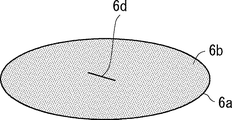
- FIG. 5 is a diagram showing image information obtained by imaging the upper surface of the powder.
- the speed of ascending inside the powder 6b differs depending on the specific gravity of the foreign matter 6d that is expected to be mixed in the object 6 to be inspected. Therefore, the period during which the foreign matter 6d, which is expected to be mixed in the object 6 to be inspected, reaches from the bottom surface of the container 6a to the top surface of the powder 6b is acquired in advance by simulation or experiment, and is the longest of the acquired periods. It is preferable to rotate the object to be inspected 6 while vibrating it for a period of more than one period. As a result, as shown in FIG. 5, the foreign matter 6d is exposed on the upper surface of the powder 6b.
- the period for rotating the object to be inspected 6 while vibrating may be set in advance, or may be set by the inspector via the display unit 9.
- the determination unit 5 determines whether or not the foreign matter 6d is detected based on the image information (S16). Specifically, the determination unit 5 calculates the difference in pixel values (that is, the difference between frames) of the corresponding pixels (that is, equal pixels) in the adjacent image information in time series, and the frame is equal to or larger than a preset threshold value. Determine if there is a difference between them. The difference between frames and the threshold value are absolute values.
- the determination unit 5 determines that the foreign matter 6d has been detected (YES in S16), and determines that the inspected body 6 is a defective product. Output to 8 (S17).
- the control unit 8 controls, for example, a robot arm (not shown) to carry the inspected body 6 to the defective product lane and perform an inspection operation. To finish.
- the determination unit 5 determines that the foreign matter 6d has not been detected (NO in S16), and determines that the inspected object 6 is a good product. Output to the control unit 8 (S18).
- the control unit 8 determines whether or not the inspected body 6 is vibrated at all the set vibration frequencies (S19). When the control unit 8 determines that the inspected body 6 is vibrated at all the set vibration frequencies (YES in S19), for example, the control unit 8 controls the robot arm (not shown) to carry the inspected body 6 to the non-defective lane. Then, the inspection work is completed.
- the control unit 8 determines that the inspected body 6 is not vibrating at all the set vibration frequencies (NO in S19)
- the control unit 8 executes the steps S14 to S19 at different vibration frequencies.
- the average value of the inter-frame difference of each pixel when the object 6 to be inspected was vibrated last time was calculated (S20), and the average value of the inter-frame difference of the pixels calculated last time was calculated this time. It may be subtracted from the frame-to-frame difference in the pixel.
- the inspection device 1 and the inspection method of the present embodiment can detect the inclusion of foreign matter 6d having a different volume by vibrating the inspected body 6 by changing the vibration frequency stepwise. Therefore, the inspection device 1 and the inspection method of the present embodiment can improve the inspection accuracy of the inspected body 6.
- the object to be inspected 6 is rotated to image a plurality of parts in the circumferential direction of the object to be inspected 6 (that is, the object to be inspected 6 is imaged from different directions), a foreign object is formed. Even if 6d is a long and thin object such as hair and one image information cannot capture the foreign matter 6d, the other image information can capture the foreign matter 6d. Therefore, the inspection accuracy of the inspected body 6 can be improved.
- the upper surface of the powder 6b is imaged at a frame rate equal to or higher than the maximum vibration frequency, there is a high possibility that the moment when the foreign matter 6d is exposed on the upper surface of the powder 6b can be imaged.
- the pixel group corresponding to the portion where the shadow appears on the upper surface of the powder 6b corresponds to the adjacent image information in time series as compared with the pixel group corresponding to the portion where the shadow does not appear on the upper surface of the powder 6b.
- the difference between pixel frames is small.
- the steps S11 to S15 are executed in advance using the object 6 to be inspected as a sample, and based on the acquired image information, the first pixel group corresponding to the portion where the shadow appears on the upper surface of the powder 6b and the shadow do not appear. It is discriminated from the second pixel group corresponding to the portion.
- the frame-to-frame difference of the corresponding pixel in the adjacent image information in time series is calculated, and the average value of the frame-to-frame difference in the first pixel group and the average value of the frame-to-frame difference in the second pixel group are calculated. To do.
- the first The calculated ratio may be integrated with the pixel values of the pixels of the pixel group to correct the pixel values.
- the threshold value used for detecting the foreign matter 6d in the first pixel group may be set to a value divided by the calculated ratio. That is, the threshold value used for detecting the foreign matter 6d in the first pixel group may be reduced by the calculated ratio to the threshold value used for detecting the foreign matter 6d in the second pixel group.
- the present invention has been described as a hardware configuration, but the present invention is not limited thereto.
- the present invention can also be realized by causing a CPU (Central Processing Unit) to execute a computer program to process each component.
- a CPU Central Processing Unit
- FIG. 6 is a diagram showing an example of the hardware configuration included in the processing device 7.
- the device 70 shown in FIG. 6 includes a processor 72 and a memory 73 together with the interface 71.
- the processing device 7 described in the above-described embodiment is realized by the processor 72 reading and executing the program stored in the memory 73. That is, this program is a program for causing the processor 72 to function as the processing device 7 of FIG.
- Non-temporary computer-readable media include various types of tangible storage media.
- Examples of non-transitory computer-readable media include magnetic recording media (eg, flexible disks, magnetic tapes, hard disk drives), magneto-optical recording media (eg, magneto-optical disks).
- this example includes a CD-ROM (Read Only Memory), a CD-R, and a CD-R / W.
- semiconductor memories eg, mask ROM, PROM, EPROM, flash ROM, RAM.
- the program may also be supplied to the computer by various types of temporary computer readable media. Examples of temporary computer-readable media include electrical, optical, and electromagnetic waves.
- the temporary computer-readable medium can supply the program to the computer via a wired communication path such as an electric wire and an optical fiber, or a wireless communication path.
- a plurality of parts having different circumferential directions of the inspected body 6 are imaged by rotating the inspected body 6, but the inspected body 6 is not rotated.
- a plurality of imaging units 4 By arranging a plurality of imaging units 4 around the body 6, a plurality of portions of the inspected body 6 having different circumferential directions may be imaged.
- the inspected body 6 is rotated around the rotation axis of the vibrating portion 2, the inspected body 6 may be arranged so that the inspected body 6 revolves around the rotation axis of the vibrating portion 2. Good. In short, it suffices if different parts can be imaged in the circumferential direction of the object 6 to be inspected.
- the vibration frequency is set according to the average particle size of the powder 6b and the volume of the foreign matter 6d that is expected to be mixed in the object 6 to be inspected.
- the particle size distribution of the powder 6b The vibration frequency may be set according to the volume of the foreign matter 6d that is expected to be mixed in the object 6 to be inspected. Further, the vibration frequency may be set according to the surface area or volume of the powder 6b and the volume of the foreign matter 6d that is expected to be mixed in the object 6 to be inspected. Further, the vibration frequency may be set according to the friction between the powder 6b and the object to be inspected 6.
- the vibrating unit 2 of the above-described embodiment has a configuration in which the inspected body 6 is placed, but it may also have a configuration in which the inspected body 6 is gripped to vibrate or rotate the inspected body 6. .. Further, the vibrating unit 2 may be, for example, a transfer table of the inspected body 6 arranged on the transfer line of the inspected body 6. In short, the vibrating unit 2 may have at least a configuration capable of vibrating the inspected body 6.
- Inspection device Vibration unit, 2a Stage 3 Light source 4 Imaging unit 5 Judgment unit 6 Inspected object, 6a container, 6b powder, 6c plug, 6d Foreign matter 7 Processing device 8 Control unit 9 Display unit 70 device, 71 interface, 72 Processor, 73 memory
Landscapes
- Engineering & Computer Science (AREA)
- Physics & Mathematics (AREA)
- General Physics & Mathematics (AREA)
- Computer Vision & Pattern Recognition (AREA)
- Theoretical Computer Science (AREA)
- General Health & Medical Sciences (AREA)
- Health & Medical Sciences (AREA)
- Multimedia (AREA)
- Chemical & Material Sciences (AREA)
- Life Sciences & Earth Sciences (AREA)
- Pathology (AREA)
- Immunology (AREA)
- Biochemistry (AREA)
- Analytical Chemistry (AREA)
- Mechanical Engineering (AREA)
- Computing Systems (AREA)
- Software Systems (AREA)
- Quality & Reliability (AREA)
- Medical Informatics (AREA)
- Artificial Intelligence (AREA)
- Evolutionary Computation (AREA)
- Databases & Information Systems (AREA)
- Signal Processing (AREA)
- Investigating Materials By The Use Of Optical Means Adapted For Particular Applications (AREA)
Abstract
Provided is an inspection device capable of contributing to the enhancement of detection accuracy for an object to be inspected. An inspection device (1) comprises: a vibration unit (2) for vibrating an object (6) to be inspected comprising a container (6a) containing a powder (6b) while changing the frequency of the vibration in steps; a light source (3) for emitting light onto the upper surface of the powder (6b); an imaging unit (4) for imaging the upper surface of the powder (6b) at a frame rate greater than or equal to the maximum vibration frequency of the vibration unit (2); and a determination unit (5) for determining whether the object (6) is an acceptable or defective product on the basis of image information imaged by the imaging unit (4).
Description
本開示は、検品装置、検品方法、及び非一時的なコンピュータ可読媒体に関する。
This disclosure relates to an inspection device, an inspection method, and a non-temporary computer-readable medium.
一般的な検品装置は、容器に被収容物が収容された被検査体に異物が混入しているか否かを判定することで、被検査体が良品か否かを判定する構成とされている。例えば、特許文献1の検品装置は、透明容器内に粉体が収容された被検査体に縦方向の振動と横方向の振動を加えて粉体を循環流動させながら、粉体が内面に接触している透明容器壁面を通じて、循環流動する粉体を撮像し、取得した画像情報に基づいて異物が混入しているか否かを判定する構成とされている。
A general inspection device is configured to determine whether or not an inspected object is a non-defective product by determining whether or not a foreign substance is mixed in the inspected object in which an inspected object is contained in a container. .. For example, in the inspection device of Patent Document 1, the powder comes into contact with the inner surface while circulating and flowing the powder by applying vertical vibration and horizontal vibration to the object to be inspected in which the powder is stored in a transparent container. The powder that circulates and flows is imaged through the wall surface of the transparent container, and it is determined whether or not foreign matter is mixed based on the acquired image information.
一般的な検品装置は、容積が異なる異物を良好に検出できない場合があり、被検査体の検品精度が低い課題を有していた。
A general inspection device may not be able to detect foreign substances having different volumes satisfactorily, and has a problem that the inspection accuracy of the inspected object is low.
本明細書に開示される実施形態が達成しようとする目的の1つは、当該課題の解決に寄与する検品装置、検品方法、及び非一時的なコンピュータ可読媒体を提供することである。なお、この目的は、本明細書に開示される複数の実施形態が達成しようとする複数の目的の1つに過ぎないことに留意されるべきである。その他の目的又は課題と新規な特徴は、本明細書の記述又は添付図面から明らかにされる。
One of the objectives to be achieved by the embodiments disclosed herein is to provide an inspection device, an inspection method, and a non-temporary computer-readable medium that contributes to the solution of the problem. It should be noted that this object is only one of the purposes that the embodiments disclosed herein seek to achieve. Other objectives or issues and novel features will be apparent from the description or accompanying drawings herein.
第1の態様の検品装置は、
振動周波数を段階的に変化させて、粉体が容器に収容された被検査体を振動させる振動部と、
前記粉体の上面に光を照射する光源と、
前記振動部の最高振動周波数以上のフレームレートで前記粉体の上面を撮像する撮像部と、
前記撮像部によって撮像された画像情報に基づいて、前記被検査体が良品か否かを判定する判定部と、
を備える。 The inspection device of the first aspect is
A vibrating part that vibrates the object to be inspected in which the powder is contained in the container by changing the vibration frequency stepwise.
A light source that irradiates the upper surface of the powder with light,
An imaging unit that images the upper surface of the powder at a frame rate equal to or higher than the maximum vibration frequency of the vibrating unit.
A determination unit that determines whether or not the object to be inspected is a non-defective product based on the image information captured by the imaging unit.
To be equipped.
第2の態様の検品方法は、
振動周波数を段階的に変化させて、粉体が容器に収容された被検査体を振動させ、
前記粉体の上面に光を照射し、
前記段階的に変化させる振動周波数の最高振動周波数以上のフレームレートで前記粉体の上面を撮像し、
撮像された画像情報に基づいて、前記被検査体が良品か否かを判定する。 The inspection method of the second aspect is
By changing the vibration frequency step by step, the powder vibrates the object to be inspected contained in the container.
Irradiate the upper surface of the powder with light to
The upper surface of the powder is imaged at a frame rate equal to or higher than the maximum vibration frequency of the vibration frequency to be changed stepwise.
Based on the captured image information, it is determined whether or not the inspected object is a non-defective product.
第3の態様の非一時的なコンピュータ可読媒体は、
振動周波数を段階的に変化させて、粉体が容器に収容された被検査体を振動させ、
前記粉体の上面に光を照射し、
前記段階的に変化させる振動周波数の最高振動周波数以上のフレームレートで前記粉体の上面を撮像し、
撮像された画像情報に基づいて、前記被検査体が良品か否かを判定することをコンピュータに実行させるプログラムが格納されている。 The non-transitory computer-readable medium of the third aspect is
By changing the vibration frequency step by step, the powder vibrates the object to be inspected contained in the container.
The upper surface of the powder is irradiated with light to
The upper surface of the powder is imaged at a frame rate equal to or higher than the maximum vibration frequency of the vibration frequency to be changed stepwise.
A program is stored that causes a computer to determine whether or not the object to be inspected is a non-defective product based on the captured image information.
上述の態様によれば、被検査体の検出精度の向上に寄与できる、検品装置、検品方法、及び非一時的なコンピュータ可読媒体を提供することができる。
According to the above aspect, it is possible to provide an inspection device, an inspection method, and a non-temporary computer-readable medium that can contribute to the improvement of the detection accuracy of the object to be inspected.
以下、本開示を実施するための最良の形態について、添付図面を参照しながら説明する。但し、本開示が以下の実施の形態に限定される訳ではない。また、説明を明確にするため、以下の記載及び図面は、適宜、簡略化されている。
Hereinafter, the best mode for carrying out the present disclosure will be described with reference to the attached drawings. However, the present disclosure is not limited to the following embodiments. Moreover, in order to clarify the description, the following description and drawings are simplified as appropriate.
<実施の形態1>
本実施の形態の検品装置及び検品方法は、粉体が容器内に封止された被検査体を振動させて粉体内で異物を浮上させ、異物を粉体の上面から露出させることで、被検査体に混入した異物を検出する。 <Embodiment 1>
The inspection device and inspection method of the present embodiment vibrate the object to be inspected in which the powder is sealed in a container to cause foreign matter to float in the powder and expose the foreign matter from the upper surface of the powder. Detects foreign matter mixed in the inspection body.
粉体としては、例えば、飲み薬又は注射薬などの粉末薬剤が好適である。但し、粉体は、粉末状であればよく、食料品などでもよい。容器は、光透過性を有するバイアル瓶、アンプル又は試験管などである。異物は、粉体と異なる物体であり、例えば、衣類などの繊維片、人体から抜け落ちる毛髪、被検査体などの生産ラインの部品片である金属片、容器などの破片である樹脂片やガラス片などである。
As the powder, for example, a powdered drug such as a swallowing drug or an injection drug is suitable. However, the powder may be in the form of powder, and may be a food product or the like. The container is a light-transmitting vial, ampoule, test tube, or the like. Foreign substances are objects different from powders, such as fiber fragments such as clothing, hair falling out of the human body, metal fragments that are parts of production lines such as objects to be inspected, resin fragments and glass fragments that are fragments such as containers. And so on.
先ず、本実施の形態の検品装置の最小限構成を説明する。図1は、本実施の形態の検品装置の最小限構成を示すブロック図である。検品装置1は、図1に示すように、振動部2、光源3、撮像部4及び判定部5を備えている。振動部2は、振動周波数を段階的に変化させて、粉体が容器内に収容された被検査体を振動させる。
First, the minimum configuration of the inspection device of this embodiment will be described. FIG. 1 is a block diagram showing a minimum configuration of the inspection device of the present embodiment. As shown in FIG. 1, the inspection device 1 includes a vibration unit 2, a light source 3, an image pickup unit 4, and a determination unit 5. The vibrating unit 2 changes the vibration frequency stepwise to vibrate the object to be inspected in which the powder is contained in the container.
このとき、異物が浮上する振動周波数は、例えば、粉体の平均粒子サイズと被検査体に混入することが想定される異物の容積との関係(例えば、比率など)によって異なるため、粉体の平均粒子サイズと被検査体に混入することが想定される異物の容積とに基づいて、予め複数の振動周波数が設定される。
At this time, the vibration frequency at which the foreign matter floats differs depending on the relationship (for example, the ratio) between the average particle size of the powder and the volume of the foreign matter that is expected to be mixed in the object to be inspected. A plurality of vibration frequencies are set in advance based on the average particle size and the volume of foreign matter that is expected to be mixed in the object to be inspected.
光源3は、粉体の上面に光を照射する。撮像部4は、振動部2の最高振動周波数以上のフレームレートで粉体の上面を撮像する。判定部5は、撮像部4によって撮像された画像情報に基づいて、被検査体が良品か否かを判定する。
The light source 3 irradiates the upper surface of the powder with light. The imaging unit 4 images the upper surface of the powder at a frame rate equal to or higher than the maximum vibration frequency of the vibrating unit 2. The determination unit 5 determines whether or not the inspected object is a non-defective product based on the image information captured by the imaging unit 4.
次に、本実施の形態の検品装置を用いた検査方法を説明する。図2は、本実施の形態の検査方法を示すフローチャート図である。先ず、振動部2による被検査体の振動を開始する(S1)。このとき、設定された複数の振動周波数のうち、一つの振動周波数を選択し、選択した振動周波数で被検査体を振動させる。
Next, an inspection method using the inspection device of the present embodiment will be described. FIG. 2 is a flowchart showing the inspection method of the present embodiment. First, the vibration unit 2 starts vibrating the object to be inspected (S1). At this time, one vibration frequency is selected from the set plurality of vibration frequencies, and the object to be inspected is vibrated at the selected vibration frequency.
そして、振動する被検査体の粉体の上面を撮像して画像情報を取得する(S2)。詳細には、光源3によって振動する被検査体の粉体の上面に光を照射しつつ、撮像部4によって粉体の上面を撮像する。
Then, the upper surface of the vibrating powder of the object to be inspected is imaged to acquire image information (S2). Specifically, the upper surface of the powder to be inspected vibrated by the light source 3 is irradiated with light, and the upper surface of the powder is imaged by the imaging unit 4.
次に、判定部5は、取得した画像情報に基づいて、被検査体が良品か否かを判定する(S3)。ここで、被検査体を振動させた際の振動周波数で浮上する容積の異物が粉体内に混入している場合、当該異物が粉体内を浮上して当該粉体の上面から露出する。
Next, the determination unit 5 determines whether or not the inspected object is a non-defective product based on the acquired image information (S3). Here, when a foreign substance having a volume that floats at the vibration frequency when the object to be inspected is vibrated is mixed in the powder, the foreign substance floats in the powder and is exposed from the upper surface of the powder.
そのため、判定部5は、取得した画像情報に基づいて、粉体の上面に異物を検出した場合、被検査体に異物が混入していると判定し、被検査体が不良品であると判定する(S3のNO)。一方、判定部5は、取得した画像情報に基づいて、粉体の上面に異物を検出しない場合、被検査体に異物が混入していないと判定し、被検査体が良品であると判定する(S3のYES)。
Therefore, when the determination unit 5 detects a foreign substance on the upper surface of the powder based on the acquired image information, it determines that the foreign substance is mixed in the inspected object, and determines that the inspected object is a defective product. (NO in S3). On the other hand, if the determination unit 5 does not detect a foreign substance on the upper surface of the powder based on the acquired image information, it determines that the object to be inspected is free of foreign substances and determines that the object to be inspected is a good product. (YES in S3).
その後、上述のS1~S3の工程を、振動周波数を段階的に変化させて予め設定された複数の振動周波数の全てで繰り返すと、被検査体の検品作業が終了する。このように本実施の形態の検品装置1及び検査方法は、振動周波数を段階的に変化させて被検査体を振動させることで、異なる容積の異物の混入を検出することができる。そのため、本実施の形態の検品装置1及び検品方法は、被検査体の検品精度を向上させることができる。
After that, when the above steps S1 to S3 are repeated at all of a plurality of preset vibration frequencies by changing the vibration frequency stepwise, the inspection work of the inspected object is completed. As described above, the inspection device 1 and the inspection method of the present embodiment can detect the mixing of foreign substances having different volumes by vibrating the object to be inspected by changing the vibration frequency stepwise. Therefore, the inspection device 1 and the inspection method of the present embodiment can improve the inspection accuracy of the inspected object.
次に、本実施の形態の検品装置1の具体的な構成を説明する。図3は、本実施の形態の検品装置の具体的な構成を示す図である。ここで、被検査体6は、例えば、図3に示すように、透明な容器6aの内部に粉体6bが収容された状態で栓6cによって封止された構成とされている。但し、被検査体6は、容器6aの内部に粉体6bが封止された構成であって、且つ容器6aが光透過性を有していればよい。
Next, a specific configuration of the inspection device 1 of the present embodiment will be described. FIG. 3 is a diagram showing a specific configuration of the inspection device of the present embodiment. Here, as shown in FIG. 3, for example, the object 6 to be inspected has a configuration in which the powder 6b is contained inside the transparent container 6a and is sealed by the stopper 6c. However, the object 6 to be inspected may have a structure in which the powder 6b is sealed inside the container 6a, and the container 6a may have light transmittance.
振動部2は、重力方向を下側とした場合、被検査体6を上下方向に振動させる。振動部2は、例えば、被検査体6を載置するステージ2aを備えており、当該ステージ2aを上下方向に振動させる構成とされている。このとき、詳細な機能は後述するが、ステージ2aは、上下方向に延在する回転軸を中心に回転する構成であればよい。
The vibrating unit 2 vibrates the inspected body 6 in the vertical direction when the direction of gravity is on the lower side. The vibrating unit 2 is provided with, for example, a stage 2a on which the inspected body 6 is placed, and is configured to vibrate the stage 2a in the vertical direction. At this time, although detailed functions will be described later, the stage 2a may be configured to rotate about a rotation axis extending in the vertical direction.
光源3は、容器6aを透過する波長域の光を粉体6bの上面の略全域に照射する。このとき、一つの光源3で一方向から粉体6bの上面の略全域を照射してもよく、複数の光源3で多方向から粉体6bの上面の略全域を照射してもよい。また、光源3としてリングライトなどを用いて粉体6bの上面の略全域を照射してもよい。
The light source 3 irradiates substantially the entire upper surface of the powder 6b with light in the wavelength range transmitted through the container 6a. At this time, one light source 3 may irradiate substantially the entire upper surface of the powder 6b from one direction, or a plurality of light sources 3 may irradiate substantially the entire upper surface of the powder 6b from multiple directions. Further, a ring light or the like may be used as the light source 3 to irradiate substantially the entire upper surface of the powder 6b.
撮像部4は、CMOS(Complementary Metal Oxide Semiconductor)やCCD(Charge Coupled Device)などの画像センサを備えており、粉体6bの上面の略全域を撮像する。そして、撮像部4は、取得した画像情報を判定部5に出力する。
The image pickup unit 4 is provided with an image sensor such as CMOS (Complementary Metal Oxide Semiconductor) or CCD (Charge Coupled Device), and images substantially the entire upper surface of the powder 6b. Then, the image pickup unit 4 outputs the acquired image information to the determination unit 5.
判定部5は、上述のように取得した画像情報に基づいて被検査体6が良品か否かを判定し、例えば、処理装置7に備えられている。処理装置7は、判定部5の他に制御部8を備えている。制御部8は、詳細は後述するが、振動部2、光源3及び撮像部4を制御する。
The determination unit 5 determines whether or not the inspected body 6 is a non-defective product based on the image information acquired as described above, and is provided in, for example, the processing device 7. The processing device 7 includes a control unit 8 in addition to the determination unit 5. Although the details will be described later, the control unit 8 controls the vibration unit 2, the light source 3, and the image pickup unit 4.
ここで、処理装置7に表示部9が電気的に接続されている場合、制御部8は、取得した画像情報が表示部9に表示されるように当該表示部9を制御すればよい。表示部9は、一般的な液晶表示パネルや有機EL(Electro Luminescence)パネルなどの表示装置を備えている。
Here, when the display unit 9 is electrically connected to the processing device 7, the control unit 8 may control the display unit 9 so that the acquired image information is displayed on the display unit 9. The display unit 9 includes a display device such as a general liquid crystal display panel or an organic EL (Electro Luminescence) panel.
このとき、表示部9は、表示装置上にタッチパネルを備えていると、検査員が表示部9を介して各種設定(例えば、複数の振動周波数の設定や被検査体6を振動させる際の振幅の設定など)を実現することができる。但し、検査員が各種設定を実現するための入力部を備えていてもよい。
At this time, if the display unit 9 is provided with a touch panel on the display device, the inspector sets various settings (for example, a plurality of vibration frequencies are set and the amplitude when the inspected body 6 is vibrated) via the display unit 9. Settings, etc.) can be realized. However, the inspector may be provided with an input unit for realizing various settings.
次に、本実施の形態の検品方法の具体的な流れを説明する。図4は、本実施の形態の検品方法の具体的な流れを示すフローチャート図である。先ず、検査員が表示部9を介して複数の振動周波数及び被検査体6を振動させる際の振幅を設定する(S11)。
Next, the specific flow of the inspection method of the present embodiment will be described. FIG. 4 is a flowchart showing a specific flow of the inspection method of the present embodiment. First, the inspector sets a plurality of vibration frequencies and an amplitude when the inspected body 6 is vibrated via the display unit 9 (S11).
詳細には、上述のように異物が浮上する振動周波数は、例えば、粉体6bの平均粒子サイズと被検査体6に混入することが想定される異物の容積との関係によって異なるため、粉体6bの平均粒子サイズと被検査体6に混入することが想定される異物の容積とに基づいて、複数の振動周波数を設定する。
Specifically, as described above, the vibration frequency at which the foreign matter floats differs depending on, for example, the relationship between the average particle size of the powder 6b and the volume of the foreign matter expected to be mixed in the object 6 to be inspected. A plurality of vibration frequencies are set based on the average particle size of 6b and the volume of foreign matter expected to be mixed in the object 6 to be inspected.
例えば、振動周波数は、10Hz以上500Hz以下の間で設定する。また、被検査体6を振動させる際の振幅は、粉体6bの平均粒子サイズの10倍以上に設定する。但し、被検査体6を振動させる際の振幅は、異物が浮上する振幅であればよい。
For example, the vibration frequency is set between 10 Hz and 500 Hz or less. Further, the amplitude when the object to be inspected 6 is vibrated is set to be 10 times or more the average particle size of the powder 6b. However, the amplitude when the object to be inspected 6 is vibrated may be any amplitude as long as the foreign matter floats.
ここで、平均粒子サイズは、画像解析法、遮光法、コールター法、沈殿法、レーザー解析、散乱法などによって予め算出することができる。つまり、平均粒子サイズは、一般的な粒子径を算出する手法を用いて算出することができる。
Here, the average particle size can be calculated in advance by an image analysis method, a shading method, a Coulter method, a precipitation method, a laser analysis, a scattering method, or the like. That is, the average particle size can be calculated by using a general method for calculating the particle size.
次に、複数の振動周波数及び被検査体6を振動させる際の振幅が設定されると、制御部8は、設定された振動周波数に基づいて、撮像部4のフレームレートを設定する(S12)。振動周波数に対して少ないフレームレートの場合、被検査体6を振動させることで粉体6bの上面から露出した異物が再び当該粉体6bの内部に潜った瞬間を撮像する可能性がある。そこで、制御部8は、設定された振動周波数の最高振動周波数以上のフレームレートに設定する。例えば、制御部8は、撮像部4のフレームレートを100fpsに設定する。
Next, when a plurality of vibration frequencies and amplitudes for vibrating the object 6 to be inspected are set, the control unit 8 sets the frame rate of the imaging unit 4 based on the set vibration frequencies (S12). .. When the frame rate is small with respect to the vibration frequency, there is a possibility that the moment when the foreign matter exposed from the upper surface of the powder 6b goes into the inside of the powder 6b again by vibrating the object 6 to be inspected is imaged. Therefore, the control unit 8 sets the frame rate to be equal to or higher than the maximum vibration frequency of the set vibration frequency. For example, the control unit 8 sets the frame rate of the imaging unit 4 to 100 fps.
次に、制御部8は、設定したフレームレートに基づいて、振動部2のステージ2aの回転速度を設定する(S13)。例えば、毛髪などの長細い異物の細さが撮像部4の1画素より小さい場合、異物の長手方向から当該異物を撮像しても、異物を良好に撮像できない場合がある。
Next, the control unit 8 sets the rotation speed of the stage 2a of the vibration unit 2 based on the set frame rate (S13). For example, when the fineness of a long and thin foreign matter such as hair is smaller than one pixel of the imaging unit 4, the foreign matter may not be captured well even if the foreign matter is imaged from the longitudinal direction of the foreign matter.
そこで、制御部8は、設定したフレームレートに基づいて、振動部2のステージ2aが一周する間に被検査体6を3画像以上撮像することができるように設定する。但し、振動部2のステージ2aの回転速度は、当該ステージ2aが回転することで被検査体6の対向する部分のみが撮像される回転速度でなければよい。
Therefore, the control unit 8 is set so that three or more images of the inspected body 6 can be captured while the stage 2a of the vibrating unit 2 goes around based on the set frame rate. However, the rotation speed of the stage 2a of the vibrating unit 2 may not be the rotation speed at which only the facing portion of the inspected body 6 is imaged by the rotation of the stage 2a.
次に、上下方向から見て、大凡、被検査体6の中心が振動部2の回転軸上に配置されるように、被検査体6がステージ2a上に配置された状態で、振動部2を制御してステージ2aを振動させつつ回転させる(S14)。
Next, when viewed from the vertical direction, the vibrating unit 2 is arranged in a state where the inspected body 6 is arranged on the stage 2a so that the center of the inspected body 6 is generally arranged on the rotation axis of the vibrating unit 2. Is controlled to rotate the stage 2a while vibrating (S14).
このとき、制御部8は、設定された複数の振動周波数のうち一つの振動周波数を選択し、選択した振動周波数であって、且つ設定した振幅でステージ2aを振動させつつ、設定したステージ2aの回転速度で当該ステージ2aを回転させる。これにより、被検査体6を振動させつつ振動部2の回転軸を中心に回転(即ち、自転)させることができる。
At this time, the control unit 8 selects one of the set vibration frequencies, and vibrates the stage 2a with the selected vibration frequency and the set amplitude, and the set stage 2a. The stage 2a is rotated at the rotation speed. As a result, the body 6 to be inspected can be vibrated and rotated (that is, rotated) about the rotation axis of the vibrating portion 2.
そして、制御部8は、光源3を制御して、振動しつつ回転する被検査体6の粉体6bの上面の略全域に光を照射させると共に、撮像部4を制御して、粉体6bの上面の略全域を撮像させる(S15)。これにより、撮像部4は、被検査体6の周方向において略等しい間隔で3画像以上の画像情報を取得し、取得した画像情報を判定部5に出力する。ここで、図5は、粉体の上面を撮像した画像情報を示す図である。
Then, the control unit 8 controls the light source 3 to irradiate substantially the entire upper surface of the powder 6b of the object 6 to be inspected rotating while vibrating, and controls the imaging unit 4 to control the powder 6b. The entire upper surface of the above surface is imaged (S15). As a result, the imaging unit 4 acquires image information of three or more images at substantially equal intervals in the circumferential direction of the object 6 to be inspected, and outputs the acquired image information to the determination unit 5. Here, FIG. 5 is a diagram showing image information obtained by imaging the upper surface of the powder.
ちなみに、被検査体6に混入することが想定される異物6dの比重によって粉体6bの内部で浮上する速度が異なる。そのため、予め被検査体6に混入することが想定される異物6dが容器6aの底面から粉体6bの上面まで到達する期間をシミュレーションや実験などで取得しておき、取得した期間のうち最も長かった期間以上の期間で被検査体6を振動させつつ回転させるとよい。その結果、図5に示すように、粉体6bの上面に異物6dが露出する。このような被検査体6を振動させつつ回転させる期間は、予め設定されていてもよいし、検査員が表示部9を介して設定してもよい。
By the way, the speed of ascending inside the powder 6b differs depending on the specific gravity of the foreign matter 6d that is expected to be mixed in the object 6 to be inspected. Therefore, the period during which the foreign matter 6d, which is expected to be mixed in the object 6 to be inspected, reaches from the bottom surface of the container 6a to the top surface of the powder 6b is acquired in advance by simulation or experiment, and is the longest of the acquired periods. It is preferable to rotate the object to be inspected 6 while vibrating it for a period of more than one period. As a result, as shown in FIG. 5, the foreign matter 6d is exposed on the upper surface of the powder 6b. The period for rotating the object to be inspected 6 while vibrating may be set in advance, or may be set by the inspector via the display unit 9.
次に、判定部5は、画像情報に基づいて、異物6dを検出したか否かを判定する(S16)。詳細には、判定部5は、時系列で隣接する画像情報において対応する画素(即ち、等しい画素)の画素値の差分(即ち、フレーム間差分)を算出し、予め設定された閾値以上のフレーム間差分が存在するか否かを判定する。なお、フレーム間差分及び閾値は、絶対値の値である。
Next, the determination unit 5 determines whether or not the foreign matter 6d is detected based on the image information (S16). Specifically, the determination unit 5 calculates the difference in pixel values (that is, the difference between frames) of the corresponding pixels (that is, equal pixels) in the adjacent image information in time series, and the frame is equal to or larger than a preset threshold value. Determine if there is a difference between them. The difference between frames and the threshold value are absolute values.
予め設定された閾値以上のフレーム間差分が存在する場合、判定部5は、異物6dが検出されたと判定し(S16のYES)、被検査体6が不良品であるとの判定結果を制御部8に出力する(S17)。制御部8は、被検査体6が不良品であるとの判定結果が入力されると、例えば、図示を省略したロボットアームを制御して被検査体6を不良品レーンに搬出し、検品作業を終了する。
When there is a frame-to-frame difference equal to or greater than a preset threshold value, the determination unit 5 determines that the foreign matter 6d has been detected (YES in S16), and determines that the inspected body 6 is a defective product. Output to 8 (S17). When the determination result that the inspected body 6 is a defective product is input, the control unit 8 controls, for example, a robot arm (not shown) to carry the inspected body 6 to the defective product lane and perform an inspection operation. To finish.
一方、予め設定された閾値以上のフレーム間差分が存在しない場合、判定部5は、異物6dを検出しなかったと判定し(S16のNO)、被検査体6が良品であるとの判定結果を制御部8に出力する(S18)。
On the other hand, when there is no inter-frame difference equal to or greater than a preset threshold value, the determination unit 5 determines that the foreign matter 6d has not been detected (NO in S16), and determines that the inspected object 6 is a good product. Output to the control unit 8 (S18).
次に、制御部8は、被検査体6が良品であるとの判定結果が入力された場合、設定した全ての振動周波数で被検査体6を振動させたか否かを判定する(S19)。制御部8は、設定した全ての振動周波数で被検査体6を振動させたと判定した場合(S19のYES)、例えば、図示を省略したロボットアームを制御して被検査体6を良品レーンに搬出し、検品作業を終了する。
Next, when the determination result that the inspected body 6 is a good product is input, the control unit 8 determines whether or not the inspected body 6 is vibrated at all the set vibration frequencies (S19). When the control unit 8 determines that the inspected body 6 is vibrated at all the set vibration frequencies (YES in S19), for example, the control unit 8 controls the robot arm (not shown) to carry the inspected body 6 to the non-defective lane. Then, the inspection work is completed.
一方、制御部8は、設定した全ての振動周波数で被検査体6を振動させていないと判定した場合(S19のNO)、異なる振動周波数でS14~S19の工程を実行する。このとき、前回、被検査体6を振動させた際の各々の画素でのフレーム間差分の平均値を算出し(S20)、前回、算出した画素のフレーム間差分の平均値を、今回、算出した当該画素でのフレーム間差分から減算してもよい。これにより、被検査体6が一周している間に、振動によって粉体6bの上面の形状が変化してフレーム間差分に影響を及ぼしても、異物6dと誤判定することを抑制できる。
On the other hand, when the control unit 8 determines that the inspected body 6 is not vibrating at all the set vibration frequencies (NO in S19), the control unit 8 executes the steps S14 to S19 at different vibration frequencies. At this time, the average value of the inter-frame difference of each pixel when the object 6 to be inspected was vibrated last time was calculated (S20), and the average value of the inter-frame difference of the pixels calculated last time was calculated this time. It may be subtracted from the frame-to-frame difference in the pixel. As a result, even if the shape of the upper surface of the powder 6b changes due to vibration while the object 6 to be inspected goes around and affects the difference between frames, it is possible to prevent erroneous determination as foreign matter 6d.
このように本実施の形態の検品装置1及び検品方法は、振動周波数を段階的に変化させて被検査体6を振動させることで、異なる容積の異物6dの混入を検出することができる。そのため、本実施の形態の検品装置1及び検品方法は、被検査体6の検品精度を向上させることができる。
As described above, the inspection device 1 and the inspection method of the present embodiment can detect the inclusion of foreign matter 6d having a different volume by vibrating the inspected body 6 by changing the vibration frequency stepwise. Therefore, the inspection device 1 and the inspection method of the present embodiment can improve the inspection accuracy of the inspected body 6.
しかも、被検査体6を回転させて当該被検査体6が一周する間に、被検査体6の周方向において複数の部分を(即ち、被検査体6を異なる方向から)撮像するので、異物6dが毛髪などの長細い物体であって、一の画像情報では、異物6dを撮像できなくても、他の画像情報では、異物6dを撮像することができる。そのため、被検査体6の検品精度を向上させることができる。
Moreover, since the object to be inspected 6 is rotated to image a plurality of parts in the circumferential direction of the object to be inspected 6 (that is, the object to be inspected 6 is imaged from different directions), a foreign object is formed. Even if 6d is a long and thin object such as hair and one image information cannot capture the foreign matter 6d, the other image information can capture the foreign matter 6d. Therefore, the inspection accuracy of the inspected body 6 can be improved.
また、最高振動周波数以上のフレームレートで粉体6bの上面を撮像するので、異物6dが粉体6bの上面に露出している瞬間を撮像できる可能性が高い。
Further, since the upper surface of the powder 6b is imaged at a frame rate equal to or higher than the maximum vibration frequency, there is a high possibility that the moment when the foreign matter 6d is exposed on the upper surface of the powder 6b can be imaged.
<実施の形態2>
光源3によって粉体6bの上面に光を照射する場合、粉体6bの上面に容器6aの陰が現れる可能性がある。そして、実施の形態1の検品装置1の構成の場合、容器6aの陰は粉体6bの上面の定まった位置に現れる。 <Embodiment 2>
When thelight source 3 irradiates the upper surface of the powder 6b with light, the shadow of the container 6a may appear on the upper surface of the powder 6b. Then, in the case of the configuration of the inspection device 1 of the first embodiment, the shadow of the container 6a appears at a fixed position on the upper surface of the powder 6b.
光源3によって粉体6bの上面に光を照射する場合、粉体6bの上面に容器6aの陰が現れる可能性がある。そして、実施の形態1の検品装置1の構成の場合、容器6aの陰は粉体6bの上面の定まった位置に現れる。 <
When the
このとき、粉体6bの上面で陰が現れる部分に該当する画素群では、粉体6bの上面で陰が現れない部分に該当する画素群に比べて、時系列で隣接する画像情報において対応する画素のフレーム間差分が小さい。
At this time, the pixel group corresponding to the portion where the shadow appears on the upper surface of the powder 6b corresponds to the adjacent image information in time series as compared with the pixel group corresponding to the portion where the shadow does not appear on the upper surface of the powder 6b. The difference between pixel frames is small.
そこで、予め被検査体6をサンプルとしてS11~S15の工程を実行し、取得した画像情報に基づいて、粉体6bの上面で陰が現れる部分に該当する第1の画素群と陰が現れない部分に該当する第2の画素群とに判別する。
Therefore, the steps S11 to S15 are executed in advance using the object 6 to be inspected as a sample, and based on the acquired image information, the first pixel group corresponding to the portion where the shadow appears on the upper surface of the powder 6b and the shadow do not appear. It is discriminated from the second pixel group corresponding to the portion.
そして、時系列で隣接する画像情報において対応する画素のフレーム間差分を算出し、第1の画素群でのフレーム間差分の平均値及び第2の画素群でのフレーム間差分の平均値を算出する。
Then, the frame-to-frame difference of the corresponding pixel in the adjacent image information in time series is calculated, and the average value of the frame-to-frame difference in the first pixel group and the average value of the frame-to-frame difference in the second pixel group are calculated. To do.
さらに、例えば、第1の画素群でのフレーム間差分の平均値に対する第2の画素群でのフレーム間差分の平均値の比率を算出し、被検査体6を検品する際に、第1の画素群の画素の画素値に算出した比率を積算して当該画素値を補正してもよい。
Further, for example, when the ratio of the average value of the inter-frame difference in the second pixel group to the average value of the inter-frame difference in the first pixel group is calculated and the inspected object 6 is inspected, the first The calculated ratio may be integrated with the pixel values of the pixels of the pixel group to correct the pixel values.
これにより、粉体6bの上面に現れた陰をキャンセルすることができ、異物6dの検出漏れを抑制できる。但し、第1の画素群で異物6dを検出するために用いる閾値として、第2の画素群で異物6dを検出するために用いる閾値を、算出した比率で除算した値に設定してもよい。つまり、第2の画素群で異物6dを検出するために用いる閾値に対して、第1の画素群で異物6dを検出するために用いる閾値を算出した比率で小さくしてもよい。
As a result, the shadow appearing on the upper surface of the powder 6b can be canceled, and the omission of detection of the foreign matter 6d can be suppressed. However, as the threshold value used for detecting the foreign matter 6d in the first pixel group, the threshold value used for detecting the foreign matter 6d in the second pixel group may be set to a value divided by the calculated ratio. That is, the threshold value used for detecting the foreign matter 6d in the first pixel group may be reduced by the calculated ratio to the threshold value used for detecting the foreign matter 6d in the second pixel group.
<他の実施の形態>
なお、上述した実施の形態1及び2では、本発明をハードウェアの構成として説明したが、本発明はこれに限定されるものではない。本発明は、各構成要素の処理を、CPU(Central Processing Unit)にコンピュータプログラムを実行させることにより実現することも可能である。 <Other embodiments>
In the above-described first and second embodiments, the present invention has been described as a hardware configuration, but the present invention is not limited thereto. The present invention can also be realized by causing a CPU (Central Processing Unit) to execute a computer program to process each component.
例えば、上述した実施の形態に係る処理装置7は、次のようなハードウェア構成を備えることができる。図6は、処理装置7に含まれるハードウェア構成の一例を示す図である。
For example, the processing device 7 according to the above-described embodiment can be provided with the following hardware configuration. FIG. 6 is a diagram showing an example of the hardware configuration included in the processing device 7.
図6に示す装置70は、インターフェイス71とともに、プロセッサ72及びメモリ73を備えている。上述した実施の形態で説明した処理装置7は、プロセッサ72がメモリ73に記憶されたプログラムを読み込んで実行することにより実現される。つまり、このプログラムは、プロセッサ72を図3の処理装置7として機能させるためのプログラムである。
The device 70 shown in FIG. 6 includes a processor 72 and a memory 73 together with the interface 71. The processing device 7 described in the above-described embodiment is realized by the processor 72 reading and executing the program stored in the memory 73. That is, this program is a program for causing the processor 72 to function as the processing device 7 of FIG.
上述したプログラムは、様々なタイプの非一時的なコンピュータ可読媒体(non-transitory computer readable medium)を用いて格納され、コンピュータ(情報通知装置を含むコンピュータ)に供給することができる。非一時的なコンピュータ可読媒体は、様々なタイプの実体のある記録媒体(tangible storage medium)を含む。非一時的なコンピュータ可読媒体の例は、磁気記録媒体(例えばフレキシブルディスク、磁気テープ、ハードディスクドライブ)、光磁気記録媒体(例えば光磁気ディスク)を含む。さらに、この例は、CD-ROM(Read Only Memory)、CD-R、CD-R/Wを含む。さらに、この例は、半導体メモリ(例えば、マスクROM、PROM、EPROM、フラッシュROM、RAM)を含む。また、プログラムは、様々なタイプの一時的なコンピュータ可読媒体(transitory computer readable medium)によってコンピュータに供給されてもよい。一時的なコンピュータ可読媒体の例は、電気信号、光信号、及び電磁波を含む。一時的なコンピュータ可読媒体は、電線及び光ファイバ等の有線通信路、又は無線通信路を介して、プログラムをコンピュータに供給できる。
The above-mentioned program is stored using various types of non-transitory computer readable medium and can be supplied to a computer (a computer including an information notification device). Non-temporary computer-readable media include various types of tangible storage media. Examples of non-transitory computer-readable media include magnetic recording media (eg, flexible disks, magnetic tapes, hard disk drives), magneto-optical recording media (eg, magneto-optical disks). Further, this example includes a CD-ROM (Read Only Memory), a CD-R, and a CD-R / W. Further, this example includes semiconductor memories (eg, mask ROM, PROM, EPROM, flash ROM, RAM). The program may also be supplied to the computer by various types of temporary computer readable media. Examples of temporary computer-readable media include electrical, optical, and electromagnetic waves. The temporary computer-readable medium can supply the program to the computer via a wired communication path such as an electric wire and an optical fiber, or a wireless communication path.
なお、本開示は上述した実施の形態に限られたものではなく、趣旨を逸脱しない範囲で適宜変更することが可能である。また、本開示は、それぞれの実施の形態を適宜組み合わせて実施されてもよい。
Note that this disclosure is not limited to the above-described embodiment, and can be appropriately modified without departing from the spirit. Further, the present disclosure may be carried out by appropriately combining the respective embodiments.
上述した実施の形態では、被検査体6を回転させることで、被検査体6の周方向の異なる複数の部分を撮像しているが、被検査体6を回転させることなく、被検査体6の周囲に複数の撮像部4を配置することで、被検査体6の周方向の異なる複数の部分を撮像してもよい。また、振動部2の回転軸を中心に被検査体6を自転させているが、振動部2の回転軸を中心に被検査体6が公転するように当該被検査体6を配置してもよい。要するに、被検査体6の周方向において異なる部分を撮像できればよい。
In the above-described embodiment, a plurality of parts having different circumferential directions of the inspected body 6 are imaged by rotating the inspected body 6, but the inspected body 6 is not rotated. By arranging a plurality of imaging units 4 around the body 6, a plurality of portions of the inspected body 6 having different circumferential directions may be imaged. Further, although the inspected body 6 is rotated around the rotation axis of the vibrating portion 2, the inspected body 6 may be arranged so that the inspected body 6 revolves around the rotation axis of the vibrating portion 2. Good. In short, it suffices if different parts can be imaged in the circumferential direction of the object 6 to be inspected.
上述した実施の形態では、粉体6bの平均粒子サイズと被検査体6に混入することが想定される異物6dの容積とに応じて振動周波数を設定しているが、粉体6bの粒度分布と被検査体6に混入することが想定される異物6dの容積とに応じて振動周波数を設定してもよい。また、粉体6bの表面積又は容積と被検査体6に混入することが想定される異物6dの容積とに応じて振動周波数を設定してもよい。さらに、粉体6bと被検査体6との摩擦に応じて振動周波数を設定してもよい。
In the above-described embodiment, the vibration frequency is set according to the average particle size of the powder 6b and the volume of the foreign matter 6d that is expected to be mixed in the object 6 to be inspected. However, the particle size distribution of the powder 6b The vibration frequency may be set according to the volume of the foreign matter 6d that is expected to be mixed in the object 6 to be inspected. Further, the vibration frequency may be set according to the surface area or volume of the powder 6b and the volume of the foreign matter 6d that is expected to be mixed in the object 6 to be inspected. Further, the vibration frequency may be set according to the friction between the powder 6b and the object to be inspected 6.
上述した実施の形態の振動部2は、被検査体6が載置される構成であるが、被検査体6を把持して被検査体6を振動させたり、回転させたり、する構成でもよい。また、振動部2は、例えば、被検査体6の搬送ラインに配置された当該被検査体6の搬送台であってもよい。要するに、振動部2は、少なくとも被検査体6を振動させることができる構成であればよい。
The vibrating unit 2 of the above-described embodiment has a configuration in which the inspected body 6 is placed, but it may also have a configuration in which the inspected body 6 is gripped to vibrate or rotate the inspected body 6. .. Further, the vibrating unit 2 may be, for example, a transfer table of the inspected body 6 arranged on the transfer line of the inspected body 6. In short, the vibrating unit 2 may have at least a configuration capable of vibrating the inspected body 6.
1 検品装置
2 振動部、2a ステージ
3 光源
4 撮像部
5 判定部
6 被検査体、6a 容器、6b 粉体、6c 栓、6d 異物
7 処理装置
8 制御部
9 表示部
70 装置、71 インターフェイス、72 プロセッサ、73 メモリ 1Inspection device 2 Vibration unit, 2a Stage 3 Light source 4 Imaging unit 5 Judgment unit 6 Inspected object, 6a container, 6b powder, 6c plug, 6d Foreign matter 7 Processing device 8 Control unit 9 Display unit 70 device, 71 interface, 72 Processor, 73 memory
2 振動部、2a ステージ
3 光源
4 撮像部
5 判定部
6 被検査体、6a 容器、6b 粉体、6c 栓、6d 異物
7 処理装置
8 制御部
9 表示部
70 装置、71 インターフェイス、72 プロセッサ、73 メモリ 1
Claims (15)
- 振動周波数を段階的に変化させて、粉体が容器に収容された被検査体を振動させる振動部と、
前記粉体の上面に光を照射する光源と、
前記振動部の最高振動周波数以上のフレームレートで前記粉体の上面を撮像する撮像部と、
前記撮像部によって撮像された画像情報に基づいて、前記被検査体が良品か否かを判定する判定部と、
を備える、検品装置。 A vibrating part that vibrates the object to be inspected in which the powder is contained in the container by changing the vibration frequency stepwise.
A light source that irradiates the upper surface of the powder with light,
An imaging unit that images the upper surface of the powder at a frame rate equal to or higher than the maximum vibration frequency of the vibrating unit.
A determination unit that determines whether or not the object to be inspected is a non-defective product based on the image information captured by the imaging unit.
Inspector equipped with. - 重力方向を下側とした場合、前記振動部は、前記被検査体を上下方向に振動させる、請求項1に記載の検品装置。 The inspection device according to claim 1, wherein the vibrating portion vibrates the object to be inspected in the vertical direction when the direction of gravity is on the lower side.
- 重力方向を下側とした場合、前記振動部は、上下方向に延在する回転軸を中心に、各々の振動周波数で前記被検査体が少なくとも1周するように当該被検査体を回転させる、請求項1又は2に記載の検品装置。 When the direction of gravity is on the lower side, the vibrating portion rotates the inspected object around a rotation axis extending in the vertical direction so that the inspected object makes at least one revolution at each vibration frequency. The inspection device according to claim 1 or 2.
- 前記撮像部は、前記被検査体が1周する間に複数画像撮像する、請求項3に記載の検品装置。 The inspection device according to claim 3, wherein the imaging unit captures a plurality of images while the object to be inspected makes one round.
- 前記撮像部は、前記被検査体の周方向に等しい間隔で3画像以上撮像する、請求項4に記載の検品装置。 The inspection device according to claim 4, wherein the imaging unit captures three or more images at equal intervals in the circumferential direction of the object to be inspected.
- 前記振動周波数は、前記粉体の平均粒子サイズと予め設定された前記被検査体に混入することが想定される異物の容積とに応じて設定される、請求項1乃至5のいずれか1項に記載の検品装置。 The vibration frequency is set according to the average particle size of the powder and the preset volume of foreign matter that is expected to be mixed in the object to be inspected, according to any one of claims 1 to 5. The inspection device described in.
- 前記判定部は、時系列で隣接する画像情報において対応する画素の画素値の差分を算出し、算出した差分が予め設定された閾値以上の場合、前記被検査体が不良品であると判定する、請求項1乃至6のいずれか1項に記載の検品装置。 The determination unit calculates the difference between the pixel values of the corresponding pixels in the adjacent image information in time series, and if the calculated difference is equal to or greater than a preset threshold value, determines that the inspected object is a defective product. , The inspection device according to any one of claims 1 to 6.
- 振動周波数を段階的に変化させて、粉体が容器に収容された被検査体を振動させ、
前記粉体の上面に光を照射し、
前記段階的に変化させる振動周波数の最高振動周波数以上のフレームレートで前記粉体の上面を撮像し、
撮像された画像情報に基づいて、前記被検査体が良品か否かを判定する、検品方法。 By changing the vibration frequency step by step, the powder vibrates the object to be inspected contained in the container.
Irradiate the upper surface of the powder with light to
The upper surface of the powder is imaged at a frame rate equal to or higher than the maximum vibration frequency of the vibration frequency to be changed stepwise.
An inspection method for determining whether or not the object to be inspected is a non-defective product based on the captured image information. - 重力方向を下側とした場合、前記被検査体を上下方向に振動させる、請求項8に記載の検品方法。 The inspection method according to claim 8, wherein the object to be inspected is vibrated in the vertical direction when the direction of gravity is on the lower side.
- 重力方向を下側とした場合、上下方向に延在する回転軸を中心に、各々の振動周波数で前記被検査体が少なくとも1周するように当該被検査体を回転させる、請求項8又は9に記載の検品方法。 Claim 8 or 9, when the direction of gravity is on the lower side, the object to be inspected is rotated around a rotation axis extending in the vertical direction so that the object to be inspected makes at least one revolution at each vibration frequency. Inspection method described in.
- 前記被検査体が1周する間に複数画像撮像する、請求項10に記載の検品方法。 The inspection method according to claim 10, wherein a plurality of images are imaged while the object to be inspected makes one round.
- 前記被検査体の周方向に等しい間隔で3画像以上撮像する、請求項11に記載の検品方法。 The inspection method according to claim 11, wherein three or more images are taken at equal intervals in the circumferential direction of the object to be inspected.
- 前記振動周波数は、前記粉体の平均粒子サイズと予め設定された前記被検査体に混入することが想定される異物の容積とに応じて設定される、請求項8乃至12のいずれか1項に記載の検品方法。 The vibration frequency is set according to the average particle size of the powder and the preset volume of foreign matter that is expected to be mixed in the object to be inspected, according to any one of claims 8 to 12. Inspection method described in.
- 時系列で隣接する画像情報において対応する画素の画素値の差分を算出し、算出した差分が予め設定された閾値以上の場合、前記被検査体が不良品であると判定する、請求項8乃至13のいずれか1項に記載の検品方法。 Claims 8 to 8 to claim, wherein the difference between the pixel values of the corresponding pixels in the adjacent image information in time series is calculated, and when the calculated difference is equal to or more than a preset threshold value, it is determined that the inspected object is a defective product. The inspection method according to any one of 13.
- 振動周波数を段階的に変化させて、粉体が容器に収容された被検査体を振動させ、
前記粉体の上面に光を照射し、
前記段階的に変化させる振動周波数の最高振動周波数以上のフレームレートで前記粉体の上面を撮像し、
撮像された画像情報に基づいて、前記被検査体が良品か否かを判定することをコンピュータに実行させるプログラムが格納された非一時的なコンピュータ可読媒体。 By changing the vibration frequency step by step, the powder vibrates the object to be inspected contained in the container.
Irradiate the upper surface of the powder with light to
The upper surface of the powder is imaged at a frame rate equal to or higher than the maximum vibration frequency of the vibration frequency to be changed stepwise.
A non-temporary computer-readable medium containing a program that causes a computer to determine whether or not the inspected object is a non-defective product based on the captured image information.
Priority Applications (4)
| Application Number | Priority Date | Filing Date | Title |
|---|---|---|---|
| US17/437,631 US11972555B2 (en) | 2019-03-19 | 2019-03-19 | Product-inspection apparatus, product-inspection method, and non-transitory computer readable medium |
| JP2021506875A JP7238964B2 (en) | 2019-03-19 | 2019-03-19 | Inspection device, inspection method, and program |
| PCT/JP2019/011346 WO2020188728A1 (en) | 2019-03-19 | 2019-03-19 | Inspection device, inspection method, and non-transitory computer-readable medium |
| EP19920093.2A EP3943921A4 (en) | 2019-03-19 | 2019-03-19 | Inspection device, inspection method, and non-transitory computer-readable medium |
Applications Claiming Priority (1)
| Application Number | Priority Date | Filing Date | Title |
|---|---|---|---|
| PCT/JP2019/011346 WO2020188728A1 (en) | 2019-03-19 | 2019-03-19 | Inspection device, inspection method, and non-transitory computer-readable medium |
Publications (1)
| Publication Number | Publication Date |
|---|---|
| WO2020188728A1 true WO2020188728A1 (en) | 2020-09-24 |
Family
ID=72519278
Family Applications (1)
| Application Number | Title | Priority Date | Filing Date |
|---|---|---|---|
| PCT/JP2019/011346 WO2020188728A1 (en) | 2019-03-19 | 2019-03-19 | Inspection device, inspection method, and non-transitory computer-readable medium |
Country Status (4)
| Country | Link |
|---|---|
| US (1) | US11972555B2 (en) |
| EP (1) | EP3943921A4 (en) |
| JP (1) | JP7238964B2 (en) |
| WO (1) | WO2020188728A1 (en) |
Citations (11)
| Publication number | Priority date | Publication date | Assignee | Title |
|---|---|---|---|---|
| JPS537459B2 (en) | 1976-04-12 | 1978-03-17 | ||
| JPH01272948A (en) * | 1988-04-26 | 1989-10-31 | Mitsubishi Heavy Ind Ltd | Inspecting method for foreign matter in real bottle |
| JP2000298103A (en) * | 1999-04-15 | 2000-10-24 | Nittetsu Mining Co Ltd | Foreign matter inspecting device for powder in transparent container |
| JP2001004549A (en) * | 1999-06-24 | 2001-01-12 | Dai Ichi Seiyaku Co Ltd | Device for detecting foreign matter in powder |
| JP2004257937A (en) * | 2003-02-27 | 2004-09-16 | Japan System Kk | Foreign matter inspection device and inspection method |
| JP2005030810A (en) * | 2003-07-08 | 2005-02-03 | Asahi Shuzo Kk | Foreign matter inspection device |
| JP2010008339A (en) * | 2008-06-30 | 2010-01-14 | Decsys:Kk | Method and device for inspecting foreign matter in powder in transparent vessel |
| JP2011080936A (en) * | 2009-10-09 | 2011-04-21 | Eisai Machinery Co Ltd | Foreign matter inspection apparatus and method |
| JP2014006186A (en) * | 2012-06-26 | 2014-01-16 | Fuji Electric Co Ltd | Foreign matter inspection device |
| JP2014145652A (en) * | 2013-01-29 | 2014-08-14 | Fuji Electric Co Ltd | Foreign matter inspection apparatus |
| WO2018002049A1 (en) * | 2016-06-28 | 2018-01-04 | F. Hoffmann-La Roche Ag | Inspection device |
Family Cites Families (5)
| Publication number | Priority date | Publication date | Assignee | Title |
|---|---|---|---|---|
| JP2719410B2 (en) | 1989-07-19 | 1998-02-25 | 日鉄鉱業株式会社 | Automatic inspection equipment for powder sealed transparent containers |
| JP5994416B2 (en) * | 2012-06-18 | 2016-09-21 | ニプロ株式会社 | Foreign matter detection device and foreign matter detection method in powder using terahertz pulse wave |
| JPWO2014064897A1 (en) * | 2012-10-25 | 2016-09-08 | 日本電気株式会社 | Information processing apparatus, information processing method, and information processing program |
| CN106312062B (en) * | 2016-08-02 | 2018-09-25 | 西安铂力特增材技术股份有限公司 | A kind of method and increasing material manufacturing equipment for examining powdering quality |
| US11344949B2 (en) * | 2018-06-08 | 2022-05-31 | General Electric Company | Powder removal floating structures |
-
2019
- 2019-03-19 US US17/437,631 patent/US11972555B2/en active Active
- 2019-03-19 WO PCT/JP2019/011346 patent/WO2020188728A1/en unknown
- 2019-03-19 JP JP2021506875A patent/JP7238964B2/en active Active
- 2019-03-19 EP EP19920093.2A patent/EP3943921A4/en active Pending
Patent Citations (11)
| Publication number | Priority date | Publication date | Assignee | Title |
|---|---|---|---|---|
| JPS537459B2 (en) | 1976-04-12 | 1978-03-17 | ||
| JPH01272948A (en) * | 1988-04-26 | 1989-10-31 | Mitsubishi Heavy Ind Ltd | Inspecting method for foreign matter in real bottle |
| JP2000298103A (en) * | 1999-04-15 | 2000-10-24 | Nittetsu Mining Co Ltd | Foreign matter inspecting device for powder in transparent container |
| JP2001004549A (en) * | 1999-06-24 | 2001-01-12 | Dai Ichi Seiyaku Co Ltd | Device for detecting foreign matter in powder |
| JP2004257937A (en) * | 2003-02-27 | 2004-09-16 | Japan System Kk | Foreign matter inspection device and inspection method |
| JP2005030810A (en) * | 2003-07-08 | 2005-02-03 | Asahi Shuzo Kk | Foreign matter inspection device |
| JP2010008339A (en) * | 2008-06-30 | 2010-01-14 | Decsys:Kk | Method and device for inspecting foreign matter in powder in transparent vessel |
| JP2011080936A (en) * | 2009-10-09 | 2011-04-21 | Eisai Machinery Co Ltd | Foreign matter inspection apparatus and method |
| JP2014006186A (en) * | 2012-06-26 | 2014-01-16 | Fuji Electric Co Ltd | Foreign matter inspection device |
| JP2014145652A (en) * | 2013-01-29 | 2014-08-14 | Fuji Electric Co Ltd | Foreign matter inspection apparatus |
| WO2018002049A1 (en) * | 2016-06-28 | 2018-01-04 | F. Hoffmann-La Roche Ag | Inspection device |
Non-Patent Citations (1)
| Title |
|---|
| See also references of EP3943921A4 |
Also Published As
| Publication number | Publication date |
|---|---|
| EP3943921A1 (en) | 2022-01-26 |
| JP7238964B2 (en) | 2023-03-14 |
| JPWO2020188728A1 (en) | 2020-09-24 |
| US11972555B2 (en) | 2024-04-30 |
| EP3943921A4 (en) | 2022-03-16 |
| US20220148144A1 (en) | 2022-05-12 |
Similar Documents
| Publication | Publication Date | Title |
|---|---|---|
| JP7216146B2 (en) | Method and apparatus for nondestructive detection of undissolved particles in fluids | |
| JP5918508B2 (en) | Apparatus and method for detecting solids in liquid phase | |
| CN109932369A (en) | A kind of abnormity display panel testing method and device | |
| WO2017104662A1 (en) | Particle analysis device and particle analysis method | |
| JP2010008339A (en) | Method and device for inspecting foreign matter in powder in transparent vessel | |
| WO2020188728A1 (en) | Inspection device, inspection method, and non-transitory computer-readable medium | |
| US11977208B2 (en) | Removal of liquid drops from optical element | |
| US11325157B2 (en) | Device and method for capturing movement patterns of tumbler screening machines | |
| JP4906602B2 (en) | Defect inspection apparatus and defect inspection method for polycrystalline silicon substrate | |
| WO2020188730A1 (en) | Inspection device, inspection method, and non-transitory computer-readable medium | |
| US20220189000A1 (en) | Product-inspection apparatus, product-inspection method, and non-transitory computer readable medium | |
| JP2018205199A (en) | Foreign matter inspection device and method | |
| JP4163039B2 (en) | In-container bubble determination method and apparatus | |
| JPH11337470A (en) | Flow-type particle image analyzer | |
| JP2006194788A (en) | Particle image processing method and device, and its program | |
| KR20200105207A (en) | Optical Apparatus and method for detecting foreign substances mixed in solution | |
| JP2005127790A (en) | Particle image analyzing method and device, its program, and recording medium | |
| WO2023105724A1 (en) | Foreign matter inspecting device | |
| WO2024079857A1 (en) | Inspection system | |
| JP2022122072A (en) | Foreign matter detection method, foreign matter detection system and program | |
| JP2022017921A (en) | Device and method for determining properties of sample | |
| JP2000074816A (en) | Particle analytical device | |
| JP2019219310A (en) | Device and method for evaluating coating film | |
| JP2006214879A (en) | X-ray tomographic imaging method and x-ray tomographic imaging system | |
| JP2006162524A (en) | Standard solution for particle image analyzer |
Legal Events
| Date | Code | Title | Description |
|---|---|---|---|
| 121 | Ep: the epo has been informed by wipo that ep was designated in this application |
Ref document number: 19920093 Country of ref document: EP Kind code of ref document: A1 |
|
| ENP | Entry into the national phase |
Ref document number: 2021506875 Country of ref document: JP Kind code of ref document: A |
|
| NENP | Non-entry into the national phase |
Ref country code: DE |
|
| ENP | Entry into the national phase |
Ref document number: 2019920093 Country of ref document: EP Effective date: 20211019 |