WO2020184896A1 - Appareil d'apiculture dépliable automatiquement - Google Patents
Appareil d'apiculture dépliable automatiquement Download PDFInfo
- Publication number
- WO2020184896A1 WO2020184896A1 PCT/KR2020/003102 KR2020003102W WO2020184896A1 WO 2020184896 A1 WO2020184896 A1 WO 2020184896A1 KR 2020003102 W KR2020003102 W KR 2020003102W WO 2020184896 A1 WO2020184896 A1 WO 2020184896A1
- Authority
- WO
- WIPO (PCT)
- Prior art keywords
- shelf frame
- link member
- frame
- shelf
- beekeeping
- Prior art date
- Legal status (The legal status is an assumption and is not a legal conclusion. Google has not performed a legal analysis and makes no representation as to the accuracy of the status listed.)
- Ceased
Links
Images


Classifications
-
- A—HUMAN NECESSITIES
- A01—AGRICULTURE; FORESTRY; ANIMAL HUSBANDRY; HUNTING; TRAPPING; FISHING
- A01K—ANIMAL HUSBANDRY; AVICULTURE; APICULTURE; PISCICULTURE; FISHING; REARING OR BREEDING ANIMALS, NOT OTHERWISE PROVIDED FOR; NEW BREEDS OF ANIMALS
- A01K51/00—Appliances for treating beehives or parts thereof, e.g. for cleaning or disinfecting
-
- A—HUMAN NECESSITIES
- A01—AGRICULTURE; FORESTRY; ANIMAL HUSBANDRY; HUNTING; TRAPPING; FISHING
- A01K—ANIMAL HUSBANDRY; AVICULTURE; APICULTURE; PISCICULTURE; FISHING; REARING OR BREEDING ANIMALS, NOT OTHERWISE PROVIDED FOR; NEW BREEDS OF ANIMALS
- A01K49/00—Rearing-boxes; Queen transporting or introducing cages
-
- A—HUMAN NECESSITIES
- A01—AGRICULTURE; FORESTRY; ANIMAL HUSBANDRY; HUNTING; TRAPPING; FISHING
- A01K—ANIMAL HUSBANDRY; AVICULTURE; APICULTURE; PISCICULTURE; FISHING; REARING OR BREEDING ANIMALS, NOT OTHERWISE PROVIDED FOR; NEW BREEDS OF ANIMALS
- A01K55/00—Bee-smokers; Bee-keepers' accessories, e.g. veils
-
- B—PERFORMING OPERATIONS; TRANSPORTING
- B60—VEHICLES IN GENERAL
- B60P—VEHICLES ADAPTED FOR LOAD TRANSPORTATION OR TO TRANSPORT, TO CARRY, OR TO COMPRISE SPECIAL LOADS OR OBJECTS
- B60P1/00—Vehicles predominantly for transporting loads and modified to facilitate loading, consolidating the load, or unloading
- B60P1/04—Vehicles predominantly for transporting loads and modified to facilitate loading, consolidating the load, or unloading with a tipping movement of load-transporting element
- B60P1/16—Vehicles predominantly for transporting loads and modified to facilitate loading, consolidating the load, or unloading with a tipping movement of load-transporting element actuated by fluid-operated mechanisms
- B60P1/20—Vehicles predominantly for transporting loads and modified to facilitate loading, consolidating the load, or unloading with a tipping movement of load-transporting element actuated by fluid-operated mechanisms with toothed gears, wheels, or sectors; with links, cams and rollers, or the like
-
- B—PERFORMING OPERATIONS; TRANSPORTING
- B60—VEHICLES IN GENERAL
- B60P—VEHICLES ADAPTED FOR LOAD TRANSPORTATION OR TO TRANSPORT, TO CARRY, OR TO COMPRISE SPECIAL LOADS OR OBJECTS
- B60P3/00—Vehicles adapted to transport, to carry or to comprise special loads or objects
-
- B—PERFORMING OPERATIONS; TRANSPORTING
- B60—VEHICLES IN GENERAL
- B60P—VEHICLES ADAPTED FOR LOAD TRANSPORTATION OR TO TRANSPORT, TO CARRY, OR TO COMPRISE SPECIAL LOADS OR OBJECTS
- B60P3/00—Vehicles adapted to transport, to carry or to comprise special loads or objects
- B60P3/04—Vehicles adapted to transport, to carry or to comprise special loads or objects for transporting animals
Definitions
- the present invention relates to an automatically deployable beekeeping device.
- Beekeeping is an operation to obtain honey by farming bees, and more specifically, it means that bees build beehives on a number of cows placed in the beehive and obtain honey from these beehives.
- the beekeeping operation allows the bees to collect nectar by moving and installing the beehive to the place where the flowers bloom at the time of flowering of a honeycomb plant, that is, a flower capable of picking nectar.
- a mobile vehicle having a loading space capable of loading a beekeeper is indispensable, and through this, the operator quickly moves to an area where beekeeping is possible and performs the beekeeping operation at a desired place.
- a conventional beekeeping container includes a shelf frame 20 rotatably coupled to a container body 10 and a shelf frame 20 rotatably coupled to the shelf frame 20.
- the beekeeper (2) including the beekeeper shelf (30) that is always erected in the vertical direction when it is unfolded or erected, it is folded to maintain the box structure like a container, and conversely, the beekeeper (2) When it is necessary to install it, it is deployed to maintain a flat structure.
- a number of beekeeping containers 2 can be stably loaded, as well as when changing the beekeeping location or arriving at the beekeeping location, the worker can manually drop the beekeeping container 2 on the vehicle or from the vehicle.
- the present invention was conceived to solve the above problems, and an object of the present invention is to automatically expand and fold a shelf frame, thereby improving work efficiency and convenience of users, and further reducing costs. It is to provide a deployable beekeeping device.
- Another object of the present invention is to provide an automatically deployable beekeeping device capable of stably supporting a folded shelf frame even without a separate support frame.
- An automatically deployable beekeeping device for solving the above problem includes: a bottom portion installed in a loading portion of a vehicle; A shelf frame rotatably coupled to an end of the bottom portion; The bottom part and the shelf frame are connected to each other, and when the shelf frame is folded, the shelf frame is bent to the inside of the shelf frame to support the shelf frame disposed in a vertical state, and when the shelf frame is deployed, to the outside of the shelf frame.
- a first link unit configured to support the shelf frame deployed and disposed in a horizontal state; And a first link configured to connect the bottom part and the first link part to each other, and to rotate the first link part in one direction or the other direction to arrange the shelf frame connected to the first link part in a vertical or horizontal state.
- 1 driving unit includes.
- the first link part may include a first main link member rotatably coupled to the bottom part; One side is rotatably coupled to the shelf frame, the other side is a second main link member rotatably coupled to the first main link member; And first hinge means for connecting the bottom portion and the first main link member, the shelf frame and the second main link member, and the first main link member and the second main link member. It may include.
- the first main link member When the first link part is bent inward of the shelf frame, the first main link member may be disposed parallel to the shelf frame, and the second main link member may be disposed parallel to the bottom part. .
- the first driving part is rotated in one direction together with the first main link member during extension to arrange the shelf frame in a vertical state with respect to the bottom part, and in the other direction together with the first main link member when contracted. It may be formed as a hydraulic cylinder that is rotated to arrange the shelf frame in a parallel state with respect to the bottom part.
- the load that is supported on the ground and acts in a vertical direction on the shelf frame is distributed to the ground. It may further include a; first load support configured to be.
- An extension frame rotatably coupled to an end of the shelf frame;
- the shelf frame and the extension frame are connected to each other, and when the extension frame is folded, the extension frame is bent to the inside of the extension frame to support the extension frame disposed in a horizontal state, and when the extension frame is unfolded, to the outside of the extension frame
- a second link unit configured to support the extended frame that is deployed and arranged in a vertical state;
- a second link configured to connect the shelf frame and the second link unit to each other, and to rotate the second link unit in one direction or the other direction to arrange the extension frame connected to the second link unit in a horizontal or vertical state.
- 2 driving unit may further include.
- the second link unit may include a first auxiliary link member rotatably coupled to the shelf frame; One side is rotatably coupled to the extension frame, the other side is a second auxiliary link member rotatably coupled to the first auxiliary link member; And second hinge means for connecting the shelf frame and the first auxiliary link member, the extension frame and the second auxiliary link member, and the first auxiliary link member and the second auxiliary link member.
- the first auxiliary link member When the second link part is bent inward of the extension frame, the first auxiliary link member may be disposed parallel to the extension frame, and the second auxiliary link member may be disposed parallel to the shelf frame. .
- the second driving part is rotated in one direction together with the first auxiliary link member during extension to arrange the extension frame in a vertical state with respect to the shelf frame, and when contracted, in the other direction together with the first auxiliary link member.
- It may be formed as a hydraulic cylinder which is rotated to arrange the extension frame in a parallel state with respect to the shelf frame.
- the load that is supported on the ground and acts in a vertical direction on the extension frame is distributed to the ground. It may further include a; second load support configured to be.
- a receiving groove for accommodating the first link portion and the second link portion may be formed.
- It may further include a beekeeper shelf that accommodates the beekeeper inside, is rotatably coupled to the inside of the shelf frame and the extension frame, and is configured to keep the beekeeper in a vertical state at all times.
- a beekeeping device that can be automatically folded and deployed through a plurality of link units and a plurality of driving units, it is possible to significantly improve the work efficiency and convenience of the user compared to the conventional beekeeping container, Installation and withdrawal can be performed quickly, and further, by eliminating repetitive work and minimizing manpower required for work, cost can be significantly reduced.
- shelf frame can be stably supported through a plurality of link units and a plurality of driving units without having a separate support frame, manufacturing costs can be reduced, and beekeeping operations by loading a larger amount of beekeepers Can increase the productivity of
- 1 is a view showing a conventional beekeeping container.
- FIG. 2 is a view schematically showing a folded state of the automatically deployable beekeeping device according to an embodiment of the present invention.
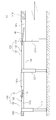
- FIG. 3 is a view schematically showing a state in which the automatically deployable beekeeping device according to an embodiment of the present invention is deployed.
- FIG. 4 is a plan view schematically showing a state in which an automatically deployable beekeeping device according to an embodiment of the present invention is deployed.
- FIG. 5 is a view schematically showing a state in which a beekeeper shelf is installed in an automatically deployable beekeeping device according to an embodiment of the present invention.
- a "module” or “unit” for a component used in the present specification performs at least one function or operation.
- the "module” or “unit” may perform a function or operation by hardware, software, or a combination of hardware and software.
- a plurality of “modules” or a plurality of “units” excluding “module” or “unit” to be performed in specific hardware or performed by at least one processor may be integrated into at least one module.
- Singular expressions include plural expressions unless the context clearly indicates otherwise.
- FIG. 2 is a schematic view showing a folded state of an automatically deployable beekeeping device according to an embodiment of the present invention
- FIG. 3 is a view schematically showing an unfolded state of an automatically deployable beekeeping device according to an embodiment of the present invention
- 4 is a plan view schematically showing a state in which an auto-deployable beekeeping device according to an embodiment of the present invention is deployed
- FIG. 5 is a state in which a beekeeper shelf is installed in the auto-deployable beekeeping device according to an embodiment of the present invention It is a diagram schematically showing.
- an automatically deployable beekeeping apparatus 100 includes a bottom portion 110 installed on the loading portion 210 of the vehicle 200.
- the bottom part 110 is formed in a square panel structure and is installed on the loading part 210 of the vehicle 200, and on one side, there is a space in which the beekeeper shelf 180 can be mounted, and a number of beekeepers for beekeeping operations
- a moving path may be formed to move between the shelves 180, and a shelf frame 120 to be described later may be rotatably supported on the side.
- a frame disposed in a lattice structure to support the upper panel may be further provided under the bottom portion 110, and the panel provided on the upper side of the frame includes the shelf frame 120 ) Is stacked in multiple layers along the vertical direction in a folded state, and in a state in which the shelf frame 120 is deployed, the shelf frame 120 slides in the unfolded direction to form a telescope structure capable of expanding the area.
- a frame supporting a plurality of panels stacked in multiple layers is provided with a guide rail to guide the movement of the plurality of panels, and a plurality of panels installed on the guide rail can be automatically deployed and folded by being connected to a separate withdrawal device. have.
- the automatic deployable beekeeping device 100 includes a shelf frame 120.
- the shelf frame 120 is rotatably coupled to both ends of the bottom unit 110, and is unfolded or folded according to the driving of the first driving unit 140 to be described later. fold).
- the shelf frame 120 is rotatably coupled to the side end of the bottom unit 110 through a separate hinge means, and a first link unit 130 to be described later according to the driving of the first driving unit 140 It is developed outwardly or folded inwardly by receiving a force from it.
- the shelf frame 120 is arranged in a state parallel to the bottom portion 110 when deployed as shown in FIG. 3, and is perpendicular to the bottom portion 110 when folded as shown in FIG. It is placed in a state.
- the shelf frame 120 includes a lattice structure frame (not shown) rotatably coupled to the end of the bottom portion 110 through a separate hinge means, and a panel (not shown) surrounding the outer surface of the frame. I can.
- a first load support unit 121 that is supported on the ground and supports the shelf frame 120 is provided. It may be further provided.
- the first load supporting part 121 may be fixed in a state perpendicular to the second main link member 132.
- the first load supporting part 121 may be fixed to a portion of the second main link member 132 adjacent to the shelf frame 120. Accordingly, the first load support portion 121 may be disposed vertically with respect to the ground when the shelf frame 120 is rotated to be in a parallel state with respect to the support portion 110.
- first load support portion 121 may be formed in a structure that can be stretched.
- the first load support portion 121 is a main body fixed to the second main link member 132, and is installed so as to protrude to the main body to increase the total length of the first load support portion 121 It may include an extension rod that extends or contracts, a support plate that is coupled to an end of the extension rod and is rotatable according to an inclination of the ground, and a support plate supported on the ground, and a driving means for controlling movement of the extension rod.
- the first load support 121 is extended by a preset length and supported on the ground, through which the second main link member ( By distributing the load acting in the vertical direction on the 132 and the shelf frame 120 to the ground, deformation and damage of the shelf frame 120 may be prevented.
- the automatically deployable beekeeping device 100 includes a first link unit 130.
- the first link unit 130 connects the bottom unit 110 and the shelf frame 120 to each other, and when the shelf frame 120 is folded, it can be bent at a predetermined angle. It consists of at least one joint structure.
- first link unit 130 may arrange the shelf frame 120 in a vertical or horizontal state through an external force transmitted through the first driving unit 140 to be described later.
- the shelf frame 120 when the first link unit 130 is bent into the inside of the shelf frame 120 through an external force transmitted through the first driving unit 140, the shelf frame 120 is folded to form the shelf frame 120.
- the shelf frame 120 When the shelf frame 120 is maintained in a vertical state and is expanded to the outside of the shelf frame 120, the shelf frame 120 may be expanded to maintain the shelf frame 120 in a horizontal state.
- the first link unit 130 will be described in detail.
- the first link unit 130 may include a first main link member 131, a second main link member 132, and a first hinge means 133.
- first main link member 131 is rotatably coupled to the bottom portion 110 through the first hinge means 133, and the other side is rotatably coupled to the second main link member 132.
- the second main link member 132 is rotatably coupled to the shelf frame 120 on one side through the first hinge means 133 and the other side rotatably to the first main link member 131 Can be combined.
- each of the first main link member 131 and the second main link member 132 has a through hole through which the first hinge means 133 can penetrate into one side and the other side, and has a rod shape having a preset length. Can be formed.
- the first hinge means 133 is formed in a pin shape, and the bottom portion 110 and the first main link member 131, the shelf frame 120 and the second main link member 132 and the first main link member ( 131) and the second main link member 132, the bottom portion 110 and the first main link member 131, the shelf frame 120 and the second main link member 132, and the first main link member ( 131 and the second main link member 132 may be connected to each other.
- the first link unit 130 when the first link unit 130 is bent inward of the shelf frame 120, the first main link member 131 is disposed parallel to the shelf frame 120 disposed in a vertical state, and the first The second main link member 132 rotatably coupled to the main link member 131 may be disposed in parallel with the bottom portion 110.
- the first link unit 130 when the first link unit 130 is deployed to the outside of the shelf frame 120, the first main link member 131 and the second main link member 132 are the shelf frame 120 disposed in a horizontal state. It can be arranged parallel to.
- the auto-deployable beekeeping device 100 includes a first driving unit 140.
- the first driving unit 140 connects the bottom unit 110 and the first link unit 130 to each other, and is rotatable together with the first link unit 130, but a structure capable of being stretchable. Is formed by Accordingly, the first driving unit 140 rotates the first link unit 130 in one direction or the other direction by applying a pushing or pulling force to the first link unit 130 through extension or contraction, 1
- the shelf frame 120 connected to the link unit 130 is rotated and disposed in a vertical or horizontal state.
- first driving unit 140 may be rotatably coupled to the bottom portion 110 and the other side may be rotatably coupled to the first main link member 131.
- first driving unit 140 may be formed of an expandable hydraulic cylinder. Therefore, when the first driving unit 140 is elongated, it transmits a pushing force to the first main link member 131 and rotates together with the first main link member 131 in one direction, through which the shelf frame 120 is moved. It may be disposed vertically with respect to the bottom part 110.
- the first driving unit 140 transmits a pulling force to the first main link member 131 to rotate in the other direction together with the first main link member 131, and thereby, the shelf frame 120 It may be arranged in a parallel state with respect to the bottom part 110.
- the first driving unit 140 is not necessarily formed of a hydraulic cylinder, and may be changed and applied in various forms within a condition capable of performing the same function.
- the automatically deployable beekeeping device 100 may further include an extension frame 150, a second link unit 160 and a second driving unit 170.
- the extension frame 150 is rotatably coupled to the end of each shelf frame 120 provided in plural, and is expanded or folded according to the driving of the second driving unit 170 to be described later. Can be.
- extension frame 150 is rotatably coupled to the end of each shelf frame 120 through a separate hinge means, and a second link unit 160 to be described later according to the driving of the second driving unit 170 It may be deployed outwardly or folded inwardly by receiving a force from it.
- the extension frame 150 is disposed in a parallel state with respect to the shelf frame 120 when deployed as shown in FIG. 3, and is perpendicular to the shelf frame 120 when folded as shown in FIG. Can be placed in the state.
- the extension frame 150 may include a frame having a lattice structure rotatably coupled to an end of the shelf frame 120 through a separate hinge means, and a panel surrounding the outer surface of the frame.
- a second load support unit 151 that is supported on the ground and supports the extension frame 150 is provided. It may be further provided.
- the second load support part 151 may be fixed in a state perpendicular to the second auxiliary link member 162. Therefore, when the second load support part 151 is rotated so that the extension frame 150 is parallel to the shelf frame 120 in a state in which the shelf frame 120 is disposed parallel to the bottom part 110 It can be placed perpendicular to the ground.
- the second load support part 151 may be formed in a stretchable structure.
- the second load support part 151 is rotatably installed on the outer surface of the extension frame 150, and the second load support part 151 is installed so as to appear and protrude in the main body. It may include an extension rod that extends or contracts the length, a support plate that is coupled to an end of the extension rod and is rotatable according to the slope of the ground, and a support plate supported on the ground, and a driving means for controlling the movement of the extension rod. .
- the second link unit 160 connects the shelf frame 120 and the extension frame 150 to each other, and includes at least one joint structure to be bent at a predetermined angle when the extension frame 150 is folded. do.
- the second link unit 160 may arrange the extension frame 150 in a vertical or horizontal state with respect to the shelf frame 120 through an external force transmitted through the second driving unit 170 to be described later.
- the extension frame 150 is folded to form the extension frame 150.
- the extension frame 150 is maintained in a vertical state with respect to the shelf frame 120, and when the extension frame 150 is expanded, the extension frame 150 is expanded to maintain the extension frame 150 in a horizontal state with respect to the shelf frame 120 I can make it.
- the second link unit 160 will be described in detail.
- the second link unit 160 may include a first auxiliary link member 161, a second auxiliary link member 162, and a second hinge means 163.
- first auxiliary link member 161 is rotatably coupled to the shelf frame 120 through the second hinge means 163, and the other side is rotatably coupled to the second auxiliary link member 162.
- second auxiliary link member 162 is rotatably coupled to the extension frame 150 on one side through the second hinge means 163, and the other side is rotatable to the first auxiliary link member 161.
- each of the first auxiliary link member 161 and the second auxiliary link member 162 has a through hole through which the second hinge means 163 can penetrate at one side and the other side, and has a rod shape having a preset length. Can be formed.
- the second hinge means 163 is formed in a pin shape, and the shelf frame 120 and the first auxiliary link member 161, the extension frame 150 and the second auxiliary link member 162 and the first auxiliary link member ( 161 and the second auxiliary link member 162 through the shelf frame 120 and the first auxiliary link member 161, the extension frame 150 and the second auxiliary link member 162 and the first auxiliary link member ( 161 and the second auxiliary link member 162 may be connected to each other.
- the first auxiliary link member 161 is with respect to the extension frame 150 disposed in a vertical state with respect to the shelf frame 120
- the second auxiliary link member 162 is disposed in parallel and rotatably coupled to the first auxiliary link member 161 may be disposed parallel to the shelf frame 120.
- the first auxiliary link member 161 and the second auxiliary link member 162 are in a horizontal state with respect to the shelf frame 120. Can be placed.
- the second driving unit 170 connects the shelf frame 120 and the second link unit 160 to each other, and is rotatable together with the second link unit 160, but is formed in a stretchable structure. Accordingly, the second driving unit 170 rotates the second link unit 160 in one direction or the other direction by applying a pushing or pulling force to the second link unit 160 through extension or contraction. 2 By rotating the extension frame 150 connected to the link unit 160 is arranged in a vertical or horizontal state.
- one side of the second driving unit 170 may be rotatably coupled to the shelf frame 120 and the other side may be rotatably coupled to the first auxiliary link member 161.
- the second driving unit 170 may be formed of an expandable hydraulic cylinder. Accordingly, when the second driving unit 170 is elongated, the second driving unit 170 transmits a pushing force to the first auxiliary link member 161 and rotates together with the first auxiliary link member 161 in one direction, thereby forming the extension frame 150. It can be arranged in a vertical state with respect to the shelf frame 120.
- the second driving unit 170 when the second driving unit 170 is contracted, the second driving unit 170 transmits a pulling force to the first auxiliary link member 161 and rotates in the other direction together with the first auxiliary link member 161, through which the extension frame 150 is moved. It can be arranged in a parallel state with respect to the shelf frame 120.
- the second driving unit 170 is not necessarily formed as a hydraulic cylinder, and may be changed and applied in various forms within conditions capable of performing the same function.
- the first link part 130 And a receiving groove 100a capable of accommodating the second link unit 160 may be formed.
- the auto-deployable beekeeping device 100 may further include a beekeeper shelf 180.
- the beekeeping shelf 180 accommodates the beekeeping container 181 on the inside, and is seated on the upper surface of the bottom part 110, or separately on the inside of the shelf frame 120 and the extension frame 150 It may be rotatably coupled through the hinge means of.
- the beekeeper shelf 180 rotates around the hinge means when the shelf frame 120 and the extension frame 150 are rotated to keep the beekeeper 181 in a vertical state with respect to the bottom part 110 at all times. I can.
- the beekeeping shelf 180 may include a support plate, a pair of support pieces provided at the front and rear ends of the support plate, and a mounting support bar coupled to the pair of support pieces.
- the hinge means for rotatably supporting the beekeeper shelf 180 may be formed of a bracket having a "c" shape.
- the beekeeping device 100 that can be automatically folded and deployed through a plurality of link units and a plurality of driving units, so that the work efficiency and convenience of the user are significantly improved compared to the conventional beekeeping container. And installation and withdrawal can be performed quickly, and further, repetitive work is eliminated, and the cost can be significantly reduced by minimizing manpower required for work.
Landscapes
- Engineering & Computer Science (AREA)
- Life Sciences & Earth Sciences (AREA)
- Environmental Sciences (AREA)
- Transportation (AREA)
- Mechanical Engineering (AREA)
- Animal Husbandry (AREA)
- Biodiversity & Conservation Biology (AREA)
- Health & Medical Sciences (AREA)
- Public Health (AREA)
- Tents Or Canopies (AREA)
Abstract
La présente invention concerne, selon un mode de réalisation, un appareil d'apiculture dépliable automatiquement comprenant : une partie inférieure installée dans une unité de chargement d'un véhicule ; un cadre d'étagère accouplé rotatif à une partie extrémité de la partie inférieure ; une première partie de liaison conçue pour relier la partie inférieure et le cadre d'étagère l'un à l'autre, lorsque le cadre d'étagère est plié, la première partie de liaison étant pliée vers l'intérieur du cadre d'étagère et supportant le cadre d'étagère tandis que le cadre d'étagère est placé verticalement, et lorsque le cadre d'étagère est déplié, la première partie de liaison étant dépliée vers l'extérieur du cadre d'étagère et supportant le cadre d'étagère tandis que le cadre d'étagère est placé horizontalement ; et une première unité d'entraînement conçue pour relier la partie inférieure et la première partie de liaison l'une à l'autre, et faire tourner la première partie de liaison dans une direction ou dans une autre direction de telle sorte que le cadre d'étagère relié à la première partie de liaison est disposé verticalement ou horizontalement. Selon un mode de réalisation de la présente invention, un appareil d'apiculture pliable et dépliable automatiquement peut être obtenu par une pluralité de parties de liaison et une pluralité d'unités d'entraînement. Par conséquent, l'efficacité de travail et la commodité pour un utilisateur peuvent être considérablement améliorées par rapport à un conteneur d'apiculture classique, l'installation et le démontage peuvent être effectués rapidement et, en outre, les coûts peuvent être significativement réduits en éliminant un travail répétitif et en réduisant au minimum la main-d'œuvre requise pour le travail.
Priority Applications (1)
| Application Number | Priority Date | Filing Date | Title |
|---|---|---|---|
| US17/420,140 US11812729B2 (en) | 2019-03-14 | 2020-03-05 | Automatically unfoldable beekeeping apparatus |
Applications Claiming Priority (2)
| Application Number | Priority Date | Filing Date | Title |
|---|---|---|---|
| KR10-2019-0029508 | 2019-03-14 | ||
| KR1020190029508A KR102064701B1 (ko) | 2019-03-14 | 2019-03-14 | 자동 전개 가능한 양봉 장치 |
Publications (1)
| Publication Number | Publication Date |
|---|---|
| WO2020184896A1 true WO2020184896A1 (fr) | 2020-09-17 |
Family
ID=69154781
Family Applications (1)
| Application Number | Title | Priority Date | Filing Date |
|---|---|---|---|
| PCT/KR2020/003102 Ceased WO2020184896A1 (fr) | 2019-03-14 | 2020-03-05 | Appareil d'apiculture dépliable automatiquement |
Country Status (3)
| Country | Link |
|---|---|
| US (1) | US11812729B2 (fr) |
| KR (1) | KR102064701B1 (fr) |
| WO (1) | WO2020184896A1 (fr) |
Families Citing this family (2)
| Publication number | Priority date | Publication date | Assignee | Title |
|---|---|---|---|---|
| KR102064701B1 (ko) * | 2019-03-14 | 2020-01-09 | 오옥남 | 자동 전개 가능한 양봉 장치 |
| KR102682229B1 (ko) * | 2021-11-16 | 2024-07-04 | 강원대학교산학협력단 | 양봉 사양 관리용 다기능 운반차 |
Citations (6)
| Publication number | Priority date | Publication date | Assignee | Title |
|---|---|---|---|---|
| JP2767195B2 (ja) * | 1993-12-16 | 1998-06-18 | 有限会社戸谷建設工業 | ダンプカーのリアドア開閉装置 |
| KR101218244B1 (ko) * | 2010-12-06 | 2013-01-08 | 유운모 | 차량의 적재함도어 개폐장치 |
| KR101423327B1 (ko) * | 2012-07-10 | 2014-07-25 | 박중수 | 차량 이동식 양봉장치 |
| CN107006402A (zh) * | 2017-05-31 | 2017-08-04 | 巫溪县显述蜜蜂养殖有限公司 | 一种外摆式养蜂移动平台 |
| US20180220627A1 (en) * | 2013-11-19 | 2018-08-09 | Charles Linder | Stackable package and system for holding and transporting honeybees |
| KR102064701B1 (ko) * | 2019-03-14 | 2020-01-09 | 오옥남 | 자동 전개 가능한 양봉 장치 |
Family Cites Families (7)
| Publication number | Priority date | Publication date | Assignee | Title |
|---|---|---|---|---|
| US2470360A (en) * | 1946-05-28 | 1949-05-17 | Kirwan Y Messick | Lumber loading truck |
| US2451275A (en) * | 1947-01-30 | 1948-10-12 | John M Cercownay | Table assembly for automobiles |
| US5772270A (en) * | 1995-08-04 | 1998-06-30 | Hwh Corporation | Pivotal extension apparatus for motor homes and recreational vehicles |
| US7222905B2 (en) * | 2003-04-04 | 2007-05-29 | Edward Jaeck | Reconfigurable truck bed or vehicle body |
| US7506909B2 (en) * | 2007-03-09 | 2009-03-24 | Barnes Wilbert E | Expandable truck bed |
| US8590962B2 (en) * | 2011-01-28 | 2013-11-26 | Lifetime Products, Inc. | Trailer with multi-position panels |
| CN105379645B (zh) * | 2015-10-27 | 2017-10-10 | 王东文 | 一种展开式养蜂平台 |
-
2019
- 2019-03-14 KR KR1020190029508A patent/KR102064701B1/ko not_active Expired - Fee Related
-
2020
- 2020-03-05 US US17/420,140 patent/US11812729B2/en active Active
- 2020-03-05 WO PCT/KR2020/003102 patent/WO2020184896A1/fr not_active Ceased
Patent Citations (6)
| Publication number | Priority date | Publication date | Assignee | Title |
|---|---|---|---|---|
| JP2767195B2 (ja) * | 1993-12-16 | 1998-06-18 | 有限会社戸谷建設工業 | ダンプカーのリアドア開閉装置 |
| KR101218244B1 (ko) * | 2010-12-06 | 2013-01-08 | 유운모 | 차량의 적재함도어 개폐장치 |
| KR101423327B1 (ko) * | 2012-07-10 | 2014-07-25 | 박중수 | 차량 이동식 양봉장치 |
| US20180220627A1 (en) * | 2013-11-19 | 2018-08-09 | Charles Linder | Stackable package and system for holding and transporting honeybees |
| CN107006402A (zh) * | 2017-05-31 | 2017-08-04 | 巫溪县显述蜜蜂养殖有限公司 | 一种外摆式养蜂移动平台 |
| KR102064701B1 (ko) * | 2019-03-14 | 2020-01-09 | 오옥남 | 자동 전개 가능한 양봉 장치 |
Also Published As
| Publication number | Publication date |
|---|---|
| US11812729B2 (en) | 2023-11-14 |
| KR102064701B1 (ko) | 2020-01-09 |
| US20220079122A1 (en) | 2022-03-17 |
Similar Documents
| Publication | Publication Date | Title |
|---|---|---|
| WO2020184896A1 (fr) | Appareil d'apiculture dépliable automatiquement | |
| US20220181859A1 (en) | Cable laying device | |
| USRE44758E1 (en) | Optical fiber interconnect cabinets, termination modules and fiber connectivity management for the same | |
| ITUA20164436A1 (it) | "Cella di robot" | |
| WO2005108877B1 (fr) | Installation transportable de production d'energie solaire | |
| WO2014133330A1 (fr) | Appareil d'ouverture de boîtes intégré au bâti dans un appareil de fabrication de cartonnages | |
| WO2015126015A1 (fr) | Structure de tente pour toit | |
| US5278742A (en) | Automated truss module | |
| US11239792B2 (en) | Deployable solar tracker system | |
| ITRM20010181U1 (it) | Perfezionato modulo di terminazione per cavi di fibre ottiche. | |
| US5432691A (en) | Automated truss module with deployment mechanism | |
| WO2019009457A1 (fr) | Conteneur pliable | |
| WO2015190626A1 (fr) | Rambarde destinée à un équipement de construction | |
| CN114319384B (zh) | 一种防止基坑塌陷的应急支撑设备 | |
| US2833540A (en) | Stacking device for printing and the like machines | |
| WO2025037768A1 (fr) | Support de moyeu et système de traitement de plantes le comprenant | |
| WO2011083891A1 (fr) | Appareil de transfert de bobines | |
| WO2022030700A1 (fr) | Plateforme de travail élévatrice | |
| PL70704Y1 (pl) | Kombajn do zbioru wiśni i innych owoców z automatycznie rozwijanym i zwijanym ekranem | |
| WO2018139872A1 (fr) | Conteneur pour apiculture | |
| CN211287544U (zh) | 一种可调节指梁及可调节指梁系统 | |
| CN206108542U (zh) | 具有防尘防潮防雨功能的电力电缆存储装置 | |
| WO2020209663A1 (fr) | Conteneur multi-bâtis intelligent | |
| WO2022219949A1 (fr) | Râtelier de stockage | |
| WO2014088141A1 (fr) | Serre en vinyle à isolation multiple triangulaire |
Legal Events
| Date | Code | Title | Description |
|---|---|---|---|
| 121 | Ep: the epo has been informed by wipo that ep was designated in this application |
Ref document number: 20770848 Country of ref document: EP Kind code of ref document: A1 |
|
| NENP | Non-entry into the national phase |
Ref country code: DE |
|
| 122 | Ep: pct application non-entry in european phase |
Ref document number: 20770848 Country of ref document: EP Kind code of ref document: A1 |