WO2020184896A1 - Automatically unfoldable beekeeping apparatus - Google Patents
Automatically unfoldable beekeeping apparatus Download PDFInfo
- Publication number
- WO2020184896A1 WO2020184896A1 PCT/KR2020/003102 KR2020003102W WO2020184896A1 WO 2020184896 A1 WO2020184896 A1 WO 2020184896A1 KR 2020003102 W KR2020003102 W KR 2020003102W WO 2020184896 A1 WO2020184896 A1 WO 2020184896A1
- Authority
- WO
- WIPO (PCT)
- Prior art keywords
- shelf frame
- link member
- frame
- shelf
- beekeeping
- Prior art date
- Legal status (The legal status is an assumption and is not a legal conclusion. Google has not performed a legal analysis and makes no representation as to the accuracy of the status listed.)
- Ceased
Links
Images


Classifications
-
- A—HUMAN NECESSITIES
- A01—AGRICULTURE; FORESTRY; ANIMAL HUSBANDRY; HUNTING; TRAPPING; FISHING
- A01K—ANIMAL HUSBANDRY; AVICULTURE; APICULTURE; PISCICULTURE; FISHING; REARING OR BREEDING ANIMALS, NOT OTHERWISE PROVIDED FOR; NEW BREEDS OF ANIMALS
- A01K51/00—Appliances for treating beehives or parts thereof, e.g. for cleaning or disinfecting
-
- A—HUMAN NECESSITIES
- A01—AGRICULTURE; FORESTRY; ANIMAL HUSBANDRY; HUNTING; TRAPPING; FISHING
- A01K—ANIMAL HUSBANDRY; AVICULTURE; APICULTURE; PISCICULTURE; FISHING; REARING OR BREEDING ANIMALS, NOT OTHERWISE PROVIDED FOR; NEW BREEDS OF ANIMALS
- A01K49/00—Rearing-boxes; Queen transporting or introducing cages
-
- A—HUMAN NECESSITIES
- A01—AGRICULTURE; FORESTRY; ANIMAL HUSBANDRY; HUNTING; TRAPPING; FISHING
- A01K—ANIMAL HUSBANDRY; AVICULTURE; APICULTURE; PISCICULTURE; FISHING; REARING OR BREEDING ANIMALS, NOT OTHERWISE PROVIDED FOR; NEW BREEDS OF ANIMALS
- A01K55/00—Bee-smokers; Bee-keepers' accessories, e.g. veils
-
- B—PERFORMING OPERATIONS; TRANSPORTING
- B60—VEHICLES IN GENERAL
- B60P—VEHICLES ADAPTED FOR LOAD TRANSPORTATION OR TO TRANSPORT, TO CARRY, OR TO COMPRISE SPECIAL LOADS OR OBJECTS
- B60P1/00—Vehicles predominantly for transporting loads and modified to facilitate loading, consolidating the load, or unloading
- B60P1/04—Vehicles predominantly for transporting loads and modified to facilitate loading, consolidating the load, or unloading with a tipping movement of load-transporting element
- B60P1/16—Vehicles predominantly for transporting loads and modified to facilitate loading, consolidating the load, or unloading with a tipping movement of load-transporting element actuated by fluid-operated mechanisms
- B60P1/20—Vehicles predominantly for transporting loads and modified to facilitate loading, consolidating the load, or unloading with a tipping movement of load-transporting element actuated by fluid-operated mechanisms with toothed gears, wheels, or sectors; with links, cams and rollers, or the like
-
- B—PERFORMING OPERATIONS; TRANSPORTING
- B60—VEHICLES IN GENERAL
- B60P—VEHICLES ADAPTED FOR LOAD TRANSPORTATION OR TO TRANSPORT, TO CARRY, OR TO COMPRISE SPECIAL LOADS OR OBJECTS
- B60P3/00—Vehicles adapted to transport, to carry or to comprise special loads or objects
-
- B—PERFORMING OPERATIONS; TRANSPORTING
- B60—VEHICLES IN GENERAL
- B60P—VEHICLES ADAPTED FOR LOAD TRANSPORTATION OR TO TRANSPORT, TO CARRY, OR TO COMPRISE SPECIAL LOADS OR OBJECTS
- B60P3/00—Vehicles adapted to transport, to carry or to comprise special loads or objects
- B60P3/04—Vehicles adapted to transport, to carry or to comprise special loads or objects for transporting animals
Definitions
- the present invention relates to an automatically deployable beekeeping device.
- Beekeeping is an operation to obtain honey by farming bees, and more specifically, it means that bees build beehives on a number of cows placed in the beehive and obtain honey from these beehives.
- the beekeeping operation allows the bees to collect nectar by moving and installing the beehive to the place where the flowers bloom at the time of flowering of a honeycomb plant, that is, a flower capable of picking nectar.
- a mobile vehicle having a loading space capable of loading a beekeeper is indispensable, and through this, the operator quickly moves to an area where beekeeping is possible and performs the beekeeping operation at a desired place.
- a conventional beekeeping container includes a shelf frame 20 rotatably coupled to a container body 10 and a shelf frame 20 rotatably coupled to the shelf frame 20.
- the beekeeper (2) including the beekeeper shelf (30) that is always erected in the vertical direction when it is unfolded or erected, it is folded to maintain the box structure like a container, and conversely, the beekeeper (2) When it is necessary to install it, it is deployed to maintain a flat structure.
- a number of beekeeping containers 2 can be stably loaded, as well as when changing the beekeeping location or arriving at the beekeeping location, the worker can manually drop the beekeeping container 2 on the vehicle or from the vehicle.
- the present invention was conceived to solve the above problems, and an object of the present invention is to automatically expand and fold a shelf frame, thereby improving work efficiency and convenience of users, and further reducing costs. It is to provide a deployable beekeeping device.
- Another object of the present invention is to provide an automatically deployable beekeeping device capable of stably supporting a folded shelf frame even without a separate support frame.
- An automatically deployable beekeeping device for solving the above problem includes: a bottom portion installed in a loading portion of a vehicle; A shelf frame rotatably coupled to an end of the bottom portion; The bottom part and the shelf frame are connected to each other, and when the shelf frame is folded, the shelf frame is bent to the inside of the shelf frame to support the shelf frame disposed in a vertical state, and when the shelf frame is deployed, to the outside of the shelf frame.
- a first link unit configured to support the shelf frame deployed and disposed in a horizontal state; And a first link configured to connect the bottom part and the first link part to each other, and to rotate the first link part in one direction or the other direction to arrange the shelf frame connected to the first link part in a vertical or horizontal state.
- 1 driving unit includes.
- the first link part may include a first main link member rotatably coupled to the bottom part; One side is rotatably coupled to the shelf frame, the other side is a second main link member rotatably coupled to the first main link member; And first hinge means for connecting the bottom portion and the first main link member, the shelf frame and the second main link member, and the first main link member and the second main link member. It may include.
- the first main link member When the first link part is bent inward of the shelf frame, the first main link member may be disposed parallel to the shelf frame, and the second main link member may be disposed parallel to the bottom part. .
- the first driving part is rotated in one direction together with the first main link member during extension to arrange the shelf frame in a vertical state with respect to the bottom part, and in the other direction together with the first main link member when contracted. It may be formed as a hydraulic cylinder that is rotated to arrange the shelf frame in a parallel state with respect to the bottom part.
- the load that is supported on the ground and acts in a vertical direction on the shelf frame is distributed to the ground. It may further include a; first load support configured to be.
- An extension frame rotatably coupled to an end of the shelf frame;
- the shelf frame and the extension frame are connected to each other, and when the extension frame is folded, the extension frame is bent to the inside of the extension frame to support the extension frame disposed in a horizontal state, and when the extension frame is unfolded, to the outside of the extension frame
- a second link unit configured to support the extended frame that is deployed and arranged in a vertical state;
- a second link configured to connect the shelf frame and the second link unit to each other, and to rotate the second link unit in one direction or the other direction to arrange the extension frame connected to the second link unit in a horizontal or vertical state.
- 2 driving unit may further include.
- the second link unit may include a first auxiliary link member rotatably coupled to the shelf frame; One side is rotatably coupled to the extension frame, the other side is a second auxiliary link member rotatably coupled to the first auxiliary link member; And second hinge means for connecting the shelf frame and the first auxiliary link member, the extension frame and the second auxiliary link member, and the first auxiliary link member and the second auxiliary link member.
- the first auxiliary link member When the second link part is bent inward of the extension frame, the first auxiliary link member may be disposed parallel to the extension frame, and the second auxiliary link member may be disposed parallel to the shelf frame. .
- the second driving part is rotated in one direction together with the first auxiliary link member during extension to arrange the extension frame in a vertical state with respect to the shelf frame, and when contracted, in the other direction together with the first auxiliary link member.
- It may be formed as a hydraulic cylinder which is rotated to arrange the extension frame in a parallel state with respect to the shelf frame.
- the load that is supported on the ground and acts in a vertical direction on the extension frame is distributed to the ground. It may further include a; second load support configured to be.
- a receiving groove for accommodating the first link portion and the second link portion may be formed.
- It may further include a beekeeper shelf that accommodates the beekeeper inside, is rotatably coupled to the inside of the shelf frame and the extension frame, and is configured to keep the beekeeper in a vertical state at all times.
- a beekeeping device that can be automatically folded and deployed through a plurality of link units and a plurality of driving units, it is possible to significantly improve the work efficiency and convenience of the user compared to the conventional beekeeping container, Installation and withdrawal can be performed quickly, and further, by eliminating repetitive work and minimizing manpower required for work, cost can be significantly reduced.
- shelf frame can be stably supported through a plurality of link units and a plurality of driving units without having a separate support frame, manufacturing costs can be reduced, and beekeeping operations by loading a larger amount of beekeepers Can increase the productivity of
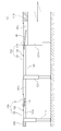
- 1 is a view showing a conventional beekeeping container.
- FIG. 2 is a view schematically showing a folded state of the automatically deployable beekeeping device according to an embodiment of the present invention.
- FIG. 3 is a view schematically showing a state in which the automatically deployable beekeeping device according to an embodiment of the present invention is deployed.
- FIG. 4 is a plan view schematically showing a state in which an automatically deployable beekeeping device according to an embodiment of the present invention is deployed.
- FIG. 5 is a view schematically showing a state in which a beekeeper shelf is installed in an automatically deployable beekeeping device according to an embodiment of the present invention.
- a "module” or “unit” for a component used in the present specification performs at least one function or operation.
- the "module” or “unit” may perform a function or operation by hardware, software, or a combination of hardware and software.
- a plurality of “modules” or a plurality of “units” excluding “module” or “unit” to be performed in specific hardware or performed by at least one processor may be integrated into at least one module.
- Singular expressions include plural expressions unless the context clearly indicates otherwise.
- FIG. 2 is a schematic view showing a folded state of an automatically deployable beekeeping device according to an embodiment of the present invention
- FIG. 3 is a view schematically showing an unfolded state of an automatically deployable beekeeping device according to an embodiment of the present invention
- 4 is a plan view schematically showing a state in which an auto-deployable beekeeping device according to an embodiment of the present invention is deployed
- FIG. 5 is a state in which a beekeeper shelf is installed in the auto-deployable beekeeping device according to an embodiment of the present invention It is a diagram schematically showing.
- an automatically deployable beekeeping apparatus 100 includes a bottom portion 110 installed on the loading portion 210 of the vehicle 200.
- the bottom part 110 is formed in a square panel structure and is installed on the loading part 210 of the vehicle 200, and on one side, there is a space in which the beekeeper shelf 180 can be mounted, and a number of beekeepers for beekeeping operations
- a moving path may be formed to move between the shelves 180, and a shelf frame 120 to be described later may be rotatably supported on the side.
- a frame disposed in a lattice structure to support the upper panel may be further provided under the bottom portion 110, and the panel provided on the upper side of the frame includes the shelf frame 120 ) Is stacked in multiple layers along the vertical direction in a folded state, and in a state in which the shelf frame 120 is deployed, the shelf frame 120 slides in the unfolded direction to form a telescope structure capable of expanding the area.
- a frame supporting a plurality of panels stacked in multiple layers is provided with a guide rail to guide the movement of the plurality of panels, and a plurality of panels installed on the guide rail can be automatically deployed and folded by being connected to a separate withdrawal device. have.
- the automatic deployable beekeeping device 100 includes a shelf frame 120.
- the shelf frame 120 is rotatably coupled to both ends of the bottom unit 110, and is unfolded or folded according to the driving of the first driving unit 140 to be described later. fold).
- the shelf frame 120 is rotatably coupled to the side end of the bottom unit 110 through a separate hinge means, and a first link unit 130 to be described later according to the driving of the first driving unit 140 It is developed outwardly or folded inwardly by receiving a force from it.
- the shelf frame 120 is arranged in a state parallel to the bottom portion 110 when deployed as shown in FIG. 3, and is perpendicular to the bottom portion 110 when folded as shown in FIG. It is placed in a state.
- the shelf frame 120 includes a lattice structure frame (not shown) rotatably coupled to the end of the bottom portion 110 through a separate hinge means, and a panel (not shown) surrounding the outer surface of the frame. I can.
- a first load support unit 121 that is supported on the ground and supports the shelf frame 120 is provided. It may be further provided.
- the first load supporting part 121 may be fixed in a state perpendicular to the second main link member 132.
- the first load supporting part 121 may be fixed to a portion of the second main link member 132 adjacent to the shelf frame 120. Accordingly, the first load support portion 121 may be disposed vertically with respect to the ground when the shelf frame 120 is rotated to be in a parallel state with respect to the support portion 110.
- first load support portion 121 may be formed in a structure that can be stretched.
- the first load support portion 121 is a main body fixed to the second main link member 132, and is installed so as to protrude to the main body to increase the total length of the first load support portion 121 It may include an extension rod that extends or contracts, a support plate that is coupled to an end of the extension rod and is rotatable according to an inclination of the ground, and a support plate supported on the ground, and a driving means for controlling movement of the extension rod.
- the first load support 121 is extended by a preset length and supported on the ground, through which the second main link member ( By distributing the load acting in the vertical direction on the 132 and the shelf frame 120 to the ground, deformation and damage of the shelf frame 120 may be prevented.
- the automatically deployable beekeeping device 100 includes a first link unit 130.
- the first link unit 130 connects the bottom unit 110 and the shelf frame 120 to each other, and when the shelf frame 120 is folded, it can be bent at a predetermined angle. It consists of at least one joint structure.
- first link unit 130 may arrange the shelf frame 120 in a vertical or horizontal state through an external force transmitted through the first driving unit 140 to be described later.
- the shelf frame 120 when the first link unit 130 is bent into the inside of the shelf frame 120 through an external force transmitted through the first driving unit 140, the shelf frame 120 is folded to form the shelf frame 120.
- the shelf frame 120 When the shelf frame 120 is maintained in a vertical state and is expanded to the outside of the shelf frame 120, the shelf frame 120 may be expanded to maintain the shelf frame 120 in a horizontal state.
- the first link unit 130 will be described in detail.
- the first link unit 130 may include a first main link member 131, a second main link member 132, and a first hinge means 133.
- first main link member 131 is rotatably coupled to the bottom portion 110 through the first hinge means 133, and the other side is rotatably coupled to the second main link member 132.
- the second main link member 132 is rotatably coupled to the shelf frame 120 on one side through the first hinge means 133 and the other side rotatably to the first main link member 131 Can be combined.
- each of the first main link member 131 and the second main link member 132 has a through hole through which the first hinge means 133 can penetrate into one side and the other side, and has a rod shape having a preset length. Can be formed.
- the first hinge means 133 is formed in a pin shape, and the bottom portion 110 and the first main link member 131, the shelf frame 120 and the second main link member 132 and the first main link member ( 131) and the second main link member 132, the bottom portion 110 and the first main link member 131, the shelf frame 120 and the second main link member 132, and the first main link member ( 131 and the second main link member 132 may be connected to each other.
- the first link unit 130 when the first link unit 130 is bent inward of the shelf frame 120, the first main link member 131 is disposed parallel to the shelf frame 120 disposed in a vertical state, and the first The second main link member 132 rotatably coupled to the main link member 131 may be disposed in parallel with the bottom portion 110.
- the first link unit 130 when the first link unit 130 is deployed to the outside of the shelf frame 120, the first main link member 131 and the second main link member 132 are the shelf frame 120 disposed in a horizontal state. It can be arranged parallel to.
- the auto-deployable beekeeping device 100 includes a first driving unit 140.
- the first driving unit 140 connects the bottom unit 110 and the first link unit 130 to each other, and is rotatable together with the first link unit 130, but a structure capable of being stretchable. Is formed by Accordingly, the first driving unit 140 rotates the first link unit 130 in one direction or the other direction by applying a pushing or pulling force to the first link unit 130 through extension or contraction, 1
- the shelf frame 120 connected to the link unit 130 is rotated and disposed in a vertical or horizontal state.
- first driving unit 140 may be rotatably coupled to the bottom portion 110 and the other side may be rotatably coupled to the first main link member 131.
- first driving unit 140 may be formed of an expandable hydraulic cylinder. Therefore, when the first driving unit 140 is elongated, it transmits a pushing force to the first main link member 131 and rotates together with the first main link member 131 in one direction, through which the shelf frame 120 is moved. It may be disposed vertically with respect to the bottom part 110.
- the first driving unit 140 transmits a pulling force to the first main link member 131 to rotate in the other direction together with the first main link member 131, and thereby, the shelf frame 120 It may be arranged in a parallel state with respect to the bottom part 110.
- the first driving unit 140 is not necessarily formed of a hydraulic cylinder, and may be changed and applied in various forms within a condition capable of performing the same function.
- the automatically deployable beekeeping device 100 may further include an extension frame 150, a second link unit 160 and a second driving unit 170.
- the extension frame 150 is rotatably coupled to the end of each shelf frame 120 provided in plural, and is expanded or folded according to the driving of the second driving unit 170 to be described later. Can be.
- extension frame 150 is rotatably coupled to the end of each shelf frame 120 through a separate hinge means, and a second link unit 160 to be described later according to the driving of the second driving unit 170 It may be deployed outwardly or folded inwardly by receiving a force from it.
- the extension frame 150 is disposed in a parallel state with respect to the shelf frame 120 when deployed as shown in FIG. 3, and is perpendicular to the shelf frame 120 when folded as shown in FIG. Can be placed in the state.
- the extension frame 150 may include a frame having a lattice structure rotatably coupled to an end of the shelf frame 120 through a separate hinge means, and a panel surrounding the outer surface of the frame.
- a second load support unit 151 that is supported on the ground and supports the extension frame 150 is provided. It may be further provided.
- the second load support part 151 may be fixed in a state perpendicular to the second auxiliary link member 162. Therefore, when the second load support part 151 is rotated so that the extension frame 150 is parallel to the shelf frame 120 in a state in which the shelf frame 120 is disposed parallel to the bottom part 110 It can be placed perpendicular to the ground.
- the second load support part 151 may be formed in a stretchable structure.
- the second load support part 151 is rotatably installed on the outer surface of the extension frame 150, and the second load support part 151 is installed so as to appear and protrude in the main body. It may include an extension rod that extends or contracts the length, a support plate that is coupled to an end of the extension rod and is rotatable according to the slope of the ground, and a support plate supported on the ground, and a driving means for controlling the movement of the extension rod. .
- the second link unit 160 connects the shelf frame 120 and the extension frame 150 to each other, and includes at least one joint structure to be bent at a predetermined angle when the extension frame 150 is folded. do.
- the second link unit 160 may arrange the extension frame 150 in a vertical or horizontal state with respect to the shelf frame 120 through an external force transmitted through the second driving unit 170 to be described later.
- the extension frame 150 is folded to form the extension frame 150.
- the extension frame 150 is maintained in a vertical state with respect to the shelf frame 120, and when the extension frame 150 is expanded, the extension frame 150 is expanded to maintain the extension frame 150 in a horizontal state with respect to the shelf frame 120 I can make it.
- the second link unit 160 will be described in detail.
- the second link unit 160 may include a first auxiliary link member 161, a second auxiliary link member 162, and a second hinge means 163.
- first auxiliary link member 161 is rotatably coupled to the shelf frame 120 through the second hinge means 163, and the other side is rotatably coupled to the second auxiliary link member 162.
- second auxiliary link member 162 is rotatably coupled to the extension frame 150 on one side through the second hinge means 163, and the other side is rotatable to the first auxiliary link member 161.
- each of the first auxiliary link member 161 and the second auxiliary link member 162 has a through hole through which the second hinge means 163 can penetrate at one side and the other side, and has a rod shape having a preset length. Can be formed.
- the second hinge means 163 is formed in a pin shape, and the shelf frame 120 and the first auxiliary link member 161, the extension frame 150 and the second auxiliary link member 162 and the first auxiliary link member ( 161 and the second auxiliary link member 162 through the shelf frame 120 and the first auxiliary link member 161, the extension frame 150 and the second auxiliary link member 162 and the first auxiliary link member ( 161 and the second auxiliary link member 162 may be connected to each other.
- the first auxiliary link member 161 is with respect to the extension frame 150 disposed in a vertical state with respect to the shelf frame 120
- the second auxiliary link member 162 is disposed in parallel and rotatably coupled to the first auxiliary link member 161 may be disposed parallel to the shelf frame 120.
- the first auxiliary link member 161 and the second auxiliary link member 162 are in a horizontal state with respect to the shelf frame 120. Can be placed.
- the second driving unit 170 connects the shelf frame 120 and the second link unit 160 to each other, and is rotatable together with the second link unit 160, but is formed in a stretchable structure. Accordingly, the second driving unit 170 rotates the second link unit 160 in one direction or the other direction by applying a pushing or pulling force to the second link unit 160 through extension or contraction. 2 By rotating the extension frame 150 connected to the link unit 160 is arranged in a vertical or horizontal state.
- one side of the second driving unit 170 may be rotatably coupled to the shelf frame 120 and the other side may be rotatably coupled to the first auxiliary link member 161.
- the second driving unit 170 may be formed of an expandable hydraulic cylinder. Accordingly, when the second driving unit 170 is elongated, the second driving unit 170 transmits a pushing force to the first auxiliary link member 161 and rotates together with the first auxiliary link member 161 in one direction, thereby forming the extension frame 150. It can be arranged in a vertical state with respect to the shelf frame 120.
- the second driving unit 170 when the second driving unit 170 is contracted, the second driving unit 170 transmits a pulling force to the first auxiliary link member 161 and rotates in the other direction together with the first auxiliary link member 161, through which the extension frame 150 is moved. It can be arranged in a parallel state with respect to the shelf frame 120.
- the second driving unit 170 is not necessarily formed as a hydraulic cylinder, and may be changed and applied in various forms within conditions capable of performing the same function.
- the first link part 130 And a receiving groove 100a capable of accommodating the second link unit 160 may be formed.
- the auto-deployable beekeeping device 100 may further include a beekeeper shelf 180.
- the beekeeping shelf 180 accommodates the beekeeping container 181 on the inside, and is seated on the upper surface of the bottom part 110, or separately on the inside of the shelf frame 120 and the extension frame 150 It may be rotatably coupled through the hinge means of.
- the beekeeper shelf 180 rotates around the hinge means when the shelf frame 120 and the extension frame 150 are rotated to keep the beekeeper 181 in a vertical state with respect to the bottom part 110 at all times. I can.
- the beekeeping shelf 180 may include a support plate, a pair of support pieces provided at the front and rear ends of the support plate, and a mounting support bar coupled to the pair of support pieces.
- the hinge means for rotatably supporting the beekeeper shelf 180 may be formed of a bracket having a "c" shape.
- the beekeeping device 100 that can be automatically folded and deployed through a plurality of link units and a plurality of driving units, so that the work efficiency and convenience of the user are significantly improved compared to the conventional beekeeping container. And installation and withdrawal can be performed quickly, and further, repetitive work is eliminated, and the cost can be significantly reduced by minimizing manpower required for work.
Landscapes
- Engineering & Computer Science (AREA)
- Life Sciences & Earth Sciences (AREA)
- Environmental Sciences (AREA)
- Transportation (AREA)
- Mechanical Engineering (AREA)
- Animal Husbandry (AREA)
- Biodiversity & Conservation Biology (AREA)
- Health & Medical Sciences (AREA)
- Public Health (AREA)
- Tents Or Canopies (AREA)
Abstract
Description
본 발명은 자동 전개 가능한 양봉 장치에 관한 것이다.The present invention relates to an automatically deployable beekeeping device.
양봉은 벌을 양식해 꿀을 얻는 작업으로, 더욱 상세하게는, 양봉통 내에 투입된 다수개의 소초에 벌들이 벌집을 짓게 하고, 이러한 벌집에서 꿀을 얻는 것을 의미한다. Beekeeping is an operation to obtain honey by farming bees, and more specifically, it means that bees build beehives on a number of cows placed in the beehive and obtain honey from these beehives.
한편, 양봉작업은 밀원식물, 다시 말해, 꿀을 딸 수 있는 꽃의 개화시기에 벌통을 꽃이 피는 장소로 이동하여 설치함으로써, 벌이 꿀을 채집할 수 있도록 한다.On the other hand, the beekeeping operation allows the bees to collect nectar by moving and installing the beehive to the place where the flowers bloom at the time of flowering of a honeycomb plant, that is, a flower capable of picking nectar.
따라서, 양봉작업에는 반드시 양봉통을 적재 가능한 적재공간을 구비한 이동용 차량이 필수적으로 필요하고, 이를 통해 작업자는 양봉이 가능한 지역으로 신속히 이동하여, 원하는 장소에서 양봉작업을 수행하게 된다.Therefore, for the beekeeping operation, a mobile vehicle having a loading space capable of loading a beekeeper is indispensable, and through this, the operator quickly moves to an area where beekeeping is possible and performs the beekeeping operation at a desired place.
그런데, 종래에는 이동용 차량의 적재공간에 양봉통을 단층으로 적재함에 따라, 다수의 양봉통을 적재 및 운반하는데 한계가 있으며, 이로 인해 다수의 양봉통을 운반하기 위하여 차량을 다수회 운행해야만 하는 문제점이 있었다.However, conventionally, as a single layer of beekeepers is loaded in the loading space of a mobile vehicle, there is a limit to loading and transporting a number of beekeeping containers, and for this reason, a problem in which the vehicle must be operated multiple times to transport a number of beekeeping containers. There was this.
또한, 양봉통을 운반할 때마다, 차량에 양봉통을 적재 및 하역하는 작업을 반복적으로 수행해야만 함에 따라, 작업성이 저하됨은 물론, 양봉통의 설치 시간 낭비를 초래하고 물류비가 많이 소요되는 등의 문제점이 있었다.In addition, each time the beekeeper is transported, the work of loading and unloading the beekeeper into the vehicle must be repeatedly performed, resulting in a decrease in workability, as well as a waste of time to install the beekeeper, and a large logistics cost. There was a problem.
따라서, 종래에는 상술한 문제점을 해결하기 위하여, 다수의 양봉통을 한 번에 적재 및 운반 가능한 양봉 컨테이너가 개발된 바 있다.Therefore, conventionally, in order to solve the above-described problem, a beekeeping container capable of loading and transporting a plurality of beekeeping containers at once has been developed.
도 1을 참조하면, 종래의 양봉 컨테이너는, 컨테이너 바디(10)에 회동 가능하게 결합된 쉘프 프레임(20, shelf frame)과, 쉘프 프레임(20)에 회전 가능한 상태로 결합되어 쉘프 프레임(20)이 펼쳐지거나 세워질 때 항시 상하 방향으로 세워지는 양봉통 선반(30)을 포함하여, 양봉통(2)을 보관 및 이동시킬 경우에는 절첩되어 컨테이너와 같은 박스 구조를 유지하고, 반대로 양봉통(2)을 설치해야할 경우에는 전개되어 평평한 구조를 유지하도록 구성된다.Referring to FIG. 1, a conventional beekeeping container includes a
이에 따라, 종래의 양봉 컨테이너는 다수의 양봉통(2)을 안정적으로 적재 가능함은 물론, 양봉위치를 변경하거나 양봉위치에 도착할 경우에도 작업자가 일일이 양봉통(2)을 차량에 적하거나, 차량으로부터 하역하지 않음으로써, 양봉통(2)의 운반 및 설치시의 노력과 시간을 줄일 수 있는 이점이 있다.Accordingly, in the conventional beekeeping container, a number of
그러나, 종래의 양봉 컨테이너는 쉘프 프레임(20)을 작업자가 직접 전개하거나, 절첩해야 하도록 구성됨에 따라, 고중량의 쉘프 프레임(20)을 전개하거나, 절첩하기 위해서는 다수의 작업자가 반드시 함께 작업에 투입되어야만 하고, 이로 인해 인건비가 증가함은 물론, 쉘프 프레임(20)의 조작이 용이하지 못한 문제점이 있었다.However, in the conventional beekeeping container, as the operator directly deploys or folds the
아울러, 종래에는 쉘프 프레임(20)이 절첩된 경우, 쉘프 프레임(20)을 지지하기 위하여, 내측에 별도의 서포트 프레임(14)을 설치해야만 함에 따라, 제작에 따른 비용이 증가함은 물론, 전체적인 무게가 증가하고, 이로 인해 더 많은 양의 양봉통(2)을 적재할 수 없는 문제점이 있었다.In addition, conventionally, when the
본 발명은 상기와 같은 문제점을 해결하기 위해 안출된 것으로서, 본 발명의 목적은 자동으로 쉘프 프레임을 전개 및 절첩 가능하도록 하여, 사용자의 작업효율 및 편의성을 향상시키고, 나아가 비용을 절감할 수 있는 자동 전개 가능한 양봉 장치를 제공하는 것이다.The present invention was conceived to solve the above problems, and an object of the present invention is to automatically expand and fold a shelf frame, thereby improving work efficiency and convenience of users, and further reducing costs. It is to provide a deployable beekeeping device.
본 발명의 또 다른 목적은 별도의 서포트 프레임을 구비하지 않은 상태에서도 절첩된 쉘프 프레임을 안정적으로 지지할 수 있는 자동 전개 가능한 양봉 장치를 제공하는 것이다.Another object of the present invention is to provide an automatically deployable beekeeping device capable of stably supporting a folded shelf frame even without a separate support frame.
본 발명의 과제는 이상에서 언급한 과제들로 제한되지 않으며, 언급되지 않은 또 다른 과제들은 아래의 기재로부터 당업자에게 명확하게 이해될 수 있을 것이다.The subject of the present invention is not limited to the problems mentioned above, and other problems that are not mentioned will be clearly understood by those skilled in the art from the following description.
상기 과제를 해결하기 위한 본 발명의 실시예에 따른 자동 전개 가능한 양봉 장치는 차량의 적재부에 설치되는 바텀부; 상기 바텀부의 단부에 회전 가능하게 결합되는 쉘프 프레임; 상기 바텀부와 상기 쉘프 프레임을 서로 연결하되, 상기 쉘프 프레임의 절첩 시 상기 쉘프 프레임의 내측으로 절곡되어 수직 상태로 배치된 상기 쉘프 프레임을 지지하고, 상기 쉘프 프레임의 전개 시 상기 쉘프 프레임의 외측으로 전개되어 수평 상태로 배치된 상기 쉘프 프레임을 지지하도록 구성되는 제1 링크부; 및 상기 바텀부와 상기 제1 링크부를 서로 연결하고, 상기 제1 링크부를 일 방향 또는 타 방향으로 회전시켜, 상기 제1 링크부에 연결된 상기 쉘프 프레임을 수직 또는 수평 상태로 배치시키도록 구성되는 제1 구동부;를 포함한다.An automatically deployable beekeeping device according to an embodiment of the present invention for solving the above problem includes: a bottom portion installed in a loading portion of a vehicle; A shelf frame rotatably coupled to an end of the bottom portion; The bottom part and the shelf frame are connected to each other, and when the shelf frame is folded, the shelf frame is bent to the inside of the shelf frame to support the shelf frame disposed in a vertical state, and when the shelf frame is deployed, to the outside of the shelf frame. A first link unit configured to support the shelf frame deployed and disposed in a horizontal state; And a first link configured to connect the bottom part and the first link part to each other, and to rotate the first link part in one direction or the other direction to arrange the shelf frame connected to the first link part in a vertical or horizontal state. 1 driving unit; includes.
상기 제1 링크부는, 상기 바텀부에 회전 가능하게 결합되는 제1 주 링크부재; 일 측은 상기 쉘프 프레임에 회전 가능하게 결합되고, 타 측은 상기 제1 주 링크부재에 회전 가능하게 결합되는 제2 주 링크부재; 및 상기 바텀부와 상기 제1 주 링크부재, 상기 쉘프 프레임과 상기 제2 주 링크부재 및 상기 제1 주 링크부재와 상기 제2 주 링크부재를 연결하는 제1 힌지수단; 을 포함할 수 있다.The first link part may include a first main link member rotatably coupled to the bottom part; One side is rotatably coupled to the shelf frame, the other side is a second main link member rotatably coupled to the first main link member; And first hinge means for connecting the bottom portion and the first main link member, the shelf frame and the second main link member, and the first main link member and the second main link member. It may include.
상기 제1 링크부가 상기 쉘프 프레임의 내측으로 절곡될 경우, 상기 제1 주 링크부재는 상기 쉘프 프레임에 대하여 평행하게 배치되고, 상기 제2 주 링크부재는 상기 바텀부에 대하여 평행하게 배치될 수 있다.When the first link part is bent inward of the shelf frame, the first main link member may be disposed parallel to the shelf frame, and the second main link member may be disposed parallel to the bottom part. .
상기 제1 구동부는, 신장 시 상기 제1 주 링크부재와 함께 일 방향으로 회전되어 상기 쉘프 프레임을 상기 바텀부에 대하여 수직된 상태로 배치시키고, 수축 시 상기 제1 주 링크부재와 함께 타 방향으로 회전되어 상기 쉘프 프레임을 상기 바텀부에 대하여 평행한 상태로 배치시키는, 유압 실린더로 형성될 수 있다.The first driving part is rotated in one direction together with the first main link member during extension to arrange the shelf frame in a vertical state with respect to the bottom part, and in the other direction together with the first main link member when contracted. It may be formed as a hydraulic cylinder that is rotated to arrange the shelf frame in a parallel state with respect to the bottom part.
상기 제2 주 링크부재에 수직한 상태로 고정되고, 상기 쉘프 프레임이 상기 버팀부에 대하여 평행한 상태로 배치될 경우, 지면에 지지되어 상기 쉘프 프레임에 수직방향으로 작용하는 하중을 상기 지면으로 분산시키도록 구성되는 제1 하중 지지부;를 더 포함할 수 있다.When the second main link member is fixed in a vertical state and the shelf frame is disposed in a parallel state with respect to the support, the load that is supported on the ground and acts in a vertical direction on the shelf frame is distributed to the ground. It may further include a; first load support configured to be.
상기 쉘프 프레임의 단부에 회전 가능하게 결합되는 연장 프레임; 상기 쉘프 프레임과 상기 연장 프레임을 서로 연결하되, 상기 연장 프레임의 절첩 시 상기 연장 프레임의 내측으로 절곡되어 수평 상태로 배치된 상기 연장 프레임을 지지하고, 상기 연장 프레임의 전개 시 상기 연장 프레임의 외측으로 전개되어 수직 상태로 배치된 상기 연장 프레임을 지지하도록 구성되는 제2 링크부; 및 상기 쉘프 프레임과 상기 제2 링크부를 서로 연결하고, 상기 제2 링크부를 일 방향 또는 타 방향으로 회전시켜, 상기 제2 링크부에 연결된 상기 연장 프레임을 수평 또는 수직 상태로 배치시키도록 구성되는 제2 구동부;를 더 포함할 수 있다.An extension frame rotatably coupled to an end of the shelf frame; The shelf frame and the extension frame are connected to each other, and when the extension frame is folded, the extension frame is bent to the inside of the extension frame to support the extension frame disposed in a horizontal state, and when the extension frame is unfolded, to the outside of the extension frame A second link unit configured to support the extended frame that is deployed and arranged in a vertical state; And a second link configured to connect the shelf frame and the second link unit to each other, and to rotate the second link unit in one direction or the other direction to arrange the extension frame connected to the second link unit in a horizontal or vertical state. 2 driving unit; may further include.
상기 제2 링크부는, 상기 쉘프 프레임에 회전 가능하게 결합되는 제1 보조 링크부재; 일 측은 상기 연장 프레임에 회전 가능하게 결합되고, 타 측은 상기 제1 보조 링크부재에 회전 가능하게 결합되는 제2 보조 링크부재; 및 상기 쉘프 프레임과 상기 제1 보조 링크부재, 상기 연장 프레임과 상기 제2 보조 링크부재 및 상기 제1 보조 링크부재와 상기 제2 보조 링크부재를 연결하는 제2 힌지수단;을 포함할 수 있다.The second link unit may include a first auxiliary link member rotatably coupled to the shelf frame; One side is rotatably coupled to the extension frame, the other side is a second auxiliary link member rotatably coupled to the first auxiliary link member; And second hinge means for connecting the shelf frame and the first auxiliary link member, the extension frame and the second auxiliary link member, and the first auxiliary link member and the second auxiliary link member.
상기 제2 링크부가 상기 연장 프레임의 내측으로 절곡될 경우, 상기 제1 보조 링크부재는 상기 연장 프레임에 대하여 평행하게 배치되고, 상기 제2 보조 링크부재는 상기 쉘프 프레임에 대하여 평행하게 배치될 수 있다.When the second link part is bent inward of the extension frame, the first auxiliary link member may be disposed parallel to the extension frame, and the second auxiliary link member may be disposed parallel to the shelf frame. .
상기 제2 구동부는, 신장 시 상기 제1 보조 링크부재와 함께 일 방향으로 회전되어 상기 연장 프레임을 상기 쉘프 프레임에 대하여 수직된 상태로 배치시키고, 수축 시 상기 제1 보조 링크부재와 함께 타 방향으로 회전되어 상기 연장 프레임을 상기 쉘프 프레임에 대하여 평행한 상태로 배치시키는, 유압 실린더로 형성될 수 있다.The second driving part is rotated in one direction together with the first auxiliary link member during extension to arrange the extension frame in a vertical state with respect to the shelf frame, and when contracted, in the other direction together with the first auxiliary link member. It may be formed as a hydraulic cylinder which is rotated to arrange the extension frame in a parallel state with respect to the shelf frame.
상기 제2 보조 링크부재에 수직한 상태로 고정되고, 상기 연장 프레임이 상기 쉘프 프레임에 대하여 평행한 상태로 배치될 경우, 지면에 지지되어 상기 연장 프레임에 수직방향으로 작용하는 하중을 상기 지면으로 분산시키도록 구성되는 제2 하중 지지부;를 더 포함할 수 있다.When the second auxiliary link member is fixed in a vertical state and the extension frame is arranged in a parallel state with respect to the shelf frame, the load that is supported on the ground and acts in a vertical direction on the extension frame is distributed to the ground. It may further include a; second load support configured to be.
상기 바텀부, 상기 쉘프 프레임 및 상기 연장 프레임에는, 상기 쉘프 프레임 및 상기 연장 프레임이 전개될 경우, 상기 제1 링크부 및 상기 제2 링크부를 수용 가능한 수용홈이 형성될 수 있다.In the bottom portion, the shelf frame, and the extension frame, when the shelf frame and the extension frame are deployed, a receiving groove for accommodating the first link portion and the second link portion may be formed.
내측에 양봉통을 수용하고, 상기 쉘프 프레임 및 상기 연장 프레임의 내측에 회전 가능하게 결합되어, 상기 양봉통을 항시 수직된 상태로 유지시키도록 구성되는 양봉통 선반;을 더 포함할 수 있다.It may further include a beekeeper shelf that accommodates the beekeeper inside, is rotatably coupled to the inside of the shelf frame and the extension frame, and is configured to keep the beekeeper in a vertical state at all times.
본 발명의 실시예에 따르면, 복수개의 링크부와 복수개의 구동부를 통해 자동으로 절첩 및 전개 가능한 양봉 장치를 구현 가능함으로써, 종래의 양봉 컨테이너에 비하여 사용자의 작업효율 및 편의성을 월등히 향상시킬 수 있고, 설치 및 철수를 신속히 수행 가능하며, 나아가 반복적인 작업을 배제하고, 작업에 필요한 인력을 최소화함에 따라 비용을 현저히 절감할 수 있다.According to an embodiment of the present invention, by implementing a beekeeping device that can be automatically folded and deployed through a plurality of link units and a plurality of driving units, it is possible to significantly improve the work efficiency and convenience of the user compared to the conventional beekeeping container, Installation and withdrawal can be performed quickly, and further, by eliminating repetitive work and minimizing manpower required for work, cost can be significantly reduced.
또한, 별도의 서포트 프레임을 구비하지 않고, 복수개의 링크부와 복수개의 구동부를 통해 쉘프 프레임을 안정적으로 지지 가능함에 따라, 제작비용을 절감할 수 있고, 더 많은 양의 양봉통을 적재하여 양봉작업의 생산성을 증대시킬 수 있다.In addition, since the shelf frame can be stably supported through a plurality of link units and a plurality of driving units without having a separate support frame, manufacturing costs can be reduced, and beekeeping operations by loading a larger amount of beekeepers Can increase the productivity of
도 1은 종래의 양봉 컨테이너를 나타낸 도면이다.1 is a view showing a conventional beekeeping container.
도 2는 본 발명의 실시예에 따른 자동 전개 가능한 양봉 장치가 절첩된 상태를 개략적으로 나타낸 도면이다.2 is a view schematically showing a folded state of the automatically deployable beekeeping device according to an embodiment of the present invention.
도 3은 본 발명의 실시예에 따른 자동 전개 가능한 양봉 장치가 전개된 상태를 개략적으로 나타낸 도면이다.3 is a view schematically showing a state in which the automatically deployable beekeeping device according to an embodiment of the present invention is deployed.
도 4는 본 발명의 실시예에 따른 자동 전개 가능한 양봉 장치가 전개된 상태를 개략적으로 나타낸 평면도이다.4 is a plan view schematically showing a state in which an automatically deployable beekeeping device according to an embodiment of the present invention is deployed.
도 5는 본 발명의 실시예에 따른 자동 전개 가능한 양봉 장치에 양봉통 선반이 설치된 상태를 개략적으로 나타낸 도면이다.5 is a view schematically showing a state in which a beekeeper shelf is installed in an automatically deployable beekeeping device according to an embodiment of the present invention.
이하에서는 첨부된 도면을 참조하여 다양한 실시 예를 보다 상세하게 설명한다. 본 명세서에 기재된 실시 예는 다양하게 변형될 수 있다. 특정한 실시예가 도면에서 묘사되고 상세한 설명에서 자세하게 설명될 수 있다. 그러나, 첨부된 도면에 개시된 특정한 실시 예는 다양한 실시 예를 쉽게 이해하도록 하기 위한 것일 뿐이다. 따라서, 첨부된 도면에 개시된 특정 실시 예에 의해 기술적 사상이 제한되는 것은 아니며, 발명의 사상 및 기술 범위에 포함되는 모든 균등물 또는 대체물을 포함하는 것으로 이해되어야 한다.Hereinafter, various embodiments will be described in more detail with reference to the accompanying drawings. The embodiments described in this specification may be variously modified. Certain embodiments may be depicted in the drawings and described in detail in the detailed description. However, specific embodiments disclosed in the accompanying drawings are only intended to facilitate understanding of various embodiments. Therefore, the technical idea is not limited by the specific embodiments disclosed in the accompanying drawings, and it should be understood to include all equivalents or substitutes included in the spirit and scope of the invention.
제1, 제2 등과 같이 서수를 포함하는 용어는 다양한 구성요소들을 설명하는데 사용될 수 있지만, 이러한 구성요소들은 상술한 용어에 의해 한정되지는 않는다. 상술한 용어는 하나의 구성요소를 다른 구성요소로부터 구별하는 목적으로만 사용된다.Terms including ordinal numbers such as first and second may be used to describe various elements, but these elements are not limited by the above-described terms. The above-described terms are used only for the purpose of distinguishing one component from other components.
본 명세서에서, "포함한다" 또는 "가지다" 등의 용어는 명세서상에 기재된 특징, 숫자, 단계, 동작, 구성요소, 부품 또는 이들을 조합한 것이 존재함을 지정하려는 것이지, 하나 또는 그 이상의 다른 특징들이나 숫자, 단계, 동작, 구성요소, 부품 또는 이들을 조합한 것들의 존재 또는 부가 가능성을 미리 배제하지 않는 것으로 이해되어야 한다. 어떤 구성요소가 다른 구성요소에 "연결되어" 있다거나 "접속되어" 있다고 언급된 때에는, 그 다른 구성요소에 직접적으로 연결되어 있거나 또는 접속되어 있을 수도 있지만, 중간에 다른 구성요소가 존재할 수도 있다고 이해되어야 할 것이다. 반면에, 어떤 구성요소가 다른 구성요소에 "직접 연결되어" 있다거나 "직접 접속되어" 있다고 언급된 때에는, 중간에 다른 구성요소가 존재하지 않는 것으로 이해되어야 할 것이다.In the present specification, terms such as "comprises" or "have" are intended to designate the presence of features, numbers, steps, actions, components, parts, or combinations thereof described in the specification, but one or more other features. It is to be understood that the presence or addition of elements or numbers, steps, actions, components, parts, or combinations thereof, does not preclude in advance. When a component is referred to as being "connected" or "connected" to another component, it is understood that it may be directly connected or connected to the other component, but other components may exist in the middle. Should be. On the other hand, when a component is referred to as being "directly connected" or "directly connected" to another component, it should be understood that there is no other component in the middle.
한편, 본 명세서에서 사용되는 구성요소에 대한 "모듈" 또는 "부"는 적어도 하나의 기능 또는 동작을 수행한다. 그리고, "모듈" 또는 "부"는 하드웨어, 소프트웨어 또는 하드웨어와 소프트웨어의 조합에 의해 기능 또는 동작을 수행할 수 있다. 또한, 특정 하드웨어에서 수행되어야 하거나 적어도 하나의 프로세서에서 수행되는 "모듈" 또는 "부"를 제외한 복수의 "모듈들" 또는 복수의 "부들"은 적어도 하나의 모듈로 통합될 수도 있다. 단수의 표현은 문맥상 명백하게 다르게 뜻하지 않는 한, 복수의 표현을 포함한다.Meanwhile, a "module" or "unit" for a component used in the present specification performs at least one function or operation. And, the "module" or "unit" may perform a function or operation by hardware, software, or a combination of hardware and software. In addition, a plurality of "modules" or a plurality of "units" excluding "module" or "unit" to be performed in specific hardware or performed by at least one processor may be integrated into at least one module. Singular expressions include plural expressions unless the context clearly indicates otherwise.
그 밖에도, 본 발명을 설명함에 있어서, 관련된 공지 기능 혹은 구성에 대한 구체적인 설명이 본 발명의 요지를 불필요하게 흐릴 수 있다고 판단되는 경우, 그에 대한 상세한 설명은 축약하거나 생략한다.In addition, in describing the present invention, when it is determined that a detailed description of a related known function or configuration may unnecessarily obscure the subject matter of the present invention, the detailed description thereof will be abbreviated or omitted.
도 2는 본 발명의 실시예에 따른 자동 전개 가능한 양봉 장치가 절첩된 상태를 개략적으로 나타낸 도면이고, 도 3은 본 발명의 실시예에 따른 자동 전개 가능한 양봉 장치가 전개된 상태를 개략적으로 나타낸 도면이며, 도 4는 본 발명의 실시예에 따른 자동 전개 가능한 양봉 장치가 전개된 상태를 개략적으로 나타낸 평면도이고, 도 5는 본 발명의 실시예에 따른 자동 전개 가능한 양봉 장치에 양봉통 선반이 설치된 상태를 개략적으로 나타낸 도면이다.FIG. 2 is a schematic view showing a folded state of an automatically deployable beekeeping device according to an embodiment of the present invention, and FIG. 3 is a view schematically showing an unfolded state of an automatically deployable beekeeping device according to an embodiment of the present invention. 4 is a plan view schematically showing a state in which an auto-deployable beekeeping device according to an embodiment of the present invention is deployed, and FIG. 5 is a state in which a beekeeper shelf is installed in the auto-deployable beekeeping device according to an embodiment of the present invention It is a diagram schematically showing.
도 2 및 도 3을 참조하면, 본 발명의 실시예에 따른 자동 전개 가능한 양봉 장치(100)는 차량(200)의 적재부(210)에 설치되는 바텀부(110)를 포함한다.2 and 3, an automatically
바텀부(110)는 사각 패널 구조로 형성되어 차량(200)의 적재부(210)에 설치되어, 일면으로는 양봉통 선반(180)을 거치 가능한 공간과, 양봉 작업 시 작업자가 다수의 양봉통 선반(180) 사이를 이동 가능하도록 이동로를 형성하고, 측면으로는 후술할 쉘프 프레임(120)을 회전 가능하게 지지할 수 있다.The
또한, 도면에는 도시되지 않았으나, 바텀부(110)의 하측에는 상측의 패널을 지지할 수 있도록 격자 구조로 배치된 프레임이 더 구비될 수 있고, 프레임의 상측에 구비된 패널은, 쉘프 프레임(120)이 절첩된 상태에서는 수직방향을 따라 다층으로 적층되고, 쉘프 프레임(120)이 전개된 상태에서는 쉘프 프레임(120)이 전개된 방향으로 슬라이드 이동되어 면적을 확장 가능한 텔레스코프 구조로 형성될 수 있다. 예컨대, 다층으로 적층된 복수개의 패널들을 지지하는 프레임에는 복수개의 패널들의 이동을 안내하도록 가이드 레일이 구비되고, 가이드 레일에 설치된 복수개의 패널들은 별도의 인출장치와 연결되어 자동으로 전개 및 절첩될 수 있다.In addition, although not shown in the drawing, a frame disposed in a lattice structure to support the upper panel may be further provided under the
또한, 본 자동 전개 가능한 양봉 장치(100)는 쉘프 프레임(120)을 포함한다.In addition, the automatic
도 2 및 도 3을 참조하면, 쉘프 프레임(120)은 바텀부(110)의 양 단부에 회전 가능하게 결합되어, 후술할 제1 구동부(140)의 구동에 따라 전개(unfold)되거나, 절첩(fold)된다.2 and 3, the
더 자세하게는, 쉘프 프레임(120)은 바텀부(110)의 측 단부에 별도의 힌지수단을 통하여 회전 가능하게 결합되고, 제1 구동부(140)의 구동에 따라 후술할 제1 링크부(130)로부터 힘을 전달받아 외측으로 전개되거나, 내측으로 절첩된다.In more detail, the
이때, 쉘프 프레임(120)은, 도 3에 도시된 바와 같이 전개 시 바텀부(110)에 대하여 평행한 상태로 배치되고, 도 2에 도시된 바와 같이 절첩 시 바텀부(110)에 대하여 수직된 상태로 배치된다.At this time, the
예컨대, 쉘프 프레임(120)은 별도의 힌지수단을 통하여 바텀부(110)의 단부에 회전 가능하게 결합되는 격자구조의 프레임(미도시)과, 프레임의 외면을 감싸는 패널(미도시)을 포함할 수 있다.For example, the
한편, 후술할 제1 링크부(130)의 제2 주 링크부재(132)에는 쉘프 프레임(120)이 전개될 경우 지면에 지지되어 쉘프 프레임(120)을 지지하는 제1 하중 지지부(121)가 더 구비될 수 있다.On the other hand, in the second
도 2 및 도 3을 참조하면, 제1 하중 지지부(121)는, 제2 주 링크부재(132)에 수직한 상태로 고정될 수 있다. 특히, 제1 하중 지지부(121)는 제2 주 링크부재(132) 중 쉘프 프레임(120)에 인접한 부분에 고정될 수 있다. 따라서, 제1 하중 지지부(121)는 쉘프 프레임(120)이 버팀부(110)에 대하여 평행한 상태가 되도록 회전될 경우 지면에 대하여 수직으로 배치될 수 있다.2 and 3, the first
또한, 제1 하중 지지부(121)는 신축 가능한 구조로 형성될 수 있다.In addition, the first
예컨대, 도면에 자세히 도시되지는 않았으나, 제1 하중 지지부(121)는 제2 주 링크부재(132)에 고정되는 본체와, 본체에 출몰 가능하게 설치되어 제1 하중 지지부(121)의 전체 길이를 신장시키거나, 수축시키는 신축로드와, 신축로드의 단부에 결합되어 지면의 경사에 따라 회전 가능하고, 지면에 지지되는 지지판과, 그리고 신축로드의 이동을 제어하는 구동수단을 포함할 수 있다.For example, although not shown in detail in the drawings, the first
따라서, 제1 하중 지지부(121)는 쉘프 프레임(120)이 버팀부(110)에 대하여 평행한 상태로 배치될 경우, 미리 설정된 길이만큼 신장되어 지면에 지지되고, 이를 통해 제2 주 링크부재(132) 및 쉘프 프레임(120)에 수직방향으로 작용하는 하중을 지면으로 분산시켜, 쉘프 프레임(120)의 변형 및 파손을 예방할 수 있다.Therefore, when the
또한, 본 자동 전개 가능한 양봉 장치(100)는 제1 링크부(130)를 포함한다.In addition, the automatically
도 2 및 도 3을 참조하면, 제1 링크부(130)는 바텀부(110)와 쉘프 프레임(120)을 서로 연결하고, 쉘프 프레임(120)이 절첩될 경우 소정의 각도로 절곡될 수 있도록 적어도 하나의 관절 구조를 포함하여 구성된다. 2 and 3, the
또한, 제1 링크부(130)는 후술할 제1 구동부(140)를 통해 전달되는 외력을 통하여 쉘프 프레임(120)을 수직 또는 수평 상태로 배치시킬 수 있다.In addition, the
즉, 제1 링크부(130)는 제1 구동부(140)를 통해 전달되는 외력을 통하여, 쉘프 프레임(120)의 내측으로 절곡될 경우에는 쉘프 프레임(120)을 절첩시켜 쉘프 프레임(120)을 수직 상태로 유지시키고, 쉘프 프레임(120)의 외측으로 전개될 경우에는 쉘프 프레임(120)을 전개시켜 쉘프 프레임(120)을 수평 상태로 유지시킬 수 있다.That is, when the
제1 링크부(130)에 대하여 자세히 설명한다.The
도 2 내지 도 4를 참조하면, 제1 링크부(130)는 제1 주 링크부재(131), 제2 주 링크부재(132) 및 제1 힌지수단(133)을 포함할 수 있다.2 to 4, the
제1 주 링크부재(131)는 제1 힌지수단(133)을 통하여 일 측이 바텀부(110)에 회전 가능하게 결합되고, 타 측이 제2 주 링크부재(132)에 회전 가능하게 결합될 수 있다. 그리고, 제2 주 링크부재(132)는 제1 힌지수단(133)을 통하여 일 측이 쉘프 프레임(120)에 회전 가능하게 결합되고, 타 측이 제1 주 링크부재(131)에 회전 가능하게 결합될 수 있다. 예컨대, 제1 주 링크부재(131) 및 제2 주 링크부재(132)는 각각 일 측 및 타 측에 제1 힌지수단(133)이 관통 가능한 관통공이 형성되고, 미리 설정된 길이를 갖는 막대 형상으로 형성될 수 있다. 제1 힌지수단(133)은 핀 형태로 형성되고, 바텀부(110)와 제1 주 링크부재(131), 쉘프 프레임(120)과 제2 주 링크부재(132) 및 제1 주 링크부재(131)와 제2 주 링크부재(132)를 관통하여 바텀부(110)와 제1 주 링크부재(131), 쉘프 프레임(120)과 제2 주 링크부재(132) 및 제1 주 링크부재(131)와 제2 주 링크부재(132)를 서로 연결할 수 있다.One side of the first
여기서, 제1 링크부(130)가 쉘프 프레임(120)의 내측으로 절곡될 경우, 제1 주 링크부재(131)는 수직 상태로 배치된 쉘프 프레임(120)에 대하여 평행하게 배치되고, 제1 주 링크부재(131)와 회전 가능하게 결합된 제2 주 링크부재(132)는 바텀부(110)에 대하여 평행하게 배치될 수 있다. 반대로, 제1 링크부(130)가 쉘프 프레임(120)의 외측으로 전개될 경우, 제1 주 링크부재(131) 및 제2 주 링크부재(132)는 수평 상태로 배치된 쉘프 프레임(120)에 대하여 평행하게 배치될 수 있다.Here, when the
또한, 본 자동 전개 가능한 양봉 장치(100)는 제1 구동부(140)를 포함한다.In addition, the auto-
도 2 및 도 3을 참조하면, 제1 구동부(140)는 바텀부(110)와 제1 링크부(130)를 서로 연결하고, 제1 링크부(130)와 함께 회전 가능하되, 신축 가능한 구조로 형성된다. 따라서, 제1 구동부(140)는 신장 또는 수축을 통해 제1 링크부(130)에 밀거나 당기는 힘을 가함으로써, 제1 링크부(130)를 일 방향 또는 타 방향으로 회전시키고, 이를 통해 제1 링크부(130)에 연결된 쉘프 프레임(120)을 회전시켜 수직 또는 수평 상태로 배치시킨다.2 and 3, the
더 자세하게는, 제1 구동부(140)는, 일 측은 바텀부(110)에 회전 가능하게 결합되고, 타 측은 제1 주 링크부재(131)에 회전 가능하게 결합될 수 있다. 그리고, 제1 구동부(140)는 신축 가능한 유압 실린더로 형성될 수 있다. 따라서, 제1 구동부(140)는 신장될 경우 제1 주 링크부재(131)에 미는 힘을 전달하여 제1 주 링크부재(131)와 함께 일 방향으로 회전되고, 이를 통해 쉘프 프레임(120)을 바텀부(110)에 대하여 수직된 상태로 배치시킬 수 있다. 반대로, 제1 구동부(140)는 수축될 경우 제1 주 링크부재(131)에 당기는 힘을 전달하여 제1 주 링크부재(131)와 함께 타 방향으로 회전되고, 이를 통해 쉘프 프레임(120)을 바텀부(110)에 대하여 평행한 상태로 배치시킬 수 있다.In more detail, one side of the
그러나, 제1 구동부(140)는 반드시 유압 실린더로 형성되는 것은 아니며, 동일한 기능을 수행할 수 있는 조건 내에서 다양한 형태로 변경되어 적용될 수 있다.However, the
또한, 본 자동 전개 가능한 양봉 장치(100)는 연장 프레임(150), 제2 링크부(160) 및 제2 구동부(170)를 더 포함할 수 있다.In addition, the automatically
도 2 및 도 3을 참조하면, 연장 프레임(150)은 복수로 구비된 각 쉘프 프레임(120)의 단부에 회전 가능하게 결합되어, 후술할 제2 구동부(170)의 구동에 따라 전개되거나, 절첩될 수 있다.2 and 3, the
더 자세하게는, 연장 프레임(150)은 각 쉘프 프레임(120)의 단부에 별도의 힌지수단을 통하여 회전 가능하게 결합되고, 제2 구동부(170)의 구동에 따라 후술할 제2 링크부(160)로부터 힘을 전달받아 외측으로 전개되거나, 내측으로 절첩될 수 있다.In more detail, the
이때, 연장 프레임(150)은, 도 3에 도시된 바와 같이 전개 시 쉘프 프레임(120)에 대하여 평행한 상태로 배치되고, 도 2에 도시된 바와 같이 절첩 시 쉘프 프레임(120)에 대하여 수직된 상태로 배치될 수 있다.At this time, the
예컨대, 연장 프레임(150)은 별도의 힌지수단을 통하여 쉘프 프레임(120)의 단부에 회전 가능하게 결합되는 격자구조의 프레임과, 프레임의 외면을 감싸는 패널을 포함할 수 있다.For example, the
한편, 후술할 제2 링크부(160)의 제2 보조 링크부재(162)에는 연장 프레임(150)이 전개될 경우 지면에 지지되어 연장 프레임(150)을 지지하는 제2 하중 지지부(151)가 더 구비될 수 있다.On the other hand, in the second
도 2 및 도 3을 참조하면, 제2 하중 지지부(151)는, 제2 보조 링크부재(162)에 수직한 상태로 고정될 수 있다. 따라서, 제2 하중 지지부(151)는 쉘프 프레임(120)이 바텀부(110)에 대하여 평행하게 배치된 상태에서 연장 프레임(150)이 쉘프 프레임(120)에 대하여 평행한 상태가 되도록 회전될 경우 지면에 대하여 수직으로 배치될 수 있다.2 and 3, the second
또한, 제2 하중 지지부(151)는 신축 가능한 구조로 형성될 수 있다.In addition, the second
예컨대, 도면에 자세히 도시되지는 않았으나, 제2 하중 지지부(151)는 연장 프레임(150)의 외면에 회전 가능하게 설치되는 본체와, 본체에 출몰 가능하게 설치되어 제2 하중 지지부(151)의 전체 길이를 신장시키거나, 수축시키는 신축로드와, 신축로드의 단부에 결합되어 지면의 경사에 따라 회전 가능하고, 지면에 지지되는 지지판과, 그리고 신축로드의 이동을 제어하는 구동수단을 포함할 수 있다.For example, although not shown in detail in the drawings, the second
따라서, 제2 하중 지지부(151)는 쉘프 프레임(120)이 바텀부(110)에 대하여 평행한 상태에서 연장 프레임(150)이 쉘프 프레임(120)에 대하여 평행한 상태가 되도록 회전될 경우, 미리 설정된 길이만큼 신장되어 지면에 지지되고, 이를 통해 제2 보조 링크부재(162) 및 연장 프레임(150)에 수직방향으로 작용하는 하중을 지면으로 분산시켜, 연장 프레임(150)의 변형 및 파손을 예방할 수 있다.Therefore, when the second
제2 링크부(160)는 쉘프 프레임(120)과 연장 프레임(150)을 서로 연결하고, 연장 프레임(150)이 절첩될 경우 소정의 각도로 절곡될 수 있도록 적어도 하나의 관절 구조를 포함하여 구성된다. The
또한, 제2 링크부(160)는 후술할 제2 구동부(170)를 통해 전달되는 외력을 통하여 연장 프레임(150)을 쉘프 프레임(120)에 대하여 수직 또는 수평 상태로 배치시킬 수 있다.In addition, the
즉, 제2 링크부(160)는 제2 구동부(170)를 통해 전달되는 외력을 통하여, 연장 프레임(150)의 내측으로 절곡될 경우에는 연장 프레임(150)을 절첩시켜 연장 프레임(150)을 쉘프 프레임(120)에 대하여 수직 상태로 유지시키고, 연장 프레임(150)의 외측으로 전개될 경우에는 연장 프레임(150)을 전개시켜 연장 프레임(150)을 쉘프 프레임(120)에 대하여 수평 상태로 유지시킬 수 있다.That is, when the
제2 링크부(160)에 대하여 자세히 설명한다.The
도 2 내지 도 4를 참조하면, 제2 링크부(160)는 제1 보조 링크부재(161), 제2 보조 링크부재(162) 및 제2 힌지수단(163)을 포함할 수 있다.2 to 4, the
제1 보조 링크부재(161)는 제2 힌지수단(163)을 통하여 일 측이 쉘프 프레임(120)에 회전 가능하게 결합되고, 타 측이 제2 보조 링크부재(162)에 회전 가능하게 결합될 수 있다. 그리고, 제2 보조 링크부재(162)는 제2 힌지수단(163)을 통하여 일 측이 연장 프레임(150)에 회전 가능하게 결합되고, 타 측이 제1 보조 링크부재(161)에 회전 가능하게 결합될 수 있다. 예컨대, 제1 보조 링크부재(161) 및 제2 보조 링크부재(162)는 각각 일 측 및 타 측에 제2 힌지수단(163)이 관통 가능한 관통공이 형성되고, 미리 설정된 길이를 갖는 막대 형상으로 형성될 수 있다. 제2 힌지수단(163)은 핀 형태로 형성되고, 쉘프 프레임(120)과 제1 보조 링크부재(161), 연장 프레임(150)과 제2 보조 링크부재(162) 및 제1 보조 링크부재(161)와 제2 보조 링크부재(162)를 관통하여 쉘프 프레임(120)과 제1 보조 링크부재(161), 연장 프레임(150)과 제2 보조 링크부재(162) 및 제1 보조 링크부재(161)와 제2 보조 링크부재(162)를 서로 연결할 수 있다.One side of the first
여기서, 제2 링크부(160)가 연장 프레임(150)의 내측으로 절곡될 경우, 제1 보조 링크부재(161)는 쉘프 프레임(120)에 대하여 수직 상태로 배치된 연장 프레임(150)에 대하여 평행하게 배치되고, 제1 보조 링크부재(161)와 회전 가능하게 결합된 제2 보조 링크부재(162)는 쉘프 프레임(120)에 대하여 평행하게 배치될 수 있다. 반대로, 제2 링크부(160)가 연장 프레임(150)의 외측으로 전개될 경우, 제1 보조 링크부재(161) 및 제2 보조 링크부재(162)는 쉘프 프레임(120)에 대하여 수평 상태로 배치될 수 있다.Here, when the
제2 구동부(170)는 쉘프 프레임(120)과 제2 링크부(160)를 서로 연결하고, 제2 링크부(160)와 함께 회전 가능하되, 신축 가능한 구조로 형성된다. 따라서, 제2 구동부(170)는 신장 또는 수축을 통해 제2 링크부(160)에 밀거나 당기는 힘을 가함으로써, 제2 링크부(160)를 일 방향 또는 타 방향으로 회전시키고, 이를 통해 제2 링크부(160)에 연결된 연장 프레임(150)을 회전시켜 수직 또는 수평 상태로 배치시킨다.The
더 자세하게는, 제2 구동부(170)는, 일 측은 쉘프 프레임(120)에 회전 가능하게 결합되고, 타 측은 제1 보조 링크부재(161)에 회전 가능하게 결합될 수 있다. 그리고, 제2 구동부(170)는 신축 가능한 유압 실린더로 형성될 수 있다. 따라서, 제2 구동부(170)는 신장될 경우 제1 보조 링크부재(161)에 미는 힘을 전달하여 제1 보조 링크부재(161)와 함께 일 방향으로 회전되고, 이를 통해 연장 프레임(150)을 쉘프 프레임(120)에 대하여 수직된 상태로 배치시킬 수 있다. 반대로, 제2 구동부(170)는 수축될 경우 제1 보조 링크부재(161)에 당기는 힘을 전달하여 제1 보조 링크부재(161)와 함께 타 방향으로 회전되고, 이를 통해 연장 프레임(150)을 쉘프 프레임(120)에 대하여 평행한 상태로 배치시킬 수 있다.In more detail, one side of the
그러나, 제2 구동부(170)는 반드시 유압 실린더로 형성되는 것은 아니며, 동일한 기능을 수행할 수 있는 조건 내에서 다양한 형태로 변경되어 적용될 수 있다.However, the
한편, 도 4를 참조하면, 바텀부(110), 쉘프 프레임(120) 및 연장 프레임(150)에는, 쉘프 프레임(120) 및 연장 프레임(150)이 전개될 경우, 제1 링크부(130) 및 제2 링크부(160)를 수용 가능한 수용홈(100a)이 형성될 수 있다.Meanwhile, referring to FIG. 4, in the
이를 통해, 복수개의 링크부가 본 양봉 장치(100)의 외측으로 노출되는 것을 방지하여 외부 충격으로부터 제1 링크부(130) 및 제2 링크부(160)의 파손을 예방할 수 있고, 양봉 시 양봉통(181) 및 양봉통 선반(180)이 설치되는 쉘프 프레임(120) 및 연장 프레임(150)의 표면에 제1 링크부(130) 및 제2 링크부(160)가 돌출되는 것을 방지하여, 벌이 보다 원활하게 양봉통(181)으로 이동할 수 있다.Through this, it is possible to prevent damage to the
예컨대, 수용홈(100a)은 복수개로 형성되는 것이 바람직할 수 있다.For example, it may be desirable to form a plurality of receiving
또한, 본 자동 전개 가능한 양봉 장치(100)는 양봉통 선반(180)을 더 포함할 수 있다.In addition, the auto-
도 5를 참조하면, 양봉통 선반(180)은 내측에 양봉통(181)을 수용하고, 바텀부(110)의 상면에 안착되거나, 쉘프 프레임(120) 및 연장 프레임(150)의 내측에 별도의 힌지수단을 매개로 회전 가능하게 결합될 수 있다. 그리고, 양봉통 선반(180)은 쉘프 프레임(120) 및 연장 프레임(150)의 회전 시 힌지수단을 중심으로 회전하여 양봉통(181)을 바텀부(110)에 대하여 항시 수직된 상태로 유지시킬 수 있다.5, the
예컨대, 양봉통 선반(180)은 받침판, 받침판의 전단부와 후단부에 각각 구비된 한 쌍의 받침편 및 한 쌍의 받침편에 결합된 거치 지지바를 포함할 수 있다. 그리고, 양봉통 선반(180)을 회전 가능하게 지지하는 힌지수단은 "ㄷ" 형상의 브래킷으로 형성될 수 있다.For example, the
이처럼 본 발명의 실시예에 따르면, 복수개의 링크부와 복수개의 구동부를 통해 자동으로 절첩 및 전개 가능한 양봉 장치(100)를 구현 가능함으로써, 종래의 양봉 컨테이너에 비하여 사용자의 작업효율 및 편의성을 월등히 향상시킬 수 있고, 설치 및 철수를 신속히 수행 가능하며, 나아가 반복적인 작업을 배제하고, 작업에 필요한 인력을 최소화함에 따라 비용을 현저히 절감할 수 있다.As described above, according to an embodiment of the present invention, it is possible to implement the
또한, 별도의 서포트 프레임을 구비하지 않고, 복수개의 링크부와 복수개의 구동부를 통해 쉘프 프레임(120)을 안정적으로 지지 가능함에 따라, 제작비용을 절감할 수 있고, 더 많은 양의 양봉통(181)을 적재하여 양봉작업의 생산성을 증대시킬 수 있다.In addition, since a separate support frame is not provided and the
이상에서는 본 발명의 바람직한 실시예에 대하여 도시하고 설명하였지만, 본 발명은 상술한 특정의 실시예에 한정되지 아니하며, 청구범위에서 청구하는 본 발명의 요지를 벗어남이 없이 당해 발명이 속하는 기술분야에서 통상의 지식을 가진 자에 의해 다양한 변형실시가 가능한 것은 물론이고, 이러한 변형실시들은 본 발명의 기술적 사상이나 전망으로부터 개별적으로 이해되어져서는 안 될 것이다.In the above, preferred embodiments of the present invention have been illustrated and described, but the present invention is not limited to the specific embodiments described above, and is generally used in the technical field to which the present invention belongs without departing from the gist of the present invention claimed in the claims. Various modifications are possible by those skilled in the art of course, and these modifications should not be individually understood from the technical idea or perspective of the present invention.
복수개의 링크부와 복수개의 구동부를 통해 자동으로 절첩 및 전개 가능한 양봉 장치를 구현 가능함으로써, 종래의 양봉 컨테이너에 비하여 사용자의 작업효율 및 편의성을 월등히 향상시킬 수 있고, 설치 및 철수를 신속히 수행 가능하며, 나아가 반복적인 작업을 배제하고, 작업에 필요한 인력을 최소화함에 따라 비용을 현저히 절감할 수 있어 산업상 이용가능성이 있습니다.By implementing a beekeeping device that can be automatically folded and deployed through a plurality of link units and a plurality of driving units, it is possible to significantly improve the user's work efficiency and convenience compared to the conventional beekeeping container, and to perform installation and withdrawal quickly. Furthermore, by eliminating repetitive work and minimizing manpower required for work, cost can be significantly reduced, making it possible for industrial use.
Claims (3)
Priority Applications (1)
| Application Number | Priority Date | Filing Date | Title |
|---|---|---|---|
| US17/420,140 US11812729B2 (en) | 2019-03-14 | 2020-03-05 | Automatically unfoldable beekeeping apparatus |
Applications Claiming Priority (2)
| Application Number | Priority Date | Filing Date | Title |
|---|---|---|---|
| KR10-2019-0029508 | 2019-03-14 | ||
| KR1020190029508A KR102064701B1 (en) | 2019-03-14 | 2019-03-14 | Unfoldable Beekeeping apparatus |
Publications (1)
| Publication Number | Publication Date |
|---|---|
| WO2020184896A1 true WO2020184896A1 (en) | 2020-09-17 |
Family
ID=69154781
Family Applications (1)
| Application Number | Title | Priority Date | Filing Date |
|---|---|---|---|
| PCT/KR2020/003102 Ceased WO2020184896A1 (en) | 2019-03-14 | 2020-03-05 | Automatically unfoldable beekeeping apparatus |
Country Status (3)
| Country | Link |
|---|---|
| US (1) | US11812729B2 (en) |
| KR (1) | KR102064701B1 (en) |
| WO (1) | WO2020184896A1 (en) |
Families Citing this family (2)
| Publication number | Priority date | Publication date | Assignee | Title |
|---|---|---|---|---|
| KR102064701B1 (en) * | 2019-03-14 | 2020-01-09 | 오옥남 | Unfoldable Beekeeping apparatus |
| KR102682229B1 (en) * | 2021-11-16 | 2024-07-04 | 강원대학교산학협력단 | Multi-functional transport vehicle for beekeeping specifications management |
Citations (6)
| Publication number | Priority date | Publication date | Assignee | Title |
|---|---|---|---|---|
| JP2767195B2 (en) * | 1993-12-16 | 1998-06-18 | 有限会社戸谷建設工業 | Dump truck rear door opening and closing device |
| KR101218244B1 (en) * | 2010-12-06 | 2013-01-08 | 유운모 | Opening apparatus of trucks' doors |
| KR101423327B1 (en) * | 2012-07-10 | 2014-07-25 | 박중수 | Removable vehicle beekeeping equipment |
| CN107006402A (en) * | 2017-05-31 | 2017-08-04 | 巫溪县显述蜜蜂养殖有限公司 | A kind of externally swing bee-keeping mobile platform |
| US20180220627A1 (en) * | 2013-11-19 | 2018-08-09 | Charles Linder | Stackable package and system for holding and transporting honeybees |
| KR102064701B1 (en) * | 2019-03-14 | 2020-01-09 | 오옥남 | Unfoldable Beekeeping apparatus |
Family Cites Families (7)
| Publication number | Priority date | Publication date | Assignee | Title |
|---|---|---|---|---|
| US2470360A (en) * | 1946-05-28 | 1949-05-17 | Kirwan Y Messick | Lumber loading truck |
| US2451275A (en) * | 1947-01-30 | 1948-10-12 | John M Cercownay | Table assembly for automobiles |
| US5772270A (en) * | 1995-08-04 | 1998-06-30 | Hwh Corporation | Pivotal extension apparatus for motor homes and recreational vehicles |
| US7222905B2 (en) * | 2003-04-04 | 2007-05-29 | Edward Jaeck | Reconfigurable truck bed or vehicle body |
| US7506909B2 (en) * | 2007-03-09 | 2009-03-24 | Barnes Wilbert E | Expandable truck bed |
| US8590962B2 (en) * | 2011-01-28 | 2013-11-26 | Lifetime Products, Inc. | Trailer with multi-position panels |
| CN105379645B (en) * | 2015-10-27 | 2017-10-10 | 王东文 | A kind of expansion bee-culturing platform |
-
2019
- 2019-03-14 KR KR1020190029508A patent/KR102064701B1/en not_active Expired - Fee Related
-
2020
- 2020-03-05 US US17/420,140 patent/US11812729B2/en active Active
- 2020-03-05 WO PCT/KR2020/003102 patent/WO2020184896A1/en not_active Ceased
Patent Citations (6)
| Publication number | Priority date | Publication date | Assignee | Title |
|---|---|---|---|---|
| JP2767195B2 (en) * | 1993-12-16 | 1998-06-18 | 有限会社戸谷建設工業 | Dump truck rear door opening and closing device |
| KR101218244B1 (en) * | 2010-12-06 | 2013-01-08 | 유운모 | Opening apparatus of trucks' doors |
| KR101423327B1 (en) * | 2012-07-10 | 2014-07-25 | 박중수 | Removable vehicle beekeeping equipment |
| US20180220627A1 (en) * | 2013-11-19 | 2018-08-09 | Charles Linder | Stackable package and system for holding and transporting honeybees |
| CN107006402A (en) * | 2017-05-31 | 2017-08-04 | 巫溪县显述蜜蜂养殖有限公司 | A kind of externally swing bee-keeping mobile platform |
| KR102064701B1 (en) * | 2019-03-14 | 2020-01-09 | 오옥남 | Unfoldable Beekeeping apparatus |
Also Published As
| Publication number | Publication date |
|---|---|
| US11812729B2 (en) | 2023-11-14 |
| KR102064701B1 (en) | 2020-01-09 |
| US20220079122A1 (en) | 2022-03-17 |
Similar Documents
| Publication | Publication Date | Title |
|---|---|---|
| WO2020184896A1 (en) | Automatically unfoldable beekeeping apparatus | |
| US20220181859A1 (en) | Cable laying device | |
| USRE44758E1 (en) | Optical fiber interconnect cabinets, termination modules and fiber connectivity management for the same | |
| ITUA20164436A1 (en) | "Robot cell" | |
| WO2005108877B1 (en) | Transportable system for producing solar electricity | |
| WO2014133330A1 (en) | Box opening apparatus integrated with stand in box forming apparatus | |
| WO2015126015A1 (en) | Roof top tent structure | |
| US5278742A (en) | Automated truss module | |
| US11239792B2 (en) | Deployable solar tracker system | |
| ITRM20010181U1 (en) | IMPROVED TERMINATION MODULE FOR FIBER OPTIC CABLES. | |
| US5432691A (en) | Automated truss module with deployment mechanism | |
| WO2019009457A1 (en) | Foldable container | |
| WO2015190626A1 (en) | Guardrail for construction equipment | |
| CN114319384B (en) | Emergency supporting equipment for preventing foundation pit from collapsing | |
| US2833540A (en) | Stacking device for printing and the like machines | |
| WO2025037768A1 (en) | Hub rack and plant treatment system comprising same | |
| WO2011083891A1 (en) | Bobbin transfer apparatus | |
| WO2022030700A1 (en) | Elevating work platform | |
| PL70704Y1 (en) | Cherry and other fruit harvester with automatically unfolding and folding screen | |
| WO2018139872A1 (en) | Container for apiculture | |
| CN211287544U (en) | Adjustable fingerboard and adjustable fingerboard system | |
| CN206108542U (en) | Power cable storage device with dustproof dampproofing rain -proof function | |
| WO2020209663A1 (en) | Smart multi-rack container | |
| WO2022219949A1 (en) | Storage rack | |
| WO2014088141A1 (en) | Triangular multi-insulation vinyl greenhouse |
Legal Events
| Date | Code | Title | Description |
|---|---|---|---|
| 121 | Ep: the epo has been informed by wipo that ep was designated in this application |
Ref document number: 20770848 Country of ref document: EP Kind code of ref document: A1 |
|
| NENP | Non-entry into the national phase |
Ref country code: DE |
|
| 122 | Ep: pct application non-entry in european phase |
Ref document number: 20770848 Country of ref document: EP Kind code of ref document: A1 |