WO2020184860A2 - 슬롯리스 전동기의 코일 조립체, 하우징 및 이를 포함하는 슬롯리스 전동기 - Google Patents
슬롯리스 전동기의 코일 조립체, 하우징 및 이를 포함하는 슬롯리스 전동기 Download PDFInfo
- Publication number
- WO2020184860A2 WO2020184860A2 PCT/KR2020/002396 KR2020002396W WO2020184860A2 WO 2020184860 A2 WO2020184860 A2 WO 2020184860A2 KR 2020002396 W KR2020002396 W KR 2020002396W WO 2020184860 A2 WO2020184860 A2 WO 2020184860A2
- Authority
- WO
- WIPO (PCT)
- Prior art keywords
- coil
- structures
- sides
- slotless
- electric motor
- Prior art date
- Legal status (The legal status is an assumption and is not a legal conclusion. Google has not performed a legal analysis and makes no representation as to the accuracy of the status listed.)
- Ceased
Links
Images


Classifications
-
- H—ELECTRICITY
- H02—GENERATION; CONVERSION OR DISTRIBUTION OF ELECTRIC POWER
- H02K—DYNAMO-ELECTRIC MACHINES
- H02K3/00—Details of windings
- H02K3/04—Windings characterised by the conductor shape, form or construction, e.g. with bar conductors
- H02K3/22—Windings characterised by the conductor shape, form or construction, e.g. with bar conductors consisting of hollow conductors
-
- H—ELECTRICITY
- H02—GENERATION; CONVERSION OR DISTRIBUTION OF ELECTRIC POWER
- H02K—DYNAMO-ELECTRIC MACHINES
- H02K3/00—Details of windings
- H02K3/04—Windings characterised by the conductor shape, form or construction, e.g. with bar conductors
- H02K3/28—Layout of windings or of connections between windings
-
- H—ELECTRICITY
- H02—GENERATION; CONVERSION OR DISTRIBUTION OF ELECTRIC POWER
- H02K—DYNAMO-ELECTRIC MACHINES
- H02K3/00—Details of windings
- H02K3/46—Fastening of windings on the stator or rotor structure
- H02K3/47—Air-gap windings, i.e. iron-free windings
-
- H—ELECTRICITY
- H02—GENERATION; CONVERSION OR DISTRIBUTION OF ELECTRIC POWER
- H02K—DYNAMO-ELECTRIC MACHINES
- H02K15/00—Processes or apparatus specially adapted for manufacturing, assembling, maintaining or repairing of dynamo-electric machines
- H02K15/04—Processes or apparatus specially adapted for manufacturing, assembling, maintaining or repairing of dynamo-electric machines of windings prior to their mounting into the machines
- H02K15/0414—Processes or apparatus specially adapted for manufacturing, assembling, maintaining or repairing of dynamo-electric machines of windings prior to their mounting into the machines the windings consisting of separate elements, e.g. bars, segments or half coils
-
- H—ELECTRICITY
- H02—GENERATION; CONVERSION OR DISTRIBUTION OF ELECTRIC POWER
- H02K—DYNAMO-ELECTRIC MACHINES
- H02K5/00—Casings; Enclosures; Supports
- H02K5/04—Casings or enclosures characterised by the shape, form or construction thereof
-
- H—ELECTRICITY
- H02—GENERATION; CONVERSION OR DISTRIBUTION OF ELECTRIC POWER
- H02K—DYNAMO-ELECTRIC MACHINES
- H02K15/00—Processes or apparatus specially adapted for manufacturing, assembling, maintaining or repairing of dynamo-electric machines
- H02K15/12—Impregnating, moulding insulation, heating or drying of windings, stators, rotors or machines
Definitions
- the present invention relates to a coil assembly of a slotless motor, a housing, and a slotless motor including the same.
- the stator has a slot where the armature coil is wound and a tooth made of an iron core to act as a path for the magnetic flux generated from the armature coil.
- a slot structure maximizes permeance to obtain a high pore magnetic flux density, but cogging torque is inevitable.
- the slotless structure also called the coreless structure, has a slotless structure and generates a very constant torque without cogging torque. Therefore, the slotless structure is excellent in terms of noise and vibration, and since the amount of iron core is significantly reduced, the iron loss is small and the mechanical time constant is small, and the controllability is good.
- 1 to 3 are views showing the winding structure of a slotless motor according to the prior art.
- FIG. 1 is a winding structure of a slotless motor configured in a roof tile (tile) method. That is, the winding structure of FIG. 1 is a structure in which several coils are overlapped so that they are meshed with each other by different heights of two coil sides constituting one turn.
- the winding structure of FIG. 1 is advantageous in terms of manufacturing because there is no change in the void when the coil is connected along the circumference of the stator, and it is easy to fix as the coil and the coil are engaged with each other.
- the winding structure of FIG. 1 has a problem in that it is difficult to manufacture so that the heights of both sides of the coil are different when making a coil of several turns.
- the winding structure of FIG. 2 has a problem in that it is difficult to manufacture by stacking coils at regular intervals.
- the winding structure of FIG. 2 is for minimizing the void length by compressing the portions where the coils overlap each other. Even if compression is performed, the effective void length increases compared to the non-overlapping state, and the void becomes non-uniform depending on the manufacturing technology level. There is a very likely problem.
- the coils are arranged to face each other, and both ends of the coil having a small horizontal width are superimposed on the inside of both ends of the coil having a large horizontal width.
- the present invention is to propose a coil assembly, a housing, and a slotless motor including the same of the slotless motor at any point in the effective air gap length.
- the coil assembly of a slotless motor two devices facing each other with a first space therebetween and having a sector shape in the width direction
- a plurality of first coil structures having one coil side and a first end turn bent in a first direction from at least one end of the length direction of the two first coil sides;
- a second end having two second coil sides facing each other with a second space interposed therebetween and having a sector shape in the width direction, and bent in the second direction from at least one end of the length direction of the two second coil sides.
- a coil assembly of a slotless electric motor comprising a plurality of second coil structures having turns, wherein the plurality of first coil structures and the second coil structures are coupled to each other to form a circular stator winding structure is provided.
- the first end turns of the plurality of first coil structures and the second end turns of the plurality of second coil structures may be disposed in opposite directions to each other.
- the plurality of first coil structures When combined to form the circular stator winding structure, the plurality of first coil structures are located inside, and the plurality of second coil structures include the plurality of first coil structures outside the plurality of first coil structures. Can be placed while wrapping.
- the first coil sides and the second coil sides have the same radius in a concentric direction, the outer radius of the first end turn is the same as the inner radius of the first and second coil sides, and the second end turn
- the inner radius of may be formed equal to the outer radius of the first and second coil sides.
- the second end turns of the plurality of second coil structures have symmetrical inclined portions at both ends, and when different second coil structures are coupled to form the circular stator winding structure, a notch is formed by the symmetrical inclined portions. Can be formed.
- a housing may be coupled to at least one of an upper and a lower portion of the plurality of second coil assemblies.
- the housing may have a plurality of protrusions coupled with a plurality of notches formed by the plurality of second coil assemblies.
- the plurality of first coil assemblies and second coil assemblies may have a coil mold structure.
- a third end turn having the same radius as the second coil sides is provided at the other end of the plurality of second coil structures facing the second end turn, and a symmetrical second slope at both ends of the third end turn
- a notch may be formed by the symmetrical second inclined portion.
- a slotless motor including the coil assembly described above.
- a coil assembly housing of a slotless electric motor comprising: a main body; And a plurality of protrusions formed on one surface of the main body, wherein the plurality of protrusions are coupled with a plurality of notches formed by coupling a plurality of coil structures constituting a coil assembly of the slotless electric motor, and the slotless
- the coil assembly of the electric motor has two first coil sides facing each other with a first space therebetween and having a sector shape in the width direction, and at least one end in the length direction of the two first coil sides in the first direction.
- a plurality of first coil structures having a curved first end turn and two second coil sides facing each other with a second space therebetween and having a sector shape in the width direction, and the lengths of the two second coil sides
- a plurality of second coil structures having a second end turn bent in a second direction from at least one end of the direction, wherein the plurality of first coil structures and the second coil structures are combined to form a circular stator winding structure.
- a coil assembly housing of a slotless electric motor may be provided.
- the effective pore length is the same at any point, and there is no fear that the output decreases as the effective pore length increases.
- 1 to 3 are views showing the winding structure of a slotless motor according to the prior art.
- FIG. 4 is a diagram illustrating a process of forming the inside of a circular stator winding of a coil assembly of a slotless electric motor according to an embodiment of the present invention.
- FIG. 5 is a view showing the manufacturing process of the individual in-coil structure according to the present embodiment.
- FIG. 6 is a diagram showing a manufacturing process of an individual out-coil structure according to the present embodiment.
- FIG. 7 is a view showing a plurality of in-coil structures coupled to each other according to the present embodiment.
- FIG. 8 is a view showing a plurality of out-coil structures coupled to each other according to the present embodiment.
- FIG. 9 is a view showing a coupled state of an in-coil structure and an out-coil structure according to the present embodiment.
- 10 is a view showing an upper cross section when the in-coil structure and the out-coil structure are combined.
- FIG. 11 is a view showing a lower cross section when the in-coil structure and the out-coil structure are combined according to the present embodiment.
- FIG. 12 is a view showing a coupled state of a slotless motor coil assembly and a housing according to an embodiment of the present invention.
- the present invention proposes a coil assembly of a slotless motor capable of forming a circular stator winding interior using an air core winding structure located inside and outside, respectively.
- FIG. 4 is a diagram illustrating a process of forming the inside of a circular stator winding of a coil assembly of a slotless electric motor according to an embodiment of the present invention.
- step 400 when forming a circular winding structure, a plurality of in-coil structures (first coil structure) located inside are manufactured (step 400), and a plurality of out-coil structures located outside (second coil structure) are manufactured. ) Is prepared (step 402).
- step 404 a plurality of in-coil structures are disposed inside, and a plurality of out-coil structures are disposed outside the plurality of in-coil structures to form a circular stator winding interior.
- FIG. 5 is a diagram illustrating a manufacturing process of an individual in-coil structure according to the present embodiment
- FIG. 6 is a view showing a manufacturing process of an individual out-coil structure according to the present embodiment.
- the in-coil structure and the out-coil structure are manufactured in a mold form through an injection process after winding the coil.
- the in-coil structure and the out-coil structure are formed of an air core winding structure that can be coupled to each other, and the structure thereof will be described in detail below.
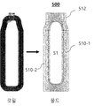
- FIG. 7 is a view showing a plurality of in-coil structures coupled to each other according to the present embodiment.
- FIG. 7 shows a coil structure of a three-phase slotless electric motor, and includes three in-coil structures 500-1 to 500-3.
- the individual en-coil structure 500 includes first coil sides 510-1 and 510-2 facing each other with a first space S1 therebetween.
- At least one end of the first coil sides 510-1 and 510-2 in the longitudinal direction is formed with a first end turn 512 bent in the first direction.
- the individual in-coil structures have a fan-shaped cross section in the width direction. That is, the first coil sides 510-1 and 510-2 and the first end turn 512 have a fan shape in the width direction.
- the first end turn 512 of the in-coil structure has a radius smaller than the first coil sides 510-1 and 510-2 in the concentric direction.
- FIG. 8 is a view showing a plurality of out-coil structures coupled to each other according to the present embodiment.
- the individual out-coil structure includes second coil sides 610-1 and 610-2 facing each other with a second space S2 therebetween.
- At least one end of the second coil sides 610-1 and 610-2 in the longitudinal direction is formed with a second end turn 612 bent in the second direction.
- the second coil sides 610-1 and 610-2 and the second end turn 612 have a fan-shaped cross section in the width direction.
- the second end turn 612 of the out-coil structure has a larger radius than the second coil sides 610-1 and 610-2 in the concentric direction.
- first end turn 512 and the second end turn 612 have a shape curved in opposite directions, and preferably, the first end turn 512 is formed inward of the first coil sides 510. 2
- the end turn 612 has a shape bent outward of the second coil sides 610.
- FIG. 9 is a view showing a combined state of an in-coil structure and an out-coil structure according to the present embodiment
- FIG. 10 is a view showing an upper cross section when the in-coil structure and the out-coil structure are combined
- FIG. 11 is this embodiment It is a view showing a lower cross section when the in-coil structure and the out-coil structure are combined according to an example.
- the plurality of out-coil structures are disposed in a state in which the second coil sides 610 of different out-coil assemblies form a concentric circle in contact with each other, and surround the plurality of in-coil structures.
- At least one of the first coil sides of the in-coil assembly is disposed at a position of the space S2 of the out-coil assembly.
- the sum of the widths of C1 and C2 is equal to the width of the space S2.
- the number of in-coil assemblies and out-coil assemblies may be provided in a different number from that of FIG. 9, and in this case, at least one of the first coil sides of the in-coil assembly is the space of the out-coil assembly (S2 ).
- the first coil sides 510 and the second coil sides 610 in the concentric direction have the same radius, and the outer radius of the first end turn 512 curved inward is It is the same as the inner radius of the first and second coil sides 510 and 610, and the inner radius of the second end turn 612 outwardly is the same as the outer radius of the first and second coil sides 510 and 610.
- the first coil sides 510 of the in-coil structure and the second coil sides 610 of the out-coil structure are formed to have the same radius, so that the effective pore length is the same at any point. Accordingly, the possibility of phase imbalance occurring due to the constant effective air gap length is reduced, and in a slotless motor, the structure is simple and the manufacturability is further improved.
- the second end turns 612 of the outcoil structure according to the present embodiment have symmetric first inclined portions 614 at both ends.
- the notch 900 is formed at a position adjacent to the first inclined portion 614 of the plurality of second end turns 612.
- a third end turn 620 having the same radius as the second coil sides 610 is provided at the other end of the out-coil structure opposite to the second end turn 612, and the third end turn 620
- the second inclined portions 622 may also be formed at both ends.
- a plurality of notches 900 are formed on the upper side and the lower side when the plurality of in-coil structures and the out-coil structures are combined.
- FIG. 12 is a view showing a coupled state of a slotless motor coil assembly and a housing according to an embodiment of the present invention.
- the housing 1200 according to the present embodiment may be provided on at least one of the upper or lower portion of the coil assembly.
- the housing 1200 may include a body 1202 having a circular shape and a plurality of protrusions 1204 coupled to a plurality of notches 900 formed by an outcoil assembly on one surface of the body 1202.
- the in-coil assembly and the out-coil assembly are provided through an injection process, rather than individually winding the coil, and both ends of the second end turn of the out-coil assembly
- a plurality of notches is formed through the inclined portion, and by coupling the plurality of notches and the housing, the coil can be uniformly distributed with respect to the stator without using an adhesive, and can be stably coupled to the stator.
Landscapes
- Engineering & Computer Science (AREA)
- Power Engineering (AREA)
- Manufacturing & Machinery (AREA)
- Windings For Motors And Generators (AREA)
Abstract
본 발명은 슬롯리스 전동기의 코일 조립체, 하우징 및 이를 포함하는 슬롯리스 전동기를 개시한다. 본 발명에 따르면, 제1 공간을 사이에 두고 서로 대향하며 단면이 폭 방향으로 부채꼴 형상을 갖는 두 개의 제1 코일변들을 가지며 상기 두 개의 제1 코일변들의 길이 방향의 적어도 일단에서 제1 방향으로 휘어진 제1 엔드턴을 갖는 복수의 제1 코일 구조체 및 제2 공간을 사이에 두고 서로 대향하며 단면이 폭 방향으로 부채꼴 형상을 갖는 두 개의 제2 코일변들을 가지며 상기 두 개의 제2 코일변들의 길이 방향의 적어도 일단에서 제2 방향으로 휘어진 제2 엔드턴을 갖는 복수의 제2 코일 구조체를 포함하되, 상기 복수의 제1 코일 구조체 및 상기 제2 코일 구조체는 서로 결합하여 원형 고정자 권선 구조를 형성하는 슬롯리스 전동기의 코일 조립체가 제공된다.
Description
본 발명은 슬롯리스 전동기의 코일 조립체, 하우징 및 이를 포함하는 슬롯리스 전동기에 관한 것이다.
일반적인 전동기에서 고정자는 전기자 코일이 감기는 부분인 슬롯과 전기자 코일에서 발생한 자속의 통로 역할을 하도록 철심으로 이루어진 치를 갖는다. 이러한 슬롯 구조는 퍼미언스(permeance)가 최대화되어 높은 공극 자속 밀도를 얻게 해 주지만, 코깅토크의 발생이 불가피하다.
그리고, 코어리스 구조라고도 불리는 슬롯리스 구조는 슬롯이 없는 구조이며, 코깅토크 없이 매우 일정한 토크를 발생시킨다. 따라서, 슬롯리스 구조는 소음 및 진동 측면에서 우수하고 철심의 사용량이 대폭 감소하기 때문에 철손이 적고 기계적 시상수가 작아 제어성이 좋다.
하지만, 이러한 슬롯리스 전동기의 권선은 철심에 감기지 않는 공심 구조로서, 코일 자체의 형태만으로 고정자에 결합되어야 하기 때문에 코어 타입 전동기에 대비하여 제작성이 떨어진다.
도 1 내지 도 3은 종래기술에 따른 슬롯리스 전동기의 권선 구조를 나타낸 도면이다.
도 1은 루프 타일(기와) 방식으로 구성된 슬롯리스 전동기의 권선 구조이다. 즉, 도 1의 권선 구조는 하나의 턴을 구성하는 2개의 코일변의 높이를 다르게 하여 여러 코일이 서로 맞물린 형태가 되도록 중첩시킨 것이다.
그래서, 도 1의 권선 구조는 코일을 고정자의 원주를 따라 이어나갈 때, 공극에 변화가 없으며, 코일과 코일이 서로 맞물리게 되면서 고정이 용이하여 제작 측면에서도 유리하다.
하지만, 도 1의 권선 구조는, 여러 턴의 코일을 만들 때, 양측 코일변의 높이가 차이나도록 제조하는 것이 어렵다는 문제가 있다.
또한, 여러 개의 코일들이 동일한 형상으로 만들어지지 못하면, 코일들이 맞물리게 되어 권선을 이어나가는데 있어서도 제작에 어려움이 있으며, 각 상을 이루는 코일의 형상에 차이가 있으면 상 불평형이 일어날 수 있는 문제가 있다.
그리고, 도 2에 도시된 권선 구조는 여러 코일을 고정자의 원주 방향을 따라 일정한 거리만큼 이격시켜 적층시키며, 코일들이 적층되면서 맞닿게 되어 코일의 두께가 증가하는 부분은 압축시켜 유효 공극 길이를 최소화한 것이다.
하지만, 도 2의 권선 구조는, 코일들을 일정한 간격을 두고 적층하여 제조하는 것이 어렵다는 문제가 있다. 특히, 도 2의 권선 구조는, 코일들이 서로 중첩되는 부분을 압축하여 공극 길이를 최소화하기 위한 것인데, 압축을 하더라도 중첩되지 않은 상태와 비교하여 유효 공극 길이가 늘어나며 제조 기술 수준에 따라 공극이 불균일해질 가능성이 높은 문제가 있다.
그리고, 도 3에 도시된 권선 구조는 코일들이 상호간에 마주 바라보게 배치되며, 수평 폭이 큰 코일의 양측 단부 내측에 수평 폭이 작은 코일의 양측 단부를 중첩시킨 것이다.
하지만, 도 3의 권선 구조도, 코일들이 중첩되는 부분에서 유효 공극 길이가 달라지게 되어, 각 코일의 인덕턴스에 차이가 발생할 수 있는 문제가 있으며, 여러 코일을 일일이 마주보게 하여 고정시키는 과정이 번거로운 문제가 있다.
상기한 종래기술의 문제점을 해결하기 위해, 본 발명은 유효 공극 길이가 어느 지점에서나 동일한 슬롯리스 전동기의 코일 조립체, 하우징 및 이를 포함하는 슬롯리스 전동기를 제안하고자 한다.
상기한 바와 같은 목적을 달성하기 위하여, 본 발명의 일 실시예에 따르면, 슬롯리스 전동기의 코일 조립체에 있어서, 제1 공간을 사이에 두고 서로 대향하며 단면이 폭 방향으로 부채꼴 형상을 갖는 두 개의 제1 코일변들을 가지며 상기 두 개의 제1 코일변들의 길이 방향의 적어도 일단에서 제1 방향으로 휘어진 제1 엔드턴을 갖는 복수의 제1 코일 구조체; 및 제2 공간을 사이에 두고 서로 대향하며 단면이 폭 방향으로 부채꼴 형상을 갖는 두 개의 제2 코일변들을 가지며 상기 두 개의 제2 코일변들의 길이 방향의 적어도 일단에서 제2 방향으로 휘어진 제2 엔드턴을 갖는 복수의 제2 코일 구조체를 포함하되, 상기 복수의 제1 코일 구조체 및 상기 제2 코일 구조체는 서로 결합하여 원형 고정자 권선 구조를 형성하는 슬롯리스 전동기의 코일 조립체가 제공된다.
상기 원형 고정자 권선 구조 형성을 위해 결합 시, 상기 복수의 제1 코일 구조체의 제1 엔드턴들과 상기 복수 제2 코일 구조체의 제2 엔드턴들은 서로 반대 방향에 배치될 수 있다.
상기 원형 고정자 권선 구조 형성을 위해 결합 시, 상기 복수의 제1 코일 구조체는 안쪽에 위치하며, 상기 복수의 제2 코일 구조체는 상기 복수의 제1 코일 구조체의 바깥쪽에 상기 복수의 제1 코일 구조체를 감싸면서 배치될 수 있다.
상기 제1 코일변들 및 상기 제2 코일변들은 동심원 방향으로 동일 반경을 가지며, 상기 제1 엔드턴의 외측 반경은 상기 제1 및 제2 코일변들의 내측 반경과 동일하며, 상기 제2 엔드턴의 내측 반경은 상기 제1 및 제2 코일변들의 외측 반경과 동일하게 형성될 수 있다.
상기 복수의 제2 코일 구조체의 제2 엔드턴은 양단에 대칭 형태의 경사부를 가지며, 상기 원형 고정자 권선 구조 형성을 위해 서로 다른 제2 코일 구조체가 결합하는 경우 상기 대칭 형태의 경사부에 의해 노치가 형성될 수 있다.
상기 원형 고정자 권선 구조 형성 이후, 상기 복수의 제2 코일 조립체 상부 및 하부 중 적어도 하나에 하우징이 결합될 수 있다.
상기 하우징은 상기 복수의 제2 코일 조립체에 의해 형성된 복수의 노치와 결합하는 복수의 돌기부를 가질 수 있다.
상기 복수의 제1 코일 조립체 및 제2 코일 조립체는 코일 몰드 구조일 수 있다.
상기 복수의 제2 코일 구조체의 제2 엔드턴에 대향하는 타단에 상기 제2 코일변들과 동일 반경을 가지는 제3 엔드턴이 제공되고, 상기 제3 엔드턴의 양단에 대칭 형태의 제2 경사부를 가지며, 상기 원형 권선 구조 형성을 위해 서로 다른 제2 코일 구조체가 결합하는 경우 상기 대칭 형태의 제2 경사부에 의해 노치가 형성될 수 있다.
본 발명의 다른 측면에 따르면 상기한 코일 조립체를 포함하는 슬롯리스 전동기.
본 발명의 또 다른 측면에 따르면, 슬롯리스 전동기의 코일 조립체 하우징으로서, 본체; 및 상기 본체의 일면에 형성되는 복수의 돌기부를 포함하되, 상기 복수의 돌기부는, 상기 슬롯리스 전동기의 코일 조립체를 구성하는 복수의 코일 구조체의 결합에 의해 형성된 복수의 노치와 결합하고, 상기 슬롯리스 전동기의 코일 조립체는 제1 공간을 사이에 두고 서로 대향하며 단면이 폭 방향으로 부채꼴 형상을 갖는 두 개의 제1 코일변들을 가지며 상기 두 개의 제1 코일변들의 길이 방향의 적어도 일단에서 제1 방향으로 휘어진 제1 엔드턴을 갖는 복수의 제1 코일 구조체 및 제2 공간을 사이에 두고 서로 대향하며 단면이 폭 방향으로 부채꼴 형상을 갖는 두 개의 제2 코일변들을 가지며 상기 두 개의 제2 코일변들의 길이 방향의 적어도 일단에서 제2 방향으로 휘어진 제2 엔드턴을 갖는 복수의 제2 코일 구조체를 포함하고, 상기 복수의 제1 코일 구조체 및 상기 제2 코일 구조체는 서로 결합하여 원형 고정자 권선 구조를 형성하는 슬롯리스 전동기의 코일 조립체 하우징이 제공될 수 있다.
본 발명에 따르면, 유효 공극 길이가 어느 지점에서나 동일하고, 유효 공극 길이가 늘어나면서 출력이 저하될 우려가 없는 장점이 있다.
또한, 본 발명에 따르면, 상 불평형이 일어날 가능성이 줄어드며, 구조가 매우 간단해지는 동시에 제작에도 유리한 장점이 있다.
도 1 내지 도 3은 종래기술에 따른 슬롯리스 전동기의 권선 구조를 나타낸 도면이다.
도 4는 본 발명의 일 실시예에 따른 슬롯리스 전동기의 코일 조립체의 원형 고정자 권선 내부 형성 과정을 도시한 도면이다.
도 5는 본 실시예에 따른 개별 인코일 구조체의 제조 과정을 도시한 도면이다.
도 6은 본 실시예에 따른 개별 아웃코일 구조체의 제조 과정을 도시한 도면이다.
도 7은 본 실시예에 따른 서로 결합된 복수의 인코일 구조체를 도시한 도면이다.
도 8은 본 실시예에 따른 서로 결합된 복수의 아웃코일 구조체를 도시한 도면이다.
도 9는 본 실시예에 따른 인코일 구조체와 아웃코일 구조체의 결합 상태를 도시한 도면이다.
도 10은 인코일 구조체와 아웃코일 구조체의 결합 시 상측 단면을 도시한 도면이다.
도 11은 본 실시예에 따른 인코일 구조체와 아웃코일 구조체의 결합 시 하측 단면을 도시한 도면이다.
도 12는 본 발명의 바람직한 일 실시예에 따른 슬롯리스 전동기 코일 조립체와 하우징의 결합 상태를 도시한 도면이다.
본 발명은 다양한 변경을 가할 수 있고 여러 가지 실시예를 가질 수 있는 바, 특정 실시예들을 도면에 예시하고 상세하게 설명하고자 한다.
그러나, 이는 본 발명을 특정한 실시 형태에 대해 한정하려는 것이 아니며, 본 발명의 사상 및 기술 범위에 포함되는 모든 변경, 균등물 내지 대체물을 포함하는 것으로 이해되어야 한다.
본 발명은 내부와 외부에 각각 위치하는 공심 권선 구조물을 이용하여 원형의 고정자 권선 내부를 형성할 수 있는 슬롯리스 전동기의 코일 조립체를 제안한다.
도 4는 본 발명의 일 실시예에 따른 슬롯리스 전동기의 코일 조립체의 원형 고정자 권선 내부 형성 과정을 도시한 도면이다.
도 4를 참조하면, 원형 권선 구조 형성 시 안쪽에 위치하는 복수의 인코일 구조체(제1 코일 구조체)를 제조하고(단계 400), 이와 함께 바깥쪽에 위치하는 복수의 아웃코일 구조체(제2 코일 구조체)를 제조한다(단계 402).
이후, 복수의 인코일 구조체를 내부에 배치하고, 복수의 인코일 구조체 외부에 복수의 아웃코일 구조체를 배치하여 원형의 고정자 권선 내부를 형성한다(단계 404).
도 5는 본 실시예에 따른 개별 인코일 구조체의 제조 과정을 도시한 도면이고, 도 6은 본 실시예에 따른 개별 아웃코일 구조체의 제조 과정을 도시한 도면이다.
도 5 내지 도 6을 참조하면, 인코일 구조체 및 아웃코일 구조체는 코일을 감은 후에 사출 공정을 통해 몰드 형태로 제조된다.
이때, 인코일 구조체와 아웃코일 구조체는 서로 결합 가능한 공심 권선 구조물로 형성되며, 이에 대한 구조는 이하에서 상술될 것이다.
도 7은 본 실시예에 따른 서로 결합된 복수의 인코일 구조체를 도시한 도면이다.
도 7은 3상 슬롯리스 전동기의 코일 구조체를 도시한 것으로서, 3개의 인코일 구조체(500-1 내지 500-3)를 포함한다.
도 5 및 도 7을 참조하면, 개별 인코일 구조체(500)는 제1 공간(S1)을 사이에 두고 서로 대향하는 제1 코일변들(510-1,510-2)을 포함한다.
또한, 제1 코일변들(510-1,510-2)의 길이 방향의 적어도 일단에는 제1 방향으로 휘어진 제1 엔드턴(512)이 형성된다.
바람직하게, 개별 인코일 구조체는 단면이 폭 방향으로 부채꼴 형상을 갖는다. 즉, 제1 코일변들(510-1,510-2)과 제1 엔드턴(512)은 폭 방향으로 부채꼴 형상을 가진다.
인코일 구조체의 제1 엔드턴(512)은 동심원 방향으로 제1 코일변들(510-1,510-2)보다 작은 반경을 가지게 된다.
도 8은 본 실시예에 따른 서로 결합된 복수의 아웃코일 구조체를 도시한 도면이다.
도 8은 3상 슬롯리스 전동기에서 3개의 아웃코일 구조체(600-1 내지 600-3)이 제공된 것을 도시한 것이다.
도 6 및 8을 참조하면, 개별 아웃코일 구조체는 제2 공간(S2)을 사이에 두고 서로 대향하는 제2 코일변들(610-1,610-2)을 포함한다.
또한, 제2 코일변들(610-1,610-2)의 길이 방향의 적어도 일단에는 제2 방향으로 휘어진 제2 엔드턴(612)이 형성된다.
바람직하게, 여기서, 제2 코일변들(610-1,610-2)과 제2 엔드턴(612)은 단면이 폭 방향으로 부채꼴 형상을 가진다.
아웃코일 구조체의 제2 엔드턴(612)은 동심원 방향으로 제2 코일변들(610-1,610-2)보다 큰 반경을 가지게 된다.
여기서, 제1 엔드턴(512)과 제2 엔드턴(612)은 서로 반대 방향으로 휘어진 형상을 가지며, 바람직하게, 제1 엔드턴(512)은 제1 코일변들(510)의 안쪽으로 제2 엔드턴(612)은 제2 코일변들(610)의 바깥쪽으로 휘어진 형상을 갖는다.
도 9는 본 실시예에 따른 인코일 구조체와 아웃코일 구조체의 결합 상태를 도시한 도면이고, 도 10은 인코일 구조체와 아웃코일 구조체의 결합 시 상측 단면을 도시한 도면이고, 도 11은 본 실시예에 따른 인코일 구조체와 아웃코일 구조체의 결합 시 하측 단면을 도시한 도면이다.
도 9에 도시된 바와 같이, 원형 권선 구조 형성을 위해, 인코일 조립체 및 아웃코일 조립체가 결합하는 경우, 서로 다른 인코일 조립체의 제1 코일변들(510) 및 제1 엔드턴(512)이 접한 상태로 단면이 동심원을 형성하면서 내부에 배치된다.
복수의 아웃코일 구조체는 서로 다른 아웃코일 조립체의 제2 코일변들(610)이 접한 상태로 단면이 동심원을 형성하고 복수의 인코일 구조체를 감싸면서 배치된다.
도 9를 참조하면, 원형 권선 구조 형성 시, 인코일 조립체의 제1 코일변 중 적어도 하나가 아웃코일 조립체의 공간(S2) 위치에 배치된다.
3상 전동기의 경우, 제1 인코일 조립체의 하나의 제1 코일변(C1)과, 제1 인코일 조립체에 인접 배치되는 제2 인코일 조립체의 적어도 하나의 제1 코일변(C2)이 제1 아웃코일 조립체에 형성된 공간(S2) 내에 배치된다.
바람직하게, C1과 C2의 폭의 합은 공간(S2)의 폭과 동일하다.
3상이 아닌 2상 전동기의 경우, 인코일 조립체와 아웃코일 조립체의 수가 도 9와는 다른 개수로 제공될 수 있고, 이 경우 인코일 조립체의 제1 코일변 중 적어도 하나가 아웃코일 조립체의 공간(S2)내에 위치할 수도 있다.
도 9 내지 도 11을 참조하면, 동심원 방향으로 제1 코일변들(510) 및 제2 코일변들(610)은 동일 반경을 가지며, 안쪽으로 휘어진 제1 엔드턴(512)의 외측 반경은 제1 및 제2 코일변들(510,610)의 내측 반경과 동일하며, 바깥쪽으로 제2 엔드턴(612)의 내측 반경은 제1 및 제2 코일변들(510,610)의 외측 반경과 동일하게 형성된다.
상기한 구조를 통해 인코일 구조체의 제1 코일변들(510)와 아웃코일 구조체의 제2 코일변들(610)들이 동일한 반경을 가지면서 형성되어 유효 공극 길이가 어느 지점에서나 동일해진다. 이에 따라 유효 공극 길이가 일정하여 상 불평형이 발생할 가능성이 줄어들고, 슬롯리스 전동기에서 구조가 간단하면서도 제작성이 한층 개선된다.
한편, 도 6 및 도 9에 도시된 바와 같이, 본 실시예에 따른 아웃코일 구조체의 제2 엔드턴(612)은 양단에 대칭 형태의 제1 경사부(614)를 가진다.
이처럼 대칭 형태의 제1 경사부(614)에 의해 서로 다른 아웃코일 구조체의 결합 시 복수의 제2 엔드턴(612)의 제1 경사부(614)의 인접 위치에 노치(900)가 형성된다.
또한, 아웃코일 구조체의 제2 엔드턴(612)에 대향하는 타단에는 제2 코일변들(610)과 동일 반경을 가지는 제3 엔드턴(620)이 제공되고, 제3 엔드턴(620)의 양단에도 제2 경사부(622)가 형성될 수 있다.
이에 따라 복수의 인코일 구조체 및 아웃코일 구조체의 결합 시 상측과 하측에 복수의 노치(900)가 형성된다.
도 12는 본 발명의 바람직한 일 실시예에 따른 슬롯리스 전동기 코일 조립체와 하우징의 결합 상태를 도시한 도면이다.
도 12에 도시된 바와 같이, 본 실시예에 따른 하우징(1200)은 코일 조립체의 상부 또는 하부 중 적어도 하나에 제공될 수 있다.
하우징(1200)은 원 형상의 본체(1202) 및 본체(1202)의 일면에 아웃코일 조립체에 의해 형성된 복수의 노치(900)와 결합하는 복수의 돌기부(1204)를 포함할 수 있다.
본 실시예에서와 같이, 슬롯리스 전동기에서 공심 권선 구조를 형성함에 있어 개별적으로 코일을 감는 것이 아니라, 사출 공정으로 인코일 조립체와 아웃코일 조립체를 제공하고, 아웃코일 조립체의 제2 엔드턴 양단의 경사부를 통해 복수의 노치를 형성하며, 복수의 노치와 하우징을 결합함으로써 접착제를 사용하지 않고도 코일을 고정자에 대해 균일하게 분포시킬 수 있고 또한 고정자에 안정적으로 결합시킬 수 있다.
상기한 본 발명의 실시예는 예시의 목적을 위해 개시된 것이고, 본 발명에 대한 통상의 지식을 가지는 당업자라면 본 발명의 사상과 범위 안에서 다양한 수정, 변경, 부가가 가능할 것이며, 이러한 수정, 변경 및 부가는 하기의 특허청구범위에 속하는 것으로 보아야 할 것이다.
Claims (11)
- 슬롯리스 전동기의 코일 조립체에 있어서,제1 공간을 사이에 두고 서로 대향하며 단면이 폭 방향으로 부채꼴 형상을 갖는 두 개의 제1 코일변들을 가지며 상기 두 개의 제1 코일변들의 길이 방향의 적어도 일단에서 제1 방향으로 휘어진 제1 엔드턴을 갖는 복수의 제1 코일 구조체; 및제2 공간을 사이에 두고 서로 대향하며 단면이 폭 방향으로 부채꼴 형상을 갖는 두 개의 제2 코일변들을 가지며 상기 두 개의 제2 코일변들의 길이 방향의 적어도 일단에서 제2 방향으로 휘어진 제2 엔드턴을 갖는 복수의 제2 코일 구조체를 포함하되,상기 복수의 제1 코일 구조체 및 상기 제2 코일 구조체는 서로 결합하여 원형 고정자 권선 구조를 형성하는 슬롯리스 전동기의 코일 조립체.
- 제1항에 있어서,상기 원형 고정자 권선 구조 형성을 위해 결합 시, 상기 복수의 제1 코일 구조체의 제1 엔드턴들과 상기 복수 제2 코일 구조체의 제2 엔드턴들은 서로 반대 방향에 배치되는 슬롯리스 전동기의 코일 조립체.
- 제1항에 있어서,상기 원형 고정자 권선 구조 형성을 위해 결합 시, 상기 복수의 제1 코일 구조체는 안쪽에 위치하며, 상기 복수의 제2 코일 구조체는 상기 복수의 제1 코일 구조체의 바깥쪽에 상기 복수의 제1 코일 구조체를 감싸면서 배치되는 슬롯리스 전동기의 코일 조립체.
- 제1항에 있어서,상기 제1 코일변들 및 상기 제2 코일변들은 동심원 방향으로 동일 반경을 가지며, 상기 제1 엔드턴의 외측 반경은 상기 제1 및 제2 코일변들의 내측 반경과 동일하며, 상기 제2 엔드턴의 내측 반경은 상기 제1 및 제2 코일변들의 외측 반경과 동일하게 형성되는 슬롯리스 전동기의 코일 조립체.
- 제1항에 있어서,상기 복수의 제2 코일 구조체의 제2 엔드턴은 양단에 대칭 형태의 경사부를 가지며, 상기 원형 고정자 권선 구조 형성을 위해 서로 다른 제2 코일 구조체가 결합하는 경우 상기 대칭 형태의 경사부에 의해 노치가 형성되는 슬롯리스 전동기의 코일 조립체.
- 제5항에 있어서,상기 원형 고정자 권선 구조 형성 이후, 상기 복수의 제2 코일 조립체 상부 및 하부 중 적어도 하나에 하우징이 결합되는 슬롯리스 전동기의 코일 조립체.
- 제6항에 있어서,상기 하우징은 상기 복수의 제2 코일 조립체에 의해 형성된 복수의 노치와 결합하는 복수의 돌기부를 갖는 슬롯리스 전동기의 코일 조립체.
- 제1항에 있어서,상기 복수의 제1 코일 조립체 및 제2 코일 조립체는 코일 몰드 구조인 슬롯리스 전동기의 코일 조립체.
- 제5항에 있어서,상기 복수의 제2 코일 구조체의 제2 엔드턴에 대향하는 타단에 상기 제2 코일변들과 동일 반경을 가지는 제3 엔드턴이 제공되고, 상기 제3 엔드턴의 양단에 대칭 형태의 제2 경사부를 가지며, 상기 원형 권선 구조 형성을 위해 서로 다른 제2 코일 구조체가 결합하는 경우 상기 대칭 형태의 제2 경사부에 의해 노치가 형성되는 슬롯리스 전동기의 코일 조립체.
- 제1항에 따른 코일 조립체를 포함하는 슬롯리스 전동기.
- 슬롯리스 전동기의 코일 조립체 하우징으로서,본체; 및상기 본체의 일면에 형성되는 복수의 돌기부를 포함하되,상기 복수의 돌기부는, 상기 슬롯리스 전동기의 코일 조립체를 구성하는 복수의 코일 구조체의 결합에 의해 형성된 복수의 노치와 결합하고,상기 슬롯리스 전동기의 코일 조립체는 제1 공간을 사이에 두고 서로 대향하며 단면이 폭 방향으로 부채꼴 형상을 갖는 두 개의 제1 코일변들을 가지며 상기 두 개의 제1 코일변들의 길이 방향의 적어도 일단에서 제1 방향으로 휘어진 제1 엔드턴을 갖는 복수의 제1 코일 구조체 및 제2 공간을 사이에 두고 서로 대향하며 단면이 폭 방향으로 부채꼴 형상을 갖는 두 개의 제2 코일변들을 가지며 상기 두 개의 제2 코일변들의 길이 방향의 적어도 일단에서 제2 방향으로 휘어진 제2 엔드턴을 갖는 복수의 제2 코일 구조체를 포함하고, 상기 복수의 제1 코일 구조체 및 상기 제2 코일 구조체는 서로 결합하여 원형 고정자 권선 구조를 형성하는 슬롯리스 전동기의 코일 조립체 하우징.
Priority Applications (1)
| Application Number | Priority Date | Filing Date | Title |
|---|---|---|---|
| US17/438,087 US12068652B2 (en) | 2019-03-12 | 2020-02-19 | Coil assembly of slotless motor, housing and slotless motor including the same |
Applications Claiming Priority (2)
| Application Number | Priority Date | Filing Date | Title |
|---|---|---|---|
| KR10-2019-0027880 | 2019-03-12 | ||
| KR1020190027880A KR102233003B1 (ko) | 2019-03-12 | 2019-03-12 | 슬롯리스 전동기의 코일 조립체, 하우징 및 이를 포함하는 슬롯리스 전동기 |
Publications (2)
| Publication Number | Publication Date |
|---|---|
| WO2020184860A2 true WO2020184860A2 (ko) | 2020-09-17 |
| WO2020184860A3 WO2020184860A3 (ko) | 2020-12-10 |
Family
ID=72427506
Family Applications (1)
| Application Number | Title | Priority Date | Filing Date |
|---|---|---|---|
| PCT/KR2020/002396 Ceased WO2020184860A2 (ko) | 2019-03-12 | 2020-02-19 | 슬롯리스 전동기의 코일 조립체, 하우징 및 이를 포함하는 슬롯리스 전동기 |
Country Status (3)
| Country | Link |
|---|---|
| US (1) | US12068652B2 (ko) |
| KR (1) | KR102233003B1 (ko) |
| WO (1) | WO2020184860A2 (ko) |
Families Citing this family (4)
| Publication number | Priority date | Publication date | Assignee | Title |
|---|---|---|---|---|
| US11677303B2 (en) * | 2021-10-21 | 2023-06-13 | National Cheng Kung University | Motor and coreless stator coil winding unit thereof |
| KR102693855B1 (ko) * | 2022-11-22 | 2024-08-12 | 가천대학교 산학협력단 | 축 방향 자속 영구자석 전동기 |
| KR102717767B1 (ko) * | 2023-06-22 | 2024-10-16 | 한국전력공사 | 슬롯리스 권선배치를 위한 블록코일의 제조방법 및 그에 따른 조립체 |
| KR102903182B1 (ko) * | 2024-11-19 | 2025-12-30 | 한양대학교 산학협력단 | 내전형과 외전형 전동기 공용이 가능한 고정자 및 이를 포함하는 슬롯리스 전동기. |
Family Cites Families (12)
| Publication number | Priority date | Publication date | Assignee | Title |
|---|---|---|---|---|
| US3079519A (en) * | 1956-02-29 | 1963-02-26 | Gen Electric | Coil and method of insulating same |
| US6894418B2 (en) * | 2002-07-30 | 2005-05-17 | Comprehensive Power, Inc. | Nested stator coils for permanent magnet machines |
| US7619345B2 (en) * | 2006-01-30 | 2009-11-17 | American Superconductor Corporation | Stator coil assembly |
| DE102009032883A1 (de) * | 2009-07-13 | 2011-01-27 | Siemens Aktiengesellschaft | Wickelkopfanordnung |
| DE112011100868T5 (de) * | 2010-03-11 | 2012-12-27 | Kabushiki Kaisha Toyota Jidoshokki | Stator für eine rotierende elektrische Maschine, Herstellungsverfahren eines Stators und Herstellungsverfahren einer Wicklung für einen Stator |
| JP2014068460A (ja) * | 2012-09-26 | 2014-04-17 | Seiko Epson Corp | 電気機械装置および電気機械装置に用いられるローター、並びに、電気機械装置を用いた移動体およびロボット |
| KR101510317B1 (ko) | 2013-11-29 | 2015-04-14 | 한국정보통신주식회사 | 카드 리더기 |
| JP6424078B2 (ja) * | 2014-02-13 | 2018-11-14 | 山洋電気株式会社 | ステータ、ステータの製造方法、およびモータ |
| JP6581848B2 (ja) * | 2015-08-31 | 2019-09-25 | 有限会社Uno | コアレスモータ用コイルの製造方法 |
| JP6811042B2 (ja) * | 2016-07-12 | 2021-01-13 | 日本電産コパル電子株式会社 | コアレスコイル及びこのコアレスコイルの製造方法 |
| KR101769717B1 (ko) * | 2016-09-19 | 2017-08-21 | 한양대학교 산학협력단 | 슬롯리스 전동기 및 이의 코일부 |
| KR101892961B1 (ko) * | 2016-11-29 | 2018-08-29 | 엘지전자 주식회사 | 코어리스모터 |
-
2019
- 2019-03-12 KR KR1020190027880A patent/KR102233003B1/ko active Active
-
2020
- 2020-02-19 US US17/438,087 patent/US12068652B2/en active Active
- 2020-02-19 WO PCT/KR2020/002396 patent/WO2020184860A2/ko not_active Ceased
Also Published As
| Publication number | Publication date |
|---|---|
| KR102233003B1 (ko) | 2021-03-26 |
| WO2020184860A3 (ko) | 2020-12-10 |
| KR20200108985A (ko) | 2020-09-22 |
| US20220190665A1 (en) | 2022-06-16 |
| US12068652B2 (en) | 2024-08-20 |
Similar Documents
| Publication | Publication Date | Title |
|---|---|---|
| WO2020184860A2 (ko) | 슬롯리스 전동기의 코일 조립체, 하우징 및 이를 포함하는 슬롯리스 전동기 | |
| WO2018052268A1 (ko) | 슬롯리스 전동기 및 이의 코일부 | |
| WO2016060311A1 (ko) | 평판형 모터의 고정자 및 이를 이용한 평판형 모터 | |
| US8610328B2 (en) | Rotary electric machine | |
| WO2011136475A2 (ko) | 이중돌극형 영구자석 전기기기의 권선 배치법 | |
| WO2011062373A2 (en) | Winding frame with magmate and stator core with the same | |
| WO2014129791A1 (ko) | 전동기 및 전동기 제조방법 | |
| WO2016036066A1 (ko) | 레졸버의 절연커버 및 레졸버의 절연커버의 코일 권선방법 | |
| WO2019168360A1 (ko) | 점적률 극대화를 위한 3차원 형상을 가지는 평각형 코일 및 이를 포함하는 전동기 | |
| WO2018044038A1 (ko) | 라인기동식 동기형 릴럭턴스 전동기 및 그 회전자 | |
| WO2019045341A1 (ko) | 다수의 코일 고정체를 가지는 개량된 다단형 고전압 발전기 | |
| WO2020197138A1 (ko) | 모터 | |
| WO2017069488A1 (ko) | 로터 코어, 로터 및 이를 포함하는 모터 | |
| WO2021194239A1 (ko) | 비틀린 형상의 평각형 코일 및 이를 위한 스테이터, 그리고 이를 포함하는 전동기 | |
| WO2019009478A1 (ko) | 단순한 버스바 구조를 갖는 브러쉬리스 모터의 결선방법 | |
| WO2014010978A1 (ko) | 전기자유닛 및 이를 구비한 회전기 | |
| WO2017007176A1 (ko) | 이차전지 및 그의 제조방법 | |
| US12506370B2 (en) | Motor formed with a distributed winding coil | |
| WO2015002453A1 (ko) | 분할 코어형 스테이터를 갖는 모터 및 그의 제조 방법 | |
| WO2019027197A1 (ko) | 단일 코일 고정체를 가지는 개량된 고전압 발전기 | |
| WO2024205348A1 (ko) | 토로이달 모터 | |
| WO2021071315A1 (ko) | 모터 | |
| WO2016108614A1 (ko) | 전동기의 회전자 | |
| WO2023008734A1 (ko) | 토로이달 모터 | |
| WO2010032957A2 (ko) | 전력 품질 개선 장치 및 전력 공급 시스템 |
Legal Events
| Date | Code | Title | Description |
|---|---|---|---|
| 121 | Ep: the epo has been informed by wipo that ep was designated in this application |
Ref document number: 20769521 Country of ref document: EP Kind code of ref document: A2 |
|
| NENP | Non-entry into the national phase |
Ref country code: DE |
|
| 122 | Ep: pct application non-entry in european phase |
Ref document number: 20769521 Country of ref document: EP Kind code of ref document: A2 |