WO2020184448A1 - 流量測定装置 - Google Patents
流量測定装置 Download PDFInfo
- Publication number
- WO2020184448A1 WO2020184448A1 PCT/JP2020/009751 JP2020009751W WO2020184448A1 WO 2020184448 A1 WO2020184448 A1 WO 2020184448A1 JP 2020009751 W JP2020009751 W JP 2020009751W WO 2020184448 A1 WO2020184448 A1 WO 2020184448A1
- Authority
- WO
- WIPO (PCT)
- Prior art keywords
- flow rate
- sensor
- temperature
- measuring device
- fluid
- Prior art date
- Legal status (The legal status is an assumption and is not a legal conclusion. Google has not performed a legal analysis and makes no representation as to the accuracy of the status listed.)
- Ceased
Links
Images





Classifications
-
- G—PHYSICS
- G01—MEASURING; TESTING
- G01F—MEASURING VOLUME, VOLUME FLOW, MASS FLOW OR LIQUID LEVEL; METERING BY VOLUME
- G01F1/00—Measuring the volume flow or mass flow of fluid or fluent solid material wherein the fluid passes through a meter in a continuous flow
- G01F1/68—Measuring the volume flow or mass flow of fluid or fluent solid material wherein the fluid passes through a meter in a continuous flow by using thermal effects
- G01F1/684—Structural arrangements; Mounting of elements, e.g. in relation to fluid flow
- G01F1/6847—Structural arrangements; Mounting of elements, e.g. in relation to fluid flow where sensing or heating elements are not disturbing the fluid flow, e.g. elements mounted outside the flow duct
-
- G—PHYSICS
- G01—MEASURING; TESTING
- G01F—MEASURING VOLUME, VOLUME FLOW, MASS FLOW OR LIQUID LEVEL; METERING BY VOLUME
- G01F1/00—Measuring the volume flow or mass flow of fluid or fluent solid material wherein the fluid passes through a meter in a continuous flow
- G01F1/68—Measuring the volume flow or mass flow of fluid or fluent solid material wherein the fluid passes through a meter in a continuous flow by using thermal effects
-
- G—PHYSICS
- G01—MEASURING; TESTING
- G01F—MEASURING VOLUME, VOLUME FLOW, MASS FLOW OR LIQUID LEVEL; METERING BY VOLUME
- G01F1/00—Measuring the volume flow or mass flow of fluid or fluent solid material wherein the fluid passes through a meter in a continuous flow
- G01F1/68—Measuring the volume flow or mass flow of fluid or fluent solid material wherein the fluid passes through a meter in a continuous flow by using thermal effects
- G01F1/684—Structural arrangements; Mounting of elements, e.g. in relation to fluid flow
-
- G—PHYSICS
- G01—MEASURING; TESTING
- G01F—MEASURING VOLUME, VOLUME FLOW, MASS FLOW OR LIQUID LEVEL; METERING BY VOLUME
- G01F1/00—Measuring the volume flow or mass flow of fluid or fluent solid material wherein the fluid passes through a meter in a continuous flow
- G01F1/68—Measuring the volume flow or mass flow of fluid or fluent solid material wherein the fluid passes through a meter in a continuous flow by using thermal effects
- G01F1/684—Structural arrangements; Mounting of elements, e.g. in relation to fluid flow
- G01F1/6842—Structural arrangements; Mounting of elements, e.g. in relation to fluid flow with means for influencing the fluid flow
-
- G—PHYSICS
- G01—MEASURING; TESTING
- G01F—MEASURING VOLUME, VOLUME FLOW, MASS FLOW OR LIQUID LEVEL; METERING BY VOLUME
- G01F1/00—Measuring the volume flow or mass flow of fluid or fluent solid material wherein the fluid passes through a meter in a continuous flow
- G01F1/68—Measuring the volume flow or mass flow of fluid or fluent solid material wherein the fluid passes through a meter in a continuous flow by using thermal effects
- G01F1/684—Structural arrangements; Mounting of elements, e.g. in relation to fluid flow
- G01F1/6845—Micromachined devices
-
- G—PHYSICS
- G01—MEASURING; TESTING
- G01F—MEASURING VOLUME, VOLUME FLOW, MASS FLOW OR LIQUID LEVEL; METERING BY VOLUME
- G01F1/00—Measuring the volume flow or mass flow of fluid or fluent solid material wherein the fluid passes through a meter in a continuous flow
- G01F1/68—Measuring the volume flow or mass flow of fluid or fluent solid material wherein the fluid passes through a meter in a continuous flow by using thermal effects
- G01F1/684—Structural arrangements; Mounting of elements, e.g. in relation to fluid flow
- G01F1/688—Structural arrangements; Mounting of elements, e.g. in relation to fluid flow using a particular type of heating, cooling or sensing element
-
- G—PHYSICS
- G01—MEASURING; TESTING
- G01F—MEASURING VOLUME, VOLUME FLOW, MASS FLOW OR LIQUID LEVEL; METERING BY VOLUME
- G01F1/00—Measuring the volume flow or mass flow of fluid or fluent solid material wherein the fluid passes through a meter in a continuous flow
- G01F1/68—Measuring the volume flow or mass flow of fluid or fluent solid material wherein the fluid passes through a meter in a continuous flow by using thermal effects
- G01F1/684—Structural arrangements; Mounting of elements, e.g. in relation to fluid flow
- G01F1/688—Structural arrangements; Mounting of elements, e.g. in relation to fluid flow using a particular type of heating, cooling or sensing element
- G01F1/6888—Thermoelectric elements, e.g. thermocouples, thermopiles
-
- G—PHYSICS
- G01—MEASURING; TESTING
- G01F—MEASURING VOLUME, VOLUME FLOW, MASS FLOW OR LIQUID LEVEL; METERING BY VOLUME
- G01F1/00—Measuring the volume flow or mass flow of fluid or fluent solid material wherein the fluid passes through a meter in a continuous flow
- G01F1/68—Measuring the volume flow or mass flow of fluid or fluent solid material wherein the fluid passes through a meter in a continuous flow by using thermal effects
- G01F1/696—Circuits therefor, e.g. constant-current flow meters
-
- G—PHYSICS
- G01—MEASURING; TESTING
- G01F—MEASURING VOLUME, VOLUME FLOW, MASS FLOW OR LIQUID LEVEL; METERING BY VOLUME
- G01F1/00—Measuring the volume flow or mass flow of fluid or fluent solid material wherein the fluid passes through a meter in a continuous flow
- G01F1/68—Measuring the volume flow or mass flow of fluid or fluent solid material wherein the fluid passes through a meter in a continuous flow by using thermal effects
- G01F1/696—Circuits therefor, e.g. constant-current flow meters
- G01F1/6965—Circuits therefor, e.g. constant-current flow meters comprising means to store calibration data for flow signal calculation or correction
-
- G—PHYSICS
- G01—MEASURING; TESTING
- G01N—INVESTIGATING OR ANALYSING MATERIALS BY DETERMINING THEIR CHEMICAL OR PHYSICAL PROPERTIES
- G01N25/00—Investigating or analyzing materials by the use of thermal means
- G01N25/56—Investigating or analyzing materials by the use of thermal means by investigating moisture content
-
- G—PHYSICS
- G01—MEASURING; TESTING
- G01N—INVESTIGATING OR ANALYSING MATERIALS BY DETERMINING THEIR CHEMICAL OR PHYSICAL PROPERTIES
- G01N27/00—Investigating or analysing materials by the use of electric, electrochemical, or magnetic means
- G01N27/02—Investigating or analysing materials by the use of electric, electrochemical, or magnetic means by investigating impedance
- G01N27/04—Investigating or analysing materials by the use of electric, electrochemical, or magnetic means by investigating impedance by investigating resistance
-
- G—PHYSICS
- G01—MEASURING; TESTING
- G01N—INVESTIGATING OR ANALYSING MATERIALS BY DETERMINING THEIR CHEMICAL OR PHYSICAL PROPERTIES
- G01N27/00—Investigating or analysing materials by the use of electric, electrochemical, or magnetic means
- G01N27/02—Investigating or analysing materials by the use of electric, electrochemical, or magnetic means by investigating impedance
- G01N27/04—Investigating or analysing materials by the use of electric, electrochemical, or magnetic means by investigating impedance by investigating resistance
- G01N27/14—Investigating or analysing materials by the use of electric, electrochemical, or magnetic means by investigating impedance by investigating resistance of an electrically-heated body in dependence upon change of temperature
- G01N27/18—Investigating or analysing materials by the use of electric, electrochemical, or magnetic means by investigating impedance by investigating resistance of an electrically-heated body in dependence upon change of temperature caused by changes in the thermal conductivity of a surrounding material to be tested
Definitions
- the present invention relates to a flow rate measuring device.
- a flow rate measuring device (see, for example, Patent Documents 1 and 2) that measures the flow rate of a fluid flowing in a path by using a thermal flow sensor provided with a heater and two temperature measuring sensors is known. Further, as such a flow rate measuring device, a device provided with a dew condensation sensor composed of two electrode patterns arranged at a predetermined interval in order to detect the occurrence of dew condensation (see, for example, Patent Document 3) is also known. Has been done.
- the occurrence of dew condensation can be detected.
- the only dew that can be detected by the dew sensor is dew that is larger than the distance between the two electrode patterns that make up the dew sensor. Then, when the humidity becomes high (humidity becomes 100%), the first thing that occurs is minute dew condensation that cannot be detected by the dew condensation sensor.
- the present invention has been made in view of the above situation, and an object of the present invention is to provide a flow rate measuring device capable of detecting high humidity.
- the flow rate measuring device includes a first sensor that measures a value that correlates with the flow rate of the fluid to be measured, two temperature measuring units, and a heating unit arranged in the center of the two temperature measuring units.
- the second sensor is provided with the above, and is arranged at a position where the fluid to be measured flows in the second predetermined direction, in a posture in which the arrangement direction of the two temperature measuring portions and the heating portion is orthogonal to the second predetermined direction.
- the second sensor, the flow rate calculation process for calculating the flow rate of the fluid to be measured based on the value measured by the first sensor, and the temperature of the heating unit of the second sensor are raised to obtain the second sensor.
- the temperature measurement results of the two temperature measuring units are acquired, and it is determined whether or not the humidity of the measurement target fluid is equal to or higher than the predetermined humidity based on whether or not each of the acquired temperature measurement results is equal to or less than a predetermined threshold value. It includes a control unit configured to be able to execute the determination process.
- the flow rate measuring device includes a second sensor arranged so that the temperature measurement result by each temperature measuring unit is not affected by the flow rate (flow velocity) of the fluid to be measured. Then, if the temperature of the heating unit of the second sensor is raised to acquire the temperature measurement results of the two temperature measurement units of the second sensor and each of the acquired temperature measurement results is compared with the threshold value, the humidity of the fluid to be measured is measured. It has been confirmed from various experiments that it is possible to determine whether or not the humidity corresponds to the threshold value. Therefore, according to the flow rate measuring device, it is possible to detect that the humidity has become high (humidity according to a predetermined threshold value).
- the second sensor of the flow rate measuring device may be a sensor used only for determining whether or not the humidity is equal to or higher than a predetermined humidity. Further, the temperature measurement result by one of the two temperature measuring units obtained by raising the temperature of the heating unit to the first temperature and the temperature of the heating unit are set to the first temperature by the control unit. It is possible to execute the correction coefficient calculation process for calculating the correction coefficient used when calculating the flow rate in the flow rate calculation process from the temperature measurement result obtained by the one temperature measuring unit obtained by raising the temperature to a second temperature different from the above. By configuring it, the second sensor may also be used for calculating the correction coefficient.
- a dew condensation sensor composed of two electrode patterns arranged side by side at a predetermined interval is added to the flow rate measuring device, and the control unit determines whether or not dew condensation has occurred based on the resistance value of the dew condensation sensor. 2
- the determination process may be configured to be executable.
- Each temperature measuring part of the second sensor may be a resistance temperature sensor or a thermocouple, but if each temperature measuring part is set as a thermopile having a large output voltage, a flow measuring device that is not easily affected by noise can be obtained. Can be done. Further, if sensors having the same configuration are used as the first sensor and the second sensor, the manufacturing cost of the flow rate measuring device can be reduced as compared with the case where the first sensor and the second sensor have different configurations. It can be reduced.
- FIG. 1 is an exploded perspective view of the flow rate measuring device 1 according to the embodiment of the present invention.
- FIG. 2 is a cross-sectional view of the flow rate measuring device.
- FIG. 3 is a plain view of the sub-flow path portion included in the flow rate measuring device.
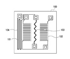
- FIG. 4 is a plan view of a sensor used as a flow rate detection sensor and a physical property value detection sensor.
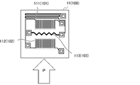
- FIG. 5A is an explanatory diagram of the flow rate detection sensor.
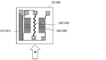
- FIG. 5B is an explanatory diagram of the sensor for detecting the physical property value.
- 6A and 6B are views for explaining the flow rate measurement principle in the flow rate measuring device, in which FIG. 6A shows a temperature distribution in the vicinity of a flow rate detection sensor in a state where gas is not flowing, and FIG.
- FIG. 6B is a diagram in which gas is flowing. The temperature distribution near the flow rate detection sensor in the present state is shown.
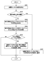
- FIG. 7 is a flow chart of a state detection process executed by the control unit of the flow rate measuring device.
- FIG. 8 is an explanatory diagram of a connection form between the control unit and each sensor on the circuit board of the flow rate measuring device.
- FIG. 9 is an explanatory diagram of the results of an experiment conducted to develop a flow rate measuring device.
- FIG. 1 shows an exploded perspective view of the flow rate measuring device 1 according to the embodiment of the present invention
- FIG. 2 shows a cross-sectional view of the flow rate measuring device 1.
- the flow rate measuring device 1 is a device used by being incorporated in a device (gas meter, fuel cell, etc.) that requires monitoring and adjustment of the fluid flow rate. As shown in FIG. 1, the flow rate measuring device 1 includes a main flow path portion 2, a sub flow path portion 3, a seal 4, a circuit board 5, and a cover 6.
- the main flow path portion 2 is a tubular member through which a fluid whose flow rate should be measured (hereinafter referred to as a measurement target fluid) flows.
- a measurement target fluid a fluid whose flow rate should be measured
- an inflow port 34A is provided on the inner peripheral surface of the main flow path portion 2 on the upstream side in the flow direction of the fluid to be measured.
- an outflow port 35A is provided on the downstream side of the inner peripheral surface of the main flow path portion 2 in the flow direction of the fluid to be measured.
- an orifice 21 for adjusting the amount of fluid flowing through the sub-flow path portion 3 (details will be described later) is provided between the inflow port 34A and the outflow port 35A of the main flow path portion 2.
- the circuit board 5 (FIG. 1) is a unit (printed circuit board) in which a flow rate detection sensor 11, a physical property value detection sensor 12, a control unit 13, and a dew condensation sensor 14 (see FIG. 3) are attached to a printed wiring board.
- the flow rate detection sensor 11, the physical property value detection sensor 12, and the dew condensation sensor 14 are provided on the surface of the circuit board 5 (the surface facing the sub-flow path portion 3; the lower surface in FIG. 1).
- the control unit 13 is provided on the back surface of the circuit board 5. Details of the sensors 11, 12 and 14 and the control unit 13 will be described later.
- the sub-flow path portion 3 (FIGS. 1 and 2) is a bypass flow path for the fluid to be measured, which is provided for measuring the flow rate and the like.
- the sub-flow path portion 3 is sealed by fixing the circuit board 5 with the seal 4 sandwiched between them.
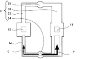
- FIG. 3 shows a plan view of the subchannel portion 3.
- the positions of the sensors 11, 12 and 14 in a state where the circuit board 5 is fixed to the subchannel portion 3 are also shown by a dotted line frame.
- the sub-flow path portion 3 includes an inflow flow path 34 leading to the inflow port 34A and an outflow flow path 35 leading to the outflow port 35A, both of which are for inflow. It is provided with a physical property value detection flow path 32 and a flow rate detection flow path 33, which are flow paths connecting the flow path 34 and the outflow flow path 35. As shown in FIG. 3, the shape of each flow path of the sub-flow path portion 3, the position of each sensor of the circuit board 5, etc.
- the detection sensor 11 is in contact with the fluid flowing through the flow rate detection flow path 33
- the physical property value detection sensor 12 is in contact with the fluid flowing through the physical property value detection flow path 32
- the dew condensation sensor 14 is in contact with the physical property value detection flow path 32 and the flow rate. It is defined to be in contact with the fluid flowing through the detection flow path 33.
- the physical property value detection flow path 32 has a smaller cross-sectional area than the flow rate detection flow path 33. Therefore, as schematically indicated by the sizes of the arrows P and Q, the amount of fluid flowing through the physical property value detection flow path 32 is smaller than the amount of fluid flowing through the flow rate detection flow path 33. There is. The reason why the amount of fluid flowing through the flow rate detection flow path 33 is reduced will be described later.
- the cover 6 (FIG. 1) is a member for protecting the circuit board 5 fixed to the subchannel portion 3.
- the dew condensation sensor 14 is a sensor composed of two electrode patterns (comb-shaped electrode patterns in the present embodiment) formed so that the distance between the parts is a predetermined distance.
- the flow rate detection sensor 11 and the physical property value detection sensor 12 are both sensors 100 having the configuration shown in FIG.
- the sensor 100 is a so-called MEMS flow sensor in which an insulating film including a microheater 103 and thermopile 101 and 102 symmetrically provided with the microheater 103 interposed therebetween is formed on a silicon base.
- the insulating film of the sensor 100 is also provided with a temperature sensor 104 for measuring the reference temperature.
- a cavity is provided in order to reduce the heat capacity of the opposite portion of the insulating film (the portion where the microheater 103 is provided, etc.). (See FIG. 6).
- the flow rate detection sensor 11 and the physical property value detection sensor 12 are sensors 100 having the same configuration.
- the sensor 100 used as the flow rate detection sensor 11 can form the state shown in FIG. 5A, that is, the state in which the fluid to be measured (arrow P) flows in the direction orthogonal to the length direction of the microheater 103. It is attached to the circuit board 5 in a posture.
- the sensor 100 used as the sensor 12 for detecting the physical property value is a circuit in a posture shown in FIG. 5B, that is, a state in which the fluid to be measured (arrow Q) flows in the length direction of the microheater 103. It is attached to the substrate 5.
- thermopile 101 the thermopile 102, and the microheater 103 of the sensor 100 used as the flow rate detection sensor 11 are referred to as a thermopile 111, a thermopile 112, and a microheater 113, respectively, as shown in FIG. 5A.
- thermopile 101, the thermopile 102, and the microheater 103 of the sensor 100 used as the sensor 12 for detecting the physical property value are described as the thermopile 121, the thermopile 122, and the microheater 123, respectively. write.
- the control unit 13 is a unit (ASIC in this embodiment) that executes a flow rate calculation process, a sensitivity correction coefficient calculation process, and a state detection process, and is provided with a communication interface circuit for communicating with an external device.
- the control unit 13 according to the present embodiment periodically performs each process, but the control unit 13 executes each process when an execution instruction for each process is given from an external device. Is also good.
- ⁇ Flow rate calculation process In the flow rate calculation process, the temperature of the microheater 113 of the flow rate detection sensor 11 is raised, and the difference ⁇ V (hereinafter, referred to as sensor output value ⁇ V) between the output voltages of the thermopile 111 and 112 of the flow rate detection sensor 11 is measured. This is a process of calculating the flow rate of the fluid to be measured based on the measured sensor output value ⁇ V.
- the temperature of the microheater 113 of the flow rate detection sensor 11 when the temperature of the microheater 113 of the flow rate detection sensor 11 is raised in a state where the gas is not flowing, the temperature distribution of the gas is on the upstream side of the microheater 113 as shown in FIG. 6A. It becomes a target on the downstream side.
- the temperature of the microheater 113 if the temperature of the microheater 113 is raised while the gas is flowing, the temperature of the gas on the downstream side of the microheater 113 becomes higher, as shown in FIG. 6B.
- the temperature difference between the upstream side and the downstream side in the state where the gas is flowing is proportional to the square root of the flow velocity of the gas unless there are special circumstances such as a large influence of natural convection.
- the flow rate of the fluid to be measured in the main flow path portion 2 is proportional to the flow velocity of the fluid to be measured in the flow rate detection flow path 33.
- the flow rate of the fluid to be measured in the main flow path portion 2 can be obtained from the sensor output value (difference in output voltage between the thermopile 111 and 112) ⁇ V.
- the sensor output value ⁇ V also changes when the physical properties such as thermal conductivity, density, and specific heat capacity of the fluid to be measured change. Therefore, the flow rate calculation process is a process of calculating the flow rate after converting the sensor output value ⁇ V into the sensor output value ⁇ V when various physical property values of the fluid to be measured are reference values by multiplying the sensitivity correction coefficient. It has become.
- the sensitivity correction coefficient calculation process is a process of calculating the sensitivity correction coefficient used in the flow rate calculation process. During this sensitivity correction coefficient calculation process, the control unit 13 operates as follows.
- the control unit 13 that has started the sensitivity correction coefficient calculation process first raises the temperature of the microheater 123 of the physical property value detection sensor 12 by applying a first predetermined voltage, and then the thermopile 121 of the physical property value detection sensor 12. The output voltage V1 of is acquired. Next, the control unit 13 raises the temperature of the microheater 123 by applying a second predetermined voltage (> first predetermined voltage), and then acquires the output voltage V2 of the thermopile 121.
- control unit 13 calculates the sensitivity correction coefficient by multiplying the voltage difference "V2-V1" by a predetermined coefficient. Then, the control unit 13 stores the calculated sensitivity correction coefficient as the sensitivity correction coefficient used in the subsequent flow rate calculation processing, and then ends the sensitivity correction coefficient calculation process.
- the fluid to be measured is the length direction of the microheater 123 of the sensor 12 for detecting the physical property value (in other words, the thermopile 121 and 122 and the microheater). It is configured so that it flows in a direction orthogonal to the arrangement direction of 123) and the amount of fluid flowing through the physical property value detection flow path 32 is smaller than the amount of fluid flowing through the flow rate detection flow path 33. ing.
- the reason why the flow rate measuring device 1 is configured as such a device is that the output voltages V1 and V2 of the thermopile 121 are set to values that are not affected by the flow velocity of the fluid to be measured (physical properties of the fluid to be measured other than the flow velocity). This is because it is the value shown).
- FIG. 7 is a flow chart of the state detection process.
- FIG. 8 is an explanatory diagram of a connection form between the control unit 13 and each sensor on the circuit board 5.
- the microheaters 113 and 123 are not shown, and the signal line for communicating with the external device is not shown.
- the state detection process is a process for detecting the state related to the humidity of the fluid to be measured.
- the control unit 13 that has started the state detection process first measures the resistance of the dew condensation sensor 14 (step S101). Next, the control unit 13 determines whether or not the resistance measurement result is equal to or less than a predetermined resistance threshold value (step S102). When the measurement result is equal to or less than the resistance threshold value (step S102; YES), the control unit 13 determines that dew condensation of a size that can be detected by the dew condensation sensor 14 has occurred, and notifies the external device of the determination result. (Step S107).
- the process of step S107 may be a process of storing the determination result in order to notify the external device of the determination result at the time of request. Then, the control unit 13 that has completed the process of step S107 ends the state detection process.
- the control unit 13 and each sensor are connected as shown in FIG. 8 so that the number of input terminals does not have to be increased. Therefore, the resistance actually measured in step S101 is not the resistance of the dew condensation sensor 14, but the resistance of the circuit in which the dew condensation sensor 14 and the thermopile 122 are connected in parallel. However, since the resistance of the dew condensation sensor 14 changes greatly depending on whether or not dew condensation has occurred, if the resistance threshold value is set appropriately, dew condensation of a size that can be detected by the dew condensation sensor 14 will occur in the above processing. Whether or not it can be determined.
- step S102 When the measurement result is not equal to or less than the resistance threshold value (step S102; YES), the control unit 13 raises the temperature of the microheater 123 by applying a predetermined voltage to the microheater 123 of the physical property value detection sensor 12. (Step S103). Next, the control unit 13 acquires the output voltage TA1 of the thermopile 121 of the physical property value detection sensor 12 and the output voltage TB2 of the thermopile 122 of the physical property value detection sensor 12 (step S104).
- the process of step S104 is the average value of the detection results of the output voltages of the thermopile 121 and 122 a plurality of times even if the process of acquiring the output voltage of the thermopile 121 and 122 once is acquired as TA2 and TB2. Alternatively, it may be a process of acquiring the integrated value as TA2 and TB2.
- step S104 Whether or not the control unit 13 that has completed the process of step S104 satisfies the condition that TA2 is equal to or less than a predetermined threshold value A and TB2 is equal to or less than a predetermined threshold value B. Is determined (step S104).
- step S104 When the above conditions are not satisfied (step S104; NO), the control unit 13 ends the state detection process without performing any particular process.
- step S104 when the above condition is satisfied (step S104; YES), the control unit 13 determines that the humidity is 100% (a minute dew condensation that cannot be detected by the dew condensation sensor 14 is generated), and the determination result is Is notified to the external device (step S105).
- the process of step S105 may also be a process of storing the determination result in order to notify the external device of the determination result at the time of request.
- control unit 13 that has completed the process of step S105 ends the state detection process.
- steps S103 to S105 of the state detection process were conceived based on the following findings.
- the flow rate measuring device 1 can detect dew condensation having a size that cannot be detected by the dew condensation sensor 14. Therefore, when TA2 and TB2 were measured when various humidity measurement target fluids were introduced into the flow rate measuring device 1, as shown in FIG. 9, TA1 and TA2 at the time of introduction of the measurement target fluid having 100% humidity. It was confirmed that TA2 and TB2 at the time of introduction of the dry fluid to be measured were significantly different. It was also confirmed that even if the humidity of the fluid to be measured is not 100%, one of TA2 and TB2 may become smaller if there is a disturbance (vibration due to an external force of the flow rate measuring device 1 or the like).
- the processes of steps S103 to S105 of the state detection process are the processes of the above procedure.
- steps S103 to S105 of the state detection process were conceived based on the above findings. Therefore, what can be actually determined in the processes of steps S103 to S105 is whether or not the humidity is equal to or higher than the humidity corresponding to the threshold values A and B. Further, the reason why the threshold value for TA2 (“threshold value A”) and the threshold value for TB2 (“threshold value B”) are set separately is that the temperature difference between the hot contact and the cold contact is the same because there is a manufacturing error. Even if there is, usually (see FIG. 9), the output voltage of the thermopile 121 and the output voltage of the thermopile 122 are different. Therefore, when the thermopile 121 and the thermopile 122 have the same performance or can be regarded as having the same performance, the same values can be used as the threshold value A and the threshold value B.
- the flow rate measuring device 1 includes a physical property value detecting sensor 12 arranged so that the temperature measurement result by the thermopile 121, 122 is not affected by the flow velocity of the fluid to be measured. .. Then, if it is determined whether or not each of the output voltages of the thermopile 121 and 122 when the temperature of the microheater 121 of the physical property value detection sensor 12 is raised is equal to or less than a predetermined threshold value, the humidity of the fluid to be measured becomes high. It has been confirmed from various experiments that it can be determined whether or not the temperature is almost 100%. Therefore, according to the flow rate measuring device 1 according to the present embodiment, it is possible to detect that the humidity has become high humidity (humidity equal to or higher than the humidity corresponding to the threshold values A and B).
- the flow rate measuring device 1 is provided with a dew condensation sensor 14. According to the flow rate measuring device 1, it is possible to determine whether or not large dew condensation has occurred (whether or not urgent measures are required).
- the flow rate measuring device 1 is a device that can be manufactured at a lower cost than when a sensor having a different configuration is used as the flow rate detecting sensor 11 and the physical property value detecting sensor 12.
- the flow rate measuring device 1 described above is capable of various modifications. For example, when the correction by the sensitivity correction coefficient is unnecessary, the flow rate measuring device 1 may be transformed into a device provided with a control unit 13 that cannot perform the sensitivity correction coefficient calculation process. Further, the flow rate measuring device 1 may be transformed into a device not provided with the dew condensation sensor 14.
- the state detection process is transformed into a process of determining that the humidity has reached 100% when the conditions of "TA2 ⁇ threshold value A and TB2 ⁇ threshold value B" are continuously satisfied by repeating the processes of steps S104 and S105 a plurality of times. You may.
- the positions of the flow rate detection sensor 11 and the physical property value detection sensor 12 are not limited to those described above.
- the flow rate detection sensor 11 and the physical property value detection sensor 12 may be arranged on the inner surface of the main flow path 2.
- the flow rate detection sensor 11 and the physical property value detection sensor 12 may be set as sensors having different configurations. Instead of the flow rate detection sensor 11 and / or the physical property value detection sensor 12, a sensor provided with a temperature measurement sensor (resistance temperature sensor, thermocouple, etc.) other than the thermopile may be used.
- a sensor provided with a temperature measurement sensor resistance temperature sensor, thermocouple, etc.
- the first sensor (11) that measures a value that correlates with the flow rate of the fluid to be measured
- a second sensor (12) including two temperature measuring units (121, 122) and a heating unit (123) arranged in the center of the two temperature measuring units (121, 122), and is the measurement target.
- a second sensor (1) arranged at a position where the fluid flows in the second predetermined direction so that the alignment directions of the two temperature measuring units (121, 122) and the heating unit (123) are orthogonal to the second predetermined direction. 12) and The flow rate calculation process for calculating the flow rate of the fluid to be measured based on the value measured by the first sensor (11) and the temperature of the heating unit (123) of the second sensor (12) are raised to obtain the first.
- the temperature measurement results of the two temperature measuring units (121, 122) of the two sensors are acquired, and the humidity of the measurement target fluid is equal to or higher than the predetermined humidity depending on whether or not each of the acquired temperature measurement results is equal to or less than a predetermined threshold value.
- a control unit (13) configured to be able to execute a determination process for determining whether or not the temperature is A flow rate measuring device (1).
- Flow rate measuring device 1 Flow rate measuring device 2 Main flow path 3 Sub flow path 4 Seal 5 Circuit board 11 Flow rate detection sensor 12 Physical property value detection sensor 13 Control unit 14 Dew condensation sensor 21 Orifice 32 Physical property value detection flow path 33 Flow rate detection flow path 34 Inflow flow path 34A Inflow rate 35 Outflow flow rate 35A Outlet 100 Sensor 101, 102, 111, 112, 121, 122 Thermopile 103, 113, 123 Microheater 104 Temperature sensor
Landscapes
- Physics & Mathematics (AREA)
- General Physics & Mathematics (AREA)
- Fluid Mechanics (AREA)
- Chemical & Material Sciences (AREA)
- Pathology (AREA)
- Health & Medical Sciences (AREA)
- Life Sciences & Earth Sciences (AREA)
- Analytical Chemistry (AREA)
- Biochemistry (AREA)
- General Health & Medical Sciences (AREA)
- Immunology (AREA)
- Electrochemistry (AREA)
- Chemical Kinetics & Catalysis (AREA)
- Measuring Volume Flow (AREA)
- Investigating Or Analyzing Materials By The Use Of Electric Means (AREA)
- Investigating Or Analyzing Materials Using Thermal Means (AREA)
Abstract
測定対象流体の流量と相関する値を測定する第1センサと、2つの測温部とそれらの中央に配置された加熱部とを備えた第2センサであって、測定対象流体が第2所定方向に流れる位置に、2つの測温部と加熱部の並び方向が第2所定方向と直交する姿勢で配置された第2センサと、第1センサにより測定された値に基づき測定対象流体の流量を算出する流量算出処理と、第2センサの加熱部の温度を上昇させて第2センサの各測温部による測温結果を取得し、取得した各測温結果が所定の閾値以下であるか否かにより測定対象流体の湿度が所定湿度以上であるか否かを判定する判定処理とを実行可能に構成された制御部と、を備える流量測定装置。
Description
本発明は、流量測定装置に関する。
路内を流れる流体の流量を、ヒータと2つの測温センサとを備えた熱式のフローセンサを用いて測定する流量測定装置(例えば、特許文献1、2参照)が知られている。また、そのような流量測定装置として、結露の発生を検出可能とするために、所定の間隔をもって併設された2つの電極パターンからなる結露センサを設けたもの(例えば、特許文献3参照)も知られている。
結露センサを設けておけば、結露の発生を検出可能となる。ただし、結露センサにより検出可能な結露は、結露センサを構成している2つの電極パターンの間隔よりも大きなサイズの結露だけである。そして、湿度が高くなって(湿度が100%となって)最初に発生するのは、結露センサでは検出できない微小な結露である。
本発明は、上記現状を鑑みてなされたものであり、高湿度になったことを検出可能な流量測定装置を提供することを目的とする。
本発明の一観点に係る流量測定装置は、測定対象流体の流量と相関する値を測定する第1センサと、2つの測温部と前記2つの測温部の中央に配置された加熱部とを備えた第2センサであって、前記測定対象流体が第2所定方向に流れる位置に、前記2つの測温部と前記加熱部の並び方向が前記第2所定方向と直交する姿勢で配置された第2センサと、前記第1センサにより測定された値に基づき前記測定対象流体の流量を算出する流量算出処理と、前記第2センサの前記加熱部の温度を上昇させて前記第2センサの前記2つの測温部による測温結果を取得し、取得した測温結果のそれぞれが所定の閾値以下であるか否かにより前記測定対象流体の湿度が所定湿度以上であるか否かを判定する判定処理とを実行可能に構成された制御部と、を備える。
すなわち、流量測定装置は、各測温部による測温結果が測定対象流体の流量(流速)の影響を受けないように配置された第2センサを備える。そして、第2センサの加熱部の温度を上昇させて第2センサの2つの測温部による測温結果を取得し、取得した測温結果のそれぞれを閾値と比較すれば、測定対象流体の湿度が当該閾値に応じた湿度であるか否かを判定できることが各種実験より確認されている。従って、流量測定装置によれば、高湿度(所定の閾値に応じた湿度)となったことを検出することが出来る。
流量測定装置の第2センサは、湿度が所定湿度以上となったか否かの判定のみに用いられるセンサであっても良い。また、制御部を、前記加熱部の温度を第1温度まで上昇させて取得した前記2つの測温部の中の一方の測温部による測温結果と前記加熱部の温度を前記第1温度とは異なる第2温度まで上昇させて取得した前記一方の測温部による測温結果とから、前記流量算出処理における流量の算出時に使用される補正係数を算出する補正係数算出処理を実行可能に構成することで、第2センサを、補正係数の算出にも用いても良い。
流量測定装置に、所定の間隔をもって併設された2つの電極パターンからなる結露センサを付加すると共に、制御部を、前記結露センサの抵抗値に基づき、結露が発生しているか否かを判定する第2判定処理を実行可能に構成しておいても良い。
第2センサの各測温部は、抵抗温度センサやサーモカップルであっても良いが、各測温部を、出力電圧が大きなサーモパイルとしておけば、ノイズの影響を受けにくい流量測定装置を得ることが出来る。また、第1センサ、第2センサのそれぞれとして、同構成のセンサを用いておけば、第1センサと第2センサとを別構成のセンサとした場合に比して流量測定装置の製造コストを低減することが出来る。
本発明によれば、高湿度になったことを検出可能な流量測定装置を提供することができる。
以下、図面を参照して、本発明の実施の形態について説明する。
図1に、本発明の一実施形態に係る流量測定装置1の分解斜視図を示し、図2に、流量測定装置1の断面図を示す。
本実施形態に係る流量測定装置1は、流体の流量の監視や調整が必要とされる装置(ガスメータ、燃料電池等)に組み込まれて使用される装置である。図1に示してあるように、流量測定装置1は、主流路部2、副流路部3、シール4、回路基板5及びカバー6を備える。
主流路部2は、流量を測定すべき流体(以下、測定対象流体と表記する)が流れる管状部材である。図2に示してあるように、主流路部2の内周面の、測定対象流体の流れ方向における上流側には、流入口34Aが設けられている。また、主流路部2の内周面の、測定対象流体の流れ方向における下流側には、流出口35Aが設けられている。さらに、主流路部2の流入口34Aと流出口35Aとの間には、副流路部3(詳細は後述)を流れる流体の量を調整するためのオリフィス21が設けられている。
回路基板5(図1)は、流量検出用センサ11、物性値検出用センサ12、制御部13、結露センサ14(図3参照)をプリント配線板に取り付けたユニット(プリント回路板)である。流量検出用センサ11、物性値検出用センサ12及び結露センサ14は、回路基板5の表面(副流路部3と対向する側の面;図1における下側の面)に設けられており、制御部13は、回路基板5の裏面に設けられている。センサ11、12及び14と制御部13の詳細については後述する。
副流路部3(図1,図2)は、流量等の測定のために設けられた、測定対象流体のバイパス流路である。副流路部3は、回路基板5がシール4を挟んだ状態で固定されることにより封止されている。
図3に、副流路部3の平面図を示す。この平面図には、回路基板5が副流路部3に対して固定されている状態でのセンサ11,12及び14の位置も点線枠で示してある。
図3及び図2に示してあるように、副流路部3は、流入口34Aに通じた流入用流路34と、流出口35Aに通じた流出用流路35と、いずれも、流入用流路34と流出用流路35との間を接続する流路である物性値検出用流路32及び流量検出用流路33とを備えている。図3に示してあるように、副流路部3の各流路の形状、回路基板5の各センサの位置等は、回路基板5が副流路部3に対して固定されると、流量検出用センサ11が流量検出用流路33を流れる流体と接し、物性値検出用センサ12が物性値検出用流路32を流れる流体と接し、結露センサ14が物性値検出用流路32及び流量検出用流路33を流れる流体と接するように定められている。
また、物性値検出用流路32は、流量検出用流路33よりも断面積が小さな流路となっている。そのため、矢印P及びQの大きさで模式的に示してあるように、物性値検出用流路32を流れる流体の量の方が流量検出用流路33を流れる流体の量よりも少なくなっている。流量検出用流路33を流れる流体の量を少なくしている理由については後述する。
カバー6(図1)は、副流路部3に固定された回路基板5を保護するための部材である。
以下、回路基板5の各構成要素について説明する。
結露センサ14(図3参照)は、各部の間隔が所定間隔となるように形成された2つの電極パターン(本実施形態では、櫛歯状電極パターン)により構成されたセンサである。
結露センサ14(図3参照)は、各部の間隔が所定間隔となるように形成された2つの電極パターン(本実施形態では、櫛歯状電極パターン)により構成されたセンサである。
流量検出用センサ11、物性値検出用センサ12は、いずれも、図4に示した構成を有するセンサ100である。なお、このセンサ100は、マイクロヒータ103と、マイクロヒータ103を挟んで対称に設けられたサーモパイル101及び102とを備えた絶縁膜をシリコン基台上に形成した、いわゆるMEMSフローセンサである。センサ100の絶縁膜には、基準温度を測定するための温度センサ104も設けられている。また、センサ100のシリコン基台の中央部分には、絶縁膜の対向する部分(マイクロヒータ103が設けられている部分等)の熱容量を小さくするために、キャビティ(空洞)が設けられている(図6参照)。
上記のように、流量検出用センサ11及び物性値検出用センサ12は、同構成のセンサ100である。ただし、流量検出用センサ11として使用されているセンサ100は、図5Aに示した状態、すなわち、測定対象流体(矢印P)がマイクロヒータ103の長さ方向と直交する方向に流れる状態を形成できる姿勢で回路基板5に取り付けられている。また、物性値検出用センサ12として使用されているセンサ100は、図5Bに示した状態、すなわち、測定対象流体(矢印Q)がマイクロヒータ103の長さ方向に流れる状態を形成できる姿勢で回路基板5に取り付けられている。以下、流量検出用センサ11として使用されているセンサ100のサーモパイル101、サーモパイル102、マイクロヒータ103のことを、図5Aに示してあるように、それぞれ、サーモパイル111、サーモパイル112、マイクロヒータ113と表記する。また、物性値検出用センサ12として使用されているセンサ100のサーモパイル101、サーモパイル102、マイクロヒータ103のことを、図5Bに示してあるように、それぞれ、サーモパイル121、サーモパイル122、マイクロヒータ123と表記する。
制御部13は、外部装置と通信を行うための通信インターフェース回路を備えた、流量算出処理と感度補正係数算出処理と状態検出処理とを実行するユニット(本実施形態では、ASIC)である。本実施形態に係る制御部13は、各処理を周期的に行うものであるが、制御部13は、外部装置から各処理の実行指示が与えられたときに各処理を実行するものであっても良い。
以下、制御部13が実行する各処理の内容を説明する。
《流量算出処理》
流量算出処理は、流量検出用センサ11のマイクロヒータ113の温度を上昇させて流量検出用センサ11のサーモパイル111、112の出力電圧の差ΔV(以下、センサ出力値ΔVと表記する)を測定し、測定したセンサ出力値ΔVに基づき測定対象流体の流量を算出する処理である。
流量算出処理は、流量検出用センサ11のマイクロヒータ113の温度を上昇させて流量検出用センサ11のサーモパイル111、112の出力電圧の差ΔV(以下、センサ出力値ΔVと表記する)を測定し、測定したセンサ出力値ΔVに基づき測定対象流体の流量を算出する処理である。
すなわち、気体が流れていない状態で、流量検出用センサ11のマイクロヒータ113の温度を上昇させると、図6(A)に示したように、気体の温度分布は、マイクロヒータ113の上流側と下流側とで対象なものとなる。一方、気体が流れている状態で、マイクロヒータ113の温度を上昇させると、図6(B)に示したように、マイクロヒータ113の下流側の気体の温度の方が高くなる。そして、気体が流れている状態での上流側と下流側の温度差は、自然対流の影響が大きい等の特殊な事情がない場合には、気体の流速の平方根と比例する。また、主流路部2における測定対象流体の流量は、流量検出用流路33における測定対象流体の流速と比例する。
従って、主流路部2における測定対象流体の流量を、センサ出力値(サーモパイル111,112の出力電圧の差)ΔVから求めることが出来る。ただし、測定対象流体の流量や温度が変わらなくても、測定対象流体の、熱伝導率、密度、比熱容量等の物性値が変化すると、センサ出力値ΔVも変化する。そのため、流量算出処理は、感度補正係数を乗ずることで、センサ出力値ΔVを、測定対象流体の各種物性値が基準値である場合におけるセンサ出力値ΔVに変換してから、流量を算出する処理となっている。
《感度補正係数算出処理》
感度補正係数算出処理は、流量算出処理時に使用される感度補正係数を算出する処理である。この感度補正係数算出処理時、制御部13は、以下のように動作する。
感度補正係数算出処理は、流量算出処理時に使用される感度補正係数を算出する処理である。この感度補正係数算出処理時、制御部13は、以下のように動作する。
感度補正係数算出処理を開始した制御部13は、まず、第1所定電圧を印加することで物性値検出用センサ12のマイクロヒータ123の温度を上昇させてから物性値検出用センサ12のサーモパイル121の出力電圧V1を取得する。次いで、制御部13は、第2所定電圧(>第1所定電圧)を印加することでマイクロヒータ123の温度を上昇させてからサーモパイル121の出力電圧V2を取得する。
その後、制御部13は、電圧差“V2-V1”に予め定められている係数を乗ずることにより感度補正係数を算出する。そして、制御部13は、算出した感度補正係数を、以降の流量算出処理で使用する感度補正係数として記憶してから、感度補正係数算出処理を終了する。
なお、既に説明したように(図5B参照)、流量測定装置1は、測定対象流体が、物性値検出用センサ12のマイクロヒータ123の長さ方向(換言すれば、サーモパイル121及び122とマイクロヒータ123の並び方向に直交する方向)に流れるように、且つ、物性値検出用流路32を流れる流体の量の方が流量検出用流路33を流れる流体の量よりも少なくなるように構成されている。流量測定装置1をそのような装置として構成している理由は、サーモパイル121の出力電圧V1、V2を、測定対象流体の流速の影響を受けない値(測定対象流体の、流速以外の物性値を示す値)とするためである。
《状態検出処理》
以下、図7及び図8を用いて、制御部13が実行する状態検出処理の内容を説明する。図7は、状態検出処理の流れ図である。図8は、回路基板5における制御部13と各センサ間の接続形態の説明図である。この図8では、マイクロヒータ113及び123の図示、並びに、外部装置と通信を行うための信号線の図示は省略してある。
以下、図7及び図8を用いて、制御部13が実行する状態検出処理の内容を説明する。図7は、状態検出処理の流れ図である。図8は、回路基板5における制御部13と各センサ間の接続形態の説明図である。この図8では、マイクロヒータ113及び123の図示、並びに、外部装置と通信を行うための信号線の図示は省略してある。
状態検出処理は、測定対象流体の湿度に関する状態を検出するための処理である。図7に示してあるように、状態検出処理を開始した制御部13は、まず、結露センサ14の抵抗を測定する(ステップS101)。次いで、制御部13は、抵抗の測定結果が予め定められている抵抗閾値以下となっているか否かを判断する(ステップS102)。測定結果が抵抗閾値以下となっていた場合(ステップS102;YES)、制御部13は、結露センサ14で検知可能なサイズの結露が発生していると判定して、判定結果を外部装置に通知する(ステップS107)。このステップS107の処理は、要求時に外部装置に判定結果を通知するために、判定結果を記憶しておく処理であっても良い。そして、ステップS107の処理を終えた制御部13は、状態検出処理を終了する。
なお、入力端子数を増やさなくても良いようにするために、制御部13と各センサ間は、図8に示したように接続されている。そのため、ステップS101で実際に測定される抵抗は、結露センサ14の抵抗ではなく、結露センサ14とサーモパイル122を並列接続した回路の抵抗となっている。ただし、結露が生じているか否かにより結露センサ14の抵抗は大きく変化するので、抵抗閾値を適切に定めておけば、上記内容の処理で結露センサ14で検知可能なサイズの結露が発生しているか否かを判定できる。
制御部13は、測定結果が抵抗閾値以下ではなかった場合(ステップS102;YES)には、物性値検出用センサ12のマイクロヒータ123に所定電圧を印加することでマイクロヒータ123の温度を上昇させる(ステップS103)。次いで、制御部13は、物性値検出用センサ12のサーモパイル121の出力電圧TA1と物性値検出用センサ12のサーモパイル122の出力電圧TB2とを取得する(ステップS104)。このステップS104の処理は、サーモパイル121、122の出力電圧の一回の検出結果を、TA2、TB2として取得する処理であっても、サーモパイル121、122の出力電圧の複数回の検出結果の平均値又は積算値を、TA2、TB2として取得する処理であっても良い。
ステップS104の処理を終えた制御部13は、TA2が、予め定められている閾値A以下であり、且つ、TB2が、予め定められている閾値B以下であるという条件が満たされているか否かを判断する(ステップS104)。
制御部13は、上記条件が満たされていなかった場合(ステップS104;NO)には、特に処理を行うことなく、状態検出処理を終了する。一方、上記条件が満たされていた場合(ステップS104;YES)、制御部13は、湿度が100%である(結露センサ14では検知できない微小結露が発生している)と判定して、判定結果を外部装置に通知する(ステップS105)。このステップS105の処理も、要求時に外部装置に判定結果を通知するために、判定結果を記憶しておく処理であっても良い。
そして、ステップS105の処理を終えた制御部13は、状態検出処理を終了する。
状態検出処理のステップS103~S105の処理は、以下の知見に基づき想到されたものである。
流量測定装置1には、結露センサ14では検知できないサイズの結露も検知できることが望まれる。そのため、流量測定装置1に各種湿度の測定対象流体を導入した場合におけるTA2及びTB2を測定した所、図9に示したように、湿度が100%の測定対象流体の導入時におけるTA1及びTA2と、乾燥した測定対象流体の導入時におけるTA2及びTB2とが大きく異なることが確認された。また、測定対象流体の湿度が100%でなくても、外乱(流量測定装置1の外力による振動等)があると、TA2及びTB2の一方が小さくなる場合があることも確認された。そして、実験結果に基づき適切な閾値A、Bを定めた上で、TA2≦閾値A、且つ、TB2≦閾値Bという条件を用いれば、湿度が100%近傍でもないにも拘わらず、湿度が100%であると判定されることを防止できることが分かったため、状態検出処理のステップS103~S105の処理を、上記手順の処理としているのである。
なお、状態検出処理のステップS103~S105の処理は、上記知見に基づき想到されたものである。従って、ステップS103~S105の処理で実際に判定できることは、湿度が、閾値A、Bに応じた湿度以上となったか否かである。また、TA2についての閾値(“閾値A”)とTB2についての閾値(“閾値B”)とを別に設けているのは、製造誤差があるため、温接点、冷接点間の温度差が同一であっても、通常(図9参照)、サーモパイル121の出力電圧とサーモパイル122の出力電圧とが異なるためである。従って、サーモパイル121とサーモパイル122とが同性能のものである場合や同性能とみなせるものである場合には、閾値A及び閾値Bとして同じ値を用いることが出来る。
以上、説明したように、本実施形態に係る流量測定装置1は、サーモパイル121,122による測温結果が測定対象流体の流速の影響を受けないように配置された物性値検出用センサ12を備える。そして、物性値検出用センサ12のマイクロヒータ121の温度を上昇させたときのサーモパイル121,122の出力電圧のそれぞれが所定の閾値以下であるか否かを判断すれば、測定対象流体の湿度がほぼ100%となっているか否かを判定できることが各種実験より確認されている。従って、本実施形態に係る流量測定装置1によれば、湿度が、高湿度(閾値A、Bに応じた湿度以上の湿度)となったことを検出することが出来る。
また、流量測定装置1は、結露センサ14を備えている。流量測定装置1によれば、大きな結露が発生しているか否か(早急な対策が必要であるか否か)も判定することが出来る。
さらに、流量測定装置1には、流量検出用センサ11及び物性値検出用センサ12のそれぞれとして、同構成のセンサ100が使用されている。従って、流量測定装置1は、流量検出用センサ11と物性値検出用センサ12として別構成のセンサを使用した場合に比して低コストで製造できる装置となっていることになる。
《変形例》
上記した流量測定装置1は、各種の変形が可能なものである。例えば、感度補正係数による補正が不要な場合には、流量測定装置1を、感度補正係数算出処理を行えない制御部13を備えた装置に変形しても良い。また、流量測定装置1を、結露センサ14を備えない装置に変形しても良い。
上記した流量測定装置1は、各種の変形が可能なものである。例えば、感度補正係数による補正が不要な場合には、流量測定装置1を、感度補正係数算出処理を行えない制御部13を備えた装置に変形しても良い。また、流量測定装置1を、結露センサ14を備えない装置に変形しても良い。
状態検出処理を、ステップS104及びS105の処理を複数回繰り返し、“TA2≦閾値Aand TB2≦閾値B”という条件が連続的に満たされたときに、湿度が100%となったと判定する処理に変形しても良い。
また、流量検出用センサ11及び物性値検出用センサ12の位置は上記したものに限られない。例えば、流量検出用センサ11及び物性値検出用センサ12を、主流路2の内面に配置しても良い。
流量検出用センサ11と物性値検出用センサ12とを別構成のセンサとしておいても良い。流量検出用センサ11及び/又は物性値検出用センサ12の代わりに、サーモパイル以外の測温センサ(抵抗温度センサ、サーモカップル等)を備えたセンサを用いても良い。
《付記》
測定対象流体の流量と相関する値を測定する第1センサ(11)と、
2つの測温部(121、122)と前記2つの測温部(121、122)の中央に配置された加熱部(123)とを備えた第2センサ(12)であって、前記測定対象流体が第2所定方向に流れる位置に、前記2つの測温部(121、122)と前記加熱部(123)の並び方向が前記第2所定方向と直交する姿勢で配置された第2センサ(12)と、
前記第1センサ(11)により測定された値に基づき前記測定対象流体の流量を算出する流量算出処理と、前記第2センサ(12)の前記加熱部(123)の温度を上昇させて前記第2センサの前記2つの測温部(121、122)による測温結果を取得し、取得した測温結果のそれぞれが所定の閾値以下であるか否かにより前記測定対象流体の湿度が所定湿度以上であるか否かを判定する判定処理とを実行可能に構成された制御部(13)と、
を備えることを特徴とする流量測定装置(1)。
測定対象流体の流量と相関する値を測定する第1センサ(11)と、
2つの測温部(121、122)と前記2つの測温部(121、122)の中央に配置された加熱部(123)とを備えた第2センサ(12)であって、前記測定対象流体が第2所定方向に流れる位置に、前記2つの測温部(121、122)と前記加熱部(123)の並び方向が前記第2所定方向と直交する姿勢で配置された第2センサ(12)と、
前記第1センサ(11)により測定された値に基づき前記測定対象流体の流量を算出する流量算出処理と、前記第2センサ(12)の前記加熱部(123)の温度を上昇させて前記第2センサの前記2つの測温部(121、122)による測温結果を取得し、取得した測温結果のそれぞれが所定の閾値以下であるか否かにより前記測定対象流体の湿度が所定湿度以上であるか否かを判定する判定処理とを実行可能に構成された制御部(13)と、
を備えることを特徴とする流量測定装置(1)。
1 流量測定装置
2 主流路部
3 副流路部
4 シール
5 回路基板
11 流量検出用センサ
12 物性値検出用センサ
13 制御部
14 結露センサ
21 オリフィス
32 物性値検出用流路
33 流量検出用流路
34 流入用流路
34A 流入口
35 流出用流路
35A 流出口
100 センサ
101,102,111,112,121,122 サーモパイル
103,113,123 マイクロヒータ
104 温度センサ
2 主流路部
3 副流路部
4 シール
5 回路基板
11 流量検出用センサ
12 物性値検出用センサ
13 制御部
14 結露センサ
21 オリフィス
32 物性値検出用流路
33 流量検出用流路
34 流入用流路
34A 流入口
35 流出用流路
35A 流出口
100 センサ
101,102,111,112,121,122 サーモパイル
103,113,123 マイクロヒータ
104 温度センサ
Claims (5)
- 測定対象流体の流量と相関する値を測定する第1センサと、
2つの測温部と前記2つの測温部の中央に配置された加熱部とを備えた第2センサであって、前記測定対象流体が第2所定方向に流れる位置に、前記2つの測温部と前記加熱部の並び方向が前記第2所定方向と直交する姿勢で配置された第2センサと、
前記第1センサにより測定された値に基づき前記測定対象流体の流量を算出する流量算出処理と、前記第2センサの前記加熱部の温度を上昇させて前記第2センサの前記2つの測温部による測温結果を取得し、取得した測温結果のそれぞれが所定の閾値以下であるか否かにより前記測定対象流体の湿度が所定湿度以上であるか否かを判定する判定処理とを実行可能に構成された制御部と、
を備えることを特徴とする流量測定装置。 - 前記制御部は、前記加熱部の温度を第1温度まで上昇させて取得した前記2つの測温部の中の一方の測温部による測温結果と前記加熱部の温度を前記第1温度とは異なる第2温度まで上昇させて取得した前記一方の測温部による測温結果とから、前記流量算出処理における流量の算出時に使用される補正係数を算出する補正係数算出処理を実行可能に構成されている、
ことを特徴とする請求項1に記載の流量測定装置。 - 所定の間隔をもって併設された2つの電極パターンからなる結露センサを、さらに、備え、
前記制御部は、前記結露センサの抵抗値に基づき、結露が発生しているか否かを判定する第2判定処理を実行可能に構成されている、
ことを特徴とする請求項1又は2に記載の流量測定装置。 - 前記第2センサの各測温部が、サーモパイルである、
ことを特徴とする請求項1から3のいずれか一項に記載の流量測定装置。 - 前記第1センサと前記第2センサとが、同構成のセンサである、
ことを特徴とする請求項1から4のいずれか一項に記載の流量測定装置。
Applications Claiming Priority (2)
| Application Number | Priority Date | Filing Date | Title |
|---|---|---|---|
| JP2019-047533 | 2019-03-14 | ||
| JP2019047533A JP7451875B2 (ja) | 2019-03-14 | 2019-03-14 | 流量測定装置 |
Publications (1)
| Publication Number | Publication Date |
|---|---|
| WO2020184448A1 true WO2020184448A1 (ja) | 2020-09-17 |
Family
ID=72426985
Family Applications (1)
| Application Number | Title | Priority Date | Filing Date |
|---|---|---|---|
| PCT/JP2020/009751 Ceased WO2020184448A1 (ja) | 2019-03-14 | 2020-03-06 | 流量測定装置 |
Country Status (3)
| Country | Link |
|---|---|
| JP (1) | JP7451875B2 (ja) |
| CN (1) | CN111693105B (ja) |
| WO (1) | WO2020184448A1 (ja) |
Cited By (1)
| Publication number | Priority date | Publication date | Assignee | Title |
|---|---|---|---|---|
| CN114563053A (zh) * | 2022-02-24 | 2022-05-31 | 苏州敏芯微电子技术股份有限公司 | 流体传输管路及流量测量方法 |
Families Citing this family (3)
| Publication number | Priority date | Publication date | Assignee | Title |
|---|---|---|---|---|
| CN112577571B (zh) * | 2020-12-11 | 2024-04-16 | 浙江启尔机电技术有限公司 | 一种具有传感器标定流路的供液系统及其标定方法 |
| JP7803825B2 (ja) | 2022-09-07 | 2026-01-21 | 株式会社東芝 | センサ及びガス変換システム |
| DE102025102526A1 (de) * | 2025-01-24 | 2026-07-30 | Innovative Sensor Technology Ist Ag | Multi-Messparameter Sensoranordnung und Verfahren zur Bestimmung von zumindest zwei Messparametern |
Citations (4)
| Publication number | Priority date | Publication date | Assignee | Title |
|---|---|---|---|---|
| JP2002081983A (ja) * | 2000-06-23 | 2002-03-22 | Omron Corp | センサ用発熱装置、センサ及び加速度センサ |
| JP2018091726A (ja) * | 2016-12-02 | 2018-06-14 | 株式会社デンソー | 物理量計測装置、異常検出装置、及び異常検出方法 |
| JP2018124225A (ja) * | 2017-02-03 | 2018-08-09 | 地方独立行政法人東京都立産業技術研究センター | 熱伝導式センサ |
| JP2018151307A (ja) * | 2017-03-14 | 2018-09-27 | オムロン株式会社 | 流量測定装置及び流量測定方法 |
Family Cites Families (12)
| Publication number | Priority date | Publication date | Assignee | Title |
|---|---|---|---|---|
| JPH10239130A (ja) * | 1997-02-24 | 1998-09-11 | Omron Corp | フローセンサ |
| CA2619893C (en) * | 1997-06-17 | 2011-11-15 | Fisher & Paykel Healthcare Limited | Respiratory humidification system |
| JP4261797B2 (ja) * | 2001-10-01 | 2009-04-30 | 矢崎総業株式会社 | ガス流量計 |
| JP3945385B2 (ja) * | 2002-11-15 | 2007-07-18 | オムロン株式会社 | フローセンサ及び流量計測方法 |
| JP4907959B2 (ja) * | 2005-11-21 | 2012-04-04 | 矢崎総業株式会社 | フローセンサ用補正ユニット、流体判別装置、及び、流量計測装置 |
| US7685875B2 (en) * | 2007-10-23 | 2010-03-30 | Therm-O-Disc, Incorporated | Fluid flow rate sensor and method of operation |
| JP5652315B2 (ja) * | 2011-04-28 | 2015-01-14 | オムロン株式会社 | 流量測定装置 |
| EP3071936B1 (de) * | 2013-11-19 | 2020-07-15 | Endress+Hauser Flowtec AG | Messgerät und verfahren zur bestimmung eines korrigierten massedurchflusses und verwendungen des messgerätes |
| JP6641820B2 (ja) * | 2015-09-16 | 2020-02-05 | 株式会社デンソー | 流量測定装置 |
| KR101824866B1 (ko) * | 2016-08-18 | 2018-02-05 | 한국표준과학연구원 | 열식 마이크로 유량계 및 이를 이용한 유량측정방법 |
| JP2019002717A (ja) * | 2017-06-12 | 2019-01-10 | オムロン株式会社 | 流量測定装置 |
| JP6867909B2 (ja) * | 2017-08-02 | 2021-05-12 | アズビル株式会社 | 熱式流量計 |
-
2019
- 2019-03-14 JP JP2019047533A patent/JP7451875B2/ja active Active
- 2019-07-31 CN CN201910700262.1A patent/CN111693105B/zh active Active
-
2020
- 2020-03-06 WO PCT/JP2020/009751 patent/WO2020184448A1/ja not_active Ceased
Patent Citations (4)
| Publication number | Priority date | Publication date | Assignee | Title |
|---|---|---|---|---|
| JP2002081983A (ja) * | 2000-06-23 | 2002-03-22 | Omron Corp | センサ用発熱装置、センサ及び加速度センサ |
| JP2018091726A (ja) * | 2016-12-02 | 2018-06-14 | 株式会社デンソー | 物理量計測装置、異常検出装置、及び異常検出方法 |
| JP2018124225A (ja) * | 2017-02-03 | 2018-08-09 | 地方独立行政法人東京都立産業技術研究センター | 熱伝導式センサ |
| JP2018151307A (ja) * | 2017-03-14 | 2018-09-27 | オムロン株式会社 | 流量測定装置及び流量測定方法 |
Cited By (2)
| Publication number | Priority date | Publication date | Assignee | Title |
|---|---|---|---|---|
| CN114563053A (zh) * | 2022-02-24 | 2022-05-31 | 苏州敏芯微电子技术股份有限公司 | 流体传输管路及流量测量方法 |
| CN114563053B (zh) * | 2022-02-24 | 2025-05-13 | 苏州敏芯微电子技术股份有限公司 | 流体传输管路及流量测量方法 |
Also Published As
| Publication number | Publication date |
|---|---|
| JP2020148677A (ja) | 2020-09-17 |
| CN111693105B (zh) | 2022-09-06 |
| JP7451875B2 (ja) | 2024-03-19 |
| CN111693105A (zh) | 2020-09-22 |
Similar Documents
| Publication | Publication Date | Title |
|---|---|---|
| JP7451875B2 (ja) | 流量測定装置 | |
| JP5652315B2 (ja) | 流量測定装置 | |
| JP4976469B2 (ja) | 熱式湿度センサ | |
| CN103827640B (zh) | 用于检测流动的流体介质的流动特性的方法 | |
| CN101213425A (zh) | 叉指型、全惠斯通电桥流量传感器变换器 | |
| US9939300B2 (en) | Hot-type fluid measurement device with electronic elements | |
| CN111542760A (zh) | 用于校正分流电阻器的电流值的系统和方法 | |
| JP5450204B2 (ja) | 流量計 | |
| JP4355792B2 (ja) | 熱式流量計 | |
| JP5336640B1 (ja) | 熱式流量計 | |
| WO2018230478A1 (ja) | 流量測定装置 | |
| US7469583B2 (en) | Flow sensor | |
| CN210123295U (zh) | 流量测定装置 | |
| JP2012181090A (ja) | 熱流束センサ | |
| JP6680248B2 (ja) | 流量測定装置及び流量測定方法 | |
| JP6460911B2 (ja) | 熱式マスフローコントローラ及びその傾斜誤差改善方法 | |
| JP7789313B2 (ja) | 流体センサシステム、演算装置、及び流れ方向の推定方法 | |
| JP6475081B2 (ja) | 熱式流量計及びその傾斜誤差改善方法 | |
| JP7759719B2 (ja) | 流量測定装置 | |
| JP6475080B2 (ja) | 熱式流量計及びその傾斜誤差改善方法 | |
| JP5628236B2 (ja) | 熱式湿度センサ | |
| CN113252124A (zh) | 流量测量装置、流量的测量方法以及流量测量程序 | |
| JP2020063985A (ja) | 流量測定装置及び、流量測定装置の制御方法 | |
| JP7128946B2 (ja) | 熱伝達率測定素子 | |
| JP2017219426A (ja) | 気体流量測定装置 |
Legal Events
| Date | Code | Title | Description |
|---|---|---|---|
| 121 | Ep: the epo has been informed by wipo that ep was designated in this application |
Ref document number: 20770806 Country of ref document: EP Kind code of ref document: A1 |
|
| NENP | Non-entry into the national phase |
Ref country code: DE |
|
| 122 | Ep: pct application non-entry in european phase |
Ref document number: 20770806 Country of ref document: EP Kind code of ref document: A1 |