WO2020184136A1 - 不織布、不織布製造方法 - Google Patents
不織布、不織布製造方法 Download PDFInfo
- Publication number
- WO2020184136A1 WO2020184136A1 PCT/JP2020/006827 JP2020006827W WO2020184136A1 WO 2020184136 A1 WO2020184136 A1 WO 2020184136A1 JP 2020006827 W JP2020006827 W JP 2020006827W WO 2020184136 A1 WO2020184136 A1 WO 2020184136A1
- Authority
- WO
- WIPO (PCT)
- Prior art keywords
- fiber
- woven fabric
- heating
- melting temperature
- fiber assembly
- Prior art date
- Legal status (The legal status is an assumption and is not a legal conclusion. Google has not performed a legal analysis and makes no representation as to the accuracy of the status listed.)
- Ceased
Links
Images
Classifications
-
- D—TEXTILES; PAPER
- D01—NATURAL OR MAN-MADE THREADS OR FIBRES; SPINNING
- D01D—MECHANICAL METHODS OR APPARATUS IN THE MANUFACTURE OF ARTIFICIAL FILAMENTS, THREADS, FIBRES, BRISTLES OR RIBBONS
- D01D5/00—Formation of filaments, threads, or the like
- D01D5/04—Dry spinning methods
-
- D—TEXTILES; PAPER
- D04—BRAIDING; LACE-MAKING; KNITTING; TRIMMINGS; NON-WOVEN FABRICS
- D04H—MAKING TEXTILE FABRICS, e.g. FROM FIBRES OR FILAMENTARY MATERIAL; FABRICS MADE BY SUCH PROCESSES OR APPARATUS, e.g. FELTS, NON-WOVEN FABRICS; COTTON-WOOL; WADDING ; NON-WOVEN FABRICS FROM STAPLE FIBRES, FILAMENTS OR YARNS, BONDED WITH AT LEAST ONE WEB-LIKE MATERIAL DURING THEIR CONSOLIDATION
- D04H1/00—Non-woven fabrics formed wholly or mainly of staple fibres or like relatively short fibres
- D04H1/40—Non-woven fabrics formed wholly or mainly of staple fibres or like relatively short fibres from fleeces or layers composed of fibres without existing or potential cohesive properties
- D04H1/42—Non-woven fabrics formed wholly or mainly of staple fibres or like relatively short fibres from fleeces or layers composed of fibres without existing or potential cohesive properties characterised by the use of certain kinds of fibres insofar as this use has no preponderant influence on the consolidation of the fleece
- D04H1/4382—Stretched reticular film fibres; Composite fibres; Mixed fibres; Ultrafine fibres; Fibres for artificial leather
-
- D—TEXTILES; PAPER
- D04—BRAIDING; LACE-MAKING; KNITTING; TRIMMINGS; NON-WOVEN FABRICS
- D04H—MAKING TEXTILE FABRICS, e.g. FROM FIBRES OR FILAMENTARY MATERIAL; FABRICS MADE BY SUCH PROCESSES OR APPARATUS, e.g. FELTS, NON-WOVEN FABRICS; COTTON-WOOL; WADDING ; NON-WOVEN FABRICS FROM STAPLE FIBRES, FILAMENTS OR YARNS, BONDED WITH AT LEAST ONE WEB-LIKE MATERIAL DURING THEIR CONSOLIDATION
- D04H1/00—Non-woven fabrics formed wholly or mainly of staple fibres or like relatively short fibres
- D04H1/40—Non-woven fabrics formed wholly or mainly of staple fibres or like relatively short fibres from fleeces or layers composed of fibres without existing or potential cohesive properties
- D04H1/54—Non-woven fabrics formed wholly or mainly of staple fibres or like relatively short fibres from fleeces or layers composed of fibres without existing or potential cohesive properties by welding together the fibres, e.g. by partially melting or dissolving
-
- D—TEXTILES; PAPER
- D04—BRAIDING; LACE-MAKING; KNITTING; TRIMMINGS; NON-WOVEN FABRICS
- D04H—MAKING TEXTILE FABRICS, e.g. FROM FIBRES OR FILAMENTARY MATERIAL; FABRICS MADE BY SUCH PROCESSES OR APPARATUS, e.g. FELTS, NON-WOVEN FABRICS; COTTON-WOOL; WADDING ; NON-WOVEN FABRICS FROM STAPLE FIBRES, FILAMENTS OR YARNS, BONDED WITH AT LEAST ONE WEB-LIKE MATERIAL DURING THEIR CONSOLIDATION
- D04H1/00—Non-woven fabrics formed wholly or mainly of staple fibres or like relatively short fibres
- D04H1/70—Non-woven fabrics formed wholly or mainly of staple fibres or like relatively short fibres characterised by the method of forming fleeces or layers, e.g. reorientation of fibres
- D04H1/72—Non-woven fabrics formed wholly or mainly of staple fibres or like relatively short fibres characterised by the method of forming fleeces or layers, e.g. reorientation of fibres the fibres being randomly arranged
- D04H1/728—Non-woven fabrics formed wholly or mainly of staple fibres or like relatively short fibres characterised by the method of forming fleeces or layers, e.g. reorientation of fibres the fibres being randomly arranged by electro-spinning
Definitions
- the present invention relates to a non-woven fabric and a non-woven fabric manufacturing method.
- Patent Documents 1 to 4 are known as non-woven fabrics formed of fibers.
- Nonwoven fabrics are being actively developed for use in various fields.
- Expected applications include, for example, heat insulating materials, sound absorbing materials, filters, etc., and are also expected to be used for medical purposes and as scaffolding materials for cells.
- the non-woven fabric is produced, for example, by an electric field spinning method.
- the electrospinning method which is also called an electrospinning method, forms a fiber by ejecting a solution in which a fiber material is melted into a solvent toward a collector, and collects the ejected fibers to form a non-woven fabric. It is a thing.
- Japanese Unexamined Patent Publication No. 2018-026343 Japanese Unexamined Patent Publication No. 2017-196597 Special Table 2010-501738 Japanese Unexamined Patent Publication No. 2005-097753
- the present invention has been made in view of the above background, and an object of the present invention is to provide a non-woven fabric having an improved degree of fiber orientation and a non-woven fabric manufacturing method capable of manufacturing such a non-woven fabric.
- the non-woven fabric of the present invention comprises a fiber having an average wire diameter in the range of 0.10 ⁇ m or more and 5.00 ⁇ m or less, and the degree of orientation of the fiber is 1.1 or more and 1.3 or less. Is.
- the porosity is preferably at least 90%.
- the first line segment connecting the two adjacent contacts of the first fiber and the other fiber, and the two adjacent contacts of the second fiber different from the first fiber and the other fiber Regarding the line-to-line angle, which is the angle with the second line segment to be connected, it is preferable that the average of the line-to-line angles is in the range of 178 degrees or more and 182 degrees or less.
- the fiber is made of a cellulosic polymer.
- the average pore diameter is at least 5 ⁇ m and the average wire diameter is at least 1 ⁇ m.
- a solution in which a fiber material is dissolved in a solvent is ejected toward a collector to form a fiber, and the non-woven fabric is collected by collecting the fiber.
- the method for producing a solvent to be formed includes a heating step of heating the fiber aggregate formed by collecting the fibers, and in the heating step, the melting temperature is reached after reaching a temperature of 90% of the melting temperature of the fibers.
- the heating time required for heating is at least 15 seconds.
- cooling is performed after the melting temperature is reached.
- the cooling time from the melting temperature to reaching a temperature of 90% of the melting temperature is at least 15 seconds.
- the thickness of the fiber assembly after heating is maintained at least 50% of the thickness of the fiber assembly before heating.
- the heating step it is preferable to hold one side edge portion and the other side edge portion of the fiber assembly facing each other in a direction perpendicular to the thickness direction of the fiber assembly at least at regular intervals.
- the heating step it is preferable to extend the distance between one side edge portion and the other side edge portion as compared with that before heating.
- a non-woven fabric having an improved degree of fiber orientation can be obtained.
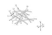
- the non-woven fabric 10 of the present embodiment shown in FIG. 1 is formed of a fiber 11.
- the fibers 11 are intertwined with each other, and there are portions that overlap in the thickness direction and / or portions (contact points) that are in contact with each other in the plane direction (in the XY plane) of the nonwoven fabric 10.
- the non-woven fabric 10 may include the fiber 11, and may include other fibers made of different materials in addition to the fiber 11.
- the non-woven fabric 10 has a structure in which a large number of fibers 11 are overlapped on the lower side in the thickness direction. Further, in FIG. 1, the first surface 10A is drawn along the XY plane, and the Z axis orthogonal to the XY plane is the thickness direction of the non-woven fabric 10.
- the fiber 11 has a wire diameter D1 formed to be substantially constant.
- the average (hereinafter referred to as the average wire diameter) DF (unit: ⁇ m) of the wire diameter D1 is preferably in the range of 0.10 ⁇ m or more and 5.00 ⁇ m or less.
- the average wire diameter DF is 0.10 ⁇ m or more, detachment of the fiber piece is suppressed as compared with the case where the average wire diameter DF is less than 0.10 ⁇ m. Suppression of desorption of fiber pieces means that desorption of fiber pieces from the non-woven fabric 10 is suppressed, and suppression of desorption of fiber pieces leads to excellent durability of the non-woven fabric 10. ..
- the non-woven fabric 10 contains the same volume ratio of air (hereinafter referred to as porosity) as compared with the case where it is larger than 5.00 ⁇ m. , Becomes softer. Further, since the average wire diameter DF is 5.00 ⁇ m or less, the porosity of the non-woven fabric 10 is larger than that in the case of larger than 5.00 ⁇ m even if the softness of the non-woven fabric 10 is about the same. The sound absorbing performance and heat insulating performance when used as a sound absorbing material and a heat insulating material are improved, and the amount of filtration treatment when used as a filter is increased.
- porosity volume ratio of air
- the average wire diameter DF is more preferably in the range of 0.15 ⁇ m or more and 4.00 ⁇ m or less, and further preferably in the range of 0.20 ⁇ m or more and 3.00 ⁇ m or less.
- the average wire diameter DF can be obtained by measuring the wire diameters of 100 fibers 11 from an image taken with a scanning electron microscope and calculating an average value.
- the non-woven fabric 10 is formed through a heating step 22 (see FIG. 2) in which the fiber aggregate 60 (see FIG. 2) in which the fibers 11 are collected is heated to the melting temperature Tm of the fibers 11.
- the heating step 22 residual stress (force accumulated in the fiber 11 at the time of collection and bending the fiber 11) is removed from the fiber assembly 60, and the fiber 11 is straightened. (It approaches a straight line from a curved state (the degree of straightness increases)).
- the non-woven fabric 10 has a degree of orientation of the fiber 11 of 1.1 or more and 1.3 or less due to the linearization by this heating.
- the degree of orientation of the fiber 11 functions as an index indicating the orientation of the fiber 11 (how much the orientation in the longitudinal direction is aligned), and the smaller the degree of orientation, the less the orientation of the fiber 11 is aligned (the orientation is lower). (Weaker), the larger the degree of orientation, the more aligned the orientations of the fibers 11 (stronger orientation). Specifically, when the degree of orientation is 1.0, it is almost non-oriented, and when the degree of orientation is 1.1 or more, it has orientation, and when the degree of orientation is 1.2 or more, it has strong orientation. It shows that it is.
- the effect is exhibited when the degree of orientation is 1.1 or more and 1.3 or less, preferably 1.15 or more and 1.25 or less, and more preferably 1.2 or more and 1.25 or less.
- the degree of orientation can be calculated using generally known image analysis software (see “http://psl.fp.a.u-tokyo.ac.jp/research02_04.html").
- the average line-to-line angle of the fiber 11 is close to 180 degrees accordingly.
- the average of the line-to-line angles is preferably 178 degrees or more and 182 degrees or less.
- the line-segment angle is a line segment connecting two adjacent contacts 12a and 12b among the contacts in which the first fiber 11A, which is one of the fibers 11 contained in the non-woven fabric 10, is in contact with the other fibers 11.
- a line segment connecting two adjacent contacts 13a and 13b among the contacts in which the second fiber 11B, which is one of the fibers 11 contained in the non-woven fabric 10, is in contact with the other fiber 11, is the second line segment.
- the non-woven fabric 10 has a large number of line segments corresponding to the first line segment 12 and the second line segment 13 described above, and of course, the line segment corresponding to the first line segment 12 and the first line segment. There are many combinations with line segments corresponding to the two line segments 13. For the average of the line-to-line angles, the line-to-line angle was obtained for each combination of the line segment corresponding to the first line segment 12 and the line segment corresponding to the second line segment 13, and the line-to-line angles obtained in this way were obtained. It is obtained by calculating the average of the angles.
- a plurality of voids 14 as a spatial region defined by the fiber 11 are formed as a portion where air exists.
- the plurality of voids 14 communicate with each other in the thickness direction Z of the nonwoven fabric 10, they form pores penetrating in the thickness direction Z of the nonwoven fabric 10.
- the pores function as holes in the filter.
- some of the voids 14 do not form pores and exist as a non-penetrating space region in the thickness direction, for example, a space region closed by the fiber 11.
- the porosity is preferably 90% or more (that is, at least 90%). Further, since the porosity can be increased up to 99%, the porosity is more preferably 90 to 99%, and particularly preferably 90 to 95%.
- it can be used as a sound absorbing material and a heat insulating material because it exhibits excellent sound absorbing performance and heat insulating performance as compared with the case where the porosity is less than 90%.
- the filter has a larger filtration treatment performance than the case where the porosity is less than 90%.
- the filtration treatment performance means the treatment amount per unit time and / or the sustainability of the state in which clogging is suppressed.
- the porosity (unit:%) is such that the non-woven fabric 10 is weighed at W (unit is g / m 2 ), the thickness is H (unit is mm), and the specific gravity of the fiber 11 is ⁇ 1 (unit is kg / m 3 ). When doing so, it can be obtained by [1- ⁇ (W / 1000) / (H / 1000) ⁇ / ⁇ 1] ⁇ 100. Weighing W is cut out non-woven fabric 10 to 5 cm ⁇ 5 cm, the mass measured by an electronic balance (manufactured by Mettler-Toledo, Inc.), a value obtained by converting the measured value per 1 m 2.
- the thickness H is measured by a non-contact laser displacement meter (LK-H025 manufactured by KEYENCE CORPORATION).
- the average pore diameter of the void 14 (hereinafter, average pore diameter DA) is preferably 5.0 ⁇ m or more (that is, at least 5.0 ⁇ m).
- the average pore size DA can be obtained by the following method. First, the fiber sheet 10 is cut into 5 cm squares (5 cm ⁇ 5 cm) and used as a sample. After immersing this sample in GALWICK (manufactured by POROUS MATERIAL) with a surface tension of 15.3 mN / m, the average pore size DA was measured by the bubble point method using a palm porosity meter (manufactured by POROUS MATERIAL). can get.
- the non-woven fabric 10 preferably has an average pore diameter DA of 5.0 ⁇ m or more and an average wire diameter DF of 1.0 ⁇ m or more (that is, at least 1.0 ⁇ m).
- the filter is used as compared with the case where the average wire diameter is less than 1.0 ⁇ m. Since it suppresses deformation with respect to the pressure of the fluid and exhibits stable filtration treatment performance, it is particularly suitable when the non-woven fabric 10 is used as a biofilter.
- the fiber 11 is formed of a resin (polymer) (the material (fiber material) of the fiber 11 is a polymer).
- a resin polymer
- the material (fiber material) of the fiber 11 is a polymer.
- cellulose-based polymer cycloolefin polymer (COP), polymethylmethacrylate, polyester, polyurethane, polyethylene (PE), elastoma, polypropylene polylactic acid, polystyrene, polycarbonate, acrylic resin, polyvinyl alcohol (PVA), gelatin, Examples thereof include polyimide, PEEK, liquid crystal polymer (LCP), and fluororesin.
- a cellulosic polymer is used as a material, it is preferably cellulosic acylate.
- Cellulose acylate is a cellulose ester in which some or all of the hydrogen atoms constituting the hydroxy group of cellulose are substituted with an acyl group.
- the cellulose acylate is preferably either cellulose acetate propionate (CAP) or cellulose triacetate (TAC).
- CAP cellulose acetate propionate
- TAC cellulose triacetate
- the polymer used as the material of such a fiber 11 is preferably a polymer that can be made into a solution by dissolving it in a solvent, and more preferably a polymer that can be made into a solution by being dissolved in an organic solvent.
- the degree of orientation of the fiber 11 is high (1.1 or more and 1.3 or less), and the line-to-line angles are also uniform. (Close to 180 degrees). Further, as the degree of orientation of the fiber 11 is high, the porosity is also high. As a result, suitable performance can be exhibited in various applications.
- the non-woven fabric 10 can be manufactured by, for example, the non-woven fabric manufacturing facility 20 shown in FIG.
- the non-woven fabric manufacturing facility 20 includes a fiber assembly manufacturing step 21 and a heating step 22.
- the fiber assembly manufacturing step 21 is for forming the fiber 11 and manufacturing the fiber assembly 60 by using the electric field spinning method.
- the fiber assembly manufacturing process 21 includes a solution preparation unit 23 and a fiber assembly manufacturing unit 24.
- the solution preparation unit 23 is for preparing the solution 23a forming the fiber 11.
- the solution preparation unit 23 prepares the solution 23a by dissolving the material (fiber material) of the fiber 11 in a solvent.
- the fiber assembly manufacturing unit 24 includes a nozzle unit 25, an integrated unit 26, and a power supply 27.
- the nozzle unit 25 is formed long in the width direction (direction perpendicular to the drawing) of the support 30 described later, and a plurality of nozzles 25a are arranged side by side along the longitudinal direction (that is, the width direction of the support 30). ing.
- the solution 23a prepared by the solution preparation unit 23 is supplied to each nozzle 25a, and the solution 23a is discharged from each nozzle 25a toward the integration unit 26.
- the collecting unit 26 has a collector 52, a support supply unit 57, and a support winding unit 58.
- the collector 52 is for attracting the solution 23a discharged from the nozzle 27 and collecting the formed fibers 11 to obtain the fiber aggregate 60.
- the fibers 11 are used as the support 30 described later. Collect on top.
- the collector 52 is composed of an endless belt formed of an annular metal strip, stretched over the rollers 61 and 62, and circulates and moves with the rotation of the rollers 61 and 62.
- a voltage is applied between the collector 52 and the nozzle unit 25 (nozzle 25a) by the power supply 27.
- one of the collector 52 and the nozzle 25a is positively (+) charged, and the other is negatively ( ⁇ ) charged.
- the solution 23a is attracted to the collector 52 side and ejected from the nozzle 25a toward the collector 52.
- the collector 52 may be made of a material that is charged by applying a voltage from the power supply 27, and is made of, for example, stainless steel.
- the support supply unit 57 supplies, for example, a support 30 made of a strip-shaped aluminum sheet to the collector 52.
- the support 30 moves with the movement of the collector 52 and passes below the nozzle unit 25.
- the fibers 11 ejected from the nozzle 25a are sequentially collected on the support 30 to form a strip-shaped fiber assembly 60.
- the support 30 is peeled off from the fiber assembly 60, and the support 30 is wound around the support winding portion 58.
- the fiber assembly 60 is conveyed to the heating step 22.
- the fiber 11 may be collected without the support 30 (the fiber assembly 60 is formed directly on the collector 52 without the support 30).
- the example of forming the fiber 11 (fiber assembly 60) by the electric field spinning method has been described, but the dissolution spinning method (the solution 23a from the nozzle 25a hangs down on the collector 52 due to its own weight, for example, regardless of the potential difference.
- the fiber 11 (fiber aggregate 60) may be formed by the method of forming the fiber 11).
- the heating step 22 includes a tenta 70 and a heating chamber 71.
- the tenta 70 includes support members 70a that support both sides of the fiber assembly 60 in the width direction, and is conveyed while being supported by the support members 70a on both sides of the fiber assembly 60, and is passed through the heating chamber 71.
- the support member 70a may be of a type in which the fiber assembly 60 is gripped by an openable / closable clip, or may be of a type in which a needle-shaped member is pierced into the fiber assembly 60 to support the fiber assembly 60. ..
- the heating chamber 71 is provided with a heater 72, and the fiber assembly 60 is heated by the heater 72 to reach the melting temperature Tm. Since the heating method of the fiber assembly 60 can be freely set, for example, the fiber assembly 60 may be heated by directly applying the heat from the heater 72 to the fiber assembly 60, or the heat from the heater 72 may be heated. May be blown toward the fiber assembly 60 by a blower, that is, hot air may be applied to heat the fiber assembly 60. By this heating, the fiber assembly 60 is softened and shrunk to become a non-woven fabric 10 (nonwoven fabric 10 is manufactured). Further, by this heating, residual stress is removed from the fiber assembly 60, and the fiber 11 is straightened. Then, as the fiber 11 is straightened, the degree of orientation of the fiber 11 is improved.
- the heating time required from reaching 90% of the melting temperature Tm of the fiber 11 (90 ° C. when the melting temperature Tm is 100 ° C.) to reaching the melting temperature Tm (hereinafter, The fiber assembly 60 is heated so that the heating time (sometimes referred to as heating time) is 15 seconds or more (that is, at least 15 seconds) and 500 seconds or less.
- the heating time is preferably 15 seconds to 180 seconds. By doing so, it is possible to reliably remove the residual stress and sufficiently improve the degree of orientation while suppressing film formation (a phenomenon in which the fiber 11 melts and the holes (voids) are closed).
- the degree of orientation can be 1.1 or more and 1.3 or less.
- cooling time 15 seconds or more (that is, at least 15 seconds) 500. It is preferably less than a second.
- the cooling time is more preferably 15 seconds to 180 seconds, and even more preferably 15 seconds to 60 seconds. By doing so, the residual stress can be reliably removed while maintaining more productivity.
- the thickness of the fiber assembly 60 (nonwoven fabric 10) after heating is maintained at a thickness of 50% or more (that is, at least 50%) of the thickness of the fiber assembly 60 before heating. , More preferably, it is maintained at a thickness of 80% or more. In other words, it is preferable to keep the heating to a extent that the thickness of 50% or more, more preferably 80% or more can be maintained. By doing so, it is possible to prevent the fiber assembly 60 from becoming a film.
- the distance between the support member 70a that supports one side of the fiber assembly 60 and the support member 70a that supports the other side of the fiber assembly 60 is maintained at a constant distance. Therefore, the fiber assembly 60 is prevented from shrinking in the width direction. Further, in the heating step 22 of this example, the transfer tension of the fiber assembly 60 (the force for pulling the fiber assembly 60 in the transfer direction) is controlled so that the fiber assembly 60 does not shrink in the transfer direction. .. That is, in the heating step 22 of this example, only the thickness changes (thinners) without changing the width and length of the fiber assembly 60. As described above, as the thickness decreases, filming also progresses, so the smaller the decrease in thickness, the more preferable.
- the thickness of the fiber assembly 60 (nonwoven fabric 10) after heating is preferably 50% or more, preferably 80% or more of the thickness of the fiber assembly 60 before heating. More preferable. Further, the thickness of the fiber assembly 60 (nonwoven fabric 10) after heating is preferably 80 to 95%, more preferably 90 to 95% of the thickness of the fiber assembly 60 before heating.
- the distance between the support member 70a that supports one side of the fiber assembly 60 and the support member 70a that supports the other side of the fiber assembly 60 is expanded.
- the fiber assembly 60 may be widened. By widening the fiber assembly 60 while heating it in this way, the linearity of the fiber 11 can be more reliably improved in the width direction. It is also possible to adjust the hole diameter (increase the hole diameter so as to obtain a desired hole diameter). In this way, when widening the width, it is preferable to widen the width within a range of 50% or less of the width of the fiber assembly 60 before the widening. By doing so, it is possible to suppress the shake of the non-woven fabric.
- Table 1 shows the manufacturing conditions of the non-woven fabrics in Examples 1 to 12 and Comparative Example 1.
- thickness change indicates the ratio of the thickness after heating to the thickness before heating.
- the “reached temperature” is “Tm” when the melting temperature reaches Tm, “Tm or more” when the melting temperature exceeds Tm, and “Tm” when the melting temperature Tm is not reached. Less than “.
- the “heating time” indicates the time required for heating from 90% of the melting temperature Tm to the melting temperature Tm.
- the “cooling time” indicates the time required for cooling from the melting temperature Tm to reaching 90% of the melting temperature Tm.
- “stretching” is described as “yes” when the fiber assembly 60 is widened by the tenta 70, and “none” when the fiber assembly 60 is not widened.
- Table 2 shows the verification results of verifying the non-woven fabrics of Examples 1 to 12 and Comparative Example 1 manufactured under the manufacturing conditions of Table 1.
- Table 2 for “average wire diameter”, “average pore diameter”, “degree of orientation”, and “inter-line angle”, the values obtained by calculating the actual values from the manufactured non-woven fabric are shown. ing.
- “uniformity of pore size distribution” “filter separation performance”, “biocompatibility”, “strength”, and “processing suitability”
- “A” is generally good when the product is good.
- the degree of orientation was high by taking a long time of 90% or more of the melting temperature Tm (both the heating time and the cooling time were set to 15 seconds or more). Moreover, it was found that the line-to-line angles were aligned (approaching 180 degrees). Further, in the heating step 22, it was found that by heating to a melting temperature of Tm or higher, the degree of orientation was high and the line-to-line angles were uniform. Further, it was found that the average pore diameter DA can be increased (film formation can be prevented) by setting the thickness change to 50% or more. It was also found that the average pore size DA can be increased by stretching (widening the fiber assembly 60).
Landscapes
- Engineering & Computer Science (AREA)
- Textile Engineering (AREA)
- Mechanical Engineering (AREA)
- Nonwoven Fabrics (AREA)
- Treatment Of Fiber Materials (AREA)
- Spinning Methods And Devices For Manufacturing Artificial Fibers (AREA)
- Filtering Materials (AREA)
Abstract
ファイバの配向度が高い不織布、不織布製造方法を提供する。 不織布製造設備(20)は、ファイバ集合体製造工程(21)と、加熱工程(22)と、を備えている。ファイバ集合体製造工程(21)は、電界紡糸法を用いてファイバ(11)を形成し、形成したファイバ(11)を捕集して、ファイバ集合体(60)を形成する。加熱工程(22)では、ファイバ(11)の融解温度Tmの90%に到達してから融解温度Tmに到達するまでの加熱所要時間が15秒以上となるように、ファイバ集合体(60)を加熱して、不織布(10)を形成する。形成された不織布(10)は、配向度が1.1以上1.3以下である。
Description
本発明は、不織布、不織布製造方法に関する。
ファイバで形成されている不織布として、下記特許文献1~4が知られている。不織布は、種々の分野における用途開発が盛んに行われている。期待される用途には例えば断熱材、吸音材、フィルタなどが挙げられ、また、医療用や細胞の足場材としての利用も期待される。不織布は、例えば、電界紡糸法により製造される。電界紡糸法は、エレクトロスピニング法などとも呼ばれ、溶媒にファイバ材が融解している溶液をコレクタへ向けて噴出させてファイバを形成し、噴出されたファイバを捕集することにより不織布を形成するものである。
不織布では、ファイバの配向度を向上させることで、空隙率の向上など良好な性能を発揮できる場合がある。しかしながら従来は、ファイバの直線度が低いなどの理由からファイバの配向度が低いといった問題があった。
本発明は、上記背景を鑑みてなされたものであり、ファイバの配向度が向上された不織布、及び、このような不織布を製造可能な不織布製造方法を提供することを目的としている。
上記目的を達成するために、本発明の不織布は、平均線径が0.10μm以上5.00μm以下の範囲内であるファイバを備え、ファイバの配向度が1.1以上1.3以下であるである。
空隙率が少なくとも90%であることが好ましい。
第1ファイバと他のファイバとの接点のうち隣り合う2つの接点を結ぶ第1線分と、第1ファイバとは別の第2ファイバと他のファイバとの接点のうち隣り合う2つの接点を結ぶ第2線分との角度である線間角度について、線間角度の平均が、178度以上182度以下の範囲内であることが好ましい。
ファイバが、セルロース系ポリマーで形成されていることが好ましい。
平均孔径が少なくとも5μmであり、平均線径が少なくとも1μmであることが好ましい。
また、上記目的を達成するために、本発明の不織布製造方法は、溶媒にファイバ材が溶解している溶液をコレクタへ向けて噴出させてファイバを形成し、ファイバを捕集することにより不織布を形成する不織布製造方法において、ファイバを捕集することによって形成されたファイバ集合体を加熱する加熱工程を備え、加熱工程では、ファイバの融解温度の90%の温度に到達してから融解温度に到達するまでの加熱所要時間を少なくとも15秒としている。
加熱工程では、融解温度に到達した後に冷却を行い、
冷却では、融解温度から融解温度の90%の温度に到達するまでの冷却所要時間を少なくとも15秒とすることが好ましい。
冷却では、融解温度から融解温度の90%の温度に到達するまでの冷却所要時間を少なくとも15秒とすることが好ましい。
加熱工程では、加熱後のファイバ集合体の厚みが加熱前のファイバ集合体の厚みの少なくとも50%の厚みに維持されることが好ましい。
加熱工程では、ファイバ集合体の厚み方向とは垂直な方向で対向するファイバ集合体の一方の側縁部と他方の側縁部とを、少なくとも一定間隔離間させて保持することが好ましい。
加熱工程では、一方の側縁部と他方の側縁部との間隔を加熱前よりも拡張させることが好ましい。
溶液とコレクタとの間に電圧を印加してファイバを噴出させることが好ましい。
本発明によれば、ファイバの配向度を向上させた不織布を得られる。
図1に示す本実施形態の不織布10は、ファイバ11で形成されている。ファイバ11同士は絡み合っており、厚み方向で重なる部分、及び/または、不織布10の面方向(XY平面内)において接している部分(接点)がある。接点には、ファイバ11同士が接着しているものと非接着のものとが存在する。不織布10は、ファイバ11を含んでいればよく、ファイバ11に加えて、素材が異なる他のファイバを備えてもよい。
なお、図1には、図の煩雑化を避けるために不織布10の厚み方向において一方の表面(以下、第1表面)10A側の一部のみを描いてある。したがって、不織布10は、厚み方向の下側に、さらに多数のファイバ11が重なった構造となっている。また、図1では、第1表面10AをXY平面に沿った状態に描いており、XY平面に直交するZ軸を不織布10の厚み方向としている。
ファイバ11は、線径D1が概ね一定に形成されている。線径D1の平均(以下、平均線径と称する)DF(単位はμm)は、0.10μm以上5.00μm以下の範囲内であることが好ましい。平均線径DFが0.10μm以上であることにより、0.10μm未満の場合と比べて、ファイバ片の脱離が抑制される。ファイバ片の脱離の抑制とは、不織布10からのファイバ片の脱離が抑制されることを意味し、ファイバ片の脱離が抑制されていることは不織布10としての優れた耐久性につながる。平均線径DFが5.00μm以下であることにより、5.00μmよりも大きい場合に比べて、不織布10は、含んでいる空気の体積割合(以下、空隙率と称する)が同じであっても、より柔らかくなる。また、平均線径DFが5.00μm以下であることにより、5.00μmよりも大きい場合に比べて、不織布10は柔らかさが同程度であっても、空隙率がより大きくなり、その結果、吸音材、断熱材として用いた場合の吸音性能、断熱性能が高くなり、また、フィルタに利用した場合のろ過処理量が高くなる。なお、平均線径DFは、0.15μm以上4.00μm以下の範囲内であることがより好ましく、0.20μm以上3.00μm以下の範囲内であることがさらに好ましい。平均線径DFは、走査型電子顕微鏡で撮影した画像から100本のファイバ11の線径を測定し、平均値を算出することにより求めることができる。
不織布10は、後述するように、ファイバ11を捕集したファイバ集合体60(図2参照)を、ファイバ11の融解温度Tmまで加熱する加熱工程22(図2参照)を経て形成されている。加熱工程22を経ることで、ファイバ集合体60から残留応力(捕集の際にファイバ11に蓄積された力であり、ファイバ11を湾曲させている力)が除去され、ファイバ11が直線化される(湾曲した状態からより直線に近づく(直線度が高まる))。そして、不織布10は、この加熱による直線化により、ファイバ11の配向度が1.1以上1.3以下となっている。
ファイバ11の配向度は、ファイバ11の配向性(長手方向の向きがどの程度揃っているか)を示す指標として機能し、配向度が小さいほどとファイバ11の向きが揃っておらず(配向性が弱く)、配向度が大きいほどファイバ11の向きが揃っている(配向性が強い)ことを示している。具体的には配向度が1.0である場合にはほぼ無配向であり、配向度が1.1以上で配向性を有し、配向度が1.2以上で強い配向性を有していることを示している。本発明では配向度が1.1以上1.3以下で効果を示し、1.15以上1.25以下が好ましく、1.2以上1.25以下がさらに好ましい。配向度は、一般に知られた画像解析ソフト(「http://psl.fp.a.u-tokyo.ac.jp/research02_04.html」参照)などを用いて算出できる。
このように、不織布10は、ファイバ11の配向度が高いので、これに伴ってファイバ11の線間角度の平均が180度に近い値となっている。ここで、線間角度の平均は、178度以上182度以下であることが好ましい。
線間角度は、不織布10に含まれるファイバ11のうちの1つである第1ファイバ11Aが他のファイバ11と接する接点のうち、隣り合う2つの接点12a、12bを結ぶ線分を第1線分12とし、不織布10に含まれるファイバ11のうちの1つである第2ファイバ11Bが他のファイバ11と接する接点のうち、隣り合う2つの接点13a、13bを結ぶ線分を第2線分13としたときに、第1線分12と第2線分13との角度(第1線分12に対する第2線分13の角度)を示している。不織布10には、前述した第1線分12に相当する線分、及び、第2線分13に相当する線分が多数存在し、当然ながら、第1線分12に相当する線分と第2線分13に相当する線分との組み合わせも多数存在する。線間角度の平均は、第1線分12に相当する線分と第2線分13に相当する線分との組み合わせのそれぞれについて線間角度を求め、このようにして求めた複数の線間角度の平均を算出することにより得られる。
不織布10には、ファイバ11によって画定された空間領域としての空隙14が、空気が存在する部分として複数形成されている。複数の空隙14は、不織布10の厚み方向Zにおいて連通している場合には、不織布10の厚み方向Zに貫通した空孔を形成する。この空孔は、不織布10を例えばフィルタに利用した場合には、フィルタの孔として機能する。また、空隙14の中には、空孔を形成せずに、厚み方向で非貫通、例えばファイバ11によって閉じられた空間領域として存在しているものもある。
そして、前述のように不織布10はファイバ11の配向度が高いので、これに伴って、空隙率も高くなっている。ここで、空隙率は90%以上(すなわち、少なくとも90%)であることが好ましい。また、空隙率は99%まで高くすることが可能であることから、空隙率は90~99%がさらに好ましく、90~95%が特に好ましい。このように空隙率を高くすること、すなわち、内部に多量の空気を含ませることで用途に広がりをもたせることができる。例えば、90%未満の空隙率である場合に比べて優れた吸音性能及び断熱性能を示すから、吸音材及び断熱材として利用できる。また、90%未満の空隙率である場合に比べて、フィルタにした場合には大きなろ過処理性能を示す。ろ過処理性能とは、単位時間あたりの処理量、及び/または、目詰まりが抑制された状態の持続性などを意味する。
空隙率(単位は%)は、不織布10の秤量をW(単位はg/m2)とし、厚みをH(単位はmm)とし、ファイバ11の比重をρ1(単位はkg/m3)とするときに、[1-{(W/1000)/(H/1000)}/ρ1]×100で求めることができる。秤量Wは、不織布10を5cm×5cmに切り出し、質量を電子天秤(メトラー・トレド株式会社製)で測定し、その測定値を1m2あたりに換算した値を用いる。厚みHは、本例では、非接触レーザー変位計(キーエンス株式会社製LK-H025)で測定している。
空隙14の孔径の平均(以下、平均孔径DA)は、5.0μm以上(すなわち、少なくとも5.0μm)であることが好ましい。なお、平均孔径DAは、以下の方法で求めることができる。まず、ファイバシート10から5cm角(5cm×5cm)に切り出し、サンプルとする。このサンプルを、表面張力が15.3mN/mのGALWICK(POROUS MATERIAL社製)に浸漬した後、パームポロメーター(POROUS MATERIAL社製)を用いて、バブルポイント法で測定することにより平均孔径DAは得られる。
なお、不織布10は、平均孔径DAが5.0μm以上であることに加え、前述した平均線径DFが1.0μm以上(すなわち、少なくとも1.0μm)であることが好ましい。このように、平均孔径DAが5.0μm以上であり、かつ、平均線径DFが1.0μm以上とすることで、1.0μm未満の平均線径である場合に比べて、フィルタにした場合には流体の圧力に対して変形を抑制し、安定したろ過処理性能を示すので、不織布10をバイオフィルタとして用いる場合に特に好適となる。
ファイバ11は、樹脂(ポリマー)から形成される(ファイバ11の素材(ファイバ材)はポリマーである)。具体的には、セルロース系ポリマー、シクロオレフィンポリマー(COP)、ポリメチルメタクリレート、ポリエステル、ポリウレタン、ポリエチレン(PE)、エラストマ、ポリプロピレンポリ乳酸、ポリスチレン、ポリカーボネート、アクリル樹脂、ポリビニルアルコール(PVA)、ゼラチン、ポリイミド、PEEK、液晶性ポリマー(LCP)、フッ素系樹脂などが挙げられる。セルロース系ポリマーを素材とする場合、セルロースアシレートであることが好ましい。セルロースアシレートは、セルロースのヒドロキシ基を構成する水素原子の一部または全部がアシル基で置換されているセルロースエステルである。セルロースアシレートは、セルロースアセテートプロピオネート(CAP)、セルローストリアセテート(TAC)のいずれかであることが好ましい。なお、このようなファイバ11の素材となるポリマーは、溶媒に溶解することにより溶液にできるポリマーであることが好ましく、有機溶媒に溶解することにより溶液にできるポリマーであることがより好ましい。
以上のように、不織布10は、ファイバ集合体60を加熱してファイバ11を直線化しているので、ファイバ11の配向度が高く(1.1以上1.3以下)、線間角度も揃っている(180度に近い)。また、ファイバ11の配向度が高いことに伴って、空隙率も高い。これにより、各種の用途において好適な性能を発揮することができる。
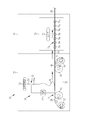
不織布10は、例えば、図2に示す不織布製造設備20により製造することができる。不織布製造設備20は、ファイバ集合体製造工程21と、加熱工程22とから構成される。ファイバ集合体製造工程21は、電界紡糸法を用いてファイバ11の形成及びファイバ集合体60の製造をするためのものである。
ファイバ集合体製造工程21は、溶液調製部23とファイバ集合体製造部24とを備える。溶液調製部23は、ファイバ11を形成する溶液23aを調製するためのものである。溶液調製部23は、ファイバ11の素材(ファイバ材)を、溶媒に溶解することにより、溶液23aを調製する。
ファイバ集合体製造部24は、ノズルユニット25と、集積部26と、電源27とを備える。ノズルユニット25は、後述する支持体30の幅方向(図と垂直な方向)に長く形成されており、長手方向(すなわち、支持体30の幅方向)に沿って複数のノズル25aが並べて配されている。各ノズル25aには、溶液調製部23によって調製された溶液23aが供給され、溶液23aは、各ノズル25aから集積部26へ向けて吐出される。
集積部26は、コレクタ52と、支持体供給部57と、支持体巻取部58とを有する。コレクタ52はノズル27から吐出された溶液23aを誘引し、形成されたファイバ11を捕集してファイバ集合体60を得るためのものであり、本実施形態では、ファイバ11を後述の支持体30上に捕集する。コレクタ52は、金属製の帯状物で環状に形成された無端ベルトで構成され、ローラ61、62に張り渡され、ローラ61、62の回転に伴って循環移動する。
コレクタ52とノズルユニット25(ノズル25a)との間には電源27により電圧が印加される。これにより、コレクタ52とノズル25aとのうち一方がプラス(+)に帯電し、他方がマイナス(-)に帯電する。こうすることで、溶液23aがコレクタ52側へ誘引され、ノズル25aからコレクタ52へ向けて噴出される。なお、コレクタ52は、電源27によって電圧が印加されることにより帯電する素材から形成されていればよく、例えば、ステンレス製とされる。
支持体供給部57は、例えば、帯状のアルミニウムシートからなる支持体30をコレクタ52に供給する。支持体30は、コレクタ52の移動に伴って移動し、ノズルユニット25の下方を通過する。この間に、ノズル25aから噴出したファイバ11が支持体30上に順次捕集されて帯状のファイバ集合体60が形成される。この後、ファイバ集合体60から支持体30が剥がされ、支持体30は、支持体巻取部58に巻き取られる。他方、ファイバ集合体60は、加熱工程22へと搬送される。なお、支持体30を介さずにファイバ11を捕集する構成(支持体30を介さずにコレクタ52上に直接ファイバ集合体60が形成される構成)としてもよい。また、本例では、電界紡糸法によりファイバ11(ファイバ集合体60)を形成する例で説明をしたが、溶解紡糸法(ノズル25aからの溶液23aが電位差によらず例えば自重によりコレクタ52に垂れることによりファイバ11を形成する方法)によりファイバ11(ファイバ集合体60)を形成してもよい。
加熱工程22は、テンタ70と、加熱室71とを備えている。テンタ70は、ファイバ集合体60の幅方向両側部を支持する支持部材70aを備え、支持部材70aによりファイバ集合体60の両側部を支持しながら搬送し、加熱室71を通過させる。なお、支持部材70aは、開閉自在のクリップによりファイバ集合体60を把持するタイプのものでもよいし、針状の部材をファイバ集合体60に刺してファイバ集合体60を支持するタイプのものでもよい。
加熱室71は、ヒータ72を備えており、ヒータ72によりファイバ集合体60を加熱し、融解温度Tmまで到達させる。なお、ファイバ集合体60の加熱方法は自由に設定できるので、例えば、ヒータ72からの熱を直接ファイバ集合体60に当てることによりファイバ集合体60を加熱してもよいし、ヒータ72からの熱を送風機によりファイバ集合体60へ向けて送風、すなわち、熱風を当ててファイバ集合体60を加熱してもよい。この加熱により、ファイバ集合体60が軟化・収縮して、不織布10となる(不織布10が製造される)。また、この加熱により、ファイバ集合体60から残留応力が除去され、ファイバ11が直線化される。そして、ファイバ11の直線化に伴って、ファイバ11の配向度が向上する。
しかし、加熱工程22における温度履歴(温度と時間との関係)によっては、良好な不織布を製造できない場合がある。例えば、短時間で融解温度Tmまで到達させてしまった場合には、残留応力が除去しきれずに配向度を十分に向上できない。このため、加熱工程22では、ファイバ11の融解温度Tmの90%(融解温度Tmが100℃である場合は、90℃)に到達してから融解温度Tmに到達するまでの加熱所要時間(以下、加熱時間と称する場合がある)が15秒以上(すなわち、少なくとも15秒)、500秒以下となるように、ファイバ集合体60を加熱している。加熱所要時間は15秒~180秒が好ましい。こうすることで、フイルム化(ファイバ11が融解して孔(空隙)が塞がってしまう現象)を抑制しつつ確実に残留応力を除去して配向度を十分に向上させること、具体的には、配向度を1.1以上1.3以下とすることが可能となる。
なお、加熱工程22において、ファイバ集合体60がファイバ11の融解温度Tmに到達した後は冷却(自然冷却であっても強制冷却であってもよい)することが好ましい。また、冷却においては、ファイバ11の融解温度Tmから融解温度Tmの90%に到達するまでの冷却所要時間(以下、冷却時間と称す場合がある)が15秒以上(すなわち、少なくとも15秒)500秒以下であることが好ましい。冷却所要時間は15秒~180秒がより好ましく、15秒~60秒がさらに好ましい。こうすることでより生産性を維持しつつ、確実に残留応力を除去できる。
一方、上述のように加熱時間及び/または冷却時間が長すぎると、すなわち、融解温度Tmの90%以上としている時間が長すぎると、ファイバ集合体60がフイルム化してしまうといった問題がある。このため、加熱工程22においては、加熱後のファイバ集合体60(不織布10)の厚みが加熱前のファイバ集合体60の厚みの50%以上(すなわち、少なくとも50%)の厚みに維持されること、より好ましくは80%以上の厚みに維持されることが好ましい。換言すると、50%以上、より好ましくは80%以上の厚みを維持可能な程度の加熱にとどめておくことが好ましい。こうすることで、ファイバ集合体60がフイルム化してしまうことを防止できる。
ここで、本例の加熱工程22では、ファイバ集合体60の一側部を支持する支持部材70aと、ファイバ集合体60の他側部を支持する支持部材70aとの間隔を一定間隔に保つことで、ファイバ集合体60が幅方向に収縮しないようにしている。また、本例の加熱工程22では、ファイバ集合体60の搬送テンション(ファイバ集合体60を搬送方向に牽引する力)を制御することにより、ファイバ集合体60が搬送方向に収縮しないようにしている。すなわち、本例の加熱工程22では、ファイバ集合体60の幅及び長さは変わらずに厚みだけが変化する(薄くなる)。なお、前述のように、厚みが減少するほどフイルム化も進行してしまうため、厚みの減少は小さいほど好ましい。具体的には、前述のように、加熱後のファイバ集合体60(不織布10)の厚みが加熱前のファイバ集合体60の厚みの50%以上であることが好ましく、80%以上であることがより好ましい。さらには、加熱後のファイバ集合体60(不織布10)の厚みが加熱前のファイバ集合体60の厚みの80~95%であることが好ましく、90~95%であることがより好ましい。
なお、加熱工程22で加熱している間に、ファイバ集合体60の一側部を支持する支持部材70aと、ファイバ集合体60の他側部を支持する支持部材70aとの間隔を拡張し、ファイバ集合体60を拡幅させてもよい。このようにファイバ集合体60を加熱しながら拡幅することにより、幅方向についてファイバ11の直線性をより確実に高めることができる。また、孔径を調整すること(所望の孔径となるように孔径を大きくすること)も可能である。このように、拡幅を行う場合、拡幅前のファイバ集合体60の幅の50%以下の範囲で拡幅を行うことが好ましい。こうすることで不織布のやぶれを抑制できる。
以下、本発明の効果を検証した検証結果について説明する。検証では、図2に示す不織布製造設備20を用い、ファイバの素材、加熱工程における温度履歴などを異ならせて14種類の不織布を製造した。そして、製造の過程で、本発明の要件を満たす温度履歴で加熱、すなわち、融解温度Tmの90%から融解温度Tmに達するまでの加熱時間を15秒以上としたものを実施例(実施例1~12)とし、これ以外の温度履歴で加熱を行ったものを比較例(比較例1)とした(表1、表2参照)。
表1に、実施例1~12並びに比較例1における不織布の製造条件を示す。なお、表1において、「厚み変化」は、加熱前の厚みに対する加熱後の厚みの割合を記している。また、「到達温度」は、融解温度Tmまで到達させた場合は「Tm」、融解温度Tmを超える温度まで到達させた場合は「Tm以上」、融解温度Tmまで到達させていない場合は「Tm未満」と記している。さらに、「加熱時間」は、融解温度Tmの90%から融解温度Tmに達するまでの加熱所要時間を示している。また、「冷却時間」は、融解温度Tmから融解温度Tmの90%に達するまでの冷却所要時間を示している。さらに、「延伸」は、テンタ70でファイバ集合体60の拡幅を行った場合は「あり」、拡幅を行わなかった場合は「なし」と記している。

表2に、表1の製造条件で製造された実施例1~12並びに比較例1の不織布を検証した検証結果を示す。なお、表2において、「平均線径」、「平均孔径」、「配向度」、及び、「線間角度」については、製造された不織布から実際の値を算出することにより得た値を記している。また、「孔径分布の均一性」、「フィルタの分離性能」、「生体適合性」、「強度」、及び、「加工適正」については、製品として良好である場合は「A」、概ね良好である場合は「B」、問題のないレベルである場合は「C」、問題があるが小さな問題である場合は「D」、大きな問題がある場合は「E」と記している。
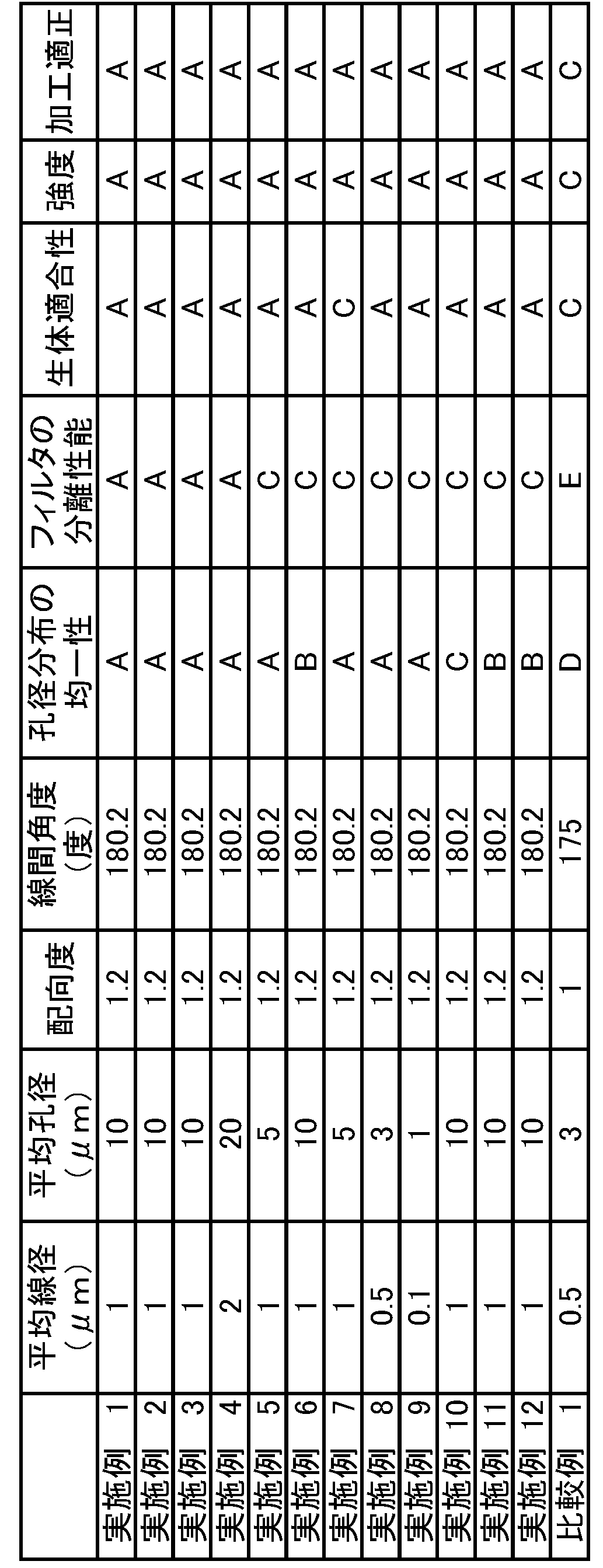
表2に示すように、検証により、加熱工程22において、融解温度Tmの90%以上としている時間を長くとる(加熱時間及び冷却時間をともに15秒以上とする)ことにより、配向度が高く、かつ、線間角度が揃う(180度に近づく)ことが判った。また、加熱工程22において、融解温度Tm以上に加熱することにより、配向度が高く、かつ、線間角度が揃うことが判った。さらに、厚み変化を50%以上とすることにより、平均孔径DAを大きくできる(フイルム化を防止できる)ことが判った。また、延伸を行う(ファイバ集合体60を拡幅させる)ことで、平均孔径DAを大きくできることが判った。
10 不織布
10A 第1表面
11 ファイバ
11A 第1ファイバ
11B 第2ファイバ
12 第1線分
12a、12b 接点
13 第2線分
13a、13b 接点
14 空隙
20 不織布製造設備
21 ファイバ集合体製造工程
22 加熱工程
23 溶液調製部
23a 溶液
24 ファイバ集合体製造部
25 ノズルユニット
25a ノズル
26 集積部
27 電源
30 支持体
52 コレクタ
57 支持体供給部
58 支持体巻取部
60 ファイバ集合体
61、62 ローラ
70 テンタ
70a 支持部材
71 加熱室
72 ヒータ
D1 線径
DF 平均線径
DA 平均孔径
Tm 融解温度
10A 第1表面
11 ファイバ
11A 第1ファイバ
11B 第2ファイバ
12 第1線分
12a、12b 接点
13 第2線分
13a、13b 接点
14 空隙
20 不織布製造設備
21 ファイバ集合体製造工程
22 加熱工程
23 溶液調製部
23a 溶液
24 ファイバ集合体製造部
25 ノズルユニット
25a ノズル
26 集積部
27 電源
30 支持体
52 コレクタ
57 支持体供給部
58 支持体巻取部
60 ファイバ集合体
61、62 ローラ
70 テンタ
70a 支持部材
71 加熱室
72 ヒータ
D1 線径
DF 平均線径
DA 平均孔径
Tm 融解温度
Claims (11)
- 平均線径が0.10μm以上5.00μm以下の範囲内であるファイバを備え、前記ファイバの配向度が1.1以上1.3以下である不織布。
- 空隙率が少なくとも90%である請求項1記載の不織布。
- 第1ファイバと他のファイバとの接点のうち隣り合う2つの接点を結ぶ第1線分と、前記第1ファイバとは別の第2ファイバと他のファイバとの接点のうち隣り合う2つの接点を結ぶ第2線分との角度である線間角度について、前記線間角度の平均が、178度以上182度以下の範囲内である請求項1または2記載の不織布。
- 前記ファイバが、セルロース系ポリマーで形成されている請求項1~3のいずれか1項に記載の不織布。
- 平均孔径が少なくとも5μmであり、前記平均線径が少なくとも1μmである請求項1~4のいずれか1項に記載の不織布。
- 溶媒にファイバ材が溶解している溶液をコレクタへ向けて噴出させてファイバを形成し、前記ファイバを捕集することにより不織布を形成する不織布製造方法において、
前記ファイバを捕集することによって形成されたファイバ集合体を加熱する加熱工程を備え、
前記加熱工程では、前記ファイバの融解温度の90%の温度に到達してから前記融解温度に到達するまでの加熱所要時間を少なくとも15秒とした不織布製造方法。 - 前記加熱工程では、前記融解温度に到達した後に冷却を行い、
前記冷却では、前記融解温度から前記融解温度の90%の温度に到達するまでの冷却所要時間を少なくとも15秒とした請求項6記載の不織布製造方法。 - 前記加熱工程では、加熱後の前記ファイバ集合体の厚みが加熱前の前記ファイバ集合体の厚みの少なくとも50%の厚みに維持される請求項6または7記載の不織布製造方法。
- 前記加熱工程では、前記ファイバ集合体の厚み方向とは垂直な方向で対向する前記ファイバ集合体の一方の側縁部と他方の側縁部とを、少なくとも一定間隔離間させて保持する請求項6~8のいずれか1項に記載の不織布製造方法
- 前記加熱工程では、前記一方の側縁部と前記他方の側縁部との間隔を加熱前よりも拡張させる請求項9記載の不織布製造方法。
- 前記溶液と前記コレクタとの間に電圧を印加して前記ファイバを噴出させる請求項6~10のいずれか1項に記載の不織布製造方法。
Priority Applications (1)
| Application Number | Priority Date | Filing Date | Title |
|---|---|---|---|
| JP2021504883A JP7167302B2 (ja) | 2019-03-12 | 2020-02-20 | 不織布製造方法 |
Applications Claiming Priority (2)
| Application Number | Priority Date | Filing Date | Title |
|---|---|---|---|
| JP2019045228 | 2019-03-12 | ||
| JP2019-045228 | 2019-03-12 |
Publications (1)
| Publication Number | Publication Date |
|---|---|
| WO2020184136A1 true WO2020184136A1 (ja) | 2020-09-17 |
Family
ID=72427634
Family Applications (1)
| Application Number | Title | Priority Date | Filing Date |
|---|---|---|---|
| PCT/JP2020/006827 Ceased WO2020184136A1 (ja) | 2019-03-12 | 2020-02-20 | 不織布、不織布製造方法 |
Country Status (2)
| Country | Link |
|---|---|
| JP (1) | JP7167302B2 (ja) |
| WO (1) | WO2020184136A1 (ja) |
Cited By (1)
| Publication number | Priority date | Publication date | Assignee | Title |
|---|---|---|---|---|
| JPWO2021172025A1 (ja) * | 2020-02-25 | 2021-09-02 |
Citations (5)
| Publication number | Priority date | Publication date | Assignee | Title |
|---|---|---|---|---|
| JPH10204767A (ja) * | 1996-11-19 | 1998-08-04 | Nippon Petrochem Co Ltd | 縦延伸不織布およびその製法 |
| JP2009102778A (ja) * | 2007-10-25 | 2009-05-14 | Mecc Co Ltd | 金属光沢繊維集合体およびその製造方法 |
| JP2016053229A (ja) * | 2014-09-04 | 2016-04-14 | 富士フイルム株式会社 | ナノファイバ製造方法及び装置、不織布製造方法 |
| WO2017158868A1 (ja) * | 2016-03-16 | 2017-09-21 | 株式会社 東芝 | 繊維配向シート、及びその製造方法 |
| WO2018097326A1 (ja) * | 2016-11-28 | 2018-05-31 | Jxtgエネルギー株式会社 | 吸音材用不織布及びそれを用いた吸音材 |
-
2020
- 2020-02-20 WO PCT/JP2020/006827 patent/WO2020184136A1/ja not_active Ceased
- 2020-02-20 JP JP2021504883A patent/JP7167302B2/ja active Active
Patent Citations (5)
| Publication number | Priority date | Publication date | Assignee | Title |
|---|---|---|---|---|
| JPH10204767A (ja) * | 1996-11-19 | 1998-08-04 | Nippon Petrochem Co Ltd | 縦延伸不織布およびその製法 |
| JP2009102778A (ja) * | 2007-10-25 | 2009-05-14 | Mecc Co Ltd | 金属光沢繊維集合体およびその製造方法 |
| JP2016053229A (ja) * | 2014-09-04 | 2016-04-14 | 富士フイルム株式会社 | ナノファイバ製造方法及び装置、不織布製造方法 |
| WO2017158868A1 (ja) * | 2016-03-16 | 2017-09-21 | 株式会社 東芝 | 繊維配向シート、及びその製造方法 |
| WO2018097326A1 (ja) * | 2016-11-28 | 2018-05-31 | Jxtgエネルギー株式会社 | 吸音材用不織布及びそれを用いた吸音材 |
Cited By (2)
| Publication number | Priority date | Publication date | Assignee | Title |
|---|---|---|---|---|
| JPWO2021172025A1 (ja) * | 2020-02-25 | 2021-09-02 | ||
| JP7345044B2 (ja) | 2020-02-25 | 2023-09-14 | 富士フイルム株式会社 | 不織布、不織布製造方法 |
Also Published As
| Publication number | Publication date |
|---|---|
| JPWO2020184136A1 (ja) | 2021-12-16 |
| JP7167302B2 (ja) | 2022-11-08 |
Similar Documents
| Publication | Publication Date | Title |
|---|---|---|
| JP5738928B2 (ja) | 高粘度材料を含むptfeのエレクトロスピニング | |
| JP6269922B2 (ja) | 繊維シート及びこれを用いた繊維製品 | |
| CN107366089B (zh) | 无纺布以及吸声材料 | |
| JP7033233B2 (ja) | 電界紡糸装置及び繊維シートの製造方法 | |
| CN101501262A (zh) | 微细纤维集合体的制造方法 | |
| CN110291241B (zh) | 片材及片材制造方法 | |
| WO2020184136A1 (ja) | 不織布、不織布製造方法 | |
| EP3460115B1 (en) | Sheet of oriented fibers and production process therefor | |
| CN107109736A (zh) | 自粘性无纺布 | |
| JP5277109B2 (ja) | 極細繊維不織布の製造方法及び極細繊維不織布 | |
| JP7345044B2 (ja) | 不織布、不織布製造方法 | |
| JP7214742B2 (ja) | 不織布 | |
| CN108905638A (zh) | 一种高效膜过滤材料的制备方法 | |
| JP2006152479A (ja) | 極細繊維の製造装置およびそれを用いた製造方法 | |
| JP2009028503A (ja) | 清掃用シート材 | |
| JP2023177489A (ja) | 不織布とその製造方法、および、固体電解質シート | |
| JP2016160568A (ja) | 不織布およびその製造方法 | |
| JP7440650B2 (ja) | 不織布、不織布製造方法、液体用フィルタ | |
| JP6897085B2 (ja) | 分割型複合繊維 | |
| JP7508543B2 (ja) | 不織布製造方法 | |
| JP2017101347A (ja) | 積層不織布の製造装置 | |
| JP2013023779A (ja) | 切断物の製造方法 | |
| JP2009161889A (ja) | スパンボンドウェブの製造装置 | |
| JP2011177986A (ja) | シート、及び、巻物 | |
| JP5449583B2 (ja) | 極細繊維不織布の製造方法及び極細繊維不織布 |
Legal Events
| Date | Code | Title | Description |
|---|---|---|---|
| 121 | Ep: the epo has been informed by wipo that ep was designated in this application |
Ref document number: 20770066 Country of ref document: EP Kind code of ref document: A1 |
|
| ENP | Entry into the national phase |
Ref document number: 2021504883 Country of ref document: JP Kind code of ref document: A |
|
| NENP | Non-entry into the national phase |
Ref country code: DE |
|
| 122 | Ep: pct application non-entry in european phase |
Ref document number: 20770066 Country of ref document: EP Kind code of ref document: A1 |