WO2017158868A1 - 繊維配向シート、及びその製造方法 - Google Patents
繊維配向シート、及びその製造方法 Download PDFInfo
- Publication number
- WO2017158868A1 WO2017158868A1 PCT/JP2016/075496 JP2016075496W WO2017158868A1 WO 2017158868 A1 WO2017158868 A1 WO 2017158868A1 JP 2016075496 W JP2016075496 W JP 2016075496W WO 2017158868 A1 WO2017158868 A1 WO 2017158868A1
- Authority
- WO
- WIPO (PCT)
- Prior art keywords
- fiber
- fibers
- deposit
- sheet
- fiber orientation
- Prior art date
Links
Images


Classifications
-
- D—TEXTILES; PAPER
- D04—BRAIDING; LACE-MAKING; KNITTING; TRIMMINGS; NON-WOVEN FABRICS
- D04H—MAKING TEXTILE FABRICS, e.g. FROM FIBRES OR FILAMENTARY MATERIAL; FABRICS MADE BY SUCH PROCESSES OR APPARATUS, e.g. FELTS, NON-WOVEN FABRICS; COTTON-WOOL; WADDING ; NON-WOVEN FABRICS FROM STAPLE FIBRES, FILAMENTS OR YARNS, BONDED WITH AT LEAST ONE WEB-LIKE MATERIAL DURING THEIR CONSOLIDATION
- D04H1/00—Non-woven fabrics formed wholly or mainly of staple fibres or like relatively short fibres
- D04H1/70—Non-woven fabrics formed wholly or mainly of staple fibres or like relatively short fibres characterised by the method of forming fleeces or layers, e.g. reorientation of fibres
- D04H1/72—Non-woven fabrics formed wholly or mainly of staple fibres or like relatively short fibres characterised by the method of forming fleeces or layers, e.g. reorientation of fibres the fibres being randomly arranged
- D04H1/728—Non-woven fabrics formed wholly or mainly of staple fibres or like relatively short fibres characterised by the method of forming fleeces or layers, e.g. reorientation of fibres the fibres being randomly arranged by electro-spinning
-
- D—TEXTILES; PAPER
- D01—NATURAL OR MAN-MADE THREADS OR FIBRES; SPINNING
- D01D—MECHANICAL METHODS OR APPARATUS IN THE MANUFACTURE OF ARTIFICIAL FILAMENTS, THREADS, FIBRES, BRISTLES OR RIBBONS
- D01D5/00—Formation of filaments, threads, or the like
- D01D5/0007—Electro-spinning
- D01D5/0015—Electro-spinning characterised by the initial state of the material
- D01D5/003—Electro-spinning characterised by the initial state of the material the material being a polymer solution or dispersion
-
- D—TEXTILES; PAPER
- D04—BRAIDING; LACE-MAKING; KNITTING; TRIMMINGS; NON-WOVEN FABRICS
- D04H—MAKING TEXTILE FABRICS, e.g. FROM FIBRES OR FILAMENTARY MATERIAL; FABRICS MADE BY SUCH PROCESSES OR APPARATUS, e.g. FELTS, NON-WOVEN FABRICS; COTTON-WOOL; WADDING ; NON-WOVEN FABRICS FROM STAPLE FIBRES, FILAMENTS OR YARNS, BONDED WITH AT LEAST ONE WEB-LIKE MATERIAL DURING THEIR CONSOLIDATION
- D04H1/00—Non-woven fabrics formed wholly or mainly of staple fibres or like relatively short fibres
- D04H1/04—Non-woven fabrics formed wholly or mainly of staple fibres or like relatively short fibres from fleeces or layers composed of fibres having existing or potential cohesive properties, e.g. natural fibres, prestretched or fibrillated artificial fibres
- D04H1/30—Collagen
-
- D—TEXTILES; PAPER
- D04—BRAIDING; LACE-MAKING; KNITTING; TRIMMINGS; NON-WOVEN FABRICS
- D04H—MAKING TEXTILE FABRICS, e.g. FROM FIBRES OR FILAMENTARY MATERIAL; FABRICS MADE BY SUCH PROCESSES OR APPARATUS, e.g. FELTS, NON-WOVEN FABRICS; COTTON-WOOL; WADDING ; NON-WOVEN FABRICS FROM STAPLE FIBRES, FILAMENTS OR YARNS, BONDED WITH AT LEAST ONE WEB-LIKE MATERIAL DURING THEIR CONSOLIDATION
- D04H1/00—Non-woven fabrics formed wholly or mainly of staple fibres or like relatively short fibres
- D04H1/40—Non-woven fabrics formed wholly or mainly of staple fibres or like relatively short fibres from fleeces or layers composed of fibres without existing or potential cohesive properties
- D04H1/54—Non-woven fabrics formed wholly or mainly of staple fibres or like relatively short fibres from fleeces or layers composed of fibres without existing or potential cohesive properties by welding together the fibres, e.g. by partially melting or dissolving
- D04H1/552—Non-woven fabrics formed wholly or mainly of staple fibres or like relatively short fibres from fleeces or layers composed of fibres without existing or potential cohesive properties by welding together the fibres, e.g. by partially melting or dissolving by applying solvents or auxiliary agents
-
- D—TEXTILES; PAPER
- D04—BRAIDING; LACE-MAKING; KNITTING; TRIMMINGS; NON-WOVEN FABRICS
- D04H—MAKING TEXTILE FABRICS, e.g. FROM FIBRES OR FILAMENTARY MATERIAL; FABRICS MADE BY SUCH PROCESSES OR APPARATUS, e.g. FELTS, NON-WOVEN FABRICS; COTTON-WOOL; WADDING ; NON-WOVEN FABRICS FROM STAPLE FIBRES, FILAMENTS OR YARNS, BONDED WITH AT LEAST ONE WEB-LIKE MATERIAL DURING THEIR CONSOLIDATION
- D04H1/00—Non-woven fabrics formed wholly or mainly of staple fibres or like relatively short fibres
- D04H1/70—Non-woven fabrics formed wholly or mainly of staple fibres or like relatively short fibres characterised by the method of forming fleeces or layers, e.g. reorientation of fibres
- D04H1/74—Non-woven fabrics formed wholly or mainly of staple fibres or like relatively short fibres characterised by the method of forming fleeces or layers, e.g. reorientation of fibres the fibres being orientated, e.g. in parallel (anisotropic fleeces)
-
- D—TEXTILES; PAPER
- D01—NATURAL OR MAN-MADE THREADS OR FIBRES; SPINNING
- D01F—CHEMICAL FEATURES IN THE MANUFACTURE OF ARTIFICIAL FILAMENTS, THREADS, FIBRES, BRISTLES OR RIBBONS; APPARATUS SPECIALLY ADAPTED FOR THE MANUFACTURE OF CARBON FILAMENTS
- D01F4/00—Monocomponent artificial filaments or the like of proteins; Manufacture thereof
Definitions
- Embodiment of this invention is related with a fiber orientation sheet and its manufacturing method.
- a deposit formed by forming fine fibers using an electrospinning method also referred to as an electrospinning method, a charge induction spinning method, and the like
- an electrospinning method also referred to as an electrospinning method, a charge induction spinning method, and the like
- the fiber formed using the electrospinning method has a low tensile strength
- the tensile strength of the deposit is also low.
- the deposit is formed by randomly depositing fibers, the anisotropy of tensile strength cannot be increased. Therefore, it has been desired to develop a sheet having high tensile strength and high tensile strength anisotropy.
- the problem to be solved by the present invention is to provide a fiber orientation sheet having high tensile strength and high tensile strength anisotropy, and a method for producing the same.
- the contained fibers are in close contact, the tensile strength in the first direction is F1, and the tensile strength in the second direction orthogonal to the first direction is F2.
- F1 is 1 MPa or more.
- F2 / F1 is 2 or more.
- FIG. 1 is a schematic diagram for illustrating an electrospinning apparatus 1.
- FIG. (A) is an electron micrograph in the case where the fibers 6 are deposited on a stationary plate-like collection part.
- (B) is an electron micrograph in the case where the fibers 6 are deposited on the rotating collection unit 4.
- (A), (b) is a model perspective view for illustrating the state before drying.
- (A), (b) is a schematic perspective view for demonstrating the case where it dries in the state which slips between the deposit body 7 and the base 100.
- FIG. (A), (b) is a schematic perspective view for demonstrating the case where it dries in the state which is hard to produce slip between the deposit body 7 and the base 100.
- FIG. (A) is an electron micrograph of the deposit 7.
- FIG. 7A is an electron micrograph of the fiber orientation sheets 70a and 70b.
- FIGS. 7A and 7B are optical micrographs of the fiber orientation sheets 70a and 70b. It is a schematic diagram for illustrating the orientation of collagen molecules in the fiber 6 formed by the electrospinning apparatus 1.
- (A) to (d) are atomic force micrographs of the surface of the fiber 6. It is a schematic diagram for illustrating the test pieces C and D used for a tensile test.
- (A) is a photograph for illustrating the state of a tensile test.
- (A) is an optical micrograph of the test piece D.
- FIG. It is a graph for comparing the result of the tensile test of the deposit 7 and the result of the tensile test of the fiber orientation sheets 70a and 70b.
- the fiber orientation sheet according to the present embodiment includes fibers.
- the fibers can be formed using, for example, an electrospinning method.
- the fiber contains a polymer material.
- Polymer materials include, for example, polypropylene, polyethylene, polystyrene, polyethylene terephthalate, polyvinyl chloride, polycarbonate, nylon, aramid, polyacrylate, polymethacrylate, polyimide, polyamideimide, polyvinylidene fluoride, polyethersulfone, and other industrial materials, collagen Biocompatible materials such as laminin, gelatin, polyacrylonitrile, chitin, polyglycolic acid and polylactic acid.
- the polymer substance is not limited to those illustrated.
- the fibers are in close contact with each other.
- a part of the fibers may be melted, and the fibers may be welded in the melted part. Therefore, in this specification, the state in which the fibers are in close contact with each other and the state in which the fibers are in close contact with each other and further partially welded are referred to as “contact state”.
- the contained fibers are in a close contact state, so that it is difficult to measure the fiber diameter (see FIG. 6B).
- fibers in close contact exist from the anisotropy of tensile strength described later and the direction in which the long axis of the molecule extends.
- the diameter dimension of the fibers included in the fiber orientation sheet can be the diameter dimension of the fibers included in the deposit.
- the average diameter of the fibers contained in the deposited body can be 0.05 ⁇ m or more and 5 ⁇ m or less.
- an electron micrograph of the surface of the deposit 7 described later is taken (see FIG. 6A), and any 100 fibers confirmed by the electron micrograph It can obtain
- the voids contained in the fiber orientation sheet are small.
- gap contained in a fiber orientation sheet is less than 0.5 micrometer, for example.
- the maximum dimension of the void can be obtained, for example, by taking an electron micrograph of the surface of the fiber orientation sheet and measuring the dimension of the void confirmed by the electron micrograph.
- the tensile strength of the fiber orientation sheet can be increased.
- the tensile strength can be measured by a constant speed extension type tensile tester or the like. In this case, the tensile strength can be measured according to, for example, JIS P8113.
- the extending direction of the fibers is almost uniform. That is, in the fiber-oriented sheet, the fibers extend in substantially the same direction. In this specification, the fibers extending in approximately the same direction is referred to as being “oriented”. If the fiber is “oriented”, the tensile strength of the fiber-oriented sheet in the direction in which the fiber extends increases. On the other hand, the tensile strength of the fiber orientation sheet in the direction orthogonal to the direction in which the fibers extend is low. Therefore, the tensile strength of the fiber-oriented sheet can be made anisotropic.
- the low tensile strength of the fiber orientation sheet in the direction orthogonal to the direction in which the fibers extend can cause the sheet to have insufficient mechanical strength, which may make it difficult to carry it in the apparatus, perform culture experiments, and perform surgical treatment. If the contained fibers are in close contact, the tensile strength of the fiber orientation sheet in the direction perpendicular to the direction in which the fibers extend can be increased.
- the tensile strength of the fiber orientation sheet in one direction is F1
- the tensile strength of the fiber orientation sheet in a direction orthogonal to this direction is In the case of F2, F1 in the fiber orientation sheet according to the present embodiment is 1 MPa or more, and F2 / F1 is 2 or more. However, F2> F1.
- the deposit formed by randomly depositing fibers has a low tensile strength, and the anisotropy of the tensile strength of the deposit is low (the tensile strength of the deposit is high isotropic).
- the above-mentioned F2 / F1 is about 6 to 10, but F1 is less than 1 MPa, and the material is easy to tear. Therefore, if F2 / F1 is calculated
- the degree of fiber orientation is high (F2 / F1 is large). Since the fiber orientation sheet according to the present embodiment has a high degree of fiber orientation, it can be applied to a specific technical field or application. As an example, high tensile strength and molecular orientation can be provided in the fiber orientation direction. Moreover, a high elongation characteristic can be given to the direction orthogonal to the fiber orientation.
- the direction in which the long axis of the molecule extends tends to be the direction in which the polymer material (fiber) extends. Therefore, by examining the direction in which the long axis of the molecule extends on the surface of the fiber-oriented sheet, it can be seen whether the fiber extends, and thus whether the fiber is oriented.
- the direction in which the long axis of the molecule extends can be known by using a structure determination method corresponding to the type of polymer substance. For example, Raman spectroscopy can be used in the case of polystyrene or the like, and polarized light absorbance analysis can be used in the case of polyimide or the like.
- the polymer substance is an organic compound having an amide group such as collagen
- the polarization FT-IR-ATR method which is a kind of infrared spectroscopy, is used to know the direction in which the long axis of the molecule extends, and thus whether the fiber is oriented. be able to.
- the surface of the fiber orientation sheet can be analyzed by the polarized FT-IR-ATR method as follows to determine the direction in which the long axis of the molecule extends.
- the absorption intensity when the wave number is 1640 cm ⁇ 1 is T1
- the absorption intensity when the wave number is 1540 cm ⁇ 1 is T2.
- the absorption intensity T1 is an absorption intensity in a direction orthogonal to the direction in which the long axis of the molecule extends.
- the absorption intensity T2 is the absorption intensity in the direction in which the long axis of the molecule extends. Therefore, it can be seen that if the absorbance ratio R1 (T1 / T2) in a predetermined polarization direction is small, there are many molecules extending in the polarization direction.
- the absorbance ratio R1 in a predetermined polarization direction and the absorbance ratio R2 when the orientation of the fiber orientation sheet is changed are obtained, and R1 / R2 is determined as the orientation degree. It can be a parameter. However, R1> R2.
- R1 / R2 increases. For example, as will be described later, R1 / R2 is 1.1 or more.
- That R1 / R2 is large means that the direction in which the long axis of the molecule extends is aligned. Further, as described above, in the stretched polymer substance, the direction in which the long axis of the molecule extends tends to be the direction in which the fiber extends. Therefore, the fact that R1 / R2 is large means that the fibers are oriented (the direction in which the fibers extend is aligned).
- the fiber orientation sheet according to the present embodiment has the same direction in which the major axes of the molecules of the polymer substance contained in the fibers extend (R1 / R2 is large), it is also applied to a specific technical field or application. It becomes possible.
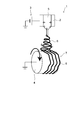
- FIG. 1 is a schematic view for illustrating an electrospinning apparatus 1.
- the electrospinning apparatus 1 is provided with a nozzle 2, a power supply 3, and a collection unit 4.
- a hole for discharging the raw material liquid 5 is provided in the nozzle 2.
- the power source 3 applies a voltage having a predetermined polarity to the nozzle 2.
- the power supply 3 applies a voltage to the nozzle 2 so that the potential difference between the nozzle 2 and the collecting unit 4 is 10 kV or more.
- the polarity of the voltage applied to the nozzle 2 can be positive or negative.
- the power supply 3 illustrated in FIG. 1 applies a positive voltage to the nozzle 2.
- the collecting unit 4 is provided on the side of the nozzle 2 where the raw material liquid 5 is discharged.
- the collecting unit 4 is grounded.
- a voltage having a reverse polarity to the voltage applied to the nozzle 2 may be applied to the collecting unit 4.
- the collection unit 4 has a columnar shape and is rotated.
- the raw material liquid 5 is obtained by dissolving a polymer substance in a solvent.
- a polymer substance there is no particular limitation on the polymer substance, and it can be appropriately changed according to the material of the fiber 6 to be formed.
- high molecular substances include industrial materials such as polypropylene, polyethylene, polystyrene, polyethylene terephthalate, polyvinyl chloride, polycarbonate, nylon and aramid, and biocompatible materials such as collagen, laminin, gelatin, polyacrylonitrile, chitin and polyglycolic acid. And so on.
- the solvent may be any solvent that can dissolve the polymer substance.
- the solvent can be appropriately changed according to the polymer substance to be dissolved.
- the solvent examples include water, alcohols (methanol, ethanol, isopropyl alcohol, trifluoroethanol, hexafluoro-2-propanol, etc.), acetone, benzene, toluene, cyclohexanone, N, N-dimethylacetamide, N, N-dimethyl. It may be formamide, N-methyl-2-pyrrolidone, dimethyl sulfoxide, and the like. Moreover, you may use additives, such as an inorganic electrolyte, an organic electrolyte, surfactant, and an antifoamer.
- the polymer substance and the solvent are not limited to those illustrated.
- the raw material liquid 5 remains in the vicinity of the discharge port of the nozzle 2 due to surface tension.
- the power source 3 applies a voltage to the nozzle 2. Then, the raw material liquid 5 in the vicinity of the discharge port is charged with a predetermined polarity. In the case illustrated in FIG. 1, the raw material liquid 5 in the vicinity of the discharge port is positively charged. Since the collecting unit 4 is grounded, an electric field is formed between the nozzle 2 and the collecting unit 4. When the electrostatic force acting along the lines of electric force becomes larger than the surface tension, the raw material liquid 5 in the vicinity of the discharge port is drawn toward the collection unit 4 by the electrostatic force. The drawn raw material liquid is stretched, and the fibers 6 are formed by volatilization of the solvent contained in the raw material liquid.
- the formed fiber 6 is deposited on the rotating collection unit 4 to form a deposit 7. Further, when the fibers 6 are deposited on the rotating collection unit 4, the fibers 6 are pulled in the rotation direction. That is, when the formed fibers 6 are deposited, the fibers 6 in the deposited body 7 are aligned in the direction in which the fibers 6 are mechanically pulled in one direction.
- the method of mechanically pulling the fiber 6 in one direction is not limited to the example illustrated.
- gas can be flowed in the direction in which the fibers 6 are drawn, and the fibers 6 can be mechanically pulled in one direction by the gas flow.
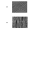
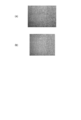
- FIG. 2A is an electron micrograph in the case where the fibers 6 are deposited on a stationary plate-like collection part.
- FIG. 2B is an electron micrograph when fibers 6 are deposited on the rotating collection unit 4.
- gap) between the fibers 6 can be decreased.
- a volatile liquid is supplied to the deposit 7.
- the deposit 7 is immersed in a volatile liquid.
- the fiber 6 does not melt
- the volatile liquid can be, for example, alcohols (methanol, ethanol, isopropyl alcohol, etc.), an alcohol aqueous solution, acetone, acetonitrile, ethylene glycol, or the like.
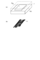
- FIGS. 3A and 3B are schematic perspective views for illustrating the state before drying.
- the deposit 7 containing a volatile liquid is placed on the base 100.
- the direction in which the fibers 6 extend is aligned to some extent, as shown in FIG.
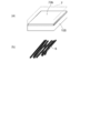
- FIGS. 4A and 4B are schematic perspective views for illustrating a case where drying is performed in a state where slippage occurs between the deposit 7 and the base 100.
- FIGS. 5A and 5B are schematic perspective views for illustrating a case where drying is performed in a state where slippage hardly occurs between the deposit 7 and the base 100.
- the slip between the deposit 7 and the base 100 can be controlled by the material of the fiber 6 and the material of the base 100. For example, when the material of the fiber 6 is collagen, slipping between the deposit 7 and the base 100 can be suppressed by using polystyrene as the base 100 material.
- the drying means there is no particular limitation on the drying means.
- the deposit 7 containing a volatile liquid may be dried in the atmosphere (natural drying), heated to dry (heat drying), or dried in a reduced pressure environment ( Vacuum drying).
- the fiber orientation sheets 70a and 70b according to the present embodiment can be manufactured.
- FIG. 6A is an electron micrograph of the deposit 7. That is, FIG. 6A shows a state of the fiber 6 before the volatile liquid is supplied.
- FIG. 6B is an electron micrograph of the fiber orientation sheets 70a and 70b. That is, FIG. 6B shows the state of the fiber 6 after the volatile liquid is removed (dried).
- the fiber 6 and the fiber 6 are brought into a close contact state when the above-described contact process is performed. In this case, as can be seen from FIG. 6B, the fibers 6 are in close contact with each other such that the fibers 6 cannot be confirmed in the electron micrograph. If the fibers 6 are in close contact with each other, the direction in which the fibers 6 extend can be further aligned.
- the fibers 6 are oriented in the fiber orientation sheets 70a and 70b.
- the fibers 6 are in close contact with each other, and that the fibers 6 are oriented is the direction in which the anisotropy of the tensile strength and the major axis of the molecule extend. Etc. can be confirmed.
- FIGS. 7A and 7B are optical micrographs of the fiber orientation sheets 70a and 70b.
- a stripe structure with a pitch dimension of about 100 ⁇ m could be confirmed. It is considered that such a stripe structure is formed because a bundle of a plurality of fibers 6 aggregates and shrinks at a constant interval as the volatile liquid is removed and the fibers 6 are brought into close contact with each other.
- the deposit 7 was formed as follows.
- the polymer substance was collagen which is a biocompatible material.
- the solvent was a mixed solvent of trifluoroethanol and pure water.
- the raw material solution 5 was a mixed solution of 2 wt% to 10 wt% collagen, 80 wt% to 97 wt% trifluoroethanol, and 1 wt% to 15 wt% pure water.
- the electrospinning apparatus 1 has a rotating collection unit 4 illustrated in FIG.
- the fibers 6 formed by the electrospinning apparatus 1 contained 10 wt% or more of collagen.
- the diameter of the fiber 6 was about 70 nm to 180 nm.
- the fiber 6 in the deposit 7 is aligned to some extent by mechanically pulling the fiber 6 in one direction by the rotating collection unit 4. In this case, the state of the fiber 6 in the deposited body 7 was as shown in FIG.
- FIG. 8 is a schematic diagram for illustrating the orientation of collagen molecules in the fiber 6 formed by the electrospinning apparatus 1.
- FIGS. 9A to 9D are atomic force micrographs of the surface of the fiber 6.
- FIG. 9A is a shape image.
- FIG. 9B is a phase image.
- FIG. 9C is an enlarged photograph of a portion A in FIG.
- FIG. 9D is an enlarged photograph of a portion B in FIG.
- the deposit 7 was immersed in ethanol.
- the ethanol concentration was 40 wt% to almost 100 wt%.
- the immersion in ethanol was performed in air
- the temperature of ethanol was room temperature.
- the immersion time is not particularly limited, and when the ethanol is sufficiently filled in the deposit 7, the deposit 7 is pulled up from the ethanol.
- the deposit 7 containing ethanol was dried. Drying was performed in air and the drying temperature was room temperature. That is, the deposit 7 containing ethanol was naturally dried.
- the fiber orientation sheet 70a was created by drying in a state where slippage occurred between the deposit 7 and the base 100.
- seat 70b was created by making it dry in the state which does not produce slip easily between the deposit body 7 and the base 100.
- the base 100 formed using the polystyrene was used.
- fiber orientation sheets 70a and 70b containing collagen were produced.
- the state of the fiber 6 in the fiber-oriented sheet is as shown in FIGS. 6B, 7A, and 7B described above.
- FIGS. 6B, 7A, and 7B no voids included in the fiber orientation sheets 70a and 70b were confirmed.
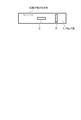
- FIG. 10 is a schematic diagram for illustrating the test pieces C and D used in the tensile test.
- the test piece C was a specimen whose longitudinal direction was parallel to the direction in which the fibers 6 extend
- the specimen D was a specimen whose longitudinal direction was perpendicular to the direction in which the fibers 6 extend.
- FIGS. 11A and 11B are photographs for illustrating the state of the tensile test.
- FIG. 11A is a photograph for illustrating the state at the start of the tensile test.
- FIG. 11B is a photograph for illustrating the state at the time of breaking the test piece.
- FIG. 12A is an optical micrograph of the test piece D.
- FIG. FIG. 12B is an optical micrograph of the test piece C.
- FIG. 13 is a graph for illustrating the result of the tensile test of the deposit 7.
- the test specimens C and D containing collagen had a thickness dimension of about 90 ⁇ m, a width dimension of 2 mm, and a length dimension of 12 mm.
- the extension speed was 1 mm / min.
- the tensile strength of the test piece C / the tensile strength of the test piece D was 5.6, and the tensile elongation was 9% to 11%.
- the tensile strength is the maximum stress / cross-sectional area.
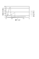
- FIG. 14 is a graph for comparing the result of the tensile test of the deposit 7 with the result of the tensile test of the fiber orientation sheets 70a and 70b.
- the test pieces C1 and D1 are test pieces formed from the deposit 7, and the test pieces C2 and D2 are test pieces formed from the fiber orientation sheets 70a and 70b (the deposit 7 subjected to the adhesion process described above). is there.
- the test pieces C1, C2, D1, and D2 containing collagen had a thickness of about 30 ⁇ m, a width of 2 mm, and a length of 12 mm.
- the extension speed was 1 mm / min.
- the fiber orientation sheets 70a and 70b When the tensile strength of the fiber orientation sheets 70a and 70b in one direction is F1, and the tensile strength of the fiber orientation sheets 70a and 70b in the direction orthogonal to this direction is F2, F1 is 28 MPa and F2 / F1 is 3. 2 However, F2> F1. Therefore, it was proved that the fiber orientation sheets 70a and 70b have high tensile strength and high tensile strength anisotropy. Moreover, it was proved that the fiber orientation sheets 70a and 70b are those in which the fibers 6 are oriented (the directions in which the fibers 6 extend are aligned).
- the surfaces of the fiber orientation sheets 70a and 70b were analyzed by the polarization FT-IR-ATR method to determine the direction in which the long axis of the molecule extends.
- the absorption intensity T1 when the wave number was 1640 cm ⁇ 1 was 0.075
- the absorption intensity T2 when the wave number was 1540 cm ⁇ 1 was 0.043.
- the absorbance ratio R1 (T1 / T2) in the predetermined polarization direction was 1.748
- the absorbance ratio R2 when the orientation of the fiber orientation sheets 70a and 70b was rotated by 90 ° was 1.575.
- the orientation degree parameter (R1 / R2) of the fiber orientation sheets 70a and 70b is 1.13.
- the orientation parameter (R1 / R2) was 1.04. Therefore, since the fiber orientation sheets 70a and 70b have a large orientation degree parameter (R1 / R2), it was proved that the directions in which the long axes of the molecules extend are aligned. Moreover, it was proved that the fiber orientation sheets 70a and 70b are those in which the fibers 6 are oriented (the directions in which the fibers 6 extend are aligned).
- Table 1 is a table for illustrating the effect of the “adhesion step”.
- the present invention can be applied not only to biocompatible materials such as collagen but also to industrial materials such as polyimide. That is, if the above-mentioned “adhesion step” is performed, it is possible to improve the degree of molecular orientation, improve the tensile strength, maintain the anisotropy of the tensile strength, and the like even with a fiber oriented sheet made of an industrial material.
Landscapes
- Engineering & Computer Science (AREA)
- Textile Engineering (AREA)
- Chemical & Material Sciences (AREA)
- Dispersion Chemistry (AREA)
- Mechanical Engineering (AREA)
- Nonwoven Fabrics (AREA)
- Materials For Medical Uses (AREA)
- Spinning Methods And Devices For Manufacturing Artificial Fibers (AREA)
- Artificial Filaments (AREA)
Abstract
実施形態に係る繊維配向シートは、含まれている繊維が密着状態にあり、第1の方向における引張強度をF1、前記第1の方向に直交する第2の方向における引張強度をF2とした場合に、以下の(1)~(3)を全て満足する。 (1)F2>F1である。 (2)F1が1MPa以上である。 (3)F2/F1が2以上である。
Description
本発明の実施形態は、繊維配向シート、及びその製造方法に関する。
エレクトロスピニング法(電界紡糸法、電荷誘導紡糸法などとも称される)を用いて微細な繊維を形成し、形成された繊維を堆積させることで作成された堆積体がある。
この場合、エレクトロスピニング法を用いて形成された繊維は引張強度が低いため、堆積体の引張強度も低くなる。
また、堆積体は、繊維をランダムに堆積して作成されるため引張強度の異方性を高くすることもできない。
そのため、引張強度が高く、且つ、引張強度の異方性が高いシートの開発が望まれていた。
この場合、エレクトロスピニング法を用いて形成された繊維は引張強度が低いため、堆積体の引張強度も低くなる。
また、堆積体は、繊維をランダムに堆積して作成されるため引張強度の異方性を高くすることもできない。
そのため、引張強度が高く、且つ、引張強度の異方性が高いシートの開発が望まれていた。
本発明が解決しようとする課題は、引張強度が高く、且つ、引張強度の異方性が高い繊維配向シート、及びその製造方法を提供することである。
実施形態に係る繊維配向シートは、含まれている繊維が密着状態にあり、第1の方向における引張強度をF1、前記第1の方向に直交する第2の方向における引張強度をF2とした場合に、以下の(1)~(3)を全て満足する。
(1)F2>F1である。
(2)F1が1MPa以上である。
(3)F2/F1が2以上である。
(1)F2>F1である。
(2)F1が1MPa以上である。
(3)F2/F1が2以上である。
以下、実施の形態について説明する。
(繊維配向シート)
本実施の形態に係る繊維配向シートは、繊維を含んでいる。
繊維は、例えば、エレクトロスピニング法を用いて形成することができる。
繊維は、高分子物質を含んでいる。高分子物質は、例えば、ポリプロピレン、ポリエチレン、ポリスチレン、ポリエチレンテレフタレート、ポリ塩化ビニル、ポリカーボネート、ナイロン、アラミド、ポリアクリレート、ポリメタクリレート、ポリイミド、ポリアミドイミド、ポリフッ化ビニリデン、ポリエーテルスルホンなどの工業材料、コラーゲン、ラミニン、ゼラチン、ポリアクリロニトリル、キチン、ポリグリコール酸、ポリ乳酸などの生体親和性材料などとすることができる。ただし、高分子物質は、例示をしたものに限定されるわけではない。
また、繊維同士は密着している。なお、後述する「密着工程」で用いる溶剤によっては、繊維の一部分が溶融し、溶融した部分において繊維同士が溶着している場合もあり得る。
そのため、本明細書においては、繊維同士が密着している状態、および、繊維同士が密着しさらに一部が溶着している状態を「密着状態」と称する。
そのため、本明細書においては、繊維同士が密着している状態、および、繊維同士が密着しさらに一部が溶着している状態を「密着状態」と称する。
繊維配向シートにおいては、含まれている繊維が密着状態にあるため、繊維の直径寸法を測定することが難しい(図6(b)を参照)。
ただし、後述する引張強度の異方性や、分子の長軸が延びる方向などから、密着状態にある繊維が存在することは証明できる。
また、後述する密着工程において、繊維がなるべく溶解しないようにされるため、繊維配向シートに含まれる繊維の直径寸法は、堆積体に含まれる繊維の直径寸法とすることができる。
ただし、後述する引張強度の異方性や、分子の長軸が延びる方向などから、密着状態にある繊維が存在することは証明できる。
また、後述する密着工程において、繊維がなるべく溶解しないようにされるため、繊維配向シートに含まれる繊維の直径寸法は、堆積体に含まれる繊維の直径寸法とすることができる。
この場合、堆積体に含まれる繊維の平均直径は、0.05μm以上、5μm以下とすることができる。
堆積体に含まれる繊維の平均直径は、例えば、後述する堆積体7の表面の電子顕微鏡写真を撮影し(図6(a)を参照)、電子顕微鏡写真により確認された任意の100本の繊維の直径寸法を平均することで求めることができる。
堆積体に含まれる繊維の平均直径は、例えば、後述する堆積体7の表面の電子顕微鏡写真を撮影し(図6(a)を参照)、電子顕微鏡写真により確認された任意の100本の繊維の直径寸法を平均することで求めることができる。
また、繊維配向シートにおいては、含まれている繊維が密着状態となっているので、繊維配向シートに含まれる空隙は小さなものとなる。繊維配向シートに含まれる空隙の最大寸法は、例えば、0.5μm未満である。空隙の最大寸法は、例えば、繊維配向シートの表面の電子顕微鏡写真を撮影し、電子顕微鏡写真により確認された空隙の寸法を測定することで求めることができる。
含まれている繊維士が密着状態となっていれば、繊維配向シートの引張強度を高くすることができる。
引張強度は、定速伸張形引張試験機などにより測定することができる。この場合、引張強度は、例えば、JIS P8113に準拠して測定することができる。
引張強度は、定速伸張形引張試験機などにより測定することができる。この場合、引張強度は、例えば、JIS P8113に準拠して測定することができる。
また、繊維配向シートにおいては、繊維の延びる方向がほぼ揃っている。すなわち、繊維配向シートにおいては、繊維が大体同じ方向に延びている。本明細書においては、繊維が大体同じ方向に延びていることを、繊維が「配向」されていると称する。
繊維が「配向」されていれば、繊維が延びる方向における繊維配向シートの引張強度は高くなる。一方、繊維の延びる方向と直交する方向における繊維配向シートの引張強度は低くなる。そのため、繊維配向シートの引張強度に異方性を持たせることができる。しかし、繊維の延びる方向と直交する方向における繊維配向シートの引張強度が低いことで、シートの機械的強度が不足し、装置内の搬送や培養実験、外科治療における作業が難しくなる場合がある。含まれている繊維が密着状態となっていれば、繊維が延びる方向と直交する方向における繊維配向シートの引張強度を高くすることができる。
繊維が「配向」されていれば、繊維が延びる方向における繊維配向シートの引張強度は高くなる。一方、繊維の延びる方向と直交する方向における繊維配向シートの引張強度は低くなる。そのため、繊維配向シートの引張強度に異方性を持たせることができる。しかし、繊維の延びる方向と直交する方向における繊維配向シートの引張強度が低いことで、シートの機械的強度が不足し、装置内の搬送や培養実験、外科治療における作業が難しくなる場合がある。含まれている繊維が密着状態となっていれば、繊維が延びる方向と直交する方向における繊維配向シートの引張強度を高くすることができる。
一方の方向(第1の方向の一例に相当する)における繊維配向シートの引張強度をF1とし、この方向に直交する方向(第2の方向の一例に相当する)における繊維配向シートの引張強度をF2とした場合、本実施の形態に係る繊維配向シートにおけるF1は1MPa以上であり、F2/F1は2以上である。ただし、F2>F1である。
ここで、繊維をランダムに堆積させて作成された堆積体は、引張強度が低く、且つ、堆積体の引張強度の異方性は低くなる(堆積体の引張強度の等方性は高くなる)。
この場合、前述したF2/F1は6~10程度となるが、F1が1MPa未満となり、裂け易い材料になる。
そのため、F2/F1を求めれば、繊維が配向されているか否かが分かる。
この場合、前述したF2/F1は6~10程度となるが、F1が1MPa未満となり、裂け易い材料になる。
そのため、F2/F1を求めれば、繊維が配向されているか否かが分かる。
また、特定の技術分野や用途などによっては、繊維の配向の度合いが高い(F2/F1が大きい)ことが重要となる場合もある。
本実施の形態に係る繊維配向シートは、繊維の配向の度合いが高いので、特定の技術分野や用途などにも適用することが可能となる。
例として、繊維の配向方向には高い引張強度や分子配向度を与えることができる。また、繊維の配向と直交する方向には、高い伸び特性を与えることができる。
本実施の形態に係る繊維配向シートは、繊維の配向の度合いが高いので、特定の技術分野や用途などにも適用することが可能となる。
例として、繊維の配向方向には高い引張強度や分子配向度を与えることができる。また、繊維の配向と直交する方向には、高い伸び特性を与えることができる。
また、延伸された高分子物質においては、分子の長軸が延びる方向(分子軸)が、高分子物質(繊維)が延びる方向となる傾向がある。そのため、繊維配向シートの表面における分子の長軸が延びる方向を調べれば、繊維が延びる方向、ひいては、繊維が配向されているか否かが分かる。
分子の長軸が延びる方向は、高分子物質の種類に応じた構造決定方法を用いて知ることができる。
例えば、ポリスチレンなどの場合にはラマン分光法を用いることができ、ポリイミドなどの場合には偏光吸光度分析法を用いることができる。
ここでは一例として、高分子物質がコラーゲンなどのアミド基を有する有機化合物である場合を説明する。アミド基を有する有機化合物の場合には、例えば、赤外分光法の一種である偏光FT-IR-ATR法を用いて分子の長軸が延びる方向、ひいては繊維が配向されているか否かを知ることができる。
分子の長軸が延びる方向は、高分子物質の種類に応じた構造決定方法を用いて知ることができる。
例えば、ポリスチレンなどの場合にはラマン分光法を用いることができ、ポリイミドなどの場合には偏光吸光度分析法を用いることができる。
ここでは一例として、高分子物質がコラーゲンなどのアミド基を有する有機化合物である場合を説明する。アミド基を有する有機化合物の場合には、例えば、赤外分光法の一種である偏光FT-IR-ATR法を用いて分子の長軸が延びる方向、ひいては繊維が配向されているか否かを知ることができる。
この場合、以下の様にして、繊維配向シートの表面を偏光FT-IR-ATR法により分析して、分子の長軸が延びる方向を求めることができる。
波数が1640cm-1の場合の吸収強度をT1、波数が1540cm-1の場合の吸収強度をT2とする。
この場合、吸収強度T1は、分子の長軸が延びる方向と直交する方向における吸収強度となる。吸収強度T2は、分子の長軸が延びる方向における吸収強度となる。
そのため、所定の偏光方向における吸光度比R1(T1/T2)が小さくなれば、その偏光方向に延びている分子が多いことが分かる。
波数が1640cm-1の場合の吸収強度をT1、波数が1540cm-1の場合の吸収強度をT2とする。
この場合、吸収強度T1は、分子の長軸が延びる方向と直交する方向における吸収強度となる。吸収強度T2は、分子の長軸が延びる方向における吸収強度となる。
そのため、所定の偏光方向における吸光度比R1(T1/T2)が小さくなれば、その偏光方向に延びている分子が多いことが分かる。
また、所定の偏光方向における吸光度比R1と、繊維配向シートの向きを変えた場合(例えば、繊維配向シートの向きを90°回転させた場合)の吸光度比R2を求め、R1/R2を配向度パラメータとすることができる。ただし、R1>R2である。
本実施の形態に係る繊維配向シートにおいては、R1/R2が大きくなる。例えば、後述するように、R1/R2は、1.1以上となる。
本実施の形態に係る繊維配向シートにおいては、R1/R2が大きくなる。例えば、後述するように、R1/R2は、1.1以上となる。
R1/R2が大きいということは、分子の長軸が延びる方向が揃っていることを意味している。
また、前述したように、延伸された高分子物質においては、分子の長軸が延びる方向が、繊維が延びる方向となる傾向がある。そのため、R1/R2が大きいということは、繊維が配向されている(繊維が延びる方向が揃っている)ことを意味している。
また、前述したように、延伸された高分子物質においては、分子の長軸が延びる方向が、繊維が延びる方向となる傾向がある。そのため、R1/R2が大きいということは、繊維が配向されている(繊維が延びる方向が揃っている)ことを意味している。
また、特定の技術分野や用途などによっては、繊維に含まれる高分子物質の分子の長軸が延びる方向が揃っている(R1/R2が大きい)ことが重要となる場合もある。
本実施の形態に係る繊維配向シートは、繊維に含まれる高分子物質の分子の長軸が延びる方向が揃っている(R1/R2が大きい)ので、特定の技術分野や用途などにも適用することが可能となる。
本実施の形態に係る繊維配向シートは、繊維に含まれる高分子物質の分子の長軸が延びる方向が揃っている(R1/R2が大きい)ので、特定の技術分野や用途などにも適用することが可能となる。
(繊維配向シートの製造方法)
次に、本実施の形態に係る繊維配向シートの製造方法について説明する。
まず、エレクトロスピニング装置1を用いて、微細な繊維を形成し、形成された繊維を堆積させて堆積体を形成する。また、形成された繊維を堆積させる際に、繊維を機械的に一方向に引っ張ることで、堆積体における繊維の延びる方向がなるべく揃うようにする。
次に、本実施の形態に係る繊維配向シートの製造方法について説明する。
まず、エレクトロスピニング装置1を用いて、微細な繊維を形成し、形成された繊維を堆積させて堆積体を形成する。また、形成された繊維を堆積させる際に、繊維を機械的に一方向に引っ張ることで、堆積体における繊維の延びる方向がなるべく揃うようにする。
図1は、エレクトロスピニング装置1を例示するための模式図である。
図1に示すように、エレクトロスピニング装置1には、ノズル2、電源3、および収集部4が設けられている。
ノズル2の内部には、原料液5を排出するための孔が設けられている。
電源3は、ノズル2に所定の極性の電圧を印加する。例えば、電源3は、ノズル2と収集部4との間の電位差が10kV以上となるように、ノズル2に電圧を印加する。ノズル2に印加する電圧の極性は、プラスとすることもできるし、マイナスとすることもできる。なお、図1に例示をした電源3は、ノズル2にプラスの電圧を印加する。
収集部4は、ノズル2の原料液5が排出される側に設けられている。収集部4は、接地されている。収集部4には、ノズル2に印加する電圧と逆極性の電圧を印加するようにしてもよい。また、収集部4は、円柱状を呈し、回転するようになっている。
原料液5は、高分子物質を溶媒に溶解したものである。
高分子物質には特に限定がなく、形成したい繊維6の材質に応じて適宜変更することができる。高分子物質は、例えば、ポリプロピレン、ポリエチレン、ポリスチレン、ポリエチレンテレフタレート、ポリ塩化ビニル、ポリカーボネート、ナイロン、アラミドなどの工業材料、コラーゲン、ラミニン、ゼラチン、ポリアクリロニトリル、キチン、ポリグリコール酸などの生体親和性材料などとすることができる。
溶媒は、高分子物質を溶解することができるものであればよい。溶媒は、溶解させる高分子物質に応じて適宜変更することができる。溶媒は、例えば、水、アルコール類(メタノール、エタノール、イソプロピルアルコール、トリフルオロエタノール、ヘキサフルオロ-2-プロパノールなど)、アセトン、ベンゼン、トルエン、シクロヘキサノン、N,N-ジメチルアセトアミド、N,N-ジメチルホルムアミド、N-メチル-2-ピロリドン、ジメチルスルホキシドなどとすることができる。
また、無機電解質、有機電解質、界面活性剤、消泡剤などの添加剤を使用してもよい。
なお、高分子物質および溶媒は、例示をしたものに限定されるわけではない。
原料液5は、表面張力によりノズル2の排出口の近傍に留まっている。
電源3は、ノズル2に電圧を印加する。すると、排出口の近傍にある原料液5が所定の極性に帯電する。図1に例示をしたものの場合には、排出口の近傍にある原料液5がプラスに帯電する。
収集部4は、接地されているので、ノズル2と収集部4の間に電界が形成される。そして、電気力線に沿って作用する静電力が表面張力より大きくなると、排出口の近傍にある原料液5が静電力により収集部4に向けて引き出される。引き出された原料液は、引き伸ばされ、原料液に含まれる溶媒が揮発することで繊維6が形成される。形成された繊維6が回転している収集部4の上に堆積することで、堆積体7が形成される。また、回転している収集部4の上に繊維6が堆積する際に、繊維6が回転方向に引っ張られる。
すなわち、形成された繊維6を堆積させる際に、繊維6を機械的に一方向に引っ張ることで、堆積体7における繊維の延びる方向が揃えられる。
なお、繊維6を機械的に一方向に引っ張る方法は例示をしたものに限定されるわけではない。例えば、繊維6が引き出される方向にガスを流し、ガス流により繊維6を機械的に一方向に引っ張ることもできる。
図2(a)は、静止した平板状の収集部に繊維6を堆積した場合の電子顕微鏡写真である。
図2(b)は、回転している収集部4の上に繊維6を堆積した場合の電子顕微鏡写真である。
図2(a)、(b)から分かるように、形成された繊維6を堆積させる際に、繊維6を機械的に一方向に引っ張れば、堆積体7における繊維6が延びる方向をある程度揃えることができる。また、繊維6同士の間の隙間(空隙)を少なくすることができる。
図2(b)は、回転している収集部4の上に繊維6を堆積した場合の電子顕微鏡写真である。
図2(a)、(b)から分かるように、形成された繊維6を堆積させる際に、繊維6を機械的に一方向に引っ張れば、堆積体7における繊維6が延びる方向をある程度揃えることができる。また、繊維6同士の間の隙間(空隙)を少なくすることができる。
ところが、回転する収集部4やガス流により繊維6を機械的に一方向に引っ張ると、風や電界の乱れが発生する。そのため、繊維6を機械的に一方向に引っ張るだけでは、繊維6が延びる方向を揃えることに限界がある。
そこで、本実施の形態に係る繊維配向シートの製造方法においては、以下の密着工程を行うことで、繊維6が延びる方向をさらに揃えるようにしている。
まず、堆積体7に揮発性の液体を供給する。
例えば、堆積体7を揮発性の液体に浸漬させる。
揮発性の液体には特に限定はないが、繊維6がなるべく溶解しないものとすることが好ましい。揮発性の液体は、例えば、アルコール類(メタノール、エタノール、イソプロピルアルコールなど)や、アルコール水溶液、アセトン、アセトニトリル、エチレングリコールなどとすることができる。
まず、堆積体7に揮発性の液体を供給する。
例えば、堆積体7を揮発性の液体に浸漬させる。
揮発性の液体には特に限定はないが、繊維6がなるべく溶解しないものとすることが好ましい。揮発性の液体は、例えば、アルコール類(メタノール、エタノール、イソプロピルアルコールなど)や、アルコール水溶液、アセトン、アセトニトリル、エチレングリコールなどとすることができる。
次に、以下の乾燥工程を行う。
図3(a)、(b)は、乾燥前の状態を例示するための模式斜視図である。
まず、図3(a)に示すように、揮発性の液体を含む堆積体7を基台100の上に載置する。
乾燥前においては、図3(b)に示すように、繊維6が延びる方向がある程度揃えられている。
図3(a)、(b)は、乾燥前の状態を例示するための模式斜視図である。
まず、図3(a)に示すように、揮発性の液体を含む堆積体7を基台100の上に載置する。
乾燥前においては、図3(b)に示すように、繊維6が延びる方向がある程度揃えられている。
続いて、揮発性の液体を含む堆積体7を乾燥させる。
図4(a)、(b)は、堆積体7と基台100との間に滑りが生じる状態で乾燥させた場合を例示するための模式斜視図である。
図5(a)、(b)は、堆積体7と基台100との間に滑りが生じ難い状態で乾燥させた場合を例示するための模式斜視図である。
なお、堆積体7と基台100との間の滑りは、繊維6の材料と、基台100の材料とで制御することができる。例えば、繊維6の材料がコラーゲンである場合には、基台100の材料をポリスチレンとすることで、堆積体7と基台100との間の滑りを抑制することができる。
図4(a)、(b)は、堆積体7と基台100との間に滑りが生じる状態で乾燥させた場合を例示するための模式斜視図である。
図5(a)、(b)は、堆積体7と基台100との間に滑りが生じ難い状態で乾燥させた場合を例示するための模式斜視図である。
なお、堆積体7と基台100との間の滑りは、繊維6の材料と、基台100の材料とで制御することができる。例えば、繊維6の材料がコラーゲンである場合には、基台100の材料をポリスチレンとすることで、堆積体7と基台100との間の滑りを抑制することができる。
乾燥手段には特に限定はない。例えば、揮発性の液体を含む堆積体7を大気中で乾燥させてもよいし(自然乾燥)、加熱して乾燥させてもよいし(加熱乾燥)、減圧環境下で乾燥させてもよい(減圧乾燥)。
堆積体7と基台100との間に滑りが生じる状態で乾燥させた場合には、図4(a)に示すように、堆積体7の体積が全体的に収縮して繊維配向シート70aが形成される。
堆積体7と基台100との間に滑りが生じ難い状態で乾燥させた場合には、図5(a)に示すように、堆積体7の厚み寸法が主に収縮して繊維配向シート70bが形成される。
堆積体7と基台100との間に滑りが生じ難い状態で乾燥させた場合には、図5(a)に示すように、堆積体7の厚み寸法が主に収縮して繊維配向シート70bが形成される。
ここで、繊維6と繊維6の間にある揮発性の液体には、毛管力が働いている。すなわち、繊維6と繊維6を密着させる方向に力が加わっている。そのため、乾燥が進むにつれ(揮発性の液体が除去されるにつれ)、繊維6と繊維6の間の距離が縮まり、図4(b)、図5(b)に示すように、繊維6と繊維6が密着状態となる。
以上の様にして、本実施の形態に係る繊維配向シート70a、70bを製造することができる。
以上の様にして、本実施の形態に係る繊維配向シート70a、70bを製造することができる。
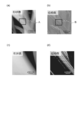
図6(a)は、堆積体7の電子顕微鏡写真である。すなわち、図6(a)は、揮発性の液体が供給される前の繊維6の状態を表している。
図6(b)は、繊維配向シート70a、70bの電子顕微鏡写真である。すなわち、図6(b)は、揮発性の液体が除去(乾燥)された後の繊維6の状態を表している。
図6(a)、(b)から分かるように、前述した密着工程を行えば、繊維6と繊維6が密着状態となる。この場合、図6(b)から分かるように、電子顕微鏡写真では繊維6が確認できないほど繊維6同士が密着した状態となる。
繊維6同士が密着状態となっていれば、繊維6が延びる方向をさらに揃えることができる。すなわち、繊維配向シート70a、70bにおいては、繊維6が配向されている。
なお、繊維配向シート70a、70bにおいて、繊維6同士が密着状態となっており、また、繊維6が配向されていることは、前述した引張強度の異方性や、分子の長軸が延びる方向などにより確認することができる。
またさらに、光学顕微鏡を用いれば繊維6に由来する配向の方向を確認することができる。
図7(a)、(b)は、繊維配向シート70a、70bの光学顕微鏡写真である。
図7(a)、(b)から分かるように、繊維配向シート70a、70bの表面を光学顕微鏡により観察すると、ピッチ寸法が100μm程度の縞構造を確認することができた。
この様な縞構造は、揮発性の液体が除去されて繊維6と繊維6が密着するにつれて、複数の繊維6の束が集合体となって一定間隔で収縮したため形成されたものと考えられる。
図7(a)、(b)は、繊維配向シート70a、70bの光学顕微鏡写真である。
図7(a)、(b)から分かるように、繊維配向シート70a、70bの表面を光学顕微鏡により観察すると、ピッチ寸法が100μm程度の縞構造を確認することができた。
この様な縞構造は、揮発性の液体が除去されて繊維6と繊維6が密着するにつれて、複数の繊維6の束が集合体となって一定間隔で収縮したため形成されたものと考えられる。
(実施例)
以下、実施例に基づいて繊維配向シートをさらに詳細に説明する。ただし、以下の実施例は、本発明を限定するものではない。
まず、以下のようにして堆積体7を形成した。
高分子物質は、生体親和性材料であるコラーゲンとした。
溶媒は、トリフルオロエタノールと、純水の混合溶媒とした。
原料液5は、2wt%~10wt%のコラーゲンと、80wt%~97wt%のトリフルオロエタノールと、1wt%~15wt%の純水との混合液とした。
エレクトロスピニング装置1は、図1に例示をした回転する収集部4を有するものとした。
エレクトロスピニング装置1により形成された繊維6は、コラーゲンを10wt%以上含むものとなった。
また、繊維6の直径は、70nm~180nm程度であった。
また、回転する収集部4により繊維6を機械的に一方向に引っ張ることで、堆積体7における繊維6が延びる方向をある程度揃えた。この場合、堆積体7における繊維6の状態は、前述した図2(b)に示したものとなった。
図8は、エレクトロスピニング装置1により形成された繊維6におけるコラーゲン分子の配向を例示するための模式図である。
図9(a)~(d)は、繊維6の表面の原子間力顕微鏡写真である。
図9(a)は、形状像である。図9(b)は、位相像である。図9(c)は、図9(a)中のA部の拡大写真である。図9(d)は、図9(b)中のB部の拡大写真である。
原子間力顕微鏡で位相像を取得すれば、繊維6の表面の弾性率変化を解析することができる。すなわち、位相像により、繊維6の表面における硬さ(弾性率)の差に由来にする筋状のコントラストを確認することができる。
図9(a)~(d)から分かるように、エレクトロスピニング装置1により形成された繊維6の表面を原子間力顕微鏡で分析すると、繊維6の軸方向に硬さの差に由来する筋状のコントラストを確認することができる。
この様な構成を有する繊維6を配向させれば、高い分子配向度を得ることができるものと考えられる。
次に、堆積体7をエタノールに浸漬させた。エタノールの濃度は、40wt%~ほぼ100wt%で行った。また、エタノールへの浸漬は大気中で行った。エタノールの温度は室温とした。浸漬時間は特に限定せず、エタノールが堆積体7中に十分に充填された時点で、堆積体7をエタノールから引き上げた。
次に、エタノールを含む堆積体7を乾燥させた。
乾燥は、大気中で行い、乾燥温度は室温とした。すなわち、エタノールを含む堆積体7を自然乾燥させた。
この場合、堆積体7と基台100との間に滑りが生じる状態で乾燥させることで繊維配向シート70aを作成した。また、堆積体7と基台100との間に滑りが生じ難い状態で乾燥させることで繊維配向シート70bを作成した。なお、堆積体7と基台100との間に滑りが生じ難い状態で乾燥させる場合には、ポリスチレンを用いて形成された基台100を用いた。
乾燥は、大気中で行い、乾燥温度は室温とした。すなわち、エタノールを含む堆積体7を自然乾燥させた。
この場合、堆積体7と基台100との間に滑りが生じる状態で乾燥させることで繊維配向シート70aを作成した。また、堆積体7と基台100との間に滑りが生じ難い状態で乾燥させることで繊維配向シート70bを作成した。なお、堆積体7と基台100との間に滑りが生じ難い状態で乾燥させる場合には、ポリスチレンを用いて形成された基台100を用いた。
以上の様にして、コラーゲンを含む繊維配向シート70a、70bを製造した。この場合、繊維配向シートにおける繊維6の状態は、前述した図6(b)、図7(a)、(b)に示したものとなった。
図6(b)、図7(a)、(b)から分かるように、繊維配向シート70a、70bに含まれる空隙は確認されなかった。
図6(b)、図7(a)、(b)から分かるように、繊維配向シート70a、70bに含まれる空隙は確認されなかった。
図10は、引張試験に用いる試験片C、Dを例示するための模式図である。
図10に示すように、試験片の長手方向が繊維6が延びる方向に平行なものを試験片C、試験片の長手方向が繊維6が延びる方向に垂直なものを試験片Dとした。
図11(a)、(b)は、引張試験の様子を例示するための写真である。
図11(a)は、引張試験開始時の様子を例示するための写真である。図11(b)は、試験片の破断時の様子を例示するための写真である。
図12(a)は、試験片Dの光学顕微鏡写真である。
図12(b)は、試験片Cの光学顕微鏡写真である。
図10に示すように、試験片の長手方向が繊維6が延びる方向に平行なものを試験片C、試験片の長手方向が繊維6が延びる方向に垂直なものを試験片Dとした。
図11(a)、(b)は、引張試験の様子を例示するための写真である。
図11(a)は、引張試験開始時の様子を例示するための写真である。図11(b)は、試験片の破断時の様子を例示するための写真である。
図12(a)は、試験片Dの光学顕微鏡写真である。
図12(b)は、試験片Cの光学顕微鏡写真である。
図13は、堆積体7の引張試験の結果を例示するためのグラフ図である。
なお、コラーゲンを含む試験片C、Dの厚み寸法は90μm程度、幅寸法は2mm、長さ寸法は12mmとした。また、伸張速度は、1mm/minとした。
図13から分かるように、試験片Cの引張強度/試験片Dの引張強度は5.6、引っ張り伸び率は、9%~11%であった。
なお、引張強度は、最大応力/断面積としている。
なお、コラーゲンを含む試験片C、Dの厚み寸法は90μm程度、幅寸法は2mm、長さ寸法は12mmとした。また、伸張速度は、1mm/minとした。
図13から分かるように、試験片Cの引張強度/試験片Dの引張強度は5.6、引っ張り伸び率は、9%~11%であった。
なお、引張強度は、最大応力/断面積としている。
図14は、堆積体7の引張試験の結果と、繊維配向シート70a、70bの引張試験の結果とを比較するためのグラフ図である。
なお、試験片C1、D1は堆積体7から形成された試験片、試験片C2、D2は繊維配向シート70a、70b(前述した密着工程が施された堆積体7)から形成された試験片である。
なお、コラーゲンを含む試験片C1、C2、D1、D2の厚み寸法は30μm程度、幅寸法は2mm、長さ寸法は12mmとした。また、伸張速度は、1mm/minとした。
ここで、繊維配向シート70a、70bの基台100側には、エタノール処理により繊維6がより緻密に密着した硬い面が形成される。
そのため、試験片D1において、この硬い面が、引張試験の初期に破断することで、図14に示すような引張応力のピークが生じたものと考えられる。
なお、試験片C1、D1は堆積体7から形成された試験片、試験片C2、D2は繊維配向シート70a、70b(前述した密着工程が施された堆積体7)から形成された試験片である。
なお、コラーゲンを含む試験片C1、C2、D1、D2の厚み寸法は30μm程度、幅寸法は2mm、長さ寸法は12mmとした。また、伸張速度は、1mm/minとした。
ここで、繊維配向シート70a、70bの基台100側には、エタノール処理により繊維6がより緻密に密着した硬い面が形成される。
そのため、試験片D1において、この硬い面が、引張試験の初期に破断することで、図14に示すような引張応力のピークが生じたものと考えられる。
一方の方向における繊維配向シート70a、70bの引張強度をF1とし、この方向に直交する方向における繊維配向シート70a、70bの引張強度をF2とした場合、F1は28MPaとなり、F2/F1は3.2となった。ただし、F2>F1である。
そのため、繊維配向シート70a、70bは、引張強度が高く、且つ、引張強度の異方性が高いものであることが証明された。また、繊維配向シート70a、70bは、繊維6が配向されている(繊維6が延びる方向が揃っている)ものであることが証明された。
そのため、繊維配向シート70a、70bは、引張強度が高く、且つ、引張強度の異方性が高いものであることが証明された。また、繊維配向シート70a、70bは、繊維6が配向されている(繊維6が延びる方向が揃っている)ものであることが証明された。
また、繊維配向シート70a、70bの表面を偏光FT-IR-ATR法により分析して、分子の長軸が延びる方向を求めた。
波数が1640cm-1の場合の吸収強度T1は0.075、波数が1540cm-1の場合の吸収強度T2は0.043となった。
所定の偏光方向における吸光度比R1(T1/T2)は1.748、繊維配向シート70a、70bの向きを90°回転させた場合の吸光度比R2は1.575となった。
波数が1640cm-1の場合の吸収強度T1は0.075、波数が1540cm-1の場合の吸収強度T2は0.043となった。
所定の偏光方向における吸光度比R1(T1/T2)は1.748、繊維配向シート70a、70bの向きを90°回転させた場合の吸光度比R2は1.575となった。
そのため、繊維配向シート70a、70bの配向度パラメータ(R1/R2)は、1.13となった。
なお、エタノールに浸漬させる前の堆積体7の表面を同様にして分析すると、配向度パラメータ(R1/R2)は、1.04となった。
そのため、繊維配向シート70a、70bは、配向度パラメータ(R1/R2)が大きいので、分子の長軸が延びる方向が揃っているものであることが証明された。また、繊維配向シート70a、70bは、繊維6が配向されている(繊維6が延びる方向が揃っている)ものであることが証明された。
なお、エタノールに浸漬させる前の堆積体7の表面を同様にして分析すると、配向度パラメータ(R1/R2)は、1.04となった。
そのため、繊維配向シート70a、70bは、配向度パラメータ(R1/R2)が大きいので、分子の長軸が延びる方向が揃っているものであることが証明された。また、繊維配向シート70a、70bは、繊維6が配向されている(繊維6が延びる方向が揃っている)ものであることが証明された。

表1から分かるように、本発明は、コラーゲンなどの生体親和性材料のみならず、ポリイミドなどの工業材料にも適用することができる。
すなわち、前述した「密着工程」を行えば、工業材料からなる繊維配向シートであっても分子配向度の向上、引張強度の向上、引張強度の異方性の維持などを図ることができる。
以上、本発明のいくつかの実施形態を例示したが、これらの実施形態は、例として提示したものであり、発明の範囲を限定することは意図していない。これら新規な実施形態は、その他の様々な形態で実施されることが可能であり、発明の要旨を逸脱しない範囲で、種々の省略、置き換え、変更などを行うことができる。これら実施形態やその変形例は、発明の範囲や要旨に含まれるとともに、請求の範囲に記載された発明とその均等の範囲に含まれる。また、前述の各実施形態は、相互に組み合わせて実施することができる。
Claims (6)
- 含まれている繊維が密着状態にあり、
第1の方向における引張強度をF1、前記第1の方向に直交する第2の方向における引張強度をF2とした場合に、以下の(1)~(3)を全て満足する繊維配向シート。
(1)F2>F1である。
(2)F1が1MPa以上である。
(3)F2/F1が2以上である。 - 前記繊維は、生体親和性材料を10wt%以上含む請求項1記載の繊維配向シート。
- 前記繊維は、アミド基を含み、
前記繊維配向シートの表面を偏光FT-IR-ATR法により分析した場合に、以下の式で表される配向度パラメータが1.1以上である請求項1または2に記載の繊維配向シート。
配向度パラメータは、R1/R2である。
R1は、所定の偏光方向における吸光度比である。
R2は、前記繊維配向シートの向きを90°回転させた場合の吸光度比である。
R1>R2である。
波数が1640cm-1の場合の吸収強度をT1、波数が1540cm-1の場合の吸収強度をT2とした場合に、吸光度比は、T1/T2である。 - エレクトロスピニング法を用いて繊維を形成し、前記繊維を堆積させて堆積体を形成する工程と、
前記堆積体に揮発性の液体を供給する工程と、
前記揮発性の液体を含む堆積体を乾燥させる工程と、
を備えた繊維配向シートの製造方法。 - 前記堆積体を形成する工程において、前記繊維を一方向に引っ張る請求項4記載の繊維配向シートの製造方法。
- 前記繊維は、生体親和性材料を2wt%以上含み、
前記揮発性の液体は、アルコールを含む請求項4または5に記載の繊維配向シートの製造方法。
Priority Applications (6)
| Application Number | Priority Date | Filing Date | Title |
|---|---|---|---|
| EP20170077.0A EP3702507B1 (en) | 2016-03-16 | 2016-08-31 | Method for manufacturing a fiber sheet |
| CN202010913463.2A CN111996680B (zh) | 2016-03-16 | 2016-08-31 | 纤维取向片 |
| CN201680002532.6A CN107407028B (zh) | 2016-03-16 | 2016-08-31 | 纤维取向片及其制造方法 |
| EP16890906.7A EP3460115B1 (en) | 2016-03-16 | 2016-08-31 | Sheet of oriented fibers and production process therefor |
| US15/460,820 US10801140B2 (en) | 2016-03-16 | 2017-03-16 | Fiber sheet and method for manufacturing same |
| US17/012,773 US11421360B2 (en) | 2016-03-16 | 2020-09-04 | Fiber sheet and method for manufacturing same |
Applications Claiming Priority (2)
| Application Number | Priority Date | Filing Date | Title |
|---|---|---|---|
| JP2016-053090 | 2016-03-16 | ||
| JP2016053090A JP6612664B2 (ja) | 2016-03-16 | 2016-03-16 | 繊維配向シート |
Related Child Applications (1)
| Application Number | Title | Priority Date | Filing Date |
|---|---|---|---|
| US15/460,820 Continuation US10801140B2 (en) | 2016-03-16 | 2017-03-16 | Fiber sheet and method for manufacturing same |
Publications (1)
| Publication Number | Publication Date |
|---|---|
| WO2017158868A1 true WO2017158868A1 (ja) | 2017-09-21 |
Family
ID=59851763
Family Applications (1)
| Application Number | Title | Priority Date | Filing Date |
|---|---|---|---|
| PCT/JP2016/075496 WO2017158868A1 (ja) | 2016-03-16 | 2016-08-31 | 繊維配向シート、及びその製造方法 |
Country Status (4)
| Country | Link |
|---|---|
| EP (2) | EP3460115B1 (ja) |
| JP (1) | JP6612664B2 (ja) |
| CN (2) | CN107407028B (ja) |
| WO (1) | WO2017158868A1 (ja) |
Cited By (1)
| Publication number | Priority date | Publication date | Assignee | Title |
|---|---|---|---|---|
| WO2020184136A1 (ja) * | 2019-03-12 | 2020-09-17 | 富士フイルム株式会社 | 不織布、不織布製造方法 |
Families Citing this family (2)
| Publication number | Priority date | Publication date | Assignee | Title |
|---|---|---|---|---|
| CN107938175B (zh) * | 2017-11-28 | 2020-05-15 | 北京理工大学 | 一种高取向柔性发光偏振复合纤维薄膜的制备方法及其用途 |
| JP2021183733A (ja) * | 2020-05-21 | 2021-12-02 | 株式会社東芝 | 繊維シートの製造方法及び繊維シートの製造装置 |
Citations (6)
| Publication number | Priority date | Publication date | Assignee | Title |
|---|---|---|---|---|
| JP2005126865A (ja) * | 2003-10-24 | 2005-05-19 | Asahi Kasei Fibers Corp | 高強度長繊維不織布 |
| JP2008303514A (ja) * | 2007-06-11 | 2008-12-18 | Japan Vilene Co Ltd | 静電紡糸不織布の製造方法 |
| JP2009233550A (ja) * | 2008-03-26 | 2009-10-15 | Kuraray Co Ltd | 気体フィルター用濾材 |
| JP2012527217A (ja) * | 2009-04-24 | 2012-11-08 | ジ・オハイオ・ステート・ユニバーシティ | 双方向微小環境系 |
| JP2013139655A (ja) | 2012-01-05 | 2013-07-18 | Teijin Ltd | 極細径繊維不織布およびその製造方法 |
| JP2014101320A (ja) * | 2012-11-21 | 2014-06-05 | Japan Vilene Co Ltd | 液体化粧料含有シート用基布 |
Family Cites Families (17)
| Publication number | Priority date | Publication date | Assignee | Title |
|---|---|---|---|---|
| US5234651A (en) * | 1991-09-12 | 1993-08-10 | Kigen Kawai | Dry-jet wet spinning of fibers including two steps of stretching before complete coagulation |
| JPH06200048A (ja) * | 1992-12-28 | 1994-07-19 | Sekisui Chem Co Ltd | 繊維強化熱可塑性樹脂シートの製造方法 |
| JP3427470B2 (ja) * | 1994-04-12 | 2003-07-14 | 東レ株式会社 | 液晶ポリエステル繊維 |
| JPH11222719A (ja) * | 1997-03-04 | 1999-08-17 | Kansai Shingijutsu Kenkyusho:Kk | 高配向ポリマー繊維及びその製造方法 |
| DE69803610T2 (de) * | 1997-03-04 | 2003-02-20 | Kansai Res Inst Kri Osaka | Hochorientierte Polymerfaser und Verfahren zu ihrer Herstellung |
| WO2001080921A2 (en) * | 2000-04-20 | 2001-11-01 | Emory University | Native protein mimetic fibers, fiber networks and fabrics for medical use |
| US7972981B2 (en) * | 2002-03-15 | 2011-07-05 | Fiberweb, Inc. | Microporous composite sheet material |
| JPWO2009072172A1 (ja) * | 2007-12-03 | 2011-04-21 | 株式会社グッドマン | ステント及びその製造方法 |
| CN101525812A (zh) * | 2008-12-31 | 2009-09-09 | 温州市瓯海昌隆化纤制品厂 | 一种高强度低热收缩聚乳酸非织造布及其制造方法 |
| KR101424850B1 (ko) * | 2010-05-25 | 2014-08-01 | 코오롱패션머티리얼 (주) | 폴리이미드 다공성 나노섬유 웹 및 그 제조방법 |
| JP5739154B2 (ja) * | 2010-12-24 | 2015-06-24 | 阿波製紙株式会社 | 膜の支持体 |
| CN102087921B (zh) * | 2011-01-21 | 2014-01-01 | 清华大学 | 一种自支撑超级电容器电极材料及其制备方法 |
| CN102499800B (zh) * | 2011-11-17 | 2014-07-16 | 苏州大学 | 血管支架及其制备方法 |
| CN103285431B (zh) * | 2013-06-21 | 2015-07-22 | 苏州大学 | 一种抗凝血丝素材料及其制备方法 |
| CN103996813A (zh) * | 2014-05-28 | 2014-08-20 | 天津工业大学 | 一种双向增强型静电纺锂离子电池隔膜的制备方法及装置 |
| CN104749683A (zh) * | 2015-03-31 | 2015-07-01 | 华南理工大学 | 一种光学偏振片及其制备方法 |
| KR101802641B1 (ko) * | 2016-03-29 | 2017-11-28 | 경북대학교 산학협력단 | 친수성이 향상된 폴리우레탄 나노섬유 및 그의 제조방법 |
-
2016
- 2016-03-16 JP JP2016053090A patent/JP6612664B2/ja active Active
- 2016-08-31 CN CN201680002532.6A patent/CN107407028B/zh active Active
- 2016-08-31 EP EP16890906.7A patent/EP3460115B1/en active Active
- 2016-08-31 EP EP20170077.0A patent/EP3702507B1/en active Active
- 2016-08-31 CN CN202010913463.2A patent/CN111996680B/zh active Active
- 2016-08-31 WO PCT/JP2016/075496 patent/WO2017158868A1/ja active Application Filing
Patent Citations (6)
| Publication number | Priority date | Publication date | Assignee | Title |
|---|---|---|---|---|
| JP2005126865A (ja) * | 2003-10-24 | 2005-05-19 | Asahi Kasei Fibers Corp | 高強度長繊維不織布 |
| JP2008303514A (ja) * | 2007-06-11 | 2008-12-18 | Japan Vilene Co Ltd | 静電紡糸不織布の製造方法 |
| JP2009233550A (ja) * | 2008-03-26 | 2009-10-15 | Kuraray Co Ltd | 気体フィルター用濾材 |
| JP2012527217A (ja) * | 2009-04-24 | 2012-11-08 | ジ・オハイオ・ステート・ユニバーシティ | 双方向微小環境系 |
| JP2013139655A (ja) | 2012-01-05 | 2013-07-18 | Teijin Ltd | 極細径繊維不織布およびその製造方法 |
| JP2014101320A (ja) * | 2012-11-21 | 2014-06-05 | Japan Vilene Co Ltd | 液体化粧料含有シート用基布 |
Non-Patent Citations (1)
| Title |
|---|
| See also references of EP3460115A4 |
Cited By (3)
| Publication number | Priority date | Publication date | Assignee | Title |
|---|---|---|---|---|
| WO2020184136A1 (ja) * | 2019-03-12 | 2020-09-17 | 富士フイルム株式会社 | 不織布、不織布製造方法 |
| JPWO2020184136A1 (ja) * | 2019-03-12 | 2021-12-16 | 富士フイルム株式会社 | 不織布、不織布製造方法 |
| JP7167302B2 (ja) | 2019-03-12 | 2022-11-08 | 富士フイルム株式会社 | 不織布製造方法 |
Also Published As
| Publication number | Publication date |
|---|---|
| CN111996680B (zh) | 2022-09-20 |
| EP3702507B1 (en) | 2022-04-27 |
| CN107407028A (zh) | 2017-11-28 |
| JP6612664B2 (ja) | 2019-11-27 |
| JP2017166092A (ja) | 2017-09-21 |
| EP3460115A1 (en) | 2019-03-27 |
| EP3460115A4 (en) | 2020-07-29 |
| CN107407028B (zh) | 2020-10-02 |
| EP3460115B1 (en) | 2022-09-07 |
| CN111996680A (zh) | 2020-11-27 |
| EP3702507A1 (en) | 2020-09-02 |
Similar Documents
| Publication | Publication Date | Title |
|---|---|---|
| Rashid et al. | Mechanical properties of electrospun fibers—a critical review | |
| JP6612664B2 (ja) | 繊維配向シート | |
| Niu et al. | Upward needleless electrospinning of nanofibers | |
| US11421360B2 (en) | Fiber sheet and method for manufacturing same | |
| Wong et al. | Surface morphology and mechanical response of randomly oriented electrospun nanofibrous membrane | |
| Kim et al. | A study on the microstructural changes and mechanical behaviors of carbon fibers induced by optimized electrochemical etching | |
| Schneider et al. | Polyethylene oxide nanofiber production by electrospinning | |
| Stachewicz et al. | Surface free energy analysis of electrospun fibers based on Rayleigh-Plateau/Weber instabilities | |
| JP6749432B2 (ja) | 繊維配向材の製造方法 | |
| JP2019163588A (ja) | 繊維配向シートの製造方法、及び繊維配向シート | |
| Pise et al. | Study of process parameters affecting the diameter and morphology of electrospun polyvinylidene fluoride (PVDF) nanofibers | |
| JP6470327B2 (ja) | 繊維配向材、及びその製造方法 | |
| Lee et al. | Rayleigh-instability-driven morphology transformation of electrospun polymer fibers imaged by in situ optical microscopy and stimulated Raman scattering microscopy | |
| JP6929424B2 (ja) | 繊維配向材の製造方法 | |
| Long et al. | The influence of electrospinning distances on fibre diameter of poly (vinyl alcohol) electrospun nanofibres | |
| Liu et al. | Mechanical properties of piezoelectric PVDF/MWCNT fibers prepared by flat/hollow cylindrical near-field electrospinning process | |
| Shi et al. | Optimization and characterization of poly (phthalazinone ether ketone)(PPEK) heat-resistant porous fiberous mat by electrospinning | |
| US20180222145A1 (en) | Fiber-oriented material and method for manufacturing the same | |
| Demirtas | Fabrication, Characterization and Modeling of Aligned Polyacrylonitrile-Based Electrospun Carbon Nanofibers | |
| Cai et al. | Nanomechanical tests on continuous near-field electrospun PAN nanofibers reveal abnormal mechanical and morphology size effects | |
| Li et al. | Particle-like beads and daughter jet cascades in electrospinning | |
| Lagoudas et al. | Electrospinning of continuous piezoelectric yarns for composite application | |
| Lupu et al. | THE IMPORTANCE OF NOVEL TECHNOLOGIES IN THE UNIVERSITY CURRICULA | |
| Deng et al. | Mechanical Properties of Magnetic-Field-Assisted Electrospun Poly (vinylidene fluoride)(PVDF) Nanofibers | |
| BR102020023995A2 (pt) | Coletor vazado de hastes rotativo para coleta e secagem rápida de micro/nanofibras produzidas pelo método de fiação por sopro em solução (sbs) |
Legal Events
| Date | Code | Title | Description |
|---|---|---|---|
| REEP | Request for entry into the european phase |
Ref document number: 2016890906 Country of ref document: EP |
|
| NENP | Non-entry into the national phase |
Ref country code: DE |
|
| 121 | Ep: the epo has been informed by wipo that ep was designated in this application |
Ref document number: 16890906 Country of ref document: EP Kind code of ref document: A1 |